EP4461247A1 - Electrical connector for a catheter device - Google Patents
Electrical connector for a catheter device Download PDFInfo
- Publication number
- EP4461247A1 EP4461247A1 EP24174515.7A EP24174515A EP4461247A1 EP 4461247 A1 EP4461247 A1 EP 4461247A1 EP 24174515 A EP24174515 A EP 24174515A EP 4461247 A1 EP4461247 A1 EP 4461247A1
- Authority
- EP
- European Patent Office
- Prior art keywords
- electrical
- distal
- proximal
- end effector
- pads
- Prior art date
- Legal status (The legal status is an assumption and is not a legal conclusion. Google has not performed a legal analysis and makes no representation as to the accuracy of the status listed.)
- Pending
Links
Images



Classifications
-
- A—HUMAN NECESSITIES
- A61—MEDICAL OR VETERINARY SCIENCE; HYGIENE
- A61B—DIAGNOSIS; SURGERY; IDENTIFICATION
- A61B18/00—Surgical instruments, devices or methods for transferring non-mechanical forms of energy to or from the body
- A61B18/04—Surgical instruments, devices or methods for transferring non-mechanical forms of energy to or from the body by heating
- A61B18/12—Surgical instruments, devices or methods for transferring non-mechanical forms of energy to or from the body by heating by passing a current through the tissue to be heated, e.g. high-frequency current
- A61B18/14—Probes or electrodes therefor
- A61B18/1492—Probes or electrodes therefor having a flexible, catheter-like structure, e.g. for heart ablation
-
- A—HUMAN NECESSITIES
- A61—MEDICAL OR VETERINARY SCIENCE; HYGIENE
- A61B—DIAGNOSIS; SURGERY; IDENTIFICATION
- A61B18/00—Surgical instruments, devices or methods for transferring non-mechanical forms of energy to or from the body
-
- A—HUMAN NECESSITIES
- A61—MEDICAL OR VETERINARY SCIENCE; HYGIENE
- A61B—DIAGNOSIS; SURGERY; IDENTIFICATION
- A61B18/00—Surgical instruments, devices or methods for transferring non-mechanical forms of energy to or from the body
- A61B18/02—Surgical instruments, devices or methods for transferring non-mechanical forms of energy to or from the body by cooling, e.g. cryogenic techniques
-
- A—HUMAN NECESSITIES
- A61—MEDICAL OR VETERINARY SCIENCE; HYGIENE
- A61B—DIAGNOSIS; SURGERY; IDENTIFICATION
- A61B18/00—Surgical instruments, devices or methods for transferring non-mechanical forms of energy to or from the body
- A61B18/04—Surgical instruments, devices or methods for transferring non-mechanical forms of energy to or from the body by heating
- A61B18/12—Surgical instruments, devices or methods for transferring non-mechanical forms of energy to or from the body by heating by passing a current through the tissue to be heated, e.g. high-frequency current
- A61B18/1206—Generators therefor
-
- A—HUMAN NECESSITIES
- A61—MEDICAL OR VETERINARY SCIENCE; HYGIENE
- A61M—DEVICES FOR INTRODUCING MEDIA INTO, OR ONTO, THE BODY; DEVICES FOR TRANSDUCING BODY MEDIA OR FOR TAKING MEDIA FROM THE BODY; DEVICES FOR PRODUCING OR ENDING SLEEP OR STUPOR
- A61M25/00—Catheters; Hollow probes
- A61M25/0097—Catheters; Hollow probes characterised by the hub
-
- A—HUMAN NECESSITIES
- A61—MEDICAL OR VETERINARY SCIENCE; HYGIENE
- A61B—DIAGNOSIS; SURGERY; IDENTIFICATION
- A61B18/00—Surgical instruments, devices or methods for transferring non-mechanical forms of energy to or from the body
- A61B2018/00053—Mechanical features of the instrument of device
- A61B2018/00172—Connectors and adapters therefor
- A61B2018/00178—Electrical connectors
-
- A—HUMAN NECESSITIES
- A61—MEDICAL OR VETERINARY SCIENCE; HYGIENE
- A61B—DIAGNOSIS; SURGERY; IDENTIFICATION
- A61B18/00—Surgical instruments, devices or methods for transferring non-mechanical forms of energy to or from the body
- A61B2018/00315—Surgical instruments, devices or methods for transferring non-mechanical forms of energy to or from the body for treatment of particular body parts
- A61B2018/00345—Vascular system
- A61B2018/00351—Heart
-
- A—HUMAN NECESSITIES
- A61—MEDICAL OR VETERINARY SCIENCE; HYGIENE
- A61B—DIAGNOSIS; SURGERY; IDENTIFICATION
- A61B18/00—Surgical instruments, devices or methods for transferring non-mechanical forms of energy to or from the body
- A61B2018/00315—Surgical instruments, devices or methods for transferring non-mechanical forms of energy to or from the body for treatment of particular body parts
- A61B2018/00345—Vascular system
- A61B2018/00351—Heart
- A61B2018/00357—Endocardium
-
- A—HUMAN NECESSITIES
- A61—MEDICAL OR VETERINARY SCIENCE; HYGIENE
- A61B—DIAGNOSIS; SURGERY; IDENTIFICATION
- A61B18/00—Surgical instruments, devices or methods for transferring non-mechanical forms of energy to or from the body
- A61B2018/00571—Surgical instruments, devices or methods for transferring non-mechanical forms of energy to or from the body for achieving a particular surgical effect
- A61B2018/00577—Ablation
-
- A—HUMAN NECESSITIES
- A61—MEDICAL OR VETERINARY SCIENCE; HYGIENE
- A61B—DIAGNOSIS; SURGERY; IDENTIFICATION
- A61B18/00—Surgical instruments, devices or methods for transferring non-mechanical forms of energy to or from the body
- A61B2018/00571—Surgical instruments, devices or methods for transferring non-mechanical forms of energy to or from the body for achieving a particular surgical effect
- A61B2018/00577—Ablation
- A61B2018/00583—Coblation, i.e. ablation using a cold plasma
-
- A—HUMAN NECESSITIES
- A61—MEDICAL OR VETERINARY SCIENCE; HYGIENE
- A61B—DIAGNOSIS; SURGERY; IDENTIFICATION
- A61B18/00—Surgical instruments, devices or methods for transferring non-mechanical forms of energy to or from the body
- A61B2018/00571—Surgical instruments, devices or methods for transferring non-mechanical forms of energy to or from the body for achieving a particular surgical effect
- A61B2018/00613—Irreversible electroporation
-
- A—HUMAN NECESSITIES
- A61—MEDICAL OR VETERINARY SCIENCE; HYGIENE
- A61B—DIAGNOSIS; SURGERY; IDENTIFICATION
- A61B18/00—Surgical instruments, devices or methods for transferring non-mechanical forms of energy to or from the body
- A61B2018/00636—Sensing and controlling the application of energy
- A61B2018/00773—Sensed parameters
- A61B2018/00791—Temperature
-
- A—HUMAN NECESSITIES
- A61—MEDICAL OR VETERINARY SCIENCE; HYGIENE
- A61B—DIAGNOSIS; SURGERY; IDENTIFICATION
- A61B18/00—Surgical instruments, devices or methods for transferring non-mechanical forms of energy to or from the body
- A61B2018/00636—Sensing and controlling the application of energy
- A61B2018/00773—Sensed parameters
- A61B2018/00839—Bioelectrical parameters, e.g. ECG, EEG
-
- A—HUMAN NECESSITIES
- A61—MEDICAL OR VETERINARY SCIENCE; HYGIENE
- A61B—DIAGNOSIS; SURGERY; IDENTIFICATION
- A61B18/00—Surgical instruments, devices or methods for transferring non-mechanical forms of energy to or from the body
- A61B2018/00636—Sensing and controlling the application of energy
- A61B2018/00773—Sensed parameters
- A61B2018/00875—Resistance or impedance
-
- A—HUMAN NECESSITIES
- A61—MEDICAL OR VETERINARY SCIENCE; HYGIENE
- A61B—DIAGNOSIS; SURGERY; IDENTIFICATION
- A61B18/00—Surgical instruments, devices or methods for transferring non-mechanical forms of energy to or from the body
- A61B18/02—Surgical instruments, devices or methods for transferring non-mechanical forms of energy to or from the body by cooling, e.g. cryogenic techniques
- A61B2018/0212—Surgical instruments, devices or methods for transferring non-mechanical forms of energy to or from the body by cooling, e.g. cryogenic techniques using an instrument inserted into a body lumen, e.g. catheter
-
- A—HUMAN NECESSITIES
- A61—MEDICAL OR VETERINARY SCIENCE; HYGIENE
- A61B—DIAGNOSIS; SURGERY; IDENTIFICATION
- A61B18/00—Surgical instruments, devices or methods for transferring non-mechanical forms of energy to or from the body
- A61B18/04—Surgical instruments, devices or methods for transferring non-mechanical forms of energy to or from the body by heating
- A61B18/12—Surgical instruments, devices or methods for transferring non-mechanical forms of energy to or from the body by heating by passing a current through the tissue to be heated, e.g. high-frequency current
- A61B18/14—Probes or electrodes therefor
- A61B2018/1405—Electrodes having a specific shape
-
- A—HUMAN NECESSITIES
- A61—MEDICAL OR VETERINARY SCIENCE; HYGIENE
- A61B—DIAGNOSIS; SURGERY; IDENTIFICATION
- A61B18/00—Surgical instruments, devices or methods for transferring non-mechanical forms of energy to or from the body
- A61B18/04—Surgical instruments, devices or methods for transferring non-mechanical forms of energy to or from the body by heating
- A61B18/12—Surgical instruments, devices or methods for transferring non-mechanical forms of energy to or from the body by heating by passing a current through the tissue to be heated, e.g. high-frequency current
- A61B18/14—Probes or electrodes therefor
- A61B2018/1405—Electrodes having a specific shape
- A61B2018/1407—Loop
-
- A—HUMAN NECESSITIES
- A61—MEDICAL OR VETERINARY SCIENCE; HYGIENE
- A61B—DIAGNOSIS; SURGERY; IDENTIFICATION
- A61B18/00—Surgical instruments, devices or methods for transferring non-mechanical forms of energy to or from the body
- A61B18/04—Surgical instruments, devices or methods for transferring non-mechanical forms of energy to or from the body by heating
- A61B18/12—Surgical instruments, devices or methods for transferring non-mechanical forms of energy to or from the body by heating by passing a current through the tissue to be heated, e.g. high-frequency current
- A61B18/14—Probes or electrodes therefor
- A61B2018/1405—Electrodes having a specific shape
- A61B2018/1435—Spiral
-
- A—HUMAN NECESSITIES
- A61—MEDICAL OR VETERINARY SCIENCE; HYGIENE
- A61B—DIAGNOSIS; SURGERY; IDENTIFICATION
- A61B2218/00—Details of surgical instruments, devices or methods for transferring non-mechanical forms of energy to or from the body
- A61B2218/001—Details of surgical instruments, devices or methods for transferring non-mechanical forms of energy to or from the body having means for irrigation and/or aspiration of substances to and/or from the surgical site
- A61B2218/002—Irrigation
Definitions
- the present invention relates generally to medical devices comprising an end effector with electrodes, and further relates to, but not exclusively, to electrical connectors for such medical devices.
- Cardiac arrhythmias such as atrial fibrillation (AF) occur when regions of cardiac tissue abnormally conduct electric signals to adjacent tissue. This disrupts the normal cardiac cycle and causes asynchronous rhythm. Certain procedures exist for treating arrhythmia, including surgically disrupting the origin of the signals causing the arrhythmia and disrupting the conducting pathway for such signals. By selectively ablating cardiac tissue by application of energy via a catheter, it is sometimes possible to cease or modify the propagation of unwanted electrical signals from one portion of the heart to another.
- AF atrial fibrillation
- Regions of cardiac tissue can be mapped by a medical probe to identify the abnormal electrical signals.
- the same or different medical probe can be used to perform ablation.
- Some example probes include a number of spines with electrodes positioned thereon. The electrodes are generally attached to the spines and the spines are configured to extend outwardly when deployed from a sheath. The electrodes are then brought into contact with tissue for mapping or ablation of the tissue.
- catheters include end effectors having spines arranged in a planar array while other end effectors are designed with spines configured to bow radially outward when deployed from the sheath.
- each different end effector design can have a different number of electrodes with the number of electrodes ranging from one electrode to hundreds of electrodes. As will be appreciated, as the number of electrodes increases for a given end effector, so does the number of electrical wires or traces that must be connected to each end effector.
- an electrical connector for a catheter device can comprise a body extending along a longitudinal axis from a proximal portion to a distal portion.
- the proximal portion can be configured to be attached to a tubular shaft and the distal portion can be configured to be attached to an end effector.
- the electrical connector can comprise a plurality of proximal electrical pads disposed on the body at the proximal portion.
- the proximal electrical pads can be configured to be in electrical communication with a plurality of tubular shaft electrical pads.
- the electrical connector can comprise a plurality of distal electrical pads disposed on the body at the distal portion.
- the distal electrical pads can be configured to be in electrical communication with a plurality of end effector electrical pads.
- the electrical connector can comprise a plurality of electrical traces. Each electrical trace can connect a respective proximal electrical pad to a respective distal electrical pad.
- the disclosed technology can include a medical probe comprising a tubular shaft extending along a longitudinal axis of the medical probe, an end effector comprising a plurality of electrodes, and an electrical connector disposed between the tubular shaft and the end effector.
- the electrical connector can comprise a body extending along the longitudinal axis from a proximal portion to a distal portion, a plurality of proximal electrical pads disposed on the body at the proximal portion, a plurality of distal electrical pads disposed on the body at the distal portion, and a plurality of electrical traces.
- the proximal electrical pads can be configured to align with, and electrically connect to, a plurality of tubular shaft electrical pads disposed on the tubular shaft.
- the distal electrical pads can be configured to align with, and electrically connect to, a plurality of end effector electrical pads disposed on the end effector. Each electrical trace can connect a respective proximal electrical pad to a respective distal electrical pad.
- the disclosed technology relates to an electrical connector that can be used with multiple different end effectors and catheter shafts.
- the electrical connector includes electrical connection points on the proximal side and the distal side that can be configured to align with corresponding electrical connection points on the catheter shaft and the end effector.
- the electrical connector can make it possible for multiple different end effectors to be used with the same catheter shaft.
- a given catheter shaft can be configured to be used with a plurality of end effectors, with each end effector having a different number of electrodes, different configuration of spines, and or a different end use (e.g., mapping or ablation).
- the electrical connector can be positioned between a chosen end effector and the catheter shaft and be configured to align and electrically connect the end effector with the catheter shaft. In this way, the electrical connector can greatly simplify the manufacturing process by eliminating the requirement that each catheter shaft be made specifically for each end effector.
- the terms “about” or “approximately” for any numerical values or ranges indicate a suitable dimensional tolerance that allows the part or collection of components to function for its intended purpose as described herein. More specifically, “about” or “approximately” may refer to the range of values ⁇ 20% of the recited value, e.g. "about 90%” may refer to the range of values from 71% to 110%.
- the terms "patient,” “host,” “user,” and “subject” refer to any human or animal subject and are not intended to limit the systems or methods to human use, although use of the subject invention in a human patient represents a preferred embodiment.
- proximal indicates a location closer to the operator or physician whereas “distal” indicates a location further away to the operator or physician.
- vasculature of a "patient,” “host,” “user,” and “subject” can be vasculature of a human or any animal.
- an animal can be a variety of any applicable type, including, but not limited thereto, mammal, veterinarian animal, livestock animal or pet type animal, etc.
- the animal can be a laboratory animal specifically selected to have certain characteristics similar to a human (e.g., rat, dog, pig, monkey, or the like).
- the subject can be any applicable human patient, for example.
- physician can include a doctor, surgeon, technician, scientist, operator, or any other individual or delivery instrumentation associated with delivery of a multi-electrode catheter for the treatment of drug refractory atrial fibrillation to a subject.
- IRE irreversible electroporation
- PEF pulsed electric field
- PFA pulsed field ablation
- Ablating or ablation as it relates to the devices and corresponding systems of this disclosure is used throughout this disclosure in reference to non-thermal ablation of cardiac tissue for certain conditions including, but not limited to, arrhythmias, atrial flutter ablation, pulmonary vein isolation, supraventricular tachycardia ablation, and ventricular tachycardia ablation.
- the term “ablate” or “ablation” also includes known methods, devices, and systems to achieve various forms of bodily tissue ablation as understood by a person skilled in
- bipolar and unipolar when used to refer to ablation schemes describe ablation schemes which differ with respect to electrical current path and electric field distribution.
- Bipolar refers to an ablation scheme utilizing a current path between two electrodes that are both positioned at a treatment site; current density and electric flux density is typically approximately equal at each of the two electrodes.
- Unipolar refers to ablation scheme utilizing a current path between two electrodes where one electrode having a high current density and high electric flux density is positioned at a treatment site, and a second electrode having comparatively lower current density and lower electric flux density is positioned remotely from the treatment site.
- biphasic pulse and “monophasic pulse” refer to respective electrical signals.
- Biphasic pulse refers to an electrical signal having a positive-voltage phase pulse (referred to herein as “positive phase”) and a negative-voltage phase pulse (referred to herein as “negative phase”).
- Monophasic pulse refers to an electrical signal having only a positive or only a negative phase.
- a system providing the biphasic pulse is configured to prevent application of a direct current voltage (DC) to a patient.
- DC direct current voltage
- the average voltage of the biphasic pulse can be zero volts with respect to ground or other common reference voltage.
- the system can include a capacitor or other protective component.
- each phase of the biphasic and/or monophasic pulse preferably has a square shape having an essentially constant voltage amplitude during a majority of the phase duration.
- Phases of the biphasic pulse are separated in time by an interphase delay.
- the interphase delay duration is preferably less than or approximately equal to the duration of a phase of the biphasic pulse.
- the interphase delay duration is more preferably about 25% of the duration of the phase of the biphasic pulse.
- tubular and tube are to be construed broadly and are not limited to a structure that is a right cylinder or strictly circumferential in cross-section or of a uniform cross-section throughout its length.
- the tubular structures are generally illustrated as a substantially right cylindrical structure.
- the tubular structures may have a tapered or curved outer surface without departing from the scope of the present disclosure.
- the present disclosure is related to systems, method or uses and devices that can be used for IRE ablation of cardiac tissue to treat cardiac arrhythmias.
- Ablative energies are typically provided to cardiac tissue by a tip portion of a catheter which can deliver ablative energy alongside the tissue to be ablated.
- Some example catheters include three-dimensional structures at the tip portion and are configured to administer ablative energy from various electrodes positioned on the three-dimensional structures. Ablative procedures incorporating such example catheters can be visualized using fluoroscopy.
- a thermal technique such as radio frequency (RF) energy and cryoablation
- RF radio frequency
- cryoablation to correct a malfunctioning heart
- cardiac electropotentials need to be measured at various locations of the myocardium.
- temperature measurements during ablation provide data enabling the efficacy of the ablation.
- the electropotentials and the temperatures are measured before, during, and after the actual ablation.
- RF approaches can have risks that can lead to tissue charring, burning, steam pop, phrenic nerve palsy, pulmonary vein stenosis, and esophageal fistula.
- Cryoablation is an alternative approach to RF ablation that can reduce some thermal risks associated with RF ablation.
- maneuvering cryoablation devices and selectively applying cryoablation is generally more challenging compared to RF ablation; therefore, cryoablation is not viable in certain anatomical geometries which may be reached by electrical ablation devices.
- the present disclosure can include electrodes configured for RF ablation, cryoablation, and/or irreversible electroporation (IRE).
- IRE can be referred to throughout this disclosure interchangeably as pulsed electric field (PEF) ablation and pulsed field ablation (PFA).
- PEF pulsed electric field
- PFA pulsed field ablation
- IRE as discussed in this disclosure is a non-thermal cell death technology that can be used for ablation of atrial arrhythmias.
- biphasic voltage pulses are applied to disrupt cellular structures of myocardium.
- the biphasic pulses are non-sinusoidal and can be tuned to target cells based on electrophysiology of the cells.
- IRE In contrast, to ablate using RF, a sinusoidal voltage waveform is applied to produce heat at the treatment area, indiscriminately heating all cells in the treatment area. IRE therefore has the capability to spare adjacent heat sensitive structures or tissues which would be of benefit in the reduction of possible complications known with ablation or isolation modalities. Additionally, or alternatively, monophasic pulses can be utilized.
- Electroporation can be induced by applying a pulsed electric field across biological cells to cause reversable (temporary) or irreversible (permanent) creation of pores in the cell membrane.
- the cells have a transmembrane electrostatic potential that is increased above a resting potential upon application of the pulsed electric field. While the transmembrane electrostatic potential remains below a threshold potential, the electroporation is reversable, meaning the pores can close when the applied pulse electric field is removed, and the cells can self-repair and survive. If the transmembrane electrostatic potential increases beyond the threshold potential, the electroporation is irreversible, and the cells become permanently permeable.
- the cells die due to a loss of homeostasis and typically die by apoptosis.
- cells of differing types have differing threshold potential. For instance, heart cells have a threshold potential of approximately 500 V/cm, whereas for bone it is 3000 V/cm. These differences in threshold potential allow IRE to selectively target tissue based on threshold potential.
- the solution of this disclosure includes systems and methods for applying electrical signals from catheter electrodes positioned in the vicinity of myocardial tissue to generate an ablative energy to ablate the myocardial tissue.
- the systems and methods can be effective to ablate targeted tissue by inducing irreversible electroporation.
- the systems and methods can be effective to induce reversible electroporation as part of a diagnostic procedure. Reversible electroporation occurs when the electricity applied with the electrodes is below the electric field threshold of the target tissue allowing cells to repair. Reversible electroporation does not kill the cells but allows a physician to see the effect of reversible electroporation on electrical activation signals in the vicinity of the target location.
- Example systems and methods for reversible electroporation is disclosed in U.S. Patent Publication 2021/0162210 , the entirety of which is incorporated herein by reference.
- the pulsed electric field, and its effectiveness to induce reversible and/or irreversible electroporation, can be affected by physical parameters of the system and biphasic pulse parameters of the electrical signal.
- Physical parameters can include electrode contact area, electrode spacing, electrode geometry, etc. Examples presented herein generally include physical parameters adapted to effectively induce reversible and/or irreversible electroporation.
- Biphasic pulse parameters of the electrical signal can include voltage amplitude, pulse duration, pulse interphase delay, inter-pulse delay, total application time, delivered energy, etc.
- parameters of the electrical signal can be adjusted to induce both reversible and irreversible electroporation given the same physical parameters. Examples of various systems and methods of ablation including IRE are presented in U.S.
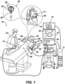
- System 10 includes multiple catheters, which are percutaneously inserted by physician 24 through the patient's 23 vascular system into a chamber or vascular structure of a heart 12.
- a delivery sheath catheter is inserted into the left or right atrium near a desired location in heart 12.
- a plurality of catheters can be inserted into the delivery sheath catheter so as to arrive at the desired location.
- the plurality of catheters may include catheters dedicated for sensing Intracardiac Electrogram (IEGM) signals, catheters dedicated for ablating and/or catheters dedicated for both sensing and ablating.
- An example catheter 14 that is configured for sensing and ablating is illustrated herein.
- Physician 24 brings a distal tip 28 (sometimes referred to herein as end effector 28) of catheter 14 into contact with the heart wall for sensing a target site in heart 12. For ablation, physician 24 would similarly bring a distal end of an ablation catheter to a target site for ablating.
- Catheter 14 is an exemplary catheter that includes one and preferably multiple electrodes 26 optionally distributed over a plurality of spines 22 at distal tip 28 and configured to sense the IEGM signals and/or to ablate tissue.
- Catheter 14 may additionally include a position sensor 29 embedded in or near distal tip 28 for tracking position and orientation of distal tip 28.
- position sensor 29 is a magnetic based position sensor including three magnetic coils for sensing three-dimensional (3D) position and orientation.
- Magnetic based position sensor 29 may be operated together with a location pad 25 including a plurality of magnetic coils 32 configured to generate magnetic fields in a predefined working volume. Real time position of distal tip 28 of catheter 14 may be tracked based on magnetic fields generated with location pad 25 and sensed by magnetic based position sensor 29. Details of the magnetic based position sensing technology are described in U.S. Patent Nos. 5,391,199 ; 5,443,489 ; 5,558,091 ; 6,172,499 ; 6,239,724 ; 6,332,089 ; 6,484,118 ; 6,618,612 ; 6,690,963 ; 6,788,967 ; 6,892,091 , the entireties of each of which are incorporated herein by reference.
- System 10 includes one or more electrode patches 38 positioned for skin contact on patient 23 to establish location reference for location pad 25 as well as impedance-based tracking of electrodes 26.
- impedance-based tracking electrical current is directed toward electrodes 26 and sensed at electrode skin patches 38 so that the location of each electrode can be triangulated via the electrode patches 38. Details of the impedance-based location tracking technology are described in US Patent Nos. 7,536,218 ; 7,756,576 ; 7,848,787 ; 7,869,865 ; and 8,456,182 , the entireties of each of which are incorporated herein by reference.
- a recorder 11 displays electrograms 21 captured with body surface ECG electrodes 18 and intracardiac electrograms (IEGM) captured with electrodes 26 of catheter 14.
- Recorder 11 may include pacing capability for pacing the heart rhythm and/or may be electrically connected to a standalone pacer.
- System 10 may include an ablation energy generator 50 that is adapted to conduct ablative energy to one or more of electrodes at a distal tip of a catheter configured for ablating.
- Energy produced by ablation energy generator 50 may include, but is not limited to, radiofrequency (RF) energy or pulsed-field ablation (PFA) energy, including monopolar or bipolar high-voltage DC pulses as may be used to effect irreversible electroporation (IRE), or combinations thereof.
- RF radiofrequency
- PFA pulsed-field ablation
- IRE irreversible electroporation
- Patient interface unit (PIU) 30 is an interface configured to establish electrical communication between catheters, electrophysiological equipment, power supply and a workstation 55 for controlling operation of system 10.
- Electrophysiological equipment of system 10 may include for example, multiple catheters, location pad 25, body surface ECG electrodes 18, electrode patches 38, ablation energy generator 50, and recorder 11.
- PIU 30 additionally includes processing capability for implementing real-time computations of location of the catheters and for performing ECG calculations.
- Workstation 55 includes memory, processor unit with memory or storage with appropriate operating software loaded therein, and user interface capability. Workstation 55 may provide multiple functions, optionally including (1) modeling the endocardial anatomy in three-dimensions (3D) and rendering the model or anatomical map 20 for display on a display device 27, (2) displaying on display device 27 activation sequences (or other data) compiled from recorded electrograms 21 in representative visual indicia or imagery superimposed on the rendered anatomical map 20, (3) displaying real-time location and orientation of multiple catheters within the heart chamber, and (4) displaying on display device 27 sites of interest such as places where ablation energy has been applied.
- One commercial product embodying elements of the system 10 is available as the CARTO TM 3 System, available from Biosense Webster, Inc., 31 Technology Drive, Suite 200, Irvine, CA 92618, USA.
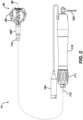
- FIG. 2 is a schematic pictorial illustration of an end effector 28, electrical connector assembly 200, and handle 110, in accordance with the disclosed technology.
- the catheter 14 can include a handle 110, a tubular shaft 112, an electrical connector 200, and an end effector 28.
- the end effector 28 can be inserted into a heart 12 of a patient by being inserted through a delivery sheath.
- the catheter 14 can be configured such that the end effector 28 can be steered by manipulation of the handle 110 and/or by an actuator 111 disposed on the handle 110.
- the handle 110 can further include an irrigation supply line 120 and an electrical connection point 130.
- the irrigation supply line 120 can be connected to an irrigation supply and be configured to deliver irrigation fluid to the end effector 28.
- the electrical connection point 130 can be or include an electrical plug or other components that allow the catheter 14 to be connected to the PIU 30 to receive and/or to transmit electrical signals to the electrodes 26 on the end effector 28.
- the end effector 28 shown in FIG. 2 illustrates a basket catheter having a plurality of spines 22 bowing radially outward from a longitudinal axis 86.
- a plurality of electrodes 26 can be attached to the spines 22 with the electrodes 26 being configured for detecting electrophysiological signals and/or for delivering ablative energy to tissues.
- the end effector 28 shown in FIG. 2 is offered for illustrative purposes and, as will become apparent throughout this disclosure, various other types of end effectors 28 can be used in place of the basket catheter shown in FIG. 2 .
- An electrical connector 200 can be disposed between the tubular shaft 112 and the end effector 28.
- the electrical connector 200 can be configured to electrically connect the electrodes 26 to the tubular shaft 112 and the electrical connection point 130 and, ultimately, with the PIU 30 to receive and/or transmit electrical signals to or from the electrodes 26.
- the electrical connector 200 can be configured to be used with multiple different types of end effectors 28 and tubular shafts 112.
- the tubular shaft 112 can be a universal tubular shaft 112 having multiple wires or electrical traces extending therethrough and having electrical pads disposed at the distal end for connecting to the electrical connector 200.
- the tubular shaft 112 can be configured such that it can be used with multiple different types of end effectors 28 and the electrical connector 200 can act as an adapter between the tubular shaft 112 and the multiple different types of end effector 28.
- FIG. 3 is an exploded view showing the electrical connector 200 with a distal end of the tubular shaft 112 and a proximal end of the end effector 28, in accordance with the disclosed technology. For the sake of simplicity, only a portion of the tubular shaft 112 and the end effector 28 are shown. As shown, the electrical connector 200 can be disposed between the distal end of the tubular shaft 112 and the proximal end of the end effector 28. The end effector 28 can have an end effector electrical connection assembly 210 configured to physically and electrically connect to the electrical connector 200. Similarly, as shown in FIG.
- the distal end of the tubular shaft 112 can have a tubular shaft connection assembly 230 configured to physically and electrically connect to the electrical connector 200.
- FIG. 3 further illustrates electrical traces 240 that extend through the tubular shaft 112 and can include termination points 242 that can be configured to electrically connect with the handle 110.
- the electrical connector 200 is shown as being generally cylindrical throughout the figures, it will be appreciated that the electrical connector 200 can comprises various other shapes other than that shown.
- the electrical connector 200 can be a rectangular prism, a pentagonal prism, a hexagonal prism, comprise a star cross-sectional shape, etc.
- the electrical connector 200 can be configured to taper from one end to the other end (e.g., taper from the proximal end to the distal end, and vice-versa), taper at both ends, etc. Accordingly, the disclosed technology should not be construed as being limited to the cylinder shape as shown in the figures.
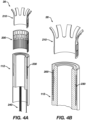
- FIG. 4A is an exploded section view of the tubular shaft 112, electrical connector 200, and the end effector 28 while FIG. 4B is a partially-assembled view of the same components, in accordance with the disclosed technology.
- the electrical connector 200 can be configured to fit in the proximal end of the tubular shaft 112 and be in electrical communication with the tubular shaft connection assembly 230.
- the end effector electrical connection assembly 210 can be configured to fit in the proximal end of the tubular shaft 112 and be in electrical communication with the electrical connector 200.
- the electrical connector 200 can facilitate electrical connection between the tubular shaft connection assembly 230 and the end effector electrical connection assembly 210.
- FIG. 5A is a perspective view of a proximal portion of an end effector 28, in accordance with the disclosed technology. For the sake of simplicity, only a portion of the end effector 28 is shown. As will be appreciated by one of skill in the art, the end effector 28 shown in FIG. 5A can represent a proximal portion of a basket assembly with a plurality of spines 22 and a plurality of electrodes. As shown in FIG. 5A , the end effector 28 can include proximal hub 212 having a plurality of first end effector electrical pads 214 and a plurality of second end effector electrical pads 216.
- the first end effector electrical pads 214 and the second end effector electrical pads 216 can each be electrically connected to respective electrodes 26 disposed on the spines 22. Alternatively, or in addition, at least some of the first end effector electrical pads 214 or the second end effector electrical pads 216 can be in electrical communication with other sensors or devices disposed on the end effector 28 such as position sensors, temperature sensors, etc. In some examples, the first end effector electrical pads 214 can be electrically connected to a plurality of mapping electrodes while the second end effector electrical pads 216 can be electrically connected with a plurality of ablation electrodes, or vice-versa.
- first end effector electrical pads 214 and the second end effector electrical pads 216 can be arranged and configured according to the particular application of the end effector 28.
- end effector 28 is shown as being a basket catheter, it will be appreciated that other types of end effectors can take the place of the basket catheter shown.
- FIG. 5B is a top view of a proximal portion of the end effector 28 of FIG. 5A , in accordance with the disclosed technology.
- the proximal hub 212 can have a lumen 218 extending therethrough.
- the end effector 28 can have an irrigation hub, push rod, or various other components of the end effector 28 extending through the lumen 218.
- FIG. 6A is a perspective view of an electrical connector 200, in accordance with the disclosed technology.
- the electrical connector 200 can include a body 222 having a plurality of proximal electrical pads 228 disposed at a proximal end of the body 222 and configured to contact, and be in electrical communication with, the tubular shaft electrical pads 236 (as shown in FIGs. 7A and 7B ) when assembled.
- the electrical connector 200 can further include a plurality of first distal electrical pads 224 and a plurality of second distal electrical pads 226 disposed at a distal end of the body 222 and configured to contact and be in electrical communication with the first and second end effector electrical pads 214, 216.
- the proximal electrical pads 228 can each be electrically connected to the first distal electrical pads 224 or the second distal electrical pads 226 via a plurality of electrical traces 229 (or wires).
- the plurality of first distal electrical pads 224, the plurality of second distal electrical pads 226, and the plurality of proximal electrical pads 228 can be disposed radially as well as longitudinally around the electrical connector 200.
- the proximal electrical pads 228, the first distal electrical pads 224, and the second distal electrical pads 226 can each be disposed on an inwardly-facing surface or an outwardly-facing surface of the body 222. Alternatively, only some of the proximal electrical pads 228, the first distal electrical pads 224, or the second distal electrical pads 226 can be disposed on the inwardly-facing surface of the body 222 while the remainder can be disposed on the outwardly-facing surface of the body 222.
- the proximal electrical pads 228, the first distal electrical pads 224, and the second distal electrical pads 226 can be positioned on either surface to correspond with the arrangement of the configuration of the end effector electrical connection assembly 210 and the tubular shaft connection assembly 230.
- the end effector electrical connection assembly 210 comprises first and second end effector electrical pads 214, 216 on an inwardly-facing surface of the end effector electrical connection assembly 210
- the corresponding the first and second distal electrical pads 224, 226 can be disposed on the outwardly-facing surface of the body 222, and vice-versa.
- FIG. 6B is a first side view while FIG. 6C is a second side view of the electrical connector 200, in accordance with the disclosed technology.
- the body 222 can include an alignment member 223 that can be configured to align with, and be compliant with, a corresponding alignment member disposed on the end effector 28 and/or the tubular shaft 112 (not shown).
- the alignment member 223 can be a notch, as shown, or the alignment member 223 can be a protrusion or other similar member that can cause the end effector 28 and/or the tubular shaft 112 to be aligned with the electrical connector 200 in only one orientation.
- the electrical connector 200 can be configured to ensure the end effector 28 and tubular shaft 112 are aligned (or “clocked") correctly with the electrical connector 200 and that the electrical pads are all properly aligned.
- the electrical connector 200 can further include colors, markings, or other features that ensure the electrical connector 200 is properly aligned with the end effector 28 and tubular shaft 112 when assembled.
- FIG. 6C further shows a gap 225 that can be formed in the electrical connector 200.
- the gap 225 for example, can be a result of the electrical connector 200 initially being formed as planar sheet and then formed into the cylindrical form shown. Furthermore, the gap 225 can permit the body 222 to flex and enable easier assembly with the end effector 28 and tubular shaft 112.
- proximal electrical pads 228, first distal electrical pads 224, and the second distal electrical pads 226 of the electrical connector 200 shown in FIGs. 6A-6C are offered for illustrative purposes and various other arrangements are contemplated and are included within the scope of this disclosure. Therefore, the scope of this disclosure should not be limited to the particular arrangement of components shown and described herein.
- the electrical connector 200 can be configured such, when selected distal electrical pads 224, 226 are in electrical communication with corresponding first and second end effector electrical pads 214, 216, the corresponding proximal electrical pads 228 can similarly be in electrical communication with tubular shaft electrical pads 236 that correspond to the first and second end effector electrical pads 214, 216. That is, if an end effector 28 does not have as many electrical pads as there are electrical pads on the electrical connector, the electrical can be configured such that the electrical pads that are actually used align with, and/or electrically connected to, the corresponding tubular shaft electrical pads.
- tubular shaft electrical pads 236 are in electrical communication with corresponding end effector electrical pads (214, 216) via the electrical connector 200, and corresponding proximal electrical pads 228 that are not in electrical communication with tubular shaft electrical pads 236 are aligned with distal electrical pads (224, 226) that are not in electrical communication with end effector electrical pads (214, 216).
- FIG. 7A is a perspective view while FIG. 7B is a top view of the distal end of the tubular shaft 112, in accordance with the disclosed technology.
- the tubular shaft 112 can comprise a shaft body 232 comprising a recess 234 formed into the distal end of the shaft body 232 that can be configured to receive the electrical connector 200 and at least part of the end effector 28.
- the recess can be sized such that the tubular shaft 112 forms a friction fit with the electrical connector 200 and/or the end effector 28.
- the tubular shaft 112 can further include a lumen 238 extending therethrough.
- the lumen 238 can be sized to receive a push rod, an irrigation tube, or various other components of the end effector 28 extending through the lumen 238.
- the distal end of the tubular shaft 112 can further include a plurality of tubular shaft electrical pads 236 that can be disposed radially around the tubular shaft 112.
- the tubular shaft electrical pads 236 can be arranged such that the tubular shaft electrical pads 236 are configured to contact and be in electrical communication with the proximal electrical pads 228.
- FIG. 8 is a perspective exploded view of another example medical probe 800 including a tubular shaft 112, electrical connector 200, and the end effector 28, in accordance with the disclosed technology.
- the medical probe 800 can comprise all of the same features as the catheter 14 previously described except that the medical probe 800 can include a plurality of wires connectors 840 instead of the recess 234 and tubular shaft electrical pads 236 previously described.
- the wire connectors 840 can include a wire 842 and a wire electrical pad 844 disposed at a distal end of the wire 842.
- the proximal end of the wire 842 can be connected to the electrical connection point 130 on the handle 110.
- the wire electrical pads 844 as further shown in FIGs. 9A and 9B , can be configured to be connected to the proximal electrical pads 228 of the electrical connector 200.
- the wire electrical pads 844 can be secured within the tubular shaft 112 by a harness or other apparatus configured to keep the wire electrical pads 844 in place such that the proximal electrical pads 228 can be aligned and in contact with the wire electrical pads 844 when the electrical connector 200 is inserted into (or around) the tubular shaft 112.
- the electrical connector 200 can be configured to be attached to a plurality of different types of end effectors.
- FIGs. 10A-10D illustrate various different types of end effectors that can be attached to the electrical connector 200.
- the electrical connector can be attached to a planar array catheter 1000A ( FIG. 10A ), a spiral or circular catheter 1000B ( FIG. 10B ), a basket catheter 1000C ( FIG. 10C ), or catheters having spines extending outwardly such as the spine catheter 1000D shown in FIG. 10D .
- the various end effectors shown and described in FIGs. 10A-10D can include varying numbers, types, and arrangements of electrodes attached thereto.
- FIGs. 10A-10D are not intended to be limiting and are offered solely for illustrative purposes as the electrical connector 200 can be configured to electrically connect various other types of end effectors to the tubular shaft 112.
- the electrical connector 200 can make it possible for each of these catheters, as well as various other catheters not shown, to be attached to the tubular shaft 112 in an easy and efficient manner.
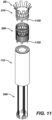
- FIG. 11 is an exploded view of another example of the tubular shaft 112, the electrical connector 200, and the end effector 28, in accordance with the disclosed technology.
- the example shown in FIG. 11 illustrates the end effector 28 and the electrical connector 200 comprising a mechanical connector 1102 that can be configured to attach the end effector 28 to the electrical connector 200 and/or the tubular shaft 112 and to attach the electrical connector 200 to the tubular shaft 112.
- the mechanical connectors 1102 are shown as being on a proximal side of the electrical connector 200 and the end effector 28, however, it should be appreciated by one of skill in the art that the mechanical connectors 1102 can be disposed on the distal side of the tubular shaft 112 and/or the electrical connector 200 instead of, or in addition to, being on the proximal side of the electrical connector 200 and the end effector 28.
- the mechanical connectors 1102 can be configured to interlock with corresponding mechanical connectors (not shown) on the tubular shaft 112, the electrical connector 200, and/or the end effector 28.
- the mechanical connectors 1102 can be or include a bayonet mount, a snap fitting, a threaded connector, or other similar mechanical connectors that can attach the components together.
- the mechanical connectors 1102 can be in place of, or in addition to, the alignment members previously described.
- the number of mechanical connectors 1102 can be varied depending on the particular application. For example, a single mechanical connector 1102 can be included or multiple mechanical connectors 1102 can be included.
- an adhesive can be used to connect the tubular shaft 112, electrical connector 200, and end effector 28 to each other.
Landscapes
- Health & Medical Sciences (AREA)
- Life Sciences & Earth Sciences (AREA)
- Surgery (AREA)
- Engineering & Computer Science (AREA)
- Animal Behavior & Ethology (AREA)
- General Health & Medical Sciences (AREA)
- Biomedical Technology (AREA)
- Heart & Thoracic Surgery (AREA)
- Veterinary Medicine (AREA)
- Public Health (AREA)
- Nuclear Medicine, Radiotherapy & Molecular Imaging (AREA)
- Molecular Biology (AREA)
- Otolaryngology (AREA)
- Medical Informatics (AREA)
- Physics & Mathematics (AREA)
- Plasma & Fusion (AREA)
- Cardiology (AREA)
- Biophysics (AREA)
- Pulmonology (AREA)
- Anesthesiology (AREA)
- Hematology (AREA)
- Surgical Instruments (AREA)
Abstract
The disclosed technology includes an electrical connector for a catheter device comprising a body extending along a longitudinal axis from a proximal portion to a distal portion, the proximal portion configured to be attached to a tubular shaft and the distal portion configured to be attached to an end effector. The electrical connector can comprise a plurality of proximal electrical pads disposed on the body at the proximal portion, the proximal electrical pads configured to be in electrical communication with a plurality of tubular shaft electrical pads. The electrical connector can comprise a plurality of distal electrical pads disposed on the body at the distal portion, the distal electrical pads configured to be in electrical communication with a plurality of end effector electrical pads. The electrical connector can comprise a plurality of electrical traces. Each electrical trace can connect a respective proximal electrical pad to a respective distal electrical pad.
Description
- The present invention relates generally to medical devices comprising an end effector with electrodes, and further relates to, but not exclusively, to electrical connectors for such medical devices.
- Cardiac arrhythmias, such as atrial fibrillation (AF), occur when regions of cardiac tissue abnormally conduct electric signals to adjacent tissue. This disrupts the normal cardiac cycle and causes asynchronous rhythm. Certain procedures exist for treating arrhythmia, including surgically disrupting the origin of the signals causing the arrhythmia and disrupting the conducting pathway for such signals. By selectively ablating cardiac tissue by application of energy via a catheter, it is sometimes possible to cease or modify the propagation of unwanted electrical signals from one portion of the heart to another.
- Regions of cardiac tissue can be mapped by a medical probe to identify the abnormal electrical signals. The same or different medical probe can be used to perform ablation. Some example probes include a number of spines with electrodes positioned thereon. The electrodes are generally attached to the spines and the spines are configured to extend outwardly when deployed from a sheath. The electrodes are then brought into contact with tissue for mapping or ablation of the tissue.
- Various different catheter designs exist to achieve mapping or ablation of cardiac tissues in many different places in the heart. For example, some catheters include end effectors having spines arranged in a planar array while other end effectors are designed with spines configured to bow radially outward when deployed from the sheath. Further, each different end effector design can have a different number of electrodes with the number of electrodes ranging from one electrode to hundreds of electrodes. As will be appreciated, as the number of electrodes increases for a given end effector, so does the number of electrical wires or traces that must be connected to each end effector. Traditionally, catheters are made with individual wires running to each end effector with those individual wires extending through the catheter shaft all the way to the handle, making manufacturing of the catheters difficult and time consuming. What is needed, therefore, is a device and method for reducing the complexity, time, and associate cost of manufacturing a medical probes having different numbers of electrodes disposed on the end effector. These and other problems can be addressed by the technology disclosed herein.
- There is provided, in accordance with the disclosed technology, an electrical connector for a catheter device. The electrical connector can comprise a body extending along a longitudinal axis from a proximal portion to a distal portion. The proximal portion can be configured to be attached to a tubular shaft and the distal portion can be configured to be attached to an end effector. The electrical connector can comprise a plurality of proximal electrical pads disposed on the body at the proximal portion. The proximal electrical pads can be configured to be in electrical communication with a plurality of tubular shaft electrical pads. The electrical connector can comprise a plurality of distal electrical pads disposed on the body at the distal portion. The distal electrical pads can be configured to be in electrical communication with a plurality of end effector electrical pads. The electrical connector can comprise a plurality of electrical traces. Each electrical trace can connect a respective proximal electrical pad to a respective distal electrical pad.
- The disclosed technology can include a medical probe comprising a tubular shaft extending along a longitudinal axis of the medical probe, an end effector comprising a plurality of electrodes, and an electrical connector disposed between the tubular shaft and the end effector.
- The electrical connector can comprise a body extending along the longitudinal axis from a proximal portion to a distal portion, a plurality of proximal electrical pads disposed on the body at the proximal portion, a plurality of distal electrical pads disposed on the body at the distal portion, and a plurality of electrical traces. The proximal electrical pads can be configured to align with, and electrically connect to, a plurality of tubular shaft electrical pads disposed on the tubular shaft. The distal electrical pads can be configured to align with, and electrically connect to, a plurality of end effector electrical pads disposed on the end effector. Each electrical trace can connect a respective proximal electrical pad to a respective distal electrical pad.
- The present disclosure will be more fully understood from the following detailed description of embodiments thereof, taken together with the drawings, in which:
-
FIG. 1 is a schematic pictorial illustration of a medical system including a medical probe with a distal end comprising electrodes, in accordance with the disclosed technology; -
FIG. 2 is a schematic pictorial illustration of an end effector, electrical connector assembly, and handle, in accordance with the disclosed technology; -
FIG. 3 is an exploded view of the tubular shaft, electrical connector, and the end effector, in accordance with the disclosed technology; -
FIG. 4A is an exploded section view of the tubular shaft, electrical connector, and the end effector, in accordance with the disclosed technology; -
FIG. 4B is a section view of a partially assembled view of the tubular shaft, electrical connector, and the end effector, in accordance with the disclosed technology; -
FIG. 5A is a perspective view of a proximal portion of an end effector, in accordance with the disclosed technology; -
FIG. 5B is a top view of a proximal portion of an end effector, in accordance with the disclosed technology; -
FIG. 6A is a perspective view of an electrical connector, in accordance with the disclosed technology; -
FIG. 6B is a first side view of the electrical connector, in accordance with the disclosed technology; -
FIG. 6C is a second side view of the electrical connector, in accordance with the disclosed technology; -
FIG. 7A is a perspective view of a distal end of a catheter shaft, in accordance with the disclosed technology; -
FIG. 7B is a top view of the distal end of the catheter shaft, in accordance with the disclosed technology; -
FIG. 8 is a perspective exploded view of another example tubular shaft, electrical connector, and the end effector, in accordance with the disclosed technology; -
FIG. 9A is a perspective view of an electrical wire and connection pad, in accordance with the disclosed technology; -
FIG. 9B is a perspective view of the electrical wire connected to the electrical connector, in accordance with the disclosed technology; -
FIG. 10A is an example planar end effector, in accordance with the disclosed technology; -
FIG. 10B is an example of a circular end effector, in accordance with the disclosed technology; -
FIG. 10C is an example basket catheter end effector, in accordance with the disclosed technology; -
FIG. 10D is an example end effector having a plurality of arms, in accordance with the disclosed technology; and -
FIG. 11 is an exploded view of another example of the electrical connector assembly, in accordance with the disclosed technology. - The disclosed technology relates to an electrical connector that can be used with multiple different end effectors and catheter shafts. The electrical connector includes electrical connection points on the proximal side and the distal side that can be configured to align with corresponding electrical connection points on the catheter shaft and the end effector. In this way, the electrical connector can make it possible for multiple different end effectors to be used with the same catheter shaft. For example, a given catheter shaft can be configured to be used with a plurality of end effectors, with each end effector having a different number of electrodes, different configuration of spines, and or a different end use (e.g., mapping or ablation). The electrical connector can be positioned between a chosen end effector and the catheter shaft and be configured to align and electrically connect the end effector with the catheter shaft. In this way, the electrical connector can greatly simplify the manufacturing process by eliminating the requirement that each catheter shaft be made specifically for each end effector.
- The following detailed description should be read with reference to the drawings, in which like elements in different drawings are identically numbered. The drawings, which are not necessarily to scale, depict selected embodiments and are not intended to limit the scope of the invention. The detailed description illustrates by way of example, not by way of limitation, the principles of the invention. This description will clearly enable one skilled in the art to make and use the invention, and describes several embodiments, adaptations, variations, alternatives and uses of the invention, including what is presently believed to be the best mode of carrying out the invention.
- As used herein, the terms "about" or "approximately" for any numerical values or ranges indicate a suitable dimensional tolerance that allows the part or collection of components to function for its intended purpose as described herein. More specifically, "about" or "approximately" may refer to the range of values ±20% of the recited value, e.g. "about 90%" may refer to the range of values from 71% to 110%.
- In addition, as used herein, the terms "patient," "host," "user," and "subject" refer to any human or animal subject and are not intended to limit the systems or methods to human use, although use of the subject invention in a human patient represents a preferred embodiment. As well, the term "proximal" indicates a location closer to the operator or physician whereas "distal" indicates a location further away to the operator or physician.
- As discussed herein, vasculature of a "patient," "host," "user," and "subject" can be vasculature of a human or any animal. It should be appreciated that an animal can be a variety of any applicable type, including, but not limited thereto, mammal, veterinarian animal, livestock animal or pet type animal, etc. As an example, the animal can be a laboratory animal specifically selected to have certain characteristics similar to a human (e.g., rat, dog, pig, monkey, or the like). It should be appreciated that the subject can be any applicable human patient, for example.
- As discussed herein, "physician" can include a doctor, surgeon, technician, scientist, operator, or any other individual or delivery instrumentation associated with delivery of a multi-electrode catheter for the treatment of drug refractory atrial fibrillation to a subject.
- As discussed herein, the term "ablate" or "ablation", as it relates to the devices and corresponding systems of this disclosure, refers to components and structural features configured to reduce or prevent the generation of erratic cardiac signals in the cells by utilizing non-thermal energy, such as irreversible electroporation (IRE), referred throughout this disclosure interchangeably as pulsed electric field (PEF) and pulsed field ablation (PFA). Ablating or ablation as it relates to the devices and corresponding systems of this disclosure is used throughout this disclosure in reference to non-thermal ablation of cardiac tissue for certain conditions including, but not limited to, arrhythmias, atrial flutter ablation, pulmonary vein isolation, supraventricular tachycardia ablation, and ventricular tachycardia ablation. The term "ablate" or "ablation" also includes known methods, devices, and systems to achieve various forms of bodily tissue ablation as understood by a person skilled in the relevant art.
- As discussed herein, the terms "bipolar" and "unipolar" when used to refer to ablation schemes describe ablation schemes which differ with respect to electrical current path and electric field distribution. "Bipolar" refers to an ablation scheme utilizing a current path between two electrodes that are both positioned at a treatment site; current density and electric flux density is typically approximately equal at each of the two electrodes. "Unipolar" refers to ablation scheme utilizing a current path between two electrodes where one electrode having a high current density and high electric flux density is positioned at a treatment site, and a second electrode having comparatively lower current density and lower electric flux density is positioned remotely from the treatment site.
- As discussed herein, the terms "biphasic pulse" and "monophasic pulse" refer to respective electrical signals. "Biphasic pulse" refers to an electrical signal having a positive-voltage phase pulse (referred to herein as "positive phase") and a negative-voltage phase pulse (referred to herein as "negative phase"). "Monophasic pulse" refers to an electrical signal having only a positive or only a negative phase. Preferably, a system providing the biphasic pulse is configured to prevent application of a direct current voltage (DC) to a patient. For instance, the average voltage of the biphasic pulse can be zero volts with respect to ground or other common reference voltage. Additionally, or alternatively, the system can include a capacitor or other protective component. Where voltage amplitude of the biphasic and/or monophasic pulse is described herein, it is understood that the expressed voltage amplitude is an absolute value of the approximate peak amplitude of each of the positive-voltage phase and/or the negative-voltage phase. Each phase of the biphasic and monophasic pulse preferably has a square shape having an essentially constant voltage amplitude during a majority of the phase duration. Phases of the biphasic pulse are separated in time by an interphase delay. The interphase delay duration is preferably less than or approximately equal to the duration of a phase of the biphasic pulse. The interphase delay duration is more preferably about 25% of the duration of the phase of the biphasic pulse.
- As discussed herein, the terms "tubular" and "tube" are to be construed broadly and are not limited to a structure that is a right cylinder or strictly circumferential in cross-section or of a uniform cross-section throughout its length. For example, the tubular structures are generally illustrated as a substantially right cylindrical structure. However, the tubular structures may have a tapered or curved outer surface without departing from the scope of the present disclosure.
- The present disclosure is related to systems, method or uses and devices that can be used for IRE ablation of cardiac tissue to treat cardiac arrhythmias. Ablative energies are typically provided to cardiac tissue by a tip portion of a catheter which can deliver ablative energy alongside the tissue to be ablated. Some example catheters include three-dimensional structures at the tip portion and are configured to administer ablative energy from various electrodes positioned on the three-dimensional structures. Ablative procedures incorporating such example catheters can be visualized using fluoroscopy.
- Ablation of cardiac tissue using application of a thermal technique, such as radio frequency (RF) energy and cryoablation, to correct a malfunctioning heart is a well-known procedure. Typically, to successfully ablate using a thermal technique, cardiac electropotentials need to be measured at various locations of the myocardium. In addition, temperature measurements during ablation provide data enabling the efficacy of the ablation. Typically, for an ablation procedure using a thermal technique, the electropotentials and the temperatures are measured before, during, and after the actual ablation. RF approaches can have risks that can lead to tissue charring, burning, steam pop, phrenic nerve palsy, pulmonary vein stenosis, and esophageal fistula. Cryoablation is an alternative approach to RF ablation that can reduce some thermal risks associated with RF ablation. However maneuvering cryoablation devices and selectively applying cryoablation is generally more challenging compared to RF ablation; therefore, cryoablation is not viable in certain anatomical geometries which may be reached by electrical ablation devices.
- The present disclosure can include electrodes configured for RF ablation, cryoablation, and/or irreversible electroporation (IRE). IRE can be referred to throughout this disclosure interchangeably as pulsed electric field (PEF) ablation and pulsed field ablation (PFA). IRE as discussed in this disclosure is a non-thermal cell death technology that can be used for ablation of atrial arrhythmias. To ablate using IRE/PEF, biphasic voltage pulses are applied to disrupt cellular structures of myocardium. The biphasic pulses are non-sinusoidal and can be tuned to target cells based on electrophysiology of the cells. In contrast, to ablate using RF, a sinusoidal voltage waveform is applied to produce heat at the treatment area, indiscriminately heating all cells in the treatment area. IRE therefore has the capability to spare adjacent heat sensitive structures or tissues which would be of benefit in the reduction of possible complications known with ablation or isolation modalities. Additionally, or alternatively, monophasic pulses can be utilized.
- Electroporation can be induced by applying a pulsed electric field across biological cells to cause reversable (temporary) or irreversible (permanent) creation of pores in the cell membrane. The cells have a transmembrane electrostatic potential that is increased above a resting potential upon application of the pulsed electric field. While the transmembrane electrostatic potential remains below a threshold potential, the electroporation is reversable, meaning the pores can close when the applied pulse electric field is removed, and the cells can self-repair and survive. If the transmembrane electrostatic potential increases beyond the threshold potential, the electroporation is irreversible, and the cells become permanently permeable. As a result, the cells die due to a loss of homeostasis and typically die by apoptosis. Generally, cells of differing types have differing threshold potential. For instance, heart cells have a threshold potential of approximately 500 V/cm, whereas for bone it is 3000 V/cm. These differences in threshold potential allow IRE to selectively target tissue based on threshold potential.
- The solution of this disclosure includes systems and methods for applying electrical signals from catheter electrodes positioned in the vicinity of myocardial tissue to generate an ablative energy to ablate the myocardial tissue. In some examples, the systems and methods can be effective to ablate targeted tissue by inducing irreversible electroporation. In some examples, the systems and methods can be effective to induce reversible electroporation as part of a diagnostic procedure. Reversible electroporation occurs when the electricity applied with the electrodes is below the electric field threshold of the target tissue allowing cells to repair. Reversible electroporation does not kill the cells but allows a physician to see the effect of reversible electroporation on electrical activation signals in the vicinity of the target location. Example systems and methods for reversible electroporation is disclosed in
U.S. Patent Publication 2021/0162210 , the entirety of which is incorporated herein by reference. - The pulsed electric field, and its effectiveness to induce reversible and/or irreversible electroporation, can be affected by physical parameters of the system and biphasic pulse parameters of the electrical signal. Physical parameters can include electrode contact area, electrode spacing, electrode geometry, etc. Examples presented herein generally include physical parameters adapted to effectively induce reversible and/or irreversible electroporation. Biphasic pulse parameters of the electrical signal can include voltage amplitude, pulse duration, pulse interphase delay, inter-pulse delay, total application time, delivered energy, etc. In some examples, parameters of the electrical signal can be adjusted to induce both reversible and irreversible electroporation given the same physical parameters. Examples of various systems and methods of ablation including IRE are presented in
U.S. Patent Publications 2021/0169550A1 ,2021/0169567A1 ,2021/0169568A1 ,2021/0161592A1 ,2021/0196372A1 ,2021/0177503A1 , and2021/0186604A1 , the entireties of each of which are incorporated herein by reference. - Reference is made to
FIG. 1 showing an example catheter-based electrophysiology mapping andablation system 10.System 10 includes multiple catheters, which are percutaneously inserted byphysician 24 through the patient's 23 vascular system into a chamber or vascular structure of aheart 12. Typically, a delivery sheath catheter is inserted into the left or right atrium near a desired location inheart 12. Thereafter, a plurality of catheters can be inserted into the delivery sheath catheter so as to arrive at the desired location. The plurality of catheters may include catheters dedicated for sensing Intracardiac Electrogram (IEGM) signals, catheters dedicated for ablating and/or catheters dedicated for both sensing and ablating. Anexample catheter 14 that is configured for sensing and ablating is illustrated herein.Physician 24 brings a distal tip 28 (sometimes referred to herein as end effector 28) ofcatheter 14 into contact with the heart wall for sensing a target site inheart 12. For ablation,physician 24 would similarly bring a distal end of an ablation catheter to a target site for ablating. -
Catheter 14 is an exemplary catheter that includes one and preferablymultiple electrodes 26 optionally distributed over a plurality ofspines 22 atdistal tip 28 and configured to sense the IEGM signals and/or to ablate tissue.Catheter 14 may additionally include aposition sensor 29 embedded in or neardistal tip 28 for tracking position and orientation ofdistal tip 28. Optionally and preferably,position sensor 29 is a magnetic based position sensor including three magnetic coils for sensing three-dimensional (3D) position and orientation. - Magnetic based
position sensor 29 may be operated together with alocation pad 25 including a plurality ofmagnetic coils 32 configured to generate magnetic fields in a predefined working volume. Real time position ofdistal tip 28 ofcatheter 14 may be tracked based on magnetic fields generated withlocation pad 25 and sensed by magnetic basedposition sensor 29. Details of the magnetic based position sensing technology are described inU.S. Patent Nos. 5,391,199 ;5,443,489 ;5,558,091 ;6,172,499 ;6,239,724 ;6,332,089 ;6,484,118 ;6,618,612 ;6,690,963 ;6,788,967 ;6,892,091 , the entireties of each of which are incorporated herein by reference. -
System 10 includes one ormore electrode patches 38 positioned for skin contact onpatient 23 to establish location reference forlocation pad 25 as well as impedance-based tracking ofelectrodes 26. For impedance-based tracking, electrical current is directed towardelectrodes 26 and sensed atelectrode skin patches 38 so that the location of each electrode can be triangulated via theelectrode patches 38. Details of the impedance-based location tracking technology are described inUS Patent Nos. 7,536,218 ;7,756,576 ;7,848,787 ;7,869,865 ; and8,456,182 , the entireties of each of which are incorporated herein by reference. - A
recorder 11 displays electrograms 21 captured with bodysurface ECG electrodes 18 and intracardiac electrograms (IEGM) captured withelectrodes 26 ofcatheter 14.Recorder 11 may include pacing capability for pacing the heart rhythm and/or may be electrically connected to a standalone pacer. -
System 10 may include anablation energy generator 50 that is adapted to conduct ablative energy to one or more of electrodes at a distal tip of a catheter configured for ablating. Energy produced byablation energy generator 50 may include, but is not limited to, radiofrequency (RF) energy or pulsed-field ablation (PFA) energy, including monopolar or bipolar high-voltage DC pulses as may be used to effect irreversible electroporation (IRE), or combinations thereof. - Patient interface unit (PIU) 30 is an interface configured to establish electrical communication between catheters, electrophysiological equipment, power supply and a
workstation 55 for controlling operation ofsystem 10. Electrophysiological equipment ofsystem 10 may include for example, multiple catheters,location pad 25, bodysurface ECG electrodes 18,electrode patches 38,ablation energy generator 50, andrecorder 11. Optionally and preferably,PIU 30 additionally includes processing capability for implementing real-time computations of location of the catheters and for performing ECG calculations. -
Workstation 55 includes memory, processor unit with memory or storage with appropriate operating software loaded therein, and user interface capability.Workstation 55 may provide multiple functions, optionally including (1) modeling the endocardial anatomy in three-dimensions (3D) and rendering the model oranatomical map 20 for display on adisplay device 27, (2) displaying ondisplay device 27 activation sequences (or other data) compiled from recordedelectrograms 21 in representative visual indicia or imagery superimposed on the renderedanatomical map 20, (3) displaying real-time location and orientation of multiple catheters within the heart chamber, and (4) displaying ondisplay device 27 sites of interest such as places where ablation energy has been applied. One commercial product embodying elements of thesystem 10 is available as the CARTO™ 3 System, available from Biosense Webster, Inc., 31 Technology Drive,Suite 200, Irvine, CA 92618, USA. -
FIG. 2 is a schematic pictorial illustration of anend effector 28,electrical connector assembly 200, and handle 110, in accordance with the disclosed technology. The components shown inFIG. 2 are not drawn to scale, with emphasis instead being on the various components shown. As shown inFIG. 2 , thecatheter 14 can include ahandle 110, atubular shaft 112, anelectrical connector 200, and anend effector 28. As a non-limiting example, theend effector 28 can be inserted into aheart 12 of a patient by being inserted through a delivery sheath. Thecatheter 14 can be configured such that theend effector 28 can be steered by manipulation of thehandle 110 and/or by anactuator 111 disposed on thehandle 110. Thehandle 110 can further include an irrigation supply line 120 and anelectrical connection point 130. The irrigation supply line 120 can be connected to an irrigation supply and be configured to deliver irrigation fluid to theend effector 28. Theelectrical connection point 130 can be or include an electrical plug or other components that allow thecatheter 14 to be connected to thePIU 30 to receive and/or to transmit electrical signals to theelectrodes 26 on theend effector 28. - The
end effector 28 shown inFIG. 2 illustrates a basket catheter having a plurality ofspines 22 bowing radially outward from alongitudinal axis 86. A plurality ofelectrodes 26 can be attached to thespines 22 with theelectrodes 26 being configured for detecting electrophysiological signals and/or for delivering ablative energy to tissues. Theend effector 28 shown inFIG. 2 , however, is offered for illustrative purposes and, as will become apparent throughout this disclosure, various other types ofend effectors 28 can be used in place of the basket catheter shown inFIG. 2 . - An
electrical connector 200 can be disposed between thetubular shaft 112 and theend effector 28. Theelectrical connector 200 can be configured to electrically connect theelectrodes 26 to thetubular shaft 112 and theelectrical connection point 130 and, ultimately, with thePIU 30 to receive and/or transmit electrical signals to or from theelectrodes 26. As will be described in greater detail herein, theelectrical connector 200 can be configured to be used with multiple different types ofend effectors 28 andtubular shafts 112. In some examples, thetubular shaft 112 can be a universaltubular shaft 112 having multiple wires or electrical traces extending therethrough and having electrical pads disposed at the distal end for connecting to theelectrical connector 200. Thetubular shaft 112 can be configured such that it can be used with multiple different types ofend effectors 28 and theelectrical connector 200 can act as an adapter between thetubular shaft 112 and the multiple different types ofend effector 28. -
FIG. 3 is an exploded view showing theelectrical connector 200 with a distal end of thetubular shaft 112 and a proximal end of theend effector 28, in accordance with the disclosed technology. For the sake of simplicity, only a portion of thetubular shaft 112 and theend effector 28 are shown. As shown, theelectrical connector 200 can be disposed between the distal end of thetubular shaft 112 and the proximal end of theend effector 28. Theend effector 28 can have an end effectorelectrical connection assembly 210 configured to physically and electrically connect to theelectrical connector 200. Similarly, as shown inFIG. 4A and as will be described in greater detail herein, the distal end of thetubular shaft 112 can have a tubularshaft connection assembly 230 configured to physically and electrically connect to theelectrical connector 200.FIG. 3 further illustrateselectrical traces 240 that extend through thetubular shaft 112 and can includetermination points 242 that can be configured to electrically connect with thehandle 110. - Although the
electrical connector 200 is shown as being generally cylindrical throughout the figures, it will be appreciated that theelectrical connector 200 can comprises various other shapes other than that shown. For example, theelectrical connector 200 can be a rectangular prism, a pentagonal prism, a hexagonal prism, comprise a star cross-sectional shape, etc. Furthermore, theelectrical connector 200 can be configured to taper from one end to the other end (e.g., taper from the proximal end to the distal end, and vice-versa), taper at both ends, etc. Accordingly, the disclosed technology should not be construed as being limited to the cylinder shape as shown in the figures. -
FIG. 4A is an exploded section view of thetubular shaft 112,electrical connector 200, and theend effector 28 whileFIG. 4B is a partially-assembled view of the same components, in accordance with the disclosed technology. As shown, theelectrical connector 200 can be configured to fit in the proximal end of thetubular shaft 112 and be in electrical communication with the tubularshaft connection assembly 230. Similarly, although not shown, the end effectorelectrical connection assembly 210 can be configured to fit in the proximal end of thetubular shaft 112 and be in electrical communication with theelectrical connector 200. When fully assembled, theelectrical connector 200 can facilitate electrical connection between the tubularshaft connection assembly 230 and the end effectorelectrical connection assembly 210. -
FIG. 5A is a perspective view of a proximal portion of anend effector 28, in accordance with the disclosed technology. For the sake of simplicity, only a portion of theend effector 28 is shown. As will be appreciated by one of skill in the art, theend effector 28 shown inFIG. 5A can represent a proximal portion of a basket assembly with a plurality ofspines 22 and a plurality of electrodes. As shown inFIG. 5A , theend effector 28 can includeproximal hub 212 having a plurality of first end effectorelectrical pads 214 and a plurality of second end effectorelectrical pads 216. The first end effectorelectrical pads 214 and the second end effectorelectrical pads 216 can each be electrically connected torespective electrodes 26 disposed on thespines 22. Alternatively, or in addition, at least some of the first end effectorelectrical pads 214 or the second end effectorelectrical pads 216 can be in electrical communication with other sensors or devices disposed on theend effector 28 such as position sensors, temperature sensors, etc. In some examples, the first end effectorelectrical pads 214 can be electrically connected to a plurality of mapping electrodes while the second end effectorelectrical pads 216 can be electrically connected with a plurality of ablation electrodes, or vice-versa. As will be appreciated, the first end effectorelectrical pads 214 and the second end effectorelectrical pads 216 can be arranged and configured according to the particular application of theend effector 28. Thus, although theend effector 28 is shown as being a basket catheter, it will be appreciated that other types of end effectors can take the place of the basket catheter shown. -
FIG. 5B is a top view of a proximal portion of theend effector 28 ofFIG. 5A , in accordance with the disclosed technology. As shown, theproximal hub 212 can have alumen 218 extending therethrough. In some examples, theend effector 28 can have an irrigation hub, push rod, or various other components of theend effector 28 extending through thelumen 218. -
FIG. 6A is a perspective view of anelectrical connector 200, in accordance with the disclosed technology. Theelectrical connector 200 can include abody 222 having a plurality of proximalelectrical pads 228 disposed at a proximal end of thebody 222 and configured to contact, and be in electrical communication with, the tubular shaft electrical pads 236 (as shown inFIGs. 7A and 7B ) when assembled. Theelectrical connector 200 can further include a plurality of first distalelectrical pads 224 and a plurality of second distalelectrical pads 226 disposed at a distal end of thebody 222 and configured to contact and be in electrical communication with the first and second end effectorelectrical pads electrical pads 228 can each be electrically connected to the first distalelectrical pads 224 or the second distalelectrical pads 226 via a plurality of electrical traces 229 (or wires). The plurality of first distalelectrical pads 224, the plurality of second distalelectrical pads 226, and the plurality of proximalelectrical pads 228 can be disposed radially as well as longitudinally around theelectrical connector 200. - The proximal
electrical pads 228, the first distalelectrical pads 224, and the second distalelectrical pads 226 can each be disposed on an inwardly-facing surface or an outwardly-facing surface of thebody 222. Alternatively, only some of the proximalelectrical pads 228, the first distalelectrical pads 224, or the second distalelectrical pads 226 can be disposed on the inwardly-facing surface of thebody 222 while the remainder can be disposed on the outwardly-facing surface of thebody 222. It will be appreciated by one of skill in the art that the proximalelectrical pads 228, the first distalelectrical pads 224, and the second distalelectrical pads 226 can be positioned on either surface to correspond with the arrangement of the configuration of the end effectorelectrical connection assembly 210 and the tubularshaft connection assembly 230. For example, if the end effectorelectrical connection assembly 210 comprises first and second end effectorelectrical pads electrical connection assembly 210, the corresponding the first and second distalelectrical pads body 222, and vice-versa. -
FIG. 6B is a first side view whileFIG. 6C is a second side view of theelectrical connector 200, in accordance with the disclosed technology. To help ensure theelectrical connector 200 is properly aligned with thetubular shaft 112 and theend effector 28, thebody 222 can include analignment member 223 that can be configured to align with, and be compliant with, a corresponding alignment member disposed on theend effector 28 and/or the tubular shaft 112 (not shown). Thealignment member 223 can be a notch, as shown, or thealignment member 223 can be a protrusion or other similar member that can cause theend effector 28 and/or thetubular shaft 112 to be aligned with theelectrical connector 200 in only one orientation. In this way, theelectrical connector 200 can be configured to ensure theend effector 28 andtubular shaft 112 are aligned (or "clocked") correctly with theelectrical connector 200 and that the electrical pads are all properly aligned. Theelectrical connector 200 can further include colors, markings, or other features that ensure theelectrical connector 200 is properly aligned with theend effector 28 andtubular shaft 112 when assembled. -
FIG. 6C further shows agap 225 that can be formed in theelectrical connector 200. Thegap 225, for example, can be a result of theelectrical connector 200 initially being formed as planar sheet and then formed into the cylindrical form shown. Furthermore, thegap 225 can permit thebody 222 to flex and enable easier assembly with theend effector 28 andtubular shaft 112. - As will be appreciated by one of skill in the art, the particular arrangement of proximal
electrical pads 228, first distalelectrical pads 224, and the second distalelectrical pads 226 of theelectrical connector 200 shown inFIGs. 6A-6C are offered for illustrative purposes and various other arrangements are contemplated and are included within the scope of this disclosure. Therefore, the scope of this disclosure should not be limited to the particular arrangement of components shown and described herein. - In some examples, the
electrical connector 200 can be configured such, when selected distalelectrical pads electrical pads electrical pads 228 can similarly be in electrical communication with tubular shaftelectrical pads 236 that correspond to the first and second end effectorelectrical pads end effector 28 does not have as many electrical pads as there are electrical pads on the electrical connector, the electrical can be configured such that the electrical pads that are actually used align with, and/or electrically connected to, the corresponding tubular shaft electrical pads. That is in one operative condition, when theelectrical connector 200 is connected to atubular shaft 112 at the proximal portion and anend effector 28 and the distal portion, respective tubular shaftelectrical pads 236 are in electrical communication with corresponding end effector electrical pads (214, 216) via theelectrical connector 200, and corresponding proximalelectrical pads 228 that are not in electrical communication with tubular shaftelectrical pads 236 are aligned with distal electrical pads (224, 226) that are not in electrical communication with end effector electrical pads (214, 216). -
FIG. 7A is a perspective view whileFIG. 7B is a top view of the distal end of thetubular shaft 112, in accordance with the disclosed technology. As shown, thetubular shaft 112 can comprise ashaft body 232 comprising arecess 234 formed into the distal end of theshaft body 232 that can be configured to receive theelectrical connector 200 and at least part of theend effector 28. The recess can be sized such that thetubular shaft 112 forms a friction fit with theelectrical connector 200 and/or theend effector 28. Thetubular shaft 112 can further include alumen 238 extending therethrough. In some examples, thelumen 238 can be sized to receive a push rod, an irrigation tube, or various other components of theend effector 28 extending through thelumen 238. - As best seen in
FIG. 7B , the distal end of thetubular shaft 112 can further include a plurality of tubular shaftelectrical pads 236 that can be disposed radially around thetubular shaft 112. The tubular shaftelectrical pads 236 can be arranged such that the tubular shaftelectrical pads 236 are configured to contact and be in electrical communication with the proximalelectrical pads 228. -
FIG. 8 is a perspective exploded view of another examplemedical probe 800 including atubular shaft 112,electrical connector 200, and theend effector 28, in accordance with the disclosed technology. Themedical probe 800 can comprise all of the same features as thecatheter 14 previously described except that themedical probe 800 can include a plurality ofwires connectors 840 instead of therecess 234 and tubular shaftelectrical pads 236 previously described. - The
wire connectors 840, as further shown inFIGs. 9A and 9B , can include a wire 842 and a wire electrical pad 844 disposed at a distal end of the wire 842. The proximal end of the wire 842 can be connected to theelectrical connection point 130 on thehandle 110. The wire electrical pads 844, as further shown inFIGs. 9A and 9B , can be configured to be connected to the proximalelectrical pads 228 of theelectrical connector 200. The wire electrical pads 844 can be secured within thetubular shaft 112 by a harness or other apparatus configured to keep the wire electrical pads 844 in place such that the proximalelectrical pads 228 can be aligned and in contact with the wire electrical pads 844 when theelectrical connector 200 is inserted into (or around) thetubular shaft 112. - As described previously, the
electrical connector 200 can be configured to be attached to a plurality of different types of end effectors.FIGs. 10A-10D illustrate various different types of end effectors that can be attached to theelectrical connector 200. For example, the electrical connector can be attached to aplanar array catheter 1000A (FIG. 10A ), a spiral orcircular catheter 1000B (FIG. 10B ), abasket catheter 1000C (FIG. 10C ), or catheters having spines extending outwardly such as thespine catheter 1000D shown inFIG. 10D . As will be appreciated by one of skill in the art, the various end effectors shown and described inFIGs. 10A-10D can include varying numbers, types, and arrangements of electrodes attached thereto. Furthermore, the various end effectors shown and described inFIGs. 10A-10D are not intended to be limiting and are offered solely for illustrative purposes as theelectrical connector 200 can be configured to electrically connect various other types of end effectors to thetubular shaft 112. Theelectrical connector 200 can make it possible for each of these catheters, as well as various other catheters not shown, to be attached to thetubular shaft 112 in an easy and efficient manner. -
FIG. 11 is an exploded view of another example of thetubular shaft 112, theelectrical connector 200, and theend effector 28, in accordance with the disclosed technology. The example shown inFIG. 11 illustrates theend effector 28 and theelectrical connector 200 comprising amechanical connector 1102 that can be configured to attach theend effector 28 to theelectrical connector 200 and/or thetubular shaft 112 and to attach theelectrical connector 200 to thetubular shaft 112. Themechanical connectors 1102 are shown as being on a proximal side of theelectrical connector 200 and theend effector 28, however, it should be appreciated by one of skill in the art that themechanical connectors 1102 can be disposed on the distal side of thetubular shaft 112 and/or theelectrical connector 200 instead of, or in addition to, being on the proximal side of theelectrical connector 200 and theend effector 28. - The
mechanical connectors 1102 can be configured to interlock with corresponding mechanical connectors (not shown) on thetubular shaft 112, theelectrical connector 200, and/or theend effector 28. Themechanical connectors 1102 can be or include a bayonet mount, a snap fitting, a threaded connector, or other similar mechanical connectors that can attach the components together. Themechanical connectors 1102 can be in place of, or in addition to, the alignment members previously described. Furthermore, the number ofmechanical connectors 1102 can be varied depending on the particular application. For example, a singlemechanical connector 1102 can be included or multiplemechanical connectors 1102 can be included. In other examples, an adhesive can be used to connect thetubular shaft 112,electrical connector 200, and endeffector 28 to each other. - The disclosed technology described herein can be further understood according to the following clauses:
- Clause 1: an electrical connector for a catheter device comprising: a body extending along a longitudinal axis from a proximal portion to a distal portion, the proximal portion configured to be attached to a tubular shaft and the distal portion configured to be attached to an end effector; a plurality of proximal electrical pads disposed on the body at the proximal portion, the proximal electrical pads configured to be in electrical communication with a plurality of tubular shaft electrical pads; a plurality of distal electrical pads disposed on the body at the distal portion, the distal electrical pads configured to be in electrical communication with a plurality of end effector electrical pads; and a plurality of electrical traces, each electrical trace connecting a respective proximal electrical pad to a respective distal electrical pad.
- Clause 2: The electrical connector according to clause 1, the body comprising a generally cylindrical shape.
- Clause 3: The electrical connector according to clauses 1 or 2, the plurality of proximal electrical pads being disposed on an outer surface of the body.
- Clause 4: The electrical connector according to clause 3, the plurality of proximal electrical pads being spaced along the outer surface of the body in a longitudinal and radial direction.
- Clause 5: The electrical connector according to clause 1 or clause 2, the body defining a lumen extending therethrough.
- Clause 6: The electrical connector according to clause 5, the plurality of proximal electrical pads being disposed on an inner surface of the body in the lumen.
- Clause 7: The electrical connector according to clause 6, the plurality of proximal electrical pads being spaced along the inner surface of the body in a longitudinal and radial direction.
- Clause 8: The electrical connector according to any of the preceding clauses, the plurality of distal electrical pads being disposed on an outer surface of the body.
- Clause 9: The electrical connector according to
clause 8, the plurality of distal electrical pads being spaced along the outer surface of the body in a longitudinal and radial direction. - Clause 10: The electrical connector according to any of clauses 5-7, the plurality of proximal electrical pads being disposed on the inner surface of the body in the lumen.
- Clause 11: The electrical connector according to
clause 10, the plurality of distal electrical pads being spaced along the inner surface of the body in a longitudinal and radial direction. - Clause 12: The electrical connector according to any of the preceding clauses, the body being generally tapered toward the proximal portion along the longitudinal axis.
- Clause 13: The electrical connector according to any of clauses 1-11, the body being generally tapered toward the distal portion along the longitudinal axis.
- Clause 14: The electrical connector according to any of the preceding clauses, the body further comprising a proximal connector, the proximal connector configured for mechanically attaching the body to the tubular shaft.
- Clause 15: The electrical connector according to
clause 14, the proximal connector comprising a bayonet mount. - Clause 16: The electrical connector according to
clause 14, the proximal connector comprising a threaded connector. - Clause 17: The electrical connector according to any of the preceding clauses, the body further comprising a proximal alignment member configured to align with a corresponding alignment member on the tubular shaft.
- Clause 18: The electrical connector according to any of the preceding clauses, the body further comprising a distal connector, the distal connector configured for mechanically attaching the body to the end effector.
- Clause 19: The electrical connector according to
clause 18, the distal connector comprising a bayonet mount. - Clause 20: The electrical connector according to
clause 18, the distal connector comprising a threaded connector. - Clause 21: The electrical connector according to any of the preceding clauses, the body further comprising a distal alignment member configured to align with a corresponding alignment member on the end effector.
- Clause 22: The electrical connector according to any of clauses 17-21, wherein when the electrical connector is connected to a tubular shaft at the proximal portion and an end effector and the distal portion, respective tubular shaft electrical pads are in electrical communication with corresponding end effector electrical pads via the electrical connector, and corresponding proximal electrical pads that are not in electrical communication with tubular shaft electrical pads are aligned with distal electrical pads that are not in electrical communication with end effector electrical pads.
- Clause 23: A medical probe, comprising: a tubular shaft extending along a longitudinal axis of the medical probe; an end effector comprising a plurality of electrodes; and an electrical connector disposed between the tubular shaft and the end effector, the electrical connector comprising: a body extending along the longitudinal axis from a proximal portion to a distal portion; a plurality of proximal electrical pads disposed on the body at the proximal portion, the proximal electrical pads configured to align with, and electrically connect to, a plurality of tubular shaft electrical pads disposed on the tubular shaft; a plurality of distal electrical pads disposed on the body at the distal portion, the distal electrical pads configured to align with, and electrically connect to, a plurality of end effector electrical pads disposed on the end effector; and a plurality of electrical traces, each electrical trace connecting a respective proximal electrical pad to a respective distal electrical pad.
- Clause 24: The medical probe according to
clause 23, the electrical connector further comprising a proximal connector, the proximal connector configured for mechanically attaching the body to the tubular shaft. - Clause 25: The medical probe according to
clause 23, the electrical connector further comprising a distal connector, the distal connector configured for mechanically attaching the body to the end effector. - Clause 26: The medical probe according to any of clauses 23-25, the tubular shaft further comprising a recess configured to at least partially receive the electrical connector.
- Clause 27: The medical probe according to
clause 26, wherein the tubular shaft electrical pads are disposed in the recess. - Clause 28: The medical probe according to any of clauses 23-27, the electrical connector further comprising a proximal alignment member configured to align with a corresponding alignment member on the tubular shaft.
- Clause 29: The medical probe according to any of clauses 23-28, the electrical connector further comprising a distal alignment member configured to align with a corresponding alignment member on the end effector.
- Clause 30: The medical probe according to any of
clauses - Clause 31: The medical probe according to any of clauses 23-30, further comprising an adhesive configured bond the tubular shaft to the electrical connector.
- Clause 32: The medical probe according to any of clauses 23-31, further comprising an adhesive configured bond the end effector to the electrical connector.
- Clause 33: The medical probe according to any of clauses 23-32, at least one of the plurality of electrodes being configured for detecting one or more electrophysiological signals.
- Clause 34: The medical probe according to any of clauses 23-32, at least one of the plurality of electrodes being configured to emit energy for ablation of tissue.
- Clause 35: The medical probe according to any of clauses 23-34, the end effector comprising a basket catheter.
- Clause 36: The medical probe according to any of clauses 23-34, the end effector comprising a planar catheter.
- Clause 37: The medical probe according to any of clauses 23-34, the end effector comprising a plurality of arms extending radially outward from the longitudinal axis.
- The embodiments described above are cited by way of example, and the present invention is not limited by what has been particularly shown and described hereinabove. Rather, the scope of the invention includes both combinations and sub combinations of the various features described hereinabove, as well as variations and modifications thereof which would occur to persons skilled in the art upon reading the foregoing description and which are not disclosed in the prior art.
Claims (15)
- An electrical connector for a catheter device comprising:a body extending along a longitudinal axis from a proximal portion to a distal portion, the proximal portion configured to be attached to a tubular shaft and the distal portion configured to be attached to an end effector;a plurality of proximal electrical pads disposed on the body at the proximal portion, the proximal electrical pads configured to be in electrical communication with a plurality of tubular shaft electrical pads;a plurality of distal electrical pads disposed on the body at the distal portion, the distal electrical pads configured to be in electrical communication with a plurality of end effector electrical pads; anda plurality of electrical traces, each electrical trace connecting a respective proximal electrical pad to a respective distal electrical pad.
- The electrical connector according to claim 1, the plurality of proximal electrical pads being spaced along an outer surface of the body in a longitudinal and radial direction, optionally the plurality of distal electrical pads being spaced along the outer surface of the body in a longitudinal and radial direction.
- The electrical connector according to claim 1, the body defining a lumen extending therethrough.
- The electrical connector according to claim 3, the plurality of proximal electrical pads being spaced along an inner surface of the body in a longitudinal and radial direction.
- The electrical connector according to claim 4, the plurality of distal electrical pads being spaced along the inner surface of the body in a longitudinal and radial direction.
- The electrical connector according to claim 1, the body being generally tapered toward the proximal portion along the longitudinal axis, or generally tapered toward the distal portion along the longitudinal axis.
- The electrical connector according to claim 1, the body further comprising a proximal connector, the proximal connector configured for mechanically attaching the body to the tubular shaft, optionally the proximal connector comprising a bayonet mount.
- The electrical connector according to claim 1, the body further comprising a proximal alignment member configured to align with a corresponding alignment member on the tubular shaft.
- The electrical connector according to claim 1, the body further comprising a distal connector, the distal connector configured for mechanically attaching the body to the end effector, optionally the distal connector comprising a bayonet mount.
- The electrical connector according to claim 1, the body further comprising a distal alignment member configured to align with a corresponding alignment member on the end effector.
- The electrical connector according to claim 1, wherein when the electrical connector is connected to a tubular shaft at the proximal portion and an end effector at the distal portion, respective tubular shaft electrical pads are in electrical communication with corresponding end effector electrical pads via the electrical connector, and corresponding proximal electrical pads that are not in electrical communication with tubular shaft electrical pads are aligned with distal electrical pads that are not in electrical communication with end effector electrical pads.
- A medical probe, comprising:a tubular shaft extending along a longitudinal axis of the medical probe;an end effector comprising a plurality of electrodes; andan electrical connector disposed between the tubular shaft and the end effector, the electrical connector comprising:a body extending along the longitudinal axis from a proximal portion to a distal portion;a plurality of proximal electrical pads disposed on the body at the proximal portion, the proximal electrical pads configured to align with, and electrically connect to, a plurality of tubular shaft electrical pads disposed on the tubular shaft;a plurality of distal electrical pads disposed on the body at the distal portion, the distal electrical pads configured to align with, and electrically connect to, a plurality of end effector electrical pads disposed on the end effector; anda plurality of electrical traces, each electrical trace connecting a respective proximal electrical pad to a respective distal electrical pad.
- The medical probe according to claim 12, the electrical connector further comprising:a proximal connector, the proximal connector configured for mechanically attaching the body to the tubular shaft; anda distal connector, the distal connector configured for mechanically attaching the body to the end effector.
- The medical probe according to claim 12 or claim 13, the tubular shaft further comprising a recess configured to at least partially receive the electrical connector, optionally wherein the tubular shaft electrical pads are disposed in the recess.
- The medical probe according to claim 14, wherein in one operative condition, the electrical connector is connected to the tubular shaft at the proximal portion and an end effector at the distal portion, respective tubular shaft electrical pads are in electrical communication with corresponding end effector electrical pads via the electrical connector, and corresponding proximal electrical pads that are not in electrical communication with tubular shaft electrical pads are aligned with distal electrical pads that are not in electrical communication with end effector electrical pads.
Applications Claiming Priority (1)
| Application Number | Priority Date | Filing Date | Title |
|---|---|---|---|
| US18/313,708 US20240374304A1 (en) | 2023-05-08 | 2023-05-08 | Electrical connector for a catheter device |
Publications (1)
| Publication Number | Publication Date |
|---|---|
| EP4461247A1 true EP4461247A1 (en) | 2024-11-13 |
Family
ID=91029907
Family Applications (1)
| Application Number | Title | Priority Date | Filing Date |
|---|---|---|---|
| EP24174515.7A Pending EP4461247A1 (en) | 2023-05-08 | 2024-05-07 | Electrical connector for a catheter device |
Country Status (5)
| Country | Link |
|---|---|
| US (1) | US20240374304A1 (en) |
| EP (1) | EP4461247A1 (en) |
| JP (1) | JP2024161906A (en) |
| CN (1) | CN118902590A (en) |
| IL (1) | IL312421A (en) |
Citations (26)
| Publication number | Priority date | Publication date | Assignee | Title |
|---|---|---|---|---|
| US5391199A (en) | 1993-07-20 | 1995-02-21 | Biosense, Inc. | Apparatus and method for treating cardiac arrhythmias |
| US5558091A (en) | 1993-10-06 | 1996-09-24 | Biosense, Inc. | Magnetic determination of position and orientation |
| US6172499B1 (en) | 1999-10-29 | 2001-01-09 | Ascension Technology Corporation | Eddy current error-reduced AC magnetic position measurement system |
| US6239724B1 (en) | 1997-12-30 | 2001-05-29 | Remon Medical Technologies, Ltd. | System and method for telemetrically providing intrabody spatial position |
| US6332089B1 (en) | 1996-02-15 | 2001-12-18 | Biosense, Inc. | Medical procedures and apparatus using intrabody probes |
| US6484118B1 (en) | 2000-07-20 | 2002-11-19 | Biosense, Inc. | Electromagnetic position single axis system |
| US6618612B1 (en) | 1996-02-15 | 2003-09-09 | Biosense, Inc. | Independently positionable transducers for location system |
| US6690963B2 (en) | 1995-01-24 | 2004-02-10 | Biosense, Inc. | System for determining the location and orientation of an invasive medical instrument |
| US6892091B1 (en) | 2000-02-18 | 2005-05-10 | Biosense, Inc. | Catheter, method and apparatus for generating an electrical map of a chamber of the heart |
| US7536218B2 (en) | 2005-07-15 | 2009-05-19 | Biosense Webster, Inc. | Hybrid magnetic-based and impedance-based position sensing |
| US7756576B2 (en) | 2005-08-26 | 2010-07-13 | Biosense Webster, Inc. | Position sensing and detection of skin impedance |
| US7848787B2 (en) | 2005-07-08 | 2010-12-07 | Biosense Webster, Inc. | Relative impedance measurement |
| US7869865B2 (en) | 2005-01-07 | 2011-01-11 | Biosense Webster, Inc. | Current-based position sensing |
| US8456182B2 (en) | 2008-09-30 | 2013-06-04 | Biosense Webster, Inc. | Current localization tracker |
| US20180138619A1 (en) * | 2016-11-16 | 2018-05-17 | St. Jude Medical, Cardiology Division, Inc. | High capacity connector for medical devices |
| US20180360534A1 (en) * | 2017-06-19 | 2018-12-20 | St. Jude Medical, Cardiology Division, Inc. | Apparatuses and methods for high-density sensing and ablation during a medical procedure |
| US20210161592A1 (en) | 2019-12-03 | 2021-06-03 | Biosense Webster (Israel) Ltd. | Pulse Generator for Irreversible Electroporation |
| US20210162210A1 (en) | 2019-12-03 | 2021-06-03 | Biosense Webster (Israel) Ltd. | Using reversible electroporation on cardiac tissue |
| US20210169567A1 (en) | 2019-12-09 | 2021-06-10 | Biosense Webster (Israel) Ltd. | Irreversible-electroporation (ire) balloon catheter with membrane-insulated high-voltage balloon wires |
| US20210169550A1 (en) | 2019-12-05 | 2021-06-10 | Biosense Webster (Israel) Ltd. | Generating and interleaving of irreversible-electroporation and radiofrequnecy ablation (ire/rfa) waveforms |
| US20210169568A1 (en) | 2019-12-09 | 2021-06-10 | Biosense Webster (Israel) Ltd. | Oriented irreversible-electroporation (ire) pulses to compensate for cell size and orientation |
| US20210177503A1 (en) | 2019-12-11 | 2021-06-17 | Biosense Webster (Israel) Ltd. | Regulating delivery of irreversible electroporation pulses according to transferred energy |
| US20210186604A1 (en) | 2019-12-24 | 2021-06-24 | Biosense Webster (Israel) Ltd. | Irreversible electroporation (ire) based on field, contact force and time |
| US20210196372A1 (en) | 2019-12-31 | 2021-07-01 | Biosense Webster (Israel) Ltd. | Using irrigation on irreversible-electroporation (ire) electrodes to prevent arcing |
| US20220117539A1 (en) * | 2020-10-20 | 2022-04-21 | Boston Scientific Scimed Inc. | Medical device with novel electrical interconnects, and related methods |
| US20220304746A1 (en) * | 2019-07-09 | 2022-09-29 | Ecom Medical, Inc. | Medical devices having conductive junctions |
-
2023
- 2023-05-08 US US18/313,708 patent/US20240374304A1/en active Pending
-
2024
- 2024-04-25 IL IL312421A patent/IL312421A/en unknown
- 2024-05-07 JP JP2024075144A patent/JP2024161906A/en active Pending
- 2024-05-07 CN CN202410553583.4A patent/CN118902590A/en active Pending
- 2024-05-07 EP EP24174515.7A patent/EP4461247A1/en active Pending
Patent Citations (28)
| Publication number | Priority date | Publication date | Assignee | Title |
|---|---|---|---|---|
| US5391199A (en) | 1993-07-20 | 1995-02-21 | Biosense, Inc. | Apparatus and method for treating cardiac arrhythmias |
| US5443489A (en) | 1993-07-20 | 1995-08-22 | Biosense, Inc. | Apparatus and method for ablation |
| US5558091A (en) | 1993-10-06 | 1996-09-24 | Biosense, Inc. | Magnetic determination of position and orientation |
| US6690963B2 (en) | 1995-01-24 | 2004-02-10 | Biosense, Inc. | System for determining the location and orientation of an invasive medical instrument |
| US6332089B1 (en) | 1996-02-15 | 2001-12-18 | Biosense, Inc. | Medical procedures and apparatus using intrabody probes |
| US6618612B1 (en) | 1996-02-15 | 2003-09-09 | Biosense, Inc. | Independently positionable transducers for location system |
| US6788967B2 (en) | 1997-05-14 | 2004-09-07 | Biosense, Inc. | Medical diagnosis, treatment and imaging systems |
| US6239724B1 (en) | 1997-12-30 | 2001-05-29 | Remon Medical Technologies, Ltd. | System and method for telemetrically providing intrabody spatial position |
| US6172499B1 (en) | 1999-10-29 | 2001-01-09 | Ascension Technology Corporation | Eddy current error-reduced AC magnetic position measurement system |
| US6892091B1 (en) | 2000-02-18 | 2005-05-10 | Biosense, Inc. | Catheter, method and apparatus for generating an electrical map of a chamber of the heart |
| US6484118B1 (en) | 2000-07-20 | 2002-11-19 | Biosense, Inc. | Electromagnetic position single axis system |
| US7869865B2 (en) | 2005-01-07 | 2011-01-11 | Biosense Webster, Inc. | Current-based position sensing |
| US7848787B2 (en) | 2005-07-08 | 2010-12-07 | Biosense Webster, Inc. | Relative impedance measurement |
| US7536218B2 (en) | 2005-07-15 | 2009-05-19 | Biosense Webster, Inc. | Hybrid magnetic-based and impedance-based position sensing |
| US7756576B2 (en) | 2005-08-26 | 2010-07-13 | Biosense Webster, Inc. | Position sensing and detection of skin impedance |
| US8456182B2 (en) | 2008-09-30 | 2013-06-04 | Biosense Webster, Inc. | Current localization tracker |
| US20180138619A1 (en) * | 2016-11-16 | 2018-05-17 | St. Jude Medical, Cardiology Division, Inc. | High capacity connector for medical devices |
| US20180360534A1 (en) * | 2017-06-19 | 2018-12-20 | St. Jude Medical, Cardiology Division, Inc. | Apparatuses and methods for high-density sensing and ablation during a medical procedure |
| US20220304746A1 (en) * | 2019-07-09 | 2022-09-29 | Ecom Medical, Inc. | Medical devices having conductive junctions |
| US20210161592A1 (en) | 2019-12-03 | 2021-06-03 | Biosense Webster (Israel) Ltd. | Pulse Generator for Irreversible Electroporation |
| US20210162210A1 (en) | 2019-12-03 | 2021-06-03 | Biosense Webster (Israel) Ltd. | Using reversible electroporation on cardiac tissue |
| US20210169550A1 (en) | 2019-12-05 | 2021-06-10 | Biosense Webster (Israel) Ltd. | Generating and interleaving of irreversible-electroporation and radiofrequnecy ablation (ire/rfa) waveforms |
| US20210169567A1 (en) | 2019-12-09 | 2021-06-10 | Biosense Webster (Israel) Ltd. | Irreversible-electroporation (ire) balloon catheter with membrane-insulated high-voltage balloon wires |
| US20210169568A1 (en) | 2019-12-09 | 2021-06-10 | Biosense Webster (Israel) Ltd. | Oriented irreversible-electroporation (ire) pulses to compensate for cell size and orientation |
| US20210177503A1 (en) | 2019-12-11 | 2021-06-17 | Biosense Webster (Israel) Ltd. | Regulating delivery of irreversible electroporation pulses according to transferred energy |
| US20210186604A1 (en) | 2019-12-24 | 2021-06-24 | Biosense Webster (Israel) Ltd. | Irreversible electroporation (ire) based on field, contact force and time |
| US20210196372A1 (en) | 2019-12-31 | 2021-07-01 | Biosense Webster (Israel) Ltd. | Using irrigation on irreversible-electroporation (ire) electrodes to prevent arcing |
| US20220117539A1 (en) * | 2020-10-20 | 2022-04-21 | Boston Scientific Scimed Inc. | Medical device with novel electrical interconnects, and related methods |
Also Published As
| Publication number | Publication date |
|---|---|
| JP2024161906A (en) | 2024-11-20 |
| US20240374304A1 (en) | 2024-11-14 |
| IL312421A (en) | 2024-12-01 |
| CN118902590A (en) | 2024-11-08 |
Similar Documents
| Publication | Publication Date | Title |
|---|---|---|
| US20230346459A1 (en) | Basket catheter with force sensor having bayonet mount | |
| EP4268748A2 (en) | Irrigation hub for an ablation catheter | |
| EP4393438A2 (en) | Position and force sensors for catheters | |
| EP4520284A1 (en) | Expandable electrode assembly comprising extended distal end for a medical catheter | |
| EP4393428A1 (en) | Contact force sensors for basket catheters and methods of using thereof | |
| EP4382061A1 (en) | Force sensors for basket catheters | |
| US20240374304A1 (en) | Electrical connector for a catheter device | |
| EP4574074A1 (en) | Mapping and ablation catheter | |
| EP4473928A1 (en) | Expandable basket assemblies and expandable basket assemblies with electrode wire strain relief | |
| EP4541303A1 (en) | Flexible circuit electrodes for lasso catheter | |
| EP4382060B1 (en) | Electrodes for basket catheters | |
| EP4606334A1 (en) | Modular ring electrodes | |
| EP4473927A1 (en) | Medical probe end effector with hinges | |
| US20260013923A1 (en) | Electrode having retention features for use with a medical probe | |
| US20250099168A1 (en) | Medical device with a monolithic spine framework | |
| EP4393378A2 (en) | Systems and methods for cylindrical cage mapping and ablation catheters comprising flexible circuits | |
| US20250099160A1 (en) | Medical device with an end effector including connecting hubs and an electrode array | |
| EP4574071A2 (en) | Simplified basket catheters having multiple spines | |
| EP4461248A1 (en) | Multi-piece basket catheter comprising hinges | |
| EP4464270A1 (en) | Electrodes and electrode configurations for a basket catheter | |
| IL309727A (en) | Irrigation center for ablation catheter |
Legal Events
| Date | Code | Title | Description |
|---|---|---|---|
| PUAI | Public reference made under article 153(3) epc to a published international application that has entered the european phase |
Free format text: ORIGINAL CODE: 0009012 |
|
| STAA | Information on the status of an ep patent application or granted ep patent |
Free format text: STATUS: THE APPLICATION HAS BEEN PUBLISHED |
|
| AK | Designated contracting states |
Kind code of ref document: A1 Designated state(s): AL AT BE BG CH CY CZ DE DK EE ES FI FR GB GR HR HU IE IS IT LI LT LU LV MC ME MK MT NL NO PL PT RO RS SE SI SK SM TR |
|
| STAA | Information on the status of an ep patent application or granted ep patent |
Free format text: STATUS: REQUEST FOR EXAMINATION WAS MADE |
|
| 17P | Request for examination filed |
Effective date: 20250512 |