EP4461160A1 - Furniture assembly - Google Patents
Furniture assembly Download PDFInfo
- Publication number
- EP4461160A1 EP4461160A1 EP23206636.5A EP23206636A EP4461160A1 EP 4461160 A1 EP4461160 A1 EP 4461160A1 EP 23206636 A EP23206636 A EP 23206636A EP 4461160 A1 EP4461160 A1 EP 4461160A1
- Authority
- EP
- European Patent Office
- Prior art keywords
- furniture assembly
- aiding
- working
- self
- predetermined position
- Prior art date
- Legal status (The legal status is an assumption and is not a legal conclusion. Google has not performed a legal analysis and makes no representation as to the accuracy of the status listed.)
- Granted
Links
Images








Classifications
-
- A—HUMAN NECESSITIES
- A47—FURNITURE; DOMESTIC ARTICLES OR APPLIANCES; COFFEE MILLS; SPICE MILLS; SUCTION CLEANERS IN GENERAL
- A47B—TABLES; DESKS; OFFICE FURNITURE; CABINETS; DRAWERS; GENERAL DETAILS OF FURNITURE
- A47B88/00—Drawers for tables, cabinets or like furniture; Guides for drawers
- A47B88/40—Sliding drawers; Slides or guides therefor
- A47B88/453—Actuated drawers
- A47B88/46—Actuated drawers operated by mechanically-stored energy, e.g. by springs
- A47B88/467—Actuated drawers operated by mechanically-stored energy, e.g. by springs self-closing
-
- E—FIXED CONSTRUCTIONS
- E05—LOCKS; KEYS; WINDOW OR DOOR FITTINGS; SAFES
- E05B—LOCKS; ACCESSORIES THEREFOR; HANDCUFFS
- E05B65/00—Locks or fastenings for special use
- E05B65/46—Locks or fastenings for special use for drawers
- E05B65/462—Locks or fastenings for special use for drawers for two or more drawers
- E05B65/463—Drawer interlock or anti-tilt mechanisms, i.e. when one drawer is open, at least one of the remaining drawers is locked
- E05B65/464—Drawer interlock or anti-tilt mechanisms, i.e. when one drawer is open, at least one of the remaining drawers is locked comprising two or more lock elements aligned in end-to-end abutting relation
-
- A—HUMAN NECESSITIES
- A47—FURNITURE; DOMESTIC ARTICLES OR APPLIANCES; COFFEE MILLS; SPICE MILLS; SUCTION CLEANERS IN GENERAL
- A47B—TABLES; DESKS; OFFICE FURNITURE; CABINETS; DRAWERS; GENERAL DETAILS OF FURNITURE
- A47B97/00—Furniture or accessories for furniture, not provided for in other groups of this subclass
- A47B2097/008—Anti-tip devices
-
- A—HUMAN NECESSITIES
- A47—FURNITURE; DOMESTIC ARTICLES OR APPLIANCES; COFFEE MILLS; SPICE MILLS; SUCTION CLEANERS IN GENERAL
- A47B—TABLES; DESKS; OFFICE FURNITURE; CABINETS; DRAWERS; GENERAL DETAILS OF FURNITURE
- A47B88/00—Drawers for tables, cabinets or like furniture; Guides for drawers
- A47B88/40—Sliding drawers; Slides or guides therefor
- A47B88/49—Sliding drawers; Slides or guides therefor with double extensible guides or parts
Definitions
- the present invention relates to a furniture assembly according to the pre-characterizing clause of claim 1.
- the cabinet system usually includes a cabinet body and a plurality of drawers, wherein when one of the plurality of drawers is opened relative to the cabinet body, the other of the plurality of drawers is locked for preventing falling of the cabinet body caused by two or more drawers being opened at the same time.
- the cabinet system usually further includes a plurality of slide rail assemblies mounted on the cabinet body and for supporting the plurality of the drawers.
- U.S. Patent No. 7,320,507 B2 it discloses an interlock device adapted for a cabinet system.
- the interlock device is mounted on a rear portion of a slide rail assembly.
- the interlock device includes a shell and a plate movably relative to the shell.
- the plate can be driven by an inner rail of the slide rail assembly, which is configured to support a drawer, to abut against two actuators, which are respectively located adjacent to an upper side and a lower side of an outer rail of the slide rail assembly, for locking inner rails of other slide rail assemblies, so as to achieve an interlock function.
- the plate fails to abut against the actuators, which cause a malfunction of the interlock device.
- the present invention aims at providing a furniture assembly having an interlock function.
- the claimed furniture assembly includes a first object, a second object, a self-closing device, an aiding member, an interlock mechanism and an actuating part.
- the second object is displaceable relative to the first object.
- the self-closing device is arranged on the first object.
- the self-closing device includes a base, a working member and a resilient member.
- the working member is movable relative to the base.
- the aiding member is movable relative to the base of the self-closing device.
- the interlock mechanism is arranged on the first object, and the interlock mechanism includes at least one locking member.
- the actuating part is arranged on the second object.
- the actuating part drives the working member to move from an initial position to an engaging position, and when the actuating part drives the working member to move from the initial position to the engaging position, the resilient member generates a self-closing resilient force and the aiding member is driven to move from a first predetermined position to a second predetermined position.
- the aiding member is located at the second predetermined position to retain the at least one locking member of the interlock mechanism at a locking position.
- a cabinet system includes a cabinet body 20 and a plurality of drawers, e.g., a first drawer 22a, a second drawer 22b, a third drawer 22c and a fourth drawer 22d, arranged on the cabinet body 20 along a vertical direction and/or a transverse direction.
- a plurality of drawers e.g., a first drawer 22a, a second drawer 22b, a third drawer 22c and a fourth drawer 22d, arranged on the cabinet body 20 along a vertical direction and/or a transverse direction.
- the cabinet system further includes a plurality of furniture assemblies, e.g., a first furniture assembly 24a, a second furniture assembly 24b, a third furniture assembly 24c and a fourth furniture assembly 24d, arranged on the cabinet body 20 and configured to support the plurality of drawers, e.g., the first drawer 22a, the second drawer 22b, the third drawer 22c and the fourth drawer 22d, respectively.
- the first furniture assembly 24a, the second furniture assembly 24b, the third furniture assembly 24c and the fourth furniture assembly 24d can have similar structures.
- Each of the first furniture assembly 24a, the second furniture assembly 24b, the third furniture assembly 24c and the fourth furniture assembly 24d includes a first object 26 and a second object 28 displaceable relative to the first object 26 along a longitudinal direction.
- each of the first object 26 and the second object 28 can be a slide rail.
- the longitudinal direction can be defined by a length direction or a displacing direction of the slide rail and parallel to an X axis.
- the transverse direction can be defined by a lateral direction or a width direction of the slide rail and parallel to a Y axis.
- the vertical direction can be defined by a height direction of the slide rail and parallel to a Z axis.
- each of the first furniture assembly 24a, the second furniture assembly 24b, the third furniture assembly 24c and the fourth furniture assembly 24d further includes a third object 30 movably mounted between the first object 26 and the second object 28 and for extending a displacement of the second object 28 relative to the first object 26.
- the first object 26, the second object 28 and the third object 30 can form a three-section slide rail assembly
- the first object 26, the second object 28 and the third object 30 can be a fixed rail, a movable rail and a middle rail of the three-section slide rail assembly, respectively.
- the third rail can be omitted, and the first object and the second object can form a two-section slide rail assembly.
- the first objects 26 of the first furniture assembly 24a, the second furniture assembly 24b, the third furniture assembly 24c and the fourth furniture assembly 24d are mounted or fixed on the cabinet body 20.
- the second objects 28 of the first furniture assembly 24a, the second furniture assembly 24b, the third furniture assembly 24c and the fourth furniture assembly 24d are configured to support the first drawer 22a, the second drawer 22b, the third drawer 22c and the fourth drawer 22d, respectively.
- the first drawer 22a, the second drawer 22b, the third drawer 22c and the fourth drawer 22d can be retracted or opened relative to the cabinet body 20 by the first furniture assembly 24a, the second furniture assembly 24b, the third furniture assembly 24c and the fourth furniture assembly 24d, respectively.
- the first drawer 22a is retracted relative to the cabinet body 20.
- the second object 28 of the fourth furniture assembly 24d is retracted relative to the first object 26 of the fourth furniture assembly 24d
- the fourth drawer 22d is retracted relative to the cabinet body 20.
- the first furniture assembly 24a is located between the second furniture assembly 24b and the third furniture assembly 24c along the vertical direction, and the first furniture assembly 24a further includes an interlock mechanism 32 configured to cooperate with the second furniture assembly 24b and the third furniture assembly 24c.
- the interlock mechanism 32 can be retained in a locking state, such that the second objects 28 of the second furniture assembly 24b and the third furniture assembly 24c are prevented from being opened relative to the corresponding first objects 26 of the second furniture assembly 24b and the third furniture assembly 24c.
- the interlock mechanism 32 can achieve an interlock function for preventing the second drawer 22b and the third drawer 22c from being opened relative to the cabinet body 20 when the first drawer 22a is opened relative to the cabinet body 20.
- the first furniture assembly 24a further includes a self-closing device 34, an aiding member 36 and an actuating part 38.
- the first object 26 includes a first wall 40a, a second wall 40b and a longitudinal wall 42 connected between the first wall 40a and the second wall 40b of the first object 26.
- the first wall 40a, the second wall 40b and the longitudinal wall 42 of the first object 26 cooperatively define a first channel 44 of the first object 26.
- the first object 26 includes a front end portion f1 and a rear end portion r1.
- the third object 30 is at least partially movably mounted inside the first channel 44 of the first object 26.
- the third object 30 includes a second channel 50.
- the third object 30 includes a front end portion f3 and a rear end portion r3.
- the second object 28 is at least partially mounted inside the second channel 50 of the third object 30.
- the second object 28 includes a front end portion f2 and a rear end portion r2.
- the self-closing device 34 is arranged on the first object 26.
- the self-closing device 34 can be arranged adjacent to the rear end portion r1 of the first object 26.
- the self-closing device 34 includes a base 52, a working member 54 and a resilient member 56.
- the base 52 is detachably or fixedly connected to the longitudinal wall 42 of the first object 26.
- the base 52 can be fixedly connected to the longitudinal wall 42 of the first object 26.
- the working member 54 is movable relative to the base 52.
- the resilient member 56 is configured to drive the working member 54 to move back to an initial position X1 as shown in FIG. 4 .
- the base 52 includes a receiving space 62.
- the resilient member 56 is detachably mounted inside the receiving space 62 of the base 52.
- the working member 54 includes a corresponding part 64 configured to abut against the resilient member 56.
- the resilient member 56 can be a spring.
- the resilient member 56 can be detached from the receiving space 62 and replaced by another resilient member with an elastic coefficient different from an elastic coefficient of the resilient member 56 according to practical demands.
- the working member 54 is movably mounted on the base 52.
- the base 52 further includes a longitudinal part 66 and a bending part 68.
- the longitudinal part 66 has a predetermined longitudinal length.
- the bending part 68 extends from the longitudinal part 66 and is bent from the longitudinal part 66.
- the working member 54 includes a supporting feature 70, such that the working member 54 is movable along the longitudinal part 66 and the bending part 68 by the supporting feature 70.
- the base 52 further includes a blocking wall 72 configured to block the supporting feature 70 for stopping the working member 54 at a position, e.g., the initial position X1.
- the working member 54 further includes a working part 74 configured to cooperate with the actuating part 38.
- the working part 74 can be a protrusion.
- the present invention is not limited to this embodiment.
- the aiding member 36 is movable relative to the base 52.
- the aiding member 36 can be movably mounted on the base 52.
- the base 52 includes a longitudinal track 76
- the aiding member 36 includes a cooperating feature 78 movably mounted on the longitudinal track 76.
- the cooperating feature 78 can be configured to embrace the longitudinal track 76, such that the aiding member 36 is movable relative to the base 52 along the longitudinal track 76.
- the interlock mechanism 32 is arranged on the first object 26.
- the interlock mechanism 32 can be arranged adjacent to the rear end portion r1 of the first object 26.
- the interlock mechanism 32 includes at least one locking member, e.g., a first locking member 80 and a second locking member 82.
- the first locking member 80 and the second locking member 82 are movably mounted on the first object 26, and the first locking member 80 and the second locking member 82 are movable relative to the first wall 40a and the second wall 40b of the first object 26, respectively.
- One of the aiding member 36 and the first locking member 80 includes a first guiding part 84.
- the aiding member 36 includes the first guiding part 84.
- the first locking member 80 includes a first auxiliary guiding feature 86 configured to cooperate with the first guiding part 84.
- the first guiding part 84 and the first auxiliary guiding feature 86 can be inclined surfaces or arc surfaces.
- the present invention is not limited to this embodiment.
- one of the aiding member 36 and the second locking member 82 includes a second guiding part 88. In this embodiment, by way of example, the aiding member 36 includes the second guiding part 88.
- the second locking member 82 includes a second auxiliary guiding feature 90 configured to cooperate with the second guiding part 88.
- the second guiding part 88 and the second auxiliary guiding feature 90 can be inclined surfaces or arc surfaces.
- the present invention is not limited to this embodiment.
- the aiding member 36 further includes a buffering part 92.
- the buffering part 92 can be a resilient arm.
- the present invention is not limited to this embodiment.
- the first locking member 80 of the first furniture assembly 24a is connected to a first rod 94 connected to a second locking member 96 of the second furniture assembly 24b.
- the second locking member 82 of the first furniture assembly 24a is connected to a second rod 98 connected to a first locking member 100 of the third furniture assembly 24c.
- the actuating part 38 is arranged on the second object 28.
- the actuating part 38 can be integrally connected to the second object 28 and located adjacent to the rear end portion r2 of the second object 28.
- the actuating part 38 includes an engaging section 102 and a guiding section 104 adjacent to the engaging section 102.
- the guiding section 104 can be an arc surface or an inclined surface.
- the second object 28 is located at a retracted position R relative to the first object 26, and the actuating part 38 engages with the working member 54, e.g., the engaging section 102 of the actuating part 38 engages with the working part 74 of the working member 54.
- the working member 54 is located at the initial position X1 relative to the base 52, and the aiding member 36 is located at a first predetermined position K1 relative to the base 52.
- the first locking member 80 is located at an unlocking position J1 where the first auxiliary guiding feature 86 of the first locking member 80 is located at a position corresponding to the first guiding part 84 of the aiding member 36, and the second locking member 82 is located at a locking position J2' where the second auxiliary guiding feature 90 of the second locking member 82 is located at a position not corresponding to the second guiding part 88 of the aiding member 36, e.g., the second auxiliary guiding feature 90 of the second locking member 82 is misaligned with the second guiding part 88 of the aiding member 36.
- a length of the first object 26 is substantially identical to a length of the second object 28, and a length of the third object 30 is less than the length of the first object 26 or the length of the second object 28.
- the self-closing device 34 and the aiding member 36 are located between the rear end portion r3 of the third object 30 and the rear end portion r1 of the first object 26.
- a portion of the first locking member 80 is located inside the first channel 44 of the first object 26, and the first locking member 80 includes a first restraining section 106 configured to abut against an inner side of the first wall 40a of the first object 26 for preventing an excessive movement of the first locking member 80.
- a portion of the second locking member 82 is located inside the first channel 44 of the first object 26, and the second locking member 82 includes a second restraining section 108 configured to abut against an inner side of the second wall 40b of the first object 26 for preventing an excessive movement of the second locking member 82.
- the base 52 is configured to support the first locking member 80 for retaining the first locking member 80 at the unlocking position J1.
- the second restraining section 108 of the second locking member 82 and the inner side of the second wall 40b of the first object 26 are configured to abut against each other for retaining the second locking member 82 at the locking position J2'.
- the actuating part 38 drives the working member 54 to move from the initial position X1 as shown in FIG. 6 to an engaging position X2 as shown in FIG. 7 and FIG. 8 .
- the working member 54 is located at the engaging position X2 as shown in FIG. 8
- the supporting feature 70 of the working member 54 engages with the bending part 68 of the base 52, and the working member 54 is tilted.
- the actuating part 38 drives the working member 54 to move from the initial position X1 as shown in FIG. 6 to the engaging position X2 as shown in FIG. 7 and FIG.
- the resilient member 56 is resiliently deformed to generate a self-closing resilient force F as shown in FIG. 8 along a retracting direction D2 and the aiding member 36 is driven to move from the first predetermined position K1 as shown in FIG. 6 to a second predetermined position K2 as shown in FIG. 7 and FIG. 8 .
- the aiding member 36 drives the first locking member 80 to move from the unlocking position J1 as shown in FIG. 6 to a locking position J2 as shown in FIG. 7 and FIG. 8 along the vertical direction, e.g., a height direction U, by an abutment of the first guiding part 84 and the first auxiliary guiding feature 86.
- the aiding member 36 when the aiding member 36 is located at the second predetermined position K2, the aiding member 36 can support the first locking member 80 for retaining the first locking member 80 at the locking position J2. Moreover, as shown in FIG. 8 , when the aiding member 36 is located at the second predetermined position K2, the aiding member 36 can press the second locking member 82 for retaining the second locking member 82 at the locking position J2'.
- the working part 74 of the working member 54 moves along the guiding section 104 of the actuating part 38 to disengage from the engaging section 102 of the actuating part 38.
- the working member 54 is driven by the actuating part 38, so as to drive the aiding member 36 to move from the first predetermined position K1 as shown in FIG. 6 to the second predetermined position K2 as shown in FIG. 8 along the opening direction D1 by the working member 54.
- the aiding member 36 retains the first locking member 80 and the second locking member 82 at the locking positions J2, J2' respectively for preventing opening movements of the other second objects 28, e.g., the second objects 28 of the second furniture assembly 24b and the third furniture assembly 24c, relative to the corresponding first objects 26 along the opening direction D1, so as to prevent the corresponding drawers, e.g., the second drawer 22b and the third drawer 22c, from being opened relative to the cabinet body 20.
- first rod 94 two ends of the first rod 94 are connected to the first locking member 80 of the first furniture assembly 24a and the second locking member 96 of the second furniture assembly 24b, respectively.
- an actuating part arranged on the second object 28 of the second furniture assembly 24b engages with a working member 110, e.g., a working part 112 of the working member 110 of the second furniture assembly 24b.
- a second auxiliary guiding feature 114 of the second locking member 96 of the second furniture assembly 24b can block a second guiding part 118 of an aiding member 116 of the second furniture assembly 24b to prevent the aiding member 116 of the second furniture assembly 24b from moving along the opening direction D1, so as to prevent the second object 28 of the second furniture assembly 24b from being opened relative to the corresponding first object 26 along the opening direction D1.
- two ends of the second rod 98 are connected to the second locking member 82 of the first furniture assembly 24a and the first locking member 100 of the third furniture assembly 24c, respectively.
- an actuating part arranged on the second object 28 of the third furniture assembly 24c engages with a working member 120, e.g., a working part 122 of the working member 120 of the third furniture assembly 24c.
- a first auxiliary guiding feature 124 of the first locking member 100 of the third furniture assembly 24c can block a first guiding part 128 of an aiding member 126 of the third furniture assembly 24c to prevent the aiding member 126 of the third furniture assembly 24c from moving along the opening direction D1, so as to prevent the second object 28 of the third furniture assembly 24c from being opened relative to the corresponding first object 26 along the opening direction D 1.
- the aiding member 36 in the second predetermined position K2 retains the interlock mechanism 32 in the locking state to achieve the interlock function for preventing the second objects 28 of the second furniture assembly 24b and the third furniture assembly 24c from being opened relative to the corresponding first objects 26.
- the aiding member 36 When it is desired to terminate the interlock function, it has to move the aiding member 36 from the second predetermined position K2 as shown in FIG. 10 back to the first predetermined position K1 as shown in FIG. 5 and FIG. 6 . Furthermore, the aiding member 36 can be driven to move from the second predetermined position K2 as shown in FIG. 10 to the first predetermined position K1 as shown in FIG. 5 and FIG. 6 during a displacement of the second object 28 of the first furniture assembly 24a relative to the corresponding first object 26 from the extended position E toward the retracted position R along the retracting direction D2. As shown in FIG. 5 and FIG.
- the aiding member 36 when the aiding member 36 is located at the first predetermined position K1, the aiding member 36 does not support the first locking member 80, such that the first locking member 80 can return back to the unlocking position J1. Besides, as shown in FIG. 5 and FIG. 6 , when the aiding member 36 is located at the first predetermined position K1, the aiding member 36 does not press the second locking member 82 for allowing the second locking member 82 to move from the locking position J2'. In other words, when the aiding member 36 is located at the first predetermined position K1, the interlock function is terminated.
- the actuating part 38 arranged on the second object 28 of the first furniture assembly 24a engages with the working member 54 again.
- the working part 74 of the working member 54 can be driven to move along the guiding section 104 of the actuating part 38 to engage with the engage section 102 of the actuating part 38, so as to drive the working member 54 to move from the engaging position X2 to disengage the supporting feature 70 of the working member 54 from the bending part 68 of the base 52.
- the working member 54 can move back to the initial position X1 in response to the self-closing resilient force F provided by the resilient member 56 along the retracting direction D2 for driving the second object 28 of the first furniture assembly 24a back to the retracted position R as shown in FIG. 5 and FIG. 6 , so as to achieve a self-closing function.
- the third object 30 of the first furniture assembly 24a is displaced along the retracting direction D2 as shown in FIG. 10 .
- the third object 30 of the first furniture assembly 24a can drive the aiding member 36 from the second predetermined position K2 as shown in FIG. 10 back to the first predetermined position K1 as shown in FIG. 5 and FIG. 6 .
- the rear end portion r3 of the third object 30 of the first furniture assembly 24a can abut against the buffering part 92 of the aiding member 36, such that the third object 30 of the first furniture assembly 24a drives the aiding member 36 from the second predetermined position K2 as shown in FIG.
- the second object can be configured to abut against the aiding member to drive the aiding member back to the first predetermined position.
- the working member 54 moves back to the initial position X1 along the retracting direction D2 in response to the self-closing resilient force F provided by the resilient member 56, which causes a malfunction of the self-closing device 34.
- the interlock mechanism 32 still can achieve the interlock function.
- the aiding member 36 can be moved from the second predetermined position K2 as shown in FIG. 11 to the first predetermined position K1 by the displacement of the second object 28 of the first furniture assembly 24a from the extended position E toward the retracted position R along the retracting direction D2.
- another actuating part 39 arranged on the second object 28 of the first furniture assembly 24a can be utilized to engage with the working part 74 of the working member 54 for driving the working member 54 from the initial position X1 to the engaging position X2 along the opening direction D1, so as to achieve a functional recovery of the self-closing device 34.
- a furniture assembly of the second embodiment includes a first object 202 and a second object 204, wherein the furniture assembly can be a cabinet system, and the first object 202 and the second object 204 can be a cabinet body and a drawer of the cabinet system, respectively.
- the furniture assembly of the second embodiment further includes a first fitting member 208, and a self-closing device is arranged on the first object 202 by the first fitting member 208.
- the first fitting member 208 can be detachably connected to the first object 202.
- the present invention is not limited to this embodiment. Understandably, the first fitting member 208 can be considered as a part of the first object 202 because of connection of the first fitting member 208 and the first object 202.
- the first fitting member 208 includes a first wall 210a, a second wall 210b and a longitudinal wall 212 connected between the first wall 210a and the second wall 210b of the first fitting member 208, and the first wall 210a, the second wall 210b and the longitudinal wall 212 of the first fitting member 208 cooperatively define an auxiliary channel 214 of the first fitting member 208.
- the self-closing device includes a base 216, a working member 218 and a resilient member 220, and an aiding member 222.
- the base 216 is connected to the longitudinal wall 212 of the first fitting member 208.
- the working member 218 and the aiding member 222 are movable relative to the base 216.
- Other details of the base 216, the working member 218, the resilient member 220 and the aiding member 222 of this embodiment are identical to the ones of the base 52, the working member 54, the resilient member 56 and the aiding member 36 of the first embodiment. Detailed description is omitted herein for simplicity.
- an interlock mechanism is arranged on the first object 202 by the first fitting member 208.
- the interlock mechanism includes at least one locking member, e.g., a first locking member 226 and a second locking member 228.
- the first locking member 226 and the second locking member 228 are movably mounted on the first fitting member 208.
- the first locking member 226 and the second locking member 228 are movable relative to the first wall 210a and the second wall 210b of the first fitting member 208, respectively.
- the furniture assembly of the second embodiment further includes a second fitting member 230 mounted on the second object 204.
- the second fitting member 230 can be detachably connected to the second object 204.
- the present invention is not limited to this embodiment. Understandably, the second fitting member 230 can be considered as a part of the second object 204 because of connection of the second fitting member 230 and the second object 204.
- the second fitting member 230 includes a main body part 232, an actuating part 234 and a predetermined part 236.
- the main body part 232 includes a front end portion f' and a rear end portion r'.
- the actuating part 234 is arranged on the main body part 232 and located adjacent to the rear end portion r' of the main body part 232.
- the predetermined part 236 is bent from the front end portion f' of the main body part 232.
- the predetermined part 234 can be bent from the front end portion f' of the main body part 232 and is substantially perpendicular to the front end portion f' of the main body part 232.
- the actuating part 234 can be considered to be detachably arranged on the second object 204 by the second fitting member 230.
- Other details of the actuating part 234 of this embodiment are identical to the ones of the actuating part 38 of the first embodiment. Detailed description is omitted herein for simplicity.
- the furniture assembly of the second embodiment further includes an auxiliary supporting device 238.
- the auxiliary supporting device 238 includes a first auxiliary rail 240 and a second auxiliary rail 242 displaceable relative to the first auxiliary rail 240 along the longitudinal direction.
- the first auxiliary rail 240 is mounted on the first object 202, and the second auxiliary rail 242 is configured to support the second object 204.
- the auxiliary supporting device 238 further includes a third auxiliary rail 244 movably mounted between the first auxiliary rail 240 and the second auxiliary rail 242 for extending a displacement of the second auxiliary rail 242 relative to the first auxiliary rail 240.
- the auxiliary supporting device 238 can be a three-section slide rail assembly.
- the actuating part 234 drives the working member 218 to move from an initial position X1' to an engaging position X2', such that the resilient member 220 is resiliently deformed to generate a self-closing resilient force F' along the retracting direction D2 and the aiding member 222 is driven to move from a first predetermined position K1' to a second predetermined position K2'.
- the aiding member 222 located at the second predetermined position K2' retains the first locking member 226 and the second locking member 28 at the locking positions Jb, Jb' respectively for preventing opening movements of second objects of other furniture assemblies relative to corresponding first objects.
- the aiding member 222 is still located at the second predetermined position K2' for retaining the first locking member 226 and the second locking member 228 at the locking positions Jb, Jb', so as to prevent a malfunction of the interlock mechanism.
- FIG. 14 illustrates the second fitting member 230 and the second auxiliary rail 242 but does not illustrate the second object 204.
- the actuating part 234 of the second fitting member 230 engages with the working part of the working member 218, such that the working member 218 can move from the engaging position X2' as shown in FIG. 12 to the initial position X1' as shown in FIG. 14 in response to the self-closing resilient force F' for driving the second object 204 to move back to the retracted position R' as shown in FIG. 14 .
- the predetermined part 236 of the second fitting member 230 can abut against the buffering part 248 of the aiding member 222 to drive the aiding member 222 to move from the second predetermined position K2' as shown in FIG. 12 to the first predetermined position K1' as shown in FIG. 14 , such that the aiding member 222 does not support the first locking member 226 for returning the first locking member 226 from the locking position Jb as shown in FIG. 12 to an unlocking position Ja as shown in FIG. 14 and the aiding member 222 does not press the second locking member 228 for allowing the second locking member 228 to move from the locking position Jb', so as to terminate the interlock function.
- the present invention includes the following characteristics.
Landscapes
- Engineering & Computer Science (AREA)
- Mechanical Engineering (AREA)
- Drawers Of Furniture (AREA)
- Extensible Doors And Revolving Doors (AREA)
Abstract
Description
- The present invention relates to a furniture assembly according to the pre-characterizing clause of claim 1.
- With development of the industrial technology, there are various furniture products having interlock functions available in the market. As for a cabinet system, the cabinet system usually includes a cabinet body and a plurality of drawers, wherein when one of the plurality of drawers is opened relative to the cabinet body, the other of the plurality of drawers is locked for preventing falling of the cabinet body caused by two or more drawers being opened at the same time. Besides, the cabinet system usually further includes a plurality of slide rail assemblies mounted on the cabinet body and for supporting the plurality of the drawers.
- For example, in
U.S. Patent No. 7,320,507 B2 , it discloses an interlock device adapted for a cabinet system. The interlock device is mounted on a rear portion of a slide rail assembly. The interlock device includes a shell and a plate movably relative to the shell. The plate can be driven by an inner rail of the slide rail assembly, which is configured to support a drawer, to abut against two actuators, which are respectively located adjacent to an upper side and a lower side of an outer rail of the slide rail assembly, for locking inner rails of other slide rail assemblies, so as to achieve an interlock function. However, when the plate is disengaged to move rearward, the plate fails to abut against the actuators, which cause a malfunction of the interlock device. - Therefore, in order to meet various requirements, it becomes an important topic to provide a furniture assembly having an improved interlock mechanism.
- This is mind, the present invention aims at providing a furniture assembly having an interlock function.
- This is achieved by a furniture assembly according to claim 1. The dependent claims pertain to corresponding further developments and improvements.
- As will be seen more clearly from the detailed description following below, the claimed furniture assembly includes a first object, a second object, a self-closing device, an aiding member, an interlock mechanism and an actuating part. The second object is displaceable relative to the first object. The self-closing device is arranged on the first object. The self-closing device includes a base, a working member and a resilient member. The working member is movable relative to the base. The aiding member is movable relative to the base of the self-closing device. The interlock mechanism is arranged on the first object, and the interlock mechanism includes at least one locking member. The actuating part is arranged on the second object. When the second object is displaced from a retracted position toward an extended position, the actuating part drives the working member to move from an initial position to an engaging position, and when the actuating part drives the working member to move from the initial position to the engaging position, the resilient member generates a self-closing resilient force and the aiding member is driven to move from a first predetermined position to a second predetermined position. When the second object is located at the extended position and the working member returns to the initial position from the engaging position in response to the self-closing resilient force provided by the resilient member, the aiding member is located at the second predetermined position to retain the at least one locking member of the interlock mechanism at a locking position.
- These and other objectives of the present invention will no doubt become obvious to those of ordinary skill in the art after reading the following detailed description of the preferred embodiment that is illustrated in the various figures and drawings.
- In the following, the invention is further illustrated by way of example, taking reference to the accompanying drawings. Thereof:
-
FIG. 1 is a diagram of a cabinet system according to a first embodiment of the present invention, -
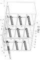
FIG. 2 is a partial diagram of the cabinet system according to the first embodiment of the present invention, -
FIG. 3 is a partial exploded diagram of a first furniture assembly according to the first embodiment of the present invention, -
FIG. 4 is a partial assembling diagram of the first furniture assembly according to the first embodiment of the present invention, -
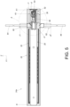
FIG. 5 is a diagram of the first furniture assembly as a second object is located at a retracted position relative to a first object according to the first embodiment of the present invention, -
FIG. 6 is an enlarged diagram of an A portion of the first furniture assembly shown inFIG. 5 according to the first embodiment of the present invention, -
FIG. 7 is a diagram of the first furniture assembly as the second object is located at an extended position and a working member is located at an engaging position according to the first embodiment of the present invention, -
FIG. 8 is an enlarged diagram of a B portion of the first furniture assembly shown inFIG. 7 according to the first embodiment of the present invention, -
FIG. 9 is a diagram illustrating the first furniture assembly locks a second furniture assembly and a third furniture assembly according to the first embodiment of the present invention, -
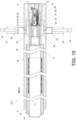
FIG. 10 is a diagram of the first furniture assembly as the second object is displaced along a retracting direction to drive the working member to move from the engaging position according to the first embodiment of the present invention, -
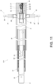
FIG. 11 is a diagram of the first furniture assembly as the second object is located at the extended position and the working member is located at an initial position according to the first embodiment of the present invention, -
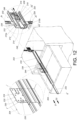
FIG. 12 is a partial diagram of a furniture assembly as a second object is located at an extended position and a working member is located at an engaging position according to a second embodiment of the present invention, -
FIG. 13 is a partial diagram of the furniture assembly as the second object is located at the extended position and the working member is located at an initial position according to the second embodiment of the present invention, and -
FIG. 14 is a partial diagram of the furniture assembly as the second object is located at a retracted position and the working member is located at the initial position as according to the second embodiment of the present invention. - In the following detailed description of the preferred embodiments, reference is made to the accompanying drawings which form a part hereof, and in which is shown by way of illustration specific embodiments in which the invention may be practiced. In this regard, directional terminology, such as "top", "bottom", "left", "right", "front", "back", etc., is used with reference to the orientation of the Figure(s) being described. The members of the present invention can be positioned in a number of different orientations. As such, the directional terminology is used for purposes of illustration and is in no way limiting. Accordingly, the drawings and descriptions will be regarded as illustrative in nature and not as restrictive. Also, if not specified, the term "connect" is intended to mean either an indirect or direct mechanical connection. Thus, if a first device is connected to a second device, that connection may be through a direct mechanical connection, or through an indirect mechanical connection via other devices and connections.
- As shown in
FIG. 1 , a cabinet system includes acabinet body 20 and a plurality of drawers, e.g., afirst drawer 22a, asecond drawer 22b, athird drawer 22c and afourth drawer 22d, arranged on thecabinet body 20 along a vertical direction and/or a transverse direction. - As shown in
FIG. 2 , the cabinet system further includes a plurality of furniture assemblies, e.g., afirst furniture assembly 24a, asecond furniture assembly 24b, athird furniture assembly 24c and afourth furniture assembly 24d, arranged on thecabinet body 20 and configured to support the plurality of drawers, e.g., thefirst drawer 22a, thesecond drawer 22b, thethird drawer 22c and thefourth drawer 22d, respectively. Thefirst furniture assembly 24a, thesecond furniture assembly 24b, thethird furniture assembly 24c and thefourth furniture assembly 24d can have similar structures. Each of thefirst furniture assembly 24a, thesecond furniture assembly 24b, thethird furniture assembly 24c and thefourth furniture assembly 24d includes afirst object 26 and asecond object 28 displaceable relative to thefirst object 26 along a longitudinal direction. In this embodiment, by way of example, each of thefirst object 26 and thesecond object 28 can be a slide rail. The longitudinal direction can be defined by a length direction or a displacing direction of the slide rail and parallel to an X axis. The transverse direction can be defined by a lateral direction or a width direction of the slide rail and parallel to a Y axis. The vertical direction can be defined by a height direction of the slide rail and parallel to a Z axis. - Preferably, each of the
first furniture assembly 24a, thesecond furniture assembly 24b, thethird furniture assembly 24c and thefourth furniture assembly 24d further includes athird object 30 movably mounted between thefirst object 26 and thesecond object 28 and for extending a displacement of thesecond object 28 relative to thefirst object 26. In this embodiment, by way of example, thefirst object 26, thesecond object 28 and thethird object 30 can form a three-section slide rail assembly, and thefirst object 26, thesecond object 28 and thethird object 30 can be a fixed rail, a movable rail and a middle rail of the three-section slide rail assembly, respectively. Understandably, in another embodiment, the third rail can be omitted, and the first object and the second object can form a two-section slide rail assembly. - Preferably, the
first objects 26 of thefirst furniture assembly 24a, thesecond furniture assembly 24b, thethird furniture assembly 24c and thefourth furniture assembly 24d are mounted or fixed on thecabinet body 20. The second objects 28 of thefirst furniture assembly 24a, thesecond furniture assembly 24b, thethird furniture assembly 24c and thefourth furniture assembly 24d are configured to support thefirst drawer 22a, thesecond drawer 22b, thethird drawer 22c and thefourth drawer 22d, respectively. In such a way, thefirst drawer 22a, thesecond drawer 22b, thethird drawer 22c and thefourth drawer 22d can be retracted or opened relative to thecabinet body 20 by thefirst furniture assembly 24a, thesecond furniture assembly 24b, thethird furniture assembly 24c and thefourth furniture assembly 24d, respectively. For example, when thesecond object 28 of thefirst furniture assembly 24a is retracted relative to thefirst object 26 of thefirst furniture assembly 24a, thefirst drawer 22a is retracted relative to thecabinet body 20. Alternatively, when thesecond object 28 of thefourth furniture assembly 24d is retracted relative to thefirst object 26 of thefourth furniture assembly 24d, thefourth drawer 22d is retracted relative to thecabinet body 20. - As for the
first furniture assembly 24a, thefirst furniture assembly 24a is located between thesecond furniture assembly 24b and thethird furniture assembly 24c along the vertical direction, and thefirst furniture assembly 24a further includes aninterlock mechanism 32 configured to cooperate with thesecond furniture assembly 24b and thethird furniture assembly 24c. When thesecond object 28 of thefirst furniture assembly 24a is opened relative to thefirst object 26 of thefirst furniture assembly 24a, theinterlock mechanism 32 can be retained in a locking state, such that thesecond objects 28 of thesecond furniture assembly 24b and thethird furniture assembly 24c are prevented from being opened relative to the correspondingfirst objects 26 of thesecond furniture assembly 24b and thethird furniture assembly 24c. In other words, theinterlock mechanism 32 can achieve an interlock function for preventing thesecond drawer 22b and thethird drawer 22c from being opened relative to thecabinet body 20 when thefirst drawer 22a is opened relative to thecabinet body 20. - Besides, as shown in
FIG. 3 andFIG. 4 , thefirst furniture assembly 24a further includes a self-closingdevice 34, an aidingmember 36 and anactuating part 38. - As shown in
FIG. 3 andFIG. 4 , thefirst object 26 includes afirst wall 40a, asecond wall 40b and alongitudinal wall 42 connected between thefirst wall 40a and thesecond wall 40b of thefirst object 26. Thefirst wall 40a, thesecond wall 40b and thelongitudinal wall 42 of thefirst object 26 cooperatively define afirst channel 44 of thefirst object 26. Thefirst object 26 includes a front end portion f1 and a rear end portion r1. - The
third object 30 is at least partially movably mounted inside thefirst channel 44 of thefirst object 26. Thethird object 30 includes asecond channel 50. Thethird object 30 includes a front end portion f3 and a rear end portion r3. - The
second object 28 is at least partially mounted inside thesecond channel 50 of thethird object 30. Thesecond object 28 includes a front end portion f2 and a rear end portion r2. - The self-closing
device 34 is arranged on thefirst object 26. For example, the self-closingdevice 34 can be arranged adjacent to the rear end portion r1 of thefirst object 26. The self-closingdevice 34 includes abase 52, a workingmember 54 and aresilient member 56. Thebase 52 is detachably or fixedly connected to thelongitudinal wall 42 of thefirst object 26. In this embodiment, by way of example, thebase 52 can be fixedly connected to thelongitudinal wall 42 of thefirst object 26. The workingmember 54 is movable relative to thebase 52. Theresilient member 56 is configured to drive the workingmember 54 to move back to an initial position X1 as shown inFIG. 4 . - Preferably, the
base 52 includes a receivingspace 62. Theresilient member 56 is detachably mounted inside the receivingspace 62 of thebase 52. The workingmember 54 includes acorresponding part 64 configured to abut against theresilient member 56. For example, theresilient member 56 can be a spring. Theresilient member 56 can be detached from the receivingspace 62 and replaced by another resilient member with an elastic coefficient different from an elastic coefficient of theresilient member 56 according to practical demands. - Preferably, the working
member 54 is movably mounted on thebase 52. Furthermore, the base 52 further includes alongitudinal part 66 and a bendingpart 68. Thelongitudinal part 66 has a predetermined longitudinal length. The bendingpart 68 extends from thelongitudinal part 66 and is bent from thelongitudinal part 66. As shown inFIG. 6 , the workingmember 54 includes a supportingfeature 70, such that the workingmember 54 is movable along thelongitudinal part 66 and the bendingpart 68 by the supportingfeature 70. Besides, the base 52 further includes a blockingwall 72 configured to block the supportingfeature 70 for stopping the workingmember 54 at a position, e.g., the initial position X1. - Preferably, the working
member 54 further includes a workingpart 74 configured to cooperate with the actuatingpart 38. In this embodiment, by way of example, the workingpart 74 can be a protrusion. However, the present invention is not limited to this embodiment. - The aiding
member 36 is movable relative to thebase 52. In this embodiment, by way of example, the aidingmember 36 can be movably mounted on thebase 52. Preferably, thebase 52 includes alongitudinal track 76, and the aidingmember 36 includes a cooperatingfeature 78 movably mounted on thelongitudinal track 76. In this embodiment, by way of example, the cooperatingfeature 78 can be configured to embrace thelongitudinal track 76, such that the aidingmember 36 is movable relative to thebase 52 along thelongitudinal track 76. - The
interlock mechanism 32 is arranged on thefirst object 26. For example, theinterlock mechanism 32 can be arranged adjacent to the rear end portion r1 of thefirst object 26. Theinterlock mechanism 32 includes at least one locking member, e.g., afirst locking member 80 and asecond locking member 82. Thefirst locking member 80 and thesecond locking member 82 are movably mounted on thefirst object 26, and the first lockingmember 80 and thesecond locking member 82 are movable relative to thefirst wall 40a and thesecond wall 40b of thefirst object 26, respectively. - One of the aiding
member 36 and the first lockingmember 80 includes a first guidingpart 84. In this embodiment, by way of example, the aidingmember 36 includes the first guidingpart 84. Preferably, the first lockingmember 80 includes a firstauxiliary guiding feature 86 configured to cooperate with the first guidingpart 84. As shown inFIG. 4 , in this embodiment, by way of example, the first guidingpart 84 and the firstauxiliary guiding feature 86 can be inclined surfaces or arc surfaces. However, the present invention is not limited to this embodiment. Similarly, one of the aidingmember 36 and thesecond locking member 82 includes a second guidingpart 88. In this embodiment, by way of example, the aidingmember 36 includes the second guidingpart 88. Preferably, thesecond locking member 82 includes a secondauxiliary guiding feature 90 configured to cooperate with the second guidingpart 88. As shown inFIG. 4 , in this embodiment, by way of example, the second guidingpart 88 and the secondauxiliary guiding feature 90 can be inclined surfaces or arc surfaces. However, the present invention is not limited to this embodiment. - Preferably, the aiding
member 36 further includes abuffering part 92. In this embodiment, by way of example, thebuffering part 92 can be a resilient arm. However, the present invention is not limited to this embodiment. - Preferably, as shown in
FIG. 2 , the first lockingmember 80 of thefirst furniture assembly 24a is connected to afirst rod 94 connected to asecond locking member 96 of thesecond furniture assembly 24b. Besides, thesecond locking member 82 of thefirst furniture assembly 24a is connected to asecond rod 98 connected to afirst locking member 100 of thethird furniture assembly 24c. - Preferably, in this embodiment, the actuating
part 38 is arranged on thesecond object 28. For example, the actuatingpart 38 can be integrally connected to thesecond object 28 and located adjacent to the rear end portion r2 of thesecond object 28. Preferably, the actuatingpart 38 includes an engagingsection 102 and aguiding section 104 adjacent to the engagingsection 102. For example, the guidingsection 104 can be an arc surface or an inclined surface. - As shown in
FIG. 5 andFIG. 6 , thesecond object 28 is located at a retracted position R relative to thefirst object 26, and theactuating part 38 engages with the workingmember 54, e.g., the engagingsection 102 of theactuating part 38 engages with the workingpart 74 of the workingmember 54. Besides, as shown inFIG. 5 andFIG. 6 , the workingmember 54 is located at the initial position X1 relative to thebase 52, and the aidingmember 36 is located at a first predetermined position K1 relative to thebase 52. In addition, as shown inFIG. 5 andFIG. 6 , the first lockingmember 80 is located at an unlocking position J1 where the firstauxiliary guiding feature 86 of the first lockingmember 80 is located at a position corresponding to the first guidingpart 84 of the aidingmember 36, and thesecond locking member 82 is located at a locking position J2' where the secondauxiliary guiding feature 90 of thesecond locking member 82 is located at a position not corresponding to the second guidingpart 88 of the aidingmember 36, e.g., the secondauxiliary guiding feature 90 of thesecond locking member 82 is misaligned with the second guidingpart 88 of the aidingmember 36. - Preferably, as shown in
FIG. 5 , a length of thefirst object 26 is substantially identical to a length of thesecond object 28, and a length of thethird object 30 is less than the length of thefirst object 26 or the length of thesecond object 28. When thesecond object 28 is located at the retracted position R relative to thefirst object 26, the self-closingdevice 34 and the aidingmember 36 are located between the rear end portion r3 of thethird object 30 and the rear end portion r1 of thefirst object 26. - Preferably, as shown in
FIG. 6 , a portion of the first lockingmember 80 is located inside thefirst channel 44 of thefirst object 26, and the first lockingmember 80 includes afirst restraining section 106 configured to abut against an inner side of thefirst wall 40a of thefirst object 26 for preventing an excessive movement of the first lockingmember 80. Similarly, a portion of thesecond locking member 82 is located inside thefirst channel 44 of thefirst object 26, and thesecond locking member 82 includes asecond restraining section 108 configured to abut against an inner side of thesecond wall 40b of thefirst object 26 for preventing an excessive movement of thesecond locking member 82. - Preferably, the
base 52 is configured to support the first lockingmember 80 for retaining the first lockingmember 80 at the unlocking position J1. Besides, thesecond restraining section 108 of thesecond locking member 82 and the inner side of thesecond wall 40b of thefirst object 26 are configured to abut against each other for retaining thesecond locking member 82 at the locking position J2'. - When the
second object 28 is displaced relative to thefirst object 26 from the retracted position R toward an extended position E along an opening direction D1, the actuatingpart 38 drives the workingmember 54 to move from the initial position X1 as shown inFIG. 6 to an engaging position X2 as shown inFIG. 7 andFIG. 8 . For example, when the workingmember 54 is located at the engaging position X2 as shown inFIG. 8 , the supportingfeature 70 of the workingmember 54 engages with the bendingpart 68 of thebase 52, and the workingmember 54 is tilted. Besides, when theactuating part 38 drives the workingmember 54 to move from the initial position X1 as shown inFIG. 6 to the engaging position X2 as shown inFIG. 7 andFIG. 8 , theresilient member 56 is resiliently deformed to generate a self-closing resilient force F as shown inFIG. 8 along a retracting direction D2 and the aidingmember 36 is driven to move from the first predetermined position K1 as shown inFIG. 6 to a second predetermined position K2 as shown inFIG. 7 andFIG. 8 . During a movement of the aidingmember 36 from the first predetermined position K1 to the second predetermined position K2, the aidingmember 36 drives the first lockingmember 80 to move from the unlocking position J1 as shown inFIG. 6 to a locking position J2 as shown inFIG. 7 andFIG. 8 along the vertical direction, e.g., a height direction U, by an abutment of the first guidingpart 84 and the firstauxiliary guiding feature 86. - As shown in
FIG. 8 , when the aidingmember 36 is located at the second predetermined position K2, the aidingmember 36 can support the first lockingmember 80 for retaining the first lockingmember 80 at the locking position J2. Moreover, as shown inFIG. 8 , when the aidingmember 36 is located at the second predetermined position K2, the aidingmember 36 can press thesecond locking member 82 for retaining thesecond locking member 82 at the locking position J2'. In addition, as shown inFIG. 7 andFIG. 8 , during a movement of the workingmember 54 from the initial position X1 to the engaging position X2, the workingpart 74 of the workingmember 54 moves along the guidingsection 104 of theactuating part 38 to disengage from the engagingsection 102 of theactuating part 38. - Preferably, when the
second object 28 is displaced from the retracted position R toward the extended position E along the opening direction D1, the workingmember 54 is driven by the actuatingpart 38, so as to drive the aidingmember 36 to move from the first predetermined position K1 as shown inFIG. 6 to the second predetermined position K2 as shown inFIG. 8 along the opening direction D1 by the workingmember 54. - As shown in
FIG. 9 , when thesecond object 28 of thefirst furniture assembly 24a is located at the extended position E relative to the correspondingfirst object 26 and the aidingmember 36 is located at the second predetermined position K2, the aidingmember 36 retains the first lockingmember 80 and thesecond locking member 82 at the locking positions J2, J2' respectively for preventing opening movements of the othersecond objects 28, e.g., thesecond objects 28 of thesecond furniture assembly 24b and thethird furniture assembly 24c, relative to the correspondingfirst objects 26 along the opening direction D1, so as to prevent the corresponding drawers, e.g., thesecond drawer 22b and thethird drawer 22c, from being opened relative to thecabinet body 20. - Furthermore, two ends of the
first rod 94 are connected to the first lockingmember 80 of thefirst furniture assembly 24a and thesecond locking member 96 of thesecond furniture assembly 24b, respectively. When thesecond object 28 of thesecond furniture assembly 24b is located at the retracted position R relative to the correspondingfirst object 26, an actuating part arranged on thesecond object 28 of thesecond furniture assembly 24b engages with a workingmember 110, e.g., a workingpart 112 of the workingmember 110 of thesecond furniture assembly 24b. When the first lockingmember 80 of thefirst furniture assembly 24a is retained at the locking position J2, a secondauxiliary guiding feature 114 of thesecond locking member 96 of thesecond furniture assembly 24b can block asecond guiding part 118 of an aidingmember 116 of thesecond furniture assembly 24b to prevent the aidingmember 116 of thesecond furniture assembly 24b from moving along the opening direction D1, so as to prevent thesecond object 28 of thesecond furniture assembly 24b from being opened relative to the correspondingfirst object 26 along the opening direction D1. - Similarly, two ends of the
second rod 98 are connected to thesecond locking member 82 of thefirst furniture assembly 24a and thefirst locking member 100 of thethird furniture assembly 24c, respectively. When thesecond object 28 of thethird furniture assembly 24c is located at the retracted position R relative to the correspondingfirst object 26, an actuating part arranged on thesecond object 28 of thethird furniture assembly 24c engages with a workingmember 120, e.g., a workingpart 122 of the workingmember 120 of thethird furniture assembly 24c. When thesecond locking member 82 of thefirst furniture assembly 24a is retained at the locking position J2', a firstauxiliary guiding feature 124 of thefirst locking member 100 of thethird furniture assembly 24c can block a first guidingpart 128 of an aidingmember 126 of thethird furniture assembly 24c to prevent the aidingmember 126 of thethird furniture assembly 24c from moving along the opening direction D1, so as to prevent thesecond object 28 of thethird furniture assembly 24c from being opened relative to the correspondingfirst object 26 along the opening direction D 1. - From the above, understandably, when the
second object 28 of thefirst furniture 24a, is opened relative to the correspondingfirst object 26, the aidingmember 36 in the second predetermined position K2 retains theinterlock mechanism 32 in the locking state to achieve the interlock function for preventing thesecond objects 28 of thesecond furniture assembly 24b and thethird furniture assembly 24c from being opened relative to the corresponding first objects 26. - When it is desired to terminate the interlock function, it has to move the aiding
member 36 from the second predetermined position K2 as shown inFIG. 10 back to the first predetermined position K1 as shown inFIG. 5 andFIG. 6 . Furthermore, the aidingmember 36 can be driven to move from the second predetermined position K2 as shown inFIG. 10 to the first predetermined position K1 as shown inFIG. 5 andFIG. 6 during a displacement of thesecond object 28 of thefirst furniture assembly 24a relative to the correspondingfirst object 26 from the extended position E toward the retracted position R along the retracting direction D2. As shown inFIG. 5 andFIG. 6 , when the aidingmember 36 is located at the first predetermined position K1, the aidingmember 36 does not support the first lockingmember 80, such that the first lockingmember 80 can return back to the unlocking position J1. Besides, as shown inFIG. 5 andFIG. 6 , when the aidingmember 36 is located at the first predetermined position K1, the aidingmember 36 does not press thesecond locking member 82 for allowing thesecond locking member 82 to move from the locking position J2'. In other words, when the aidingmember 36 is located at the first predetermined position K1, the interlock function is terminated. Besides, during the displacement of thesecond object 28 of thefirst furniture assembly 24a relative to the correspondingfirst object 26 from the extended position E toward the retracted position R along the retracting direction D2, the actuatingpart 38 arranged on thesecond object 28 of thefirst furniture assembly 24a engages with the workingmember 54 again. For example, during the displacement of thesecond object 28 of thefirst furniture assembly 24a relative to the correspondingfirst object 26 from the extended position E toward the retracted position R along the retracting direction D2, the workingpart 74 of the workingmember 54 can be driven to move along the guidingsection 104 of theactuating part 38 to engage with the engagesection 102 of theactuating part 38, so as to drive the workingmember 54 to move from the engaging position X2 to disengage the supportingfeature 70 of the workingmember 54 from the bendingpart 68 of thebase 52. In such a way, the workingmember 54 can move back to the initial position X1 in response to the self-closing resilient force F provided by theresilient member 56 along the retracting direction D2 for driving thesecond object 28 of thefirst furniture assembly 24a back to the retracted position R as shown inFIG. 5 andFIG. 6 , so as to achieve a self-closing function. - Preferably, during the displacement of the
second object 28 of thefirst furniture assembly 24a from the extended position E toward the retracted position R along the retracting direction D2, thethird object 30 of thefirst furniture assembly 24a is displaced along the retracting direction D2 as shown inFIG. 10 . Thethird object 30 of thefirst furniture assembly 24a can drive the aidingmember 36 from the second predetermined position K2 as shown inFIG. 10 back to the first predetermined position K1 as shown inFIG. 5 andFIG. 6 . For example, the rear end portion r3 of thethird object 30 of thefirst furniture assembly 24a can abut against the bufferingpart 92 of the aidingmember 36, such that thethird object 30 of thefirst furniture assembly 24a drives the aidingmember 36 from the second predetermined position K2 as shown inFIG. 10 back to the first predetermined position K1 as shown inFIG. 5 andFIG. 6 by an abutment of the rear end portion r3 of thethird object 30 and thebuffering part 92 of the aidingmember 36 of thefirst furniture assembly 24a during a movement of the workingmember 54 back to the initial position X1 in response to the self-closing resilient force F provided by theresilient member 56 along the retracting direction D2 for driving thesecond object 28 of thefirst furniture assembly 24a back to the retracted position R as shown inFIG. 5 andFIG. 6 . Understandably, in another embodiment, the second object can be configured to abut against the aiding member to drive the aiding member back to the first predetermined position. - As shown in
FIG. 11 , if thesecond object 28 of thefirst furniture assembly 24a is located at the extended position E relative to the correspondingfirst object 26 and the supportingfeature 70 of the workingmember 54 is driven to disengage from the bendingpart 68 by an unexpected force, e.g., due to a collision or a vibration, the workingmember 54 moves back to the initial position X1 along the retracting direction D2 in response to the self-closing resilient force F provided by theresilient member 56, which causes a malfunction of the self-closingdevice 34. However, when the workingmember 54 moves back to the initial position X1, since the aidingmember 36 is still located at the second predetermined position K2 for retaining the first lockingmember 80 and thesecond locking member 82 at the locking positions J2, J2', theinterlock mechanism 32 still can achieve the interlock function. When it is desired to terminate the interlock function, the aidingmember 36 can be moved from the second predetermined position K2 as shown inFIG. 11 to the first predetermined position K1 by the displacement of thesecond object 28 of thefirst furniture assembly 24a from the extended position E toward the retracted position R along the retracting direction D2. - When the malfunction of the self-closing
device 34 occurs, another actuatingpart 39 arranged on thesecond object 28 of thefirst furniture assembly 24a can be utilized to engage with the workingpart 74 of the workingmember 54 for driving the workingmember 54 from the initial position X1 to the engaging position X2 along the opening direction D1, so as to achieve a functional recovery of the self-closingdevice 34. - As shown in
FIG. 12 , different from the first embodiment, a furniture assembly of the second embodiment includes afirst object 202 and asecond object 204, wherein the furniture assembly can be a cabinet system, and thefirst object 202 and thesecond object 204 can be a cabinet body and a drawer of the cabinet system, respectively. - Furthermore, the furniture assembly of the second embodiment further includes a first
fitting member 208, and a self-closing device is arranged on thefirst object 202 by the firstfitting member 208. In this embodiment, by way of example, the firstfitting member 208 can be detachably connected to thefirst object 202. However, the present invention is not limited to this embodiment. Understandably, the firstfitting member 208 can be considered as a part of thefirst object 202 because of connection of the firstfitting member 208 and thefirst object 202. The firstfitting member 208 includes afirst wall 210a, asecond wall 210b and alongitudinal wall 212 connected between thefirst wall 210a and thesecond wall 210b of the firstfitting member 208, and thefirst wall 210a, thesecond wall 210b and thelongitudinal wall 212 of the firstfitting member 208 cooperatively define anauxiliary channel 214 of the firstfitting member 208. - The self-closing device includes a
base 216, a workingmember 218 and aresilient member 220, and an aidingmember 222. Thebase 216 is connected to thelongitudinal wall 212 of the firstfitting member 208. The workingmember 218 and the aidingmember 222 are movable relative to thebase 216. Other details of thebase 216, the workingmember 218, theresilient member 220 and the aidingmember 222 of this embodiment are identical to the ones of thebase 52, the workingmember 54, theresilient member 56 and the aidingmember 36 of the first embodiment. Detailed description is omitted herein for simplicity. - Furthermore, an interlock mechanism is arranged on the
first object 202 by the firstfitting member 208. The interlock mechanism includes at least one locking member, e.g., afirst locking member 226 and asecond locking member 228. Thefirst locking member 226 and thesecond locking member 228 are movably mounted on the firstfitting member 208. Thefirst locking member 226 and thesecond locking member 228 are movable relative to thefirst wall 210a and thesecond wall 210b of the firstfitting member 208, respectively. - Besides, the furniture assembly of the second embodiment further includes a second
fitting member 230 mounted on thesecond object 204. In this embodiment, the secondfitting member 230 can be detachably connected to thesecond object 204. However, the present invention is not limited to this embodiment. Understandably, the secondfitting member 230 can be considered as a part of thesecond object 204 because of connection of the secondfitting member 230 and thesecond object 204. The secondfitting member 230 includes amain body part 232, anactuating part 234 and apredetermined part 236. Themain body part 232 includes a front end portion f' and a rear end portion r'. Theactuating part 234 is arranged on themain body part 232 and located adjacent to the rear end portion r' of themain body part 232. Thepredetermined part 236 is bent from the front end portion f' of themain body part 232. In this embodiment, by way of example, thepredetermined part 234 can be bent from the front end portion f' of themain body part 232 and is substantially perpendicular to the front end portion f' of themain body part 232. From the above, understandably, theactuating part 234 can be considered to be detachably arranged on thesecond object 204 by the secondfitting member 230. Other details of theactuating part 234 of this embodiment are identical to the ones of theactuating part 38 of the first embodiment. Detailed description is omitted herein for simplicity. - Preferably, the furniture assembly of the second embodiment further includes an auxiliary supporting
device 238. The auxiliary supportingdevice 238 includes a firstauxiliary rail 240 and a secondauxiliary rail 242 displaceable relative to the firstauxiliary rail 240 along the longitudinal direction. The firstauxiliary rail 240 is mounted on thefirst object 202, and the secondauxiliary rail 242 is configured to support thesecond object 204. - Preferably, the auxiliary supporting
device 238 further includes a thirdauxiliary rail 244 movably mounted between the firstauxiliary rail 240 and the secondauxiliary rail 242 for extending a displacement of the secondauxiliary rail 242 relative to the firstauxiliary rail 240. In other words, in this embodiment, by way of example, the auxiliary supportingdevice 238 can be a three-section slide rail assembly. - Similar to the first embodiment, in this embodiment, when the
second object 204 is displaced from the retracted position toward an extended position E' along the opening direction D1, theactuating part 234 drives the workingmember 218 to move from an initial position X1' to an engaging position X2', such that theresilient member 220 is resiliently deformed to generate a self-closing resilient force F' along the retracting direction D2 and the aidingmember 222 is driven to move from a first predetermined position K1' to a second predetermined position K2'. When thesecond object 204 is located at the extended position E' relative to thefirst object 202, the aidingmember 222 located at the second predetermined position K2' retains thefirst locking member 226 and thesecond locking member 28 at the locking positions Jb, Jb' respectively for preventing opening movements of second objects of other furniture assemblies relative to corresponding first objects. - As shown in
FIG. 13 andFIG. 12 , similar to the first embodiment, in this embodiment, if thesecond object 204 is located at the extended position E' and the workingmember 218 disengages from the base 216 by an unexpected force, e.g., due to a collision or a vibration, and then moves back to the initial position X1' along the retracting direction D2 in response to the self-closing resilient force F provided by theresilient member 220, the aidingmember 222 is still located at the second predetermined position K2' for retaining thefirst locking member 226 and thesecond locking member 228 at the locking positions Jb, Jb', so as to prevent a malfunction of the interlock mechanism. - As shown in
FIG. 14, FIG. 14 illustrates the secondfitting member 230 and the secondauxiliary rail 242 but does not illustrate thesecond object 204. As shown inFIG. 12 and FIG. 12 , similar to the first embodiment, in this embodiment, during a displacement of thesecond object 204 from the extended position E' toward the retracted position R' along the retracting direction D2, theactuating part 234 of the secondfitting member 230 engages with the working part of the workingmember 218, such that the workingmember 218 can move from the engaging position X2' as shown inFIG. 12 to the initial position X1' as shown inFIG. 14 in response to the self-closing resilient force F' for driving thesecond object 204 to move back to the retracted position R' as shown inFIG. 14 . Furthermore, during the displacement of thesecond object 204 from the extended position E' toward the retracted position R' along the retracting direction D2, thepredetermined part 236 of the secondfitting member 230 can abut against thebuffering part 248 of the aidingmember 222 to drive the aidingmember 222 to move from the second predetermined position K2' as shown inFIG. 12 to the first predetermined position K1' as shown inFIG. 14 , such that the aidingmember 222 does not support thefirst locking member 226 for returning thefirst locking member 226 from the locking position Jb as shown inFIG. 12 to an unlocking position Ja as shown inFIG. 14 and the aidingmember 222 does not press thesecond locking member 228 for allowing thesecond locking member 228 to move from the locking position Jb', so as to terminate the interlock function. - In conclusion, in contrast to the prior art, the present invention includes the following characteristics.
- 1. If the
second object first object member base member member second locking member - 2. In the first embodiment, the self-closing
device 34 and the at least one locking member of theinterlock mechanism 32 are mounted on thefirst object 26, e.g., the fixed rail. In other words, in the first embodiment, the self-closingdevice 34 and the interlock mechanism are built together with the slide rail assembly. In the second embodiment, the self-closing device and the at least one locking member of the interlock mechanism are detachably mounted on thefirst object 202, e.g., the cabinet body, by the firstfitting member 208, and the self-closing device and the at least one locking member of the interlock mechanism are configured to cooperate with the secondfitting member 230 detachably mounted on thesecond object 204, e.g., the drawer. In other words, in the second embodiment, the self-closing device and the interlock mechanism are separated from the slide rail assembly, e.g., the auxiliary supportingdevice 238, and therefore, the self-closing device and interlock mechanism can be adapted to the cabinet body and the drawer of the cabinet system without any slide rail assembly. - 3. The
resilient member resilient member resilient member 56 according to practical demands. - Those skilled in the art will readily observe that numerous modifications and alterations of the device and method may be made while retaining the teachings of the invention. Accordingly, the above disclosure should be construed as limited only by the metes and bounds of the appended claims.
Claims (15)
- A furniture assembly (24a) comprising:a first object (26, 202); anda second object (28, 204) displaceable relative to the first object (26, 202);andcharacterized by:a self-closing device (34) arranged on the first object (26, 202), the self-closing device (34) comprising:a base (52, 216);a working member (54, 218) movable relative to the base (52, 216); anda resilient member (56, 220);an aiding member (36, 222) movable relative to the base (52, 216) of the self-closing device (34);an interlock mechanism (32) arranged on the first object (26, 202), and the interlock mechanism (32) comprising at least one locking member; andan actuating part (38, 234) arranged on the second object (28, 204);wherein when the second object (28, 204) is displaced from a retracted position (R, R') toward an extended position (E, E'), the actuating part (38, 234) drives the working member (54, 218) to move from an initial position (X1, X1') to an engaging position (X2, X2'), and when the actuating part (38, 234) drives the working member (54, 218) to move from the initial position (X1, X1') to the engaging position (X2, X2'), the resilient member (56, 220) generates a self-closing resilient force (F, F') and the aiding member (36, 222) is driven to move from a first predetermined position (K1, K1') to a second predetermined position (K2, K2');wherein when the second object (28, 204) is located at the extended position (E, E') and the working member (54, 218) returns to the initial position (X1, X1') from the engaging position (X2, X2') in response to the self-closing resilient force (F, F') provided by the resilient member (56, 220), the aiding member (36, 222) is located at the second predetermined position (K2, K2') to retain the at least one locking member of the interlock mechanism (32) at a locking position.
- The furniture assembly (24a) of claim 1, characterized in that when the second object (28, 204) is displaced from the retracted position (R, R') toward the extended position (E, E'), the working member (54, 218) is driven by the actuating part (38, 234), so as to drive the aiding member (36, 222) to move from the first predetermined position (K1, K1') to the second predetermined position (K2, K2') by the working member (54, 218).
- The furniture assembly (24a) of any of claims 1 and 2, characterized in that the base (52, 216) is connected to the first object (26, 202), and the working member (54, 218) and the aiding member (36, 222) are movably mounted on the base (52, 216).
- The furniture assembly (24a) of any of claims 1 to 3, characterized in that the first object (26, 202) comprises a front end portion (f1) and a rear end portion (r1), and the interlock mechanism (32) is arranged adjacent to the rear end portion (r1) of the first object (26, 202).
- The furniture assembly (24a) of any of claims 1 to 4, characterized in that when the second object (28, 204) is displaced from the extended position (E, E') toward the retracted position (R, R'), the actuating part (38, 234) engages with the working member (54, 218), such that when the working member (54, 218) returns to the initial position (X1, X1') from the engaging position (X2, X2') in response to the self-closing resilient force (F, F') provided by the resilient member (56, 220), the working member (54, 218) drives the second object (28, 204) to move back to retracted position (R, R') by an engagement of the actuating part (38, 234) and the working member (54, 218), so as to drive the aiding member (36, 222) to move from the second predetermined position (K2, K2') to the first predetermined position (K1, K1').
- The furniture assembly (24a) of any of claims 1 to 5, characterized in that the first object (26) and the second object (28) are a fixed rail and a movable rail of a slide rail assembly, respectively.
- The furniture assembly (24a) of claim 6, characterized in that the aiding member (36) is driven to move from the second predetermined position (K2) to the first predetermined position (K1) during a displacement of the second object (28) from the extended position (E) toward the retracted position (R).
- The furniture assembly (24a) of claim 7, further characterized by a third object (30) movably mounted between the first object (26) and the second object (28), the third object (30) being a middle rail of the slide rail assembly, and when the second object (28) is displaced from the extended position (E) toward the retracted position (R), the aiding member (36) being driven by the third object (30) to move from the second predetermined position (K2) to the first predetermined position (K1).
- The furniture assembly (24a) of claim 8, characterized in that a length of the third object (30) is less than a length of the first object (26).
- The furniture assembly of any of claims 1 to 5, characterized in that the first object (202) and the second object (204) are a cabinet and a drawer, respectively.
- The furniture assembly of claim 10, characterized in that a fitting member (230) is arranged on the second object (204), the fitting member (230) comprises the actuating part (234) and a predetermined part (236), and during a displacement of the second object (204) from the extended position (E') toward the retracted position (R'), the actuating part (234) engages with the working member (218), such that when the working member (218) returns to the initial position (X1') from the engaging position (X2') in response to the self-closing resilient force (F') provided by the resilient member (220), the working member (218) drives the second object (204) to move back to retracted position (R') by an engagement of the actuating part (234) and the working member (218), so as to drive the aiding member (222) to move from the second predetermined position (K2') to the first predetermined position (K1') by the fitting member (230).
- The furniture assembly of claim 11, characterized in that the fitting member (230) further comprises a main body part (232), the actuating part (234) is arranged on the main body part (232) and located adjacent to a rear end portion (r') of the main body part (232), and the predetermined part (236) is bent from a front end portion (f') of the main body part (232).
- The furniture assembly of claim 12, further characterized by an auxiliary supporting device (238) separated from the self-closing device and the interlock mechanism, and the auxiliary supporting device comprises a first auxiliary rail (240) mounted on the first object (202) and a second auxiliary rail (242) displaceable relative to the first auxiliary rail (240) and configured to support the second object (204).
- The furniture assembly of claim 13, characterized in that the auxiliary supporting device further comprises a third auxiliary rail (244) movably mounted between the first auxiliary rail (240) and the second auxiliary rail (242) for extending a displacement of the second auxiliary rail (242) relative to the first auxiliary rail (240).
- The furniture assembly (24a) of any of claims 1 to 14, characterized in that the resilient member (56, 220) is detachably mounted on the base (52, 216).
Applications Claiming Priority (1)
| Application Number | Priority Date | Filing Date | Title |
|---|---|---|---|
| TW112117998A TWI848703B (en) | 2023-05-12 | 2023-05-12 | Furniture assembly |
Publications (2)
| Publication Number | Publication Date |
|---|---|
| EP4461160A1 true EP4461160A1 (en) | 2024-11-13 |
| EP4461160B1 EP4461160B1 (en) | 2025-10-22 |
Family
ID=88600419
Family Applications (1)
| Application Number | Title | Priority Date | Filing Date |
|---|---|---|---|
| EP23206636.5A Active EP4461160B1 (en) | 2023-05-12 | 2023-10-30 | Furniture assembly |
Country Status (4)
| Country | Link |
|---|---|
| US (1) | US12305428B2 (en) |
| EP (1) | EP4461160B1 (en) |
| JP (1) | JP7647004B2 (en) |
| TW (1) | TWI848703B (en) |
Families Citing this family (1)
| Publication number | Priority date | Publication date | Assignee | Title |
|---|---|---|---|---|
| CN220889859U (en) * | 2023-08-28 | 2024-05-03 | 昆山湖华金属制品有限公司 | Interlink lock mechanism for multi-layer drawer furniture |
Citations (2)
| Publication number | Priority date | Publication date | Assignee | Title |
|---|---|---|---|---|
| US7320507B2 (en) | 2001-10-05 | 2008-01-22 | Accuride International Limited | Rear interlock |
| US20090015115A1 (en) * | 2004-06-09 | 2009-01-15 | Arnoldus Adriaan Van Wijk | Apparatus for controlling the operation of drawers |
Family Cites Families (19)
| Publication number | Priority date | Publication date | Assignee | Title |
|---|---|---|---|---|
| US6296332B1 (en) | 1996-07-12 | 2001-10-02 | Accuride International, Inc. | File interlock system and mechanism |
| US20080061663A1 (en) | 2006-09-08 | 2008-03-13 | Tsung-Che Wu | Drawer slide module structure |
| KR101114477B1 (en) * | 2009-08-07 | 2012-02-24 | (주)세고스 | sliding apparatus with self-closing apparatus |
| TWI411416B (en) | 2011-01-21 | 2013-10-11 | King Slide Works Co Ltd | Slide interlock assembly |
| DE202015104431U1 (en) * | 2015-08-21 | 2016-11-22 | Grass Gmbh | Device for moving a furniture part and furniture |
| AT518398B1 (en) * | 2016-04-05 | 2017-10-15 | Blum Gmbh Julius | furniture drive |
| TWI616165B (en) * | 2017-03-07 | 2018-03-01 | 川湖科技股份有限公司 | Retracting mechanism for movable furniture parts |
| CN210714195U (en) * | 2019-08-08 | 2020-06-09 | 广东东荣金属制品有限公司 | A sliding rail interlocking mechanism for preventing simultaneous opening of multi-layer drawers |
| DE102020127404A1 (en) * | 2020-10-17 | 2022-04-21 | Paul Hettich Gmbh & Co. Kg | Locking device for movable furniture parts and method for locking at least one movable furniture part |
| SE547185C2 (en) * | 2021-02-12 | 2025-05-20 | Inter Ikea Sys Bv | Locking arrangement for drawers in a cabinet, a cabinet comprising such arrangement and a drawer rail |
| CN112932119B (en) * | 2021-03-17 | 2022-06-14 | 金竣企业股份有限公司 | Drawer slide rail interlocking device with additional buffering function |
| DE102021108249A1 (en) * | 2021-03-31 | 2022-10-06 | Paul Hettich Gmbh & Co. Kg | Coupling element, locking system and furniture |
| CN218438803U (en) * | 2022-07-23 | 2023-02-03 | 清远市星徽精密制造有限公司 | Simple drawer interlocking device with self-locking interlocking function |
| CN218390326U (en) * | 2022-07-23 | 2023-01-31 | 清远市星徽精密制造有限公司 | Double-lock drawer guide rail with buffering function |
| CN218355199U (en) * | 2022-09-08 | 2023-01-24 | 清远市星徽精密制造有限公司 | Self-interlocking guide rail with silencing function |
| CN116115023A (en) * | 2022-09-08 | 2023-05-16 | 清远市星徽精密制造有限公司 | Drawer interlocking guide rail with locking function |
| CN116058610A (en) * | 2023-02-16 | 2023-05-05 | 佛山市顺德区澳德里金属制品有限公司 | A drawer guide rail with interlocking function |
| TWI851287B (en) * | 2023-06-14 | 2024-08-01 | 川湖科技股份有限公司 | Furniture assembly and interlock kit thereof |
| CN116658000B (en) * | 2023-06-19 | 2026-04-03 | 广东库博精密科技集团股份有限公司 | A rotary lock linkage device suitable for multi-drawer applications |
-
2023
- 2023-05-12 TW TW112117998A patent/TWI848703B/en active
- 2023-10-05 US US18/377,290 patent/US12305428B2/en active Active
- 2023-10-30 EP EP23206636.5A patent/EP4461160B1/en active Active
- 2023-11-09 JP JP2023191613A patent/JP7647004B2/en active Active
Patent Citations (2)
| Publication number | Priority date | Publication date | Assignee | Title |
|---|---|---|---|---|
| US7320507B2 (en) | 2001-10-05 | 2008-01-22 | Accuride International Limited | Rear interlock |
| US20090015115A1 (en) * | 2004-06-09 | 2009-01-15 | Arnoldus Adriaan Van Wijk | Apparatus for controlling the operation of drawers |
Also Published As
| Publication number | Publication date |
|---|---|
| US12305428B2 (en) | 2025-05-20 |
| TWI848703B (en) | 2024-07-11 |
| JP2024163836A (en) | 2024-11-22 |
| TW202444287A (en) | 2024-11-16 |
| EP4461160B1 (en) | 2025-10-22 |
| US20240376749A1 (en) | 2024-11-14 |
| JP7647004B2 (en) | 2025-03-18 |
Similar Documents
| Publication | Publication Date | Title |
|---|---|---|
| EP4477823A1 (en) | Interlock kit and related furniture assembly | |
| EP4461160B1 (en) | Furniture assembly | |
| EP4417088A1 (en) | Slide rail mechanism | |
| EP4570126A1 (en) | Slide rail assembly | |
| EP4321053A1 (en) | Slide rail assembly | |
| EP4501174A1 (en) | Slide rail assembly | |
| EP4489537B1 (en) | Slide rail mechanism | |
| EP4393349B1 (en) | Slide rail assembly | |
| EP4403732A1 (en) | Slide rail mechanism | |
| EP4659626A1 (en) | Slide rail assembly | |
| EP3387951A1 (en) | Clutch for furniture parts | |
| EP4456686A1 (en) | Slide rail assembly | |
| EP4403733A1 (en) | Slide rail mechanism | |
| EP4420560A1 (en) | Slide rail mechanism | |
| EP4736711A1 (en) | Slide rail assembly | |
| EP4523567A1 (en) | Slide rail assembly | |
| EP4635366B1 (en) | Slide rail assembly | |
| CN112754197B (en) | Slide rail assembly | |
| US12628950B2 (en) | Slide rail assembly | |
| EP4454514B1 (en) | Slide rail assembly | |
| EP4616761B1 (en) | Slide rail mechanism | |
| CN211863782U (en) | Table tennis table sliding assembly and table tennis table | |
| JP2026079670A (en) | Slide rail assembly | |
| EP4581983A1 (en) | Slide rail mechanism | |
| JP2026085216A (en) | Slide rail mechanism |
Legal Events
| Date | Code | Title | Description |
|---|---|---|---|
| PUAI | Public reference made under article 153(3) epc to a published international application that has entered the european phase |
Free format text: ORIGINAL CODE: 0009012 |
|
| STAA | Information on the status of an ep patent application or granted ep patent |
Free format text: STATUS: THE APPLICATION HAS BEEN PUBLISHED |
|
| AK | Designated contracting states |
Kind code of ref document: A1 Designated state(s): AL AT BE BG CH CY CZ DE DK EE ES FI FR GB GR HR HU IE IS IT LI LT LU LV MC ME MK MT NL NO PL PT RO RS SE SI SK SM TR |
|
| STAA | Information on the status of an ep patent application or granted ep patent |
Free format text: STATUS: REQUEST FOR EXAMINATION WAS MADE |
|
| 17P | Request for examination filed |
Effective date: 20250326 |
|
| GRAP | Despatch of communication of intention to grant a patent |
Free format text: ORIGINAL CODE: EPIDOSNIGR1 |
|
| STAA | Information on the status of an ep patent application or granted ep patent |
Free format text: STATUS: GRANT OF PATENT IS INTENDED |
|
| RIC1 | Information provided on ipc code assigned before grant |
Ipc: A47B 97/00 20060101ALN20250430BHEP Ipc: E05B 65/464 20170101ALI20250430BHEP Ipc: A47B 88/467 20170101AFI20250430BHEP |
|
| INTG | Intention to grant announced |
Effective date: 20250516 |
|
| GRAS | Grant fee paid |
Free format text: ORIGINAL CODE: EPIDOSNIGR3 |
|
| GRAA | (expected) grant |
Free format text: ORIGINAL CODE: 0009210 |
|
| STAA | Information on the status of an ep patent application or granted ep patent |
Free format text: STATUS: THE PATENT HAS BEEN GRANTED |
|
| AK | Designated contracting states |
Kind code of ref document: B1 Designated state(s): AL AT BE BG CH CY CZ DE DK EE ES FI FR GB GR HR HU IE IS IT LI LT LU LV MC ME MK MT NL NO PL PT RO RS SE SI SK SM TR |
|
| REG | Reference to a national code |
Ref country code: CH Ref legal event code: F10 Free format text: ST27 STATUS EVENT CODE: U-0-0-F10-F00 (AS PROVIDED BY THE NATIONAL OFFICE) Effective date: 20251022 Ref country code: GB Ref legal event code: FG4D |
|
| REG | Reference to a national code |
Ref country code: DE Ref legal event code: R096 Ref document number: 602023007733 Country of ref document: DE |
|
| REG | Reference to a national code |
Ref country code: IE Ref legal event code: FG4D |
|
| PGFP | Annual fee paid to national office [announced via postgrant information from national office to epo] |
Ref country code: DE Payment date: 20251015 Year of fee payment: 3 |
|
| PGFP | Annual fee paid to national office [announced via postgrant information from national office to epo] |
Ref country code: AT Payment date: 20260113 Year of fee payment: 3 |
|
| PGFP | Annual fee paid to national office [announced via postgrant information from national office to epo] |
Ref country code: IE Payment date: 20251216 Year of fee payment: 3 |
|
| REG | Reference to a national code |
Ref country code: NL Ref legal event code: MP Effective date: 20251022 |
|
| PG25 | Lapsed in a contracting state [announced via postgrant information from national office to epo] |
Ref country code: NL Free format text: LAPSE BECAUSE OF FAILURE TO SUBMIT A TRANSLATION OF THE DESCRIPTION OR TO PAY THE FEE WITHIN THE PRESCRIBED TIME-LIMIT Effective date: 20251022 |
|
| PG25 | Lapsed in a contracting state [announced via postgrant information from national office to epo] |
Ref country code: ES Free format text: LAPSE BECAUSE OF FAILURE TO SUBMIT A TRANSLATION OF THE DESCRIPTION OR TO PAY THE FEE WITHIN THE PRESCRIBED TIME-LIMIT Effective date: 20251022 |
|
| REG | Reference to a national code |
Ref country code: LT Ref legal event code: MG9D |
|
| PG25 | Lapsed in a contracting state [announced via postgrant information from national office to epo] |
Ref country code: NO Free format text: LAPSE BECAUSE OF FAILURE TO SUBMIT A TRANSLATION OF THE DESCRIPTION OR TO PAY THE FEE WITHIN THE PRESCRIBED TIME-LIMIT Effective date: 20260122 |
|
| PG25 | Lapsed in a contracting state [announced via postgrant information from national office to epo] |
Ref country code: AT Free format text: LAPSE BECAUSE OF FAILURE TO SUBMIT A TRANSLATION OF THE DESCRIPTION OR TO PAY THE FEE WITHIN THE PRESCRIBED TIME-LIMIT Effective date: 20251022 Ref country code: FI Free format text: LAPSE BECAUSE OF FAILURE TO SUBMIT A TRANSLATION OF THE DESCRIPTION OR TO PAY THE FEE WITHIN THE PRESCRIBED TIME-LIMIT Effective date: 20251022 Ref country code: HR Free format text: LAPSE BECAUSE OF FAILURE TO SUBMIT A TRANSLATION OF THE DESCRIPTION OR TO PAY THE FEE WITHIN THE PRESCRIBED TIME-LIMIT Effective date: 20251022 |
|
| REG | Reference to a national code |
Ref country code: AT Ref legal event code: MK05 Ref document number: 1848385 Country of ref document: AT Kind code of ref document: T Effective date: 20251022 |
|
| PG25 | Lapsed in a contracting state [announced via postgrant information from national office to epo] |
Ref country code: RS Free format text: LAPSE BECAUSE OF FAILURE TO SUBMIT A TRANSLATION OF THE DESCRIPTION OR TO PAY THE FEE WITHIN THE PRESCRIBED TIME-LIMIT Effective date: 20260122 |
|
| PG25 | Lapsed in a contracting state [announced via postgrant information from national office to epo] |
Ref country code: IS Free format text: LAPSE BECAUSE OF FAILURE TO SUBMIT A TRANSLATION OF THE DESCRIPTION OR TO PAY THE FEE WITHIN THE PRESCRIBED TIME-LIMIT Effective date: 20260222 |
|
| PG25 | Lapsed in a contracting state [announced via postgrant information from national office to epo] |
Ref country code: PT Free format text: LAPSE BECAUSE OF FAILURE TO SUBMIT A TRANSLATION OF THE DESCRIPTION OR TO PAY THE FEE WITHIN THE PRESCRIBED TIME-LIMIT Effective date: 20260223 |
|
| PG25 | Lapsed in a contracting state [announced via postgrant information from national office to epo] |
Ref country code: PL Free format text: LAPSE BECAUSE OF FAILURE TO SUBMIT A TRANSLATION OF THE DESCRIPTION OR TO PAY THE FEE WITHIN THE PRESCRIBED TIME-LIMIT Effective date: 20251022 |
|
| PG25 | Lapsed in a contracting state [announced via postgrant information from national office to epo] |
Ref country code: LV Free format text: LAPSE BECAUSE OF FAILURE TO SUBMIT A TRANSLATION OF THE DESCRIPTION OR TO PAY THE FEE WITHIN THE PRESCRIBED TIME-LIMIT Effective date: 20251022 |
|
| PG25 | Lapsed in a contracting state [announced via postgrant information from national office to epo] |
Ref country code: BG Free format text: LAPSE BECAUSE OF FAILURE TO SUBMIT A TRANSLATION OF THE DESCRIPTION OR TO PAY THE FEE WITHIN THE PRESCRIBED TIME-LIMIT Effective date: 20251022 |