EP4461148A1 - Aerosol generation apparatus - Google Patents
Aerosol generation apparatus Download PDFInfo
- Publication number
- EP4461148A1 EP4461148A1 EP24164228.9A EP24164228A EP4461148A1 EP 4461148 A1 EP4461148 A1 EP 4461148A1 EP 24164228 A EP24164228 A EP 24164228A EP 4461148 A1 EP4461148 A1 EP 4461148A1
- Authority
- EP
- European Patent Office
- Prior art keywords
- power supply
- cartridge assembly
- assembly
- generation apparatus
- aerosol generation
- Prior art date
- Legal status (The legal status is an assumption and is not a legal conclusion. Google has not performed a legal analysis and makes no representation as to the accuracy of the status listed.)
- Granted
Links
Images



Classifications
-
- A—HUMAN NECESSITIES
- A24—TOBACCO; CIGARS; CIGARETTES; SIMULATED SMOKING DEVICES; SMOKERS' REQUISITES
- A24F—SMOKERS' REQUISITES; MATCH BOXES; SIMULATED SMOKING DEVICES
- A24F40/00—Electrically operated smoking devices; Component parts thereof; Manufacture thereof; Maintenance or testing thereof; Charging means specially adapted therefor
- A24F40/30—Devices using two or more structurally separated inhalable precursors, e.g. using two liquid precursors in two cartridges
-
- A—HUMAN NECESSITIES
- A24—TOBACCO; CIGARS; CIGARETTES; SIMULATED SMOKING DEVICES; SMOKERS' REQUISITES
- A24F—SMOKERS' REQUISITES; MATCH BOXES; SIMULATED SMOKING DEVICES
- A24F40/00—Electrically operated smoking devices; Component parts thereof; Manufacture thereof; Maintenance or testing thereof; Charging means specially adapted therefor
- A24F40/40—Constructional details, e.g. connection of cartridges and battery parts
-
- A—HUMAN NECESSITIES
- A24—TOBACCO; CIGARS; CIGARETTES; SIMULATED SMOKING DEVICES; SMOKERS' REQUISITES
- A24F—SMOKERS' REQUISITES; MATCH BOXES; SIMULATED SMOKING DEVICES
- A24F40/00—Electrically operated smoking devices; Component parts thereof; Manufacture thereof; Maintenance or testing thereof; Charging means specially adapted therefor
- A24F40/40—Constructional details, e.g. connection of cartridges and battery parts
- A24F40/42—Cartridges or containers for inhalable precursors
-
- A—HUMAN NECESSITIES
- A24—TOBACCO; CIGARS; CIGARETTES; SIMULATED SMOKING DEVICES; SMOKERS' REQUISITES
- A24F—SMOKERS' REQUISITES; MATCH BOXES; SIMULATED SMOKING DEVICES
- A24F40/00—Electrically operated smoking devices; Component parts thereof; Manufacture thereof; Maintenance or testing thereof; Charging means specially adapted therefor
- A24F40/10—Devices using liquid inhalable precursors
Definitions
- Embodiments of this application relate to the aerosol generation technologies, and in particular, to an aerosol generation apparatus.
- An aerosol generation apparatus is an apparatus capable of atomizing a liquid preparation to form an aerosol.
- the aerosol generation apparatus usually has only one cartridge for storing the liquid preparation.
- a capacity and types of liquid substrates stored in the aerosol generation apparatus are limited due to limitation of a volume of a single cartridge, affecting user experience.
- An objective of this application is to provide an aerosol generation apparatus with a large capacity for storing liquid substrates.
- An embodiment of this application provides an aerosol generation apparatus, including:
- the interlocking mechanism includes a first locking member arranged on the cartridge assembly and a second locking member arranged on the power supply assembly, and the first locking member is capable of being fitted with the second locking member to prevent the cartridge assembly and the power supply assembly from rotating relative to each other.
- the first locking member is configured to be slidable relative to the second locking member, and a direction in which the first locking member slides relative to the second locking member is substantially parallel to an axis in which the cartridge assembly rotates relative to the power supply assembly.
- the cartridge assembly is configured to be slidable relative to the power supply assembly, and a direction in which the cartridge assembly slides relative to the power supply assembly is substantially parallel to an axis in which the cartridge assembly rotates relative to the power supply assembly.
- the power supply assembly includes a first limiting member and a second limiting member, and a slide stroke of the cartridge assembly is provided between the first limiting member and the second limiting member.
- the cartridge assembly slides relative to the power supply assembly and between a first position and a second position, the interlocking mechanism is locked when the cartridge assembly is at the first position, and the interlocking mechanism is unlocked when the cartridge assembly is at the second position.
- the aerosol generation apparatus further includes a holding mechanism, the holding mechanism is connected to the cartridge assembly and the power supply assembly, the cartridge assembly is configured to be slidable along the power supply assembly and between the first position and the second position, and the holding mechanism is configured to provide resistance for the cartridge assembly to slide from the first position to the second position.
- the holding mechanism includes an elastic member or a magnetic assembly.
- a receiving mechanism is arranged at a center of a cross section of one of the cartridge assembly and the power supply assembly, an insertion mechanism is arranged at a center of a cross section of the other one, the insertion mechanism is at least partially arranged in a receiving hole of the receiving mechanism in a rotatable manner, the insertion mechanism is configured to be movable along a central axis of the receiving hole, and a direction in which the insertion mechanism moves along the central axis is consistent with the direction in which the cartridge assembly slides relative to the power supply assembly; and the holding mechanism is connected to the insertion mechanism and the receiving mechanism.
- the receiving mechanism has a holding cavity
- a stopper is arranged on the insertion mechanism, the stopper supports the holding mechanism to hold the holding mechanism in the holding cavity, and the stopper is configured to be rotatable relative to the holding mechanism.
- a stopper is arranged on the insertion mechanism, and an outer diameter of the stopper is greater than an aperture of at least a part of the receiving hole (B5), to prevent the insertion mechanism from disengaging from the receiving hole (B5).
- the aerosol generation apparatus further includes an anti-collision member, and the anti-collision member is configured to elastically abut against the cartridge assembly and/or the power supply assembly when the cartridge assembly is at the first position.
- each of the cartridges has a first air passage in fluid communication with the atomizer; and the aerosol generation apparatus further includes a nozzle member, and the nozzle member is configured to be rotatably connected to the cartridge assembly, so that the nozzle member rotates relative to the cartridge assembly to be in fluid communication with a first air passage in one of the cartridges.
- each of the cartridges has a first air passage in fluid communication with the atomizer; and the aerosol generation apparatus further includes a nozzle member, and the nozzle member is simultaneously in fluid communication with first air passages in the cartridges.
- the aerosol generation apparatus has a cartridge assembly including a plurality of cartridges.
- Each of the cartridges has an accommodating cavity for accommodating a liquid substrate and an atomizer for atomizing the liquid substrate.
- the power supply assembly is rotatably connected to the cartridge assembly, and the power supply assembly and the cartridge assembly rotate relative to each other to enable the second electrode group to be electrically connected to the first electrode group that abuts against the second electrode group.
- an atomizer in one of the cartridges can draw power from the power supply assembly to atomize the liquid substrate. Therefore, the power supply assembly is enabled to rotate relative to the cartridge assembly, to select a cartridge electrically connected to the second electrode group, which breaks volume limitation of a single cartridge without switching different cartridges by detaching the cartridge.
- the interlocking mechanism can prevent the cartridge assembly from rotating relative to the power supply assembly, which helps to ensure that a stable electrical connection is maintained between the second electrode group and the first electrode group that abuts against the second electrode group.
- first”, “second”, and “third” in this application are merely for the purpose of description, and shall not be construed as an indication or implication of relative importance or an implicit indication of a quantity or an order of indicated technical features. All directional indications (such as up, down, left, right, front, back%) in the embodiments of this application are only used to explain relative position relations, movement situation, or the like between components under a certain posture (as shown in the accompanying drawings). If the certain posture changes, the directional indication also changes accordingly.
- the terms “include”, “have”, and any variant thereof are intended to cover a non-exclusive inclusion.
- a process, method, system, product, or device that includes a series of steps or units is not limited to the listed steps or units, but further optionally includes a step or unit that is not listed, or further optionally includes another step or unit that is intrinsic to the process, method, product, or device.
- the aerosol generation apparatus includes a housing 2 and a cartridge assembly A including a plurality of cartridges 1.
- Each cartridge 1 may have an accommodating cavity 11.
- the accommodating cavity 11 is configured to accommodate a liquid substrate that can be atomized to generate an aerosol.
- a volume of each accommodating cavity 11 is not greater than 5 ml.
- Each cartridge 1 may further include an atomizer 12.
- the atomizer 12 is in fluid communication with the accommodating cavity 11, and the atomizer 12 is configured to atomize the liquid substrate to generate an aerosol.
- the plurality of cartridges 1 may be held in the housing 2 parallel to each other.
- the "plurality of" means two or more. In an embodiment shown in FIG. 3 , there are 4 cartridges 1, but not limited thereto.
- At least two cartridges 1 in the plurality of cartridges 1 may be configured to accommodate different liquid substrates, where the different liquid substrates include liquid substrates of different tastes or liquid substrates with different compositions and ratios. In this way, a user may be provided with aerosols having different sensory experience by operating atomizers in different cartridges 1 or simultaneously operating a plurality of atomizers 12, to provide the user with aerosols mixed in a predetermined ratio.
- liquid substrates accommodated in all cartridges 1 may be the same.
- the liquid substrate may include a liquid including a tobacco-containing substance having a volatile tobacco-flavor component, and may further include a liquid including a non-tobacco substance.
- the liquid substrate may include water, a medicinal solution, a solvent, ethanol, a plant extract, a spice, a fragrance, a vitamin mixture, or the like.
- the spice may include an areca extract, menthol, peppermint, green mint oil, and various fruit flavor ingredients, but is not limited thereto.
- the fragrance may include ingredients that can provide various scents or flavors to the user.
- the vitamin mixture may be a mixture mixed with at least one of vitamin A, vitamin B, vitamin C, and vitamin E, but is not limited thereto.
- the aerosol generation apparatus may be used in different fields, such as medical treatment, electronic aerosol atomization, and the like.
- the housing 2 arranged around the plurality of cartridges 1 may be at least partially transparent, so that the cartridges 1 in the housing can be visually observed through the housing 2.
- a wall that is in the cartridge 1 and that is used for defining the accommodating cavity 11 may also be at least partially transparent, so that an interior of the cartridge 1 may be visually observed respectively through the housing 2 and the wall defining the accommodating cavity 11, for example, a remaining amount of liquid substrates in the cartridge 1 is observed to provide the basis for the user to switch the cartridge 1.
- the atomizer 12 may include a liquid absorbing element and a heating element.
- the liquid absorbing element may be a porous body or fibers, and can absorb a liquid substrate and guide the liquid substrate into an atomization range of the heating element.
- the heating element is configured to atomize at least some liquid substrates on the liquid absorbing element, to generate an aerosol.
- the heating element may be integrated on the liquid absorbing element, so that the heating element and the liquid absorbing element can be formed as a whole.
- Each of the cartridges 1 may further include a first air passage 13.
- the first air passage 13 is in fluid communication with the atomizer 12, and the first air passage 13 is configured to deliver an aerosol.
- the cartridge 1 may have an atomization compartment in fluid communication with the accommodating cavity 11, the atomizer 12 is accommodated in the atomization compartment, and a first air passage 13 is in fluid communication with the atomization compartment.
- the atomizer 12 is at least partially arranged in the first air passage 13.
- the aerosol generation apparatus may further include a nozzle member 3.
- the nozzle member 3 is in fluid communication with a first air passage 13 of at least one cartridge 1, and the nozzle member 3 can be at least partially held in the mouth, so that the user may inhale an aerosol by inhaling the nozzle member 3.
- the aerosol generation apparatus further includes a power supply assembly B.
- the cartridge assembly A is rotatably connected to the power supply assembly B.
- the power supply assembly B is enabled to provide power to atomizers in different cartridges 1 in the cartridge assembly A, to select an atomizer 12 in at least one cartridge 1 for operation, thereby providing an aerosol to the user.
- the cartridge assembly A further includes a plurality of first electrode groups 4.
- a quantity of first electrode groups 4 may be consistent with a quantity of atomizers 12.
- An atomizer 12 in each cartridge 1 is exclusively electrically connected to one of the first electrode groups 4.
- one atomizer 12 is electrically connected to only one first electrode group 4, and one first electrode group 4 is electrically connected to only one atomizer 12, so that the plurality of atomizers 12 are electrically connected to different first electrode groups 4 respectively.
- the atomizer 12 can draw power from the first electrode group 4 electrically connected to the atomizer, to atomize a liquid substrate in a corresponding accommodating cavity.
- the first electrode group 4 may be a component in a corresponding cartridge 1.
- the first electrode group 4 may be arranged at a far end (that is, on a bottom portion) of the corresponding cartridge 1.
- the power supply assembly B includes second electrode groups 5.
- a quantity of second electrode groups 5 is less than the quantity of first electrode groups 4.
- the first electrode group 4 rotates relative to the second electrode group 5, and at least one second electrode group 5 may be configured to electrically abut against different first electrode groups 4 in turn when the cartridge assembly A rotates relative to the power supply assembly B.
- the second electrode group 5 is configured to be electrically connected to the first electrode group 4 that rotates and abuts against the second electrode group, so that the power supply assembly B can only supply power to an atomizer 12 of one of the cartridges 1 at a same moment, so that only one cartridge 1 can generate an aerosol at the same moment.
- the nozzle member 3 may be simultaneously in fluid communication with first air passages 13 in the plurality of cartridges 1, so that an aerosol generated by any cartridge can be delivered to the nozzle member 3 through a first air passage 13 of the cartridge 1.
- the nozzle member 3 is configured to be rotatable relative to the cartridge assembly A, so that based on relative rotation between the nozzle member 3 and the cartridge assembly A, the nozzle member 3 is enabled to be in fluid communication with a first air passage 13 of one of the cartridges 1 at a same moment.
- a first electrode group 4 corresponding to the cartridge 1 in fluid communication with the nozzle member 3 is electrically connected to the second electrode group 5 at the same moment.
- a cartridge 1 only electrically connected to the second electrode group 5 at the same moment can generate an aerosol, and a first air passage 13 of the cartridge 1 can be in fluid communication with the nozzle member 3.
- the aerosol generation apparatus further includes an elastic body 6 and an end cap 7.
- the end cap 7 is connected to a near end of the housing 2, the nozzle member 3 is rotatably connected to the end cap 7, and the nozzle member 3 rotates relative to the end cap 7 to rotate relative to the cartridge assembly A.
- the end cap 7 has a plurality of second air passages 71. Each second air passage 7 is exclusively in fluid communication with one first air passage 13, the elastic body 6 is at least partially arranged between the end cap 7 and a nozzle member 3, and the elastic body 6 may be configured to provide resistance on rotation between the nozzle member 3 and end cap 7, to prevent the nozzle member 3 from rotating relative to the end cap 7 when rotation relative to the end cap 7 is not necessary.
- the end cap 7 may have a groove.
- the elastic body 6 may be at least partially accommodated in the groove, and a through hole 61 for a second channel 71 to pass through is provided on the elastic body 6.
- the elastic body 6 may be fitted with the end cap 7 through the through hole 61, to be unable to rotate relative to the end cap 7.
- the elastic body 6 may have an annular convex rib 62 surrounding the through hole 61.
- the annular convex rib 62 elastically abuts against the nozzle member 3, the annular convex rib 62 is configured to air-tightly isolate a second channel 71 and the through hole 61 surrounded by the through hole from another through hole 61 and second channel 71.
- the annular convex rib 62 rubs the nozzle member 3 when the nozzle member 3 rotates relative to the end cap 7, to prevent the nozzle member 3 from rotating relative to the end cap 7.
- the nozzle member may also be simultaneously in fluid communication with first air passages in the plurality of cartridges, so that the power supply assembly may simultaneously supply power to atomizers in the plurality of cartridges, and the user can simultaneously inhale, through the nozzle member, aerosols generated by the plurality of cartridges.
- the two second electrode groups may respectively electrically abut against two first electrode groups, so that the power supply assembly simultaneously supplies power to atomizers in two cartridges.
- the nozzle member can be simultaneously in fluid communication with first air passages of the two cartridges, so that the user can simultaneously inhale, through the nozzle member, aerosols generated by the two cartridges.
- the first electrode group 4 and the second electrode group 5 may each include at least two electrodes, where the electrodes may be, for example, an anode electrode and a cathode electrode respectively.
- the power supply assembly B may include any suitable battery core 8.
- the battery core 8 is a lithium ion battery.
- the battery core 8 may be a nickel metal hydride battery, a nickel-cadmium battery, or a lithium-based battery, for example, a lithium cobalt battery, a lithium iron phosphate lithium cobalt battery, a lithium titanate lithium cobalt battery, or a lithium polymer battery.
- the power supply assembly B may include a circuit board and one or more control circuits arranged on the circuit board. The control circuit may control output of the battery core 8, for example, enabling the battery core 8 to output an alternating current or a direct current, or for example, enabling the battery core 8 to output current or voltage in a form of pulses.
- the control circuit may have one or more controllers thereon.
- the controller may control overall operations by the aerosol generation apparatus. To be specific, the controller not only controls operations by the battery core and the cartridge, but also controls an operation by another element in the aerosol generation apparatus. In addition, the controller may determine whether the aerosol generation apparatus is operable by checking a status of an element of the aerosol generation apparatus.
- the aerosol generation apparatus may further include a control switch. After at least one second electrode group electrically abuts against at least one first electrode group, the power supply assembly may be controlled, through the control switch, to provide voltage, current, or electric power to a corresponding first electrode group through the second electrode group.
- the interlocking mechanism is configured to prevent the cartridge assembly A from rotating relative to the power supply assembly B.
- the interlocking mechanism may ensure that a selected cartridge 1 maintains a stable electrical connection to the power supply assembly B, to avoid a sudden open circuit between the corresponding cartridge 1 and the power supply assembly B during use of the aerosol generation apparatus.
- the interlocking mechanism may prevent the aerosol generation apparatus from being used by inappropriate people, such as children or elderly people.
- the interlocking mechanism may include a first locking member A1 arranged on the cartridge assembly A and a second locking member B 1 arranged on the power supply assembly B.
- the first locking member A1 and the second locking member B1 are magnetically attractable to each other, to prevent, based on magnetic attraction, the cartridge assembly A from rotating relative to the power supply assembly B.
- the interlocking mechanism is locked, so that the cartridge assembly A cannot rotate relative to the power supply assembly B.
- the interlocking mechanism is unlocked, so that the cartridge assembly A can rotate relative to the power supply assembly B, to further select and switch a first electrode group 4 that electrically abuts against the power supply assembly B.
- the first locking member A1 is configured to be slidable relative to the second locking member B 1, and a direction in which the first locking member A1 slides relative to the second locking member B 1 is perpendicular to a direction in which the cartridge assembly A rotates relative to the power supply assembly B, or a direction in which the first locking member A1 slides relative to the second locking member B 1 is substantially parallel to an axis in which the cartridge assembly A rotates relative to the power supply assembly B.
- the first locking member when the first locking member slides relative to the second locking member, the first locking member can also slide relative to other parts of the cartridge assembly, such as the cartridge, the first electrode group, or the housing, so that when the first locking member slides relative to the second locking member, the other parts of the cartridge assembly may remain static relative to the power supply assembly.
- the second electrode group when the first locking member slides relative to the second locking member, the second electrode group may maintain an electrical connection with a selected first electrode group until the interlocking mechanism is unlocked and the cartridge assembly rotates relative to the power supply assembly by an angle, and the second electrode group may disconnect the electrical connection with the selected first electrode assembly.
- the second locking member when the second locking member slides relative to the first locking member, the second locking member can also slide relative to other parts of the power supply assembly, such as the battery core or the second electrode group, so that when the first locking member slides relative to the second locking member, the other parts of the power supply assembly may remain static relative to the cartridge assembly.
- the second electrode group when the first locking member slides relative to the second locking member, the second electrode group may maintain an electrical connection with a selected first electrode assembly.
- the interlocking mechanism may be unlocked when the cartridge assembly A slides along the power supply assembly B to a third position.
- the first locking member A1 and the second locking member B 1 are separated from each other, so that the cartridge assembly A may rotate relative to the power supply assembly B.
- the power supply assembly B includes a bracket B2.
- the second electrode group5 may be fixed to the bracket B2, a docking cavity is defined between the cartridge assembly A and a far end of the housing 2, and the first electrode group 4 is at least partially exposed in the docking cavity, so that when the bracket B2 is at least partially inserted into the docking cavity, at least one first electrode group 4 can abut against the second electrode group 5.
- a near end that is of the housing 2 and that is opposite to the far end is connected to the nozzle member 3 or close to the nozzle member 3.
- a slider is arranged on one of the far end of the housing 2 and the bracket B2, and a sliding groove is provided on the other one.
- the slider is slidably connected to the sliding groove, that is, one of the first locking member A1 and the second locking member B 1 may be a slider, and the other one may be a sliding groove.
- the interlocking mechanism is locked when the slider is connected to the sliding groove, and the interlocking mechanism is unlocked when the slider is disengaged from the sliding groove. More specifically, the slider and the sliding groove are separated from each other when the cartridge assembly A slides along the power supply assembly B to the third position.
- the cartridge assembly A is configured to be slidable along the power supply assembly B between the first position and the second position, that is, the cartridge assembly A may remain connected to the power supply assembly B between the first position and the second position.
- the second electrode group 5 electrically abuts against the selected first electrode group 4 when the cartridge assembly A is at the first position.
- the power supply assembly B may include a first limiting member B3.
- the first limiting member B3 is configured to abut against the cartridge assembly A when the cartridge assembly A slides along the power supply assembly B to the second position, to prevent the cartridge assembly A from being separated from the power supply assembly B.
- the power supply assembly B may include a second limiting member B4.
- the second limiting member B4 is configured to support the cartridge assembly A when the cartridge assembly A slides along the power supply assembly B to the first position, to prevent the cartridge assembly A from continuing to slide in the original sliding direction after sliding along the power supply assembly B to the first position, thereby preventing the second electrode group 5 from excessively squeezing the selected first electrode group 4.
- the third position may be located between the first position and the second position.
- the cartridge assembly A may further be enabled to continue to slide in the original sliding direction until sliding to the second position.
- the third position is the second position, that is, the third position overlaps the second position.
- the aerosol generation apparatus may further include a holding mechanism 9.
- the holding mechanism 9 is connected to the cartridge assembly A and the power supply assembly B.
- the holding mechanism 9 is configured to provide resistance for the cartridge assembly A to slide from the first position to the second position.
- the holding mechanism 9 helps to hold the cartridge assembly A at the first position, or helps the cartridge assembly A at the third position or the second position return to the first position.
- the holding mechanism 9 may ensure that the interlocking mechanism can remain locked, to prevent the interlocking mechanism from being unlocked when not necessary, and may ensure that the second electrode group 5 of the power supply assembly B can remain a stable electrical connection to the selected first electrode group 4.
- a receiving mechanism is arranged at a center of a cross section of one of the cartridge assembly A and the power supply assembly B, and an insertion mechanism is arranged at a center of a cross section of the other, the insertion mechanism is at least partially arranged in a receiving hole B5 of the receiving mechanism in a rotatable manner, the insertion mechanism is configured to be movable along a central axis of the receiving hole B5, and a direction in which the insertion mechanism moves along the central axis is consistent with the direction in which the cartridge assembly A slides relative to the power supply assembly B.
- the holding mechanism 9 is connected to the insertion mechanism and the receiving mechanism B5.
- the receiving mechanism has a holding cavity.
- the insertion mechanism includes an insertion member A2 and a stopper A3 connected to the insertion member A2. At least a part of the insertion member A2 is located in the receiving hole B5 and is rotatable in the receiving hole B5.
- the stopper A3 supports the holding mechanism 9, to hold the holding mechanism 9 in the holding cavity, and the stopper A3 is configured to be rotatable relative to the holding mechanism 9.
- the stopper A3 may be located in the holding cavity, and when the cartridge assembly A slides along the power supply assembly B and between the first position and the second position, the stopper A3 may be located in the holding cavity and move up and down in the holding cavity.
- An outer diameter of the stopper A3 (that is, a maximum distance between an outer contour and a central axis of the stopper) may be greater than an aperture of at least a part of the receiving hole B5, to prevent the insertion mechanism from disengaging from the receiving hole B5.
- the stopper A3 may abut against the first limiting member B3 when the cartridge assembly A slides along the power supply assembly B to the second position, to prevent the cartridge assembly A from being separated from the power supply assembly B.
- the cartridge assembly A includes the insertion mechanism
- the power supply assembly B includes the receiving mechanism
- the housing 2 of the cartridge assembly A has a bottom plate 21.
- the bottom plate 21 is configured to support a plurality of cartridges 1, to hold the plurality of cartridges 1 in the housing 2.
- the bottom plate 21 has a plurality of mounting holes, each mounting hole is embedded by a far end of at least one cartridge 1, and the first electrode group 4 may be exposed through a corresponding mounting hole.
- the insertion mechanism is connected to the bottom plate 21, the insertion mechanism is at least partially located in the docking cavity, and the insertion mechanism may be located at a center of a cross section of the bottom plate 21.
- the housing 2, the bottom plate 21, and the insertion member A2 of the insertion mechanism may be integrally formed through injection molding.
- the receiving mechanism may be formed on a part of the bracket B2.
- the bracket B2 includes a support plate B21. At least a part of the support plate B21 defines a boundary of a near end of the holding cavity.
- the receiving hole B5 penetrates the support plate B21 and is located at a center of the bracket B2.
- the second electrode group 5 is fixed to the support plate B21.
- the holding mechanism 9 may be an elastic member, for example, a spiral spring.
- the elastic member may surround a periphery of the insertion member A2. A near end and a far end of the elastic member may respectively abut against the support plate B21 and a stopper A3.
- the elastic member When the cartridge assembly A is at the first position, the elastic member is in an elastic compression state and has first elastic potential energy.
- the elastic member When the cartridge assembly A is at the second position, the elastic member is in an elastic compression state and has second elastic potential energy.
- An elastic force provided by the first elastic potential energy is used for holding the cartridge assembly A at the first position and preventing the cartridge assembly A from sliding to the second position.
- the second elastic potential energy is greater than the first elastic potential energy.
- the holding mechanism may be a magnetic assembly.
- the holding mechanism includes a first magnetic member and a second magnetic member.
- the first magnetic member is arranged on the support plate, the second magnetic member is arranged on the stopper.
- the first magnetic member and the second magnetic member repel each other, and a repulsive force between the first magnetic member and the second magnetic member when the cartridge assembly is at the first position is less than a repulsive force when the cartridge assembly is at the second position.
- the aerosol generation apparatus may further include an anti-collision member B6.
- the anti-collision member B6 is configured to elastically abut against the cartridge assembly A and/or the power supply assembly B when the cartridge assembly A is at the first position.
- the anti-collision member B6 may be arranged between the bottom plate 21 of the cartridge assembly A and the support plate B21 of the power supply assembly B.
- the anti-collision member B6 may have a through hole, and the second electrode group5 may penetrate the through hole. More specifically, the anti-collision member B6 may be fixed to the bracket B2.
Landscapes
- Containers And Packaging Bodies Having A Special Means To Remove Contents (AREA)
- Electrostatic Spraying Apparatus (AREA)
Abstract
Description
- Embodiments of this application relate to the aerosol generation technologies, and in particular, to an aerosol generation apparatus.
- An aerosol generation apparatus is an apparatus capable of atomizing a liquid preparation to form an aerosol. However, in some exemplary related arts, the aerosol generation apparatus usually has only one cartridge for storing the liquid preparation. A capacity and types of liquid substrates stored in the aerosol generation apparatus are limited due to limitation of a volume of a single cartridge, affecting user experience.
- An objective of this application is to provide an aerosol generation apparatus with a large capacity for storing liquid substrates.
- An embodiment of this application provides an aerosol generation apparatus, including:
- a cartridge assembly, including a plurality of cartridges, each of the cartridges having an accommodating cavity for accommodating a liquid substrate, an atomizer for atomizing the liquid substrate, and a first electrode group electrically connected to the atomizer; and
- a power supply assembly, rotatably connected to the cartridge assembly, the power supply assembly including a second electrode group, the second electrode group being configured to be electrically connected to the first electrode group in any of the cartridges during rotation, where
- there is an interlocking mechanism between the cartridge assembly and the power supply assembly, and the interlocking mechanism is configured to prevent the cartridge assembly from rotating relative to the power supply assembly.
- In an example, the interlocking mechanism includes a first locking member arranged on the cartridge assembly and a second locking member arranged on the power supply assembly, and the first locking member is capable of being fitted with the second locking member to prevent the cartridge assembly and the power supply assembly from rotating relative to each other.
- In an example, the first locking member is configured to be slidable relative to the second locking member, and a direction in which the first locking member slides relative to the second locking member is substantially parallel to an axis in which the cartridge assembly rotates relative to the power supply assembly.
- In an example, the cartridge assembly is configured to be slidable relative to the power supply assembly, and a direction in which the cartridge assembly slides relative to the power supply assembly is substantially parallel to an axis in which the cartridge assembly rotates relative to the power supply assembly.
- In an example, the power supply assembly includes a first limiting member and a second limiting member, and a slide stroke of the cartridge assembly is provided between the first limiting member and the second limiting member.
- In an example, the cartridge assembly slides relative to the power supply assembly and between a first position and a second position, the interlocking mechanism is locked when the cartridge assembly is at the first position, and the interlocking mechanism is unlocked when the cartridge assembly is at the second position.
- In an example, the aerosol generation apparatus further includes a holding mechanism, the holding mechanism is connected to the cartridge assembly and the power supply assembly, the cartridge assembly is configured to be slidable along the power supply assembly and between the first position and the second position, and the holding mechanism is configured to provide resistance for the cartridge assembly to slide from the first position to the second position.
- In an example, the holding mechanism includes an elastic member or a magnetic assembly.
- In an example, a receiving mechanism is arranged at a center of a cross section of one of the cartridge assembly and the power supply assembly, an insertion mechanism is arranged at a center of a cross section of the other one, the insertion mechanism is at least partially arranged in a receiving hole of the receiving mechanism in a rotatable manner, the insertion mechanism is configured to be movable along a central axis of the receiving hole, and a direction in which the insertion mechanism moves along the central axis is consistent with the direction in which the cartridge assembly slides relative to the power supply assembly; and
the holding mechanism is connected to the insertion mechanism and the receiving mechanism. - In an example, the receiving mechanism has a holding cavity, a stopper is arranged on the insertion mechanism, the stopper supports the holding mechanism to hold the holding mechanism in the holding cavity, and the stopper is configured to be rotatable relative to the holding mechanism.
- In an example, a stopper is arranged on the insertion mechanism, and an outer diameter of the stopper is greater than an aperture of at least a part of the receiving hole (B5), to prevent the insertion mechanism from disengaging from the receiving hole (B5).
- In an example, the aerosol generation apparatus further includes an anti-collision member, and the anti-collision member is configured to elastically abut against the cartridge assembly and/or the power supply assembly when the cartridge assembly is at the first position.
- In an example, each of the cartridges has a first air passage in fluid communication with the atomizer; and
the aerosol generation apparatus further includes a nozzle member, and the nozzle member is configured to be rotatably connected to the cartridge assembly, so that the nozzle member rotates relative to the cartridge assembly to be in fluid communication with a first air passage in one of the cartridges. - In an example, each of the cartridges has a first air passage in fluid communication with the atomizer; and
the aerosol generation apparatus further includes a nozzle member, and the nozzle member is simultaneously in fluid communication with first air passages in the cartridges. - The aerosol generation apparatus has a cartridge assembly including a plurality of cartridges. Each of the cartridges has an accommodating cavity for accommodating a liquid substrate and an atomizer for atomizing the liquid substrate. The power supply assembly is rotatably connected to the cartridge assembly, and the power supply assembly and the cartridge assembly rotate relative to each other to enable the second electrode group to be electrically connected to the first electrode group that abuts against the second electrode group. In this way, an atomizer in one of the cartridges can draw power from the power supply assembly to atomize the liquid substrate. Therefore, the power supply assembly is enabled to rotate relative to the cartridge assembly, to select a cartridge electrically connected to the second electrode group, which breaks volume limitation of a single cartridge without switching different cartridges by detaching the cartridge. This improves user experience and increases convenience in use while facilitates an increase in the capacity for storing liquid substrates. In addition, the interlocking mechanism can prevent the cartridge assembly from rotating relative to the power supply assembly, which helps to ensure that a stable electrical connection is maintained between the second electrode group and the first electrode group that abuts against the second electrode group.
- To describe technical solutions in specific embodiments of this application or in the related art more clearly, the following briefly describes accompanying drawings required for describing the specific embodiments or the related art. In all the accompanying drawings, similar elements or parts are generally denoted by similar reference numerals. In the accompanying drawings, the elements or parts are not necessarily drawn according to an actual scale.
-
FIG. 1 is a schematic exploded view of an aerosol generation apparatus according to an embodiment of this application; -
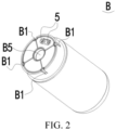
FIG. 2 is a schematic diagram of a power supply assembly according to an embodiment of this application; -
FIG. 3 is a cross-sectional view of an aerosol generation apparatus according to an embodiment of this application; -
FIG. 4 is another schematic exploded view of an aerosol generation apparatus according to an embodiment of this application; -
FIG. 5 is another schematic exploded view of an aerosol generation apparatus according to another embodiment of this application; and -
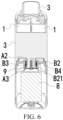
FIG. 6 is another cross-sectional view of an aerosol generation apparatus according to an embodiment of this application. - In the figures:
- A - cartridge assembly;
- 1 - cartridge; 11 - accommodating cavity; 12 - atomizer; 13 - first air passage;
- 2 - housing; 21 - bottom plate;
- 3 - nozzle member;
- 4 - first electrode group;
- 5 - second electrode group;
- 6 - elastic body: 61 - through hole; and 62 - annular convex rib; 7 - end cap;
- 8 - battery core;
- 9 - holding mechanism;
- A1 - first locking member; A2 - insertion member; A3 - stopper; and
- B - power supply assembly:
B 1 - second locking member; B2 - bracket; B21 - support plate; B3 - first limiting member; B4 - second limiting member; B5 - receiving hole; and B6 - anti-collision member. - The following clearly and completely describes the technical solutions in the embodiments of this application with reference to the accompanying drawings in the embodiments of this application. Apparently, the described embodiments are some rather than all of the embodiments of this application. All other embodiments obtained by a person of ordinary skill in the art based on the embodiments of this application without creative efforts shall fall within the protection scope of this application.
- The terms "first", "second", and "third" in this application are merely for the purpose of description, and shall not be construed as an indication or implication of relative importance or an implicit indication of a quantity or an order of indicated technical features. All directional indications (such as up, down, left, right, front, back...) in the embodiments of this application are only used to explain relative position relations, movement situation, or the like between components under a certain posture (as shown in the accompanying drawings). If the certain posture changes, the directional indication also changes accordingly. In addition, the terms "include", "have", and any variant thereof are intended to cover a non-exclusive inclusion. For example, a process, method, system, product, or device that includes a series of steps or units is not limited to the listed steps or units, but further optionally includes a step or unit that is not listed, or further optionally includes another step or unit that is intrinsic to the process, method, product, or device.
- "Embodiment" mentioned in the specification means that particular features, structures, or characteristics described with reference to the embodiment may be included in at least one embodiment of this application. The term appearing at different positions of the specification may not refer to the same embodiment or an independent or alternative embodiment that is mutually exclusive with another embodiment. A person skilled in the art explicitly or implicitly understands that the embodiments described in the specification may be combined with other embodiments.
- It is to be noted that, when a component is referred to as "being fixed to" another component, the component may be directly on the other component, or an intervening component may be present. When an element is considered to be "connected to" another element, the element may be directly connected to the another element, or one or more intervening elements may be also present. The terms "vertical", "horizontal", "left", "right" and similar expressions used in this specification are merely for purposes of illustration but not indicate a unique implementation.
- Refer to
FIG. 1 andFIG. 3 . An embodiment of this application provides an aerosol generation apparatus. The aerosol generation apparatus includes ahousing 2 and a cartridge assembly A including a plurality ofcartridges 1. Eachcartridge 1 may have anaccommodating cavity 11. Theaccommodating cavity 11 is configured to accommodate a liquid substrate that can be atomized to generate an aerosol. A volume of eachaccommodating cavity 11 is not greater than 5 ml. Eachcartridge 1 may further include an atomizer 12. The atomizer 12 is in fluid communication with theaccommodating cavity 11, and the atomizer 12 is configured to atomize the liquid substrate to generate an aerosol. - The plurality of
cartridges 1 may be held in thehousing 2 parallel to each other. The "plurality of" means two or more. In an embodiment shown inFIG. 3 , there are 4cartridges 1, but not limited thereto. At least twocartridges 1 in the plurality ofcartridges 1 may be configured to accommodate different liquid substrates, where the different liquid substrates include liquid substrates of different tastes or liquid substrates with different compositions and ratios. In this way, a user may be provided with aerosols having different sensory experience by operating atomizers indifferent cartridges 1 or simultaneously operating a plurality of atomizers 12, to provide the user with aerosols mixed in a predetermined ratio. Certainly, in an embodiment, liquid substrates accommodated in allcartridges 1 may be the same. - The liquid substrate may include a liquid including a tobacco-containing substance having a volatile tobacco-flavor component, and may further include a liquid including a non-tobacco substance. The liquid substrate may include water, a medicinal solution, a solvent, ethanol, a plant extract, a spice, a fragrance, a vitamin mixture, or the like. The spice may include an areca extract, menthol, peppermint, green mint oil, and various fruit flavor ingredients, but is not limited thereto. The fragrance may include ingredients that can provide various scents or flavors to the user. The vitamin mixture may be a mixture mixed with at least one of vitamin A, vitamin B, vitamin C, and vitamin E, but is not limited thereto. Based on different properties of the liquid substrate, the aerosol generation apparatus may be used in different fields, such as medical treatment, electronic aerosol atomization, and the like.
- The
housing 2 arranged around the plurality ofcartridges 1 may be at least partially transparent, so that thecartridges 1 in the housing can be visually observed through thehousing 2. A wall that is in thecartridge 1 and that is used for defining theaccommodating cavity 11 may also be at least partially transparent, so that an interior of thecartridge 1 may be visually observed respectively through thehousing 2 and the wall defining theaccommodating cavity 11, for example, a remaining amount of liquid substrates in thecartridge 1 is observed to provide the basis for the user to switch thecartridge 1. - The atomizer 12 may include a liquid absorbing element and a heating element. The liquid absorbing element may be a porous body or fibers, and can absorb a liquid substrate and guide the liquid substrate into an atomization range of the heating element. The heating element is configured to atomize at least some liquid substrates on the liquid absorbing element, to generate an aerosol. The heating element may be integrated on the liquid absorbing element, so that the heating element and the liquid absorbing element can be formed as a whole.
- Each of the
cartridges 1 may further include afirst air passage 13. Thefirst air passage 13 is in fluid communication with the atomizer 12, and thefirst air passage 13 is configured to deliver an aerosol. In an example, thecartridge 1 may have an atomization compartment in fluid communication with theaccommodating cavity 11, the atomizer 12 is accommodated in the atomization compartment, and afirst air passage 13 is in fluid communication with the atomization compartment. Alternatively, in another example, the atomizer 12 is at least partially arranged in thefirst air passage 13. - The aerosol generation apparatus may further include a
nozzle member 3. Thenozzle member 3 is in fluid communication with afirst air passage 13 of at least onecartridge 1, and thenozzle member 3 can be at least partially held in the mouth, so that the user may inhale an aerosol by inhaling thenozzle member 3. - Refer to
FIG. 1 andFIG. 2 . The aerosol generation apparatus further includes a power supply assembly B. The cartridge assembly A is rotatably connected to the power supply assembly B. In this way, based on relative rotation between the cartridge assembly A and the power supply assembly B, the power supply assembly B is enabled to provide power to atomizers indifferent cartridges 1 in the cartridge assembly A, to select an atomizer 12 in at least onecartridge 1 for operation, thereby providing an aerosol to the user. - Based on this, referring to
FIG. 1 , the cartridge assembly A further includes a plurality offirst electrode groups 4. A quantity offirst electrode groups 4 may be consistent with a quantity of atomizers 12. An atomizer 12 in eachcartridge 1 is exclusively electrically connected to one of thefirst electrode groups 4. In other words, one atomizer 12 is electrically connected to only onefirst electrode group 4, and onefirst electrode group 4 is electrically connected to only one atomizer 12, so that the plurality of atomizers 12 are electrically connected to differentfirst electrode groups 4 respectively. The atomizer 12 can draw power from thefirst electrode group 4 electrically connected to the atomizer, to atomize a liquid substrate in a corresponding accommodating cavity. Thefirst electrode group 4 may be a component in acorresponding cartridge 1. Thefirst electrode group 4 may be arranged at a far end (that is, on a bottom portion) of thecorresponding cartridge 1. - The power supply assembly B includes
second electrode groups 5. A quantity ofsecond electrode groups 5 is less than the quantity offirst electrode groups 4. When the cartridge assembly A rotates relative to the power supply assembly B, thefirst electrode group 4 rotates relative to thesecond electrode group 5, and at least onesecond electrode group 5 may be configured to electrically abut against differentfirst electrode groups 4 in turn when the cartridge assembly A rotates relative to the power supply assembly B. - In an embodiment, referring to
FIG. 2 , there is only onesecond electrode group 5. Thesecond electrode group 5 is configured to be electrically connected to thefirst electrode group 4 that rotates and abuts against the second electrode group, so that the power supply assembly B can only supply power to an atomizer 12 of one of thecartridges 1 at a same moment, so that only onecartridge 1 can generate an aerosol at the same moment. - Based on this, in an example, referring to
FIG. 4 andFIG. 6 , thenozzle member 3 may be simultaneously in fluid communication withfirst air passages 13 in the plurality ofcartridges 1, so that an aerosol generated by any cartridge can be delivered to thenozzle member 3 through afirst air passage 13 of thecartridge 1. Alternatively, in an example, referring toFIG. 5 , thenozzle member 3 is configured to be rotatable relative to the cartridge assembly A, so that based on relative rotation between thenozzle member 3 and the cartridge assembly A, thenozzle member 3 is enabled to be in fluid communication with afirst air passage 13 of one of thecartridges 1 at a same moment. In addition, afirst electrode group 4 corresponding to thecartridge 1 in fluid communication with thenozzle member 3 is electrically connected to thesecond electrode group 5 at the same moment. In this way, acartridge 1 only electrically connected to thesecond electrode group 5 at the same moment can generate an aerosol, and afirst air passage 13 of thecartridge 1 can be in fluid communication with thenozzle member 3. - In an embodiment shown in
FIG. 5 , the aerosol generation apparatus further includes anelastic body 6 and anend cap 7. Theend cap 7 is connected to a near end of thehousing 2, thenozzle member 3 is rotatably connected to theend cap 7, and thenozzle member 3 rotates relative to theend cap 7 to rotate relative to the cartridge assembly A. Theend cap 7 has a plurality ofsecond air passages 71. Eachsecond air passage 7 is exclusively in fluid communication with onefirst air passage 13, theelastic body 6 is at least partially arranged between theend cap 7 and anozzle member 3, and theelastic body 6 may be configured to provide resistance on rotation between thenozzle member 3 andend cap 7, to prevent thenozzle member 3 from rotating relative to theend cap 7 when rotation relative to theend cap 7 is not necessary. Theend cap 7 may have a groove. Theelastic body 6 may be at least partially accommodated in the groove, and a throughhole 61 for asecond channel 71 to pass through is provided on theelastic body 6. Theelastic body 6 may be fitted with theend cap 7 through the throughhole 61, to be unable to rotate relative to theend cap 7. Theelastic body 6 may have an annularconvex rib 62 surrounding the throughhole 61. The annularconvex rib 62 elastically abuts against thenozzle member 3, the annularconvex rib 62 is configured to air-tightly isolate asecond channel 71 and the throughhole 61 surrounded by the through hole from another throughhole 61 andsecond channel 71. In addition, the annularconvex rib 62 rubs thenozzle member 3 when thenozzle member 3 rotates relative to theend cap 7, to prevent thenozzle member 3 from rotating relative to theend cap 7. - It is to be noted that, in other examples, there may be a plurality of second electrode groups, and the nozzle member may also be simultaneously in fluid communication with first air passages in the plurality of cartridges, so that the power supply assembly may simultaneously supply power to atomizers in the plurality of cartridges, and the user can simultaneously inhale, through the nozzle member, aerosols generated by the plurality of cartridges. For example, when there are two second electrode groups, the two second electrode groups may respectively electrically abut against two first electrode groups, so that the power supply assembly simultaneously supplies power to atomizers in two cartridges. In this example, the nozzle member can be simultaneously in fluid communication with first air passages of the two cartridges, so that the user can simultaneously inhale, through the nozzle member, aerosols generated by the two cartridges.
- The
first electrode group 4 and thesecond electrode group 5 may each include at least two electrodes, where the electrodes may be, for example, an anode electrode and a cathode electrode respectively. - The power supply assembly B may include any
suitable battery core 8. In an embodiment, thebattery core 8 is a lithium ion battery. Alternatively, thebattery core 8 may be a nickel metal hydride battery, a nickel-cadmium battery, or a lithium-based battery, for example, a lithium cobalt battery, a lithium iron phosphate lithium cobalt battery, a lithium titanate lithium cobalt battery, or a lithium polymer battery. The power supply assembly B may include a circuit board and one or more control circuits arranged on the circuit board. The control circuit may control output of thebattery core 8, for example, enabling thebattery core 8 to output an alternating current or a direct current, or for example, enabling thebattery core 8 to output current or voltage in a form of pulses. - The control circuit may have one or more controllers thereon. The controller may control overall operations by the aerosol generation apparatus. To be specific, the controller not only controls operations by the battery core and the cartridge, but also controls an operation by another element in the aerosol generation apparatus. In addition, the controller may determine whether the aerosol generation apparatus is operable by checking a status of an element of the aerosol generation apparatus.
- The aerosol generation apparatus may further include a control switch. After at least one second electrode group electrically abuts against at least one first electrode group, the power supply assembly may be controlled, through the control switch, to provide voltage, current, or electric power to a corresponding first electrode group through the second electrode group.
- There is an interlocking mechanism between the cartridge assembly A and the power supply assembly B. The interlocking mechanism is configured to prevent the cartridge assembly A from rotating relative to the power supply assembly B. The interlocking mechanism may ensure that a selected
cartridge 1 maintains a stable electrical connection to the power supply assembly B, to avoid a sudden open circuit between thecorresponding cartridge 1 and the power supply assembly B during use of the aerosol generation apparatus. In addition, the interlocking mechanism may prevent the aerosol generation apparatus from being used by inappropriate people, such as children or elderly people. - The interlocking mechanism may include a first locking member A1 arranged on the cartridge assembly A and a second
locking member B 1 arranged on the power supply assembly B. In an embodiment, the first locking member A1 and the second locking member B1 are magnetically attractable to each other, to prevent, based on magnetic attraction, the cartridge assembly A from rotating relative to the power supply assembly B. In an embodiment, when the first locking member A1 and the secondlocking member B 1 are fitted with each other, for example, when at least one of the first locking member A1 and the secondlocking member B 1 at least partially enters the other one, the interlocking mechanism is locked, so that the cartridge assembly A cannot rotate relative to the power supply assembly B. When the first locking member A1 and the secondlocking member B 1 are separated from each other, the interlocking mechanism is unlocked, so that the cartridge assembly A can rotate relative to the power supply assembly B, to further select and switch afirst electrode group 4 that electrically abuts against the power supply assembly B. - When the interlocking mechanism is locked by fitting the first locking member A1 with the second
locking member B 1, in an embodiment, referring toFIG. 1 , the first locking member A1 is configured to be slidable relative to the secondlocking member B 1, and a direction in which the first locking member A1 slides relative to the secondlocking member B 1 is perpendicular to a direction in which the cartridge assembly A rotates relative to the power supply assembly B, or a direction in which the first locking member A1 slides relative to the secondlocking member B 1 is substantially parallel to an axis in which the cartridge assembly A rotates relative to the power supply assembly B. - Based on this, in an example, when the first locking member slides relative to the second locking member, the first locking member can also slide relative to other parts of the cartridge assembly, such as the cartridge, the first electrode group, or the housing, so that when the first locking member slides relative to the second locking member, the other parts of the cartridge assembly may remain static relative to the power supply assembly. Alternatively, when the first locking member slides relative to the second locking member, the second electrode group may maintain an electrical connection with a selected first electrode group until the interlocking mechanism is unlocked and the cartridge assembly rotates relative to the power supply assembly by an angle, and the second electrode group may disconnect the electrical connection with the selected first electrode assembly. In an example, when the second locking member slides relative to the first locking member, the second locking member can also slide relative to other parts of the power supply assembly, such as the battery core or the second electrode group, so that when the first locking member slides relative to the second locking member, the other parts of the power supply assembly may remain static relative to the cartridge assembly. Alternatively, when the first locking member slides relative to the second locking member, the second electrode group may maintain an electrical connection with a selected first electrode assembly.
- Alternatively, in another example, referring to
FIG. 1 andFIG. 2 , when the first locking member A1 slides relative to the secondlocking member B 1, the cartridge assembly A slides relative to the power supply assembly B, and the direction in which the first locking member A1 slides relative to the second locking member B1 is perpendicular to the direction in which the cartridge assembly A rotates relative to the power supply assembly B, or the direction in which the first locking member A1 slides relative to the secondlocking member B 1 is substantially parallel to the axis in which the cartridge assembly A rotates relative to the power supply assembly B. - The interlocking mechanism may be unlocked when the cartridge assembly A slides along the power supply assembly B to a third position. In other words, when the cartridge assembly A slides along the power supply assembly B to the third position, the first locking member A1 and the second
locking member B 1 are separated from each other, so that the cartridge assembly A may rotate relative to the power supply assembly B. - Referring to
FIG. 3 , the power supply assembly B includes a bracket B2. The second electrode group5 may be fixed to the bracket B2, a docking cavity is defined between the cartridge assembly A and a far end of thehousing 2, and thefirst electrode group 4 is at least partially exposed in the docking cavity, so that when the bracket B2 is at least partially inserted into the docking cavity, at least onefirst electrode group 4 can abut against thesecond electrode group 5. A near end that is of thehousing 2 and that is opposite to the far end is connected to thenozzle member 3 or close to thenozzle member 3. - A slider is arranged on one of the far end of the
housing 2 and the bracket B2, and a sliding groove is provided on the other one. The slider is slidably connected to the sliding groove, that is, one of the first locking member A1 and the secondlocking member B 1 may be a slider, and the other one may be a sliding groove. The interlocking mechanism is locked when the slider is connected to the sliding groove, and the interlocking mechanism is unlocked when the slider is disengaged from the sliding groove. More specifically, the slider and the sliding groove are separated from each other when the cartridge assembly A slides along the power supply assembly B to the third position. - The cartridge assembly A is configured to be slidable along the power supply assembly B between the first position and the second position, that is, the cartridge assembly A may remain connected to the power supply assembly B between the first position and the second position. The
second electrode group 5 electrically abuts against the selectedfirst electrode group 4 when the cartridge assembly A is at the first position. - To prevent the cartridge assembly A from continuing to slide in an original sliding direction after sliding along the power supply assembly B to the second position. Referring to
FIG. 6 , the power supply assembly B may include a first limiting member B3. The first limiting member B3 is configured to abut against the cartridge assembly A when the cartridge assembly A slides along the power supply assembly B to the second position, to prevent the cartridge assembly A from being separated from the power supply assembly B. - Referring to
FIG. 6 , the power supply assembly B may include a second limiting member B4. The second limiting member B4 is configured to support the cartridge assembly A when the cartridge assembly A slides along the power supply assembly B to the first position, to prevent the cartridge assembly A from continuing to slide in the original sliding direction after sliding along the power supply assembly B to the first position, thereby preventing thesecond electrode group 5 from excessively squeezing the selectedfirst electrode group 4. - The third position may be located between the first position and the second position. In other words, after the cartridge assembly A slides along the power supply assembly B from the first position to the third position to enable the interlocking mechanism to be unlocked, the cartridge assembly A may further be enabled to continue to slide in the original sliding direction until sliding to the second position. Certainly, in some embodiments, the third position is the second position, that is, the third position overlaps the second position.
- On the basis that the interlocking mechanism is unlocked when the cartridge assembly A slides along the power supply assembly B to the third position, referring to
FIG. 6 , the aerosol generation apparatus may further include a holding mechanism 9. The holding mechanism 9 is connected to the cartridge assembly A and the power supply assembly B. The holding mechanism 9 is configured to provide resistance for the cartridge assembly A to slide from the first position to the second position. In other words, the holding mechanism 9 helps to hold the cartridge assembly A at the first position, or helps the cartridge assembly A at the third position or the second position return to the first position. The holding mechanism 9 may ensure that the interlocking mechanism can remain locked, to prevent the interlocking mechanism from being unlocked when not necessary, and may ensure that thesecond electrode group 5 of the power supply assembly B can remain a stable electrical connection to the selectedfirst electrode group 4. - More specifically, in an example, referring to
FIG. 1 ,FIG. 2 , andFIG. 6 , a receiving mechanism is arranged at a center of a cross section of one of the cartridge assembly A and the power supply assembly B, and an insertion mechanism is arranged at a center of a cross section of the other, the insertion mechanism is at least partially arranged in a receiving hole B5 of the receiving mechanism in a rotatable manner, the insertion mechanism is configured to be movable along a central axis of the receiving hole B5, and a direction in which the insertion mechanism moves along the central axis is consistent with the direction in which the cartridge assembly A slides relative to the power supply assembly B. The holding mechanism 9 is connected to the insertion mechanism and the receiving mechanism B5. - The receiving mechanism has a holding cavity. The insertion mechanism includes an insertion member A2 and a stopper A3 connected to the insertion member A2. At least a part of the insertion member A2 is located in the receiving hole B5 and is rotatable in the receiving hole B5. The stopper A3 supports the holding mechanism 9, to hold the holding mechanism 9 in the holding cavity, and the stopper A3 is configured to be rotatable relative to the holding mechanism 9. The stopper A3 may be located in the holding cavity, and when the cartridge assembly A slides along the power supply assembly B and between the first position and the second position, the stopper A3 may be located in the holding cavity and move up and down in the holding cavity. An outer diameter of the stopper A3 (that is, a maximum distance between an outer contour and a central axis of the stopper) may be greater than an aperture of at least a part of the receiving hole B5, to prevent the insertion mechanism from disengaging from the receiving hole B5. The stopper A3 may abut against the first limiting member B3 when the cartridge assembly A slides along the power supply assembly B to the second position, to prevent the cartridge assembly A from being separated from the power supply assembly B.
- More specifically, the cartridge assembly A includes the insertion mechanism, and the power supply assembly B includes the receiving mechanism.
- The
housing 2 of the cartridge assembly A has a bottom plate 21. The bottom plate 21 is configured to support a plurality ofcartridges 1, to hold the plurality ofcartridges 1 in thehousing 2. The bottom plate 21 has a plurality of mounting holes, each mounting hole is embedded by a far end of at least onecartridge 1, and thefirst electrode group 4 may be exposed through a corresponding mounting hole. The insertion mechanism is connected to the bottom plate 21, the insertion mechanism is at least partially located in the docking cavity, and the insertion mechanism may be located at a center of a cross section of the bottom plate 21. Thehousing 2, the bottom plate 21, and the insertion member A2 of the insertion mechanism may be integrally formed through injection molding. - The receiving mechanism may be formed on a part of the bracket B2. The bracket B2 includes a support plate B21. At least a part of the support plate B21 defines a boundary of a near end of the holding cavity. The receiving hole B5 penetrates the support plate B21 and is located at a center of the bracket B2. The
second electrode group 5 is fixed to the support plate B21. - The holding mechanism 9 may be an elastic member, for example, a spiral spring. The elastic member may surround a periphery of the insertion member A2. A near end and a far end of the elastic member may respectively abut against the support plate B21 and a stopper A3. When the cartridge assembly A is at the first position, the elastic member is in an elastic compression state and has first elastic potential energy. When the cartridge assembly A is at the second position, the elastic member is in an elastic compression state and has second elastic potential energy. An elastic force provided by the first elastic potential energy is used for holding the cartridge assembly A at the first position and preventing the cartridge assembly A from sliding to the second position. The second elastic potential energy is greater than the first elastic potential energy.
- Alternatively, the holding mechanism may be a magnetic assembly. For example, the holding mechanism includes a first magnetic member and a second magnetic member. The first magnetic member is arranged on the support plate, the second magnetic member is arranged on the stopper. The first magnetic member and the second magnetic member repel each other, and a repulsive force between the first magnetic member and the second magnetic member when the cartridge assembly is at the first position is less than a repulsive force when the cartridge assembly is at the second position.
- In an embodiment, referring to
FIG. 2 andFIG. 6 , the aerosol generation apparatus may further include an anti-collision member B6. The anti-collision member B6 is configured to elastically abut against the cartridge assembly A and/or the power supply assembly B when the cartridge assembly A is at the first position. Specifically, the anti-collision member B6 may be arranged between the bottom plate 21 of the cartridge assembly A and the support plate B21 of the power supply assembly B. The anti-collision member B6 may have a through hole, and the second electrode group5 may penetrate the through hole. More specifically, the anti-collision member B6 may be fixed to the bracket B2. - It is to be noted that, this specification of this application and the accompanying drawings thereof illustrate preferred embodiments of this application, but this application is not limited to the embodiments described in this specification. Further, a person of ordinary skill in the art may make improvements or modifications according to the foregoing description, and all the improvements and modifications shall fall within the protection scope of the attached claims of this application.
Claims (14)
- An aerosol generation apparatus, comprising:a cartridge assembly (A), comprising a plurality of cartridges (1), each of the cartridges (1) having an accommodating cavity (11) for accommodating a liquid substrate, an atomizer (12) for atomizing the liquid substrate, and a first electrode group (4) electrically connected to the atomizer (12); anda power supply assembly (B), rotatably connected to the cartridge assembly (A), the power supply assembly (B) comprising a second electrode group (5), the second electrode group (5) being configured to be electrically connected to the first electrode group (4) in any of the cartridges (1) during rotation, whereinthere is an interlocking mechanism between the cartridge assembly (A) and the power supply assembly (B), and the interlocking mechanism is configured to prevent the cartridge assembly (A) from rotating relative to the power supply assembly (B).
- The aerosol generation apparatus according to claim 1, wherein the interlocking mechanism comprises a first locking member (A1) arranged on the cartridge assembly (A) and a second locking member (B 1) arranged on the power supply assembly (B), and the first locking member (A1) is capable of being fitted with the second locking member (B1) to prevent the cartridge assembly (A) and the power supply assembly (B) from rotating relative to each other.
- The aerosol generation apparatus according to claim 2, wherein the first locking member (A1) is configured to be slidable relative to the second locking member (B1), and a direction in which the first locking member (A1) slides relative to the second locking member (B 1) is substantially parallel to an axis in which the cartridge assembly (A) rotates relative to the power supply assembly (B).
- The aerosol generation apparatus according to claim 1, wherein the cartridge assembly (A) is configured to be slidable relative to the power supply assembly (B), and a direction in which the cartridge assembly (A) slides relative to the power supply assembly (B) is substantially parallel to an axis in which the cartridge assembly (A) rotates relative to the power supply assembly (B).
- The aerosol generation apparatus according to claim 4, wherein the power supply assembly (B) comprises a first limiting member (B3) and a second limiting member (B4), and a slide stroke of the cartridge assembly (A) is provided between the first limiting member (B3) and the second limiting member (B4).
- The aerosol generation apparatus according to claim 4, wherein the cartridge assembly (A) slides relative to the power supply assembly (B) and between a first position and a second position, the interlocking mechanism is locked when the cartridge assembly (A) is at the first position, and the interlocking mechanism is unlocked when the cartridge assembly (A) is at the second position.
- The aerosol generation apparatus according to claim 4, wherein the aerosol generation apparatus further comprises a holding mechanism (9), the holding mechanism (9) is connected to the cartridge assembly (A) and the power supply assembly (B), the cartridge assembly (A) is configured to be slidable along the power supply assembly (B) and between the first position and the second position, and the holding mechanism (9) is configured to provide resistance for the cartridge assembly (A) to slide from the first position to the second position.
- The aerosol generation apparatus according to claim 7, wherein the holding mechanism (9) comprises an elastic member or a magnetic assembly.
- The aerosol generation apparatus according to claim 7, wherein a receiving mechanism (B5) is arranged at a center of a cross section of one of the cartridge assembly(A) and the power supply assembly (B), an insertion mechanism is arranged at a center of a cross section of the other one, the insertion mechanism is at least partially arranged in a receiving hole (B5) of the receiving mechanism (B5) in a rotatable manner, the insertion mechanism is configured to be movable along a central axis of the receiving hole (B5), and a direction in which the insertion mechanism moves along the central axis is consistent with the direction in which the cartridge assembly(A) slides relative to the power supply assembly (B); and
the holding mechanism (9) is connected to the insertion mechanism and the receiving mechanism (B5). - The aerosol generation apparatus according to claim 9, wherein the receiving mechanism (B5) has a holding cavity, a stopper (A3) is arranged on the insertion mechanism, the stopper (A3) supports the holding mechanism (9) to hold the holding mechanism (9) in the holding cavity, and the stopper (A3) is configured to be rotatable relative to the holding mechanism (9).
- The aerosol generation apparatus according to claim 9, wherein a stopper (A3) is arranged on the insertion mechanism, and an outer diameter of the stopper (A3) is greater than an aperture of at least a part of the receiving hole (B5), to prevent the insertion mechanism from disengaging from the receiving hole (B5).
- The aerosol generation apparatus according to claim 7, wherein the aerosol generation apparatus further comprises an anti-collision member (B6), and the anti-collision member (B6) is configured to elastically abut against the cartridge assembly (A) and/or the power supply assembly (B) when the cartridge assembly (A) is at the first position.
- The aerosol generation apparatus according to claim 1, wherein each of the cartridges has a first air passage (13) in fluid communication with the atomizer (12); and
the aerosol generation apparatus further comprises a nozzle member (3), and the nozzle member (3) is configured to be rotatably connected to the cartridge assembly (A), so that the nozzle member (3) rotates relative to the cartridge assembly (A) to be in fluid communication with a first air passage (13) in one of the cartridges (1). - The aerosol generation apparatus according to claim 1, wherein each of the cartridges (1) has a first air passage (13) in fluid communication with the atomizer (12); and
the aerosol generation apparatus further comprises a nozzle member (3), and the nozzle member (3) is simultaneously in fluid communication with first air passage (13) in the cartridges (1).
Applications Claiming Priority (1)
| Application Number | Priority Date | Filing Date | Title |
|---|---|---|---|
| CN202321156631.3U CN220274894U (en) | 2023-05-12 | 2023-05-12 | aerosol generating device |
Publications (2)
| Publication Number | Publication Date |
|---|---|
| EP4461148A1 true EP4461148A1 (en) | 2024-11-13 |
| EP4461148B1 EP4461148B1 (en) | 2026-05-06 |
Family
ID=89326372
Family Applications (1)
| Application Number | Title | Priority Date | Filing Date |
|---|---|---|---|
| EP24164228.9A Active EP4461148B1 (en) | 2023-05-12 | 2024-03-18 | Aerosol generation apparatus |
Country Status (3)
| Country | Link |
|---|---|
| EP (1) | EP4461148B1 (en) |
| CN (1) | CN220274894U (en) |
| GB (1) | GB2626459A (en) |
Families Citing this family (7)
| Publication number | Priority date | Publication date | Assignee | Title |
|---|---|---|---|---|
| CN221769341U (en) * | 2024-02-02 | 2024-09-27 | 深圳市合元科技有限公司 | Aerosol Generating Devices and Nebulizers |
| GB2639056A (en) * | 2024-03-08 | 2025-09-10 | Pax Innovations Shenzhen Ltd | Electronic cigarette |
| US12137736B1 (en) * | 2024-03-08 | 2024-11-12 | PAX Innovations (Shenzhen) Limited | Electronic cigarette having a plurality of e-liquid storage bins |
| CN121003330A (en) * | 2024-05-24 | 2025-11-25 | 思摩尔国际控股有限公司 | Information processing method and electronic device for e-cigarette cartridges based on electronic atomizers |
| CN121003331A (en) * | 2024-05-24 | 2025-11-25 | 思摩尔国际控股有限公司 | Information processing method and electronic device for e-cigarette cartridges based on electronic atomizers |
| CN121080673A (en) * | 2024-06-06 | 2025-12-09 | 思摩尔国际控股有限公司 | Atomizing device and aerosol generating device |
| CN121176670A (en) * | 2024-06-21 | 2025-12-23 | 深圳市合元科技有限公司 | aerosol generating device |
Citations (2)
| Publication number | Priority date | Publication date | Assignee | Title |
|---|---|---|---|---|
| US20160366940A1 (en) * | 2014-02-28 | 2016-12-22 | Kimree Hi-Tech Inc. | Electronic cigarette and electronic cigarette atomization control method |
| US20200093184A1 (en) * | 2018-09-25 | 2020-03-26 | Gyre Vapes Llc | Handheld vaporizing device with rotating liquid housing chamber |
Family Cites Families (3)
| Publication number | Priority date | Publication date | Assignee | Title |
|---|---|---|---|---|
| CN203873003U (en) * | 2014-04-16 | 2014-10-15 | 林光榕 | Electronic cigarette |
| CN220109154U (en) * | 2023-05-12 | 2023-12-01 | 深圳市合元科技有限公司 | Aerosol generating device |
| CN220712903U (en) * | 2023-08-09 | 2024-04-05 | 深圳市合元科技有限公司 | Aerosol generating device |
-
2023
- 2023-05-12 CN CN202321156631.3U patent/CN220274894U/en active Active
-
2024
- 2024-03-18 GB GB2403845.7A patent/GB2626459A/en active Pending
- 2024-03-18 EP EP24164228.9A patent/EP4461148B1/en active Active
Patent Citations (2)
| Publication number | Priority date | Publication date | Assignee | Title |
|---|---|---|---|---|
| US20160366940A1 (en) * | 2014-02-28 | 2016-12-22 | Kimree Hi-Tech Inc. | Electronic cigarette and electronic cigarette atomization control method |
| US20200093184A1 (en) * | 2018-09-25 | 2020-03-26 | Gyre Vapes Llc | Handheld vaporizing device with rotating liquid housing chamber |
Also Published As
| Publication number | Publication date |
|---|---|
| EP4461148B1 (en) | 2026-05-06 |
| CN220274894U (en) | 2024-01-02 |
| GB2626459A (en) | 2024-07-24 |
| GB202403845D0 (en) | 2024-05-01 |
Similar Documents
| Publication | Publication Date | Title |
|---|---|---|
| EP4461148B1 (en) | Aerosol generation apparatus | |
| EP4461147B1 (en) | Aerosol generation device | |
| US11241043B2 (en) | Vapor provision apparatus | |
| JP4369062B2 (en) | Aerosol delivery device for lung disease | |
| EP4527218A2 (en) | Aerosol generation device | |
| JP7430178B2 (en) | Electrospinning device, electrospinning system, and electrospinning method | |
| EP3962303B1 (en) | Aerosol generating device | |
| CN218457270U (en) | Position adjusting assembly and atomizing device capable of switching flavors | |
| CN222109279U (en) | Aerosol generating device | |
| CN217826790U (en) | Press rotary type aerial fog generating device | |
| CN222656332U (en) | Atomizer and electronic atomization device | |
| CN221670983U (en) | Aerosol generating device | |
| WO2025161930A1 (en) | Aerosol generation apparatus and atomizer | |
| CN220875920U (en) | Aerosol generating device | |
| CN220423122U (en) | Atomizer and electronic atomization device | |
| US20250187024A1 (en) | Electrostatic spraying device and cartridge for electrostatic spraying device | |
| CN223968627U (en) | Atomizer and aerosol-generating device | |
| CN223968626U (en) | Aerosol matrix storage assembly and aerosol generating device comprising same | |
| CN120419709A (en) | Aerosol generating device | |
| CN223873287U (en) | Atomizer and aerosol-generating device | |
| CN221284669U (en) | Aerosol generating device | |
| CN223515763U (en) | Electronic atomizing device | |
| EP4516142A2 (en) | Aerosol generation apparatus | |
| EP4570087A1 (en) | Vapor generation apparatus | |
| US12329209B1 (en) | Electronic atomizer capable of automatically emitting vapor |
Legal Events
| Date | Code | Title | Description |
|---|---|---|---|
| PUAI | Public reference made under article 153(3) epc to a published international application that has entered the european phase |
Free format text: ORIGINAL CODE: 0009012 |
|
| STAA | Information on the status of an ep patent application or granted ep patent |
Free format text: STATUS: REQUEST FOR EXAMINATION WAS MADE |
|
| 17P | Request for examination filed |
Effective date: 20240318 |
|
| AK | Designated contracting states |
Kind code of ref document: A1 Designated state(s): AL AT BE BG CH CY CZ DE DK EE ES FI FR GB GR HR HU IE IS IT LI LT LU LV MC ME MK MT NL NO PL PT RO RS SE SI SK SM TR |
|
| STAA | Information on the status of an ep patent application or granted ep patent |
Free format text: STATUS: EXAMINATION IS IN PROGRESS |
|
| 17Q | First examination report despatched |
Effective date: 20250612 |
|
| GRAP | Despatch of communication of intention to grant a patent |
Free format text: ORIGINAL CODE: EPIDOSNIGR1 |
|
| STAA | Information on the status of an ep patent application or granted ep patent |
Free format text: STATUS: GRANT OF PATENT IS INTENDED |
|
| RIC1 | Information provided on ipc code assigned before grant |
Ipc: A24F 40/30 20200101AFI20260121BHEP Ipc: A24F 40/40 20200101ALI20260121BHEP Ipc: A24F 40/42 20200101ALN20260121BHEP Ipc: A24F 40/10 20200101ALN20260121BHEP |
|
| INTG | Intention to grant announced |
Effective date: 20260205 |
|
| GRAS | Grant fee paid |
Free format text: ORIGINAL CODE: EPIDOSNIGR3 |
|
| GRAA | (expected) grant |
Free format text: ORIGINAL CODE: 0009210 |
|
| STAA | Information on the status of an ep patent application or granted ep patent |
Free format text: STATUS: THE PATENT HAS BEEN GRANTED |
|
| AK | Designated contracting states |
Kind code of ref document: B1 Designated state(s): AL AT BE BG CH CY CZ DE DK EE ES FI FR GB GR HR HU IE IS IT LI LT LU LV MC ME MK MT NL NO PL PT RO RS SE SI SK SM TR |
|
| REG | Reference to a national code |
Ref country code: CH Ref legal event code: F10 Free format text: ST27 STATUS EVENT CODE: U-0-0-F10-F00 (AS PROVIDED BY THE NATIONAL OFFICE) Effective date: 20260506 Ref country code: GB Ref legal event code: FG4D |