EP4461147A1 - Aerosol generation device - Google Patents
Aerosol generation device Download PDFInfo
- Publication number
- EP4461147A1 EP4461147A1 EP24164472.3A EP24164472A EP4461147A1 EP 4461147 A1 EP4461147 A1 EP 4461147A1 EP 24164472 A EP24164472 A EP 24164472A EP 4461147 A1 EP4461147 A1 EP 4461147A1
- Authority
- EP
- European Patent Office
- Prior art keywords
- mouthpiece
- generation device
- cartridge
- rotating portion
- aerosol generation
- Prior art date
- Legal status (The legal status is an assumption and is not a legal conclusion. Google has not performed a legal analysis and makes no representation as to the accuracy of the status listed.)
- Granted
Links
Images


Classifications
-
- A—HUMAN NECESSITIES
- A24—TOBACCO; CIGARS; CIGARETTES; SIMULATED SMOKING DEVICES; SMOKERS' REQUISITES
- A24F—SMOKERS' REQUISITES; MATCH BOXES; SIMULATED SMOKING DEVICES
- A24F40/00—Electrically operated smoking devices; Component parts thereof; Manufacture thereof; Maintenance or testing thereof; Charging means specially adapted therefor
- A24F40/30—Devices using two or more structurally separated inhalable precursors, e.g. using two liquid precursors in two cartridges
-
- A—HUMAN NECESSITIES
- A24—TOBACCO; CIGARS; CIGARETTES; SIMULATED SMOKING DEVICES; SMOKERS' REQUISITES
- A24F—SMOKERS' REQUISITES; MATCH BOXES; SIMULATED SMOKING DEVICES
- A24F40/00—Electrically operated smoking devices; Component parts thereof; Manufacture thereof; Maintenance or testing thereof; Charging means specially adapted therefor
- A24F40/40—Constructional details, e.g. connection of cartridges and battery parts
-
- A—HUMAN NECESSITIES
- A24—TOBACCO; CIGARS; CIGARETTES; SIMULATED SMOKING DEVICES; SMOKERS' REQUISITES
- A24F—SMOKERS' REQUISITES; MATCH BOXES; SIMULATED SMOKING DEVICES
- A24F40/00—Electrically operated smoking devices; Component parts thereof; Manufacture thereof; Maintenance or testing thereof; Charging means specially adapted therefor
- A24F40/40—Constructional details, e.g. connection of cartridges and battery parts
- A24F40/48—Fluid transfer means, e.g. pumps
- A24F40/485—Valves; Apertures
-
- A—HUMAN NECESSITIES
- A24—TOBACCO; CIGARS; CIGARETTES; SIMULATED SMOKING DEVICES; SMOKERS' REQUISITES
- A24F—SMOKERS' REQUISITES; MATCH BOXES; SIMULATED SMOKING DEVICES
- A24F40/00—Electrically operated smoking devices; Component parts thereof; Manufacture thereof; Maintenance or testing thereof; Charging means specially adapted therefor
- A24F40/60—Devices with integrated user interfaces
-
- A—HUMAN NECESSITIES
- A24—TOBACCO; CIGARS; CIGARETTES; SIMULATED SMOKING DEVICES; SMOKERS' REQUISITES
- A24F—SMOKERS' REQUISITES; MATCH BOXES; SIMULATED SMOKING DEVICES
- A24F40/00—Electrically operated smoking devices; Component parts thereof; Manufacture thereof; Maintenance or testing thereof; Charging means specially adapted therefor
- A24F40/10—Devices using liquid inhalable precursors
Definitions
- Embodiments of this application relate to the field of aerosol generation technologies, and in particular, to an aerosol generation device.
- An aerosol generation device is a device that can atomize liquid preparations to form aerosol.
- the aerosol generation device often has only one cartridge for storing the liquid preparations. Due to a limitation of a volume of a single cartridge, a capacity and a type of a liquid substrate stored in the aerosol generation device are limited, affecting user experience.
- This application aims to provide an aerosol generation device, to have a large liquid substrate storage capacity.
- an elastic member is fixed on at least one of the mouthpiece and the end cap, and the elastic member is configured to provide resistance to rotation of the mouthpiece relative to the end cap.
- the elastic member is arranged around the second rotating portion.
- At least part of the elastic member is longitudinally squeezed by the mouthpiece and the end cap.
- the elastic member is provided with a through hole
- the end cap is provided with a convex column
- at least part of the convex column is embedded into the through hole, to fix the elastic member.
- the elastic member is provided with a plurality of annular ribs, each annular rib surrounds one through hole, and the annular rib elastically abuts against the mouthpiece.
- the end cap is provided with a support platform, and the support platform always abuts against the mouthpiece, and is slidably connected to the mouthpiece when the mouthpiece rotates relative to the end cap.
- a side of the end cap toward the mouthpiece is provided with a groove recessed relative to the support platform, and at least part of the elastic member is accommodated in the groove.
- a prompting mechanism is arranged on the aerosol generation device, and the prompting mechanism is configured to provide tactile feedback when the mouthpiece rotates to a position at which the mouthpiece is in airflow communication with one second channel.
- the end cap is provided with a support platform and a plurality of second airways
- one of the support platform and the mouthpiece is provided with bumps in a one-to-one correspondence with the plurality of second airways
- the other one is provided with at least one pit
- at least one bump is embedded into one pit, to generate tactile feedback.
- the first rotating portion includes a rotating hole
- the second rotating portion includes an elastic piece and a claw connected to the elastic piece, at least part of the elastic piece is located in the rotating hole, an outer diameter of the claw is greater than a hole diameter of at least part of the rotating hole, and the claw is configured to grip the first rotating portion.
- each cartridge includes an atomizer in fluid communication with the accommodation cavity in the cartridge, the atomizer is configured to atomize the liquid substrate to generate aerosol, and the first airway in the cartridge is in fluid communication with the atomizer corresponding to the cartridge to transmit the aerosol.
- the aerosol generation device further includes a power supply assembly, a second electrode set is arranged on the power supply assembly, the cartridge assembly includes a plurality of first electrode sets, and the atomizer of each cartridge is electrically connected to different first electrode sets; and the cartridge assembly is rotatably connected to the power supply assembly, and the second electrode set is configured to be in electrical communication with a first electrode set that is rotated to and that abuts against the second electrode set.
- the aerosol generation device further includes a power supply assembly and a control switch electrically connected to the power supply assembly, and the control switch is configured to control the power supply assembly to be in electrical communication with an atomizer of one cartridge.
- the aerosol generation device further includes a plurality of airflow channels in a one-to-one correspondence with the plurality of cartridges, each airflow channel is in fluid communication with a first channel of a corresponding cartridge, the control switch is arranged in each airflow channel, and the control switch is configured to control, based on an airflow speed or an atmospheric pressure in the airflow channel, the cartridge corresponding to the airflow channel to be in electrical communication with the power supply assembly.
- the aerosol generation device further includes a power supply assembly, the power supply assembly includes a plurality of battery cores, and the plurality of battery cores are electrically connected to atomizers of different cartridges respectively and correspondingly.
- the aerosol generation device includes a cartridge assembly including a plurality of cartridges, each cartridge is provided with an accommodation cavity for accommodating a liquid substrate and a first airway for airflow to pass through, and a suction nozzle is rotatably connected to an end cap connected to the cartridge assembly, so that the suction nozzle can be in fluid communication with one second channel on the end cap by making the suction nozzle and the cartridge assembly relatively rotate, to cause the suction nozzle to be in fluid communication with a first channel of one cartridge. Therefore, the cartridge in communication with the suction nozzle can be selected by making the suction nozzle and the cartridge assembly relatively rotate, to break through a volume limitation of a single cartridge, and there is no need to disassemble the cartridge to switch to different cartridges. This improves user experience and facilitates use of users while helping to increase a storage capacity of the liquid substrate.
- a process, method, system, product, or device that includes a series of steps or units is not limited to the listed steps or units; and instead, further optionally includes a step or unit that is not listed, or further optionally includes another step or unit that is intrinsic to the process, method, product, or device.
- the aerosol generation device includes a mouthpiece 1 and a cartridge assembly A including a plurality of cartridges 2.
- Each cartridge 2 may be provided with an accommodation cavity 21, the accommodation cavity 21 is for accommodating a liquid substrate that can be atomized to generate aerosol, and a volume of the accommodation cavity 21 may not exceed 5 ml.
- Each cartridge 2 is provided with a first airway 22.
- the mouthpiece 1 may rotate relative to the cartridge assembly, to cause the mouthpiece 1 to be a first airway 22 of one cartridge 2 by making the mouthpiece 1 rotate relative to the cartridge assembly.
- the first airway 22 is for transmitting aerosol to the mouthpiece 1, and at least part of the mouthpiece 1 may be held by a user in the mouth, so that the user can inhale the aerosol by inhaling the mouthpiece 1.
- the cartridge assembly A further includes a shell 3.
- the plurality of cartridges 2 described above may be held in the shell 3 in parallel with each other.
- the "plurality of" refers to two or more than two. In the embodiment shown in FIG. 2 , there are four cartridges 2. However, this is not limited thereto. At least two cartridges 2 in the plurality of cartridges 2 may be for accommodating different liquid substrates. Different liquid substrates include liquid substrates with different tastes or include liquid substrates with different compositions and ratios, so that different sensory experience can be provided to the user by switching a cartridge 2 in communication with the mouthpiece 1. Certainly, in an embodiment, liquid substrates accommodated in all cartridges 2 may be the same.
- the liquid substrate may include tobacco substance-containing liquid including volatile tobacco flavor components, or may be liquid including non-tobacco substances.
- the liquid substrate may include water, medicinal liquid, solvent, ethanol, plant extract, spices, flavouring agents, vitamin mixtures, or the like.
- the spices may include areca nut extract, menthol, peppermint, spearmint oil, various fruity aroma ingredients, and the like, but are not limited thereto.
- the flavouring agents may include ingredients that can provide various aromas or flavors to the user.
- the vitamin mixture may be a mixture having at least one of vitamin A, vitamin B, vitamin C, and vitamin E mixed therein, but is not limited thereto.
- the aerosol generation device may be used in different fields, such as medical treatment, and electronic aerosol atomization.
- At least part of the shell 3 arranged on a periphery of the plurality of cartridges 2 may be transparent, so that the cartridges 2 inside can be visually observed through the shell 3.
- At least part of a wall used to define the accommodation cavity 21 in the cartridge 2 may also be transparent, so that the inside of the cartridge 2 can be visually observed through the shell 3 and the wall defining the accommodation cavity 21 in turn. For example, the remaining amount of the liquid substrate in the cartridge 2 is observed, to provide a basis of switching the cartridge 2 in communication with the mouthpiece 1 to the user.
- each cartridge 2 further includes an atomizer 23, the atomizer 23 is in fluid communication with the accommodation cavity 21, and the atomizer 23 is configured to atomize the liquid substrate.
- the atomizer 23 may include a liquid-absorbing element and a heating element.
- the liquid-absorbing element may be a porous body or fiber, capable of absorbing the liquid substrate and guiding the liquid substrate into an atomization range of the heating element.
- the heating element is configured to atomize at least part of the liquid substrate on the liquid-absorbing element, to form the aerosol.
- the heating element may be combined with the liquid-absorbing element, so that the heating element and the heating element can form one unity.
- the cartridge 2 may be provided with an atomization compartment in fluid communication with the accommodation cavity 21, the atomizer 23 is accommodated in the atomization compartment, and the first channel 22 is in fluid communication with the atomization compartment.
- the cartridge 2 may be provided with an atomization compartment in fluid communication with the accommodation cavity 21, the atomizer 23 is accommodated in the atomization compartment, and the first channel 22 is in fluid communication with the atomization compartment.
- the atomizer 23 is arranged in the first channel 22.
- the aerosol generation device further includes a power supply assembly 4.
- the power supply assembly 4 may include any suitable battery core.
- a battery core 41 is a lithium-ion battery.
- the battery core 41 may be a nickel metal hydride battery, a nickel-cadmium battery, or a lithium-based battery, such as a lithium cobalt, lithium iron phosphate, lithium titanate, or lithium polymer battery.
- the power supply assembly 4 may include a circuit board and one or more control circuits arranged on the circuit board. The control circuit may control output of the battery core 41, for example, cause the battery core 41 to output an alternating current, a direct current, or the like; or for example, cause the battery core 41 to output a current, a voltage, or the like in a pulse form.
- the control circuit may be provided with one or more controllers.
- the controller may control an entire operation of the aerosol generation device. Specifically, the controller controls operations of the battery core and the cartridge, and may also control an operation of another element in the aerosol generation device. In addition, the controller may determine, by checking a status of an element of the aerosol generation device, whether the aerosol generation device can perform an operation.
- the cartridge assembly includes a first electrode set 24, and a second electrode set 42 is arranged on the power supply assembly 4.
- the atomizer 23 of each cartridge 2 is exclusively and electrically connected to one first electrode set 24, that is, one atomizer 23 is electrically connected to only one first electrode set 24, and simultaneously, one first electrode set 24 is electrically connected to only one atomizer 23, so that a plurality of atomizers 23 are respectively electrically connected to different first electrode sets 24.
- a quantity of second electrode sets 42 is less than a quantity of first electrode sets 24, and the cartridge assembly A is rotatably connected to the power supply assembly 4.
- a first electrode set 24 rotates relative to a second electrode set 42, and at least one second electrode set 42 may be configured to electrically abut against different first electrode sets 24 in turn in a process in which the cartridge assembly A rotates relative to the power supply assembly 4.
- the second electrode set 42 is configured to be in electrical communication with a first electrode set 24 that is rotated to and that abuts against the second electrode set 24, so that the power supply assembly 4 can supply power to an atomizer 23 of only one cartridge 2 at the same moment.
- the two second electrode sets may electrically abut against two first electrode sets respectively, so that the power supply assembly simultaneously supplies electric energy to atomizers of two cartridges.
- the mouthpiece can be simultaneously in fluid communication with first channels of the two cartridges, so that the user can simultaneously inhale aerosol generated by the two cartridges from the mouthpiece.
- the first electrode set 24 and the second electrode set 42 each include at least two electrodes, which may be, for example, an anode and a cathode.
- the aerosol generation device further includes a power supply assembly 4 and a control switch electrically connected to the power supply assembly 4.
- the control switch is configured to control the power supply assembly 4 to be in electrical communication with an atomizer 23 of one cartridge 2, so that the atomizer 23 of the cartridge 2 in electrical communication with the power supply assembly 4 can work to atomize a liquid substrate in the cartridge 2, and generated aerosol is transmitted to the mouthpiece 1 through a first channel 22 of the cartridge 2.
- other cartridges 2 in the cartridge assembly are in a state of electrical disconnection from the power supply assembly 4.
- the power supply assembly 4 includes a plurality of battery cores 41.
- a quantity of battery cores 41 may be consistent with a quantity of cartridges 2, and the plurality of battery cores 41 are electrically connected to atomizers 23 of different cartridges 2 respectively, so that the plurality of battery cores 41 can independently supply power to the plurality of atomizers 23 respectively in a one-to-one correspondence manner. Therefore, there are a plurality of control switches, or the control switch is a selection switch, so that one battery core 41 can be controlled to supply power to an atomizer 23 electrically connected to the battery core 41, and simultaneously, other battery cores 41 and atomizers 23 electrically connected to the battery cores 41 respectively are in an open circuit state.
- the aerosol generation device may further include a plurality of connecting supports 5, each connecting support 5 is maintained with one battery core 41 and a cartridge 2 corresponding to the battery core 41, and the battery core 41 and the cartridge 2 corresponding to the battery core 41 form a unity under action of the connecting support 5.
- the aerosol generation device includes four cartridges 2 and four battery cores 41, there may be four connecting supports 5, to form four unities.
- the battery core 41 and the cartridge 2 are assembled in the shell 3 as a whole, to facilitate improving assembly efficiency of the aerosol generation device.
- the cartridge assembly A may be configured to be incapable of rotating relative to the power supply assembly 4. For example, referring to FIG.
- the shell 3 of the cartridge assembly A is provided with a near end and a far end that are oppositely arranged.
- the near end is adjacent to or close to the mouthpiece 1, and the far end continues to extend in a direction away from the near end, so that the power supply assembly 4 is also accommodated in the shell 3.
- the aerosol generation device further includes a plurality of airflow channels 6 in a one-to-one correspondence with the plurality of cartridges 2, and each first airway 22 is in exclusive fluid communication with one airflow channel 6.
- a first airway 22 in communication with the mouthpiece 1 causes an airflow channel 6 in fluid communication with the first airway 22 to have a large airflow speed or a negative pressure.
- a control switch B is arranged in each airflow channel 6.
- the control switch B may be configured to be capable of detecting an airflow speed or a negative pressure of the airflow channel 6, for example, the control switch B may be an atmospheric pressure sensor or an airflow sensor, and the control switch B may be configured to be capable of controlling, based on the airflow speed or the negative pressure of the airflow channel 6, a cartridge 2 in fluid communication with the airflow channel 6 to be in electrical communication with the power supply assembly 4.
- the control switch B can automatically control the power supply assembly 4 to supply electric energy to the cartridge 2 in fluid communication with the mouthpiece 1, so that an atomizer 23 of the cartridge 2 atomizes a liquid substrate in the cartridge 2.
- the cartridge assembly A may be configured to be incapable of rotating relative to the power supply assembly 4.
- the aerosol generation device further includes an end cap 7, the end cap 7 is connected to the near end of the shell 3, the mouthpiece 1 is rotatably connected to the end cap 7, and the mouthpiece 1 rotates relative to the end cap 7 to implement rotation relative to the cartridge assembly A.
- the end cap 7 is provided with a plurality of second channels 71, the first channel 22 of each cartridge 2 is in exclusive fluid communication with one second channel 71, and the mouthpiece 1 rotates relative to the end cap 7 to be in fluid communication one second channel 71 on the end cap 7, so that the mouthpiece 1 is in fluid communication with a first channel 22 in fluid communication with the second channel 71.
- the end cap 7 is provided with a first rotating portion 72
- the mouthpiece 1 is provided with a second rotating portion 11
- the second rotating portion 11 is configured to be rotatably connected to the first rotating portion 72, so that the mouthpiece 1 can rotate relative to the end cap 7.
- the first rotating portion 72 includes a rotating hole 721
- the second rotating portion 11 includes an elastic piece 111 and a claw 112 connected to the elastic piece 111. At least part of the elastic piece 111 is located in the rotating hole 721, and the elastic piece 111 may rotate around a central axis of the rotating hole 721 in the rotating hole 721.
- An outer diameter of the claw 112 is greater than a hole diameter of at least part of the rotating hole 721, and the claw 112 is configured to grip the first rotating portion 72, so that the second rotating portion 11 can be prevented from being separated from the rotating hole 721.
- the elastic piece 111 on the second rotating portion 11 may be gathered in a direction of the central axis of the rotating hole 721 in a process in which the second rotating portion 11 is inserted into the rotating hole 721, and the claw 112 arranged on the elastic piece 111 approaches the central axis of the rotating hole 721 accordingly. This helps the second rotating portion 72 to be inserted into the rotating hole 721, and facilitates assembly the mouthpiece 1 and the end cap 7 into a unity. After the second rotating portion 11 is inserted into place, under spread of elastic force of the elastic piece 111, the claw 112 arranged on the elastic piece 111 abuts against the first rotating portion 72 and grips the first rotating portion 72.
- the elastic piece 111 and the claw 112 on the second rotating portion 11 can limit displacement of the second rotating portion 11 along the central axis of the rotating hole 721 in an up-down direction.
- the claw 112 may always keep tightly griping the first rotating portion 72.
- an angle ⁇ between an outer surface of the elastic piece 111 and a near end surface of the claw 112 is an acute angle or a right angle.
- an extension length of the elastic piece 111 along the central axis of the rotating hole 721 is less than or equal to a hole depth of the rotating hole 721 on the central axis.
- the rotating hole is a through hole
- the claw passes through the rotating hole and grips a far end of the first rotating portion outside the rotating hole, that is, the outer diameter of the claw is greater than a hole diameter of any part of the rotating hole.
- an extension length of the elastic piece along the central axis of the rotating hole may be equal to the hole depth of the rotating hole on the central axis.
- the rotating hole is a through hole or a blind hole
- an extension length of the elastic piece along the central axis of the rotating hole may be less than or equal to the hole depth of the rotating hole on the central axis.
- the second rotating portion may include a rotating hole
- the first rotating portion may include an elastic piece and a claw connected to the elastic piece. At least part of the elastic piece is located in the rotating hole, and the elastic piece may rotate around a central axis of the rotating hole in the rotating hole.
- An outer diameter of the claw is greater than a hole diameter of at least part of the rotating hole, and the claw is configured to grip the second rotating portion, so that the first rotating portion can be prevented from being separated from the rotating hole.
- an extension length of the elastic piece along the central axis of the rotating hole may be greater than a hole depth of the rotating hole on the central axis, so that the mouthpiece can have specific displacement relative to the end cap along the central axis of the rotating hole in an up-down direction.
- the mouthpiece 1 includes a base plate 12 and a suction nozzle 13, the suction nozzle 13 and the second rotating portion 11 are respectively arranged on two opposite sides of the base plate 12, at least part of the suction nozzle 13 may be held by the user in the mouth, and the base plate 12, the suction nozzle 13, and the second rotating portion 11 may be integrally injection-molded.
- the suction nozzle 13 is arranged away from a central area of the base plate 12, to ensure that the suction nozzle 13 is in fluid communication with a first airway 22 of only one cartridge 2 by making the mouthpiece 1 rotate relative to the cartridge assembly.
- the second rotating portion 11 may be arranged in the central area of the base plate 12.
- a thickness of the base plate 12, that is, a minimum distance between a surface of the base plate 12 adjacent to the suction nozzle 13 and a surface of the base plate 12 adjacent to the second rotating portion 11 may be between 0.5 mm to 3 mm, for example, may be approximately 1.5 mm, so that the base plate 12 has a smaller thickness, and damage to surface consistency of the aerosol generation device is reduced after the mouthpiece 1 is combined with the cartridge assembly.
- the aerosol generation device further includes an elastic member 8. At least part of the elastic member 8 is arranged between the end cap 7 and the mouthpiece 1.
- the elastic member 8 may be configured to provide resistance to rotation of the mouthpiece 1 relative to the end cap 7, to prevent the mouthpiece 1 from rotating relative to the end cap 7 when it is not necessary to rotate relative to the end cap 7.
- the elastic member 8 is arranged around the second rotating portion 11, and elastically squeezes the second rotating portion 11 transversely. Specifically, the elastic member 8 is fixed on the end cap 7, and the second rotating portion 11 rubs the elastic member 8 when rotating relative to the first rotating portion 72; or the elastic member 8 is fixed on the mouthpiece 1, and the first rotating portion 72 rubs the elastic member 8 when the second rotating portion 11 rotates relative to the first rotating portion 72.
- the elastic member 8 has a larger friction coefficient than the first rotating portion 72 and the second rotating portion 11, so that the elastic member 8 can provide resistance to rotation of the second rotating portion 11 relative to the first rotating portion 72.
- the elastic member 8 is longitudinally squeezed by the mouthpiece 1 and the end cap 7. Specifically, the elastic member 8 is fixed on the end cap 7, and the mouthpiece 1 rubs the elastic member 8 when rotating relative to the end cap 7; or the elastic member 8 is fixed on the mouthpiece 1, and the end cap 7 rubs the elastic member 8 when the mouthpiece 1 rotates relative to the end cap 7.
- the end cap 7 is provided with a convex column 73
- the elastic member 8 is provided with a through hole 81 corresponding to the convex column 73, and at least part of the convex column 73 is embedded into the through hole 81. Through interference fit between the through hole 81 and the convex column 73, the elastic member 8 is fixed on the end cap 7.
- a quantity of convex columns 73 may be equal to or greater than a quantity of second channels 71, and the plurality of second channels 71 are respectively arranged in different convex columns 73.
- the elastic member 8 surrounding the convex columns 73 elastically abuts against the mouthpiece 1, for example, abuts against the base plate 12 of the mouthpiece 1, so that the elastic member 8 rubs the base plate 12 when the mouthpiece 1 rotates relative to the end cap 7, so that the plurality of second channels 71 can also be isolated from each other when resistance to relative rotation between the mouthpiece 1 and the end cap 7 is provided, to ensure that the suction nozzle 13 on the mouthpiece 1 can be in fluid communication with only one second channel 71 simultaneously.
- the elastic member 8 may be provided with a plurality of annular ribs 82, each annular rib 82 surrounds one through hole 81, and the elastic member 8 elastically abuts against the mouthpiece 1 mainly through the annular ribs 82, for example, elastically abuts against the base plate 12 of the mouthpiece 1.
- the base plate 12 may be provided with a flat abutting surface, the plurality of annular ribs 82 elastically abut against the abutting surface simultaneously, and the plurality of annular ribs 82 are slidably connected to the abutting surface, so that when the mouthpiece 1 rotates relative to the end cap 7, the plurality of annular ribs 82 can simultaneously rub the abutting surface. Under action of the plurality of annular ribs 82 elastically abutting against the abutting surface simultaneously, the plurality of second channels 71 are isolated from each other on a side toward the mouthpiece 1.
- the elastic member 8 may also be provided with a positioning hole 83, and the second rotating portion 11 may pass through the positioning hole 83 and then rotate and cooperate with the first rotating portion 72. Therefore, the second rotating portion 11 may rotate around a central axis of the positioning hole 83, and the positioning hole 83 may interfere with the second rotating portion 11, so that the elastic member 8 can provide transverse elastic abutting action force to the second rotating portion 11.
- the end cap 7 may be provided with a groove 74, the groove 74 is configured to receive at least part of the elastic member 8, and the groove 74 also helps to fix the elastic member 8 on the end cap 7.
- the end cap 7 may be provided with a support platform 75 recessed relative to the groove 74.
- the support platform 75 is arranged on a periphery of the groove 74.
- the support platform 75 may define at least part of a boundary of the groove 74.
- An inner side surface of the support platform 75 may elastically abut against the elastic member 8.
- a near end of the support platform 75 may support and abut the base plate 12 of the mouthpiece 1, and in a process in which the mouthpiece 1 rotates relative to the end cap 7 and in a process in which the mouthpiece 1 is still relative to the end cap 7, mutual cooperation between the first rotating portion 72 and the second rotating portion 11 can ensure that the support platform 75 always abuts against the base plate 12 of the mouthpiece 1, and the mutual cooperation between the first rotating portion 72 and the second rotating portion 11 can also ensure that the elastic member 8 always elastically abuts against the base plate 12 of the mouthpiece 1.
- the support platform 75 is annular and surrounds a periphery of the elastic member 8.
- the support platform 75 can hide the elastic member 8, to prevent the elastic member 8 from being exposed to a surface of the aerosol generation device, and can make the elastic member 8 invisible.
- a prompting mechanism may be arranged on the aerosol generation device.
- the prompting mechanism can send out a prompt signal when the mouthpiece 1 rotates relative to the end cap 7 to be in airflow communication with one second channel 71 on the end cap 7.
- the prompt signal may include a sound signal, a light signal, a vibration signal, or the like.
- the prompting mechanism can provide tactile feedback.
- one of the support platform 75 of the end cap 7 and the base plate 12 of the mouthpiece 1 is provided with striking portions C in a one-to-one correspondence with the plurality of second airways 71, and the other one is provided with at least one striking member D.
- a quantity of one of striking portions C and striking members D is consistent with a quantity of second airways 71, and a quantity of the other one is one.
- the at least one striking member D can strike at least one striking portion C, to emit sound (auditory feedback) and/or generate vibration (tactile feedback).
- the user may determine, based on the sound (auditory feedback) and/or the vibration (tactile feedback), a rotational position of the mouthpiece 1 relative to the end cap 7, and determine whether the suction nozzle 13 of the mouthpiece 1 is being in fluid communication with one second airway 71. Therefore, after the user senses the prompt signal, continued rotation of the mouthpiece 1 relative to the end cap 7 can be stopped.
- the striking member D may be a hemispherical bump or an elastic steel ball
- the striking portion C may be a hemispherical pit.
- the prompting mechanism can generate a change in an electrical parameter or a magnetic parameter.
- the circuit board controls a buzzer, a player, an LED light, a vibrator, and the like to issue prompts when detecting the change in the electrical parameter or the magnetic parameter.
Landscapes
- Engineering & Computer Science (AREA)
- Human Computer Interaction (AREA)
- Containers And Packaging Bodies Having A Special Means To Remove Contents (AREA)
- Catching Or Destruction (AREA)
- Package Specialized In Special Use (AREA)
- Nozzles (AREA)
Abstract
Description
- Embodiments of this application relate to the field of aerosol generation technologies, and in particular, to an aerosol generation device.
- An aerosol generation device is a device that can atomize liquid preparations to form aerosol. However, in some exemplary existing technologies, the aerosol generation device often has only one cartridge for storing the liquid preparations. Due to a limitation of a volume of a single cartridge, a capacity and a type of a liquid substrate stored in the aerosol generation device are limited, affecting user experience.
- This application aims to provide an aerosol generation device, to have a large liquid substrate storage capacity.
- An aerosol generation device provided in an embodiment of this application includes:
- a cartridge assembly, including a shell and a plurality of cartridges, where the shell is provided with a near end and a far end that are longitudinally opposite, the plurality of cartridges are accommodated in the shell, and each cartridge is provided with a first channel for airflow to pass through and an accommodation cavity for accommodating a liquid substrate;
- an end cap, connected to the near end of the shell, where the end cap is provided with a plurality of second channels, the first channel of each cartridge is correspondingly in exclusive fluid communication with one second channel, and the end cap is provided with a first rotating portion; and
- a mouthpiece, provided with a second rotating portion, where the second rotating portion is configured to be rotatably connected to the first rotating portion, to cause the mouthpiece to be selectively in fluid communication with one second channel.
- In an example, an elastic member is fixed on at least one of the mouthpiece and the end cap, and the elastic member is configured to provide resistance to rotation of the mouthpiece relative to the end cap.
- In an example, the elastic member is arranged around the second rotating portion.
- In an example, at least part of the elastic member is longitudinally squeezed by the mouthpiece and the end cap.
- In an example, the elastic member is provided with a through hole, the end cap is provided with a convex column, and at least part of the convex column is embedded into the through hole, to fix the elastic member.
- In an example, there are a plurality of convex columns, and the plurality of second channels are respectively arranged in different convex columns; and
there are a plurality of through holes, the plurality of convex columns are respectively embedded into different through holes, and the elastic member elastically abuts against the mouthpiece, to isolate the plurality of second channels from each other. - In an example, the elastic member is provided with a plurality of annular ribs, each annular rib surrounds one through hole, and the annular rib elastically abuts against the mouthpiece.
- In an example, the end cap is provided with a support platform, and the support platform always abuts against the mouthpiece, and is slidably connected to the mouthpiece when the mouthpiece rotates relative to the end cap.
- In an example, a side of the end cap toward the mouthpiece is provided with a groove recessed relative to the support platform, and at least part of the elastic member is accommodated in the groove.
- In an example, a prompting mechanism is arranged on the aerosol generation device, and the prompting mechanism is configured to provide tactile feedback when the mouthpiece rotates to a position at which the mouthpiece is in airflow communication with one second channel.
- In an example, the end cap is provided with a support platform and a plurality of second airways, one of the support platform and the mouthpiece is provided with bumps in a one-to-one correspondence with the plurality of second airways, the other one is provided with at least one pit, and when the mouthpiece rotates to be in fluid communication with one second airway, at least one bump is embedded into one pit, to generate tactile feedback.
- In an example, the first rotating portion includes a rotating hole, the second rotating portion includes an elastic piece and a claw connected to the elastic piece, at least part of the elastic piece is located in the rotating hole, an outer diameter of the claw is greater than a hole diameter of at least part of the rotating hole, and the claw is configured to grip the first rotating portion.
- In an example, each cartridge includes an atomizer in fluid communication with the accommodation cavity in the cartridge, the atomizer is configured to atomize the liquid substrate to generate aerosol, and the first airway in the cartridge is in fluid communication with the atomizer corresponding to the cartridge to transmit the aerosol.
- In an example, the aerosol generation device further includes a power supply assembly, a second electrode set is arranged on the power supply assembly, the cartridge assembly includes a plurality of first electrode sets, and the atomizer of each cartridge is electrically connected to different first electrode sets; and
the cartridge assembly is rotatably connected to the power supply assembly, and the second electrode set is configured to be in electrical communication with a first electrode set that is rotated to and that abuts against the second electrode set. - In an example, the aerosol generation device further includes a power supply assembly and a control switch electrically connected to the power supply assembly, and the control switch is configured to control the power supply assembly to be in electrical communication with an atomizer of one cartridge. In an example, the aerosol generation device further includes a plurality of airflow channels in a one-to-one correspondence with the plurality of cartridges, each airflow channel is in fluid communication with a first channel of a corresponding cartridge, the control switch is arranged in each airflow channel, and the control switch is configured to control, based on an airflow speed or an atmospheric pressure in the airflow channel, the cartridge corresponding to the airflow channel to be in electrical communication with the power supply assembly.
- In an example, the aerosol generation device further includes a power supply assembly, the power supply assembly includes a plurality of battery cores, and the plurality of battery cores are electrically connected to atomizers of different cartridges respectively and correspondingly.
- An aerosol generation device provided in an embodiment of this application includes:
- a cartridge assembly, including a shell and a plurality of cartridges, where the shell is provided with a near end and a far end that are longitudinally opposite, the plurality of cartridges are accommodated in the shell, and each cartridge is provided with a first channel for airflow to pass through and an accommodation cavity for accommodating a liquid substrate;
- an end cap, connected to the near end of the shell, where the end cap is provided with a first rotating portion; and
- a mouthpiece, provided with a second rotating portion, where the second rotating portion is configured to be rotatably connected to the first rotating portion, where
- the first rotating portion includes a rotating hole, the second rotating portion includes an elastic piece and a claw connected to the elastic piece, at least part of the elastic piece is located in the rotating hole, an outer diameter of the claw is greater than a hole diameter of at least part of the rotating hole, and the claw is configured to grip the first rotating portion.
- The aerosol generation device includes a cartridge assembly including a plurality of cartridges, each cartridge is provided with an accommodation cavity for accommodating a liquid substrate and a first airway for airflow to pass through, and a suction nozzle is rotatably connected to an end cap connected to the cartridge assembly, so that the suction nozzle can be in fluid communication with one second channel on the end cap by making the suction nozzle and the cartridge assembly relatively rotate, to cause the suction nozzle to be in fluid communication with a first channel of one cartridge. Therefore, the cartridge in communication with the suction nozzle can be selected by making the suction nozzle and the cartridge assembly relatively rotate, to break through a volume limitation of a single cartridge, and there is no need to disassemble the cartridge to switch to different cartridges. This improves user experience and facilitates use of users while helping to increase a storage capacity of the liquid substrate.
- To describe the technical solutions in specific embodiments of this application or in existing technologies more clearly, the following briefly describes drawings required for describing the embodiments or the existing technologies. In all drawings, similar elements or portions are generally identified by similar reference numerals. In the drawings, the elements or portions are not necessarily drawn to actual scale.
-
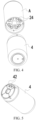
FIG. 1 is a schematic diagram of an aerosol generation device according to an embodiment of this application; -
FIG. 2 is an exploded view of an aerosol generation device according to an embodiment of this application; -
FIG. 3 is a cross-sectional view of an aerosol generation device according to an embodiment of this application; -
FIG. 4 is an exploded view of an aerosol generation device according to another embodiment of this application; -
FIG. 5 is a schematic diagram of a power supply assembly according to an embodiment of this application; -
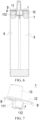
FIG. 6 is another cross-sectional view of an aerosol generation device according to an embodiment of this application; and -
FIG. 7 is a schematic diagram of a mouthpiece according to an embodiment of this application. - In the drawings:
- 1: mouthpiece; 11: second rotating portion; 111: elastic piece; 112: claw; 12: base plate; 13: suction nozzle;
- A: cartridge assembly;
- 2: cartridge; 21: accommodation cavity; 22: first airway; 23: atomizer; 24: first electrode set;
- 3: shell;
- 4: power supply assembly; 41: battery core; 42: second electrode set;
- 5: connecting support;
- 6: airflow channel;
- 7: end cap; 71: second channel; 72: first rotating portion; 721: rotating hole; 73: convex column; 74: groove; 75: support platform;
- 8: elastic member; 81: through hole; 82: annular rib; 83: positioning hole;
- B: control switch; C: striking portion; and D: striking member.
- The following clearly and completely describes the technical solutions in the embodiments of this application with reference to the drawings in the embodiments of this application. Apparently, the described embodiments are some embodiments of this application rather than all of the embodiments. All other embodiments obtained by a person skilled in the art based on the embodiments of this application without creative efforts shall fall within the protection scope of this application.
- In this application, terms "first", "second", and "third" are used merely for the purpose of description, and shall not be construed as indicating or implying relative importance or implying a quantity of indicated technical features. All directional indications (such as up, down, left, right, front, back, ...) in the embodiments of this application are only used to explain relative positional relationship, moving conditions, or the like between components in a specific posture (as shown in the drawings). If the specific posture changes, the directional indications also change accordingly. In addition, the terms "include", "have", and any variant thereof are intended to cover a non-exclusive inclusion. For example, a process, method, system, product, or device that includes a series of steps or units is not limited to the listed steps or units; and instead, further optionally includes a step or unit that is not listed, or further optionally includes another step or unit that is intrinsic to the process, method, product, or device.
- "Embodiment" mentioned in this specification means that particular features, structures, or characteristics described with reference to the embodiment may be included in at least one embodiment of this application. The term appearing at different locations of this specification may not refer to the same embodiment or an independent or alternative embodiment that is mutually exclusive with another embodiment. A person skilled in the art explicitly or implicitly understands that the embodiments described in this specification may be combined with other embodiments.
- It should be noted that, when an element is referred to as "being fixed to" another element, the element may be directly on the other element, or an intervening element may be present. When an element is considered to be "connected to" another element, the element may be directly connected to the other element, or one or more intervening elements may be present. Terms "vertical", "horizontal", "left", and "right" and similar expressions used in this specification are merely used for the purpose of description, and are not a unique implementation.
- Referring to
FIG. 1 to FIG. 3 , an embodiment of this application provides an aerosol generation device. The aerosol generation device includes amouthpiece 1 and a cartridge assembly A including a plurality ofcartridges 2. Eachcartridge 2 may be provided with anaccommodation cavity 21, theaccommodation cavity 21 is for accommodating a liquid substrate that can be atomized to generate aerosol, and a volume of theaccommodation cavity 21 may not exceed 5 ml. Eachcartridge 2 is provided with afirst airway 22. Themouthpiece 1 may rotate relative to the cartridge assembly, to cause themouthpiece 1 to be afirst airway 22 of onecartridge 2 by making themouthpiece 1 rotate relative to the cartridge assembly. Thefirst airway 22 is for transmitting aerosol to themouthpiece 1, and at least part of themouthpiece 1 may be held by a user in the mouth, so that the user can inhale the aerosol by inhaling themouthpiece 1. - Referring to
FIG. 2 , the cartridge assembly A further includes ashell 3. The plurality ofcartridges 2 described above may be held in theshell 3 in parallel with each other. The "plurality of" refers to two or more than two. In the embodiment shown inFIG. 2 , there are fourcartridges 2. However, this is not limited thereto. At least twocartridges 2 in the plurality ofcartridges 2 may be for accommodating different liquid substrates. Different liquid substrates include liquid substrates with different tastes or include liquid substrates with different compositions and ratios, so that different sensory experience can be provided to the user by switching acartridge 2 in communication with themouthpiece 1. Certainly, in an embodiment, liquid substrates accommodated in allcartridges 2 may be the same. - The liquid substrate may include tobacco substance-containing liquid including volatile tobacco flavor components, or may be liquid including non-tobacco substances. The liquid substrate may include water, medicinal liquid, solvent, ethanol, plant extract, spices, flavouring agents, vitamin mixtures, or the like. The spices may include areca nut extract, menthol, peppermint, spearmint oil, various fruity aroma ingredients, and the like, but are not limited thereto. The flavouring agents may include ingredients that can provide various aromas or flavors to the user. The vitamin mixture may be a mixture having at least one of vitamin A, vitamin B, vitamin C, and vitamin E mixed therein, but is not limited thereto. Based on different properties of the liquid substrates, the aerosol generation device may be used in different fields, such as medical treatment, and electronic aerosol atomization.
- At least part of the
shell 3 arranged on a periphery of the plurality ofcartridges 2 may be transparent, so that thecartridges 2 inside can be visually observed through theshell 3. At least part of a wall used to define theaccommodation cavity 21 in thecartridge 2 may also be transparent, so that the inside of thecartridge 2 can be visually observed through theshell 3 and the wall defining theaccommodation cavity 21 in turn. For example, the remaining amount of the liquid substrate in thecartridge 2 is observed, to provide a basis of switching thecartridge 2 in communication with themouthpiece 1 to the user. - In an embodiment, referring to
FIG. 3 , eachcartridge 2 further includes anatomizer 23, theatomizer 23 is in fluid communication with theaccommodation cavity 21, and theatomizer 23 is configured to atomize the liquid substrate. Theatomizer 23 may include a liquid-absorbing element and a heating element. The liquid-absorbing element may be a porous body or fiber, capable of absorbing the liquid substrate and guiding the liquid substrate into an atomization range of the heating element. The heating element is configured to atomize at least part of the liquid substrate on the liquid-absorbing element, to form the aerosol. The heating element may be combined with the liquid-absorbing element, so that the heating element and the heating element can form one unity. In an example, thecartridge 2 may be provided with an atomization compartment in fluid communication with theaccommodation cavity 21, theatomizer 23 is accommodated in the atomization compartment, and thefirst channel 22 is in fluid communication with the atomization compartment. Alternatively, in another example, referring toFIG. 3 , at least part of theatomizer 23 is arranged in thefirst channel 22. - The aerosol generation device further includes a
power supply assembly 4. - The
power supply assembly 4 may include any suitable battery core. In an embodiment, abattery core 41 is a lithium-ion battery. Alternatively, thebattery core 41 may be a nickel metal hydride battery, a nickel-cadmium battery, or a lithium-based battery, such as a lithium cobalt, lithium iron phosphate, lithium titanate, or lithium polymer battery. Thepower supply assembly 4 may include a circuit board and one or more control circuits arranged on the circuit board. The control circuit may control output of thebattery core 41, for example, cause thebattery core 41 to output an alternating current, a direct current, or the like; or for example, cause thebattery core 41 to output a current, a voltage, or the like in a pulse form. - The control circuit may be provided with one or more controllers. The controller may control an entire operation of the aerosol generation device. Specifically, the controller controls operations of the battery core and the cartridge, and may also control an operation of another element in the aerosol generation device. In addition, the controller may determine, by checking a status of an element of the aerosol generation device, whether the aerosol generation device can perform an operation.
- Based on this, in an embodiment, referring to
FIG. 4 and FIG. 5 , the cartridge assembly includes a first electrode set 24, and a second electrode set 42 is arranged on thepower supply assembly 4. There are a plurality of first electrode sets 24. Theatomizer 23 of eachcartridge 2 is exclusively and electrically connected to one first electrode set 24, that is, oneatomizer 23 is electrically connected to only one first electrode set 24, and simultaneously, one first electrode set 24 is electrically connected to only oneatomizer 23, so that a plurality ofatomizers 23 are respectively electrically connected to different first electrode sets 24. A quantity of second electrode sets 42 is less than a quantity of first electrode sets 24, and the cartridge assembly A is rotatably connected to thepower supply assembly 4. When the cartridge assembly A rotates relative to thepower supply assembly 4, a first electrode set 24 rotates relative to a second electrode set 42, and at least one second electrode set 42 may be configured to electrically abut against different first electrode sets 24 in turn in a process in which the cartridge assembly A rotates relative to thepower supply assembly 4. - In an example, there is only one second electrode set 42. The second electrode set 42 is configured to be in electrical communication with a first electrode set 24 that is rotated to and that abuts against the second electrode set 24, so that the
power supply assembly 4 can supply power to anatomizer 23 of only onecartridge 2 at the same moment. It should be noted that, in another example, there may be a plurality of second electrode sets, and the mouthpiece can also be in fluid communication with first airways in the plurality of cartridges simultaneously, so that the power supply assembly can simultaneously supply electric energy to atomizers of the plurality of cartridges, and the user can simultaneously inhale aerosol provided by the plurality of cartridges from the mouthpiece. For example, when there are two second electrode sets, the two second electrode sets may electrically abut against two first electrode sets respectively, so that the power supply assembly simultaneously supplies electric energy to atomizers of two cartridges. In this example, the mouthpiece can be simultaneously in fluid communication with first channels of the two cartridges, so that the user can simultaneously inhale aerosol generated by the two cartridges from the mouthpiece. - The first electrode set 24 and the second electrode set 42 each include at least two electrodes, which may be, for example, an anode and a cathode.
- In an embodiment, the aerosol generation device further includes a
power supply assembly 4 and a control switch electrically connected to thepower supply assembly 4. The control switch is configured to control thepower supply assembly 4 to be in electrical communication with anatomizer 23 of onecartridge 2, so that theatomizer 23 of thecartridge 2 in electrical communication with thepower supply assembly 4 can work to atomize a liquid substrate in thecartridge 2, and generated aerosol is transmitted to themouthpiece 1 through afirst channel 22 of thecartridge 2. However,other cartridges 2 in the cartridge assembly are in a state of electrical disconnection from thepower supply assembly 4. - Based on this, in an example, referring to
FIG. 3 , thepower supply assembly 4 includes a plurality ofbattery cores 41. A quantity ofbattery cores 41 may be consistent with a quantity ofcartridges 2, and the plurality ofbattery cores 41 are electrically connected toatomizers 23 ofdifferent cartridges 2 respectively, so that the plurality ofbattery cores 41 can independently supply power to the plurality ofatomizers 23 respectively in a one-to-one correspondence manner. Therefore, there are a plurality of control switches, or the control switch is a selection switch, so that onebattery core 41 can be controlled to supply power to anatomizer 23 electrically connected to thebattery core 41, and simultaneously,other battery cores 41 andatomizers 23 electrically connected to thebattery cores 41 respectively are in an open circuit state. Based on this example, the aerosol generation device may further include a plurality of connectingsupports 5, each connectingsupport 5 is maintained with onebattery core 41 and acartridge 2 corresponding to thebattery core 41, and thebattery core 41 and thecartridge 2 corresponding to thebattery core 41 form a unity under action of the connectingsupport 5. For example, if the aerosol generation device includes fourcartridges 2 and fourbattery cores 41, there may be four connectingsupports 5, to form four unities. Thebattery core 41 and thecartridge 2 are assembled in theshell 3 as a whole, to facilitate improving assembly efficiency of the aerosol generation device. It should be noted that, in some embodiments, the cartridge assembly A may be configured to be incapable of rotating relative to thepower supply assembly 4. For example, referring toFIG. 3 , theshell 3 of the cartridge assembly A is provided with a near end and a far end that are oppositely arranged. The near end is adjacent to or close to themouthpiece 1, and the far end continues to extend in a direction away from the near end, so that thepower supply assembly 4 is also accommodated in theshell 3. - Alternatively, in another example, referring to
FIG. 3 , the aerosol generation device further includes a plurality ofairflow channels 6 in a one-to-one correspondence with the plurality ofcartridges 2, and eachfirst airway 22 is in exclusive fluid communication with oneairflow channel 6. When the user inhales themouthpiece 1, afirst airway 22 in communication with themouthpiece 1 causes anairflow channel 6 in fluid communication with thefirst airway 22 to have a large airflow speed or a negative pressure. A control switch B is arranged in eachairflow channel 6. The control switch B may be configured to be capable of detecting an airflow speed or a negative pressure of theairflow channel 6, for example, the control switch B may be an atmospheric pressure sensor or an airflow sensor, and the control switch B may be configured to be capable of controlling, based on the airflow speed or the negative pressure of theairflow channel 6, acartridge 2 in fluid communication with theairflow channel 6 to be in electrical communication with thepower supply assembly 4. Therefore, after themouthpiece 1 is in fluid communication with afirst airway 22 of onecartridge 2, when acorresponding airflow channel 6 has airflow with a rapid speed or has a large negative pressure by inhaling themouthpiece 1, the control switch B can automatically control thepower supply assembly 4 to supply electric energy to thecartridge 2 in fluid communication with themouthpiece 1, so that anatomizer 23 of thecartridge 2 atomizes a liquid substrate in thecartridge 2. It should be noted that, in this example, the cartridge assembly A may be configured to be incapable of rotating relative to thepower supply assembly 4. - Referring to
FIG. 1 to FIG. 3 , the aerosol generation device further includes anend cap 7, theend cap 7 is connected to the near end of theshell 3, themouthpiece 1 is rotatably connected to theend cap 7, and themouthpiece 1 rotates relative to theend cap 7 to implement rotation relative to the cartridge assembly A. - The
end cap 7 is provided with a plurality ofsecond channels 71, thefirst channel 22 of eachcartridge 2 is in exclusive fluid communication with onesecond channel 71, and themouthpiece 1 rotates relative to theend cap 7 to be in fluid communication onesecond channel 71 on theend cap 7, so that themouthpiece 1 is in fluid communication with afirst channel 22 in fluid communication with thesecond channel 71. - More specifically, referring to
FIG. 3 andFIG. 6 , theend cap 7 is provided with a first rotatingportion 72, themouthpiece 1 is provided with a secondrotating portion 11, and the second rotatingportion 11 is configured to be rotatably connected to the first rotatingportion 72, so that themouthpiece 1 can rotate relative to theend cap 7. - In an embodiment, referring to
FIG. 3 andFIG. 6 , the first rotatingportion 72 includes arotating hole 721, and the second rotatingportion 11 includes anelastic piece 111 and aclaw 112 connected to theelastic piece 111. At least part of theelastic piece 111 is located in therotating hole 721, and theelastic piece 111 may rotate around a central axis of therotating hole 721 in therotating hole 721. An outer diameter of theclaw 112 is greater than a hole diameter of at least part of therotating hole 721, and theclaw 112 is configured to grip the first rotatingportion 72, so that the second rotatingportion 11 can be prevented from being separated from therotating hole 721. Theelastic piece 111 on the second rotatingportion 11 may be gathered in a direction of the central axis of therotating hole 721 in a process in which the second rotatingportion 11 is inserted into therotating hole 721, and theclaw 112 arranged on theelastic piece 111 approaches the central axis of therotating hole 721 accordingly. This helps the second rotatingportion 72 to be inserted into therotating hole 721, and facilitates assembly themouthpiece 1 and theend cap 7 into a unity. After the second rotatingportion 11 is inserted into place, under spread of elastic force of theelastic piece 111, theclaw 112 arranged on theelastic piece 111 abuts against the first rotatingportion 72 and grips the first rotatingportion 72. Theelastic piece 111 and theclaw 112 on the second rotatingportion 11 can limit displacement of the second rotatingportion 11 along the central axis of therotating hole 721 in an up-down direction. In an example, theclaw 112 may always keep tightly griping the first rotatingportion 72. For example, referring toFIG. 7 , an angle θ between an outer surface of theelastic piece 111 and a near end surface of theclaw 112 is an acute angle or a right angle. For another example, an extension length of theelastic piece 111 along the central axis of therotating hole 721 is less than or equal to a hole depth of therotating hole 721 on the central axis. - Based on this, in an example, the rotating hole is a through hole, and the claw passes through the rotating hole and grips a far end of the first rotating portion outside the rotating hole, that is, the outer diameter of the claw is greater than a hole diameter of any part of the rotating hole. In this example, an extension length of the elastic piece along the central axis of the rotating hole may be equal to the hole depth of the rotating hole on the central axis. In an example, the rotating hole is a through hole or a blind hole, and the claw grips the first rotating portion in the rotating hole, that is, the outer diameter of the claw is greater than only a hole diameter of near end area of the rotating hole or hole diameters of the near end area and a middle area of the rotating hole. In this example, an extension length of the elastic piece along the central axis of the rotating hole may be less than or equal to the hole depth of the rotating hole on the central axis.
- In other embodiments, the second rotating portion may include a rotating hole, and the first rotating portion may include an elastic piece and a claw connected to the elastic piece. At least part of the elastic piece is located in the rotating hole, and the elastic piece may rotate around a central axis of the rotating hole in the rotating hole. An outer diameter of the claw is greater than a hole diameter of at least part of the rotating hole, and the claw is configured to grip the second rotating portion, so that the first rotating portion can be prevented from being separated from the rotating hole.
- It may be understood that, in other embodiments, an extension length of the elastic piece along the central axis of the rotating hole may be greater than a hole depth of the rotating hole on the central axis, so that the mouthpiece can have specific displacement relative to the end cap along the central axis of the rotating hole in an up-down direction.
- Referring to
FIG. 7 , themouthpiece 1 includes abase plate 12 and asuction nozzle 13, thesuction nozzle 13 and the second rotatingportion 11 are respectively arranged on two opposite sides of thebase plate 12, at least part of thesuction nozzle 13 may be held by the user in the mouth, and thebase plate 12, thesuction nozzle 13, and the second rotatingportion 11 may be integrally injection-molded. Thesuction nozzle 13 is arranged away from a central area of thebase plate 12, to ensure that thesuction nozzle 13 is in fluid communication with afirst airway 22 of only onecartridge 2 by making themouthpiece 1 rotate relative to the cartridge assembly. The secondrotating portion 11 may be arranged in the central area of thebase plate 12. - A thickness of the
base plate 12, that is, a minimum distance between a surface of thebase plate 12 adjacent to thesuction nozzle 13 and a surface of thebase plate 12 adjacent to the second rotatingportion 11 may be between 0.5 mm to 3 mm, for example, may be approximately 1.5 mm, so that thebase plate 12 has a smaller thickness, and damage to surface consistency of the aerosol generation device is reduced after themouthpiece 1 is combined with the cartridge assembly. - Referring to
FIG. 2 , the aerosol generation device further includes anelastic member 8. At least part of theelastic member 8 is arranged between theend cap 7 and themouthpiece 1. Theelastic member 8 may be configured to provide resistance to rotation of themouthpiece 1 relative to theend cap 7, to prevent themouthpiece 1 from rotating relative to theend cap 7 when it is not necessary to rotate relative to theend cap 7. - In an embodiment, referring to
FIG. 6 , theelastic member 8 is arranged around the second rotatingportion 11, and elastically squeezes the second rotatingportion 11 transversely. Specifically, theelastic member 8 is fixed on theend cap 7, and the second rotatingportion 11 rubs theelastic member 8 when rotating relative to the first rotatingportion 72; or theelastic member 8 is fixed on themouthpiece 1, and the first rotatingportion 72 rubs theelastic member 8 when the second rotatingportion 11 rotates relative to the first rotatingportion 72. Theelastic member 8 has a larger friction coefficient than the first rotatingportion 72 and the second rotatingportion 11, so that theelastic member 8 can provide resistance to rotation of the second rotatingportion 11 relative to the first rotatingportion 72. - In an embodiment, referring to
FIG. 6 , at least part of theelastic member 8 is longitudinally squeezed by themouthpiece 1 and theend cap 7. Specifically, theelastic member 8 is fixed on theend cap 7, and themouthpiece 1 rubs theelastic member 8 when rotating relative to theend cap 7; or theelastic member 8 is fixed on themouthpiece 1, and theend cap 7 rubs theelastic member 8 when themouthpiece 1 rotates relative to theend cap 7. - In the embodiment shown in
FIG. 2 , theend cap 7 is provided with aconvex column 73, theelastic member 8 is provided with a throughhole 81 corresponding to theconvex column 73, and at least part of theconvex column 73 is embedded into the throughhole 81. Through interference fit between the throughhole 81 and theconvex column 73, theelastic member 8 is fixed on theend cap 7. - A quantity of
convex columns 73 may be equal to or greater than a quantity ofsecond channels 71, and the plurality ofsecond channels 71 are respectively arranged in differentconvex columns 73. Corresponding to the plurality ofconvex columns 73, there may also be a plurality of throughholes 81, and the plurality ofconvex columns 73 are respectively embedded into different throughholes 81. Theelastic member 8 surrounding theconvex columns 73 elastically abuts against themouthpiece 1, for example, abuts against thebase plate 12 of themouthpiece 1, so that theelastic member 8 rubs thebase plate 12 when themouthpiece 1 rotates relative to theend cap 7, so that the plurality ofsecond channels 71 can also be isolated from each other when resistance to relative rotation between themouthpiece 1 and theend cap 7 is provided, to ensure that thesuction nozzle 13 on themouthpiece 1 can be in fluid communication with only onesecond channel 71 simultaneously. - In an example, referring to
FIG. 2 andFIG. 3 , theelastic member 8 may be provided with a plurality ofannular ribs 82, eachannular rib 82 surrounds one throughhole 81, and theelastic member 8 elastically abuts against themouthpiece 1 mainly through theannular ribs 82, for example, elastically abuts against thebase plate 12 of themouthpiece 1. Thebase plate 12 may be provided with a flat abutting surface, the plurality ofannular ribs 82 elastically abut against the abutting surface simultaneously, and the plurality ofannular ribs 82 are slidably connected to the abutting surface, so that when themouthpiece 1 rotates relative to theend cap 7, the plurality ofannular ribs 82 can simultaneously rub the abutting surface. Under action of the plurality ofannular ribs 82 elastically abutting against the abutting surface simultaneously, the plurality ofsecond channels 71 are isolated from each other on a side toward themouthpiece 1. - The
elastic member 8 may also be provided with apositioning hole 83, and the second rotatingportion 11 may pass through thepositioning hole 83 and then rotate and cooperate with the first rotatingportion 72. Therefore, the second rotatingportion 11 may rotate around a central axis of thepositioning hole 83, and thepositioning hole 83 may interfere with the second rotatingportion 11, so that theelastic member 8 can provide transverse elastic abutting action force to the second rotatingportion 11. Theend cap 7 may be provided with agroove 74, thegroove 74 is configured to receive at least part of theelastic member 8, and thegroove 74 also helps to fix theelastic member 8 on theend cap 7. Theend cap 7 may be provided with asupport platform 75 recessed relative to thegroove 74. Thesupport platform 75 is arranged on a periphery of thegroove 74. Thesupport platform 75 may define at least part of a boundary of thegroove 74. An inner side surface of thesupport platform 75 may elastically abut against theelastic member 8. - A near end of the
support platform 75 may support and abut thebase plate 12 of themouthpiece 1, and in a process in which themouthpiece 1 rotates relative to theend cap 7 and in a process in which themouthpiece 1 is still relative to theend cap 7, mutual cooperation between the first rotatingportion 72 and the second rotatingportion 11 can ensure that thesupport platform 75 always abuts against thebase plate 12 of themouthpiece 1, and the mutual cooperation between the first rotatingportion 72 and the second rotatingportion 11 can also ensure that theelastic member 8 always elastically abuts against thebase plate 12 of themouthpiece 1. - In an example, referring to
FIG. 2 , thesupport platform 75 is annular and surrounds a periphery of theelastic member 8. Thesupport platform 75 can hide theelastic member 8, to prevent theelastic member 8 from being exposed to a surface of the aerosol generation device, and can make theelastic member 8 invisible. - A prompting mechanism may be arranged on the aerosol generation device. The prompting mechanism can send out a prompt signal when the
mouthpiece 1 rotates relative to theend cap 7 to be in airflow communication with onesecond channel 71 on theend cap 7. The prompt signal may include a sound signal, a light signal, a vibration signal, or the like. - In an embodiment, the prompting mechanism can provide tactile feedback. Referring to
FIG. 2 andFIG. 7 , one of thesupport platform 75 of theend cap 7 and thebase plate 12 of themouthpiece 1 is provided with striking portions C in a one-to-one correspondence with the plurality ofsecond airways 71, and the other one is provided with at least one striking member D. A quantity of one of striking portions C and striking members D is consistent with a quantity ofsecond airways 71, and a quantity of the other one is one. In the process in which themouthpiece 1 rotates relative to theend cap 7, the at least one striking member D can strike at least one striking portion C, to emit sound (auditory feedback) and/or generate vibration (tactile feedback). The user may determine, based on the sound (auditory feedback) and/or the vibration (tactile feedback), a rotational position of themouthpiece 1 relative to theend cap 7, and determine whether thesuction nozzle 13 of themouthpiece 1 is being in fluid communication with onesecond airway 71. Therefore, after the user senses the prompt signal, continued rotation of themouthpiece 1 relative to theend cap 7 can be stopped. - Based on this, in an example, referring to
FIG. 2 andFIG. 7 , the striking member D may be a hemispherical bump or an elastic steel ball, and the striking portion C may be a hemispherical pit. When at least part of the bump or the elastic steel ball is embedded into the pit through rotation, striking between the bump and the pit produces clicking sound, and simultaneously, themouthpiece 1 and/or theend cap 7 may generate sensible vibration. - It may be understood that, in other examples, when the mouthpiece rotates relative to the end cap to be in airflow communication with one second channel on the end cap, the prompting mechanism can generate a change in an electrical parameter or a magnetic parameter. The circuit board controls a buzzer, a player, an LED light, a vibrator, and the like to issue prompts when detecting the change in the electrical parameter or the magnetic parameter.
- It should be noted that, this specification of this application and the drawings thereof illustrate preferred embodiments of this application, but are not limited to the embodiments described in this specification, furthermore, a person of ordinary skill in the art may make improvements or variations according to the above descriptions, and such improvements and variations shall all fall within the protection scope of the appended claims of this application.
Claims (14)
- An aerosol generation device, comprising:a cartridge assembly (A), comprising a shell (3) and a plurality of cartridges (2), wherein the shell is provided with a near end and a far end that are longitudinally opposite, the plurality of cartridges are accommodated in the shell, and each cartridge is provided with a first channel for airflow to pass through and an accommodation cavity (21) for accommodating a liquid substrate;an end cap (7), connected to the near end of the shell, wherein the end cap is provided with a plurality of second channels, the first channel of each cartridge is correspondingly in exclusive fluid communication with one second channel, and the end cap is provided with a first rotating portion (72); anda mouthpiece (1), provided with a second rotating portion (11), wherein the second rotating portion is configured to be rotatably connected to the first rotating portion (72), to cause the mouthpiece to be selectively in fluid communication with one second channel.
- The aerosol generation device according to claim 1, wherein an elastic member (8) is fixed on at least one of the mouthpiece (1) and the end cap (7), and the elastic member (8) is configured to provide resistance to rotation of the mouthpiece relative to the end cap.
- The aerosol generation device according to claim 2, wherein:the elastic member (8) is arranged around the second rotating portion (11);at least part of the elastic member (8) is longitudinally squeezed by the mouthpiece (1) and the end cap (7); orthe elastic member is provided with a through hole (81), the end cap (7) is provided with a convex column (73), and at least part of the convex column is embedded into the through hole, to fix the elastic member.
- The aerosol generation device according to claim 3, wherein there are a plurality of convex columns (73), and the plurality of second channels are respectively arranged in different convex columns; and
there are a plurality of through holes (81), the plurality of convex columns are respectively embedded into different through holes, and the elastic member elastically abuts against the mouthpiece, to isolate the plurality of second channels from each other. - The aerosol generation device according to claim 3, wherein the elastic member (8) is provided with a plurality of annular ribs (82), each annular rib surrounds one through hole, and the annular rib elastically abuts against the mouthpiece.
- The aerosol generation device according to claim 2, wherein the end cap (7) is provided with a support platform (75), and the support platform always abuts against the mouthpiece, and is slidably connected to the mouthpiece when the mouthpiece rotates relative to the end cap.
- The aerosol generation device according to claim 6, wherein a side of the end cap (7) toward the mouthpiece is provided with a groove (74) recessed relative to the support platform, and at least part of the elastic member is accommodated in the groove.
- The aerosol generation device according to claim 1, wherein a prompting mechanism is arranged on the aerosol generation device, and the prompting mechanism is configured to provide tactile feedback when the mouthpiece (1) rotates to a position at which the mouthpiece is in airflow communication with one second channel.
- The aerosol generation device according to claim 8, wherein the end cap (7) is provided with a support platform (75) and a plurality of second airways, one of the support platform and the mouthpiece is provided with bumps in a one-to-one correspondence with the plurality of second airways, the other one is provided with at least one pit, and when the mouthpiece rotates to be in fluid communication with one second airway, at least one bump is embedded into one pit, to generate tactile feedback.
- The aerosol generation device according to claim 1, wherein the first rotating portion comprises a rotating hole (721), the second rotating portion comprises an elastic piece (111) and a claw (112) connected to the elastic piece, at least part of the elastic piece is located in the rotating hole, an outer diameter of the claw is greater than a hole diameter of at least part of the rotating hole, and the claw is configured to grip the first rotating portion (72).
- The aerosol generation device according to claim 1, wherein each cartridge (2) comprises an atomizer (23) in fluid communication with the accommodation cavity (21) in the cartridge, the atomizer is configured to atomize the liquid substrate to generate aerosol, and the first airway in the cartridge is in fluid communication with the atomizer corresponding to the cartridge to transmit the aerosol.
- The aerosol generation device according to claim 11, wherein:the aerosol generation device further comprises a power supply assembly (4), a second electrode set (42) is arranged on the power supply assembly, the cartridge assembly comprises a plurality of first electrode sets (24), and the atomizer of each cartridge is electrically connected to different first electrode sets, andthe cartridge assembly (A) is rotatably connected to the power supply assembly (4), and the second electrode set (42) is configured to be in electrical communication with a first electrode set (24) that is rotated to and that abuts against the second electrode set; orthe aerosol generation device further comprises a power supply assembly and a control switch (B) electrically connected to the power supply assembly, and the control switch is configured to control the power supply assembly to be in electrical communication with an atomizer (23) of one cartridge (2); orthe aerosol generation device further comprises a power supply assembly (4), the power supply assembly comprises a plurality of battery cores (41), and the plurality of battery cores are electrically connected to atomizers of different cartridges respectively and correspondingly.
- The aerosol generation device according to claim 12, wherein the aerosol generation device further comprises a plurality of airflow channels (6) in a one-to-one correspondence with the plurality of cartridges (2), each airflow channel is in fluid communication with a first channel of a corresponding cartridge, the control switch (B) is arranged in each airflow channel, and the control switch is configured to control, based on an airflow speed or an atmospheric pressure in the airflow channel, the cartridge corresponding to the airflow channel to be in electrical communication with the power supply assembly.
- An aerosol generation device, comprising:a cartridge assembly (A), comprising a shell (3) and a plurality of cartridges (2), wherein the shell is provided with a near end and a far end that are longitudinally opposite, the plurality of cartridges are accommodated in the shell, and each cartridge is provided with a first channel for airflow to pass through and an accommodation cavity (21) for accommodating a liquid substrate;an end cap (7), connected to the near end of the shell, wherein the end cap is provided with a first rotating portion (72); anda mouthpiece (1), provided with a second rotating portion (11), wherein the second rotating portion is configured to be rotatably connected to the first rotating portion, whereinthe first rotating portion (72) comprises a rotating hole (721), the second rotating portion comprises an elastic piece (111) and a claw (112) connected to the elastic piece, at least part of the elastic piece is located in the rotating hole, an outer diameter of the claw is greater than a hole diameter of at least part of the rotating hole, and the claw is configured to grip the first rotating portion.
Priority Applications (1)
| Application Number | Priority Date | Filing Date | Title |
|---|---|---|---|
| EP25202084.7A EP4640087A3 (en) | 2023-05-12 | 2024-03-19 | Aerosol generation device |
Applications Claiming Priority (1)
| Application Number | Priority Date | Filing Date | Title |
|---|---|---|---|
| CN202321163867.XU CN220109154U (en) | 2023-05-12 | 2023-05-12 | Aerosol generating device |
Related Child Applications (2)
| Application Number | Title | Priority Date | Filing Date |
|---|---|---|---|
| EP25202084.7A Division EP4640087A3 (en) | 2023-05-12 | 2024-03-19 | Aerosol generation device |
| EP25202084.7A Division-Into EP4640087A3 (en) | 2023-05-12 | 2024-03-19 | Aerosol generation device |
Publications (2)
| Publication Number | Publication Date |
|---|---|
| EP4461147A1 true EP4461147A1 (en) | 2024-11-13 |
| EP4461147B1 EP4461147B1 (en) | 2025-10-22 |
Family
ID=88890562
Family Applications (2)
| Application Number | Title | Priority Date | Filing Date |
|---|---|---|---|
| EP24164472.3A Active EP4461147B1 (en) | 2023-05-12 | 2024-03-19 | Aerosol generation device |
| EP25202084.7A Pending EP4640087A3 (en) | 2023-05-12 | 2024-03-19 | Aerosol generation device |
Family Applications After (1)
| Application Number | Title | Priority Date | Filing Date |
|---|---|---|---|
| EP25202084.7A Pending EP4640087A3 (en) | 2023-05-12 | 2024-03-19 | Aerosol generation device |
Country Status (3)
| Country | Link |
|---|---|
| EP (2) | EP4461147B1 (en) |
| CN (1) | CN220109154U (en) |
| GB (1) | GB2626093B (en) |
Families Citing this family (7)
| Publication number | Priority date | Publication date | Assignee | Title |
|---|---|---|---|---|
| CN220274894U (en) * | 2023-05-12 | 2024-01-02 | 深圳市合元科技有限公司 | aerosol generating device |
| CN221962861U (en) * | 2023-12-11 | 2024-11-08 | 深圳市合元科技有限公司 | Electronic atomizing device |
| CN221864643U (en) * | 2024-03-01 | 2024-10-22 | 深圳市合元科技有限公司 | Electronic atomizing device |
| US12137736B1 (en) * | 2024-03-08 | 2024-11-12 | PAX Innovations (Shenzhen) Limited | Electronic cigarette having a plurality of e-liquid storage bins |
| CN222443171U (en) * | 2024-05-14 | 2025-02-11 | 深圳雾芯科技有限公司 | Atomizing assembly and atomizing device |
| CN222443170U (en) * | 2024-05-14 | 2025-02-11 | 深圳雾芯科技有限公司 | Atomization device |
| WO2025251784A1 (en) * | 2024-06-06 | 2025-12-11 | 思摩尔国际控股有限公司 | Atomization device and aerosol-generating apparatus |
Citations (3)
| Publication number | Priority date | Publication date | Assignee | Title |
|---|---|---|---|---|
| US20200093184A1 (en) * | 2018-09-25 | 2020-03-26 | Gyre Vapes Llc | Handheld vaporizing device with rotating liquid housing chamber |
| CN212678364U (en) * | 2020-07-09 | 2021-03-12 | 深圳市爱乐米科技有限公司 | Multi-cartridge electronic cigarette |
| US20230000151A1 (en) * | 2020-02-06 | 2023-01-05 | Kt&G Corporation | Aerosol delivering device and aerosol generating device with the same |
Family Cites Families (4)
| Publication number | Priority date | Publication date | Assignee | Title |
|---|---|---|---|---|
| WO2023082098A1 (en) * | 2021-11-10 | 2023-05-19 | 深圳市奇味科技有限公司 | Multi-cartridge electronic cigarette |
| CN216931895U (en) * | 2021-11-10 | 2022-07-12 | 深圳市奇味科技有限公司 | Multi-cartridge electronic cigarette |
| CN218185188U (en) * | 2022-09-26 | 2023-01-03 | 深圳市华鑫宇科技有限公司 | Switching type atomization device |
| CN219679760U (en) * | 2023-01-18 | 2023-09-15 | 深圳市百慕大工业有限公司 | Multi-taste electronic atomizer |
-
2023
- 2023-05-12 CN CN202321163867.XU patent/CN220109154U/en active Active
-
2024
- 2024-03-19 EP EP24164472.3A patent/EP4461147B1/en active Active
- 2024-03-19 EP EP25202084.7A patent/EP4640087A3/en active Pending
- 2024-03-19 GB GB2403898.6A patent/GB2626093B/en active Active
Patent Citations (3)
| Publication number | Priority date | Publication date | Assignee | Title |
|---|---|---|---|---|
| US20200093184A1 (en) * | 2018-09-25 | 2020-03-26 | Gyre Vapes Llc | Handheld vaporizing device with rotating liquid housing chamber |
| US20230000151A1 (en) * | 2020-02-06 | 2023-01-05 | Kt&G Corporation | Aerosol delivering device and aerosol generating device with the same |
| CN212678364U (en) * | 2020-07-09 | 2021-03-12 | 深圳市爱乐米科技有限公司 | Multi-cartridge electronic cigarette |
Also Published As
| Publication number | Publication date |
|---|---|
| GB2626093A (en) | 2024-07-10 |
| EP4640087A2 (en) | 2025-10-29 |
| EP4640087A3 (en) | 2026-01-14 |
| GB2626093B (en) | 2025-01-15 |
| GB202403898D0 (en) | 2024-05-01 |
| CN220109154U (en) | 2023-12-01 |
| EP4461147B1 (en) | 2025-10-22 |
Similar Documents
| Publication | Publication Date | Title |
|---|---|---|
| EP4461147B1 (en) | Aerosol generation device | |
| EP3784077B1 (en) | Electronic aerosol provision system | |
| JP7250159B2 (en) | AEROSOL SUPPLY DEVICE AND AEROSOL GENERATOR WITH SAME | |
| CN220274894U (en) | aerosol generating device | |
| CN220712903U (en) | Aerosol generating device | |
| KR102548516B1 (en) | Aerosol generating apparatus | |
| KR20140090138A (en) | Low temperature electronic vaporization device and methods | |
| EP4527218A2 (en) | Aerosol generation device | |
| KR102477681B1 (en) | Aerosol generating apparatus | |
| KR20210009309A (en) | Aerosol generating device comprising two nebulizer assemblies | |
| KR20210158699A (en) | Aerosol generating apparatus | |
| CN213879307U (en) | Aerosol Generation System and Charging Case | |
| WO2021224617A1 (en) | Power management for aerosol provision device | |
| KR102586969B1 (en) | Aerosol generating device | |
| CN210782933U (en) | Electrically heated smoking system | |
| CN109757781B (en) | Heater, cartridge and atomizer | |
| CN222109279U (en) | Aerosol generating device | |
| WO2020117338A1 (en) | Portable smoking cessation device with replaceable battery | |
| CN221962871U (en) | Aerosol Generating Device | |
| CN220875920U (en) | Aerosol generating device | |
| EP4505886A1 (en) | Aerosol generation device | |
| KR102533272B1 (en) | Power supply device and aerosol generating system including the same | |
| CN222583653U (en) | A power supply device for electronic atomization and an electronic atomization component | |
| CN218073471U (en) | Atomizer and aerosol-generating device | |
| CN222303089U (en) | Aerosol generating device |
Legal Events
| Date | Code | Title | Description |
|---|---|---|---|
| PUAI | Public reference made under article 153(3) epc to a published international application that has entered the european phase |
Free format text: ORIGINAL CODE: 0009012 |
|
| STAA | Information on the status of an ep patent application or granted ep patent |
Free format text: STATUS: REQUEST FOR EXAMINATION WAS MADE |
|
| 17P | Request for examination filed |
Effective date: 20240319 |
|
| AK | Designated contracting states |
Kind code of ref document: A1 Designated state(s): AL AT BE BG CH CY CZ DE DK EE ES FI FR GB GR HR HU IE IS IT LI LT LU LV MC ME MK MT NL NO PL PT RO RS SE SI SK SM TR |
|
| REG | Reference to a national code |
Ref country code: DE Ref legal event code: R079 Free format text: PREVIOUS MAIN CLASS: A24F0040100000 Ipc: A24F0040300000 Ref country code: DE Ref legal event code: R079 Ref document number: 602024000987 Country of ref document: DE Free format text: PREVIOUS MAIN CLASS: A24F0040100000 Ipc: A24F0040300000 |
|
| GRAP | Despatch of communication of intention to grant a patent |
Free format text: ORIGINAL CODE: EPIDOSNIGR1 |
|
| STAA | Information on the status of an ep patent application or granted ep patent |
Free format text: STATUS: GRANT OF PATENT IS INTENDED |
|
| RIC1 | Information provided on ipc code assigned before grant |
Ipc: A24F 40/10 20200101ALN20250415BHEP Ipc: A24F 40/60 20200101ALI20250415BHEP Ipc: A24F 40/485 20200101ALI20250415BHEP Ipc: A24F 40/40 20200101ALI20250415BHEP Ipc: A24F 40/30 20200101AFI20250415BHEP |
|
| RIC1 | Information provided on ipc code assigned before grant |
Ipc: A24F 40/10 20200101ALN20250508BHEP Ipc: A24F 40/60 20200101ALI20250508BHEP Ipc: A24F 40/485 20200101ALI20250508BHEP Ipc: A24F 40/40 20200101ALI20250508BHEP Ipc: A24F 40/30 20200101AFI20250508BHEP |
|
| INTG | Intention to grant announced |
Effective date: 20250520 |
|
| RIC1 | Information provided on ipc code assigned before grant |
Ipc: A24F 40/10 20200101ALN20250513BHEP Ipc: A24F 40/60 20200101ALI20250513BHEP Ipc: A24F 40/485 20200101ALI20250513BHEP Ipc: A24F 40/40 20200101ALI20250513BHEP Ipc: A24F 40/30 20200101AFI20250513BHEP |
|
| GRAS | Grant fee paid |
Free format text: ORIGINAL CODE: EPIDOSNIGR3 |
|
| GRAA | (expected) grant |
Free format text: ORIGINAL CODE: 0009210 |
|
| STAA | Information on the status of an ep patent application or granted ep patent |
Free format text: STATUS: THE PATENT HAS BEEN GRANTED |
|
| AK | Designated contracting states |
Kind code of ref document: B1 Designated state(s): AL AT BE BG CH CY CZ DE DK EE ES FI FR GB GR HR HU IE IS IT LI LT LU LV MC ME MK MT NL NO PL PT RO RS SE SI SK SM TR |
|
| REG | Reference to a national code |
Ref country code: CH Ref legal event code: F10 Free format text: ST27 STATUS EVENT CODE: U-0-0-F10-F00 (AS PROVIDED BY THE NATIONAL OFFICE) Effective date: 20251022 Ref country code: GB Ref legal event code: FG4D |
|
| REG | Reference to a national code |
Ref country code: DE Ref legal event code: R096 Ref document number: 602024000987 Country of ref document: DE |
|
| REG | Reference to a national code |
Ref country code: IE Ref legal event code: FG4D |
|
| REG | Reference to a national code |
Ref country code: NL Ref legal event code: MP Effective date: 20251022 |
|
| PG25 | Lapsed in a contracting state [announced via postgrant information from national office to epo] |
Ref country code: NL Free format text: LAPSE BECAUSE OF FAILURE TO SUBMIT A TRANSLATION OF THE DESCRIPTION OR TO PAY THE FEE WITHIN THE PRESCRIBED TIME-LIMIT Effective date: 20251022 |
|
| PG25 | Lapsed in a contracting state [announced via postgrant information from national office to epo] |
Ref country code: ES Free format text: LAPSE BECAUSE OF FAILURE TO SUBMIT A TRANSLATION OF THE DESCRIPTION OR TO PAY THE FEE WITHIN THE PRESCRIBED TIME-LIMIT Effective date: 20251022 |
|
| REG | Reference to a national code |
Ref country code: LT Ref legal event code: MG9D |
|
| PG25 | Lapsed in a contracting state [announced via postgrant information from national office to epo] |
Ref country code: NO Free format text: LAPSE BECAUSE OF FAILURE TO SUBMIT A TRANSLATION OF THE DESCRIPTION OR TO PAY THE FEE WITHIN THE PRESCRIBED TIME-LIMIT Effective date: 20260122 |
|
| PGFP | Annual fee paid to national office [announced via postgrant information from national office to epo] |
Ref country code: DE Payment date: 20260313 Year of fee payment: 3 |
|
| PG25 | Lapsed in a contracting state [announced via postgrant information from national office to epo] |
Ref country code: HR Free format text: LAPSE BECAUSE OF FAILURE TO SUBMIT A TRANSLATION OF THE DESCRIPTION OR TO PAY THE FEE WITHIN THE PRESCRIBED TIME-LIMIT Effective date: 20251022 Ref country code: AT Free format text: LAPSE BECAUSE OF FAILURE TO SUBMIT A TRANSLATION OF THE DESCRIPTION OR TO PAY THE FEE WITHIN THE PRESCRIBED TIME-LIMIT Effective date: 20251022 Ref country code: FI Free format text: LAPSE BECAUSE OF FAILURE TO SUBMIT A TRANSLATION OF THE DESCRIPTION OR TO PAY THE FEE WITHIN THE PRESCRIBED TIME-LIMIT Effective date: 20251022 |
|
| PGFP | Annual fee paid to national office [announced via postgrant information from national office to epo] |
Ref country code: AT Payment date: 20260301 Year of fee payment: 3 |
|
| REG | Reference to a national code |
Ref country code: AT Ref legal event code: MK05 Ref document number: 1848358 Country of ref document: AT Kind code of ref document: T Effective date: 20251022 |
|
| PG25 | Lapsed in a contracting state [announced via postgrant information from national office to epo] |
Ref country code: RS Free format text: LAPSE BECAUSE OF FAILURE TO SUBMIT A TRANSLATION OF THE DESCRIPTION OR TO PAY THE FEE WITHIN THE PRESCRIBED TIME-LIMIT Effective date: 20260122 |
|
| PG25 | Lapsed in a contracting state [announced via postgrant information from national office to epo] |
Ref country code: IS Free format text: LAPSE BECAUSE OF FAILURE TO SUBMIT A TRANSLATION OF THE DESCRIPTION OR TO PAY THE FEE WITHIN THE PRESCRIBED TIME-LIMIT Effective date: 20260222 |
|
| PGFP | Annual fee paid to national office [announced via postgrant information from national office to epo] |
Ref country code: FR Payment date: 20260330 Year of fee payment: 3 |
|
| PG25 | Lapsed in a contracting state [announced via postgrant information from national office to epo] |
Ref country code: PT Free format text: LAPSE BECAUSE OF FAILURE TO SUBMIT A TRANSLATION OF THE DESCRIPTION OR TO PAY THE FEE WITHIN THE PRESCRIBED TIME-LIMIT Effective date: 20260223 |
|
| PG25 | Lapsed in a contracting state [announced via postgrant information from national office to epo] |
Ref country code: PL Free format text: LAPSE BECAUSE OF FAILURE TO SUBMIT A TRANSLATION OF THE DESCRIPTION OR TO PAY THE FEE WITHIN THE PRESCRIBED TIME-LIMIT Effective date: 20251022 |
|
| PG25 | Lapsed in a contracting state [announced via postgrant information from national office to epo] |
Ref country code: LV Free format text: LAPSE BECAUSE OF FAILURE TO SUBMIT A TRANSLATION OF THE DESCRIPTION OR TO PAY THE FEE WITHIN THE PRESCRIBED TIME-LIMIT Effective date: 20251022 |
|
| PG25 | Lapsed in a contracting state [announced via postgrant information from national office to epo] |
Ref country code: BG Free format text: LAPSE BECAUSE OF FAILURE TO SUBMIT A TRANSLATION OF THE DESCRIPTION OR TO PAY THE FEE WITHIN THE PRESCRIBED TIME-LIMIT Effective date: 20251022 |