EP4461114A1 - Detection of slip between a self-propelled robotic tool and a grass surface - Google Patents
Detection of slip between a self-propelled robotic tool and a grass surface Download PDFInfo
- Publication number
- EP4461114A1 EP4461114A1 EP24161698.6A EP24161698A EP4461114A1 EP 4461114 A1 EP4461114 A1 EP 4461114A1 EP 24161698 A EP24161698 A EP 24161698A EP 4461114 A1 EP4461114 A1 EP 4461114A1
- Authority
- EP
- European Patent Office
- Prior art keywords
- drive
- drive signal
- wheel
- self
- time
- Prior art date
- Legal status (The legal status is an assumption and is not a legal conclusion. Google has not performed a legal analysis and makes no representation as to the accuracy of the status listed.)
- Pending
Links
- 244000025254 Cannabis sativa Species 0.000 title claims abstract description 24
- 238000001514 detection method Methods 0.000 title description 3
- 238000000034 method Methods 0.000 claims abstract description 59
- 238000004590 computer program Methods 0.000 claims description 11
- 238000012545 processing Methods 0.000 claims description 6
- 230000004044 response Effects 0.000 claims description 5
- 238000003860 storage Methods 0.000 claims description 4
- 230000008569 process Effects 0.000 description 22
- 230000006870 function Effects 0.000 description 8
- 230000001133 acceleration Effects 0.000 description 6
- 238000010586 diagram Methods 0.000 description 6
- 230000006399 behavior Effects 0.000 description 2
- 230000008901 benefit Effects 0.000 description 2
- 238000005259 measurement Methods 0.000 description 2
- 230000009467 reduction Effects 0.000 description 2
- 230000003252 repetitive effect Effects 0.000 description 2
- 230000005540 biological transmission Effects 0.000 description 1
- 230000008859 change Effects 0.000 description 1
- 238000004891 communication Methods 0.000 description 1
- 238000012937 correction Methods 0.000 description 1
- 238000005520 cutting process Methods 0.000 description 1
- 238000005265 energy consumption Methods 0.000 description 1
- 238000005516 engineering process Methods 0.000 description 1
- 230000000737 periodic effect Effects 0.000 description 1
- 238000005096 rolling process Methods 0.000 description 1
- 238000009987 spinning Methods 0.000 description 1
- 239000011800 void material Substances 0.000 description 1
Images



Classifications
-
- G—PHYSICS
- G05—CONTROLLING; REGULATING
- G05D—SYSTEMS FOR CONTROLLING OR REGULATING NON-ELECTRIC VARIABLES
- G05D1/00—Control of position, course, altitude or attitude of land, water, air or space vehicles, e.g. using automatic pilots
- G05D1/80—Arrangements for reacting to or preventing system or operator failure
- G05D1/86—Monitoring the performance of the system, e.g. alarm or diagnosis modules
-
- A—HUMAN NECESSITIES
- A01—AGRICULTURE; FORESTRY; ANIMAL HUSBANDRY; HUNTING; TRAPPING; FISHING
- A01D—HARVESTING; MOWING
- A01D34/00—Mowers; Mowing apparatus of harvesters
- A01D34/006—Control or measuring arrangements
- A01D34/008—Control or measuring arrangements for automated or remotely controlled operation
-
- A—HUMAN NECESSITIES
- A01—AGRICULTURE; FORESTRY; ANIMAL HUSBANDRY; HUNTING; TRAPPING; FISHING
- A01D—HARVESTING; MOWING
- A01D69/00—Driving mechanisms or parts thereof for harvesters or mowers
- A01D69/02—Driving mechanisms or parts thereof for harvesters or mowers electric
-
- B—PERFORMING OPERATIONS; TRANSPORTING
- B60—VEHICLES IN GENERAL
- B60L—PROPULSION OF ELECTRICALLY-PROPELLED VEHICLES; SUPPLYING ELECTRIC POWER FOR AUXILIARY EQUIPMENT OF ELECTRICALLY-PROPELLED VEHICLES; ELECTRODYNAMIC BRAKE SYSTEMS FOR VEHICLES IN GENERAL; MAGNETIC SUSPENSION OR LEVITATION FOR VEHICLES; MONITORING OPERATING VARIABLES OF ELECTRICALLY-PROPELLED VEHICLES; ELECTRIC SAFETY DEVICES FOR ELECTRICALLY-PROPELLED VEHICLES
- B60L3/00—Electric devices on electrically-propelled vehicles for safety purposes; Monitoring operating variables, e.g. speed, deceleration or energy consumption
- B60L3/10—Indicating wheel slip ; Correction of wheel slip
-
- B—PERFORMING OPERATIONS; TRANSPORTING
- B60—VEHICLES IN GENERAL
- B60L—PROPULSION OF ELECTRICALLY-PROPELLED VEHICLES; SUPPLYING ELECTRIC POWER FOR AUXILIARY EQUIPMENT OF ELECTRICALLY-PROPELLED VEHICLES; ELECTRODYNAMIC BRAKE SYSTEMS FOR VEHICLES IN GENERAL; MAGNETIC SUSPENSION OR LEVITATION FOR VEHICLES; MONITORING OPERATING VARIABLES OF ELECTRICALLY-PROPELLED VEHICLES; ELECTRIC SAFETY DEVICES FOR ELECTRICALLY-PROPELLED VEHICLES
- B60L3/00—Electric devices on electrically-propelled vehicles for safety purposes; Monitoring operating variables, e.g. speed, deceleration or energy consumption
- B60L3/10—Indicating wheel slip ; Correction of wheel slip
- B60L3/102—Indicating wheel slip ; Correction of wheel slip of individual wheels
-
- B—PERFORMING OPERATIONS; TRANSPORTING
- B60—VEHICLES IN GENERAL
- B60W—CONJOINT CONTROL OF VEHICLE SUB-UNITS OF DIFFERENT TYPE OR DIFFERENT FUNCTION; CONTROL SYSTEMS SPECIALLY ADAPTED FOR HYBRID VEHICLES; ROAD VEHICLE DRIVE CONTROL SYSTEMS FOR PURPOSES NOT RELATED TO THE CONTROL OF A PARTICULAR SUB-UNIT
- B60W40/00—Estimation or calculation of non-directly measurable driving parameters for road vehicle drive control systems not related to the control of a particular sub unit, e.g. by using mathematical models
- B60W40/02—Estimation or calculation of non-directly measurable driving parameters for road vehicle drive control systems not related to the control of a particular sub unit, e.g. by using mathematical models related to ambient conditions
- B60W40/06—Road conditions
- B60W40/064—Degree of grip
-
- A—HUMAN NECESSITIES
- A01—AGRICULTURE; FORESTRY; ANIMAL HUSBANDRY; HUNTING; TRAPPING; FISHING
- A01D—HARVESTING; MOWING
- A01D2101/00—Lawn-mowers
-
- B—PERFORMING OPERATIONS; TRANSPORTING
- B60—VEHICLES IN GENERAL
- B60L—PROPULSION OF ELECTRICALLY-PROPELLED VEHICLES; SUPPLYING ELECTRIC POWER FOR AUXILIARY EQUIPMENT OF ELECTRICALLY-PROPELLED VEHICLES; ELECTRODYNAMIC BRAKE SYSTEMS FOR VEHICLES IN GENERAL; MAGNETIC SUSPENSION OR LEVITATION FOR VEHICLES; MONITORING OPERATING VARIABLES OF ELECTRICALLY-PROPELLED VEHICLES; ELECTRIC SAFETY DEVICES FOR ELECTRICALLY-PROPELLED VEHICLES
- B60L2240/00—Control parameters of input or output; Target parameters
- B60L2240/40—Drive Train control parameters
- B60L2240/46—Drive Train control parameters related to wheels
- B60L2240/465—Slip
-
- B—PERFORMING OPERATIONS; TRANSPORTING
- B60—VEHICLES IN GENERAL
- B60W—CONJOINT CONTROL OF VEHICLE SUB-UNITS OF DIFFERENT TYPE OR DIFFERENT FUNCTION; CONTROL SYSTEMS SPECIALLY ADAPTED FOR HYBRID VEHICLES; ROAD VEHICLE DRIVE CONTROL SYSTEMS FOR PURPOSES NOT RELATED TO THE CONTROL OF A PARTICULAR SUB-UNIT
- B60W2520/00—Input parameters relating to overall vehicle dynamics
- B60W2520/26—Wheel slip
-
- G—PHYSICS
- G05—CONTROLLING; REGULATING
- G05D—SYSTEMS FOR CONTROLLING OR REGULATING NON-ELECTRIC VARIABLES
- G05D17/00—Control of torque; Control of mechanical power
- G05D17/02—Control of torque; Control of mechanical power characterised by the use of electric means
-
- G—PHYSICS
- G05—CONTROLLING; REGULATING
- G05D—SYSTEMS FOR CONTROLLING OR REGULATING NON-ELECTRIC VARIABLES
- G05D2107/00—Specific environments of the controlled vehicles
- G05D2107/20—Land use
- G05D2107/23—Gardens or lawns
Definitions
- the present invention relates to a method of detecting slip between a self-propelled robotic tool and a grass surface.
- the invention further relates to a self-propelled robotic tool, as well as data processing equipment, configured to carry out the method, along with a computer program product implementing the method and a computer-readable storage medium storing the computer program product.
- Self-propelled robotic tools such as robotic lawnmowers autonomously operate unattended within a work area. It may happen that such a robotic tool gets stuck at an obstacle. If the wheels keep on spinning, the grass surface may be damaged. For this and other reasons, most robotic lawnmowers are provided with sensors for detecting collisions and/or wheel slip. There are various known methods for detecting the wheel slip of a robotic lawnmower. For example, US 2014/330496 A1 suggests that wheel slippage can be detected based on the drive current to a drive wheel falling below a certain value.
- a problem with the method of US 2014/330496 A1 is that it does not work very well in situations where the friction between grass and drive wheels is intrinsically low. This may be the case for e.g. low-weight robotic lawnmowers, for lawnmowers driving on wet grass, or if wheels having smooth or fine-patterned rolling surfaces, intended for delicate grass surfaces, are used. This can in principle be addressed by adding dead weight to the lawnmowers. However, adding weight is not a satisfactory solution, because it increases the energy consumption of the robotic lawnmower. As the robotic lawnmower market matures, there is also a trend towards less complex and less expensive robotic lawnmowers.
- a method of detecting slip between a self-propelled robotic tool and a grass surface comprising: driving on the grass surface; based on a desired heading and speed of the self-propelled robotic tool, generating a first drive signal for a first drive wheel of the self-propelled robotic tool; generating a time-variant drive signal pattern overlay; applying said time-variant drive signal pattern overlay to said first drive signal to form a first wheel control signal; operating a first drive wheel based on said first wheel control signal; receiving a movement signal from a movement detector; and determining a slip state based on an identification of said time-variant drive signal pattern overlay in said movement signal.
- the time-variant drive signal pattern overlay may, for example, be a repetitive signal such as a periodic signal of a set frequency.
- the identification may, for example, be made by using a band-pass filter with its pass band at the set frequency.
- the set frequency may be predetermined; alternatively, it may be dynamically set, and the pass band of the band pass filter may be dynamically adjusted accordingly.
- the time-variant drive signal pattern overlay may comprise consecutive velocity ramps of opposite signs, and the identification of the time-variant drive signal pattern overlay may comprise the identification of consecutive sets of accelerations and decelerations.
- the time-variant drive signal pattern overlay may comprise a step function, and the identification may comprise the identification of a corresponding acceleration or retardation peak.
- the time-variant drive signal pattern overlay may have any other suitable pattern, and may be identified using any other suitable signal identification technique, such as a trained classifier trained on the specific pattern.
- the time-variant drive signal pattern overlay may be predetermined; alternatively, it may be generated based on a predetermined algorithm. Still alternatively, it may be void of any specific predetermined character, for example using a random function.
- the identification of the time-variant drive signal pattern overlay in said movement signal may be based on a comparison with a stored copy of the time-variant drive signal pattern overlay.
- the slip state may be binary, its binary values corresponding to "slip detected” and "slip not detected”. Alternatively, the slip state may be represented as a probability or likelihood that the self-propelled robotic tool is slipping.
- the method may further comprise: based on said desired heading and speed of the self-propelled robotic tool, generating a second drive signal for a second drive wheel of the self-propelled robotic tool; applying a time-variant drive signal pattern overlay to said second drive signal to form a second wheel control signal; and operating a second drive wheel based on said second wheel control signal.
- the time-variant drive signal pattern overlay applied to the second drive signal for the second drive wheel may be the same as the time-variant drive signal pattern overlay applied to the first drive signal for the first drive wheel. Alternatively, it may be different.
- the generation of a time-variant drive signal pattern overlay may comprise generating a first time-variant drive signal pattern overlay for the first drive signal and generating a second, different, time-variant drive signal pattern overlay for the second drive signal, and the determination of a slip state may be based on an identification, in said movement signal, of a first time-variant drive signal pattern overlay applied to the first drive signal and a second time-variant drive signal pattern overlay applied to the second drive signal.
- the method may comprise applying the same time-variant drive signal pattern overlay to each of said first and second drive signals. Thereby, identification of the time-variant drive signal pattern overlay in the movement signal may be facilitated.
- the time-variant drive signal pattern overlay applied to the first drive signal may be in phase with the time-variant drive signal pattern overlay applied to the second drive signal.
- the time-variant drive signal pattern overlay applied to the first drive signal may be out of phase with the time-variant drive signal pattern overlay applied to the second drive signal. This results in a change of the self-propelled robotic tool's heading. Such changes are easy to detect, which may facilitate the determination of a slip state based on an identification of the time-variant drive signal pattern overlay in the movement signal.
- the time-variant drive signal pattern overlay of the first wheel control signal may be different from any time-variant drive signal pattern overlay of any second wheel control signal. Such an embodiment results in time-variant deviations of the self-propelled robotic tool's heading.
- different time-variant drive signal pattern overlays may be applied to different drive signals destined for different drive wheels.
- a time-variant drive signal pattern overlay is applied to a single drive signal, destined for a single drive wheel, only.
- a determination that the self-propelled robotic tool is slipping is based on a further condition that no lift has been detected.
- Lift may be detected by e.g. separate lift sensors, by detecting a vertical acceleration, or by any other suitable method.
- the method may further comprise: determining a drive wheel rotation resistance; comparing the drive wheel rotation resistance to a reference resistance value; and based on said comparison, determining that the self-propelled robotic tool has not been lifted.
- the drive wheel rotation resistance may be represented by a wheel drive motor current for turning the drive wheel.
- the reference resistance value may be predetermined. Alternatively, it may be dynamically set. For example, the reference resistance value may be set based on the inclination of the ground upon which the self-propelled robotic tool operates.
- said time-variant drive signal pattern overlay alternates between positive and negative values. Thereby, said time-variant drive signal pattern overlay does not, over time, result in a substantial drift of the path from an intended path corresponding to said first drive signal. According to embodiments, an average value of said time-variant drive signal pattern overlay, over time, is about zero.
- said time-variant drive signal pattern overlay varies with a frequency of between 0,1 Hz and 100 Hz.
- a frequency range is well adapted to the dynamics of a self-propelled robotic tool such as a robotic lawnmower, and results in a movement signal which is easy to detect.
- the frequency may be constant or variable.
- a magnitude of the time-variant drive signal pattern overlay is less than 20% of a magnitude of the first drive signal. Thereby, the behaviour of the self-propelled robotic tool will not look erratic to an observer.
- the magnitude may, for example, correspond to a certain drive current level.
- the magnitude of the time-variant drive signal pattern overlay may be less than 10% of a magnitude of the first drive signal.
- said movement detector comprises at least one of an accelerometer, a gyroscope, and a magnetometer.
- the movement detector may comprise two or more different ones of the mentioned kinds of sensors.
- the sensors may be integrated into an inertial measurement unit, IMU.
- the method may further comprise: in response to having determined that the self-propelled robotic tool is slipping, reversing a rotation direction of said first drive wheel. Thereby, the self-propelled robotic tool will reverse or turn away from any obstacle that may have caused the slip.
- the rotation direction of any second drive wheel may also be rotated.
- data processing equipment comprising at least one processor and memory, configured to carry out the method as defined in any of the embodiments hereinabove.
- a self-propelled robotic tool comprising: a first drive wheel; a first drive wheel motor configured to rotate said first drive wheel; a movement detector; and data processing equipment as defined hereinabove.
- the self-propelled robotic tool further comprises a second drive wheel and, in addition to the first and second drive wheels, at least one further wheel configured to roll on the grass surface, wherein all of said first and second drive wheels and said at least one further wheel are carried by a single, rigid chassis.
- Low-weight lawnmowers are usually of the aforesaid single-chassis type, whereby all wheels are mounted to the same rigid chassis, and thereby particularly benefit from the slip detection methods defined herein.
- the self-propelled robotic tool has a weight of less than 9,0 kg. According to further embodiments, the self-propelled robotic tool has a weight of less than 7,0 kg; according to still further embodiments, the self-propelled robotic tool weighs 5,5 kg or less.
- a computer program product comprising instructions which, when the program is executed on a processor, carries out the method as defined in any of the embodiments hereinabove.
- a computer-readable storage medium having stored thereon the computer program product defined hereinabove.
- Fig. 1 schematically illustrates an overview of a robotic tool system 10 configured to perform a task within a work area 12 such as a garden, a park or a golf course.
- the robotic tool system 10 comprises a battery-powered, self-propelled, and autonomously navigating robotic tool 14, along with a charging station 16 for charging a battery of the self-propelled robotic tool 14.
- the self-propelled robotic tool 14 is configured to drive on a grass surface 17 of the work area 12 while performing a task.
- the robotic tool 14 may be a robotic lawnmower, and for the sake of simplicity, it will be referred to as such in the following.
- the present disclosure may also be useful in connection with self-propelled robotic tools configured as golf ball collecting tools, agricultural machinery, mine clearance robots, or any other type of self-propelled robotic tools that are required to navigate across a grass surface to perform its task.
- teachings herein may be of particular use in robotic tools configured to execute a task over an area to be treated, wherein a full or at least predetermined coverage of the area to be treated is desired.
- the work area 12 may be delimited by a boundary 15 which may be physical, i.e. defined by physical obstacles or a boundary cable carrying a boundary signal, or virtual, i.e. based on positions of boundary segments in a map used by the robotic lawnmower 14 for navigating.
- Fig. 2 illustrates the robotic lawnmower 14 from below.
- the robotic lawnmower 14 is provided with wheels 18a, 18b, 20a, 20b for moving within the work area 12.
- the robotic lawnmower 14 has two drive wheels 18a, 18b for propelling the robotic lawnmower 14, and two non-driven wheels 20a, 20b of caster type.
- the drive wheels 18a, 18b are connected to one or several motors, such an electric motor, either directly or via a transmission (not illustrated), for propelling the robotic lawnmower 14 across the grass surface 17 ( Fig. 1 ).
- the robotic lawnmower 14 mainly propels itself in a forward direction F while cutting grass, even though it may be capable of occasionally reversing in a rearward direction R, for example in response to collisions with objects.
- the drive wheels 18a-b are the rear wheels of the robotic lawnmower 14
- the non-driven wheels 20a-b are the front wheels of the robotic lawnmower 14.
- All wheels 18a, 18b, 20a, 20b are mounted to a single chassis 14a, which is configured as a rigid plastic shell enclosing electronic components of the robotic lawnmower 14.
- a cover 14b encloses an upper portion of the chassis 14a.
- a robotic tool also typically comprises at least one work implement configured to perform the task on the area to be treated.
- the work implement is a grass cutter 22, which may be rotatable about a vertical axis.
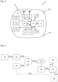
- Fig. 3 illustrates functional blocks of the robotic lawnmower 14 seen from above.
- a first drive wheel 18a is connected to a first electric wheel drive motor 24a
- a second drive wheel 18b is connected to a second electric wheel drive motor 24b.
- the robotic lawnmower 14 further comprises an electronic controller 26.
- the controller 26 is connected to sensors, actuators, and communication interfaces of various kinds, and may be implemented using a central processing unit, CPU, executing instructions stored on a memory 28 which may be external or internal to the controller 26.
- the controller 26 is configured to read instructions from the memory 28 and execute these instructions, in view of different sensor signals, to control the operation of the robotic lawnmower 14.
- the controller 26 is configured to, based on the instructions, control the robotic lawnmower 14 to navigate the work area 12 and perform its task in an autonomous or semi-autonomous manner, i,e. with no, or only occasional, instructions from a human operator.
- the controller 26 also controls the operation of a cutter motor 30, which is configured to drive the grass cutter 22 ( Fig. 2 ).
- a wireless transceiver 32 is connected to the controller 26, and allows the controller 26 to communicate with the charging station 16 ( Fig. 1 ) or any other device, such as a remote control or a smart phone (not shown). Accordingly, the controller 26 and/or memory 28 may alternatively be located in any other part of the robotic tool system 10, such as the charging station 16, which may autonomously direct the operation of the robotic lawnmower 14.
- the robotic lawnmower 14 further comprises a movement detector 33 comprising an inertial measurement unit, IMU, 34.
- the IMU 34 which is rigidly connected to the chassis 14a ( Fig. 2 ), comprises an accelerometer 36, a gyroscope 38, and a magnetometer 40.
- the IMU 34 detects relative movements of the robotic lawnmower 14, and assists the robotic lawnmower 14 to keep track of its movement within the area 12 to be mowed.
- the robotic lawnmower 14 also comprises a GNSS (Global Navigation Satellite System) receiver 42.
- GNSS Global Navigation Satellite System
- the GNSS receiver is configured to receive navigation signals from navigation satellite systems such as GPS, and thereby enables absolute positioning within the work area; as such, the GNSS receiver may be seen as a part of the movement detector 34.
- the GNSS satellite signals may be supplemented by correction signals from one or several local beacons, or over a network, which may enable RTK (real-time kinematic) enhanced GNSS navigation.
- a local RTK beacon may e.g. be arranged in the charging station 16 ( Fig. 1 ).
- the robotic lawnmower 14 further comprises a boundary sensor 35 configured to detect the boundary 15 ( Fig. 1 ) of the work area 12.
- the boundary sensor 35 may, for example, comprise an inductor configured to detect a magnetic field generated by electric current in a boundary cable.
- the controller 26 controls the wheel drive motors 24a, 24b, thereby controlling the propulsion of the robotic lawnmower 14 within the work area 12 to be mowed.
- the wheel drive motors 24a, 24b may be stepper motors, allowing the controller 26 to precisely control the speed and rotation of the respective wheel drive motors 24a, 24b, and thereby also to keep track of the speed and distance travelled by the robotic lawnmower 14, as well as any turning angle of the robotic lawnmower 14 when the wheel drive motors 24a, 24b are operated at different speeds or in reverse directions.
- the controller 26, movement detector 33, boundary sensor 35, transceiver 32, wheel drive motors 24a, 24b, and cutter motor 30 are powered by a battery 44, which is typically situated between the drive wheels 18a, 18b for a maximum of weight and traction on the drive wheels 18a, 18b.
- the robotic lawnmower 14 is configured to navigate to the charging station 16 ( Fig. 1 ) on a regular basis, for example between work sessions and/or whenever the battery charge is running low, in order to dock with the charging station 16 for recharging the battery 44.
- the charging station 16 may be connected so as to receive power from the electric power grid.
- the robotic lawnmower 14 ( Fig. 3 ) is configured to perform a method of detecting slip of the drive wheels 18a, 18b.
- the method is implemented by computer program instructions stored in the memory 28 ( Fig. 3 ).
- the controller 26 executes the instructions, while driving in e.g. the forward direction F on the grass surface 17 ( Fig. 1 ) within the work area 12, and thereby causes the robotic lawnmower 14 to perform the method.
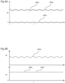
- the computer program instructions define a set of control process blocks illustrated in the flow chart of Fig. 4 .
- control process block 401 the controller 26 determines a desired, nominal, heading and speed 401 a of the robotic lawnmower 14.
- the desired heading and speed may be determined following any predetermined navigation algorithm defined by the computer program instructions in the memory 28, as well known in the art, and may also be based on further input from e.g. the boundary sensor 35 ( Fig. 3 ) and/or the GNSS receiver 42 ( Fig. 3 ).
- control process block 402 the controller 26 generates, based on the desired heading and speed, a first drive signal 402a for the first drive wheel 18a.
- control process block 403 the controller 26 generates a time-variant drive signal pattern overlay 403a.
- control process block 404 the controller 26 applies the time-variant drive signal pattern overlay 403a to the first drive signal 402a generated by control process block 402 to form a first wheel control signal 404a, which is used for operating the first wheel drive motor 24a such that the first drive wheel 18a moves in accordance with the first wheel control signal 404a. If the first drive wheel 18a does not slip, also the chassis 14a ( Fig. 2 ), and accordingly, the movement detector 33 ( Fig. 3 ) rigidly fixed thereto, moves in accordance with the first wheel control signal 404a. The resulting movement, if any, is represented by element 405 of Fig. 4 .
- control process block 406 the controller 26 receives a movement signal 406a from the movement detector 33 ( Fig. 3 ).
- the movement 405 links the first wheel control signal 404a to the movement signal 406a.
- the controller 26 analyzes the movement signal 406a to identify the time-variant drive signal pattern overlay 403a therein, and determines a slip state 407a based on the presence, if any, of the time-variant drive signal pattern overlay 403a in the movement signal 406a. If the magnitude of the time-variant drive signal pattern overlay 403a in the movement signal 406a exceeds a limit value, the controller 26 determines that the first drive wheel 18a ( Fig. 1 ) of the robotic lawnmower 14 is not slipping; if not, it determines that the first drive wheel 18a of the robotic lawnmower 14 is slipping, at least to a certain extent.
- the controller 26 may also determine an extent to which the first drive wheel 18a is slipping, i.e. whether the first drive wheel 18a slips a lot or not so much, based on the extent to which the magnitude of the time-variant drive signal pattern overlay 403a in the movement signal 406a fails to reach the limit value.
- the slip detection may be supplemented by process block 408, in which the controller 26 determines whether the robotic lawnmower 14 ( Fig. 1 ) has been lifted.
- a lift indication 408a is provided to the slip determination process block 407, and in control process block 407, the controller 26 may determine that the robotic lawnmower 14 is slipping is based on the further condition that no lift has been detected in process block 408.
- Lift may be detected in control process block 408 by, for example, determining the rotation resistance of the first drive wheel 18a, and comparing it to a reference resistance value. If the rotation resistance is lower than the reference resistance value, the first drive wheel 18a spins freely in the air, and accordingly, the robotic lawnmower 14 has been lifted; otherwise, it has not been lifted.
- the rotation resistance of the first drive wheel 18a may be represented by the drive current required for operating the first wheel drive motor 24a.
- the method may be supplemented by process block 409, in which the controller 26, in response to having determined that the first drive wheel 18a is slipping, reverses the rotation direction of the first and/or second drive wheel 18a, 18b so as to attempt to turn the robotic lawnmower 14 away from any obstacle that may have caused slipping, or drive the robotic lawnmower 14 in the reverse direction R ( Fig. 1 ).
- the time-variant drive signal pattern overlay 403a may follow a predetermined pattern, and the identification in control process block 407 may be hard-coded to to identify the predetermined pattern.
- the time-variant drive signal pattern overlay 403a may follow a pattern which is dynamically generated. Such a dynamically generated pattern may be forwarded to the control process block 407 such that the controller 26, in control process 407, may identify the time-variant drive signal pattern overlay 403a in the movement signal 406a by comparing the movement signal 406a to the time-variant drive signal pattern overlay 403a received directly from control process block 403 via the broken-line arrow.
- the diagram of Fig. 5A illustrates the respective magnitudes M of the first drive signal 402a, the time-variant drive signal pattern overlay 403a and the first wheel control signal 404a according to a first example.
- the time-variant drive signal pattern overlay 403a is a sinusoidal signal as a function of time t.
- the time-variant drive signal pattern overlay 403a has alternatingly positive and negative values, such that the average value, integrated over a large period of time t, is close to 0.
- the example illustrates a situation where the first drive signal 402a represents a constant speed of the first drive wheel 18a.
- An exemplary suitable frequency of the sinusoidal time-variant drive signal pattern overlay 403a may be, e.g., between 0,1 Hz and 100 Hz.
- the magnitude of the time-variant drive signal pattern overlay 403a is only a small fraction of the magnitude of the first drive signal 402a.
- Fig. 5B which also illustrates the second wheel control signal 404b used for operating the second wheel drive motor 24b ( Fig. 3 ).
- the example illustrates a situation where the second drive signal 402b is identical to the first drive signal 402a, i.e. the first and second drive signals 402a, 402b represent a nominal navigation along a straight line and at a constant speed. No time-variant drive signal pattern overlay is applied to the second drive signal 402b. Thereby, the second wheel control signal 404b is identical to the second drive signal 402b.
- Fig. 5C illustrates the resulting trajectory of the robotic lawnmower 14. Due to the sinusoidal character of the first wheel control signal 404a ( Fig. 5B ), the robotic lawnmower 14 follows a meandering path P by turning alternatingly to the left and to the right of an otherwise straight nominal path N. Please note that Fig. 5C exaggerates the meandering character of the path P for illustration purposes; in reality, the deviations of the path P from the nominal path N may be so small that they are not visible.
- Fig. 6 illustrates a second exemplary pattern of a time-variant signal to be used as a drive signal pattern overlay.
- the first time-variant drive signal pattern overlay 403a, to be applied to the first drive signal 402a (Fig. 4B) is identical to, and in phase with, the second time-variant drive signal pattern 403b to be applied to the second drive signal 402b (Fig. 4B).
- the speed variations of the first and second drive wheels 18a, 18b, caused by the first and second time-variant drive signal pattern overlays 403a, 403b are identical, such that the first and second time-variant drive signal pattern overlays 403a, 403b do not cause the robotic lawnmower 14 to leave its nominal path or follow a meandering path. Instead, the robotic lawnmower alternatingly accelerates and decelerates along its nominal path N ( Fig. 5C ).
- the respective magnitudes M of the first and second time-variant drive signal pattern overlays 403a, 403b follow a repetitive triangular function.
- the rotary speed of the first and second drive wheels 18a, 18b may follow a corresponding triangular function, and the movement signal 406a, which represents the acceleration a in the forward direction F ( Fig. 1 ), may alternate between positive and negative values as illustrated in Fig. 6 .
- Such acceleration variations may easily and readily be detected by e.g. the accelerometer 36.
- Fig. 7 illustrates a computer-readable storage medium, embodied as a Compact Disc 99, having stored thereon a computer program product implementing the process blocks 401-409 of Fig. 4 .
Landscapes
- Engineering & Computer Science (AREA)
- Life Sciences & Earth Sciences (AREA)
- Environmental Sciences (AREA)
- Transportation (AREA)
- Mechanical Engineering (AREA)
- Physics & Mathematics (AREA)
- Automation & Control Theory (AREA)
- Sustainable Energy (AREA)
- Sustainable Development (AREA)
- Power Engineering (AREA)
- Aviation & Aerospace Engineering (AREA)
- Radar, Positioning & Navigation (AREA)
- Remote Sensing (AREA)
- General Physics & Mathematics (AREA)
- Mathematical Physics (AREA)
- Control Of Position, Course, Altitude, Or Attitude Of Moving Bodies (AREA)
Abstract
The present invention relates to a method of detecting slip between a self-propelled robotic tool (14) and a grass surface (17), the method comprising the steps of: driving (401) on the grass surface; based on a desired heading and speed (401a) of the self-propelled robotic tool, generating (402) a first drive signal (402a) for a first drive wheel of the self-propelled robotic tool; generating (403) a time-variant drive signal pattern overlay (403a); applying (404) said time-variant drive signal pattern overlay (403a) to said first drive signal (402a) to form a first wheel control signal (404a); operating a first drive wheel based on said first wheel control signal (404a); receiving (406) a movement signal (406a) from a movement detector; and determining (407) a slip state (407a) based on an identification of said time-variant drive signal pattern overlay (403a) in said movement signal (406a).
Description
- The present invention relates to a method of detecting slip between a self-propelled robotic tool and a grass surface. The invention further relates to a self-propelled robotic tool, as well as data processing equipment, configured to carry out the method, along with a computer program product implementing the method and a computer-readable storage medium storing the computer program product.
- Self-propelled robotic tools such as robotic lawnmowers autonomously operate unattended within a work area. It may happen that such a robotic tool gets stuck at an obstacle. If the wheels keep on spinning, the grass surface may be damaged. For this and other reasons, most robotic lawnmowers are provided with sensors for detecting collisions and/or wheel slip. There are various known methods for detecting the wheel slip of a robotic lawnmower. For example,
US 2014/330496 A1 suggests that wheel slippage can be detected based on the drive current to a drive wheel falling below a certain value. - A problem with the method of
US 2014/330496 A1 is that it does not work very well in situations where the friction between grass and drive wheels is intrinsically low. This may be the case for e.g. low-weight robotic lawnmowers, for lawnmowers driving on wet grass, or if wheels having smooth or fine-patterned rolling surfaces, intended for delicate grass surfaces, are used. This can in principle be addressed by adding dead weight to the lawnmowers. However, adding weight is not a satisfactory solution, because it increases the energy consumption of the robotic lawnmower. As the robotic lawnmower market matures, there is also a trend towards less complex and less expensive robotic lawnmowers. - It is an object of the present invention to solve, or at least mitigate, parts or all of the above mentioned problems. To this end, there is provided a method of detecting slip between a self-propelled robotic tool and a grass surface, comprising: driving on the grass surface; based on a desired heading and speed of the self-propelled robotic tool, generating a first drive signal for a first drive wheel of the self-propelled robotic tool; generating a time-variant drive signal pattern overlay; applying said time-variant drive signal pattern overlay to said first drive signal to form a first wheel control signal; operating a first drive wheel based on said first wheel control signal; receiving a movement signal from a movement detector; and determining a slip state based on an identification of said time-variant drive signal pattern overlay in said movement signal. Using this method, wheel slip can be detected regardless of the slip friction between drive wheels and grass. In particular, it works well for low-weight robotic tools, and thereby permits a reduction in weight, cost and complexity of such robotic tools, as well as an ensuing reduction of power consumption. It also works well for other situations where friction between drive wheels and grass is low. The time-variant drive signal pattern overlay may, for example, be a repetitive signal such as a periodic signal of a set frequency. The identification may, for example, be made by using a band-pass filter with its pass band at the set frequency. The set frequency may be predetermined; alternatively, it may be dynamically set, and the pass band of the band pass filter may be dynamically adjusted accordingly. According to further examples, the time-variant drive signal pattern overlay may comprise consecutive velocity ramps of opposite signs, and the identification of the time-variant drive signal pattern overlay may comprise the identification of consecutive sets of accelerations and decelerations. According to still further examples, the time-variant drive signal pattern overlay may comprise a step function, and the identification may comprise the identification of a corresponding acceleration or retardation peak. In fact, the time-variant drive signal pattern overlay may have any other suitable pattern, and may be identified using any other suitable signal identification technique, such as a trained classifier trained on the specific pattern. The time-variant drive signal pattern overlay may be predetermined; alternatively, it may be generated based on a predetermined algorithm. Still alternatively, it may be void of any specific predetermined character, for example using a random function. In the latter case, the identification of the time-variant drive signal pattern overlay in said movement signal may be based on a comparison with a stored copy of the time-variant drive signal pattern overlay. The slip state may be binary, its binary values corresponding to "slip detected" and "slip not detected". Alternatively, the slip state may be represented as a probability or likelihood that the self-propelled robotic tool is slipping.
- According to embodiments, the method may further comprise: based on said desired heading and speed of the self-propelled robotic tool, generating a second drive signal for a second drive wheel of the self-propelled robotic tool; applying a time-variant drive signal pattern overlay to said second drive signal to form a second wheel control signal; and operating a second drive wheel based on said second wheel control signal. The time-variant drive signal pattern overlay applied to the second drive signal for the second drive wheel may be the same as the time-variant drive signal pattern overlay applied to the first drive signal for the first drive wheel. Alternatively, it may be different. Accordingly, the generation of a time-variant drive signal pattern overlay may comprise generating a first time-variant drive signal pattern overlay for the first drive signal and generating a second, different, time-variant drive signal pattern overlay for the second drive signal, and the determination of a slip state may be based on an identification, in said movement signal, of a first time-variant drive signal pattern overlay applied to the first drive signal and a second time-variant drive signal pattern overlay applied to the second drive signal.
- According to embodiments, the method may comprise applying the same time-variant drive signal pattern overlay to each of said first and second drive signals. Thereby, identification of the time-variant drive signal pattern overlay in the movement signal may be facilitated. According to embodiments, the time-variant drive signal pattern overlay applied to the first drive signal may be in phase with the time-variant drive signal pattern overlay applied to the second drive signal. Such a method results in time-variant deviations of the self-propelled robotic tool's speed and acceleration only. Such deviations are more difficult for a person to see, which reduces the risk that a user of the self-propelled robotic tool thinks that there is a problem with the self-propelled robotic tool's behaviour. Alternatively, the time-variant drive signal pattern overlay applied to the first drive signal may be out of phase with the time-variant drive signal pattern overlay applied to the second drive signal. This results in a change of the self-propelled robotic tool's heading. Such changes are easy to detect, which may facilitate the determination of a slip state based on an identification of the time-variant drive signal pattern overlay in the movement signal.
- According to embodiments, the time-variant drive signal pattern overlay of the first wheel control signal may be different from any time-variant drive signal pattern overlay of any second wheel control signal. Such an embodiment results in time-variant deviations of the self-propelled robotic tool's heading. According to some embodiments, different time-variant drive signal pattern overlays may be applied to different drive signals destined for different drive wheels. According to other embodiments, a time-variant drive signal pattern overlay is applied to a single drive signal, destined for a single drive wheel, only.
- According to embodiments, a determination that the self-propelled robotic tool is slipping is based on a further condition that no lift has been detected. Lift may be detected by e.g. separate lift sensors, by detecting a vertical acceleration, or by any other suitable method.
- According to embodiments, the method may further comprise: determining a drive wheel rotation resistance; comparing the drive wheel rotation resistance to a reference resistance value; and based on said comparison, determining that the self-propelled robotic tool has not been lifted. Thereby, lift events, at which the drive wheel rotation resistance is low, can easily be distinguished from slip events, at which the drive wheel rotation resistance is higher due to slipping contact with the ground. The drive wheel rotation resistance may be represented by a wheel drive motor current for turning the drive wheel. The reference resistance value may be predetermined. Alternatively, it may be dynamically set. For example, the reference resistance value may be set based on the inclination of the ground upon which the self-propelled robotic tool operates.
- According to embodiments, said time-variant drive signal pattern overlay alternates between positive and negative values. Thereby, said time-variant drive signal pattern overlay does not, over time, result in a substantial drift of the path from an intended path corresponding to said first drive signal. According to embodiments, an average value of said time-variant drive signal pattern overlay, over time, is about zero.
- According to embodiments, said time-variant drive signal pattern overlay varies with a frequency of between 0,1 Hz and 100 Hz. Such a frequency range is well adapted to the dynamics of a self-propelled robotic tool such as a robotic lawnmower, and results in a movement signal which is easy to detect. The frequency may be constant or variable.
- According to embodiments, a magnitude of the time-variant drive signal pattern overlay is less than 20% of a magnitude of the first drive signal. Thereby, the behaviour of the self-propelled robotic tool will not look erratic to an observer. The magnitude may, for example, correspond to a certain drive current level. According to further embodiments, the magnitude of the time-variant drive signal pattern overlay may be less than 10% of a magnitude of the first drive signal.
- According to embodiments, said movement detector comprises at least one of an accelerometer, a gyroscope, and a magnetometer. Preferably, the movement detector may comprise two or more different ones of the mentioned kinds of sensors. The sensors may be integrated into an inertial measurement unit, IMU.
- According to embodiments, the method may further comprise: in response to having determined that the self-propelled robotic tool is slipping, reversing a rotation direction of said first drive wheel. Thereby, the self-propelled robotic tool will reverse or turn away from any obstacle that may have caused the slip. The rotation direction of any second drive wheel may also be rotated.
- According to a second aspect, there is provided data processing equipment comprising at least one processor and memory, configured to carry out the method as defined in any of the embodiments hereinabove.
- According to a third aspect, there is provided a self-propelled robotic tool comprising: a first drive wheel; a first drive wheel motor configured to rotate said first drive wheel; a movement detector; and data processing equipment as defined hereinabove.
- According to embodiments, the self-propelled robotic tool further comprises a second drive wheel and, in addition to the first and second drive wheels, at least one further wheel configured to roll on the grass surface, wherein all of said first and second drive wheels and said at least one further wheel are carried by a single, rigid chassis. Low-weight lawnmowers are usually of the aforesaid single-chassis type, whereby all wheels are mounted to the same rigid chassis, and thereby particularly benefit from the slip detection methods defined herein.
- According to embodiments, the self-propelled robotic tool has a weight of less than 9,0 kg. According to further embodiments, the self-propelled robotic tool has a weight of less than 7,0 kg; according to still further embodiments, the self-propelled robotic tool weighs 5,5 kg or less.
- According to a fourth aspect, there is provided a computer program product comprising instructions which, when the program is executed on a processor, carries out the method as defined in any of the embodiments hereinabove.
- According to a fifth aspect, there is provided a computer-readable storage medium having stored thereon the computer program product defined hereinabove.
- It is noted that embodiments of the invention may be embodied by all possible combinations of features recited in the claims. Further, it will be appreciated that the various embodiments described for the device are all combinable with the method as defined in accordance with the second aspect of the present invention, and vice versa.
- The above, as well as additional objects, features and advantages of the present invention, will be better understood through the following illustrative and nonlimiting detailed description of preferred embodiments of the present invention, with reference to the appended drawings, where the same reference numerals will be used for similar elements, wherein:
-
Fig. 1 is a perspective view of a robotic lawnmower system comprising a charging station and a robotic lawnmower operating on a grass surface; -
Fig. 2 is a bottom view of the robotic lawnmower ofFig. 1 ; -
Fig. 3 is a block diagram of the robotic lawnmower ofFig. 1 , and illustrates various functional blocks of the robotic lawnmower; -
Fig. 4 is a flow chart illustrating control process blocks of a control process of the robotic lawnmower ofFigs 1-3 , the control process being adapted for detecting wheel slip of the robotic lawnmower; -
Fig. 5A is a diagram illustrating components of a first wheel control signal, for a first drive wheel of the robotic lawnmower ofFigs 1-3 , as a function of time; -
Fig. 5B is a diagram illustrating first and second wheel control signals, for first and second drive wheels of the robotic lawnmower ofFigs 1-3 , as a function of time; -
Fig. 5C is a top view of the robotic lawnmower ofFigs 1-3 , and illustrates the path followed by the robotic lawnmower in response to the wheel control signals ofFig. 5B ; -
Fig. 6 is a diagram illustrating components of the first and second wheel control signals for the first and second drive wheels of the robotic lawnmower ofFigs 1-3 according to a second embodiment, along with a corresponding movement detector signal resulting from movement caused by the first and second wheel control signals, as a function of time; and -
Fig. 7 is a perspective view of a compact disc holding a computer program implementing the method ofFig. 4 . - All the figures are schematic, not necessarily to scale, and generally only show parts which are necessary in order to elucidate the embodiments, wherein other parts may be omitted.
-
Fig. 1 schematically illustrates an overview of arobotic tool system 10 configured to perform a task within awork area 12 such as a garden, a park or a golf course. Therobotic tool system 10 comprises a battery-powered, self-propelled, and autonomously navigatingrobotic tool 14, along with a chargingstation 16 for charging a battery of the self-propelledrobotic tool 14. The self-propelledrobotic tool 14 is configured to drive on agrass surface 17 of thework area 12 while performing a task. As primarily described herein, therobotic tool 14 may be a robotic lawnmower, and for the sake of simplicity, it will be referred to as such in the following. However, the present disclosure may also be useful in connection with self-propelled robotic tools configured as golf ball collecting tools, agricultural machinery, mine clearance robots, or any other type of self-propelled robotic tools that are required to navigate across a grass surface to perform its task. In particular, the teachings herein may be of particular use in robotic tools configured to execute a task over an area to be treated, wherein a full or at least predetermined coverage of the area to be treated is desired. Thework area 12 may be delimited by aboundary 15 which may be physical, i.e. defined by physical obstacles or a boundary cable carrying a boundary signal, or virtual, i.e. based on positions of boundary segments in a map used by therobotic lawnmower 14 for navigating. -
Fig. 2 illustrates therobotic lawnmower 14 from below. Therobotic lawnmower 14 is provided withwheels work area 12. In the illustrated example, therobotic lawnmower 14 has twodrive wheels robotic lawnmower 14, and twonon-driven wheels drive wheels robotic lawnmower 14 across the grass surface 17 (Fig. 1 ). Therobotic lawnmower 14 mainly propels itself in a forward direction F while cutting grass, even though it may be capable of occasionally reversing in a rearward direction R, for example in response to collisions with objects. Thereby, in the illustrated example, thedrive wheels 18a-b are the rear wheels of therobotic lawnmower 14, and thenon-driven wheels 20a-b are the front wheels of therobotic lawnmower 14. Allwheels single chassis 14a, which is configured as a rigid plastic shell enclosing electronic components of therobotic lawnmower 14. Acover 14b encloses an upper portion of thechassis 14a. A robotic tool also typically comprises at least one work implement configured to perform the task on the area to be treated. In the example of therobotic lawnmower 14, the work implement is agrass cutter 22, which may be rotatable about a vertical axis. -
Fig. 3 illustrates functional blocks of therobotic lawnmower 14 seen from above. In the example ofFig. 3 , afirst drive wheel 18a is connected to a first electricwheel drive motor 24a, and asecond drive wheel 18b is connected to a second electricwheel drive motor 24b. This allows for driving the first andsecond drive wheels robotic lawnmower 14. Therobotic lawnmower 14 further comprises anelectronic controller 26. Thecontroller 26 is connected to sensors, actuators, and communication interfaces of various kinds, and may be implemented using a central processing unit, CPU, executing instructions stored on amemory 28 which may be external or internal to thecontroller 26. Needless to say, different combinations of general and application-specific integrated circuits may be used for thecontroller 26. Similarly, thememory 28 may be implemented using many different memory technologies, such as RAM, ROM etc. In general, thecontroller 26 is configured to read instructions from thememory 28 and execute these instructions, in view of different sensor signals, to control the operation of therobotic lawnmower 14. Typically, thecontroller 26 is configured to, based on the instructions, control therobotic lawnmower 14 to navigate thework area 12 and perform its task in an autonomous or semi-autonomous manner, i,e. with no, or only occasional, instructions from a human operator. Thecontroller 26 also controls the operation of acutter motor 30, which is configured to drive the grass cutter 22 (Fig. 2 ). - A
wireless transceiver 32 is connected to thecontroller 26, and allows thecontroller 26 to communicate with the charging station 16 (Fig. 1 ) or any other device, such as a remote control or a smart phone (not shown). Accordingly, thecontroller 26 and/ormemory 28 may alternatively be located in any other part of therobotic tool system 10, such as the chargingstation 16, which may autonomously direct the operation of therobotic lawnmower 14. - The
robotic lawnmower 14 further comprises amovement detector 33 comprising an inertial measurement unit, IMU, 34. TheIMU 34, which is rigidly connected to thechassis 14a (Fig. 2 ), comprises anaccelerometer 36, agyroscope 38, and amagnetometer 40. TheIMU 34 detects relative movements of therobotic lawnmower 14, and assists therobotic lawnmower 14 to keep track of its movement within thearea 12 to be mowed. In the illustrated example, therobotic lawnmower 14 also comprises a GNSS (Global Navigation Satellite System)receiver 42. The GNSS receiver is configured to receive navigation signals from navigation satellite systems such as GPS, and thereby enables absolute positioning within the work area; as such, the GNSS receiver may be seen as a part of themovement detector 34. The GNSS satellite signals may be supplemented by correction signals from one or several local beacons, or over a network, which may enable RTK (real-time kinematic) enhanced GNSS navigation. A local RTK beacon may e.g. be arranged in the charging station 16 (Fig. 1 ). - The
robotic lawnmower 14 further comprises aboundary sensor 35 configured to detect the boundary 15 (Fig. 1 ) of thework area 12. Theboundary sensor 35 may, for example, comprise an inductor configured to detect a magnetic field generated by electric current in a boundary cable. - The
controller 26 controls thewheel drive motors robotic lawnmower 14 within thework area 12 to be mowed. Thewheel drive motors controller 26 to precisely control the speed and rotation of the respectivewheel drive motors robotic lawnmower 14, as well as any turning angle of therobotic lawnmower 14 when thewheel drive motors - The
controller 26,movement detector 33,boundary sensor 35,transceiver 32,wheel drive motors cutter motor 30 are powered by abattery 44, which is typically situated between thedrive wheels drive wheels robotic lawnmower 14 is configured to navigate to the charging station 16 (Fig. 1 ) on a regular basis, for example between work sessions and/or whenever the battery charge is running low, in order to dock with the chargingstation 16 for recharging thebattery 44. The chargingstation 16 may be connected so as to receive power from the electric power grid. - The robotic lawnmower 14 (
Fig. 3 ) is configured to perform a method of detecting slip of thedrive wheels Fig. 3 ). Thecontroller 26 executes the instructions, while driving in e.g. the forward direction F on the grass surface 17 (Fig. 1 ) within thework area 12, and thereby causes therobotic lawnmower 14 to perform the method. The computer program instructions define a set of control process blocks illustrated in the flow chart ofFig. 4 . - In
control process block 401, thecontroller 26 determines a desired, nominal, heading and speed 401 a of therobotic lawnmower 14. The desired heading and speed may be determined following any predetermined navigation algorithm defined by the computer program instructions in thememory 28, as well known in the art, and may also be based on further input from e.g. the boundary sensor 35 (Fig. 3 ) and/or the GNSS receiver 42 (Fig. 3 ). - In
control process block 402, thecontroller 26 generates, based on the desired heading and speed, afirst drive signal 402a for thefirst drive wheel 18a. - In
control process block 403, thecontroller 26 generates a time-variant drivesignal pattern overlay 403a. - In
control process block 404, thecontroller 26 applies the time-variant drivesignal pattern overlay 403a to thefirst drive signal 402a generated by control process block 402 to form a firstwheel control signal 404a, which is used for operating the firstwheel drive motor 24a such that thefirst drive wheel 18a moves in accordance with the firstwheel control signal 404a. If thefirst drive wheel 18a does not slip, also thechassis 14a (Fig. 2 ), and accordingly, the movement detector 33 (Fig. 3 ) rigidly fixed thereto, moves in accordance with the firstwheel control signal 404a. The resulting movement, if any, is represented byelement 405 ofFig. 4 . - In
control process block 406, thecontroller 26 receives amovement signal 406a from the movement detector 33 (Fig. 3 ). Themovement 405 links the firstwheel control signal 404a to themovement signal 406a. - In
control process block 407, thecontroller 26 analyzes themovement signal 406a to identify the time-variant drivesignal pattern overlay 403a therein, and determines aslip state 407a based on the presence, if any, of the time-variant drivesignal pattern overlay 403a in themovement signal 406a. If the magnitude of the time-variant drivesignal pattern overlay 403a in themovement signal 406a exceeds a limit value, thecontroller 26 determines that thefirst drive wheel 18a (Fig. 1 ) of therobotic lawnmower 14 is not slipping; if not, it determines that thefirst drive wheel 18a of therobotic lawnmower 14 is slipping, at least to a certain extent. Thecontroller 26 may also determine an extent to which thefirst drive wheel 18a is slipping, i.e. whether thefirst drive wheel 18a slips a lot or not so much, based on the extent to which the magnitude of the time-variant drivesignal pattern overlay 403a in themovement signal 406a fails to reach the limit value. - Optionally, the slip detection may be supplemented by
process block 408, in which thecontroller 26 determines whether the robotic lawnmower 14 (Fig. 1 ) has been lifted. A lift indication 408a is provided to the slipdetermination process block 407, and incontrol process block 407, thecontroller 26 may determine that therobotic lawnmower 14 is slipping is based on the further condition that no lift has been detected inprocess block 408. - Lift may be detected in control process block 408 by, for example, determining the rotation resistance of the
first drive wheel 18a, and comparing it to a reference resistance value. If the rotation resistance is lower than the reference resistance value, thefirst drive wheel 18a spins freely in the air, and accordingly, therobotic lawnmower 14 has been lifted; otherwise, it has not been lifted. The rotation resistance of thefirst drive wheel 18a may be represented by the drive current required for operating the firstwheel drive motor 24a. - Optionally, the method may be supplemented by
process block 409, in which thecontroller 26, in response to having determined that thefirst drive wheel 18a is slipping, reverses the rotation direction of the first and/orsecond drive wheel robotic lawnmower 14 away from any obstacle that may have caused slipping, or drive therobotic lawnmower 14 in the reverse direction R (Fig. 1 ). - The time-variant drive
signal pattern overlay 403a may follow a predetermined pattern, and the identification in control process block 407 may be hard-coded to to identify the predetermined pattern. Alternatively, the time-variant drivesignal pattern overlay 403a may follow a pattern which is dynamically generated. Such a dynamically generated pattern may be forwarded to the control process block 407 such that thecontroller 26, incontrol process 407, may identify the time-variant drivesignal pattern overlay 403a in themovement signal 406a by comparing themovement signal 406a to the time-variant drivesignal pattern overlay 403a received directly from control process block 403 via the broken-line arrow. - The diagram of
Fig. 5A illustrates the respective magnitudes M of thefirst drive signal 402a, the time-variant drivesignal pattern overlay 403a and the firstwheel control signal 404a according to a first example. In the example, the time-variant drivesignal pattern overlay 403a is a sinusoidal signal as a function of time t. The time-variant drivesignal pattern overlay 403a has alternatingly positive and negative values, such that the average value, integrated over a large period of time t, is close to 0. The example illustrates a situation where thefirst drive signal 402a represents a constant speed of thefirst drive wheel 18a. An exemplary suitable frequency of the sinusoidal time-variant drivesignal pattern overlay 403a may be, e.g., between 0,1 Hz and 100 Hz. As illustrated, the magnitude of the time-variant drivesignal pattern overlay 403a is only a small fraction of the magnitude of thefirst drive signal 402a. - The example continues with the diagram of
Fig. 5B , which also illustrates the secondwheel control signal 404b used for operating the secondwheel drive motor 24b (Fig. 3 ). The example illustrates a situation where thesecond drive signal 402b is identical to thefirst drive signal 402a, i.e. the first andsecond drive signals second drive signal 402b. Thereby, the secondwheel control signal 404b is identical to thesecond drive signal 402b. -
Fig. 5C illustrates the resulting trajectory of therobotic lawnmower 14. Due to the sinusoidal character of the firstwheel control signal 404a (Fig. 5B ), therobotic lawnmower 14 follows a meandering path P by turning alternatingly to the left and to the right of an otherwise straight nominal path N. Please note thatFig. 5C exaggerates the meandering character of the path P for illustration purposes; in reality, the deviations of the path P from the nominal path N may be so small that they are not visible. -
Fig. 6 illustrates a second exemplary pattern of a time-variant signal to be used as a drive signal pattern overlay. In the example ofFig. 6 , the first time-variant drivesignal pattern overlay 403a, to be applied to thefirst drive signal 402a (Fig. 4B) is identical to, and in phase with, the second time-variantdrive signal pattern 403b to be applied to thesecond drive signal 402b (Fig. 4B). Thereby, the speed variations of the first andsecond drive wheels robotic lawnmower 14 to leave its nominal path or follow a meandering path. Instead, the robotic lawnmower alternatingly accelerates and decelerates along its nominal path N (Fig. 5C ). The respective magnitudes M of the first and second time-variant drive signal pattern overlays 403a, 403b follow a repetitive triangular function. Accordingly, the rotary speed of the first andsecond drive wheels movement signal 406a, which represents the acceleration a in the forward direction F (Fig. 1 ), may alternate between positive and negative values as illustrated inFig. 6 . Such acceleration variations may easily and readily be detected by e.g. theaccelerometer 36. -
Fig. 7 illustrates a computer-readable storage medium, embodied as a Compact Disc 99, having stored thereon a computer program product implementing the process blocks 401-409 ofFig. 4 . - The invention has mainly been described above with reference to a few embodiments. However, as is readily appreciated by a person skilled in the art, other embodiments than the ones disclosed above are equally possible within the scope of the invention, as defined by the appended patent claims.
- In the claims, the word "comprising" does not exclude other elements or steps, and the indefinite article "a" or "an" does not exclude a plurality.
Claims (17)
- A method of detecting slip between a self-propelled robotic tool (14) and a grass surface (17), comprising:driving on the grass surface (17);based on a desired heading and speed of the self-propelled robotic tool (14), generating a first drive signal (402a) for a first drive wheel (18a) of the self-propelled robotic tool (14);generating a time-variant drive signal pattern overlay (403a);applying said time-variant drive signal pattern overlay (403a) to said first drive signal (402a) to form a first wheel control signal (404a);operating a first drive wheel (18a) based on said first wheel control signal (404a);receiving a movement signal (406a) from a movement detector (33); anddetermining a slip state (407a) based on an identification of said time-variant drive signal pattern overlay (403a) in said movement signal (406a).
- The method according to claim 1, further comprising:based on said desired heading and speed of the self-propelled robotic tool (14), generating a second drive signal (402b) for a second drive wheel (18b) of the self-propelled robotic tool (14);applying a time-variant drive signal pattern overlay (403b) to said second drive signal (402b) to form a second wheel control signal (404b); andoperating a second drive wheel (18b) based on said second wheel control signal (404b).
- The method according to claim 2, comprising applying the same time-variant drive signal pattern overlay (403a, 403b) to each of said first and second drive signals (402a, 402b).
- The method according to claim 1 or 2, wherein the time-variant drive signal pattern overlay (403a) of the first wheel control signal (404a) is different from any time-variant drive signal pattern overlay (403b) of any second wheel control signal (404b).
- The method according to any of the preceding claims, wherein a determination that the self-propelled robotic tool (14) is slipping is based on a further condition that no lift has been detected.
- The method according to claim 5, wherein determining a slip state (407a) further comprises:determining a drive wheel rotation resistance;comparing the drive wheel rotation resistance to a reference resistance value; andbased on said comparison, determining that the self-propelled robotic tool (14) has not been lifted.
- The method according to any of the preceding claims, wherein said time-variant drive signal pattern overlay (403a) alternates between positive and negative values.
- The method according to any of the preceding claims, wherein said time-variant drive signal pattern overlay (403a) varies with a frequency of between 0,1 Hz and 100 Hz.
- The method according to any of the preceding claims, wherein a magnitude (M) of the time-variant drive signal pattern overlay (403a) is less than 20% of a magnitude (M) of the first drive signal (402a).
- The method according to any of the preceding claims, wherein said movement detector (33) comprises at least one of an accelerometer (36), a gyroscope (38), and a magnetometer (40).
- The method according to any of the preceding claims, comprising:
in response to having determined that the self-propelled robotic tool (14) is slipping, reversing a rotation direction of said first drive wheel (18a). - Data processing equipment comprising at least one processor (26) and memory (28), configured to carry out the method of any of the claims 1-11.
- A self-propelled robotic tool (14) comprising:a first drive wheel (18a);a first wheel drive motor (24a) configured to rotate said first drive wheel (18a);a movement detector (33); anddata processing equipment according to claim 12.
- The self-propelled robotic tool (14) of claim 13, further comprising a second drive wheel (18b) and, in addition to the first and second drive wheels (18a, 18b), at least one further wheel (20a, 20b) configured to roll on the grass surface (17), wherein all of said first and second drive wheels (18a, 18b) and said at least one further wheel (20a, 20b) are carried by a single, rigid chassis (14a).
- The self-propelled robotic tool (14) according to any of the claims 13-14, wherein the self-propelled robotic tool (14) has a weight of less than 9,0 kg.
- A computer program product comprising instructions which, when the program is executed on a processor (26), carries out the method according to any of the claims 1-11.
- A computer-readable storage medium (99) having stored thereon the computer program product of claim 16.
Applications Claiming Priority (1)
| Application Number | Priority Date | Filing Date | Title |
|---|---|---|---|
| SE2350577A SE547094C2 (en) | 2023-05-11 | 2023-05-11 | Detection of slip between a self-propelled robotic lawnmower and a grass surface |
Publications (1)
| Publication Number | Publication Date |
|---|---|
| EP4461114A1 true EP4461114A1 (en) | 2024-11-13 |
Family
ID=90362244
Family Applications (1)
| Application Number | Title | Priority Date | Filing Date |
|---|---|---|---|
| EP24161698.6A Pending EP4461114A1 (en) | 2023-05-11 | 2024-03-06 | Detection of slip between a self-propelled robotic tool and a grass surface |
Country Status (3)
| Country | Link |
|---|---|
| US (1) | US20240377845A1 (en) |
| EP (1) | EP4461114A1 (en) |
| SE (1) | SE547094C2 (en) |
Families Citing this family (1)
| Publication number | Priority date | Publication date | Assignee | Title |
|---|---|---|---|---|
| USD1110371S1 (en) * | 2023-07-05 | 2026-01-27 | Nanjing Chervon Industry Co., Ltd. | Robotic lawn mower |
Citations (5)
| Publication number | Priority date | Publication date | Assignee | Title |
|---|---|---|---|---|
| US20080154429A1 (en) * | 2006-12-21 | 2008-06-26 | Samsung Electronics Co., Ltd. | Apparatus, method, and medium for distinguishing the movement state of mobile robot |
| US20090157227A1 (en) * | 2007-12-14 | 2009-06-18 | Samsung Electronics Co., Ltd. | Apparatus, method, and medium for sensing slip in mobile robot |
| US20140330496A1 (en) | 2013-02-28 | 2014-11-06 | Austin Crouse | Trainable robotic apparatus, system and method |
| EP3695700A1 (en) * | 2019-02-14 | 2020-08-19 | Stiga S.P.A. | Robotic vehicle for movable operation in a work area |
| US20210289695A1 (en) * | 2017-04-18 | 2021-09-23 | Husqvarna Ab | Method for Detecting Lifting of a Self-Propelled Tool from the Ground |
Family Cites Families (8)
| Publication number | Priority date | Publication date | Assignee | Title |
|---|---|---|---|---|
| GB2552331B (en) * | 2016-07-18 | 2020-02-05 | F Robotics Acquisitions Ltd | Improvements relating to robotic lawnmowers |
| US11097736B2 (en) * | 2017-02-28 | 2021-08-24 | Clearpath Robotics Inc. | Systems and methods for traction detection and control in a self-driving vehicle |
| JP6997293B2 (en) * | 2018-03-30 | 2022-01-17 | 本田技研工業株式会社 | Autonomous traveling work equipment and control system |
| EP4218390A1 (en) * | 2018-05-25 | 2023-08-02 | The Toro Company | Autonomous grounds maintenance machines with path planning for trap and obstacle avoidance |
| SE542445C2 (en) * | 2018-06-07 | 2020-05-05 | Husqvarna Ab | Articulated self-propelled robotic tool with slip detecting arrangement |
| SE544055C2 (en) * | 2018-06-26 | 2021-11-23 | Husqvarna Ab | A method for collision detection in a self-propelled robotic tool and a self-propelled robotic tool |
| AU2018438158B2 (en) * | 2018-08-28 | 2024-05-30 | Techtronic Cordless Gp | An autonomous lawn mower and a system for navigating thereof |
| US12151922B2 (en) * | 2021-06-22 | 2024-11-26 | Symbotic Llc | Autonomous transport vehicle with synergistic vehicle dynamic response |
-
2023
- 2023-05-11 SE SE2350577A patent/SE547094C2/en unknown
-
2024
- 2024-03-06 EP EP24161698.6A patent/EP4461114A1/en active Pending
- 2024-05-10 US US18/661,114 patent/US20240377845A1/en active Pending
Patent Citations (5)
| Publication number | Priority date | Publication date | Assignee | Title |
|---|---|---|---|---|
| US20080154429A1 (en) * | 2006-12-21 | 2008-06-26 | Samsung Electronics Co., Ltd. | Apparatus, method, and medium for distinguishing the movement state of mobile robot |
| US20090157227A1 (en) * | 2007-12-14 | 2009-06-18 | Samsung Electronics Co., Ltd. | Apparatus, method, and medium for sensing slip in mobile robot |
| US20140330496A1 (en) | 2013-02-28 | 2014-11-06 | Austin Crouse | Trainable robotic apparatus, system and method |
| US20210289695A1 (en) * | 2017-04-18 | 2021-09-23 | Husqvarna Ab | Method for Detecting Lifting of a Self-Propelled Tool from the Ground |
| EP3695700A1 (en) * | 2019-02-14 | 2020-08-19 | Stiga S.P.A. | Robotic vehicle for movable operation in a work area |
Also Published As
| Publication number | Publication date |
|---|---|
| SE2350577A1 (en) | 2024-11-12 |
| SE547094C2 (en) | 2025-04-22 |
| US20240377845A1 (en) | 2024-11-14 |
Similar Documents
| Publication | Publication Date | Title |
|---|---|---|
| US12268121B2 (en) | Autonomous grounds maintenance machines with path planning for trap and obstacle avoidance | |
| AU2024220020B2 (en) | Autonomous machine navigation and training using vision system | |
| EP4104029B1 (en) | Autonomous machine navigation with object detection and 3d point cloud | |
| EP3887226B1 (en) | Differential traction drive with steering axis coordination system and method | |
| EP4461114A1 (en) | Detection of slip between a self-propelled robotic tool and a grass surface | |
| EP3915352A1 (en) | Improved control signal sensing for a robotic work tool | |
| JP2019216670A (en) | Work vehicle | |
| EP4398202B1 (en) | An autonomous ground maintenance machine with a vision system for navigating and a method for autonomous machine navigation | |
| US20200398850A1 (en) | Systems and methods for traction detection and control in a self-driving vehicle | |
| Ha et al. | Indoor navigation of an inverse pendulum type autonomous mobile robot with adaptive stabilization control system | |
| EP4666145A1 (en) | Image notification for autonomous grounds maintenance machines | |
| EP4659558A1 (en) | Control method for autonomous operation device, and autonomous operation device | |
| WO2023121528A1 (en) | Improved navigation for a robotic work tool system |
Legal Events
| Date | Code | Title | Description |
|---|---|---|---|
| PUAI | Public reference made under article 153(3) epc to a published international application that has entered the european phase |
Free format text: ORIGINAL CODE: 0009012 |
|
| STAA | Information on the status of an ep patent application or granted ep patent |
Free format text: STATUS: REQUEST FOR EXAMINATION WAS MADE |
|
| 17P | Request for examination filed |
Effective date: 20240306 |
|
| AK | Designated contracting states |
Kind code of ref document: A1 Designated state(s): AL AT BE BG CH CY CZ DE DK EE ES FI FR GB GR HR HU IE IS IT LI LT LU LV MC ME MK MT NL NO PL PT RO RS SE SI SK SM TR |