EP4459886A2 - Reconfigurable intelligent surface architecture with rfid array - Google Patents
Reconfigurable intelligent surface architecture with rfid array Download PDFInfo
- Publication number
- EP4459886A2 EP4459886A2 EP24167640.2A EP24167640A EP4459886A2 EP 4459886 A2 EP4459886 A2 EP 4459886A2 EP 24167640 A EP24167640 A EP 24167640A EP 4459886 A2 EP4459886 A2 EP 4459886A2
- Authority
- EP
- European Patent Office
- Prior art keywords
- ris
- rfid
- signal
- rfid chip
- elements
- Prior art date
- Legal status (The legal status is an assumption and is not a legal conclusion. Google has not performed a legal analysis and makes no representation as to the accuracy of the status listed.)
- Pending
Links
Images



Classifications
-
- H—ELECTRICITY
- H04—ELECTRIC COMMUNICATION TECHNIQUE
- H04B—TRANSMISSION
- H04B7/00—Radio transmission systems, i.e. using radiation field
- H04B7/02—Diversity systems; Multi-antenna system, i.e. transmission or reception using multiple antennas
- H04B7/04—Diversity systems; Multi-antenna system, i.e. transmission or reception using multiple antennas using two or more spaced independent antennas
- H04B7/04013—Intelligent reflective surfaces
-
- H—ELECTRICITY
- H01—ELECTRIC ELEMENTS
- H01Q—ANTENNAS, i.e. RADIO AERIALS
- H01Q1/00—Details of, or arrangements associated with, antennas
- H01Q1/12—Supports; Mounting means
- H01Q1/22—Supports; Mounting means by structural association with other equipment or articles
- H01Q1/2291—Supports; Mounting means by structural association with other equipment or articles used in Bluetooth® or Wi-Fi® devices of Wireless Local Area Networks [WLAN]
-
- H—ELECTRICITY
- H01—ELECTRIC ELEMENTS
- H01Q—ANTENNAS, i.e. RADIO AERIALS
- H01Q15/00—Devices for reflection, refraction, diffraction or polarisation of waves radiated from an antenna, e.g. quasi-optical devices
- H01Q15/14—Reflecting surfaces; Equivalent structures
- H01Q15/148—Reflecting surfaces; Equivalent structures with means for varying the reflecting properties
-
- H—ELECTRICITY
- H01—ELECTRIC ELEMENTS
- H01Q—ANTENNAS, i.e. RADIO AERIALS
- H01Q3/00—Arrangements for changing or varying the orientation or the shape of the directional pattern of the waves radiated from an antenna or antenna system
- H01Q3/26—Arrangements for changing or varying the orientation or the shape of the directional pattern of the waves radiated from an antenna or antenna system varying the relative phase or relative amplitude of energisation between two or more active radiating elements; varying the distribution of energy across a radiating aperture
- H01Q3/30—Arrangements for changing or varying the orientation or the shape of the directional pattern of the waves radiated from an antenna or antenna system varying the relative phase or relative amplitude of energisation between two or more active radiating elements; varying the distribution of energy across a radiating aperture varying the relative phase between the radiating elements of an array
- H01Q3/34—Arrangements for changing or varying the orientation or the shape of the directional pattern of the waves radiated from an antenna or antenna system varying the relative phase or relative amplitude of energisation between two or more active radiating elements; varying the distribution of energy across a radiating aperture varying the relative phase between the radiating elements of an array by electrical means
-
- H—ELECTRICITY
- H01—ELECTRIC ELEMENTS
- H01Q—ANTENNAS, i.e. RADIO AERIALS
- H01Q3/00—Arrangements for changing or varying the orientation or the shape of the directional pattern of the waves radiated from an antenna or antenna system
- H01Q3/44—Arrangements for changing or varying the orientation or the shape of the directional pattern of the waves radiated from an antenna or antenna system varying the electric or magnetic characteristics of reflecting, refracting, or diffracting devices associated with the radiating element
- H01Q3/46—Active lenses or reflecting arrays
-
- H—ELECTRICITY
- H04—ELECTRIC COMMUNICATION TECHNIQUE
- H04B—TRANSMISSION
- H04B5/00—Near-field transmission systems, e.g. inductive or capacitive transmission systems
- H04B5/70—Near-field transmission systems, e.g. inductive or capacitive transmission systems specially adapted for specific purposes
- H04B5/79—Near-field transmission systems, e.g. inductive or capacitive transmission systems specially adapted for specific purposes for data transfer in combination with power transfer
Definitions
- Various exemplary embodiments disclosed herein relate to a scalable reconfigurable intelligent surface architecture with RFID array.
- Range or coverage extension is of common interest for wireless communications.
- obstacles may limit the effectiveness of Wi-Fi communication.
- Devices using Wi-Fi communication have greatly increased including for example, surveillance cameras, drone control/camera, mobile devices, computers, internet-of things (IoT), smart home devices, etc.
- IoT internet-of things
- Providing Wi-Fi coverage for a large house or other facility including outdoor, backyard, and driveway coverage is challenging.
- RIS reconfigurable intelligent surface
- a reconfigurable intelligent surface including: a plurality of RIS elements including: a radio frequency identification (RFID) chip configured to power the RIS element; a RFID antenna connected to the RFID chip; a RIS variable impedance controlled by the RFID chip; and a RIS antenna connected to the RIS variable impedance, wherein the plurality of RIS elements is configured to produce a reflection beam.
- RFID radio frequency identification
- the RFID chip is configured to receive a RFID signal that includes information to steer the reflection beam.
- the reflection beam is steered by setting an impedance value of the RIS variable impedance based upon the information to steer the reflection beam.
- the RFID chip includes a lookup table of impedance values versus angle.
- the RFID chip includes a microcontroller unit (MCU) configured to control an impedance value of the RIS variable impedance.
- MCU microcontroller unit
- a signal reflected by the plurality of RIS elements is a Wi-Fi signal.
- the plurality of RIS elements are divided into a plurality of sections, wherein each section of RIS elements is independently controllable to produce multiple different RIS reflection beams.
- a reconfigurable intelligent surface including: a plurality of groups of RIS elements wherein each group includes: a first RIS element including: a radio frequency identification (RFID) chip configured to power the RIS element; a RFID antenna connected to the RFID chip; a first RIS variable impedance controlled by the RFID chip; and a first RIS antenna connected to the RIS variable impedance; a plurality of second RIS elements each RIS element including: a second RIS variable impedance controlled by the RFID chip; and a second RIS antenna connected to the RIS variable impedance; and a connection network connecting the first RIS element to each of the plurality of second RIS elements, wherein the plurality of groups of RIS elements are configured to produce a reflection beam.
- RFID radio frequency identification
- the RFID chip is configured to receive a RFID signal that includes information to steer the reflection beam.
- the reflection beam is steered by setting an impedance value of the first RIS variable impedance and second RIS variable impedance based upon the information to steer the reflection beam.
- the RFID chip includes a lookup table of impedance values versus angle.
- the RFID chip includes a microcontroller unit (MCU) configured to control an impedance value of the first RIS variable impedance and second RIS variable impedance.
- MCU microcontroller unit
- a signal reflected by the plurality of RIS elements is a Wi-Fi signal.
- the plurality of groups of RIS elements are divided into a plurality of sections, wherein each section of groups of RIS elements is independently controllable to produce multiple different RIS reflection beams.
- a method of steering a reconfigurable intelligent surface (RIS) beam of a RIS including: sending by a transmitter a sequence of unsteered sounding packets towards the RIS; setting a phased array setting of the RIS to different values from a RIS codebook for each of the sequence of sounding packets by sending a first radio frequency identification (RFID) signal to an RFID chip in the RIS; receiving information regarding the signal received by a receiver via the RIS for each of the sounding packets; selecting a phase codebook entry based upon the information regarding the signal received by a receiver; and sending a second RFID signal to the RFID chip with the selected phase codebook entry to steer the RIS beam.
- RFID radio frequency identification
- the sounding packets are Wi-Fi null data packets.
- the received information regarding the signal received by a receiver is a channel quality indicator.
- the received information regarding the signal received by a receiver is a receive signal strength indicator.
- Various embodiments are described, further including, for each of the settings in a digital codebook for the transmitter repeating the steps of: sending by a transmitter a sequence of unsteered sounding packets towards the RIS; setting phased array setting of the RIS to different values from a RIS codebook for each of the sequence of sounding packets by sending a first radio frequency identification (RFID) signal to an RFID chip in the RIS; and receiving information regarding the signal received by a receiver via the RIS for each of the sounding packets, selecting a digital codebook entry based upon the information regarding the signal received by the receiver.
- RFID radio frequency identification
- the sounding packets are Wi-Fi null data packets; and the received information regarding the signal received by a receiver is one of a channel quality indicator and a receive signal strength indicator.
- a reconfigurable intelligent surface is a programmable surface structure that may be used to control the reflection of electromagnetic (EM) waves by changing the electric and magnetic properties of the surface. These surfaces may be strategically placed in the radio channel between a transmitter and receiver to control the way the signal reflects off a surface in its propagation path. Reconfigurable intelligent surfaces may be used to steer signals to the receiver resulting in better reception or link quality.
- EM electromagnetic
- the radio channel In conventional wireless systems, the radio channel is seen as an uncontrollable entity that usually distorts transmitted signals.
- the transmitted signals usually interact with a wide range of surfaces in their propagation path and reflect off them in random directions resulting in random constructive and destructive interference.
- a RIS provides a way to control the surfaces found in radio channels by directing them in a specific direction to improve the reliability and energy efficiency of wireless systems. This can increase the range of a wireless system and direct signals to hard-to-reach places.
- An antenna array may be used to implement a RIS to control the characteristics of signals (e.g., reflection, refraction, absorption, focusing and polarization).
- scalable RIS with an RFID array is proposed in this disclosure.
- on-or-off only passive antenna switching such as Pin-diodes or external switches, are used for backscattering in the RIS antenna array while a centralized controller with massive distributed control routing is required to control each element of the RIS.
- Both on-or-off only passive switching antennas and the centralized controller limits the scaling of the size of the RIS, and it eventually reduces the benefit of the RIS.
- This RIS architecture with RFID array proposed herein provides a distributed controlling scheme that is self-powered from wireless power harvesting and implements fine antenna impedance modulation. These improvements enable a scalable RIS architecture to further improve the range and throughput of the wireless communication system such as Wi-Fi, BlueTooth (BT), ultra-wideband (UWB), etc...
- a Wi-Fi system will be used to describe the proposed scalable RIS, but the scalable RIS disclosed herein may be applied to other types of wireless communication systems.
- Wi-Fi systems sometimes are unable to provide the wireless coverage a user needs.
- Various solutions include using mesh routers and a repeater or extender.
- Mesh routers are multi-hop communication systems that may induce high latency and reduced network throughput. Further a dual-chip/dual-radio design may be needed in a mesh access point (AP) that increases cost, complexity, and power consumption.
- AP mesh access point
- the repeater or extender solution has similar challenges as the mesh system. Accordingly, another solution to address these challenges may include the use of RIS.
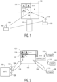
- FIG. 1 illustrates the use of RIS to improve communication between an AP and a user.
- An AP 102 is in communication with a user STA 108.
- the obstacle 112 is in the line-of-sight between the AP 102 and user STA 108, and the obstacle 112 greatly reduces the signal received by the user STA 108 from the AP 102.
- a RIS 106 may be used to improve the communication between the AP 102 and user STA 108.
- the AP antenna 104 emits a signal that propagates towards the RIS 106.
- the RIS 106 may be configured to form a reflection beam towards the user antenna 110. This may be done by setting the phase on the various RIS elements 114 to form a beam in the direction of the user antenna 110.
- the RIS 106 may be used in other applications as well including, for example, range extension, filling in dead spots, etc.
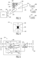
- FIG. 2 illustrates the use of a RIS in more detail.
- the AP 102 may include a plurality of AP antennas 104 that allow for the formation of a steerable Wi-Fi beam 116.
- the AP 102 may form and steer the Wi-Fi beam 116 towards the RIS 106.
- the AP 102 may communicate with a plurality of user STAs 108.
- a controller 124 may control the RIS 106 to form a RIS beam 118 that is pointed at one of the plurality of users STA 108.
- the controller 124 has a control connection with each of the RIS elements 114 in the RIS 106.
- the controller 124 may send a control signal that indicates the phase status of each of the RIS elements 114 in order to form and steer the RIS beam 118 towards the desired user STA 108. Further, controller 124 may provide power to the RIS elements 114.
- the RIS 106 has a number of problems.
- the RIS 106 requires MXN control wires that limits the size of the RIS due to the complexity of the routing the control signals which means that implementing a large array size may be difficult.
- An external battery or other power source is required to power up the controller/array.
- An external signal is required to control the controller either using a wired or wireless connection.
- the impedance of each antenna is either on or off by using a RF-switch or diode. It is difficult to reconfigure each RIS element antenna impedance Z to a desired value. Further, this approach does not easily allow for processing or manipulation of the incident RF-Signal in each antenna.
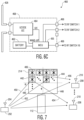
- FIG. 3 illustrates an embodiment of a RIS using an RFID chip.
- FIG. 3 illustrates an AP 202 communicating to user STAs 208 using a RIS 206.
- the AP 202 uses AP antennas 204 to form Wi-Fi beam 216 pointed at the RIS 206.
- the RIS reflects the signal from the AP 202 via the Wi-Fi beam 216 towards one of the user STAs 208 by forming and steering a RIS beam 218.
- the RIS 206 includes a plurality of RIS elements 214.
- the RIS elements 214 include an RFID chip 226.
- FIG. 4 illustrates an embodiment of the RIS element 214.
- the RIS element 214 includes a RIS element antenna 222, RFID chip 226, and a RFID antenna 228.
- the RFID chip 226 includes a RFID antenna variable impedance 232, rectifier 234, envelope detector 236, and microcontroller unit (MCU) 238.
- the RFID chip 226 is connected to the RFID antenna 228.
- the RFID antenna 228 receives an RFID signal that provides data and power to the RFID chip 226.
- a RFID antenna variable impedance 232 is set to create a resonate circuit with the RFID antenna 228 to maximize power harvesting. Then the input signal is fed to the rectifier 234 that rectifies the input signal and produces power. This power may then be applied to the envelope detector 236 and MCU 238 to turn on the envelope detector 236 and MCU 238.
- the envelope detector 236 detects the envelope of the received RFID signal where the envelope of the RFID signal carries modulated information.
- the envelope detector 236 produces a data stream carried by the RFID signal to the MCU 238.
- the received RFID information may include information regarding the direction that the RFID chip 226 should form the RIS beam 218. This can then be used to control a Wi-Fi antenna variable impedance 230 to set an impedance value that will aid in steering and forming the RIS beam 218.
- the RIS 206 first receives an RFID signal that is used to set the value for the Wi-Fi antenna variable impedance 230. Once the impedance value for the Wi-Fi antenna variable impedance 230 is set, then the AP 202 may send Wi-Fi signals that will be reflected off of the RIS 206 towards a desired user STA 208.
- a battery may be used to power the MCU 238 and the Wi-Fi antenna variable impedance 230.
- the MCU 238 may remain in a sleep mode with very low power consumption, and the MCU 238 may then wake up only when an RFID signal is received including a new configuration command for the RIS.
- the RIS element antenna 222 may be a wideband antenna that covers the frequency range of the signal to be reflected. For Wi-Fi this may be from 2.4 GHz to 7GHz. For other communication protocols the bandwidth would be set to accommodate the frequencies used. In this example a standard 900MHz RFID signal may be used. Other transmission frequencies may be used for the RFID signal based upon the power harvesting needs and the available transmit signals.
- the RFID chip 226 may use a lookup table that maps an angle of the RIS beam 218 to a specific impedance value that may be produced by the Wi-Fi antenna variable impedance 230.
- Table 1 below illustrates such a lookup table for an angular resolution of 45°.
- Table 1 Angle Z_Ant Wi-Fi ( ⁇ ) 0 150 45 69.1+65.1i 90 30 + 40.0i 135 19.16+18.06i 180 16.67+0i 225 19.16-18.0651i 270 30-40i 315 69.1-65i
- three-bit values may be used to select among the eight different impedance values. While 45° increments are shown for Table 1, larger or smaller increments may be selected as well.
- the lookup table becomes a phase codebook that is used to control the direction of the RIS beam 218.
- the RIS 206 overcomes the problems associated with the RIS 106 of FIG. 1 .
- the need for complicated wired connections to each RIS element 114 has been removed by having the RFID chip 226 provide the control information to the RIS element 214. This may be done wirelessly using existing RFID technology. Further, a separate power supply is not needed to configure the RIS 206 because the RFID chip 226 harvests power from the RFID signal to power the RIS element 214 and to set the needed impedance value for form and steer the RIS beam 218.
- the RIS 206 may be scaled to be larger and to include larger numbers of RIS elements 214. A larger RIS 206 improves the gain of the RIS beam 218 as well as allowing for a narrower RIS beam 218.
- FIG. 6A illustrates a second embodiment of a RIS using a RFID chip.
- the RIS 306 two different types of RIS elements may be used and combined to form NxN groups.
- one RIS element 214 may include a RFID chip 226.
- the remaining NxN-1 RIS elements 114 do not include an RFID chip 226 or the RFID antenna 228.
- the RFID chip 226 is then connected to Wi-Fi antenna variable impedances 230 in the other NxN-1 RIS elements 114, and the RFID chip 226 controls the impedance of the Wi-Fi antenna variable impedances 230. This may be accomplished using RFID connections 340.
- the RFID connections 340 form a connection network.
- the NxN groups could instead be NxM groups.
- the RIS 306 is illustrated as having RIS elements that are aligned in a grid, but they may be arranged in other ways as well. For example, the lines of the grid may be offset from one another. Also, the RIS elements without a RFID chip 226 may be arranged around the RIS element with a RFID chip 226 in a hexagonal or diamond shape. In another embodiment, the group of RIS elements may include two or more RIS elements with a RFID chip.
- FIG. 6B illustrates a third embodiment of a RIS using an RFID chip.
- FIG. 6C illustrates another embodiment of a RIS element found in FIG. 6B .
- the RIS element 460 in FIG. 6B is larger than the RIS element 114. This allows for a larger RFID antenna 428 which improves energy harvesting and the reliability of the communication link to the RFID chip 468.
- the RFID chip 468 includes a UCODE I2C circuit 464, battery 462, and MCU 438.
- the UCODE I2C circuit 464 receives the signal received by the RFID antenna 428 and provides it to the MCU and also may harvest power.
- the MCU 438 operates like the microcontroller unit MCU 238 described above.
- the battery 462 provides power or additional power to power the RFID chip 468.
- the MCU 438 determines the control signal for each of the associated RIS elements 114 and is connected to RF switch connector 466 to provide control signal to each of the various RIS elements 114.
- FIG. 7 illustrates a fourth embodiment of a RIS using a RFID chip.
- the RIS 306 may be divided into four sections 442, 444, 446, and 448. Each of these sections may be independently controlled to form multiple independent RIS reflection beams.
- the RFID signal may include an angle to be used by each RIS element 214 associated with each section used to form and steer a RIS beam.
- MIMO multi-input multi-output
- the AP 202 produces a first MIMO beam 450 for a first user STA 208 and a second MIMO beam 452 for a second user STA 208.
- the first MIMO beam 450 is reflected by the first section 442 to produce first RIS beam 454 that is pointed at the first user STA 208.
- the second MIMO beam 452 is reflected by the second section 444 to produce second RIS beam 456 that is pointed at the second user STA 208.
- the third section 446 may be used in conjunction with the first section 442 to reflect the first MIMO beam 450 and to form first RIS beam 454.
- the fourth section 448 may be used in conjunction with the second section 444 to reflect the second MIMO beam 452 and to form second RIS beam 456. This means that the RIS 406 may be used to improve the function of AP 202 that is using MIMO operation.
- the RIS array may steer the incoming signal to form a narrow beam to the user STA or area (i.e., to cover a dead zone) by changing the phase of each RIS reflected signal.
- FIG. 8 illustrates an embodiment of a first RIS beam steering algorithm 800.
- the RIS phased antenna array steering phase is trained/optimized for a specific STA/location.
- the optimal RIS phase array configuration is obtained by looping through the predefined RIS phase codebook and comparing the corresponding signal or channel quality for each configuration.
- the RIS phase codebook includes a set of predefined phase setting of each RIS element.
- the beam steering algorithm 800 starts at 802.
- the first RIS beam steering algorithm 800 sends a RFID signal to the RFID chip to set the RIS array to the next phase configuration 804 ("Send a RFID signal to the RFID chip to set the RIS array to the next phase array configuration and from a RIS codebook") .
- the RFID signal indicates the impedance of the Wi-Fi antenna variable impedance 230 at 806 ("transmit one or more unsteered sounding null data packets"). Then the Wi-Fi Tx transmits one or more unsteered sounding Null Data Packets (NDP) to the receiver 806.
- the receiver computes the received Channel Quality Indicator (CQI) or the Receive Signal Strength Indicator (RSSI) for the corresponding RIS phase array setting 808 ("receive each of the sounding packets by a receiver via the RIS and evaluate the signal or channel quality") and feed back to the Wi-Fi TX at the end of each NDP or the sequence of NDPs at 810(sender the signal or channel quality information back to the transmitter by the receiver").
- CQI Channel Quality Indicator
- RSSI Receive Signal Strength Indicator
- the first RIS beam steering algorithm 800 determines if the current RIS phase configuration is the last one in the RIS codebook 812 ("Is this the last RIS phase configuration in the RIS codebook"), and if not loops back to step 804 to loop through all or partial entries in the RIS phase array, and the Wi-Fi TX collects all the CQI/RSSI information.
- the Wi-Fi TX selects the optimal phase array setting with the best CQI/RSSI 814 ("select the optimal RIS phase configuration based on the feedback information") and sends the choice to the RIS array via the RFID chip 816 ("sending a RFID signal to the RFID chip to configure the RIS to the selected phase array configuration").
- the beam steering algorithm 800 ends at 818.
- the Wi-Fi TX may periodically initiate a RIS steering training process to ensure codebook choice is up to date.
- the TX may perform periodic iterations of the RIS beam steering algorithm based on the trained effective optimal Tx-RIS-Rx channel at 812. Regular Wi-Fi sounding and MIMO beamforming may be performed with the optimal RIS array to steer the data PPDU.
- FIG. 9 illustrates a second embodiment of a RIS beam steering algorithm 900.
- the training in the second algorithm is done in two loops to jointly optimize the Wi-Fi digital beamforming and the RIS array phase setting.
- the Wi-Fi TX predefines a digital steering codebook that is used to steer the digital signal to the receiver.
- the codebook can be chosen based on disturbances from the optimal steering matrix obtained based on the default RIS phase array setting. For each setting in the digital steering codebook, a RIS training is performed as described by the first beam steering algorithm.
- step 904 select the next entry in a digital steering codebook at the Wi-Fi transmitter
- the next entry in the digital steering codebook is selected.
- step 916 is this the last digital steering codebook entry
- the beam steering algorithm 900 determines if the end of the digital steering codebook has been reached.
- the Wi-Fi Tx sends a sequence of steered sounding NDPs to the destination STA 806, and the RIS runs through the codebook sequence correspondingly 804-812.
- the destination STA feeds back the CQI/RSSI 810.
- the RIS beam steering algorithm 900 selects and records the optimal RIS setting and CQI/RSSI for each digital steering codebook entry 914 ("select and record the optimal RIS phase configuration and channel or signal quality indicator based on the feedback information for the corresponding digital steering configuration"). After all information is collected, the Wi-Fi Tx will choose the combined optimal digital beamforming setting and RIS phase array setting in the codebook with the best CQI/RSSI during operation to use to steer the RIS beam 218 at 918 ("select the optimal digital steering setting configuration and the corresponding optimal RIS phase array configuration").
- the RIS beam steering algorithm 900 then configures the Wi-Fi transmitter with the optimal digital setting and sends a RFID signal to the RFID chip to configure the RIS to the selected phase array configuration 920 ("configure the Wi-Fi transmitter with the optimal digital setting and sending a RFID signal to the RFID chip to configure the RIS to the selected phase array configuration").
- the beam steering algorithm 900 ends at 922.
- ком ⁇ онент is intended to be broadly construed as hardware, firmware, and/or a combination of hardware and software.
- a processor is implemented in hardware, firmware, and/or a combination of hardware and software.
- satisfying a threshold may, depending on the context, refer to a value being greater than the threshold, greater than or equal to the threshold, less than the threshold, less than or equal to the threshold, equal to the threshold, not equal to the threshold, and/or the like. It will be apparent that systems and/or methods described herein may be implemented in different forms of hardware, firmware, and/or a combination of hardware and software. The actual specialized control hardware or software code used to implement these systems and/or methods is not limiting of the aspects. Thus, the operation and behavior of the systems and/or methods were described herein without reference to specific software code-it being understood that software and hardware can be designed to implement the systems and/or methods based, at least in part, on the description herein.
- non-transitory machine-readable storage medium will be understood to exclude a transitory propagation signal but to include all forms of volatile and nonvolatile memory.
- processor When software is implemented on a processor, the combination of software and processor becomes a specific dedicated machine.
- "at least one of: a, b, or c” is intended to cover a, b, c, a-b, a-c, b-c, and a-b-c, as well as any combination with multiples of the same element (e.g., a-a, a-a-a, a-a-b, a-a-c, a-b-b, a-c-c, b-b, b-b-b, b-b-c, c-c, and c-c-c or any other ordering of a, b, and c).
Landscapes
- Engineering & Computer Science (AREA)
- Computer Networks & Wireless Communication (AREA)
- Signal Processing (AREA)
- Physics & Mathematics (AREA)
- Electromagnetism (AREA)
- Radio Transmission System (AREA)
- Variable-Direction Aerials And Aerial Arrays (AREA)
Abstract
Description
- Various exemplary embodiments disclosed herein relate to a scalable reconfigurable intelligent surface architecture with RFID array.
- Range or coverage extension is of common interest for wireless communications. For example, for Wi-Fi communication, obstacles may limit the effectiveness of Wi-Fi communication. Devices using Wi-Fi communication have greatly increased including for example, surveillance cameras, drone control/camera, mobile devices, computers, internet-of things (IoT), smart home devices, etc. Providing Wi-Fi coverage for a large house or other facility including outdoor, backyard, and driveway coverage is challenging.
- A summary of various exemplary embodiments is presented below.
- Various embodiments relate to a reconfigurable intelligent surface (RIS), including: a plurality of RIS elements including: a radio frequency identification (RFID) chip configured to power the RIS element; a RFID antenna connected to the RFID chip; a RIS variable impedance controlled by the RFID chip; and a RIS antenna connected to the RIS variable impedance, wherein the plurality of RIS elements is configured to produce a reflection beam.
- Various embodiments are described, wherein the RFID chip is configured to receive a RFID signal that includes information to steer the reflection beam.
- Various embodiments are described, wherein the reflection beam is steered by setting an impedance value of the RIS variable impedance based upon the information to steer the reflection beam.
- Various embodiments are described, wherein the RFID chip includes a lookup table of impedance values versus angle.
- Various embodiments are described, wherein the RFID chip includes a microcontroller unit (MCU) configured to control an impedance value of the RIS variable impedance.
- Various embodiments are described, wherein a signal reflected by the plurality of RIS elements is a Wi-Fi signal.
- Various embodiments are described, wherein the plurality of RIS elements are divided into a plurality of sections, wherein each section of RIS elements is independently controllable to produce multiple different RIS reflection beams.
- Further various embodiments relate to a reconfigurable intelligent surface (RIS), including: a plurality of groups of RIS elements wherein each group includes: a first RIS element including: a radio frequency identification (RFID) chip configured to power the RIS element; a RFID antenna connected to the RFID chip; a first RIS variable impedance controlled by the RFID chip; and a first RIS antenna connected to the RIS variable impedance; a plurality of second RIS elements each RIS element including: a second RIS variable impedance controlled by the RFID chip; and a second RIS antenna connected to the RIS variable impedance; and a connection network connecting the first RIS element to each of the plurality of second RIS elements, wherein the plurality of groups of RIS elements are configured to produce a reflection beam.
- Various embodiments are described, wherein the RFID chip is configured to receive a RFID signal that includes information to steer the reflection beam.
- Various embodiments are described, wherein the reflection beam is steered by setting an impedance value of the first RIS variable impedance and second RIS variable impedance based upon the information to steer the reflection beam.
- Various embodiments are described, wherein the RFID chip includes a lookup table of impedance values versus angle.
- Various embodiments are described, wherein the RFID chip includes a microcontroller unit (MCU) configured to control an impedance value of the first RIS variable impedance and second RIS variable impedance.
- Various embodiments are described, wherein a signal reflected by the plurality of RIS elements is a Wi-Fi signal.
- Various embodiments are described, wherein the plurality of groups of RIS elements are divided into a plurality of sections, wherein each section of groups of RIS elements is independently controllable to produce multiple different RIS reflection beams.
- Further various embodiments relate to a method of steering a reconfigurable intelligent surface (RIS) beam of a RIS, including: sending by a transmitter a sequence of unsteered sounding packets towards the RIS; setting a phased array setting of the RIS to different values from a RIS codebook for each of the sequence of sounding packets by sending a first radio frequency identification (RFID) signal to an RFID chip in the RIS; receiving information regarding the signal received by a receiver via the RIS for each of the sounding packets; selecting a phase codebook entry based upon the information regarding the signal received by a receiver; and sending a second RFID signal to the RFID chip with the selected phase codebook entry to steer the RIS beam.
- Various embodiments are described, wherein the sounding packets are Wi-Fi null data packets.
- Various embodiments are described, wherein the received information regarding the signal received by a receiver is a channel quality indicator.
- Various embodiments are described, wherein the received information regarding the signal received by a receiver is a receive signal strength indicator.
- Various embodiments are described, further including, for each of the settings in a digital codebook for the transmitter repeating the steps of: sending by a transmitter a sequence of unsteered sounding packets towards the RIS; setting phased array setting of the RIS to different values from a RIS codebook for each of the sequence of sounding packets by sending a first radio frequency identification (RFID) signal to an RFID chip in the RIS; and receiving information regarding the signal received by a receiver via the RIS for each of the sounding packets, selecting a digital codebook entry based upon the information regarding the signal received by the receiver.
- Various embodiments are described, wherein the sounding packets are Wi-Fi null data packets; and the received information regarding the signal received by a receiver is one of a channel quality indicator and a receive signal strength indicator.
- The foregoing has outlined rather broadly the features and technical advantages of examples according to the disclosure in order that the detailed description that follows may be better understood. Additional features and advantages will be described hereinafter. The conception and specific examples disclosed may be readily utilized as a basis for modifying or designing other structures for carrying out the same purposes of the present disclosure. Such equivalent constructions do not depart from the scope of the appended claims. Characteristics of the concepts disclosed herein, both their organization and method of operation, together with associated advantages will be better understood from the following description when considered in connection with the accompanying figures. Each of the figures is provided for the purposes of illustration and description, and not as a definition of the limits of the claims.
- So that the above-recited features of the present disclosure can be understood in detail, a more particular description, briefly summarized above, may be had by reference to aspects, some of which are illustrated in the appended drawings. It is to be noted, however, that the appended drawings illustrate only certain typical aspects of this disclosure and are therefore not to be considered limiting of its scope, for the description may admit to other equally effective aspects. The same reference numbers in different drawings may identify the same or similar elements.
-
FIG. 1 illustrates the use of RIS to improve communication between an AP and a user. -
FIG. 2 illustrates the use of a RIS in more detail. -
FIG. 3 illustrates an embodiment of a RIS using an RFID chip. -
FIG. 4 illustrates an embodiment of the RIS element. -
FIG. 5 illustrates a block diagram of the RIS element. -
FIG. 6A illustrates a second embodiment of a RIS using a RFID chip. -
FIG. 6B illustrates a third embodiment of a RIS using a RFID chip. -
FIG. 6C illustrates another embodiment of a RIS element. -
FIG. 7 illustrates a fourth embodiment of a RIS using a RFID chip. -
FIG. 8 illustrates an embodiment of a first RIS beam steering algorithm. -
FIG. 9 illustrates a second embodiment of a RIS beam steering algorithm. - Various aspects of the disclosure are described more fully hereinafter with reference to the accompanying drawings. This disclosure may, however, be embodied in many different forms and should not be construed as limited to any specific structure or function presented throughout this disclosure. Rather, these aspects are provided so that this disclosure will be thorough and complete and will fully convey the scope of the disclosure to those skilled in the art. Based on the teachings herein one skilled in the art should appreciate that the scope of the disclosure is intended to cover any aspect of the disclosure disclosed herein, whether implemented independently of or combined with any other aspect of the disclosure. For example, an apparatus may be implemented or a method may be practiced using any number of the aspects set forth herein. In addition, the scope of the disclosure is intended to cover such an apparatus or method which is practiced using other structure, functionality, or structure and functionality in addition to or other than the various aspects of the disclosure set forth herein. It should be understood that any aspect of the disclosure disclosed herein may be embodied by one or more elements of a claim.
- Several aspects of reconfigurable intelligent surface (RIS) systems will now be presented with reference to various apparatuses and techniques. These apparatuses and techniques will be described in the following detailed description and illustrated in the accompanying drawings by various blocks, modules, components, circuits, steps, processes, algorithms, and/or the like (collectively referred to as "elements"). These elements may be implemented using hardware, software, or combinations thereof. Whether such elements are implemented as hardware or software depends upon the particular application and design constraints imposed on the overall system.
- A reconfigurable intelligent surface (RIS) is a programmable surface structure that may be used to control the reflection of electromagnetic (EM) waves by changing the electric and magnetic properties of the surface. These surfaces may be strategically placed in the radio channel between a transmitter and receiver to control the way the signal reflects off a surface in its propagation path. Reconfigurable intelligent surfaces may be used to steer signals to the receiver resulting in better reception or link quality.
- In conventional wireless systems, the radio channel is seen as an uncontrollable entity that usually distorts transmitted signals. The transmitted signals usually interact with a wide range of surfaces in their propagation path and reflect off them in random directions resulting in random constructive and destructive interference. A RIS provides a way to control the surfaces found in radio channels by directing them in a specific direction to improve the reliability and energy efficiency of wireless systems. This can increase the range of a wireless system and direct signals to hard-to-reach places. An antenna array may be used to implement a RIS to control the characteristics of signals (e.g., reflection, refraction, absorption, focusing and polarization).
- The use of scalable RIS with an RFID array is proposed in this disclosure. In a conventional RIS, on-or-off only passive antenna switching, such as Pin-diodes or external switches, are used for backscattering in the RIS antenna array while a centralized controller with massive distributed control routing is required to control each element of the RIS. Both on-or-off only passive switching antennas and the centralized controller limits the scaling of the size of the RIS, and it eventually reduces the benefit of the RIS. This RIS architecture with RFID array proposed herein provides a distributed controlling scheme that is self-powered from wireless power harvesting and implements fine antenna impedance modulation. These improvements enable a scalable RIS architecture to further improve the range and throughput of the wireless communication system such as Wi-Fi, BlueTooth (BT), ultra-wideband (UWB), etc...
- In this disclosure, a Wi-Fi system will be used to describe the proposed scalable RIS, but the scalable RIS disclosed herein may be applied to other types of wireless communication systems.
- Wi-Fi systems sometimes are unable to provide the wireless coverage a user needs. Various solutions include using mesh routers and a repeater or extender. Mesh routers are multi-hop communication systems that may induce high latency and reduced network throughput. Further a dual-chip/dual-radio design may be needed in a mesh access point (AP) that increases cost, complexity, and power consumption. The repeater or extender solution has similar challenges as the mesh system. Accordingly, another solution to address these challenges may include the use of RIS.
-
FIG. 1 illustrates the use of RIS to improve communication between an AP and a user. AnAP 102 is in communication with auser STA 108. Theobstacle 112 is in the line-of-sight between theAP 102 anduser STA 108, and theobstacle 112 greatly reduces the signal received by theuser STA 108 from theAP 102. ARIS 106 may be used to improve the communication between theAP 102 anduser STA 108. TheAP antenna 104 emits a signal that propagates towards theRIS 106. TheRIS 106 may be configured to form a reflection beam towards theuser antenna 110. This may be done by setting the phase on thevarious RIS elements 114 to form a beam in the direction of theuser antenna 110. TheRIS 106 may be used in other applications as well including, for example, range extension, filling in dead spots, etc. -
FIG. 2 illustrates the use of a RIS in more detail. In this example, theAP 102 may include a plurality ofAP antennas 104 that allow for the formation of a steerable Wi-Fi beam 116. TheAP 102 may form and steer the Wi-Fi beam 116 towards theRIS 106. TheAP 102 may communicate with a plurality ofuser STAs 108. A controller 124 may control theRIS 106 to form aRIS beam 118 that is pointed at one of the plurality ofusers STA 108. The controller 124 has a control connection with each of theRIS elements 114 in theRIS 106. The controller 124 may send a control signal that indicates the phase status of each of theRIS elements 114 in order to form and steer theRIS beam 118 towards the desireduser STA 108. Further, controller 124 may provide power to theRIS elements 114. - The
RIS 106 has a number of problems. TheRIS 106 requires MXN control wires that limits the size of the RIS due to the complexity of the routing the control signals which means that implementing a large array size may be difficult. Implementing electrically small antennas such as meta-surface will be difficult. An external battery or other power source is required to power up the controller/array. An external signal is required to control the controller either using a wired or wireless connection. Typically, the impedance of each antenna is either on or off by using a RF-switch or diode. It is difficult to reconfigure each RIS element antenna impedance Z to a desired value. Further, this approach does not easily allow for processing or manipulation of the incident RF-Signal in each antenna. -
FIG. 3 illustrates an embodiment of a RIS using an RFID chip.FIG. 3 illustrates anAP 202 communicating to user STAs 208 using aRIS 206. TheAP 202 usesAP antennas 204 to form Wi-Fi beam 216 pointed at theRIS 206. The RIS reflects the signal from theAP 202 via the Wi-Fi beam 216 towards one of theuser STAs 208 by forming and steering aRIS beam 218. TheRIS 206 includes a plurality ofRIS elements 214. TheRIS elements 214 include anRFID chip 226.FIG. 4 illustrates an embodiment of theRIS element 214. TheRIS element 214 includes aRIS element antenna 222,RFID chip 226, and aRFID antenna 228.FIG. 5 illustrates a block diagram of theRIS element 214. TheRFID chip 226 includes a RFID antennavariable impedance 232,rectifier 234,envelope detector 236, and microcontroller unit (MCU) 238. TheRFID chip 226 is connected to theRFID antenna 228. TheRFID antenna 228 receives an RFID signal that provides data and power to theRFID chip 226. A RFID antennavariable impedance 232 is set to create a resonate circuit with theRFID antenna 228 to maximize power harvesting. Then the input signal is fed to therectifier 234 that rectifies the input signal and produces power. This power may then be applied to theenvelope detector 236 andMCU 238 to turn on theenvelope detector 236 andMCU 238. Theenvelope detector 236 detects the envelope of the received RFID signal where the envelope of the RFID signal carries modulated information. Theenvelope detector 236 produces a data stream carried by the RFID signal to theMCU 238. The received RFID information may include information regarding the direction that theRFID chip 226 should form theRIS beam 218. This can then be used to control a Wi-Fi antennavariable impedance 230 to set an impedance value that will aid in steering and forming theRIS beam 218. - In operation, the
RIS 206 first receives an RFID signal that is used to set the value for the Wi-Fi antennavariable impedance 230. Once the impedance value for the Wi-Fi antennavariable impedance 230 is set, then theAP 202 may send Wi-Fi signals that will be reflected off of theRIS 206 towards a desireduser STA 208. - In another embodiment of the RIS, a battery may be used to power the
MCU 238 and the Wi-Fi antennavariable impedance 230. In this situation theMCU 238 may remain in a sleep mode with very low power consumption, and theMCU 238 may then wake up only when an RFID signal is received including a new configuration command for the RIS. - The
RIS element antenna 222 may be a wideband antenna that covers the frequency range of the signal to be reflected. For Wi-Fi this may be from 2.4 GHz to 7GHz. For other communication protocols the bandwidth would be set to accommodate the frequencies used. In this example a standard 900MHz RFID signal may be used. Other transmission frequencies may be used for the RFID signal based upon the power harvesting needs and the available transmit signals. - The
RFID chip 226 may use a lookup table that maps an angle of theRIS beam 218 to a specific impedance value that may be produced by the Wi-Fi antennavariable impedance 230. Table 1 below illustrates such a lookup table for an angular resolution of 45°.Table 1 Angle Z_Ant Wi-Fi (Ω) 0 150 45 69.1+65.1i 90 30 + 40.0i 135 19.16+18.06i 180 16.67+0i 225 19.16-18.0651i 270 30-40i 315 69.1-65i RIS beam 218. - The
RIS 206 overcomes the problems associated with theRIS 106 ofFIG. 1 . The need for complicated wired connections to eachRIS element 114 has been removed by having theRFID chip 226 provide the control information to theRIS element 214. This may be done wirelessly using existing RFID technology. Further, a separate power supply is not needed to configure theRIS 206 because theRFID chip 226 harvests power from the RFID signal to power theRIS element 214 and to set the needed impedance value for form and steer theRIS beam 218. This means that theRIS 206 may be scaled to be larger and to include larger numbers ofRIS elements 214. Alarger RIS 206 improves the gain of theRIS beam 218 as well as allowing for anarrower RIS beam 218. -
FIG. 6A illustrates a second embodiment of a RIS using a RFID chip. In theRIS 306 two different types of RIS elements may be used and combined to form NxN groups. In the NxN group, oneRIS element 214 may include aRFID chip 226. Then the remaining NxN-1RIS elements 114 do not include anRFID chip 226 or theRFID antenna 228. TheRFID chip 226 is then connected to Wi-Fi antennavariable impedances 230 in the other NxN-1RIS elements 114, and theRFID chip 226 controls the impedance of the Wi-Fi antennavariable impedances 230. This may be accomplished usingRFID connections 340. TheRFID connections 340 form a connection network. This approach allows forfewer RFID chips 226 andRFID antennas 228 to be used. Further, the NxN groups could instead be NxM groups. Also, theRIS 306 is illustrated as having RIS elements that are aligned in a grid, but they may be arranged in other ways as well. For example, the lines of the grid may be offset from one another. Also, the RIS elements without aRFID chip 226 may be arranged around the RIS element with aRFID chip 226 in a hexagonal or diamond shape. In another embodiment, the group of RIS elements may include two or more RIS elements with a RFID chip. -
FIG. 6B illustrates a third embodiment of a RIS using an RFID chip.FIG. 6C illustrates another embodiment of a RIS element found inFIG. 6B . TheRIS element 460 inFIG. 6B is larger than theRIS element 114. This allows for alarger RFID antenna 428 which improves energy harvesting and the reliability of the communication link to theRFID chip 468. TheRFID chip 468 includes aUCODE I2C circuit 464,battery 462, and MCU 438. TheUCODE I2C circuit 464 receives the signal received by theRFID antenna 428 and provides it to the MCU and also may harvest power. The MCU 438 operates like themicrocontroller unit MCU 238 described above. Thebattery 462 provides power or additional power to power theRFID chip 468. This may include powering the MCU 438 and the Wi-Fi antennavariable impedances 230 in thevarious RIS elements 114. The MCU 438 determines the control signal for each of the associatedRIS elements 114 and is connected toRF switch connector 466 to provide control signal to each of thevarious RIS elements 114. -
FIG. 7 illustrates a fourth embodiment of a RIS using a RFID chip. In this case, theRIS 306 may be divided into foursections RIS element 214 associated with each section used to form and steer a RIS beam. This is useful when theAP 202 is using multi-input multi-output (MIMO) mode to form multiple different reflection beams for communicating withmultiple user STAs 208. For example, theAP 202 produces afirst MIMO beam 450 for afirst user STA 208 and asecond MIMO beam 452 for asecond user STA 208. Thefirst MIMO beam 450 is reflected by thefirst section 442 to producefirst RIS beam 454 that is pointed at thefirst user STA 208. Thesecond MIMO beam 452 is reflected by thesecond section 444 to producesecond RIS beam 456 that is pointed at thesecond user STA 208. It is noted that in this example, thethird section 446 may be used in conjunction with thefirst section 442 to reflect thefirst MIMO beam 450 and to formfirst RIS beam 454. Likewise, thefourth section 448 may be used in conjunction with thesecond section 444 to reflect thesecond MIMO beam 452 and to formsecond RIS beam 456. This means that theRIS 406 may be used to improve the function ofAP 202 that is using MIMO operation. - The RIS array may steer the incoming signal to form a narrow beam to the user STA or area (i.e., to cover a dead zone) by changing the phase of each RIS reflected signal.
FIG. 8 illustrates an embodiment of a first RISbeam steering algorithm 800. The RIS phased antenna array steering phase is trained/optimized for a specific STA/location. The optimal RIS phase array configuration is obtained by looping through the predefined RIS phase codebook and comparing the corresponding signal or channel quality for each configuration. The RIS phase codebook includes a set of predefined phase setting of each RIS element. Thebeam steering algorithm 800 starts at 802. The first RISbeam steering algorithm 800 sends a RFID signal to the RFID chip to set the RIS array to the next phase configuration 804 ("Send a RFID signal to the RFID chip to set the RIS array to the next phase array configuration and from a RIS codebook") . In one embodiment, the RFID signal indicates the impedance of the Wi-Fi antennavariable impedance 230 at 806 ("transmit one or more unsteered sounding null data packets"). Then the Wi-Fi Tx transmits one or more unsteered sounding Null Data Packets (NDP) to thereceiver 806. The receiver computes the received Channel Quality Indicator (CQI) or the Receive Signal Strength Indicator (RSSI) for the corresponding RIS phase array setting 808 ("receive each of the sounding packets by a receiver via the RIS and evaluate the signal or channel quality") and feed back to the Wi-Fi TX at the end of each NDP or the sequence of NDPs at 810(sender the signal or channel quality information back to the transmitter by the receiver"). The first RISbeam steering algorithm 800 determines if the current RIS phase configuration is the last one in the RIS codebook 812 ("Is this the last RIS phase configuration in the RIS codebook"), and if not loops back to step 804 to loop through all or partial entries in the RIS phase array, and the Wi-Fi TX collects all the CQI/RSSI information. The Wi-Fi TX selects the optimal phase array setting with the best CQI/RSSI 814 ("select the optimal RIS phase configuration based on the feedback information") and sends the choice to the RIS array via the RFID chip 816 ("sending a RFID signal to the RFID chip to configure the RIS to the selected phase array configuration"). Thebeam steering algorithm 800 ends at 818. The Wi-Fi TX may periodically initiate a RIS steering training process to ensure codebook choice is up to date. The TX may perform periodic iterations of the RIS beam steering algorithm based on the trained effective optimal Tx-RIS-Rx channel at 812. Regular Wi-Fi sounding and MIMO beamforming may be performed with the optimal RIS array to steer the data PPDU. -
FIG. 9 illustrates a second embodiment of a RISbeam steering algorithm 900. In addition to the RIS steering training described above with respect to the first algorithm (i.e., steps 804-812 are described above), the training in the second algorithm is done in two loops to jointly optimize the Wi-Fi digital beamforming and the RIS array phase setting. The Wi-Fi TX predefines a digital steering codebook that is used to steer the digital signal to the receiver. The codebook can be chosen based on disturbances from the optimal steering matrix obtained based on the default RIS phase array setting. For each setting in the digital steering codebook, a RIS training is performed as described by the first beam steering algorithm. At step 904 ("select the next entry in a digital steering codebook at the Wi-Fi transmitter") the next entry in the digital steering codebook is selected. Then at step 916 ("is this the last digital steering codebook entry") thebeam steering algorithm 900 determines if the end of the digital steering codebook has been reached. The Wi-Fi Tx sends a sequence of steered sounding NDPs to thedestination STA 806, and the RIS runs through the codebook sequence correspondingly 804-812. The destination STA feeds back the CQI/RSSI 810. The RISbeam steering algorithm 900 selects and records the optimal RIS setting and CQI/RSSI for each digital steering codebook entry 914 ("select and record the optimal RIS phase configuration and channel or signal quality indicator based on the feedback information for the corresponding digital steering configuration"). After all information is collected, the Wi-Fi Tx will choose the combined optimal digital beamforming setting and RIS phase array setting in the codebook with the best CQI/RSSI during operation to use to steer theRIS beam 218 at 918 ("select the optimal digital steering setting configuration and the corresponding optimal RIS phase array configuration"). The RISbeam steering algorithm 900 then configures the Wi-Fi transmitter with the optimal digital setting and sends a RFID signal to the RFID chip to configure the RIS to the selected phase array configuration 920 ("configure the Wi-Fi transmitter with the optimal digital setting and sending a RFID signal to the RFID chip to configure the RIS to the selected phase array configuration"). Thebeam steering algorithm 900 ends at 922. - The foregoing disclosure provides illustration and description but is not intended to be exhaustive or to limit the aspects to the precise form disclosed. Modifications and variations may be made in light of the above disclosure or may be acquired from practice of the aspects.
- As used herein, the term "component" is intended to be broadly construed as hardware, firmware, and/or a combination of hardware and software. As used herein, a processor is implemented in hardware, firmware, and/or a combination of hardware and software.
- As used herein, satisfying a threshold may, depending on the context, refer to a value being greater than the threshold, greater than or equal to the threshold, less than the threshold, less than or equal to the threshold, equal to the threshold, not equal to the threshold, and/or the like. It will be apparent that systems and/or methods described herein may be implemented in different forms of hardware, firmware, and/or a combination of hardware and software. The actual specialized control hardware or software code used to implement these systems and/or methods is not limiting of the aspects. Thus, the operation and behavior of the systems and/or methods were described herein without reference to specific software code-it being understood that software and hardware can be designed to implement the systems and/or methods based, at least in part, on the description herein.
- As used herein, the term "non-transitory machine-readable storage medium" will be understood to exclude a transitory propagation signal but to include all forms of volatile and nonvolatile memory. When software is implemented on a processor, the combination of software and processor becomes a specific dedicated machine.
- Because the data processing implementing the embodiments described herein is, for the most part, composed of electronic components and circuits known to those skilled in the art, circuit details will not be explained in any greater extent than that considered necessary as illustrated above, for the understanding and appreciation of the underlying concepts of the aspects described herein and in order not to obfuscate or distract from the teachings of the aspects described herein.
- Unless stated otherwise, terms such as "first" and "second" are used to arbitrarily distinguish between the elements such terms describe. Thus, these terms are not necessarily intended to indicate temporal or other prioritization of such elements.
- It should be appreciated by those skilled in the art that any block diagrams herein represent conceptual views of illustrative hardware embodying the principles of the aspects.
- While each of the embodiments are described above in terms of their structural arrangements, it should be appreciated that the aspects also cover the associated methods of using the embodiments described above.
- Even though particular combinations of features are recited in the claims and/or disclosed in the specification, these combinations are not intended to limit the disclosure of various aspects. In fact, many of these features may be combined in ways not specifically recited in the claims and/or disclosed in the specification. Although each dependent claim listed below may directly depend on only one claim, the disclosure of various aspects includes each dependent claim in combination with every other claim in the claim set. A phrase referring to "at least one of" a list of items refers to any combination of those items, including single members. As an example, "at least one of: a, b, or c" is intended to cover a, b, c, a-b, a-c, b-c, and a-b-c, as well as any combination with multiples of the same element (e.g., a-a, a-a-a, a-a-b, a-a-c, a-b-b, a-c-c, b-b, b-b-b, b-b-c, c-c, and c-c-c or any other ordering of a, b, and c).
- No element, act, or instruction used herein should be construed as critical or essential unless explicitly described as such. Also, as used herein, the articles "a" and "an" are intended to include one or more items and may be used interchangeably with "one or more." Furthermore, as used herein, the terms "set" and "group" are intended to include one or more items (e.g., related items, unrelated items, a combination of related and unrelated items, and/or the like), and may be used interchangeably with "one or more." Where only one item is intended, the phrase "only one" or similar language is used. Also, as used herein, the terms "has," "have," "having," and/or the like are intended to be open-ended terms. Further, the phrase "based on" is intended to mean "based, at least in part, on" unless explicitly stated otherwise.
Claims (13)
- A reconfigurable intelligent surface, RIS, comprising:a plurality of RIS elements comprising:a radio frequency identification, RFID, chip configured to power the RIS element;a RFID antenna connected to the RFID chip;a RIS variable impedance controlled by the RFID chip; anda RIS antenna connected to the RIS variable impedance,wherein the plurality of RIS elements is configured to produce a reflection beam.
- The RIS of claim 1, wherein the RFID chip is configured to receive a RFID signal that includes information to steer the reflection beam.
- The RIS of claim 2, wherein the reflection beam is steered by setting an impedance value of the RIS variable impedance based upon the information to steer the reflection beam.
- The RIS of claim 3, wherein the RFID chip includes a lookup table of impedance values versus angle.
- The RIS of any preceding claim wherein the RFID chip includes a microcontroller unit (MCU) configured to control an impedance value of the RIS variable impedance.
- The RIS of any preceding claim, wherein a signal reflected by the plurality of RIS elements is a Wi-Fi signal.
- The RIS of any preceding claim, wherein the plurality of RIS elements are divided into a plurality of sections, wherein each section of RIS elements is independently controllable to produce multiple different RIS reflection beams.
- A method of steering a reconfigurable intelligent surface, RIS, beam of a RIS, comprising:sending by a transmitter a sequence of unsteered sounding packets towards the RIS;setting a phased array setting of the RIS to different values from a RIS codebook for each of the sequence of sounding packets by sending a first radio frequency identification, RFID, signal to an RFID chip in the RIS;receiving information regarding the signal received by a receiver via the RIS for each of the sounding packets;selecting a phase codebook entry based upon the information regarding the signal received by a receiver; andsending a second RFID signal to the RFID chip with the selected phase codebook entry to steer the RIS beam.
- The method of claim 8, wherein the sounding packets are Wi-Fi null data packets.
- The method of claim 8 or 9, wherein the received information regarding the signal received by a receiver is a channel quality indicator.
- The method of any of claims 8 to 10, wherein the received information regarding the signal received by a receiver is a receive signal strength indicator.
- The method of any of claims 8 to 11, further comprising,for each of the settings in a digital codebook for the transmitter repeating the steps of:sending by a transmitter a sequence of unsteered sounding packets towards the RIS;setting phased array setting of the RIS to different values from a RIS codebook for each of the sequence of sounding packets by sending a first radio frequency identification, RFID, signal to an RFID chip in the RIS; andreceiving information regarding the signal received by a receiver via the RIS for each of the sounding packets,selecting a digital codebook entry based upon the information regarding the signal received by the receiver.
- The method of any of claims 8 to 12, whereinthe sounding packets are Wi-Fi null data packets; andthe received information regarding the signal received by a receiver is one of a channel quality indicator and a receive signal strength indicator.
Applications Claiming Priority (1)
| Application Number | Priority Date | Filing Date | Title |
|---|---|---|---|
| US18/298,144 US12489209B2 (en) | 2023-04-10 | 2023-04-10 | Reconfigurable intelligent surface architecture with RFID array |
Publications (2)
| Publication Number | Publication Date |
|---|---|
| EP4459886A2 true EP4459886A2 (en) | 2024-11-06 |
| EP4459886A3 EP4459886A3 (en) | 2025-03-05 |
Family
ID=90571988
Family Applications (1)
| Application Number | Title | Priority Date | Filing Date |
|---|---|---|---|
| EP24167640.2A Pending EP4459886A3 (en) | 2023-04-10 | 2024-03-28 | Reconfigurable intelligent surface architecture with rfid array |
Country Status (2)
| Country | Link |
|---|---|
| US (1) | US12489209B2 (en) |
| EP (1) | EP4459886A3 (en) |
Families Citing this family (3)
| Publication number | Priority date | Publication date | Assignee | Title |
|---|---|---|---|---|
| US20250175888A1 (en) * | 2023-11-29 | 2025-05-29 | Dell Products L.P. | Flexible reconfigurable intelligent surface with mechanically tunable beam scanning |
| US12506362B2 (en) * | 2024-05-21 | 2025-12-23 | Dell Products L.P. | Self-powered autonomous reconfigurable intelligent surfaces using wide radio frequency power range harvesting circuit |
| US12531601B2 (en) | 2024-06-05 | 2026-01-20 | Dell Products L.P. | Autonomous reconfigurable intelligent surface using antennas and power-dependent switchable rectification mechanism |
Family Cites Families (9)
| Publication number | Priority date | Publication date | Assignee | Title |
|---|---|---|---|---|
| US8761292B1 (en) * | 2010-11-03 | 2014-06-24 | Marvell International Ltd. | Beamforming with steering submatrix selection |
| DE102013219477B4 (en) * | 2013-09-26 | 2015-05-21 | Asm Assembly Systems Gmbh & Co. Kg | Providing components by means of vibration and optically detecting the components from below by means of an integrated camera |
| US10262172B1 (en) * | 2015-09-29 | 2019-04-16 | Amazon Technologies, Inc. | Inventory tracking using RFID |
| US11651169B2 (en) * | 2021-04-09 | 2023-05-16 | Xerox Corporation | Tag system with a modulator of an antenna modulator and methods of use |
| WO2023010309A1 (en) | 2021-08-04 | 2023-02-09 | Qualcomm Incorporated | Feedback indicating quality of reference signal sounding occasions |
| CN113965227B (en) * | 2021-09-26 | 2022-04-22 | 西安交通大学 | RFID decoding method, medium, device and system based on visible light space-time coding |
| US20230370122A1 (en) * | 2022-05-11 | 2023-11-16 | Apple Inc. | Systems and Methods for Reflective Surface Discovery |
| CN115395242B (en) * | 2022-08-09 | 2023-10-10 | 西安电子科技大学 | A three-dimensional co-aperture multi-frequency co-polarized transflective array antenna |
| US20250062793A1 (en) * | 2023-08-18 | 2025-02-20 | Qualcomm Incorporated | Aperture magnification using reflective components for spatially multiplexed line of sight communications |
-
2023
- 2023-04-10 US US18/298,144 patent/US12489209B2/en active Active
-
2024
- 2024-03-28 EP EP24167640.2A patent/EP4459886A3/en active Pending
Also Published As
| Publication number | Publication date |
|---|---|
| EP4459886A3 (en) | 2025-03-05 |
| US12489209B2 (en) | 2025-12-02 |
| US20240339754A1 (en) | 2024-10-10 |
Similar Documents
| Publication | Publication Date | Title |
|---|---|---|
| US12489209B2 (en) | Reconfigurable intelligent surface architecture with RFID array | |
| AU2022203856B2 (en) | High gain and large bandwidth antenna incorporating a built-in differential feeding scheme | |
| JP4983909B2 (en) | Array antenna, radio communication apparatus, and array antenna control method | |
| JP5479600B2 (en) | Method for scheduling, millimeter-wave radio communication station, and millimeter-wave communication station | |
| US12218737B2 (en) | Dual-polarization beamforming | |
| EP3533151B1 (en) | Polarization handling of beam-formed signals | |
| GB2533966A (en) | System and method for selecting a beamforming configuration | |
| US10505607B2 (en) | Beam training for a wireless device | |
| US20190081514A1 (en) | Intelligent wireless power transmitter, charging system using intelligent wireless power and intelligent wireless power-providing method | |
| EP2104993A2 (en) | Device discovery for mixed types of directional terminals | |
| WO2024183873A1 (en) | Horizontal and vertical beamforming design for irs-assisted communications | |
| EP3427337B1 (en) | Emf-limit compliant transmission with multiple antenna elements | |
| CN102780522B (en) | Antenna array, communication system and communication method based on the antenna array | |
| WO2020101756A2 (en) | Method and apparatus of antenna array group selection and antenna array selection for device communications | |
| CN112564753B (en) | A self-sensing smart antenna | |
| CN101453304A (en) | Multiple antenna setting method and method for multiple antenna data transmission adopting the setting | |
| KR101683932B1 (en) | Method for calibrating a terminal with a multi-sector antenna and mesh network terminal | |
| TWI440252B (en) | Multiple-input multiple-output antenna device | |
| EP2071662B1 (en) | Method, apparatus and computer program for updating antenna beam angles of a directional antenna of wireless device | |
| GB2382927A (en) | Adaptive radio antennas | |
| Lysko et al. | High-performance low-power smart antenna for smart world applications | |
| US12494838B2 (en) | Cooperative communication in a wireless network | |
| EP3900196B1 (en) | Wireless range extender | |
| KR20260026195A (en) | Method And Apparatus for Wireless Power Transmission Using Low Power Detection | |
| CN118413256A (en) | Ultra-large-scale MIMO transmission method based on circular antenna array |
Legal Events
| Date | Code | Title | Description |
|---|---|---|---|
| PUAI | Public reference made under article 153(3) epc to a published international application that has entered the european phase |
Free format text: ORIGINAL CODE: 0009012 |
|
| STAA | Information on the status of an ep patent application or granted ep patent |
Free format text: STATUS: THE APPLICATION HAS BEEN PUBLISHED |
|
| AK | Designated contracting states |
Kind code of ref document: A2 Designated state(s): AL AT BE BG CH CY CZ DE DK EE ES FI FR GB GR HR HU IE IS IT LI LT LU LV MC ME MK MT NL NO PL PT RO RS SE SI SK SM TR |
|
| PUAL | Search report despatched |
Free format text: ORIGINAL CODE: 0009013 |
|
| AK | Designated contracting states |
Kind code of ref document: A3 Designated state(s): AL AT BE BG CH CY CZ DE DK EE ES FI FR GB GR HR HU IE IS IT LI LT LU LV MC ME MK MT NL NO PL PT RO RS SE SI SK SM TR |
|
| RIC1 | Information provided on ipc code assigned before grant |
Ipc: H04B 7/04 20170101ALI20250129BHEP Ipc: H04B 5/79 20240101AFI20250129BHEP |
|
| STAA | Information on the status of an ep patent application or granted ep patent |
Free format text: STATUS: REQUEST FOR EXAMINATION WAS MADE |
|
| 17P | Request for examination filed |
Effective date: 20250905 |