EP4459838A2 - Energy harvesting based on power headroom - Google Patents
Energy harvesting based on power headroom Download PDFInfo
- Publication number
- EP4459838A2 EP4459838A2 EP24201350.6A EP24201350A EP4459838A2 EP 4459838 A2 EP4459838 A2 EP 4459838A2 EP 24201350 A EP24201350 A EP 24201350A EP 4459838 A2 EP4459838 A2 EP 4459838A2
- Authority
- EP
- European Patent Office
- Prior art keywords
- energy harvesting
- threshold
- aspects
- phr
- transmission
- Prior art date
- Legal status (The legal status is an assumption and is not a legal conclusion. Google has not performed a legal analysis and makes no representation as to the accuracy of the status listed.)
- Pending
Links
Images


Classifications
-
- H—ELECTRICITY
- H04—ELECTRIC COMMUNICATION TECHNIQUE
- H04W—WIRELESS COMMUNICATION NETWORKS
- H04W52/00—Power management, e.g. Transmission Power Control [TPC] or power classes
- H04W52/04—Transmission power control [TPC]
- H04W52/30—Transmission power control [TPC] using constraints in the total amount of available transmission power
- H04W52/36—Transmission power control [TPC] using constraints in the total amount of available transmission power with a discrete range or set of values, e.g. step size, ramping or offsets
- H04W52/365—Power headroom reporting
-
- H—ELECTRICITY
- H02—GENERATION; CONVERSION OR DISTRIBUTION OF ELECTRIC POWER
- H02J—ELECTRIC POWER NETWORKS; CIRCUIT ARRANGEMENTS OR SYSTEMS FOR SUPPLYING OR DISTRIBUTING ELECTRIC POWER; SYSTEMS FOR STORING ELECTRIC ENERGY
- H02J50/00—Circuit arrangements or systems for wireless supply or distribution of electric power
- H02J50/001—Energy harvesting or scavenging
-
- H—ELECTRICITY
- H02—GENERATION; CONVERSION OR DISTRIBUTION OF ELECTRIC POWER
- H02J—ELECTRIC POWER NETWORKS; CIRCUIT ARRANGEMENTS OR SYSTEMS FOR SUPPLYING OR DISTRIBUTING ELECTRIC POWER; SYSTEMS FOR STORING ELECTRIC ENERGY
- H02J50/00—Circuit arrangements or systems for wireless supply or distribution of electric power
- H02J50/20—Circuit arrangements or systems for wireless supply or distribution of electric power using microwaves or radio frequency waves
-
- H—ELECTRICITY
- H02—GENERATION; CONVERSION OR DISTRIBUTION OF ELECTRIC POWER
- H02J—ELECTRIC POWER NETWORKS; CIRCUIT ARRANGEMENTS OR SYSTEMS FOR SUPPLYING OR DISTRIBUTING ELECTRIC POWER; SYSTEMS FOR STORING ELECTRIC ENERGY
- H02J50/00—Circuit arrangements or systems for wireless supply or distribution of electric power
- H02J50/80—Circuit arrangements or systems for wireless supply or distribution of electric power involving the exchange of data, concerning supply or distribution of electric power, between transmitting devices and receiving devices
Definitions
- aspects of the present disclosure generally relate to wireless communication and to techniques and apparatuses for energy harvesting based on power headroom.
- Wireless communication systems are widely deployed to provide various telecommunication services such as telephony, video, data, messaging, and broadcasts.
- Typical wireless communication systems may employ multiple-access technologies capable of supporting communication with multiple users by sharing available system resources (e.g., bandwidth, transmit power, or the like).
- multiple-access technologies include code division multiple access (CDMA) systems, time division multiple access (TDMA) systems, frequency division multiple access (FDMA) systems, orthogonal frequency division multiple access (OFDMA) systems, single-carrier frequency division multiple access (SC-FDMA) systems, time division synchronous code division multiple access (TD-SCDMA) systems, and Long Term Evolution (LTE).
- LTE/LTE-Advanced is a set of enhancements to the Universal Mobile Telecommunications System (UMTS) mobile standard promulgated by the Third Generation Partnership Project (3GPP).
- UMTS Universal Mobile Telecommunications System
- a wireless network may include one or more base stations that support communication for a user equipment (UE) or multiple UEs.
- a UE may communicate with a base station via downlink communications and uplink communications.
- Downlink (or “DL”) refers to a communication link from the base station to the UE
- uplink (or “UL”) refers to a communication link from the UE to the base station.
- New Radio which may be referred to as 5G, is a set of enhancements to the LTE mobile standard promulgated by the 3GPP.
- NR is designed to better support mobile broadband internet access by improving spectral efficiency, lowering costs, improving services, making use of new spectrum, and better integrating with other open standards using orthogonal frequency division multiplexing (OFDM) with a cyclic prefix (CP) (CP-OFDM) on the downlink, using CP-OFDM and/or single-carrier frequency division multiplexing (SC-FDM) (also known as discrete Fourier transform spread OFDM (DFT-s-OFDM)) on the uplink, as well as supporting beamforming, multiple-input multiple-output (MIMO) antenna technology, and carrier aggregation.
- OFDM orthogonal frequency division multiplexing
- SC-FDM single-carrier frequency division multiplexing
- MIMO multiple-input multiple-output
- the method may include transmitting a power headroom report (PHR) including data indicating power headroom (PH) for the UE, the PH indicating a difference between a maximum output power of the UE and an actual transmission power.
- PHR power headroom report
- the method may include adjusting an energy harvesting reception process based at least in part on the PH satisfying a first threshold.
- the method may include transmitting a PHR including data indicating PH for the UE, the PH indicating a difference between a maximum output power of the UE and an actual transmission power.
- the method may include adjusting an energy harvesting transmission process based at least in part on the PH satisfying a first threshold.
- the method may include receiving a PHR including data indicating PH for a UE, the PH indicating a difference between a maximum output power of the UE and an actual transmission power.
- the method may include adjusting an energy harvesting transmission process based at least in part on the PH satisfying a first threshold.
- the user equipment may include a memory and one or more processors coupled to the memory.
- the one or more processors may be configured to transmit a PHR including data indicating PH for the UE, the PH indicating a difference between a maximum output power of the UE and an actual transmission power.
- the one or more processors may be configured to adjust an energy harvesting reception process based at least in part on the PH satisfying a first threshold.
- the UE may include a memory and one or more processors coupled to the memory.
- the one or more processors may be configured to transmit a PHR including data indicating PH for the UE, the PH indicating a difference between a maximum output power of the UE and an actual transmission power.
- the one or more processors may be configured to adjust an energy harvesting transmission process based at least in part on the PH satisfying a first threshold.
- the base station may include a memory and one or more processors coupled to the memory.
- the one or more processors may be configured to receive a PHR including data indicating PH for a UE, the PH indicating a difference between a maximum output power of the UE and an actual transmission power.
- the one or more processors may be configured to adjust an energy harvesting transmission process based at least in part on the PH satisfying a first threshold.
- Some aspects described herein relate to a non-transitory computer-readable medium that stores a set of instructions for wireless communication by a UE.
- the set of instructions when executed by one or more processors of the UE, may cause the UE to transmit a PHR including data indicating PH for the UE, the PH indicating a difference between a maximum output power of the UE and an actual transmission power.
- the set of instructions when executed by one or more processors of the UE, may cause the UE to adjust an energy harvesting reception process based at least in part on the PH satisfying a first threshold.
- Some aspects described herein relate to a non-transitory computer-readable medium that stores a set of instructions for wireless communication by a UE.
- the set of instructions when executed by one or more processors of the UE, may cause the UE to transmit a PHR including data indicating PH for the UE, the PH indicating a difference between a maximum output power of the UE and an actual transmission power.
- the set of instructions when executed by one or more processors of the UE, may cause the one or more processors of the UE to adjust an energy harvesting transmission process based at least in part on the PH satisfying a first threshold.
- Some aspects described herein relate to a non-transitory computer-readable medium that stores a set of instructions for wireless communication by a base station.
- the set of instructions when executed by one or more processors of the base station, may cause the base station to receive a PHR including data indicating PH for a UE, the PH indicating a difference between a maximum output power of the UE and an actual transmission power.
- the set of instructions when executed by one or more processors of the base station, may cause the base station to adjust an energy harvesting transmission process based at least in part on the PH satisfying a first threshold.
- the apparatus may include means for transmitting a PHR including data indicating PH for a UE, the PH indicating a difference between a maximum output power of the UE and an actual transmission power.
- the apparatus may include means for adjusting an energy harvesting reception process based at least in part on the PH satisfying a first threshold.
- the apparatus may include means for transmitting a PHR including data indicating PH for a UE, the PH indicating a difference between a maximum output power of the UE and an actual transmission power.
- the apparatus may include means for adjusting an energy harvesting transmission process based at least in part on the PH satisfying a first threshold.
- the apparatus may include means for receiving a PHR including data indicating PH for a UE, the PH indicating a difference between a maximum output power of the UE and an actual transmission power.
- the apparatus may include means for adjusting an energy harvesting transmission process based at least in part on the PH satisfying a first threshold.
- aspects generally include a method, apparatus, system, computer program product, non-transitory computer-readable medium, user equipment, base station, wireless communication device, and/or processing system as substantially described herein with reference to and as illustrated by the drawings and specification.
- aspects are described in the present disclosure by illustration to some examples, those skilled in the art will understand that such aspects may be implemented in many different arrangements and scenarios.
- Techniques described herein may be implemented using different platform types, devices, systems, shapes, sizes, and/or packaging arrangements.
- some aspects may be implemented via integrated chip embodiments or other non-module-component based devices (e.g., end-user devices, vehicles, communication devices, computing devices, industrial equipment, retail/purchasing devices, medical devices, and/or artificial intelligence devices).
- aspects may be implemented in chip-level components, modular components, non-modular components, non-chip-level components, device-level components, and/or system-level components.
- Devices incorporating described aspects and features may include additional components and features for implementation and practice of claimed and described aspects.
- transmission and reception of wireless signals may include one or more components for analog and digital purposes (e.g., hardware components including antennas, radio frequency (RF) chains, power amplifiers, modulators, buffers, processors, interleavers, adders, and/or summers).
- RF radio frequency
- aspects described herein may be practiced in a wide variety of devices, components, systems, distributed arrangements, and/or end-user devices of varying size, shape, and constitution.
- NR New Radio
- Fig. 1 is a diagram illustrating an example of a wireless network 100, in accordance with the present disclosure.
- the wireless network 100 may be or may include elements of a 5G (e.g., NR) network and/or a 4G (e.g., Long Term Evolution (LTE)) network, among other examples.
- the wireless network 100 may include one or more base stations 110 (shown as a BS 110a, a BS 110b, a BS 110c, and a BS 110d), a user equipment (UE) 120 or multiple UEs 120 (shown as a UE 120a, a UE 120b, a UE 120c, a UE 120d, and a UE 120e), and/or other network entities.
- UE user equipment
- a base station 110 is an entity that communicates with UEs 120.
- a base station 110 (sometimes referred to as a BS) may include, for example, an NR base station, an LTE base station, a Node B, an eNB (e.g., in 4G), a gNB (e.g., in 5G), an access point, and/or a transmission reception point (TRP).
- Each base station 110 may provide communication coverage for a particular geographic area.
- the term "cell" can refer to a coverage area of a base station 110 and/or a base station subsystem serving this coverage area, depending on the context in which the term is used.
- a base station 110 may provide communication coverage for a macro cell, a pico cell, a femto cell, and/or another type of cell.
- a macro cell may cover a relatively large geographic area (e.g., several kilometers in radius) and may allow unrestricted access by UEs 120 with service subscriptions.
- a pico cell may cover a relatively small geographic area and may allow unrestricted access by UEs 120 with service subscription.
- a femto cell may cover a relatively small geographic area (e.g., a home) and may allow restricted access by UEs 120 having association with the femto cell (e.g., UEs 120 in a closed subscriber group (CSG)).
- CSG closed subscriber group
- a base station 110 for a macro cell may be referred to as a macro base station.
- a base station 110 for a pico cell may be referred to as a pico base station.
- a base station 110 for a femto cell may be referred to as a femto base station or an in-home base station.
- the BS 110a may be a macro base station for a macro cell 102a
- the BS 110b may be a pico base station for a pico cell 102b
- the BS 110c may be a femto base station for a femto cell 102c.
- a base station may support one or multiple (e.g., three) cells.
- a cell may not necessarily be stationary, and the geographic area of the cell may move according to the location of a base station 110 that is mobile (e.g., a mobile base station).
- the base stations 110 may be interconnected to one another and/or to one or more other base stations 110 or network nodes (not shown) in the wireless network 100 through various types of backhaul interfaces, such as a direct physical connection or a virtual network, using any suitable transport network.
- the wireless network 100 may include one or more relay stations.
- a relay station is an entity that can receive a transmission of data from an upstream station (e.g., a base station 110 or a UE 120) and send a transmission of the data to a downstream station (e.g., a UE 120 or a base station 110).
- a relay station may be a UE 120 that can relay transmissions for other UEs 120.
- the BS 110d e.g., a relay base station
- the BS 110a e.g., a relay base station
- a base station 110 that relays communications may be referred to as a relay station, a relay base station, a relay, or the like.
- the wireless network 100 may be a heterogeneous network that includes base stations 110 of different types, such as macro base stations, pico base stations, femto base stations, relay base stations, or the like. These different types of base stations 110 may have different transmit power levels, different coverage areas, and/or different impacts on interference in the wireless network 100.
- macro base stations may have a high transmit power level (e.g., 5 to 40 watts) whereas pico base stations, femto base stations, and relay base stations may have lower transmit power levels (e.g., 0.1 to 2 watts).
- a network controller 130 may couple to or communicate with a set of base stations 110 and may provide coordination and control for these base stations 110.
- the network controller 130 may communicate with the base stations 110 via a backhaul communication link.
- the base stations 110 may communicate with one another directly or indirectly via a wireless or wireline backhaul communication link.
- the UEs 120 may be dispersed throughout the wireless network 100, and each UE 120 may be stationary or mobile.
- a UE 120 may include, for example, an access terminal, a terminal, a mobile station, and/or a subscriber unit.
- a UE 120 may be a cellular phone (e.g., a smart phone), a personal digital assistant (PDA), a wireless modem, a wireless communication device, a handheld device, a laptop computer, a cordless phone, a wireless local loop (WLL) station, a tablet, a camera, a gaming device, a netbook, a smartbook, an ultrabook, a medical device, a biometric device, a wearable device (e.g., a smart watch, smart clothing, smart glasses, a smart wristband, smart jewelry (e.g., a smart ring or a smart bracelet)), an entertainment device (e.g., a music device, a video device, and/or a satellite radio), a vehicular component or sensor,
- Some UEs 120 may be considered machine-type communication (MTC) or evolved or enhanced machine-type communication (eMTC) UEs.
- An MTC UE and/or an eMTC UE may include, for example, a robot, a drone, a remote device, a sensor, a meter, a monitor, and/or a location tag, that may communicate with a base station, another device (e.g., a remote device), or some other entity.
- Some UEs 120 may be considered Internet-of-Things (IoT) devices, and/or may be implemented as NB-IoT (narrowband IoT) devices.
- Some UEs 120 may be considered a Customer Premises Equipment.
- a UE 120 may be included inside a housing that houses components of the UE 120, such as processor components and/or memory components.
- the processor components and the memory components may be coupled together.
- the processor components e.g., one or more processors
- the memory components e.g., a memory
- the processor components and the memory components may be operatively coupled, communicatively coupled, electronically coupled, and/or electrically coupled.
- any number of wireless networks 100 may be deployed in a given geographic area.
- Each wireless network 100 may support a particular RAT and may operate on one or more frequencies.
- a RAT may be referred to as a radio technology, an air interface, or the like.
- a frequency may be referred to as a carrier, a frequency channel, or the like.
- Each frequency may support a single RAT in a given geographic area in order to avoid interference between wireless networks of different RATs.
- NR or 5G RAT networks may be deployed.
- two or more UEs 120 may communicate directly using one or more sidelink channels (e.g., without using a base station 110 as an intermediary to communicate with one another).
- the UEs 120 may communicate using peer-to-peer (P2P) communications, device-to-device (D2D) communications, a vehicle-to-everything (V2X) protocol (e.g., which may include a vehicle-to-vehicle (V2V) protocol, a vehicle-to-infrastructure (V2I) protocol, or a vehicle-to-pedestrian (V2P) protocol), and/or a mesh network.
- V2X vehicle-to-everything
- a UE 120 may perform scheduling operations, resource selection operations, and/or other operations described elsewhere herein as being performed by the base station 110.
- Devices of the wireless network 100 may communicate using the electromagnetic spectrum, which may be subdivided by frequency or wavelength into various classes, bands, channels, or the like. For example, devices of the wireless network 100 may communicate using one or more operating bands.
- 5G NR two initial operating bands have been identified as frequency range designations FR1 (410 MHz - 7.125 GHz) and FR2 (24.25 GHz - 52.6 GHz). It should be understood that although a portion of FR1 is greater than 6 GHz, FR1 is often referred to (interchangeably) as a "Sub-6 GHz" band in various documents and articles.
- FR2 which is often referred to (interchangeably) as a "millimeter wave” band in documents and articles, despite being different from the extremely high frequency (EHF) band (30 GHz - 300 GHz) which is identified by the International Telecommunications Union (ITU) as a "millimeter wave” band.
- EHF extremely high frequency
- ITU International Telecommunications Union
- FR3 7.125 GHz - 24.25 GHz
- FR3 7.125 GHz - 24.25 GHz
- Frequency bands falling within FR3 may inherit FR1 characteristics and/or FR2 characteristics, and thus may effectively extend features of FR1 and/or FR2 into mid-band frequencies.
- higher frequency bands are currently being explored to extend 5G NR operation beyond 52.6 GHz.
- FR4a or FR4-1 52.6 GHz - 71 GHz
- FR4 52.6 GHz - 114.25 GHz
- FR5 114.25 GHz - 300 GHz.
- Each of these higher frequency bands falls within the EHF band.
- sub-6 GHz may broadly represent frequencies that may be less than 6 GHz, may be within FR1, or may include mid-band frequencies.
- millimeter wave may broadly represent frequencies that may include mid-band frequencies, may be within FR2, FR4, FR4-a or FR4-1, and/or FR5, or may be within the EHF band.
- frequencies included in these operating bands may be modified, and techniques described herein are applicable to those modified frequency ranges.
- the UE 120 may include a communication manager 140.
- the communication manager 140 may transmit a PHR including data indicating PH for the UE, the PH indicating a difference between a maximum output power of the UE and an actual transmission power; and adjust an energy harvesting reception process based at least in part on the PH satisfying a first threshold.
- the communication manager 140 may transmit a PHR including data indicating PH for the UE, the PH indicating a difference between a maximum output power of the UE and an actual transmission power; and adjust an energy harvesting transmission process based at least in part on the PH satisfying a first threshold.
- the communication manager 140 may perform one or more other operations described herein.
- the base station 110 may include a communication manager 150.
- the communication manager 150 may receive a PHR including data indicating PH for a UE, the PH indicating a difference between a maximum output power of the UE and an actual transmission power; and adjust an energy harvesting transmission process based at least in part on the PH satisfying a first threshold. Additionally, or alternatively, the communication manager 150 may perform one or more other operations described herein.
- Fig. 1 is provided as an example. Other examples may differ from what is described with regard to Fig. 1 .
- Fig. 2 is a diagram illustrating an example 200 of a base station 110 in communication with a UE 120 in a wireless network 100, in accordance with the present disclosure.
- the base station 110 may be equipped with a set of antennas 234a through 234t, such as T antennas ( T ⁇ 1).
- the UE 120 may be equipped with a set of antennas 252a through 252r, such as R antennas ( R ⁇ 1).
- a transmit processor 220 may receive data, from a data source 212, intended for the UE 120 (or a set of UEs 120).
- the transmit processor 220 may select one or more modulation and coding schemes (MCSs) for the UE 120 based at least in part on one or more channel quality indicators (CQIs) received from that UE 120.
- MCSs modulation and coding schemes
- CQIs channel quality indicators
- the base station 110 may process (e.g., encode and modulate) the data for the UE 120 based at least in part on the MCS(s) selected for the UE 120 and may provide data symbols for the UE 120.
- the transmit processor 220 may process system information (e.g., for semi-static resource partitioning information (SRPI)) and control information (e.g., CQI requests, grants, and/or upper layer signaling) and provide overhead symbols and control symbols.
- the transmit processor 220 may generate reference symbols for reference signals (e.g., a cell-specific reference signal (CRS) or a demodulation reference signal (DMRS)) and synchronization signals (e.g., a primary synchronization signal (PSS) or a secondary synchronization signal (SSS)).
- reference signals e.g., a cell-specific reference signal (CRS) or a demodulation reference signal (DMRS)
- synchronization signals e.g., a primary synchronization signal (PSS) or a secondary synchronization signal (SSS)
- a transmit (TX) multiple-input multiple-output (MIMO) processor 230 may perform spatial processing (e.g., precoding) on the data symbols, the control symbols, the overhead symbols, and/or the reference symbols, if applicable, and may provide a set of output symbol streams (e.g., T output symbol streams) to a corresponding set of modems 232 (e.g., T modems), shown as modems 232a through 232t.
- each output symbol stream may be provided to a modulator component (shown as MOD) of a modem 232.
- Each modem 232 may use a respective modulator component to process a respective output symbol stream (e.g., for OFDM) to obtain an output sample stream.
- Each modem 232 may further use a respective modulator component to process (e.g., convert to analog, amplify, filter, and/or upconvert) the output sample stream to obtain a downlink signal.
- the modems 232a through 232t may transmit a set of downlink signals (e.g., T downlink signals) via a corresponding set of antennas 234 (e.g., T antennas), shown as antennas 234a through 234t.
- a set of antennas 252 may receive the downlink signals from the base station 110 and/or other base stations 110 and may provide a set of received signals (e.g., R received signals) to a set of modems 254 (e.g., R modems), shown as modems 254a through 254r.
- R received signals e.g., R received signals
- each received signal may be provided to a demodulator component (shown as DEMOD) of a modem 254.
- DEMOD demodulator component
- Each modem 254 may use a respective demodulator component to condition (e.g., filter, amplify, downconvert, and/or digitize) a received signal to obtain input samples.
- Each modem 254 may use a demodulator component to further process the input samples (e.g., for OFDM) to obtain received symbols.
- a MIMO detector 256 may obtain received symbols from the modems 254, may perform MIMO detection on the received symbols if applicable, and may provide detected symbols.
- a receive processor 258 may process (e.g., demodulate and decode) the detected symbols, may provide decoded data for the UE 120 to a data sink 260, and may provide decoded control information and system information to a controller/processor 280.
- controller/processor may refer to one or more controllers, one or more processors, or a combination thereof.
- a channel processor may determine a reference signal received power (RSRP) parameter, a received signal strength indicator (RSSI) parameter, a reference signal received quality (RSRQ) parameter, and/or a CQI parameter, among other examples.
- RSRP reference signal received power
- RSSI received signal strength indicator
- RSSRQ reference signal received quality
- CQI CQI parameter
- the network controller 130 may include a communication unit 294, a controller/processor 290, and a memory 292.
- the network controller 130 may include, for example, one or more devices in a core network.
- the network controller 130 may communicate with the base station 110 via the communication unit 294.
- One or more antennas may include, or may be included within, one or more antenna panels, one or more antenna groups, one or more sets of antenna elements, and/or one or more antenna arrays, among other examples.
- An antenna panel, an antenna group, a set of antenna elements, and/or an antenna array may include one or more antenna elements (within a single housing or multiple housings), a set of coplanar antenna elements, a set of non-coplanar antenna elements, and/or one or more antenna elements coupled to one or more transmission and/or reception components, such as one or more components of Fig. 2 .
- a transmit processor 264 may receive and process data from a data source 262 and control information (e.g., for reports that include RSRP, RSSI, RSRQ, and/or CQI) from the controller/processor 280.
- the transmit processor 264 may generate reference symbols for one or more reference signals.
- the symbols from the transmit processor 264 may be precoded by a TX MIMO processor 266 if applicable, further processed by the modems 254 (e.g., for DFT-s-OFDM or CP-OFDM), and transmitted to the base station 110.
- the modem 254 of the UE 120 may include a modulator and a demodulator.
- the UE 120 includes a transceiver.
- the transceiver may include any combination of the antenna(s) 252, the modem(s) 254, the MIMO detector 256, the receive processor 258, the transmit processor 264, and/or the TX MIMO processor 266.
- the transceiver may be used by a processor (e.g., the controller/processor 280) and the memory 282 to perform aspects of any of the methods described herein (e.g., with reference to Figs. 5-10 ).
- the uplink signals from UE 120 and/or other UEs may be received by the antennas 234, processed by the modem 232 (e.g., a demodulator component, shown as DEMOD, of the modem 232), detected by a MIMO detector 236 if applicable, and further processed by a receive processor 238 to obtain decoded data and control information sent by the UE 120.
- the receive processor 238 may provide the decoded data to a data sink 239 and provide the decoded control information to the controller/processor 240.
- the base station 110 may include a communication unit 244 and may communicate with the network controller 130 via the communication unit 244.
- the base station 110 may include a scheduler 246 to schedule one or more UEs 120 for downlink and/or uplink communications.
- the modem 232 of the base station 110 may include a modulator and a demodulator.
- the base station 110 includes a transceiver.
- the transceiver may include any combination of the antenna(s) 234, the modem(s) 232, the MIMO detector 236, the receive processor 238, the transmit processor 220, and/or the TX MIMO processor 230.
- the transceiver may be used by a processor (e.g., the controller/processor 240) and the memory 242 to perform aspects of any of the methods described herein (e.g., with reference to Figs. 5-10 ).
- the controller/processor 240 of the base station 110, the controller/processor 280 of the UE 120, and/or any other component(s) of Fig. 2 may perform one or more techniques associated with energy harvesting based on power headroom, as described in more detail elsewhere herein.
- the controller/processor 240 of the base station 110, the controller/processor 280 of the UE 120, and/or any other component(s) of Fig. 2 may perform or direct operations of, for example, process 600 of Fig. 6 , process 700 of Fig. 7 , process 800 of Fig. 8 , and/or other processes as described herein.
- the memory 242 and the memory 282 may store data and program codes for the base station 110 and the UE 120, respectively.
- the memory 242 and/or the memory 282 may include a non-transitory computer-readable medium storing one or more instructions (e.g., code and/or program code) for wireless communication.
- the one or more instructions when executed (e.g., directly, or after compiling, converting, and/or interpreting) by one or more processors of the base station 110 and/or the UE 120, may cause the one or more processors, the UE 120, and/or the base station 110 to perform or direct operations of, for example, process 600 of Fig. 6 , process 700 of Fig. 7 , process 800 of Fig. 8 , and/or other processes as described herein.
- executing instructions may include running the instructions, converting the instructions, compiling the instructions, and/or interpreting the instructions, among other examples.
- the UE includes means for transmitting a PHR including data indicating PH for the UE, the PH indicating a difference between a maximum output power of the UE and an actual transmission power; and/or means for adjusting an energy harvesting reception process based at least in part on the PH satisfying a first threshold.
- the UE includes means for adjusting an energy harvesting transmission process based at least in part on the PH satisfying a first threshold.
- the means for the UE to perform operations described herein may include, for example, one or more of communication manager 140, antenna 252, modem 254, MIMO detector 256, receive processor 258, transmit processor 264, TX MIMO processor 266, controller/processor 280, or memory 282.
- the base station includes means for receiving a PHR including data indicating PH for a UE, the PH indicating a difference between a maximum output power of the UE and an actual transmission power; and/or means for adjusting an energy harvesting transmission process based at least in part on the PH satisfying a first threshold.
- the means for the base station to perform operations described herein may include, for example, one or more of communication manager 150, transmit processor 220, TX MIMO processor 230, modem 232, antenna 234, MIMO detector 236, receive processor 238, controller/processor 240, memory 242, or scheduler 246.
- While blocks in Fig. 2 are illustrated as distinct components, the functions described above with respect to the blocks may be implemented in a single hardware, software, or combination component or in various combinations of components.
- the functions described with respect to the transmit processor 264, the receive processor 258, and/or the TX MIMO processor 266 may be performed by or under the control of the controller/processor 280.
- Fig. 2 is provided as an example. Other examples may differ from what is described with regard to Fig. 2 .
- Fig. 3 is a diagram illustrating an example 300 of radio frequency (RF) power headroom reporting, in accordance with the present disclosure.
- an RF receiver e.g., a UE 120
- signals e.g., radio signals carried on radio waves
- an RF transmitter e.g., a base station 110 or UE 120
- electromagnetic energy of the signals e.g., using a rectenna comprising a dipole antenna with an RF diode
- the RF receiver may use a separated receiver architecture, where a first set of antennas is configured to harvest energy, and a second set of antennas is configured to receive data.
- each set of antennas may be separately configured to receive signals at certain times, frequencies, and/or via one or more particular beams, such that all signals received by the first set of antennas are harvested for energy, and all signals received by the second set of antennas are processed to receive information.
- the RF receiver may use a time-switching architecture to harvest energy.
- the time switching architecture may use one or more antennas to receive signals, and whether the signals are harvested for energy or processed to receive information depends on the time at which the signals are received. For example, one or more first time slots may be time slots during which received signals are sent to one or more energy harvesting components to harvest energy, and one or more second time slots may be time slots during which received signals are processed and decoded to receive information.
- the time slots may be pre-configured (e.g., by the RF receiver, the RF transmitter, or another device).
- the RF receiver may use a power splitting architecture to harvest energy.
- the power splitting architecture may use one or more antennas to receive signals, and the signals are handled by one or both of the energy harvesting and/or information receiving components according to an energy harvesting rate.
- the RF receiver may be configured to use a first portion of received signals for energy harvesting and the remaining received signals for information receiving.
- the energy harvesting rate may be pre-configured (e.g., by the RF receiver, the RF transmitter, or another device).
- Energy harvested by the RF receiver may be used and/or stored for later use.
- the RF receiver may be powered directly by the harvested energy.
- the RF receiver may use an energy storage device, such as a battery, capacitor, and/or supercapacitor, to gather and store harvested energy for immediate and/or later use.
- Fig. 3 is provided as an example. Other examples may differ from what is described with respect to Fig. 3 .
- Fig. 4 is a diagram illustrating an example 400 of power headroom reporting, in accordance with the present disclosure.
- a PHR 410 may be transmitted from a UE (e.g., UE 120) to a base station (e.g., base station 110).
- the PHR 410 is a UE generated report to the base station that provides the base station with an indication of how much power the UE has and/or is using.
- the PH may indicate an amount of remaining transmission power available to a UE in addition to power being used by a current transmission.
- the PH may be based at least in part on a difference between a UE maximum transmission power and a physical uplink shared channel (PUSCH) transmission power.
- a PHR may be a Type 1 report for a PUSCH, a Type 3 report for a sounding reference signal (SRS), and/or a Type 2 report for a physical uplink control channel (PUCCH).
- types of UE PHRs may include a Type 1 UE power headroom that is valid for a PUSCH transmission occasion i on an active uplink bandwidth part (BWP) b of carrier f of serving cell c, or a Type 3 UE power headroom that is valid for an SRS transmission occasion i on an active uplink BWP b of carrier f of serving cell c.
- BWP active uplink bandwidth part
- a PHR may be determined for a component carrier and/or serving cell.
- a UE may determine whether a PH for an activated serving cell is based at least in part on an actual transmission.
- the actual transmission may be determined based at least in part on higher layer signalling of configured grant and periodic/semi-persistent SRS transmissions, and/or downlink control information (DCI) received by the UE.
- the UE may determine whether the PHR for the activated serving cell is based at least in part on a reference format.
- the reference format may be determined based at least in part on higher layer signalling of configured grant and periodic/semi-persistent SRS transmissions, and/or DCI received by the UE.
- a PHR for an activated serving cell may be referred to as a virtual PHR and/or may be provided via a virtual PHR.
- P CMAX, f,c ( i ) may represent a UE configured maximum output power after backoff due to power management (e.g., backoff due to a maximum power reduction), and P O_PUSCH, b , f , c ( j ), M RB , b , f , c PUSCH i , ⁇ b,f,c ( j ), PL b,f,c ( q d ), ⁇ TF,b,f,c ( i ) and f b,f,c ( i, l ) may be parameters used to determine a PUSCH transmit power.
- P ⁇ CMAX, f,c ( i ) may be computed assuming no backoff (e.g., maximum power reduction (MPR) values may be assumed to be 0 dB), and P O_PUSCH, b , f , c ( j ), ⁇ b,f,c ( j ) , PL b,f,c ( q d ), and f b,f,c ( i, l ) may be based at least in part on default or reference parameters of j, i, l , and q d , where for P0 and alpha, p0-PUSCH AlphaSetld is equal to 0, and for path loss, pusch-PathlossReferenceRS-Id is equal to 0, and for closedloopindex, l is equal to 0.
- MPR maximum power reduction
- a PHR may be triggered by a media access control (MAC) layer, and the PHR may be triggered based at least in part on an occurrence of one or more triggering events.
- the PHR may be triggered by a set of timers, such as a phr-PeriodicTimer or a phr-ProhibitTimer.
- the PHR may be triggered by a power change that satisfies a configurable threshold for a pathloss reference signal used for power control in an uplink component carrier.
- the PHR may be triggered by an activation of a secondary cell (SCell).
- SCell secondary cell
- the PHR may be triggered when an active BWP of a configured component carrier is changed from a dormant state to a non-dormant state.
- a triggered PHR may be transmitted in a PHR MAC control element (MAC-CE) on a first available PUSCH corresponding to an initial transmission of a transport block that can accommodate the PHR MAC-CE as a result of logical channel prioritization.
- the PUSCH may be dynamic (e.g., scheduled by DCI), or the PUSCH can be a configured-grant PUSCH.
- a UE may be configured with multiple component carriers for a PUSCH transmission.
- the PHR MAC-CE may include a PHR for more than one component carrier when a multiplePHR parameter is enabled via radio resource control (RRC) signaling. Otherwise, the PHR may be a report for a primary cell (PCell) and a single-entry PHR MAC-CE format may be used.
- RRC radio resource control
- the PHR MAC-CE may include an actual PHR or a virtual PHR (based on a reference format).
- the PHR MAC-CE may include the actual PHR. Otherwise, the MAC-CE may include the virtual PHR.
- the PHR MAC-CE may be a single-entry PHR MAC-CE, as shown by reference number 410, or a multiple-entry PHR MAC-CE.
- the single-entry PHR MAC-CE may include a PH field, which may indicate a PH level for the PCell, and a P CMAX,f,c field, which may indicate the P CMAX,f,c used for calculating the preceding PH field.
- the multiple-entry PHR MAC-CE may include entries for the PCell and a plurality of SCells.
- the multiple-entry PHR MAC-CE may include the corresponding PH field, the P CMAX,f,c field, a "V" value which may indicate whether a PH value in the PH field corresponds to a real transmission or a reference format, and a "P" value which may indicate whether power backoff is applied due to power management.
- the PH value of the PHR occupies a set of 6 bits, which provides a range from 0 to 63.
- the 64 PH values of the PHR are mapped to actual PH values (e.g., in dB) using PH lookup tables 420.
- the P CMAX,f,c value which was used to calculate the PH value, also occupies a set of 6 bits and also provides a range from 0 to 63.
- the 64 P CMAX,f,c values are mapped to actual P CMAX,f,c values (e.g., in dBm) using P CMAX,f,c lookup tables 430.
- the 'R' fields of the PHR may be reserved and/or populated with 0s.
- Fig. 4 is provided as an example. Other examples may differ from what is described with respect to Fig. 4 .
- a UE may receive signals for energy harvesting on certain resources (e.g., time, frequency, and/or spatial resources) and at a certain power level that results in a particular charging rate.
- certain resources e.g., time, frequency, and/or spatial resources
- fixed and/or periodic energy harvesting signals may be wasted and/or may not be at a rate appropriate for the UE's charging needs.
- Some techniques and apparatuses described herein enable a UE to adjust energy harvesting reception, and a base station to adjust energy harvesting transmission, based at least in part on a PHR.
- the UE may transmit, and the base station may receive, a PHR that indicates the PH of the UE.
- the UE and/or the base station may adjust energy harvesting reception and/or transmission, respectively.
- the UE and base station are able to receive and transmit, respectively, signals that are based on the needs of the UE as indicated by the PHR.
- the PHR may indicate that the other device should receive energy from a source other than the UE (e.g., in a situation where the UE needs to conserve power). This may prevent unnecessarily wasted energy harvesting signals from being transmitted, which may reduce power consumed by the base station and free up networking resources at both the transmitter and the receiver.
- the base station may be able to account for device charging needs by adjusting which UEs provide power to other devices based on the PHR(s) associated with the UEs.
- Fig. 5 is a diagram illustrating an example 500 associated with energy harvesting based on power headroom, in accordance with the present disclosure.
- a base station e.g., base station 110
- a UE e.g., UE 120
- the base station may communicate with one or more other UEs (e.g., UEs 120), and both the UE and the other UE may communicate with an energy harvesting device (e.g., a UE 120).
- an energy harvesting device e.g., a UE 120.
- the UE may transmit, and the base station may receive, a PHR.
- the PHR may include data indicating PH for the UE, the PH indicating a difference between a maximum output power of the UE and an actual transmission power.
- the PH may be used (e.g., by the UE and/or base station) to infer whether subsequent energy harvesting is to be performed (e.g., based on power needs of the UE). For example, a relatively low PH (e.g., below one or more pre-configured thresholds) may indicate that the UE is operating at or near its peak output power. In a situation where the UE is receiving energy harvesting signals from the base station (or another UE), a low PH may indicate that the UE should activate, continue, or increase reception of energy harvesting signals to offset the relatively high output power.
- a relatively low PH e.g., below one or more pre-configured thresholds
- a low PH may indicate that the UE should activate, continue, or increase reception of energy harvesting signals to offset the relatively high output power.
- the low PH may indicate that the UE should cancel transmission of energy harvesting signals in order to lower output power (e.g., to conserve battery).
- a relatively high PH e.g., above one or more pre-configured thresholds
- a high PH may indicate that the UE should cancel reception of the energy harvesting signals, as the UE may not need energy harvesting.
- a high PH may indicate that the UE should activate, increase, or continue transmission of the energy harvesting signals, as the UE may have energy available to transmit for use by another device.
- the UE may adjust an energy harvesting reception and/or transmission process.
- the UE may adjust the energy harvesting reception and/or transmission process based at least in part on the PH satisfying a first threshold. For example, the UE may adjust the energy harvesting reception and/or transmission process by activating or canceling energy harvesting reception, increasing a charging rate, decreasing a charging rate, and/or the like.
- the adjustments to the energy harvesting reception and/or transmission process may be pre-configured, such that the UE and/or base station may make the adjustments based on the PHR report and a pre-configured mapping of PH values and/or thresholds to energy harvesting adjustments.
- the adjustment of the energy harvesting reception process is based at least in part on both the energy harvesting signal transmitter and receiver.
- the UE may cause the energy harvesting transmitter to activate or cancel transmission of energy harvesting signals and/or adjust energy harvesting transmission parameters (e.g., MCS) by transmitting the PHR or, in some aspects, transmitting a separate indication.
- energy harvesting transmission parameters e.g., MCS
- the UE may cause the energy harvesting receiver to activate or cancel reception of energy harvesting signals and/or adjust energy harvesting reception parameters (e.g., cause the energy harvesting device to monitor or not monitor resources for energy harvesting signals) by transmitting an indication to the energy harvesting device.
- energy harvesting reception parameters e.g., cause the energy harvesting device to monitor or not monitor resources for energy harvesting signals
- the UE may adjust a charging rate associated with the energy harvesting reception and/or transmission process. For example, the UE may increase or decrease the charging rate by adjusting an amount of time the UE is to transmit or harvest energy from energy harvesting signals (e.g., in a time-switching architecture, as described herein) and/or adjusting a fraction of power allocated for energy harvesting (e.g., in a power-splitting architecture, as described herein).
- the charging rate may be associated with a percentage of signals being harvested, where data reception may be attempted on non-energy-harvested signals received by the UE.
- the charging rate may be increased and/or decreased by changing an MCS of the signals transmitted between the UE and the energy harvesting transmitter/receiver.
- the first threshold is one of multiple thresholds, and the multiple thresholds may be associated with respective ranges of PH values.
- adjusting the energy harvesting reception and/or transmission process may be based at least in part on the respective range of PH values associated with the threshold satisfied by the PH indicated in the PHR.
- Each range of PH values may be associated with a different rate of charging. For example, when the UE is receiving energy harvesting signals, thresholds associated with higher PH values may be associated with lower charging rates, while thresholds associated with lower PH values may be associated with higher charging rates.
- thresholds associated with higher PH values may be associated with higher charging rates, while thresholds associated with lower PH values may be associated with lower charging rates.
- the rate at which the charging rate changes between ranges of PH values may be linear or non-linear, and any number of thresholds and PH value ranges may be used to determine adjustments to energy harvesting charging rates (e.g., signals using a lower MCS may provide more energy to be harvested than signals transmitted using a higher MCS).
- adjusting the energy harvesting transmission and/or reception process may include continuing the energy harvesting transmission and/or reception process. For example, in a situation where conditions have not changed from transmission of a prior PHR, the energy harvesting transmitter and/or receiver may not need to make any changes to the energy harvesting transmission and/or reception, and may continue without making changes.
- the UE may be configured with a time delay between transmitting the PHR and receiving energy harvesting signals. In this situation, the UE may determine to adjust the energy harvesting reception process for an energy harvesting occasion based at least in part on the time delay satisfying a time threshold. For example, the time delay between transmission of the PHR and reception of energy harvesting signals may be relatively short, and the UE may be configured to wait until the time threshold is met before adjusting reception parameters for energy harvesting reception (e.g., to give the energy harvesting transmitter time to adjust transmission parameters based at least in part on the PHR).
- the base station may adjust an energy harvesting transmission process based at least in part on the PH satisfying a first threshold.
- the base station may make any adjustments described herein as being performed by the UE as an energy harvesting transmitter, such as activating or deactivating transmission of energy harvesting signals, adjusting a charging rate associated with energy harvesting signals, and/or the like.
- the base station may transmit, and the UE may receive, energy harvesting signals.
- the UE may transmit energy harvesting signals to the energy harvesting device.
- the energy harvesting transmitter e.g., the base station and/or the UE
- the energy harvesting transmitter may transmit the energy harvesting signals in accordance with the adjusted energy harvesting transmission/reception parameters.
- the base station may transmit instructions to another UE to perform an energy harvesting process. For example, in a situation where the UE is no longer transmitting energy harvesting signals to the energy harvesting device, and the energy harvesting device is still in need of energy, the base station may instruct the other UE to provide energy harvesting signals for the energy harvesting device instead of the UE.
- Fig. 5 is provided as an example. Other examples may differ from what is described with respect to Fig. 5 .
- Fig. 6 is a diagram illustrating an example process 600 performed, for example, by a UE, in accordance with the present disclosure.
- Example process 600 is an example where the UE (e.g., UE 120) performs operations associated with energy harvesting based on power headroom.
- the UE e.g., UE 120
- process 600 may include transmitting a PHR including data indicating PH for the UE, the PH indicating a difference between a maximum output power of the UE and an actual transmission power (block 610).
- the UE e.g., using communication manager 140 and/or transmission component 904, depicted in Fig. 9
- process 600 may include adjusting an energy harvesting reception process based at least in part on the PH satisfying a first threshold (block 620).
- the UE e.g., using communication manager 140 and/or energy harvesting component 908, depicted in Fig. 9
- Process 600 may include additional aspects, such as any single aspect or any combination of aspects described below and/or in connection with one or more other processes described elsewhere herein.
- a time delay between the PHR and an energy harvesting occasion of the energy harvesting reception process satisfies a time threshold
- adjusting the energy harvesting reception process comprises canceling energy harvesting reception for the energy harvesting occasion based at least in part on the time delay satisfying the time threshold.
- a time delay between the PHR and an energy harvesting occasion is within a pre-configured time window
- adjusting the energy harvesting reception process comprises canceling energy harvesting reception for the energy harvesting occasion based at least in part on the time delay being within the pre-configured time window.
- a time delay between the PHR and an energy harvesting occasion is pre-configured.
- adjusting the energy harvesting reception process comprises increasing a charging rate associated with the energy harvesting reception process.
- adjusting the energy harvesting reception process comprises decreasing a charging rate associated with the energy harvesting reception process.
- the first threshold is one of a plurality of thresholds, wherein each of the plurality of thresholds is associated with a respective range of PH values, and wherein adjusting the energy harvesting reception process comprises adjusting the energy harvesting reception process based on the respective range of PH values associated with the first threshold.
- each of the respective ranges of PH values is associated with a different charging rate
- adjusting the energy harvesting reception process further comprises setting a charging rate associated with the energy harvesting reception process based at least in part on one of the respective ranges of PH values associated with the first threshold.
- process 600 may include additional blocks, fewer blocks, different blocks, or differently arranged blocks than those depicted in Fig. 6 . Additionally, or alternatively, two or more of the blocks of process 600 may be performed in parallel.
- Fig. 7 is a diagram illustrating an example process 700 performed, for example, by a UE, in accordance with the present disclosure.
- Example process 700 is an example where the UE (e.g., UE 120) performs operations associated with energy harvesting based on power headroom.
- the UE e.g., UE 120
- process 700 may include transmitting a PHR including data indicating PH for the UE, the PH indicating a difference between a maximum output power of the UE and an actual transmission power (block 710).
- the UE e.g., using communication manager 140 and/or transmission component 904, depicted in Fig. 9
- process 700 may include adjusting an energy harvesting transmission process based at least in part on the PH satisfying a first threshold (block 720).
- the UE e.g., using communication manager 140 and/or energy harvesting component 908, depicted in Fig. 9
- Process 700 may include additional aspects, such as any single aspect or any combination of aspects described below and/or in connection with one or more other processes described elsewhere herein.
- process 700 includes adjusting the energy harvesting transmission process based at least in part on expiration of an energy harvesting timer.
- adjusting the energy harvesting transmission process comprises canceling energy harvesting transmission based at least in part on the PH being below the first threshold.
- adjusting the energy harvesting transmission process comprises activating energy harvesting transmission based at least in part on the PH being above the first threshold.
- adjusting the energy harvesting transmission process comprises increasing a charging rate associated with the energy harvesting transmission process.
- adjusting the energy harvesting transmission process comprises decreasing a charging rate associated with the energy harvesting transmission process.
- the first threshold is one of a plurality of thresholds, wherein each of the plurality of thresholds is associated with a respective range of PH values, and wherein adjusting the energy harvesting transmission process comprises adjusting the energy harvesting transmission process based on the respective range of PH values associated with the first threshold.
- each of the respective ranges of PH values is associated with a different charging rate
- adjusting the energy harvesting transmission process further comprises setting a charging rate associated with the energy harvesting transmission process based at least in part on one of the respective ranges of PH values associated with the first threshold.
- process 700 may include additional blocks, fewer blocks, different blocks, or differently arranged blocks than those depicted in Fig. 7 . Additionally, or alternatively, two or more of the blocks of process 700 may be performed in parallel.
- Fig. 8 is a diagram illustrating an example process 800 performed, for example, by a base station, in accordance with the present disclosure.
- Example process 800 is an example where the base station (e.g., base station 110) performs operations associated with energy harvesting based on power headroom.
- process 800 may include receiving a PHR including data indicating PH for a UE, the PH indicating a difference between a maximum output power of the UE and an actual transmission power (block 810).
- the base station e.g., using communication manager 150 and/or reception component 1002, depicted in Fig. 10
- process 800 may include adjusting an energy harvesting transmission process based at least in part on the PH satisfying a first threshold (block 820).
- the base station e.g., using communication manager 150 and/or energy harvesting component 1008, depicted in Fig. 10
- Process 800 may include additional aspects, such as any single aspect or any combination of aspects described below and/or in connection with one or more other processes described elsewhere herein.
- process 800 includes transmitting, to another UE, instructions to adjust energy harvesting associated with a target device.
- adjusting the energy harvesting transmission process comprises canceling energy harvesting transmission based at least in part on the PH being above the first threshold.
- adjusting the energy harvesting transmission process comprises activating energy harvesting transmission based at least in part on the PH being below the first threshold.
- adjusting the energy harvesting transmission process comprises increasing a charging rate associated with the energy harvesting transmission process.
- adjusting the energy harvesting transmission process comprises decreasing a charging rate associated with the energy harvesting transmission process.
- the first threshold is one of a plurality of thresholds, wherein each of the plurality of thresholds is associated with a respective range of PH values, and wherein adjusting the energy harvesting transmission process comprises adjusting the energy harvesting transmission process based on the respective range of PH values associated with the first threshold.
- each of the respective ranges of PH values is associated with a different charging rate
- adjusting the energy harvesting transmission process further comprises setting a charging rate associated with the energy harvesting transmission process based at least in part on one of the respective ranges of PH values associated with the first threshold.
- process 800 may include additional blocks, fewer blocks, different blocks, or differently arranged blocks than those depicted in Fig. 8 . Additionally, or alternatively, two or more of the blocks of process 800 may be performed in parallel.
- Fig. 9 is a diagram of an example apparatus 900 for wireless communication.
- the apparatus 900 may be a UE, or a UE may include the apparatus 900.
- the apparatus 900 includes a reception component 902 and a transmission component 904, which may be in communication with one another (for example, via one or more buses and/or one or more other components).
- the apparatus 900 may communicate with another apparatus 906 (such as a UE, a base station, or another wireless communication device) using the reception component 902 and the transmission component 904.
- the apparatus 900 may include the communication manager 140.
- the communication manager 140 may include one or more of an energy harvesting component 908, among other examples.
- the apparatus 900 may be configured to perform one or more operations described herein in connection with Figs. 3-5 . Additionally, or alternatively, the apparatus 900 may be configured to perform one or more processes described herein, such as process 600 of Fig. 6 , process 700 of Fig. 7 , or a combination thereof.
- the apparatus 900 and/or one or more components shown in Fig. 9 may include one or more components of the UE described in connection with Fig. 2 . Additionally, or alternatively, one or more components shown in Fig. 9 may be implemented within one or more components described in connection with Fig. 2 . Additionally, or alternatively, one or more components of the set of components may be implemented at least in part as software stored in a memory. For example, a component (or a portion of a component) may be implemented as instructions or code stored in a non-transitory computer-readable medium and executable by a controller or a processor to perform the functions or operations of the component.
- the reception component 902 may receive communications, such as reference signals, control information, data communications, or a combination thereof, from the apparatus 906.
- the reception component 902 may provide received communications to one or more other components of the apparatus 900.
- the reception component 902 may perform signal processing on the received communications (such as filtering, amplification, demodulation, analog-to-digital conversion, demultiplexing, deinterleaving, de-mapping, equalization, interference cancellation, or decoding, among other examples), and may provide the processed signals to the one or more other components of the apparatus 900.
- the reception component 902 may include one or more antennas, a modem, a demodulator, a MIMO detector, a receive processor, a controller/processor, a memory, or a combination thereof, of the UE described in connection with Fig. 2 .
- the transmission component 904 may transmit communications, such as reference signals, control information, data communications, or a combination thereof, to the apparatus 906.
- one or more other components of the apparatus 900 may generate communications and may provide the generated communications to the transmission component 904 for transmission to the apparatus 906.
- the transmission component 904 may perform signal processing on the generated communications (such as filtering, amplification, modulation, digital-to-analog conversion, multiplexing, interleaving, mapping, or encoding, among other examples), and may transmit the processed signals to the apparatus 906.
- the transmission component 904 may include one or more antennas, a modem, a modulator, a transmit MIMO processor, a transmit processor, a controller/processor, a memory, or a combination thereof, of the UE described in connection with Fig. 2 .
- the transmission component 904 may be co-located with the reception component 902 in a transceiver.
- the transmission component 904 may transmit a PHR including data indicating PH for the UE, the PH indicating a difference between a maximum output power of the UE and an actual transmission power.
- the energy harvesting component 908 may adjust an energy harvesting reception process based at least in part on the PH satisfying a first threshold.
- Fig. 9 The number and arrangement of components shown in Fig. 9 are provided as an example. In practice, there may be additional components, fewer components, different components, or differently arranged components than those shown in Fig. 9 . Furthermore, two or more components shown in Fig. 9 may be implemented within a single component, or a single component shown in Fig. 9 may be implemented as multiple, distributed components. Additionally, or alternatively, a set of (one or more) components shown in Fig. 9 may perform one or more functions described as being performed by another set of components shown in Fig. 9 .
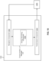
- Fig. 10 is a diagram of an example apparatus 1000 for wireless communication.
- the apparatus 1000 may be a base station, or a base station may include the apparatus 1000.
- the apparatus 1000 includes a reception component 1002 and a transmission component 1004, which may be in communication with one another (for example, via one or more buses and/or one or more other components).
- the apparatus 1000 may communicate with another apparatus 1006 (such as a UE, a base station, or another wireless communication device) using the reception component 1002 and the transmission component 1004.
- the apparatus 1000 may include the communication manager 150.
- the communication manager 150 may include an energy harvesting component 1008, among other examples.
- the apparatus 1000 may be configured to perform one or more operations described herein in connection with Figs. 3-5 . Additionally, or alternatively, the apparatus 1000 may be configured to perform one or more processes described herein, such as process 800 of Fig. 8 .
- the apparatus 1000 and/or one or more components shown in Fig. 10 may include one or more components of the base station described in connection with Fig. 2 . Additionally, or alternatively, one or more components shown in Fig. 10 may be implemented within one or more components described in connection with Fig. 2 . Additionally, or alternatively, one or more components of the set of components may be implemented at least in part as software stored in a memory. For example, a component (or a portion of a component) may be implemented as instructions or code stored in a non-transitory computer-readable medium and executable by a controller or a processor to perform the functions or operations of the component.
- the reception component 1002 may receive communications, such as reference signals, control information, data communications, or a combination thereof, from the apparatus 1006.
- the reception component 1002 may provide received communications to one or more other components of the apparatus 1000.
- the reception component 1002 may perform signal processing on the received communications (such as filtering, amplification, demodulation, analog-to-digital conversion, demultiplexing, deinterleaving, de-mapping, equalization, interference cancellation, or decoding, among other examples), and may provide the processed signals to the one or more other components of the apparatus 1000.
- the reception component 1002 may include one or more antennas, a modem, a demodulator, a MIMO detector, a receive processor, a controller/processor, a memory, or a combination thereof, of the base station described in connection with Fig. 2 .
- the transmission component 1004 may transmit communications, such as reference signals, control information, data communications, or a combination thereof, to the apparatus 1006.
- one or more other components of the apparatus 1000 may generate communications and may provide the generated communications to the transmission component 1004 for transmission to the apparatus 1006.
- the transmission component 1004 may perform signal processing on the generated communications (such as filtering, amplification, modulation, digital-to-analog conversion, multiplexing, interleaving, mapping, or encoding, among other examples), and may transmit the processed signals to the apparatus 1006.
- the transmission component 1004 may include one or more antennas, a modem, a modulator, a transmit MIMO processor, a transmit processor, a controller/processor, a memory, or a combination thereof, of the base station described in connection with Fig. 2 . In some aspects, the transmission component 1004 may be co-located with the reception component 1002 in a transceiver.
- the reception component 1002 may receive a PHR including data indicating PH for a UE, the PH indicating a difference between a maximum output power of the UE and an actual transmission power.
- the energy harvesting component 1008 may adjust an energy harvesting transmission process based at least in part on the PH satisfying a first threshold.
- the transmission component 1004 may transmit, to another UE, instructions to adjust energy harvesting associated with a target device.
- Fig. 10 The number and arrangement of components shown in Fig. 10 are provided as an example. In practice, there may be additional components, fewer components, different components, or differently arranged components than those shown in Fig. 10 . Furthermore, two or more components shown in Fig. 10 may be implemented within a single component, or a single component shown in Fig. 10 may be implemented as multiple, distributed components. Additionally, or alternatively, a set of (one or more) components shown in Fig. 10 may perform one or more functions described as being performed by another set of components shown in Fig. 10 .
- the term "component” is intended to be broadly construed as hardware and/or a combination of hardware and software.
- Software shall be construed broadly to mean instructions, instruction sets, code, code segments, program code, programs, subprograms, software modules, applications, software applications, software packages, routines, subroutines, objects, executables, threads of execution, procedures, and/or functions, among other examples, whether referred to as software, firmware, middleware, microcode, hardware description language, or otherwise.
- a "processor” is implemented in hardware and/or a combination of hardware and software. It will be apparent that systems and/or methods described herein may be implemented in different forms of hardware and/or a combination of hardware and software.
- satisfying a threshold may, depending on the context, refer to a value being greater than the threshold, greater than or equal to the threshold, less than the threshold, less than or equal to the threshold, equal to the threshold, not equal to the threshold, or the like.
- "at least one of: a, b, or c” is intended to cover a, b, c, a + b, a + c, b + c, and a + b + c, as well as any combination with multiples of the same element (e.g., a + a, a + a + a, a + a + b, a + a + c, a + b + b, a + c + c, b + b, b + b + b, b + b + c, c + c, and c + c + c, or any other ordering of a, b, and c).
- the terms “has,” “have,” “having,” or the like are intended to be open-ended terms that do not limit an element that they modify (e.g., an element “having” A may also have B).
- the phrase “based on” is intended to mean “based, at least in part, on” unless explicitly stated otherwise.
- the term “or” is intended to be inclusive when used in a series and may be used interchangeably with “and/or,” unless explicitly stated otherwise (e.g., if used in combination with "either” or “only one of').
Landscapes
- Engineering & Computer Science (AREA)
- Computer Networks & Wireless Communication (AREA)
- Power Engineering (AREA)
- Signal Processing (AREA)
- Mobile Radio Communication Systems (AREA)
Abstract
Description
- Aspects of the present disclosure generally relate to wireless communication and to techniques and apparatuses for energy harvesting based on power headroom.
- Wireless communication systems are widely deployed to provide various telecommunication services such as telephony, video, data, messaging, and broadcasts. Typical wireless communication systems may employ multiple-access technologies capable of supporting communication with multiple users by sharing available system resources (e.g., bandwidth, transmit power, or the like). Examples of such multiple-access technologies include code division multiple access (CDMA) systems, time division multiple access (TDMA) systems, frequency division multiple access (FDMA) systems, orthogonal frequency division multiple access (OFDMA) systems, single-carrier frequency division multiple access (SC-FDMA) systems, time division synchronous code division multiple access (TD-SCDMA) systems, and Long Term Evolution (LTE). LTE/LTE-Advanced is a set of enhancements to the Universal Mobile Telecommunications System (UMTS) mobile standard promulgated by the Third Generation Partnership Project (3GPP).
- A wireless network may include one or more base stations that support communication for a user equipment (UE) or multiple UEs. A UE may communicate with a base station via downlink communications and uplink communications. "Downlink" (or "DL") refers to a communication link from the base station to the UE, and "uplink" (or "UL") refers to a communication link from the UE to the base station.
- The above multiple access technologies have been adopted in various telecommunication standards to provide a common protocol that enables different UEs to communicate on a municipal, national, regional, and/or global level. New Radio (NR), which may be referred to as 5G, is a set of enhancements to the LTE mobile standard promulgated by the 3GPP. NR is designed to better support mobile broadband internet access by improving spectral efficiency, lowering costs, improving services, making use of new spectrum, and better integrating with other open standards using orthogonal frequency division multiplexing (OFDM) with a cyclic prefix (CP) (CP-OFDM) on the downlink, using CP-OFDM and/or single-carrier frequency division multiplexing (SC-FDM) (also known as discrete Fourier transform spread OFDM (DFT-s-OFDM)) on the uplink, as well as supporting beamforming, multiple-input multiple-output (MIMO) antenna technology, and carrier aggregation. As the demand for mobile broadband access continues to increase, further improvements in LTE, NR, and other radio access technologies remain useful.
- Some aspects described herein relate to a method of wireless communication performed by a user equipment (UE). The method may include transmitting a power headroom report (PHR) including data indicating power headroom (PH) for the UE, the PH indicating a difference between a maximum output power of the UE and an actual transmission power. The method may include adjusting an energy harvesting reception process based at least in part on the PH satisfying a first threshold.
- Some aspects described herein relate to a method of wireless communication performed by a UE. The method may include transmitting a PHR including data indicating PH for the UE, the PH indicating a difference between a maximum output power of the UE and an actual transmission power. The method may include adjusting an energy harvesting transmission process based at least in part on the PH satisfying a first threshold.
- Some aspects described herein relate to a method of wireless communication performed by a base station. The method may include receiving a PHR including data indicating PH for a UE, the PH indicating a difference between a maximum output power of the UE and an actual transmission power. The method may include adjusting an energy harvesting transmission process based at least in part on the PH satisfying a first threshold.
- Some aspects described herein relate to a UE for wireless communication. The user equipment may include a memory and one or more processors coupled to the memory. The one or more processors may be configured to transmit a PHR including data indicating PH for the UE, the PH indicating a difference between a maximum output power of the UE and an actual transmission power. The one or more processors may be configured to adjust an energy harvesting reception process based at least in part on the PH satisfying a first threshold.
- Some aspects described herein relate to a UE for wireless communication. The UE may include a memory and one or more processors coupled to the memory. The one or more processors may be configured to transmit a PHR including data indicating PH for the UE, the PH indicating a difference between a maximum output power of the UE and an actual transmission power. The one or more processors may be configured to adjust an energy harvesting transmission process based at least in part on the PH satisfying a first threshold.
- Some aspects described herein relate to a base station for wireless communication. The base station may include a memory and one or more processors coupled to the memory. The one or more processors may be configured to receive a PHR including data indicating PH for a UE, the PH indicating a difference between a maximum output power of the UE and an actual transmission power. The one or more processors may be configured to adjust an energy harvesting transmission process based at least in part on the PH satisfying a first threshold.
- Some aspects described herein relate to a non-transitory computer-readable medium that stores a set of instructions for wireless communication by a UE. The set of instructions, when executed by one or more processors of the UE, may cause the UE to transmit a PHR including data indicating PH for the UE, the PH indicating a difference between a maximum output power of the UE and an actual transmission power. The set of instructions, when executed by one or more processors of the UE, may cause the UE to adjust an energy harvesting reception process based at least in part on the PH satisfying a first threshold.
- Some aspects described herein relate to a non-transitory computer-readable medium that stores a set of instructions for wireless communication by a UE. The set of instructions, when executed by one or more processors of the UE, may cause the UE to transmit a PHR including data indicating PH for the UE, the PH indicating a difference between a maximum output power of the UE and an actual transmission power. The set of instructions, when executed by one or more processors of the UE, may cause the one or more processors of the UE to adjust an energy harvesting transmission process based at least in part on the PH satisfying a first threshold.
- Some aspects described herein relate to a non-transitory computer-readable medium that stores a set of instructions for wireless communication by a base station. The set of instructions, when executed by one or more processors of the base station, may cause the base station to receive a PHR including data indicating PH for a UE, the PH indicating a difference between a maximum output power of the UE and an actual transmission power. The set of instructions, when executed by one or more processors of the base station, may cause the base station to adjust an energy harvesting transmission process based at least in part on the PH satisfying a first threshold.
- Some aspects described herein relate to an apparatus for wireless communication. The apparatus may include means for transmitting a PHR including data indicating PH for a UE, the PH indicating a difference between a maximum output power of the UE and an actual transmission power. The apparatus may include means for adjusting an energy harvesting reception process based at least in part on the PH satisfying a first threshold.
- Some aspects described herein relate to an apparatus for wireless communication. The apparatus may include means for transmitting a PHR including data indicating PH for a UE, the PH indicating a difference between a maximum output power of the UE and an actual transmission power. The apparatus may include means for adjusting an energy harvesting transmission process based at least in part on the PH satisfying a first threshold.
- Some aspects described herein relate to an apparatus for wireless communication. The apparatus may include means for receiving a PHR including data indicating PH for a UE, the PH indicating a difference between a maximum output power of the UE and an actual transmission power. The apparatus may include means for adjusting an energy harvesting transmission process based at least in part on the PH satisfying a first threshold.
- Aspects generally include a method, apparatus, system, computer program product, non-transitory computer-readable medium, user equipment, base station, wireless communication device, and/or processing system as substantially described herein with reference to and as illustrated by the drawings and specification.
- The foregoing has outlined rather broadly the features and technical advantages of examples according to the disclosure in order that the detailed description that follows may be better understood. Additional features and advantages will be described hereinafter. The conception and specific examples disclosed may be readily utilized as a basis for modifying or designing other structures for carrying out the same purposes of the present disclosure. Such equivalent constructions do not depart from the scope of the appended claims. Characteristics of the concepts disclosed herein, both their organization and method of operation, together with associated advantages, will be better understood from the following description when considered in connection with the accompanying figures. Each of the figures is provided for the purposes of illustration and description, and not as a definition of the limits of the claims.
- While aspects are described in the present disclosure by illustration to some examples, those skilled in the art will understand that such aspects may be implemented in many different arrangements and scenarios. Techniques described herein may be implemented using different platform types, devices, systems, shapes, sizes, and/or packaging arrangements. For example, some aspects may be implemented via integrated chip embodiments or other non-module-component based devices (e.g., end-user devices, vehicles, communication devices, computing devices, industrial equipment, retail/purchasing devices, medical devices, and/or artificial intelligence devices). Aspects may be implemented in chip-level components, modular components, non-modular components, non-chip-level components, device-level components, and/or system-level components. Devices incorporating described aspects and features may include additional components and features for implementation and practice of claimed and described aspects. For example, transmission and reception of wireless signals may include one or more components for analog and digital purposes (e.g., hardware components including antennas, radio frequency (RF) chains, power amplifiers, modulators, buffers, processors, interleavers, adders, and/or summers). It is intended that aspects described herein may be practiced in a wide variety of devices, components, systems, distributed arrangements, and/or end-user devices of varying size, shape, and constitution.
- So that the above-recited features of the present disclosure can be understood in detail, a more particular description, briefly summarized above, may be had by reference to aspects, some of which are illustrated in the appended drawings. It is to be noted, however, that the appended drawings illustrate only certain typical aspects of this disclosure and are therefore not to be considered limiting of its scope, for the description may admit to other equally effective aspects. The same reference numbers in different drawings may identify the same or similar elements.
-
Fig. 1 is a diagram illustrating an example of a wireless network, in accordance with the present disclosure. -
Fig. 2 is a diagram illustrating an example of a base station in communication with a user equipment (UE) in a wireless network, in accordance with the present disclosure. -
Fig. 3 is a diagram illustrating an example of radio frequency energy harvesting, in accordance with the present disclosure. -
Fig. 4 is a diagram illustrating an example of power headroom reporting, in accordance with the present disclosure. -
Fig. 5 is a diagram illustrating an example associated with energy harvesting based on power headroom, in accordance with the present disclosure. -
Figs. 6-8 are diagrams illustrating example processes associated with energy harvesting based on power headroom, in accordance with the present disclosure. -
Figs. 9 and10 are diagrams of example apparatuses for wireless communication, in accordance with the present disclosure. - Various aspects of the disclosure are described more fully hereinafter with reference to the accompanying drawings. This disclosure may, however, be embodied in many different forms and should not be construed as limited to any specific structure or function presented throughout this disclosure. Rather, these aspects are provided so that this disclosure will be thorough and complete, and will fully convey the scope of the disclosure to those skilled in the art. One skilled in the art should appreciate that the scope of the disclosure is intended to cover any aspect of the disclosure disclosed herein, whether implemented independently of or combined with any other aspect of the disclosure. For example, an apparatus may be implemented or a method may be practiced using any number of the aspects set forth herein. In addition, the scope of the disclosure is intended to cover such an apparatus or method which is practiced using other structure, functionality, or structure and functionality in addition to or other than the various aspects of the disclosure set forth herein. It should be understood that any aspect of the disclosure disclosed herein may be embodied by one or more elements of a claim.
- Several aspects of telecommunication systems will now be presented with reference to various apparatuses and techniques. These apparatuses and techniques will be described in the following detailed description and illustrated in the accompanying drawings by various blocks, modules, components, circuits, steps, processes, algorithms, or the like (collectively referred to as "elements"). These elements may be implemented using hardware, software, or combinations thereof. Whether such elements are implemented as hardware or software depends upon the particular application and design constraints imposed on the overall system.
- While aspects may be described herein using terminology commonly associated with a 5G or New Radio (NR) radio access technology (RAT), aspects of the present disclosure can be applied to other RATs, such as a 3G RAT, a 4G RAT, and/or a RAT subsequent to 5G (e.g., 6G).
-
Fig. 1 is a diagram illustrating an example of awireless network 100, in accordance with the present disclosure. Thewireless network 100 may be or may include elements of a 5G (e.g., NR) network and/or a 4G (e.g., Long Term Evolution (LTE)) network, among other examples. Thewireless network 100 may include one or more base stations 110 (shown as aBS 110a, a BS 110b, aBS 110c, and aBS 110d), a user equipment (UE) 120 or multiple UEs 120 (shown as aUE 120a, aUE 120b, aUE 120c, aUE 120d, and aUE 120e), and/or other network entities. Abase station 110 is an entity that communicates withUEs 120. A base station 110 (sometimes referred to as a BS) may include, for example, an NR base station, an LTE base station, a Node B, an eNB (e.g., in 4G), a gNB (e.g., in 5G), an access point, and/or a transmission reception point (TRP). Eachbase station 110 may provide communication coverage for a particular geographic area. In the Third Generation Partnership Project (3GPP), the term "cell" can refer to a coverage area of abase station 110 and/or a base station subsystem serving this coverage area, depending on the context in which the term is used. - A
base station 110 may provide communication coverage for a macro cell, a pico cell, a femto cell, and/or another type of cell. A macro cell may cover a relatively large geographic area (e.g., several kilometers in radius) and may allow unrestricted access byUEs 120 with service subscriptions. A pico cell may cover a relatively small geographic area and may allow unrestricted access byUEs 120 with service subscription. A femto cell may cover a relatively small geographic area (e.g., a home) and may allow restricted access byUEs 120 having association with the femto cell (e.g.,UEs 120 in a closed subscriber group (CSG)). Abase station 110 for a macro cell may be referred to as a macro base station. Abase station 110 for a pico cell may be referred to as a pico base station. Abase station 110 for a femto cell may be referred to as a femto base station or an in-home base station. In the example shown inFig. 1 , theBS 110a may be a macro base station for amacro cell 102a, the BS 110b may be a pico base station for apico cell 102b, and theBS 110c may be a femto base station for afemto cell 102c. A base station may support one or multiple (e.g., three) cells. - In some examples, a cell may not necessarily be stationary, and the geographic area of the cell may move according to the location of a
base station 110 that is mobile (e.g., a mobile base station). In some examples, thebase stations 110 may be interconnected to one another and/or to one or moreother base stations 110 or network nodes (not shown) in thewireless network 100 through various types of backhaul interfaces, such as a direct physical connection or a virtual network, using any suitable transport network. - The
wireless network 100 may include one or more relay stations. A relay station is an entity that can receive a transmission of data from an upstream station (e.g., abase station 110 or a UE 120) and send a transmission of the data to a downstream station (e.g., aUE 120 or a base station 110). A relay station may be aUE 120 that can relay transmissions forother UEs 120. In the example shown inFig. 1 , theBS 110d (e.g., a relay base station) may communicate with theBS 110a (e.g., a macro base station) and theUE 120d in order to facilitate communication between theBS 110a and theUE 120d. Abase station 110 that relays communications may be referred to as a relay station, a relay base station, a relay, or the like. - The
wireless network 100 may be a heterogeneous network that includesbase stations 110 of different types, such as macro base stations, pico base stations, femto base stations, relay base stations, or the like. These different types ofbase stations 110 may have different transmit power levels, different coverage areas, and/or different impacts on interference in thewireless network 100. For example, macro base stations may have a high transmit power level (e.g., 5 to 40 watts) whereas pico base stations, femto base stations, and relay base stations may have lower transmit power levels (e.g., 0.1 to 2 watts). - A
network controller 130 may couple to or communicate with a set ofbase stations 110 and may provide coordination and control for thesebase stations 110. Thenetwork controller 130 may communicate with thebase stations 110 via a backhaul communication link. Thebase stations 110 may communicate with one another directly or indirectly via a wireless or wireline backhaul communication link. - The
UEs 120 may be dispersed throughout thewireless network 100, and eachUE 120 may be stationary or mobile. AUE 120 may include, for example, an access terminal, a terminal, a mobile station, and/or a subscriber unit. AUE 120 may be a cellular phone (e.g., a smart phone), a personal digital assistant (PDA), a wireless modem, a wireless communication device, a handheld device, a laptop computer, a cordless phone, a wireless local loop (WLL) station, a tablet, a camera, a gaming device, a netbook, a smartbook, an ultrabook, a medical device, a biometric device, a wearable device (e.g., a smart watch, smart clothing, smart glasses, a smart wristband, smart jewelry (e.g., a smart ring or a smart bracelet)), an entertainment device (e.g., a music device, a video device, and/or a satellite radio), a vehicular component or sensor, a smart meter/sensor, industrial manufacturing equipment, a global positioning system device, and/or any other suitable device that is configured to communicate via a wireless medium. - Some
UEs 120 may be considered machine-type communication (MTC) or evolved or enhanced machine-type communication (eMTC) UEs. An MTC UE and/or an eMTC UE may include, for example, a robot, a drone, a remote device, a sensor, a meter, a monitor, and/or a location tag, that may communicate with a base station, another device (e.g., a remote device), or some other entity. SomeUEs 120 may be considered Internet-of-Things (IoT) devices, and/or may be implemented as NB-IoT (narrowband IoT) devices. SomeUEs 120 may be considered a Customer Premises Equipment. AUE 120 may be included inside a housing that houses components of theUE 120, such as processor components and/or memory components. In some examples, the processor components and the memory components may be coupled together. For example, the processor components (e.g., one or more processors) and the memory components (e.g., a memory) may be operatively coupled, communicatively coupled, electronically coupled, and/or electrically coupled. - In general, any number of
wireless networks 100 may be deployed in a given geographic area. Eachwireless network 100 may support a particular RAT and may operate on one or more frequencies. A RAT may be referred to as a radio technology, an air interface, or the like. A frequency may be referred to as a carrier, a frequency channel, or the like. Each frequency may support a single RAT in a given geographic area in order to avoid interference between wireless networks of different RATs. In some cases, NR or 5G RAT networks may be deployed. - In some examples, two or more UEs 120 (e.g., shown as
UE 120a andUE 120e) may communicate directly using one or more sidelink channels (e.g., without using abase station 110 as an intermediary to communicate with one another). For example, theUEs 120 may communicate using peer-to-peer (P2P) communications, device-to-device (D2D) communications, a vehicle-to-everything (V2X) protocol (e.g., which may include a vehicle-to-vehicle (V2V) protocol, a vehicle-to-infrastructure (V2I) protocol, or a vehicle-to-pedestrian (V2P) protocol), and/or a mesh network. In such examples, aUE 120 may perform scheduling operations, resource selection operations, and/or other operations described elsewhere herein as being performed by thebase station 110. - Devices of the
wireless network 100 may communicate using the electromagnetic spectrum, which may be subdivided by frequency or wavelength into various classes, bands, channels, or the like. For example, devices of thewireless network 100 may communicate using one or more operating bands. In 5G NR, two initial operating bands have been identified as frequency range designations FR1 (410 MHz - 7.125 GHz) and FR2 (24.25 GHz - 52.6 GHz). It should be understood that although a portion of FR1 is greater than 6 GHz, FR1 is often referred to (interchangeably) as a "Sub-6 GHz" band in various documents and articles. A similar nomenclature issue sometimes occurs with regard to FR2, which is often referred to (interchangeably) as a "millimeter wave" band in documents and articles, despite being different from the extremely high frequency (EHF) band (30 GHz - 300 GHz) which is identified by the International Telecommunications Union (ITU) as a "millimeter wave" band. - The frequencies between FR1 and FR2 are often referred to as mid-band frequencies. Recent 5G NR studies have identified an operating band for these mid-band frequencies as frequency range designation FR3 (7.125 GHz - 24.25 GHz). Frequency bands falling within FR3 may inherit FR1 characteristics and/or FR2 characteristics, and thus may effectively extend features of FR1 and/or FR2 into mid-band frequencies. In addition, higher frequency bands are currently being explored to extend 5G NR operation beyond 52.6 GHz. For example, three higher operating bands have been identified as frequency range designations FR4a or FR4-1 (52.6 GHz - 71 GHz), FR4 (52.6 GHz - 114.25 GHz), and FR5 (114.25 GHz - 300 GHz). Each of these higher frequency bands falls within the EHF band.
- With the above examples in mind, unless specifically stated otherwise, it should be understood that the term "sub-6 GHz" or the like, if used herein, may broadly represent frequencies that may be less than 6 GHz, may be within FR1, or may include mid-band frequencies. Further, unless specifically stated otherwise, it should be understood that the term "millimeter wave" or the like, if used herein, may broadly represent frequencies that may include mid-band frequencies, may be within FR2, FR4, FR4-a or FR4-1, and/or FR5, or may be within the EHF band. It is contemplated that the frequencies included in these operating bands (e.g., FR1, FR2, FR3, FR4, FR4-a, FR4-1, and/or FR5) may be modified, and techniques described herein are applicable to those modified frequency ranges.
- In some aspects, the
UE 120 may include acommunication manager 140. As described in more detail elsewhere herein, thecommunication manager 140 may transmit a PHR including data indicating PH for the UE, the PH indicating a difference between a maximum output power of the UE and an actual transmission power; and adjust an energy harvesting reception process based at least in part on the PH satisfying a first threshold. As also described in more detail elsewhere herein, thecommunication manager 140 may transmit a PHR including data indicating PH for the UE, the PH indicating a difference between a maximum output power of the UE and an actual transmission power; and adjust an energy harvesting transmission process based at least in part on the PH satisfying a first threshold. Additionally, or alternatively, thecommunication manager 140 may perform one or more other operations described herein. - In some aspects, the
base station 110 may include acommunication manager 150. As described in more detail elsewhere herein, thecommunication manager 150 may receive a PHR including data indicating PH for a UE, the PH indicating a difference between a maximum output power of the UE and an actual transmission power; and adjust an energy harvesting transmission process based at least in part on the PH satisfying a first threshold. Additionally, or alternatively, thecommunication manager 150 may perform one or more other operations described herein. - As indicated above,
Fig. 1 is provided as an example. Other examples may differ from what is described with regard toFig. 1 . -
Fig. 2 is a diagram illustrating an example 200 of abase station 110 in communication with aUE 120 in awireless network 100, in accordance with the present disclosure. Thebase station 110 may be equipped with a set ofantennas 234a through 234t, such as T antennas (T ≥ 1). TheUE 120 may be equipped with a set ofantennas 252a through 252r, such as R antennas (R ≥ 1). - At the
base station 110, a transmitprocessor 220 may receive data, from adata source 212, intended for the UE 120 (or a set of UEs 120). The transmitprocessor 220 may select one or more modulation and coding schemes (MCSs) for theUE 120 based at least in part on one or more channel quality indicators (CQIs) received from thatUE 120. Thebase station 110 may process (e.g., encode and modulate) the data for theUE 120 based at least in part on the MCS(s) selected for theUE 120 and may provide data symbols for theUE 120. The transmitprocessor 220 may process system information (e.g., for semi-static resource partitioning information (SRPI)) and control information (e.g., CQI requests, grants, and/or upper layer signaling) and provide overhead symbols and control symbols. The transmitprocessor 220 may generate reference symbols for reference signals (e.g., a cell-specific reference signal (CRS) or a demodulation reference signal (DMRS)) and synchronization signals (e.g., a primary synchronization signal (PSS) or a secondary synchronization signal (SSS)). A transmit (TX) multiple-input multiple-output (MIMO)processor 230 may perform spatial processing (e.g., precoding) on the data symbols, the control symbols, the overhead symbols, and/or the reference symbols, if applicable, and may provide a set of output symbol streams (e.g., T output symbol streams) to a corresponding set of modems 232 (e.g., T modems), shown asmodems 232a through 232t. For example, each output symbol stream may be provided to a modulator component (shown as MOD) of a modem 232. Each modem 232 may use a respective modulator component to process a respective output symbol stream (e.g., for OFDM) to obtain an output sample stream. Each modem 232 may further use a respective modulator component to process (e.g., convert to analog, amplify, filter, and/or upconvert) the output sample stream to obtain a downlink signal. Themodems 232a through 232t may transmit a set of downlink signals (e.g., T downlink signals) via a corresponding set of antennas 234 (e.g., T antennas), shown asantennas 234a through 234t. - At the
UE 120, a set of antennas 252 (shown asantennas 252a through 252r) may receive the downlink signals from thebase station 110 and/orother base stations 110 and may provide a set of received signals (e.g., R received signals) to a set of modems 254 (e.g., R modems), shown asmodems 254a through 254r. For example, each received signal may be provided to a demodulator component (shown as DEMOD) of a modem 254. Each modem 254 may use a respective demodulator component to condition (e.g., filter, amplify, downconvert, and/or digitize) a received signal to obtain input samples. Each modem 254 may use a demodulator component to further process the input samples (e.g., for OFDM) to obtain received symbols. AMIMO detector 256 may obtain received symbols from the modems 254, may perform MIMO detection on the received symbols if applicable, and may provide detected symbols. A receiveprocessor 258 may process (e.g., demodulate and decode) the detected symbols, may provide decoded data for theUE 120 to adata sink 260, and may provide decoded control information and system information to a controller/processor 280. The term "controller/processor" may refer to one or more controllers, one or more processors, or a combination thereof. A channel processor may determine a reference signal received power (RSRP) parameter, a received signal strength indicator (RSSI) parameter, a reference signal received quality (RSRQ) parameter, and/or a CQI parameter, among other examples. In some examples, one or more components of theUE 120 may be included in ahousing 284. - The
network controller 130 may include acommunication unit 294, a controller/processor 290, and amemory 292. Thenetwork controller 130 may include, for example, one or more devices in a core network. Thenetwork controller 130 may communicate with thebase station 110 via thecommunication unit 294. - One or more antennas (e.g.,
antennas 234a through 234t and/orantennas 252a through 252r) may include, or may be included within, one or more antenna panels, one or more antenna groups, one or more sets of antenna elements, and/or one or more antenna arrays, among other examples. An antenna panel, an antenna group, a set of antenna elements, and/or an antenna array may include one or more antenna elements (within a single housing or multiple housings), a set of coplanar antenna elements, a set of non-coplanar antenna elements, and/or one or more antenna elements coupled to one or more transmission and/or reception components, such as one or more components ofFig. 2 . - On the uplink, at the
UE 120, a transmitprocessor 264 may receive and process data from adata source 262 and control information (e.g., for reports that include RSRP, RSSI, RSRQ, and/or CQI) from the controller/processor 280. The transmitprocessor 264 may generate reference symbols for one or more reference signals. The symbols from the transmitprocessor 264 may be precoded by aTX MIMO processor 266 if applicable, further processed by the modems 254 (e.g., for DFT-s-OFDM or CP-OFDM), and transmitted to thebase station 110. In some examples, the modem 254 of theUE 120 may include a modulator and a demodulator. In some examples, theUE 120 includes a transceiver. The transceiver may include any combination of the antenna(s) 252, the modem(s) 254, theMIMO detector 256, the receiveprocessor 258, the transmitprocessor 264, and/or theTX MIMO processor 266. The transceiver may be used by a processor (e.g., the controller/processor 280) and thememory 282 to perform aspects of any of the methods described herein (e.g., with reference toFigs. 5-10 ). - At the
base station 110, the uplink signals fromUE 120 and/or other UEs may be received by the antennas 234, processed by the modem 232 (e.g., a demodulator component, shown as DEMOD, of the modem 232), detected by aMIMO detector 236 if applicable, and further processed by a receiveprocessor 238 to obtain decoded data and control information sent by theUE 120. The receiveprocessor 238 may provide the decoded data to adata sink 239 and provide the decoded control information to the controller/processor 240. Thebase station 110 may include acommunication unit 244 and may communicate with thenetwork controller 130 via thecommunication unit 244. Thebase station 110 may include ascheduler 246 to schedule one ormore UEs 120 for downlink and/or uplink communications. In some examples, the modem 232 of thebase station 110 may include a modulator and a demodulator. In some examples, thebase station 110 includes a transceiver. The transceiver may include any combination of the antenna(s) 234, the modem(s) 232, theMIMO detector 236, the receiveprocessor 238, the transmitprocessor 220, and/or theTX MIMO processor 230. The transceiver may be used by a processor (e.g., the controller/processor 240) and thememory 242 to perform aspects of any of the methods described herein (e.g., with reference toFigs. 5-10 ). - The controller/
processor 240 of thebase station 110, the controller/processor 280 of theUE 120, and/or any other component(s) ofFig. 2 may perform one or more techniques associated with energy harvesting based on power headroom, as described in more detail elsewhere herein. For example, the controller/processor 240 of thebase station 110, the controller/processor 280 of theUE 120, and/or any other component(s) ofFig. 2 may perform or direct operations of, for example,process 600 ofFig. 6 ,process 700 ofFig. 7 ,process 800 ofFig. 8 , and/or other processes as described herein. Thememory 242 and thememory 282 may store data and program codes for thebase station 110 and theUE 120, respectively. In some examples, thememory 242 and/or thememory 282 may include a non-transitory computer-readable medium storing one or more instructions (e.g., code and/or program code) for wireless communication. For example, the one or more instructions, when executed (e.g., directly, or after compiling, converting, and/or interpreting) by one or more processors of thebase station 110 and/or theUE 120, may cause the one or more processors, theUE 120, and/or thebase station 110 to perform or direct operations of, for example,process 600 ofFig. 6 ,process 700 ofFig. 7 ,process 800 ofFig. 8 , and/or other processes as described herein. In some examples, executing instructions may include running the instructions, converting the instructions, compiling the instructions, and/or interpreting the instructions, among other examples. - In some aspects, the UE includes means for transmitting a PHR including data indicating PH for the UE, the PH indicating a difference between a maximum output power of the UE and an actual transmission power; and/or means for adjusting an energy harvesting reception process based at least in part on the PH satisfying a first threshold. In some aspects, the UE includes means for adjusting an energy harvesting transmission process based at least in part on the PH satisfying a first threshold. The means for the UE to perform operations described herein may include, for example, one or more of
communication manager 140, antenna 252, modem 254,MIMO detector 256, receiveprocessor 258, transmitprocessor 264,TX MIMO processor 266, controller/processor 280, ormemory 282. - In some aspects, the base station includes means for receiving a PHR including data indicating PH for a UE, the PH indicating a difference between a maximum output power of the UE and an actual transmission power; and/or means for adjusting an energy harvesting transmission process based at least in part on the PH satisfying a first threshold. The means for the base station to perform operations described herein may include, for example, one or more of
communication manager 150, transmitprocessor 220,TX MIMO processor 230, modem 232, antenna 234,MIMO detector 236, receiveprocessor 238, controller/processor 240,memory 242, orscheduler 246. - While blocks in
Fig. 2 are illustrated as distinct components, the functions described above with respect to the blocks may be implemented in a single hardware, software, or combination component or in various combinations of components. For example, the functions described with respect to the transmitprocessor 264, the receiveprocessor 258, and/or theTX MIMO processor 266 may be performed by or under the control of the controller/processor 280. - As indicated above,
Fig. 2 is provided as an example. Other examples may differ from what is described with regard toFig. 2 . -
Fig. 3 is a diagram illustrating an example 300 of radio frequency (RF) power headroom reporting, in accordance with the present disclosure. As shown inFig. 3 , an RF receiver (e.g., a UE 120) may receive signals (e.g., radio signals carried on radio waves) from an RF transmitter (e.g., abase station 110 or UE 120) and convert electromagnetic energy of the signals (e.g., using a rectenna comprising a dipole antenna with an RF diode) into direct current electricity for use by the RF receiver. - As shown by
reference number 305, in some aspects, the RF receiver may use a separated receiver architecture, where a first set of antennas is configured to harvest energy, and a second set of antennas is configured to receive data. In this situation, each set of antennas may be separately configured to receive signals at certain times, frequencies, and/or via one or more particular beams, such that all signals received by the first set of antennas are harvested for energy, and all signals received by the second set of antennas are processed to receive information. - As shown by
reference number 310, in some aspects, the RF receiver may use a time-switching architecture to harvest energy. The time switching architecture may use one or more antennas to receive signals, and whether the signals are harvested for energy or processed to receive information depends on the time at which the signals are received. For example, one or more first time slots may be time slots during which received signals are sent to one or more energy harvesting components to harvest energy, and one or more second time slots may be time slots during which received signals are processed and decoded to receive information. In some aspects, the time slots may be pre-configured (e.g., by the RF receiver, the RF transmitter, or another device). - As shown by
reference number 315, in some aspects, the RF receiver may use a power splitting architecture to harvest energy. The power splitting architecture may use one or more antennas to receive signals, and the signals are handled by one or both of the energy harvesting and/or information receiving components according to an energy harvesting rate. For example, the RF receiver may be configured to use a first portion of received signals for energy harvesting and the remaining received signals for information receiving. In some aspects, the energy harvesting rate may be pre-configured (e.g., by the RF receiver, the RF transmitter, or another device). - Energy harvested by the RF receiver may be used and/or stored for later use. For example, in some aspects, the RF receiver may be powered directly by the harvested energy. In some aspects, the RF receiver may use an energy storage device, such as a battery, capacitor, and/or supercapacitor, to gather and store harvested energy for immediate and/or later use.
- As indicated above,
Fig. 3 is provided as an example. Other examples may differ from what is described with respect toFig. 3 . -
Fig. 4 is a diagram illustrating an example 400 of power headroom reporting, in accordance with the present disclosure. As shown inFig. 4 , aPHR 410 may be transmitted from a UE (e.g., UE 120) to a base station (e.g., base station 110). ThePHR 410 is a UE generated report to the base station that provides the base station with an indication of how much power the UE has and/or is using. - The PH may indicate an amount of remaining transmission power available to a UE in addition to power being used by a current transmission. The PH may be based at least in part on a difference between a UE maximum transmission power and a physical uplink shared channel (PUSCH) transmission power. A PHR may be a
Type 1 report for a PUSCH, aType 3 report for a sounding reference signal (SRS), and/or aType 2 report for a physical uplink control channel (PUCCH). For example, types of UE PHRs may include aType 1 UE power headroom that is valid for a PUSCH transmission occasion i on an active uplink bandwidth part (BWP) b of carrier f of serving cell c, or aType 3 UE power headroom that is valid for an SRS transmission occasion i on an active uplink BWP b of carrier f of serving cell c. Thus, a PHR may be determined for a component carrier and/or serving cell. - A UE may determine whether a PH for an activated serving cell is based at least in part on an actual transmission. The actual transmission may be determined based at least in part on higher layer signalling of configured grant and periodic/semi-persistent SRS transmissions, and/or downlink control information (DCI) received by the UE. The UE may determine whether the PHR for the activated serving cell is based at least in part on a reference format. The reference format may be determined based at least in part on higher layer signalling of configured grant and periodic/semi-persistent SRS transmissions, and/or DCI received by the UE. A PHR for an activated serving cell may be referred to as a virtual PHR and/or may be provided via a virtual PHR.
- When a UE determines that a
Type 1 PH for an activated serving cell is based at least in part on an actual PUSCH transmission, for a PUSCH transmission occasion i on an active uplink BWP b of carrier f of serving cell c, the UE may compute theType 1 PH as:
- With respect to the
Type 1 PH (in dB) based at least in part on an actual PUSCH transmission, P CMAX,f,c (i) may represent a UE configured maximum output power after backoff due to power management (e.g., backoff due to a maximum power reduction), and P O_PUSCH,b,f,c (j),
- When the UE determines that a
Type 1 PH for an activated serving cell is based at least in part on a reference PUSCH transmission, for a PUSCH transmission occasion i on an active uplink BWP b of carrier f of serving cell c, the UE may compute theType 1 PH as: PHtype1,b,f,c (i, j, qd, l) = P̃ CMAX,f,c(i) - { P O_PUSCH,b,f,c (j) + αb,f,c (j) · PLb,f,c (qd ) + fb,f,c (i, l)} [dB] - With respect to the
Type 1 PH (in dB) based at least in part on a reference PUSCH transmission (e.g., a virtual power headroom report), P̃ CMAX,f,c (i) may be computed assuming no backoff (e.g., maximum power reduction (MPR) values may be assumed to be 0 dB), and P O_PUSCH,b,f,c (j), αb,f,c (j), PLb,f,c (qd ), and fb,f,c (i, l) may be based at least in part on default or reference parameters of j, i, l, and qd , where for P0 and alpha, p0-PUSCH AlphaSetld is equal to 0, and for path loss, pusch-PathlossReferenceRS-Id is equal to 0, and for closedloopindex, l is equal to 0. - A PHR may be triggered by a media access control (MAC) layer, and the PHR may be triggered based at least in part on an occurrence of one or more triggering events. For example, the PHR may be triggered by a set of timers, such as a phr-PeriodicTimer or a phr-ProhibitTimer. The PHR may be triggered by a power change that satisfies a configurable threshold for a pathloss reference signal used for power control in an uplink component carrier. The PHR may be triggered by an activation of a secondary cell (SCell). The PHR may be triggered when an active BWP of a configured component carrier is changed from a dormant state to a non-dormant state.
- A triggered PHR may be transmitted in a PHR MAC control element (MAC-CE) on a first available PUSCH corresponding to an initial transmission of a transport block that can accommodate the PHR MAC-CE as a result of logical channel prioritization. The PUSCH may be dynamic (e.g., scheduled by DCI), or the PUSCH can be a configured-grant PUSCH.
- A UE may be configured with multiple component carriers for a PUSCH transmission. The PHR MAC-CE may include a PHR for more than one component carrier when a multiplePHR parameter is enabled via radio resource control (RRC) signaling. Otherwise, the PHR may be a report for a primary cell (PCell) and a single-entry PHR MAC-CE format may be used. When a first PUSCH in a first component carrier carries the PHR MAC-CE, for a second component carrier, the PHR MAC-CE may include an actual PHR or a virtual PHR (based on a reference format). When a PUSCH transmission is performed on the second component carrier at a time of power headroom reporting (e.g., in a slot of the first PUSCH), and the PUSCH transmission on the second component carrier is scheduled by DCI that satisfies a timeline condition, the PHR MAC-CE may include the actual PHR. Otherwise, the MAC-CE may include the virtual PHR.
- The PHR MAC-CE may be a single-entry PHR MAC-CE, as shown by
reference number 410, or a multiple-entry PHR MAC-CE. The single-entry PHR MAC-CE may include a PH field, which may indicate a PH level for the PCell, and a PCMAX,f,c field, which may indicate the PCMAX,f,c used for calculating the preceding PH field. The multiple-entry PHR MAC-CE may include entries for the PCell and a plurality of SCells. For example, for the PCell or a given SCell, the multiple-entry PHR MAC-CE may include the corresponding PH field, the PCMAX,f,c field, a "V" value which may indicate whether a PH value in the PH field corresponds to a real transmission or a reference format, and a "P" value which may indicate whether power backoff is applied due to power management. - As shown by
reference number 410, the PH value of the PHR occupies a set of 6 bits, which provides a range from 0 to 63. The 64 PH values of the PHR are mapped to actual PH values (e.g., in dB) using PH lookup tables 420. As also shown byreference number 410, the PCMAX,f,c value, which was used to calculate the PH value, also occupies a set of 6 bits and also provides a range from 0 to 63. The 64 PCMAX,f,c values are mapped to actual PCMAX,f,c values (e.g., in dBm) using PCMAX,f,c lookup tables 430. The 'R' fields of the PHR may be reserved and/or populated with 0s. - As indicated above,
Fig. 4 is provided as an example. Other examples may differ from what is described with respect toFig. 4 . - In situations where energy harvesting is used, a UE may receive signals for energy harvesting on certain resources (e.g., time, frequency, and/or spatial resources) and at a certain power level that results in a particular charging rate. However, in situations where energy harvesting is not needed, or a different charging rate would be beneficial for the UE, fixed and/or periodic energy harvesting signals may be wasted and/or may not be at a rate appropriate for the UE's charging needs.
- Some techniques and apparatuses described herein enable a UE to adjust energy harvesting reception, and a base station to adjust energy harvesting transmission, based at least in part on a PHR. For example, the UE may transmit, and the base station may receive, a PHR that indicates the PH of the UE. Based at least in part on the PH satisfying a threshold, the UE and/or the base station may adjust energy harvesting reception and/or transmission, respectively. As a result, the UE and base station are able to receive and transmit, respectively, signals that are based on the needs of the UE as indicated by the PHR. In addition, in a situation where the UE is charging another device (e.g., another UE), the PHR may indicate that the other device should receive energy from a source other than the UE (e.g., in a situation where the UE needs to conserve power). This may prevent unnecessarily wasted energy harvesting signals from being transmitted, which may reduce power consumed by the base station and free up networking resources at both the transmitter and the receiver. In addition, the base station may be able to account for device charging needs by adjusting which UEs provide power to other devices based on the PHR(s) associated with the UEs.
-
Fig. 5 is a diagram illustrating an example 500 associated with energy harvesting based on power headroom, in accordance with the present disclosure. As shown inFig. 5 , a base station (e.g., base station 110) and a UE (e.g., UE 120) may communicate with one another. In addition, the base station may communicate with one or more other UEs (e.g., UEs 120), and both the UE and the other UE may communicate with an energy harvesting device (e.g., a UE 120). - As shown by
reference number 505, the UE may transmit, and the base station may receive, a PHR. As described herein, the PHR may include data indicating PH for the UE, the PH indicating a difference between a maximum output power of the UE and an actual transmission power. - In some aspects, the PH may be used (e.g., by the UE and/or base station) to infer whether subsequent energy harvesting is to be performed (e.g., based on power needs of the UE). For example, a relatively low PH (e.g., below one or more pre-configured thresholds) may indicate that the UE is operating at or near its peak output power. In a situation where the UE is receiving energy harvesting signals from the base station (or another UE), a low PH may indicate that the UE should activate, continue, or increase reception of energy harvesting signals to offset the relatively high output power. In a situation where the UE is transmitting energy harvesting signals (e.g., to an energy harvesting device), the low PH may indicate that the UE should cancel transmission of energy harvesting signals in order to lower output power (e.g., to conserve battery). As another example, a relatively high PH (e.g., above one or more pre-configured thresholds) may indicate that the UE is operating with a significant amount of available power. In a situation where the UE is receiving energy harvesting signals, a high PH may indicate that the UE should cancel reception of the energy harvesting signals, as the UE may not need energy harvesting. In a situation where the UE is transmitting energy harvesting signals, a high PH may indicate that the UE should activate, increase, or continue transmission of the energy harvesting signals, as the UE may have energy available to transmit for use by another device.
- As shown by
reference number 510, the UE may adjust an energy harvesting reception and/or transmission process. In some aspects, the UE may adjust the energy harvesting reception and/or transmission process based at least in part on the PH satisfying a first threshold. For example, the UE may adjust the energy harvesting reception and/or transmission process by activating or canceling energy harvesting reception, increasing a charging rate, decreasing a charging rate, and/or the like. - In some aspects, the adjustments to the energy harvesting reception and/or transmission process may be pre-configured, such that the UE and/or base station may make the adjustments based on the PHR report and a pre-configured mapping of PH values and/or thresholds to energy harvesting adjustments. In some aspects, the adjustment of the energy harvesting reception process is based at least in part on both the energy harvesting signal transmitter and receiver. When a UE is to be a recipient of energy harvesting signals, the UE may cause the energy harvesting transmitter to activate or cancel transmission of energy harvesting signals and/or adjust energy harvesting transmission parameters (e.g., MCS) by transmitting the PHR or, in some aspects, transmitting a separate indication. When a UE is transmitting energy harvesting signals, the UE may cause the energy harvesting receiver to activate or cancel reception of energy harvesting signals and/or adjust energy harvesting reception parameters (e.g., cause the energy harvesting device to monitor or not monitor resources for energy harvesting signals) by transmitting an indication to the energy harvesting device.
- In some aspects, the UE may adjust a charging rate associated with the energy harvesting reception and/or transmission process. For example, the UE may increase or decrease the charging rate by adjusting an amount of time the UE is to transmit or harvest energy from energy harvesting signals (e.g., in a time-switching architecture, as described herein) and/or adjusting a fraction of power allocated for energy harvesting (e.g., in a power-splitting architecture, as described herein). In some aspects, the charging rate may be associated with a percentage of signals being harvested, where data reception may be attempted on non-energy-harvested signals received by the UE. In some aspects, the charging rate may be increased and/or decreased by changing an MCS of the signals transmitted between the UE and the energy harvesting transmitter/receiver.
- In some aspects, the first threshold is one of multiple thresholds, and the multiple thresholds may be associated with respective ranges of PH values. In this situation, adjusting the energy harvesting reception and/or transmission process may be based at least in part on the respective range of PH values associated with the threshold satisfied by the PH indicated in the PHR. For example, there may be up to 64 different thresholds configured for the 64 different PH values capable of being reported in the PHR. Each range of PH values may be associated with a different rate of charging. For example, when the UE is receiving energy harvesting signals, thresholds associated with higher PH values may be associated with lower charging rates, while thresholds associated with lower PH values may be associated with higher charging rates. When the UE is transmitting energy harvesting signals, thresholds associated with higher PH values may be associated with higher charging rates, while thresholds associated with lower PH values may be associated with lower charging rates. The rate at which the charging rate changes between ranges of PH values may be linear or non-linear, and any number of thresholds and PH value ranges may be used to determine adjustments to energy harvesting charging rates (e.g., signals using a lower MCS may provide more energy to be harvested than signals transmitted using a higher MCS).
- In some aspects, adjusting the energy harvesting transmission and/or reception process may include continuing the energy harvesting transmission and/or reception process. For example, in a situation where conditions have not changed from transmission of a prior PHR, the energy harvesting transmitter and/or receiver may not need to make any changes to the energy harvesting transmission and/or reception, and may continue without making changes.
- In some aspects, the UE may be configured with a time delay between transmitting the PHR and receiving energy harvesting signals. In this situation, the UE may determine to adjust the energy harvesting reception process for an energy harvesting occasion based at least in part on the time delay satisfying a time threshold. For example, the time delay between transmission of the PHR and reception of energy harvesting signals may be relatively short, and the UE may be configured to wait until the time threshold is met before adjusting reception parameters for energy harvesting reception (e.g., to give the energy harvesting transmitter time to adjust transmission parameters based at least in part on the PHR).
- As shown by
reference number 515, the base station may adjust an energy harvesting transmission process based at least in part on the PH satisfying a first threshold. For example, the base station may make any adjustments described herein as being performed by the UE as an energy harvesting transmitter, such as activating or deactivating transmission of energy harvesting signals, adjusting a charging rate associated with energy harvesting signals, and/or the like. - As shown by
reference number 520a the base station may transmit, and the UE may receive, energy harvesting signals. As shown byreference number 520b, the UE may transmit energy harvesting signals to the energy harvesting device. As described herein, based at least in part on the adjustments to energy harvesting transmission and/or reception processes, the energy harvesting transmitter (e.g., the base station and/or the UE) may transmit the energy harvesting signals in accordance with the adjusted energy harvesting transmission/reception parameters. - As shown by
reference number 525, in some aspects, the base station may transmit instructions to another UE to perform an energy harvesting process. For example, in a situation where the UE is no longer transmitting energy harvesting signals to the energy harvesting device, and the energy harvesting device is still in need of energy, the base station may instruct the other UE to provide energy harvesting signals for the energy harvesting device instead of the UE. - As indicated above,
Fig. 5 is provided as an example. Other examples may differ from what is described with respect toFig. 5 . -
Fig. 6 is a diagram illustrating anexample process 600 performed, for example, by a UE, in accordance with the present disclosure.Example process 600 is an example where the UE (e.g., UE 120) performs operations associated with energy harvesting based on power headroom. - As shown in
Fig. 6 , in some aspects,process 600 may include transmitting a PHR including data indicating PH for the UE, the PH indicating a difference between a maximum output power of the UE and an actual transmission power (block 610). For example, the UE (e.g., usingcommunication manager 140 and/ortransmission component 904, depicted inFig. 9 ) may transmit a PHR including data indicating PH for the UE, the PH indicating a difference between a maximum output power of the UE and an actual transmission power, as described above. - As further shown in
Fig. 6 , in some aspects,process 600 may include adjusting an energy harvesting reception process based at least in part on the PH satisfying a first threshold (block 620). For example, the UE (e.g., usingcommunication manager 140 and/orenergy harvesting component 908, depicted inFig. 9 ) may adjust an energy harvesting reception process based at least in part on the PH satisfying a first threshold, as described above. -
Process 600 may include additional aspects, such as any single aspect or any combination of aspects described below and/or in connection with one or more other processes described elsewhere herein. - In a first aspect, a time delay between the PHR and an energy harvesting occasion of the energy harvesting reception process satisfies a time threshold, and adjusting the energy harvesting reception process comprises canceling energy harvesting reception for the energy harvesting occasion based at least in part on the time delay satisfying the time threshold.
- In a second aspect, alone or in combination with the first aspect, a time delay between the PHR and an energy harvesting occasion is within a pre-configured time window, and adjusting the energy harvesting reception process comprises canceling energy harvesting reception for the energy harvesting occasion based at least in part on the time delay being within the pre-configured time window.
- In a third aspect, alone or in combination with one or more of the first and second aspects, a time delay between the PHR and an energy harvesting occasion is pre-configured.
- In a fourth aspect, alone or in combination with one or more of the first through third aspects, adjusting the energy harvesting reception process comprises increasing a charging rate associated with the energy harvesting reception process.
- In a fifth aspect, alone or in combination with one or more of the first through fourth aspects, adjusting the energy harvesting reception process comprises decreasing a charging rate associated with the energy harvesting reception process.
- In a sixth aspect, alone or in combination with one or more of the first through fifth aspects, the first threshold is one of a plurality of thresholds, wherein each of the plurality of thresholds is associated with a respective range of PH values, and wherein adjusting the energy harvesting reception process comprises adjusting the energy harvesting reception process based on the respective range of PH values associated with the first threshold.
- In a seventh aspect, alone or in combination with one or more of the first through sixth aspects, each of the respective ranges of PH values is associated with a different charging rate, and adjusting the energy harvesting reception process further comprises setting a charging rate associated with the energy harvesting reception process based at least in part on one of the respective ranges of PH values associated with the first threshold.
- Although
Fig. 6 shows example blocks ofprocess 600, in some aspects,process 600 may include additional blocks, fewer blocks, different blocks, or differently arranged blocks than those depicted inFig. 6 . Additionally, or alternatively, two or more of the blocks ofprocess 600 may be performed in parallel. -
Fig. 7 is a diagram illustrating anexample process 700 performed, for example, by a UE, in accordance with the present disclosure.Example process 700 is an example where the UE (e.g., UE 120) performs operations associated with energy harvesting based on power headroom. - As shown in
Fig. 7 , in some aspects,process 700 may include transmitting a PHR including data indicating PH for the UE, the PH indicating a difference between a maximum output power of the UE and an actual transmission power (block 710). For example, the UE (e.g., usingcommunication manager 140 and/ortransmission component 904, depicted inFig. 9 ) may transmit a PHR including data indicating PH for the UE, the PH indicating a difference between a maximum output power of the UE and an actual transmission power, as described above. - As further shown in
Fig. 7 , in some aspects,process 700 may include adjusting an energy harvesting transmission process based at least in part on the PH satisfying a first threshold (block 720). For example, the UE (e.g., usingcommunication manager 140 and/orenergy harvesting component 908, depicted inFig. 9 ) may adjust an energy harvesting transmission process based at least in part on the PH satisfying a first threshold, as described above. -
Process 700 may include additional aspects, such as any single aspect or any combination of aspects described below and/or in connection with one or more other processes described elsewhere herein. - In a first aspect,
process 700 includes adjusting the energy harvesting transmission process based at least in part on expiration of an energy harvesting timer. - In a second aspect, alone or in combination with the first aspect, adjusting the energy harvesting transmission process comprises canceling energy harvesting transmission based at least in part on the PH being below the first threshold.
- In a third aspect, alone or in combination with one or more of the first and second aspects, adjusting the energy harvesting transmission process comprises activating energy harvesting transmission based at least in part on the PH being above the first threshold.
- In a fourth aspect, alone or in combination with one or more of the first through third aspects, adjusting the energy harvesting transmission process comprises increasing a charging rate associated with the energy harvesting transmission process.
- In a fifth aspect, alone or in combination with one or more of the first through fourth aspects, adjusting the energy harvesting transmission process comprises decreasing a charging rate associated with the energy harvesting transmission process.
- In a sixth aspect, alone or in combination with one or more of the first through fifth aspects, the first threshold is one of a plurality of thresholds, wherein each of the plurality of thresholds is associated with a respective range of PH values, and wherein adjusting the energy harvesting transmission process comprises adjusting the energy harvesting transmission process based on the respective range of PH values associated with the first threshold.
- In a seventh aspect, alone or in combination with one or more of the first through sixth aspects, each of the respective ranges of PH values is associated with a different charging rate, and adjusting the energy harvesting transmission process further comprises setting a charging rate associated with the energy harvesting transmission process based at least in part on one of the respective ranges of PH values associated with the first threshold.
- Although
Fig. 7 shows example blocks ofprocess 700, in some aspects,process 700 may include additional blocks, fewer blocks, different blocks, or differently arranged blocks than those depicted inFig. 7 . Additionally, or alternatively, two or more of the blocks ofprocess 700 may be performed in parallel. -
Fig. 8 is a diagram illustrating anexample process 800 performed, for example, by a base station, in accordance with the present disclosure.Example process 800 is an example where the base station (e.g., base station 110) performs operations associated with energy harvesting based on power headroom. - As shown in
Fig. 8 , in some aspects,process 800 may include receiving a PHR including data indicating PH for a UE, the PH indicating a difference between a maximum output power of the UE and an actual transmission power (block 810). For example, the base station (e.g., usingcommunication manager 150 and/orreception component 1002, depicted inFig. 10 ) may receive a PHR including data indicating PH for a UE, the PH indicating a difference between a maximum output power of the UE and an actual transmission power, as described above. - As further shown in
Fig. 8 , in some aspects,process 800 may include adjusting an energy harvesting transmission process based at least in part on the PH satisfying a first threshold (block 820). For example, the base station (e.g., usingcommunication manager 150 and/orenergy harvesting component 1008, depicted inFig. 10 ) may adjust an energy harvesting transmission process based at least in part on the PH satisfying a first threshold, as described above. -
Process 800 may include additional aspects, such as any single aspect or any combination of aspects described below and/or in connection with one or more other processes described elsewhere herein. - In a first aspect,
process 800 includes transmitting, to another UE, instructions to adjust energy harvesting associated with a target device. - In a second aspect, alone or in combination with the first aspect, adjusting the energy harvesting transmission process comprises canceling energy harvesting transmission based at least in part on the PH being above the first threshold.
- In a third aspect, alone or in combination with one or more of the first and second aspects, adjusting the energy harvesting transmission process comprises activating energy harvesting transmission based at least in part on the PH being below the first threshold.
- In a fourth aspect, alone or in combination with one or more of the first through third aspects, adjusting the energy harvesting transmission process comprises increasing a charging rate associated with the energy harvesting transmission process.
- In a fifth aspect, alone or in combination with one or more of the first through fourth aspects, adjusting the energy harvesting transmission process comprises decreasing a charging rate associated with the energy harvesting transmission process.
- In a sixth aspect, alone or in combination with one or more of the first through fifth aspects, the first threshold is one of a plurality of thresholds, wherein each of the plurality of thresholds is associated with a respective range of PH values, and wherein adjusting the energy harvesting transmission process comprises adjusting the energy harvesting transmission process based on the respective range of PH values associated with the first threshold.
- In a seventh aspect, alone or in combination with one or more of the first through sixth aspects, each of the respective ranges of PH values is associated with a different charging rate, and adjusting the energy harvesting transmission process further comprises setting a charging rate associated with the energy harvesting transmission process based at least in part on one of the respective ranges of PH values associated with the first threshold.
- Although
Fig. 8 shows example blocks ofprocess 800, in some aspects,process 800 may include additional blocks, fewer blocks, different blocks, or differently arranged blocks than those depicted inFig. 8 . Additionally, or alternatively, two or more of the blocks ofprocess 800 may be performed in parallel. -
Fig. 9 is a diagram of anexample apparatus 900 for wireless communication. Theapparatus 900 may be a UE, or a UE may include theapparatus 900. In some aspects, theapparatus 900 includes areception component 902 and atransmission component 904, which may be in communication with one another (for example, via one or more buses and/or one or more other components). As shown, theapparatus 900 may communicate with another apparatus 906 (such as a UE, a base station, or another wireless communication device) using thereception component 902 and thetransmission component 904. As further shown, theapparatus 900 may include thecommunication manager 140. Thecommunication manager 140 may include one or more of anenergy harvesting component 908, among other examples. - In some aspects, the
apparatus 900 may be configured to perform one or more operations described herein in connection withFigs. 3-5 . Additionally, or alternatively, theapparatus 900 may be configured to perform one or more processes described herein, such asprocess 600 ofFig. 6 ,process 700 ofFig. 7 , or a combination thereof. In some aspects, theapparatus 900 and/or one or more components shown inFig. 9 may include one or more components of the UE described in connection withFig. 2 . Additionally, or alternatively, one or more components shown inFig. 9 may be implemented within one or more components described in connection withFig. 2 . Additionally, or alternatively, one or more components of the set of components may be implemented at least in part as software stored in a memory. For example, a component (or a portion of a component) may be implemented as instructions or code stored in a non-transitory computer-readable medium and executable by a controller or a processor to perform the functions or operations of the component. - The
reception component 902 may receive communications, such as reference signals, control information, data communications, or a combination thereof, from theapparatus 906. Thereception component 902 may provide received communications to one or more other components of theapparatus 900. In some aspects, thereception component 902 may perform signal processing on the received communications (such as filtering, amplification, demodulation, analog-to-digital conversion, demultiplexing, deinterleaving, de-mapping, equalization, interference cancellation, or decoding, among other examples), and may provide the processed signals to the one or more other components of theapparatus 900. In some aspects, thereception component 902 may include one or more antennas, a modem, a demodulator, a MIMO detector, a receive processor, a controller/processor, a memory, or a combination thereof, of the UE described in connection withFig. 2 . - The
transmission component 904 may transmit communications, such as reference signals, control information, data communications, or a combination thereof, to theapparatus 906. In some aspects, one or more other components of theapparatus 900 may generate communications and may provide the generated communications to thetransmission component 904 for transmission to theapparatus 906. In some aspects, thetransmission component 904 may perform signal processing on the generated communications (such as filtering, amplification, modulation, digital-to-analog conversion, multiplexing, interleaving, mapping, or encoding, among other examples), and may transmit the processed signals to theapparatus 906. In some aspects, thetransmission component 904 may include one or more antennas, a modem, a modulator, a transmit MIMO processor, a transmit processor, a controller/processor, a memory, or a combination thereof, of the UE described in connection withFig. 2 . In some aspects, thetransmission component 904 may be co-located with thereception component 902 in a transceiver. - The
transmission component 904 may transmit a PHR including data indicating PH for the UE, the PH indicating a difference between a maximum output power of the UE and an actual transmission power. Theenergy harvesting component 908 may adjust an energy harvesting reception process based at least in part on the PH satisfying a first threshold. - The number and arrangement of components shown in
Fig. 9 are provided as an example. In practice, there may be additional components, fewer components, different components, or differently arranged components than those shown inFig. 9 . Furthermore, two or more components shown inFig. 9 may be implemented within a single component, or a single component shown inFig. 9 may be implemented as multiple, distributed components. Additionally, or alternatively, a set of (one or more) components shown inFig. 9 may perform one or more functions described as being performed by another set of components shown inFig. 9 . -
Fig. 10 is a diagram of anexample apparatus 1000 for wireless communication. Theapparatus 1000 may be a base station, or a base station may include theapparatus 1000. In some aspects, theapparatus 1000 includes areception component 1002 and atransmission component 1004, which may be in communication with one another (for example, via one or more buses and/or one or more other components). As shown, theapparatus 1000 may communicate with another apparatus 1006 (such as a UE, a base station, or another wireless communication device) using thereception component 1002 and thetransmission component 1004. As further shown, theapparatus 1000 may include thecommunication manager 150. Thecommunication manager 150 may include anenergy harvesting component 1008, among other examples. - In some aspects, the
apparatus 1000 may be configured to perform one or more operations described herein in connection withFigs. 3-5 . Additionally, or alternatively, theapparatus 1000 may be configured to perform one or more processes described herein, such asprocess 800 ofFig. 8 . In some aspects, theapparatus 1000 and/or one or more components shown inFig. 10 may include one or more components of the base station described in connection withFig. 2 . Additionally, or alternatively, one or more components shown inFig. 10 may be implemented within one or more components described in connection withFig. 2 . Additionally, or alternatively, one or more components of the set of components may be implemented at least in part as software stored in a memory. For example, a component (or a portion of a component) may be implemented as instructions or code stored in a non-transitory computer-readable medium and executable by a controller or a processor to perform the functions or operations of the component. - The
reception component 1002 may receive communications, such as reference signals, control information, data communications, or a combination thereof, from theapparatus 1006. Thereception component 1002 may provide received communications to one or more other components of theapparatus 1000. In some aspects, thereception component 1002 may perform signal processing on the received communications (such as filtering, amplification, demodulation, analog-to-digital conversion, demultiplexing, deinterleaving, de-mapping, equalization, interference cancellation, or decoding, among other examples), and may provide the processed signals to the one or more other components of theapparatus 1000. In some aspects, thereception component 1002 may include one or more antennas, a modem, a demodulator, a MIMO detector, a receive processor, a controller/processor, a memory, or a combination thereof, of the base station described in connection withFig. 2 . - The
transmission component 1004 may transmit communications, such as reference signals, control information, data communications, or a combination thereof, to theapparatus 1006. In some aspects, one or more other components of theapparatus 1000 may generate communications and may provide the generated communications to thetransmission component 1004 for transmission to theapparatus 1006. In some aspects, thetransmission component 1004 may perform signal processing on the generated communications (such as filtering, amplification, modulation, digital-to-analog conversion, multiplexing, interleaving, mapping, or encoding, among other examples), and may transmit the processed signals to theapparatus 1006. In some aspects, thetransmission component 1004 may include one or more antennas, a modem, a modulator, a transmit MIMO processor, a transmit processor, a controller/processor, a memory, or a combination thereof, of the base station described in connection withFig. 2 . In some aspects, thetransmission component 1004 may be co-located with thereception component 1002 in a transceiver. - The
reception component 1002 may receive a PHR including data indicating PH for a UE, the PH indicating a difference between a maximum output power of the UE and an actual transmission power. Theenergy harvesting component 1008 may adjust an energy harvesting transmission process based at least in part on the PH satisfying a first threshold. - The
transmission component 1004 may transmit, to another UE, instructions to adjust energy harvesting associated with a target device. - The number and arrangement of components shown in
Fig. 10 are provided as an example. In practice, there may be additional components, fewer components, different components, or differently arranged components than those shown inFig. 10 . Furthermore, two or more components shown inFig. 10 may be implemented within a single component, or a single component shown inFig. 10 may be implemented as multiple, distributed components. Additionally, or alternatively, a set of (one or more) components shown inFig. 10 may perform one or more functions described as being performed by another set of components shown inFig. 10 . - The following provides an overview of some Aspects of the present disclosure:
- Aspect 1: A method of wireless communication performed by a UE, comprising: transmitting a PHR including data indicating PH for the UE, the PH indicating a difference between a maximum output power of the UE and an actual transmission power; and adjusting an energy harvesting reception process based at least in part on the PH satisfying a first threshold.
- Aspect 2: The method of
Aspect 1, wherein a time delay between the PHR and an energy harvesting occasion of the energy harvesting reception process satisfies a time threshold; and wherein adjusting the energy harvesting reception process comprises canceling energy harvesting reception for the energy harvesting occasion based at least in part on the time delay satisfying the time threshold. - Aspect 3: The method of any of Aspects 1-2, wherein a time delay between the PHR and an energy harvesting occasion is within a pre-configured time window; and wherein adjusting the energy harvesting reception process comprises canceling energy harvesting reception for the energy harvesting occasion based at least in part on the time delay being within the pre-configured time window.
- Aspect 4: The method of any of Aspects 1-3, wherein a time delay between the PHR and an energy harvesting occasion is pre-configured.
- Aspect 5: The method of any of Aspects 1-4, wherein adjusting the energy harvesting reception process comprises increasing a charging rate associated with the energy harvesting reception process.
- Aspect 6: The method of any of Aspects 1-5, wherein adjusting the energy harvesting reception process comprises decreasing a charging rate associated with the energy harvesting reception process.
- Aspect 7: The method of any of Aspects 1-6, wherein the first threshold is one of a plurality of thresholds, wherein each of the plurality of thresholds is associated with a respective range of PH values, and wherein adjusting the energy harvesting reception process comprises: adjusting the energy harvesting reception process based on the respective range of PH values associated with the first threshold.
- Aspect 8: The method of Aspect 7, wherein each of the respective ranges of PH values is associated with a different charging rate; and wherein adjusting the energy harvesting reception process further comprises: setting a charging rate associated with the energy harvesting reception process based at least in part on one of the respective ranges of PH values associated with the first threshold.
- Aspect 9: A method of wireless communication performed by a UE, comprising: transmitting a PHR including data indicating PH for the UE, the PH indicating a difference between a maximum output power of the UE and an actual transmission power; and adjusting an energy harvesting transmission process based at least in part on the PH satisfying a first threshold.
- Aspect 10: The method of Aspect 9, further comprising: adjusting the energy harvesting transmission process based at least in part on expiration of an energy harvesting timer.
- Aspect 11: The method of any of Aspects 9-10, wherein adjusting the energy harvesting transmission process comprises canceling energy harvesting transmission based at least in part on the PH being below the first threshold.
- Aspect 12: The method of any of Aspects 9-11, wherein adjusting the energy harvesting transmission process comprises activating energy harvesting transmission based at least in part on the PH being above the first threshold.
- Aspect 13: The method of any of Aspects 9-12, wherein adjusting the energy harvesting transmission process comprises increasing a charging rate associated with the energy harvesting transmission process.
- Aspect 14: The method of any of Aspects 9-13, wherein adjusting the energy harvesting transmission process comprises decreasing a charging rate associated with the energy harvesting transmission process.
- Aspect 15: The method of any of Aspects 9-14, wherein the first threshold is one of a plurality of thresholds, wherein each of the plurality of thresholds is associated with a respective range of PH values, and wherein adjusting the energy harvesting transmission process comprises: adjusting the energy harvesting transmission process based on the respective range of PH values associated with the first threshold.
- Aspect 16: The method of Aspect 15, wherein each of the respective ranges of PH values is associated with a different charging rate; and wherein adjusting the energy harvesting transmission process further comprises: setting a charging rate associated with the energy harvesting transmission process based at least in part on one of the respective ranges of PH values associated with the first threshold.
- Aspect 17: A method of wireless communication performed by a base station, comprising: receiving a PHR including data indicating PH for a UE, the PH indicating a difference between a maximum output power of the UE and an actual transmission power; and adjusting an energy harvesting transmission process based at least in part on the PH satisfying a first threshold.
- Aspect 18: The method of Aspect 17, further comprising: transmitting, to another UE, instructions to adjust energy harvesting associated with a target device.
- Aspect 19: The method of any of Aspects 17-18, wherein adjusting the energy harvesting transmission process comprises canceling energy harvesting transmission based at least in part on the PH being above the first threshold.
- Aspect 20: The method of any of Aspects 17-19, wherein adjusting the energy harvesting transmission process comprises activating energy harvesting transmission based at least in part on the PH being below the first threshold.
- Aspect 21: The method of any of Aspects 17-20, wherein adjusting the energy harvesting transmission process comprises increasing a charging rate associated with the energy harvesting transmission process.
- Aspect 22: The method of any of Aspects 17-21, wherein adjusting the energy harvesting transmission process comprises decreasing a charging rate associated with the energy harvesting transmission process.
- Aspect 23: The method of any of Aspects 17-22, wherein the first threshold is one of a plurality of thresholds, wherein each of the plurality of thresholds is associated with a respective range of PH values, and wherein adjusting the energy harvesting transmission process comprises: adjusting the energy harvesting transmission process based on the respective range of PH values associated with the first threshold.
- Aspect 24: The method of Aspect 23, wherein each of the respective ranges of PH values is associated with a different charging rate; and wherein adjusting the energy harvesting transmission process further comprises: setting a charging rate associated with the energy harvesting transmission process based at least in part on one of the respective ranges of PH values associated with the first threshold.
- Aspect 25: An apparatus for wireless communication at a device, comprising a processor; memory coupled with the processor; and instructions stored in the memory and executable by the processor to cause the apparatus to perform the method of one or more of Aspects 1-8.
- Aspect 26: An apparatus for wireless communication at a device, comprising a processor; memory coupled with the processor; and instructions stored in the memory and executable by the processor to cause the apparatus to perform the method of one or more of Aspects 9-16.
- Aspect 27: An apparatus for wireless communication at a device, comprising a processor; memory coupled with the processor; and instructions stored in the memory and executable by the processor to cause the apparatus to perform the method of one or more of Aspects 17-24.
- Aspect 28: A device for wireless communication, comprising a memory and one or more processors coupled to the memory, the one or more processors configured to perform the method of one or more of Aspects 1-8.
- Aspect 26: A device for wireless communication, comprising a memory and one or more processors coupled to the memory, the one or more processors configured to perform the method of one or more of Aspects 9-16.
- Aspect 29: A device for wireless communication, comprising a memory and one or more processors coupled to the memory, the one or more processors configured to perform the method of one or more of Aspects 17-24.
- Aspect 30: An apparatus for wireless communication, comprising at least one means for performing the method of one or more of Aspects 1-8.
- Aspect 31: An apparatus for wireless communication, comprising at least one means for performing the method of one or more of Aspects 9-16.
- Aspect 32: An apparatus for wireless communication, comprising at least one means for performing the method of one or more of Aspects 17-24.
- Aspect 33: A non-transitory computer-readable medium storing code for wireless communication, the code comprising instructions executable by a processor to perform the method of one or more of Aspects 1-8.
- Aspect 34: A non-transitory computer-readable medium storing code for wireless communication, the code comprising instructions executable by a processor to perform the method of one or more of Aspects 9-16.
- Aspect 35: A non-transitory computer-readable medium storing code for wireless communication, the code comprising instructions executable by a processor to perform the method of one or more of Aspects 17-24.
- Aspect 36: A non-transitory computer-readable medium storing a set of instructions for wireless communication, the set of instructions comprising one or more instructions that, when executed by one or more processors of a device, cause the device to perform the method of one or more of Aspects 1-8.
- Aspect 37: A non-transitory computer-readable medium storing a set of instructions for wireless communication, the set of instructions comprising one or more instructions that, when executed by one or more processors of a device, cause the device to perform the method of one or more of Aspects 9-16.
- Aspect 38: A non-transitory computer-readable medium storing a set of instructions for wireless communication, the set of instructions comprising one or more instructions that, when executed by one or more processors of a device, cause the device to perform the method of one or more of Aspects 17-24.
- The foregoing disclosure provides illustration and description but is not intended to be exhaustive or to limit the aspects to the precise forms disclosed. Modifications and variations may be made in light of the above disclosure or may be acquired from practice of the aspects.
- As used herein, the term "component" is intended to be broadly construed as hardware and/or a combination of hardware and software. "Software" shall be construed broadly to mean instructions, instruction sets, code, code segments, program code, programs, subprograms, software modules, applications, software applications, software packages, routines, subroutines, objects, executables, threads of execution, procedures, and/or functions, among other examples, whether referred to as software, firmware, middleware, microcode, hardware description language, or otherwise. As used herein, a "processor" is implemented in hardware and/or a combination of hardware and software. It will be apparent that systems and/or methods described herein may be implemented in different forms of hardware and/or a combination of hardware and software. The actual specialized control hardware or software code used to implement these systems and/or methods is not limiting of the aspects. Thus, the operation and behavior of the systems and/or methods are described herein without reference to specific software code, since those skilled in the art will understand that software and hardware can be designed to implement the systems and/or methods based, at least in part, on the description herein.
- As used herein, "satisfying a threshold" may, depending on the context, refer to a value being greater than the threshold, greater than or equal to the threshold, less than the threshold, less than or equal to the threshold, equal to the threshold, not equal to the threshold, or the like.
- Even though particular combinations of features are recited in the claims and/or disclosed in the specification, these combinations are not intended to limit the disclosure of various aspects. Many of these features may be combined in ways not specifically recited in the claims and/or disclosed in the specification. The disclosure of various aspects includes each dependent claim in combination with every other claim in the claim set. As used herein, a phrase referring to "at least one of' a list of items refers to any combination of those items, including single members. As an example, "at least one of: a, b, or c" is intended to cover a, b, c, a + b, a + c, b + c, and a + b + c, as well as any combination with multiples of the same element (e.g., a + a, a + a + a, a + a + b, a + a + c, a + b + b, a + c + c, b + b, b + b + b, b + b + c, c + c, and c + c + c, or any other ordering of a, b, and c).
- No element, act, or instruction used herein should be construed as critical or essential unless explicitly described as such. Also, as used herein, the articles "a" and "an" are intended to include one or more items and may be used interchangeably with "one or more." Further, as used herein, the article "the" is intended to include one or more items referenced in connection with the article "the" and may be used interchangeably with "the one or more." Furthermore, as used herein, the terms "set" and "group" are intended to include one or more items and may be used interchangeably with "one or more." Where only one item is intended, the phrase "only one" or similar language is used. Also, as used herein, the terms "has," "have," "having," or the like are intended to be open-ended terms that do not limit an element that they modify (e.g., an element "having" A may also have B). Further, the phrase "based on" is intended to mean "based, at least in part, on" unless explicitly stated otherwise. Also, as used herein, the term "or" is intended to be inclusive when used in a series and may be used interchangeably with "and/or," unless explicitly stated otherwise (e.g., if used in combination with "either" or "only one of').
-
- 1. A user equipment (UE) for wireless communication, comprising: a memory; and one or more processors, coupled to the memory, configured to: transmit a power headroom report (PHR) including data indicating power headroom (PH) for the UE, the PH indicating a difference between a maximum output power of the UE and an actual transmission power; andadjust an energy harvesting reception process based at least in part on the PH satisfying a first threshold.
- 2. The UE of example 1, wherein a time delay between the PHR and an energy harvesting occasion of the energy harvesting reception process satisfies a time threshold; and wherein the one or more processors, to adjust the energy harvesting reception process, are configured to cancel energy harvesting reception for the energy harvesting occasion based at least in part on the time delay satisfying the time threshold.
- 3. The UE of example 1, wherein a time delay between the PHR and an energy harvesting occasion is within a pre-configured time window; and wherein the one or more processors, to adjust the energy harvesting reception process, are configured to cancel energy harvesting reception for the energy harvesting occasion based at least in part on the time delay being within the pre-configured time window.
- 4. The UE of example 1, wherein a time delay between the PHR and an energy harvesting occasion is pre-configured.
- 5. The UE of example 1, wherein the one or more processors, to adjust the energy harvesting reception process, are configured to increase a charging rate associated with the energy harvesting reception process.
- 6. The UE of example 1, wherein the one or more processors, to adjust the energy harvesting reception process, are configured to decrease a charging rate associated with the energy harvesting reception process.
- 7. The UE of example 1, wherein the first threshold is one of a plurality of thresholds, wherein each of the plurality of thresholds is associated with a respective range of PH values, and wherein the one or more processors, to adjust the energy harvesting reception process, are configured to: adjust the energy harvesting reception process based on the respective range of PH values associated with the first threshold.
- 8. The UE of example 7, wherein each of the respective ranges of PH values is associated with a different charging rate; and wherein the one or more processors, to adjust the energy harvesting reception process, are configured to: set a charging rate associated with the energy harvesting reception process based at least in part on one of the respective ranges of PH values associated with the first threshold.
- 9. A user equipment (UE) for wireless communication, comprising: a memory; and one or more processors, coupled to the memory, configured to: transmit a power headroom report (PHR) including data indicating power headroom (PH) for the UE, the PH indicating a difference between a maximum output power of the UE and an actual transmission power; and adjust an energy harvesting transmission process based at least in part on the PH satisfying a first threshold.
- 10. The UE of example 9, wherein the one or more processors are further configured to:adjust the energy harvesting transmission process based at least in part on expiration of an energy harvesting timer.
- 11. The UE of example 9, wherein the one or more processors, to adjust the energy harvesting transmission process, are configured to cancel energy harvesting transmission based at least in part on the PH being below the first threshold.
- 12. The UE of example 9, wherein the one or more processors, to adjust the energy harvesting transmission process, are configured to activate energy harvesting transmission based at least in part on the PH being above the first threshold.
- 13. The UE of example 9, wherein the one or more processors, to adjust the energy harvesting transmission process, are configured to increase a charging rate associated with the energy harvesting transmission process.
- 14. The UE of example 9, wherein the one or more processors, to adjust the energy harvesting transmission process, are configured to decrease a charging rate associated with the energy harvesting transmission process.
- 15. The UE of example 9, wherein the first threshold is one of a plurality of thresholds, wherein each of the plurality of thresholds is associated with a respective range of PH values, and wherein the one or more processors, to adjust the energy harvesting reception process, are configured to: adjust the energy harvesting transmission process based on the respective range of PH values associated with the first threshold.
- 16. The UE of example 15, wherein each of the respective ranges of PH values is associated with a different charging rate; and wherein the one or more processors, to adjust the energy harvesting transmission process, are configured to: set a charging rate associated with the energy harvesting transmission process based at least in part on one of the respective ranges of PH values associated with the first threshold.
- 17. A base station for wireless communication, comprising: a memory; and one or more processors, coupled to the memory, configured to: receive a power headroom report (PHR) including data indicating power headroom (PH) for a user equipment (UE), the PH indicating a difference between a maximum output power of the UE and an actual transmission power; and adjust an energy harvesting transmission process based at least in part on the PH satisfying a first threshold.
- 18. The base station of example 17, wherein the one or more processors are further configured to: transmit, to another UE, instructions to adjust energy harvesting associated with a target device.
- 19. The base station of example 17, wherein the one or more processors, to adjust the energy harvesting transmission process, are configured to cancel energy harvesting transmission based at least in part on the PH being above the first threshold.
- 20. The base station of example 17, wherein the one or more processors, to adjust the energy harvesting transmission process, are configured to activate energy harvesting transmission based at least in part on the PH being below the first threshold.
- 21. The base station of example 17, wherein the one or more processors, to adjust the energy harvesting transmission process, are configured to increase a charging rate associated with the energy harvesting transmission process.
- 22. The base station of example 17, wherein the one or more processors, to adjust the energy harvesting transmission process, are configured to decrease a charging rate associated with the energy harvesting transmission process.
- 23. The base station of example 17, wherein the first threshold is one of a plurality of thresholds, wherein each of the plurality of thresholds is associated with a respective range of PH values, and wherein the one or more processors, to adjust the energy harvesting reception process, are configured to: adjust the energy harvesting transmission process based on the respective range of PH values associated with the first threshold.
- 24. The base station of example 23, wherein each of the respective ranges of PH values is associated with a different charging rate; and wherein the one or more processors, to adjust the energy harvesting transmission process, are configured to: set a charging rate associated with the energy harvesting transmission process based at least in part on one of the respective ranges of PH values associated with the first threshold.
- 25. A method of wireless communication performed by a user equipment (UE), comprising: transmitting a power headroom report (PHR) including data indicating power headroom (PH) for the UE, the PH indicating a difference between a maximum output power of the UE and an actual transmission power; and adjusting an energy harvesting process based at least in part on the PH satisfying a first threshold.
- 26. The method of example 25, wherein a time delay between the PHR and an energy harvesting occasion of the energy harvesting process satisfies a time threshold; andwherein adjusting the energy harvesting process comprises canceling energy harvesting for the energy harvesting occasion based at least in part on the time delay satisfying the time threshold.
- 27. The method of example 25, wherein adjusting the energy harvesting process comprises increasing a charging rate associated with the energy harvesting process.
- 28. The method of example 25, wherein adjusting the energy harvesting process comprises decreasing a charging rate associated with the energy harvesting process.
- 29. The method of example 25, wherein the first threshold is one of a plurality of thresholds, wherein each of the plurality of thresholds is associated with a respective range of PH values, and wherein adjusting the energy harvesting process comprises: adjusting the energy harvesting process based on the respective range of PH values associated with the first threshold.
- 30. The method of example 29, wherein each of the respective ranges of PH values is associated with a different charging rate; and wherein adjusting the energy harvesting process further comprises: setting a charging rate associated with the energy harvesting process based at least in part on one of the respective ranges of PH values associated with the first threshold.
Claims (15)
- A user equipment, UE (120) for wireless communication, comprising:a memory (282); andone or more processors (280), coupled to the memory, configured to:transmit (710) a power headroom report, PHR, including data indicating power headroom, PH, for the UE, the PH indicating a difference between a maximum output power of the UE and an actual transmission power; andadjust (720) an energy harvesting transmission process based at least in part on the PH satisfying a first threshold.
- The UE of claim 1, wherein the one or more processors are further configured to:
adjust the energy harvesting transmission process based at least in part on expiration of an energy harvesting timer. - The UE of claim 1, wherein the one or more processors, to adjust the energy harvesting transmission process, are configured to cancel energy harvesting transmission based at least in part on the PH being below the first threshold.
- The UE of claim 1, wherein the one or more processors, to adjust the energy harvesting transmission process, are configured to activate energy harvesting transmission based at least in part on the PH being above the first threshold.
- The UE of claim 1, wherein the one or more processors, to adjust the energy harvesting transmission process, are configured to increase a charging rate associated with the energy harvesting transmission process.
- The UE of claim 1, wherein the one or more processors, to adjust the energy harvesting transmission process, are configured to decrease a charging rate associated with the energy harvesting transmission process.
- The UE of claim 1, wherein the first threshold is one of a plurality of thresholds, wherein each of the plurality of thresholds is associated with a respective range of PH values, and wherein the one or more processors, to adjust the energy harvesting reception process, are configured to:adjust the energy harvesting transmission process based on the respective range of PH values associated with the first threshold.
- The UE of claim 7, wherein each of the respective ranges of PH values is associated with a different charging rate; and
wherein the one or more processors, to adjust the energy harvesting transmission process, are configured to:
set a charging rate associated with the energy harvesting transmission process based at least in part on one of the respective ranges of PH values associated with the first threshold. - A method (700) of wireless communication performed by a user equipment, UE (120), comprising:transmitting (710) a power headroom report, PHR, including data indicating power headroom, PH, for the UE, the PH indicating a difference between a maximum output power of the UE and an actual transmission power; andadjusting (720) an energy harvesting transmission process based at least in part on the PH satisfying a first threshold.
- The method of claim 9, wherein a time delay between the PHR and an energy harvesting occasion of the energy harvesting process satisfies a time threshold; and
wherein adjusting the energy harvesting process comprises canceling energy harvesting for the energy harvesting occasion based at least in part on the time delay satisfying the time threshold. - The method of claim 9, wherein adjusting the energy harvesting process comprises increasing a charging rate associated with the energy harvesting process; or wherein adjusting the energy harvesting process comprises decreasing a charging rate associated with the energy harvesting process.
- The method of claim 9, wherein the first threshold is one of a plurality of thresholds, wherein each of the plurality of thresholds is associated with a respective range of PH values, and wherein adjusting the energy harvesting process comprises:
adjusting the energy harvesting process based on the respective range of PH values associated with the first threshold. - The method of claim 12, wherein each of the respective ranges of PH values is associated with a different charging rate; and
wherein adjusting the energy harvesting process further comprises:
setting a charging rate associated with the energy harvesting process based at least in part on one of the respective ranges of PH values associated with the first threshold. - A base station (110) for wireless communication, comprising:a memory (242); andone or more processors (240), coupled to the memory, configured to:receive (810) a power headroom report, PHR, including data indicating power headroom, PH, for a user equipment, UE (120), the PH indicating a difference between a maximum output power of the UE and an actual transmission power; andadjust (820) an energy harvesting transmission process based at least in part on the PH satisfying a first threshold.
- A method (800) of wireless communication performed by a base station (110), comprising:receiving (810) a power headroom report, PHR, including data indicating power headroom, PH, for a user equipment, UE (120), the PH indicating a difference between a maximum output power of the UE and an actual transmission power; andadjusting (820) an energy harvesting transmission process based at least in part on the PH satisfying a first threshold.
Applications Claiming Priority (3)
| Application Number | Priority Date | Filing Date | Title |
|---|---|---|---|
| US17/451,467 US11917556B2 (en) | 2021-10-19 | 2021-10-19 | Energy harvesting based on power headroom |
| PCT/US2022/078009 WO2023069856A1 (en) | 2021-10-19 | 2022-10-13 | Energy harvesting based on power headroom |
| EP22802434.5A EP4420433A1 (en) | 2021-10-19 | 2022-10-13 | Energy harvesting based on power headroom |
Related Parent Applications (1)
| Application Number | Title | Priority Date | Filing Date |
|---|---|---|---|
| EP22802434.5A Division EP4420433A1 (en) | 2021-10-19 | 2022-10-13 | Energy harvesting based on power headroom |
Publications (2)
| Publication Number | Publication Date |
|---|---|
| EP4459838A2 true EP4459838A2 (en) | 2024-11-06 |
| EP4459838A3 EP4459838A3 (en) | 2025-01-22 |
Family
ID=84332379
Family Applications (2)
| Application Number | Title | Priority Date | Filing Date |
|---|---|---|---|
| EP24201350.6A Pending EP4459838A3 (en) | 2021-10-19 | 2022-10-13 | Energy harvesting based on power headroom |
| EP22802434.5A Pending EP4420433A1 (en) | 2021-10-19 | 2022-10-13 | Energy harvesting based on power headroom |
Family Applications After (1)
| Application Number | Title | Priority Date | Filing Date |
|---|---|---|---|
| EP22802434.5A Pending EP4420433A1 (en) | 2021-10-19 | 2022-10-13 | Energy harvesting based on power headroom |
Country Status (4)
| Country | Link |
|---|---|
| US (1) | US11917556B2 (en) |
| EP (2) | EP4459838A3 (en) |
| CN (1) | CN118077260A (en) |
| WO (1) | WO2023069856A1 (en) |
Family Cites Families (29)
| Publication number | Priority date | Publication date | Assignee | Title |
|---|---|---|---|---|
| US9900204B2 (en) * | 2010-04-20 | 2018-02-20 | Qorvo Us, Inc. | Multiple functional equivalence digital communications interface |
| US9077405B2 (en) * | 2010-04-20 | 2015-07-07 | Rf Micro Devices, Inc. | High efficiency path based power amplifier circuitry |
| US9048787B2 (en) * | 2010-04-20 | 2015-06-02 | Rf Micro Devices, Inc. | Combined RF detector and RF attenuator with concurrent outputs |
| US20120025752A1 (en) * | 2010-07-28 | 2012-02-02 | Triune Ip Llc | Battery charger |
| CN102196542B (en) * | 2011-05-27 | 2014-06-25 | 上海华为技术有限公司 | Power control method, equipment and system |
| US8774074B2 (en) * | 2011-11-02 | 2014-07-08 | Qualcomm Incorporated | Apparatus and method for adaptively enabling discontinuous transmission (DTX) in a wireless communication system |
| US10324920B2 (en) * | 2013-07-17 | 2019-06-18 | Douglass Malcolm | Residential management system |
| US20150282091A1 (en) * | 2014-03-28 | 2015-10-01 | Qualcomm Incorporated | Method for DSDS/DSDA Idle Power Optimization by Adaptive RF Power Retention and Delta Programming |
| US10964426B2 (en) * | 2015-10-16 | 2021-03-30 | General Electric Company | Methods and systems to sense situational awareness with a dual doppler and control for optimized operations |
| US10532268B2 (en) * | 2016-05-02 | 2020-01-14 | Bao Tran | Smart device |
| US10462541B2 (en) * | 2017-03-24 | 2019-10-29 | Keithley Instruments, Llc | Determination and rendering of scan groups |
| KR102024866B1 (en) | 2017-08-29 | 2019-09-25 | 한국산업기술대학교산학협력단 | Adaptive wireless power transmission method and system |
| US11329522B2 (en) | 2018-03-07 | 2022-05-10 | Telefonaktiebolaget Lm Ericsson (Publ) | Technique for wirelessly charging a wireless device in a wireless communication system |
| US10997251B2 (en) * | 2018-10-15 | 2021-05-04 | Bao Tran | Smart device |
| US12043140B2 (en) * | 2019-05-29 | 2024-07-23 | Neutron Holdings, Inc. | Rechargeable battery including power connection condition monitoring system |
| WO2021231454A1 (en) * | 2020-05-13 | 2021-11-18 | Rearden Power LLC | Hybrid battery management system |
| US11805488B2 (en) * | 2020-08-10 | 2023-10-31 | Qualcomm Incorporated | Power headroom reporting for uplink component carriers |
| US11722972B2 (en) * | 2020-08-21 | 2023-08-08 | Qualcomm Incorporated | Power headroom reporting for uplink shared channel repetition |
| WO2022046324A1 (en) * | 2020-08-28 | 2022-03-03 | Supply, Inc. | Method and system for wireless power delivery |
| WO2022109428A1 (en) * | 2020-11-20 | 2022-05-27 | Poltorak Technologies Llc | Multiple partially redundant biometric sensing devices |
| US20240107465A1 (en) * | 2021-01-15 | 2024-03-28 | Qualcomm Incorporated | Multi-panel power headroom reporting |
| US20220352751A1 (en) * | 2021-04-30 | 2022-11-03 | Qualcomm Incorporated | Signaling for energy harvesting |
| EP4367941A4 (en) * | 2021-07-09 | 2025-03-19 | QUALCOMM Incorporated | BEAM-SPECIFIC VIRTUAL POWER RESERVE REPORT |
| CN113473422B (en) | 2021-07-21 | 2022-06-21 | 深圳市领创星通科技有限公司 | B5G-oriented wireless energy-carrying D2D network efficient resource allocation method |
| US11956732B2 (en) * | 2021-09-28 | 2024-04-09 | Qualcomm Incorporated | Autonomous physical uplink shared channel repetition cancellation for energy-limited devices |
| US12500444B2 (en) * | 2021-10-19 | 2025-12-16 | Qualcomm Incorporated | Energy harvesting reporting |
| US11968632B2 (en) * | 2021-12-01 | 2024-04-23 | Qualcomm Incorporated | Power control adaptation |
| US11881714B2 (en) * | 2022-02-28 | 2024-01-23 | Qualcomm Incorporated | Energy harvesting management |
| WO2023166022A1 (en) * | 2022-03-01 | 2023-09-07 | Telefonaktiebolaget Lm Ericsson (Publ) | Maximum output power of a communication device reflecting stored energy |
-
2021
- 2021-10-19 US US17/451,467 patent/US11917556B2/en active Active
-
2022
- 2022-10-13 EP EP24201350.6A patent/EP4459838A3/en active Pending
- 2022-10-13 WO PCT/US2022/078009 patent/WO2023069856A1/en not_active Ceased
- 2022-10-13 CN CN202280067858.2A patent/CN118077260A/en active Pending
- 2022-10-13 EP EP22802434.5A patent/EP4420433A1/en active Pending
Also Published As
| Publication number | Publication date |
|---|---|
| US11917556B2 (en) | 2024-02-27 |
| WO2023069856A1 (en) | 2023-04-27 |
| EP4420433A1 (en) | 2024-08-28 |
| US20230120756A1 (en) | 2023-04-20 |
| EP4459838A3 (en) | 2025-01-22 |
| CN118077260A (en) | 2024-05-24 |
Similar Documents
| Publication | Publication Date | Title |
|---|---|---|
| KR102871302B1 (en) | Power Headroom Reporting for Uplink Component Carriers | |
| US12363649B2 (en) | Power headroom reporting for uplink shared channel repetition | |
| US20240414657A1 (en) | Configuring separate power control adjustment states for sounding reference signal transmissions | |
| US11910333B2 (en) | MPE-aware transmission scheduling | |
| WO2023137734A1 (en) | Multiple power headroom value reporting for multiple transmission reception point scenarios with simultaneous transmissions | |
| US11881714B2 (en) | Energy harvesting management | |
| WO2022151307A1 (en) | Multi-panel power headroom reporting | |
| US12143946B2 (en) | Beam-specific virtual power headroom reporting | |
| US11968632B2 (en) | Power control adaptation | |
| US20250374181A1 (en) | Uplink transmission during a cell sleep mode operation | |
| EP4427369B1 (en) | Within slot repetition for improved coverage, energy harvesting, and/or automatic gain control | |
| WO2023173274A1 (en) | Techniques for reporting multiple parameter values in power headroom report | |
| EP4459838A2 (en) | Energy harvesting based on power headroom | |
| US20240389090A1 (en) | Skipping control element uplink transmissions when using semi-persistent scheduling | |
| WO2023204936A1 (en) | Cell active time configuration | |
| WO2022154988A1 (en) | Aperiodic sounding reference signal triggering without data scheduling |
Legal Events
| Date | Code | Title | Description |
|---|---|---|---|
| PUAI | Public reference made under article 153(3) epc to a published international application that has entered the european phase |
Free format text: ORIGINAL CODE: 0009012 |
|
| STAA | Information on the status of an ep patent application or granted ep patent |
Free format text: STATUS: THE APPLICATION HAS BEEN PUBLISHED |
|
| AC | Divisional application: reference to earlier application |
Ref document number: 4420433 Country of ref document: EP Kind code of ref document: P |
|
| AK | Designated contracting states |
Kind code of ref document: A2 Designated state(s): AL AT BE BG CH CY CZ DE DK EE ES FI FR GB GR HR HU IE IS IT LI LT LU LV MC ME MK MT NL NO PL PT RO RS SE SI SK SM TR |
|
| REG | Reference to a national code |
Ref country code: DE Ref legal event code: R079 Free format text: PREVIOUS MAIN CLASS: H02J0050200000 Ipc: H04W0052360000 |
|
| PUAL | Search report despatched |
Free format text: ORIGINAL CODE: 0009013 |
|
| AK | Designated contracting states |
Kind code of ref document: A3 Designated state(s): AL AT BE BG CH CY CZ DE DK EE ES FI FR GB GR HR HU IE IS IT LI LT LU LV MC ME MK MT NL NO PL PT RO RS SE SI SK SM TR |
|
| RIC1 | Information provided on ipc code assigned before grant |
Ipc: H02J 50/20 20160101ALI20241216BHEP Ipc: H04W 52/36 20090101AFI20241216BHEP |
|
| STAA | Information on the status of an ep patent application or granted ep patent |
Free format text: STATUS: REQUEST FOR EXAMINATION WAS MADE |
|
| 17P | Request for examination filed |
Effective date: 20250721 |
|
| GRAP | Despatch of communication of intention to grant a patent |
Free format text: ORIGINAL CODE: EPIDOSNIGR1 |
|
| STAA | Information on the status of an ep patent application or granted ep patent |
Free format text: STATUS: GRANT OF PATENT IS INTENDED |
|
| INTG | Intention to grant announced |
Effective date: 20250925 |