EP4459831A1 - Method for equalization current regulation and energy support of battery cells - Google Patents
Method for equalization current regulation and energy support of battery cells Download PDFInfo
- Publication number
- EP4459831A1 EP4459831A1 EP24169562.6A EP24169562A EP4459831A1 EP 4459831 A1 EP4459831 A1 EP 4459831A1 EP 24169562 A EP24169562 A EP 24169562A EP 4459831 A1 EP4459831 A1 EP 4459831A1
- Authority
- EP
- European Patent Office
- Prior art keywords
- cell
- equalization
- segment
- flag
- energy
- Prior art date
- Legal status (The legal status is an assumption and is not a legal conclusion. Google has not performed a legal analysis and makes no representation as to the accuracy of the status listed.)
- Pending
Links
Images


Classifications
-
- H—ELECTRICITY
- H02—GENERATION; CONVERSION OR DISTRIBUTION OF ELECTRIC POWER
- H02J—ELECTRIC POWER NETWORKS; CIRCUIT ARRANGEMENTS OR SYSTEMS FOR SUPPLYING OR DISTRIBUTING ELECTRIC POWER; SYSTEMS FOR STORING ELECTRIC ENERGY
- H02J7/00—Circuit arrangements for charging or discharging batteries or for supplying loads from batteries
-
- B—PERFORMING OPERATIONS; TRANSPORTING
- B60—VEHICLES IN GENERAL
- B60L—PROPULSION OF ELECTRICALLY-PROPELLED VEHICLES; SUPPLYING ELECTRIC POWER FOR AUXILIARY EQUIPMENT OF ELECTRICALLY-PROPELLED VEHICLES; ELECTRODYNAMIC BRAKE SYSTEMS FOR VEHICLES IN GENERAL; MAGNETIC SUSPENSION OR LEVITATION FOR VEHICLES; MONITORING OPERATING VARIABLES OF ELECTRICALLY-PROPELLED VEHICLES; ELECTRIC SAFETY DEVICES FOR ELECTRICALLY-PROPELLED VEHICLES
- B60L58/00—Methods or circuit arrangements for monitoring or controlling batteries or fuel cells, specially adapted for electric vehicles
- B60L58/10—Methods or circuit arrangements for monitoring or controlling batteries or fuel cells, specially adapted for electric vehicles for monitoring or controlling batteries
- B60L58/18—Methods or circuit arrangements for monitoring or controlling batteries or fuel cells, specially adapted for electric vehicles for monitoring or controlling batteries of two or more battery modules
- B60L58/22—Balancing the charge of battery modules
-
- H—ELECTRICITY
- H02—GENERATION; CONVERSION OR DISTRIBUTION OF ELECTRIC POWER
- H02J—ELECTRIC POWER NETWORKS; CIRCUIT ARRANGEMENTS OR SYSTEMS FOR SUPPLYING OR DISTRIBUTING ELECTRIC POWER; SYSTEMS FOR STORING ELECTRIC ENERGY
- H02J7/00—Circuit arrangements for charging or discharging batteries or for supplying loads from batteries
- H02J7/50—Circuit arrangements for charging or discharging batteries or for supplying loads from batteries acting upon multiple batteries simultaneously or sequentially
- H02J7/52—Circuit arrangements for charging or discharging batteries or for supplying loads from batteries acting upon multiple batteries simultaneously or sequentially for charge balancing, e.g. equalisation of charge between batteries
- H02J7/56—Active balancing, e.g. using capacitor-based, inductor-based or DC-DC converters
-
- B—PERFORMING OPERATIONS; TRANSPORTING
- B60—VEHICLES IN GENERAL
- B60L—PROPULSION OF ELECTRICALLY-PROPELLED VEHICLES; SUPPLYING ELECTRIC POWER FOR AUXILIARY EQUIPMENT OF ELECTRICALLY-PROPELLED VEHICLES; ELECTRODYNAMIC BRAKE SYSTEMS FOR VEHICLES IN GENERAL; MAGNETIC SUSPENSION OR LEVITATION FOR VEHICLES; MONITORING OPERATING VARIABLES OF ELECTRICALLY-PROPELLED VEHICLES; ELECTRIC SAFETY DEVICES FOR ELECTRICALLY-PROPELLED VEHICLES
- B60L58/00—Methods or circuit arrangements for monitoring or controlling batteries or fuel cells, specially adapted for electric vehicles
- B60L58/10—Methods or circuit arrangements for monitoring or controlling batteries or fuel cells, specially adapted for electric vehicles for monitoring or controlling batteries
- B60L58/16—Methods or circuit arrangements for monitoring or controlling batteries or fuel cells, specially adapted for electric vehicles for monitoring or controlling batteries responding to battery ageing, e.g. to the number of charging cycles or the state of health [SoH]
-
- B—PERFORMING OPERATIONS; TRANSPORTING
- B60—VEHICLES IN GENERAL
- B60L—PROPULSION OF ELECTRICALLY-PROPELLED VEHICLES; SUPPLYING ELECTRIC POWER FOR AUXILIARY EQUIPMENT OF ELECTRICALLY-PROPELLED VEHICLES; ELECTRODYNAMIC BRAKE SYSTEMS FOR VEHICLES IN GENERAL; MAGNETIC SUSPENSION OR LEVITATION FOR VEHICLES; MONITORING OPERATING VARIABLES OF ELECTRICALLY-PROPELLED VEHICLES; ELECTRIC SAFETY DEVICES FOR ELECTRICALLY-PROPELLED VEHICLES
- B60L58/00—Methods or circuit arrangements for monitoring or controlling batteries or fuel cells, specially adapted for electric vehicles
- B60L58/10—Methods or circuit arrangements for monitoring or controlling batteries or fuel cells, specially adapted for electric vehicles for monitoring or controlling batteries
- B60L58/18—Methods or circuit arrangements for monitoring or controlling batteries or fuel cells, specially adapted for electric vehicles for monitoring or controlling batteries of two or more battery modules
- B60L58/20—Methods or circuit arrangements for monitoring or controlling batteries or fuel cells, specially adapted for electric vehicles for monitoring or controlling batteries of two or more battery modules having different nominal voltages
-
- G—PHYSICS
- G01—MEASURING; TESTING
- G01R—MEASURING ELECTRIC VARIABLES; MEASURING MAGNETIC VARIABLES
- G01R31/00—Arrangements for testing electric properties; Arrangements for locating electric faults; Arrangements for electrical testing characterised by what is being tested not provided for elsewhere
- G01R31/36—Arrangements for testing, measuring or monitoring the electrical condition of accumulators or electric batteries, e.g. capacity or state of charge [SoC]
- G01R31/367—Software therefor, e.g. for battery testing using modelling or look-up tables
-
- G—PHYSICS
- G01—MEASURING; TESTING
- G01R—MEASURING ELECTRIC VARIABLES; MEASURING MAGNETIC VARIABLES
- G01R31/00—Arrangements for testing electric properties; Arrangements for locating electric faults; Arrangements for electrical testing characterised by what is being tested not provided for elsewhere
- G01R31/36—Arrangements for testing, measuring or monitoring the electrical condition of accumulators or electric batteries, e.g. capacity or state of charge [SoC]
- G01R31/389—Measuring internal impedance, internal conductance or related variables
-
- G—PHYSICS
- G01—MEASURING; TESTING
- G01R—MEASURING ELECTRIC VARIABLES; MEASURING MAGNETIC VARIABLES
- G01R31/00—Arrangements for testing electric properties; Arrangements for locating electric faults; Arrangements for electrical testing characterised by what is being tested not provided for elsewhere
- G01R31/36—Arrangements for testing, measuring or monitoring the electrical condition of accumulators or electric batteries, e.g. capacity or state of charge [SoC]
- G01R31/392—Determining battery ageing or deterioration, e.g. state of health
-
- H—ELECTRICITY
- H02—GENERATION; CONVERSION OR DISTRIBUTION OF ELECTRIC POWER
- H02J—ELECTRIC POWER NETWORKS; CIRCUIT ARRANGEMENTS OR SYSTEMS FOR SUPPLYING OR DISTRIBUTING ELECTRIC POWER; SYSTEMS FOR STORING ELECTRIC ENERGY
- H02J7/00—Circuit arrangements for charging or discharging batteries or for supplying loads from batteries
- H02J7/80—Circuit arrangements for charging or discharging batteries or for supplying loads from batteries including monitoring or indicating arrangements
-
- H—ELECTRICITY
- H02—GENERATION; CONVERSION OR DISTRIBUTION OF ELECTRIC POWER
- H02J—ELECTRIC POWER NETWORKS; CIRCUIT ARRANGEMENTS OR SYSTEMS FOR SUPPLYING OR DISTRIBUTING ELECTRIC POWER; SYSTEMS FOR STORING ELECTRIC ENERGY
- H02J7/00—Circuit arrangements for charging or discharging batteries or for supplying loads from batteries
- H02J7/90—Regulation of charging or discharging current or voltage
- H02J7/971—Regulation of charging or discharging current or voltage the charge cycle being controlled or terminated in response to non-electric parameters
-
- B—PERFORMING OPERATIONS; TRANSPORTING
- B60—VEHICLES IN GENERAL
- B60L—PROPULSION OF ELECTRICALLY-PROPELLED VEHICLES; SUPPLYING ELECTRIC POWER FOR AUXILIARY EQUIPMENT OF ELECTRICALLY-PROPELLED VEHICLES; ELECTRODYNAMIC BRAKE SYSTEMS FOR VEHICLES IN GENERAL; MAGNETIC SUSPENSION OR LEVITATION FOR VEHICLES; MONITORING OPERATING VARIABLES OF ELECTRICALLY-PROPELLED VEHICLES; ELECTRIC SAFETY DEVICES FOR ELECTRICALLY-PROPELLED VEHICLES
- B60L2210/00—Converter types
- B60L2210/10—DC to DC converters
Definitions
- This invention relates to a method for regulating the equalization and energy support currents in Battery Energy Storage Systems ( BESS ).
- BESS Battery Energy Storage Systems
- the equalization current of each cell is determined by seeking an optimal balance between the cell equalization speed of the BESS, the energy losses of the dc-dc equalization converter, and the residual available energy ( RAE ) according to the priorities set by the battery system designer.
- the current during the operation of energy support for the BESS cells is determined based on the energy requirements of the vehicle's motor during dynamic operation and the energy capability of each battery cell, in order to support the weakest cells and ensure satisfactory management of the dynamic state.
- the equalization and energy support systems are enhanced by an Auxiliary Energy Storage Unit (AESU ), which is utilized to temporarily store/recover electric energy to/from any cell of the main battery pack.
- AESU Auxiliary Energy Storage Unit
- the equalization current determination algorithm is implemented using a Genetic Algorithm ( GA ), while the energy support current is regulated through a Proportional-Integral ( P1 ) control system.
- Li-ion batteries have dominated the electric vehicle systems due to their high energy and power density, fast charging and discharging capabilities, and a large number of full charge-discharge cycles.
- the battery pack of an electric vehicle usually consists of multiple batteries, mostly lithium-ion, connected in series to meet the required voltage range. Since the technical characteristics of battery cells may differ, such as capacity and impedance, an imbalance in the operation of the cells during charge-discharge processes can occur. This results in the reduction of the residual available capacity ( RAC ) and the performance of the battery cells. Additionally, the absence of a cell equalization system can lead to overvoltage and consequently overheating in some battery cells. Therefore, an optimal equalization system can not only improve the performance of the battery cells but also protect their lifespan during both charging and discharging operations.
- KR102111412B1 dated May 15, 2020 , focuses on controlling the operation of an ESS consisting of three storage media (lead-acid batteries, lithium-ion batteries, and supercapacitors), defining the magnitude of the ESSs current variation as the main control criterion.
- CN 110808627A dated February 18, 2020 , a control method for hybrid ESS is proposed, where the supercapacitor pack manages high power variation, while the battery pack is involved in the operation during low power variations. Additionally, a method for protecting the battery pack by controlling the maximum charging/discharging power is presented. However, no equalization system or energy support system for battery cells is proposed.
- a battery cell equalization system is proposed. To achieve battery equalization, the proposed system allows energy exchange between cells, based on the State-of-Charge ( SoC ) and state-of-Health ( SoH ) of each cell.
- SoC State-of-Charge
- SoH state-of-Health
- the presented method does not include current control algorithm during equalization process and does not propose an energy support system for the weakest cells of the segment.
- each battery cell is directly connected to a supercapacitor, and energy exchange occurs through power circuits without determining the magnitude of the equalization current.
- CN105322560A dated February 10, 2016 , a hybrid cell equalization circuit with batteries and supercapacitors is presented. However, energy support for the equalization process is applied to the entire set of cells and not to individual cells. Additionally, GR1010317, dated September 15, 2021 , presents a battery cell equalization system assisted by a segment of supercapacitors. However, the equalization current value is not regulated.
- a system for managing an ESS consisting of a battery operation monitoring system, battery parameter estimation system, overcharge and over-discharge protection system, and an equalization system.
- the proposed method does not adjust the equalization current of each battery cell.
- the CN103795123A presents an equalization system for a hybrid ESS with lithium-ion batteries and supercapacitors.
- This system features bidirectional energy flow, as well as protection and monitoring of the hybrid ESSs operation.
- the connection of the batteries to the supercapacitors is done directly without a buck/boost circuit, resulting in the incapability to determine the optimal equalization current for each cell.
- the supercapacitors do not participate in providing energy support to the weak cells of the battery pack.
- an equalization system is proposed for an electric vehicle with two battery packs and one supercapacitor pack. This system connects each cell of the first battery pack to one or more supercapacitor cells, while the second battery pack is exclusively used for the equalization process.
- a bidirectional dc-dc power converter is used, allowing its connection to the second battery pack. The above implementation does not present an equalization method for the second battery pack, and the optimal equalization current for each cell is not determined.
- CN103023107A proposes an equalization system for a hybrid ESSwith a battery pack and a supercapacitor pack.
- the supercapacitor serves as a temporary energy storage system during the equalization process.
- a method for determining the optimal equalization current for each battery cell is not presented, and the supercapacitor is not involved as an energy support mean during dynamic operation to assist weak cells.
- KR101827961B1 dated February 13, 2018 , proposes an equalization system for a hybrid ESSwith batteries and supercapacitors.
- the equalization circuit consists of a flyback power converter with a transformer, resulting in increased volume of the final application. Additionally, the equalization current is not regulated.
- the amplitude of the equalization current plays a crucial role in achieving optimal battery operation and protecting its lifespan. Typically, it is chosen based on the technical characteristics of the battery elements and maintained constant throughout the battery's operation, as suggested in the research papers Z. Wei, F. Peng, and H. Wang, "An LCC-Based String-to-Cell Battery Equalizer With Simplified Constant Current Control,” IEEE Trans Power Electron, vol. 37, no. 2, pp. 1816-1827, 2022 , and Z. Wei, H. Wang, Y. Lu, D. Shu, G. Ning, and M. Fu, "Bidirectional Constant Current String-to-Cell Battery Equalizer Based on L2C3 Resonant Topology," IEEE Trans Power Electron, vol. 38, no. 1, pp. 666-677, 2023 .
- an improved equalization strategy is required, which can adjust the equalization current for each battery cell in real-time, taking into account the most significant parameters that affect the equalization process. These parameters are the equalization speed, power converter losses, and the RAE of each cell.
- the equalization method should monitor the performance of each battery cell in real-time in order to determine the appropriate equalization current based on the optimal balance between the aforementioned parameters.
- the implementation of the above system should be done according to the priorities set by the designer of the battery management system.
- the above are accomplished through an equalization method based on Genetic Algorithms ( GA ) and utilizing an AESU that contributes to the equalization process by providing energy support to any weak cells in the battery pack.
- the AESU can be either another segment of battery cells or a segment of supercapacitors.
- the proposed method of the present invention monitors the state of charge and health of each battery cell through its internal resistance and SoH parameter, using the electrochemical impedance spectroscopy (EIS) technique.
- EIS electrochemical impedance spectroscopy
- the proposed combined cell-to-cell equalization and energy support system is realized through a master-slave control scheme. Specifically, the main (master) control algorithm supervises the overall operation of the combined battery system for each battery segment, while the dependent (slave) control algorithms for equalization, energy support, and parameter estimation are performed on each cell of the battery pack.
- the invention presents:
- the nominal values of the power rating of the BMS [6], bidirectional dc-dc power converter [7], and BSW [9] and PLSW [10] switches should be appropriately selected so that the potentially weakest cell in the segment can be adequately supported during high dynamic operations of the main application [1] or if the cell voltage reaches the low safety threshold. Additionally, the switching frequency of the dc-dc power converter [7] should be much higher compared to the switching frequency of BSW [9] and PLSW [10] .
- V oc i the open-circuit voltage
- V R i the ohmic voltage
- N p the number of the RC elements
- V P the l i is the polarization voltage of the i -th RC element.
- V c i V oc i ⁇ I c i ⁇ R c i SoC i T c i
- I c i the current of the i -th cell. This means that the cell voltage is influenced by the current and thus, it might reach the cut-off voltage threshold earlier than its open circuit voltage.
- the Battery Storage System disconnects the whole segment from the battery pack to protect this cell, even though may be available energy in the other cells of the segment and they could provide energy to the application.
- the BSS disconnects the segment from the battery pack, even though this cell as well as the other cells of the battery segment may not be fully charged.
- the current I c i I seg j ⁇ I eq i Since the load current I seg j depends on either the charging control strategy or the application requirements at the discharge mode, the responsibility to regulate the total current so as maximum exploitation of each battery cell can be attained is moved to the equalization current. Therefore, the proper control of the amplitude of each cell equalization current is important to ensure satisfactory performance of the whole battery pack and this can be attained through an improved equalization algorithm by online considering each cell operating conditions.
- the main (master) control determines, based on the operating conditions of each cell and the energy requirement of the motor drive system, which of the following dependent (slave) functions should be activated. These functions include the energy support subsystem with adjustable current for any weak cell in the segment, cell-to-cell equalization subsystem with adjustable current, or estimation of cell parameters subsystem. Specifically, the role of the main (master) control is to make real-time decisions on which of the above control functions should be activated, taking into account the power needs of the application's load, the voltage of the BMS, and the residual available capacity (RAC) of each cell in relation to the corresponding boundary values defined by the system administrator.
- RAC residual available capacity
- a threshold value P dyn_th (i.e., Pload > P dyn_th ) which has been defined by the system administrator, and if this holds, dynamic operation of the battery is considered and the D flag is activated [12]. This flag initiates the energy support algorithm to assist any potential weak cells through the AESU.
- the operation of the slave control scheme is shown in Figure 4 .
- the dependent (slave) control method for parameter estimation utilizes two methods that employ the EIS technique to estimate the internal resistance R c [18] and SoH [19] of each cell.
- the above parameters are used by the cell equalization and energy support algorithms.
- the internal resistance of each cell is estimated by considering the temperature, current and voltage measurements.
- the SoH of each cell of the j -th segment can be estimated by utilizing an EIS- based technique that considers the temperature and SoC, and thus, the SoH array of the j -th segment is formed as follows
- SoH seg j SoH c 1 SoH c 2 ⁇ SoH c N
- cell-to-cell equalization technique based on the residual available capacity is adopted since it is satisfactorily accurate and has reduced computational time and low energy consumption performance.
- the equalization current is controlled in real-time, seeking an optimal balance among the most significant parameters that affect battery cell equalization, while taking into consideration the importance assigned by the system administrator to equalization speed, losses in bidirectional dc-dc power converter, and RAE.
- the equalization system consists of a bidirectional dc-dc converter [7] and a matrix switch power converter [8]. The total efficiency of the two converters depends on the amplitude of the equalization current.
- SoC i SoC min i SoC init i and therefore, the
- the residual available energy, the energy loss of the equalization circuit, and the equalization time are the three main parameters that should be optimized based on the proposed GA -based strategy. Specifically, high cell residual available energy, reduced energy loss in the energy conversion during the equalization process and reduced equalization time are required. However, since the above objectives cannot be simultaneously satisfied, an optimal balance should be found between them, through which the equalization current of each i -cell can be determined.
- the cost function CF of equation (21) is evaluated at the control level [20]. Then, at the control level [21], the equalization currents of the battery cells are adjusted, and if CF is minimized [22], the final equalization currents for each cell of the j -th segment are determined [23]. Otherwise, the control flow returns to [20].
- the energy support algorithm monitors the SoH of each cell by the array (5).
- the energy support system is activated when the difference between the highest and the lowest SoH values of the j -segment cells is greater than a predefined threshold value, SoH max j ⁇ SoH min j ⁇ SoH seg , th [24]. Then, the two cells of the segment with the lowest voltage are found (let these are the k-th and n -th cells, where V c k > V c n [25]).
- the PWM pulses [29] of the dc - dc controller [7] are provided.
Landscapes
- Engineering & Computer Science (AREA)
- Power Engineering (AREA)
- Life Sciences & Earth Sciences (AREA)
- Sustainable Development (AREA)
- Sustainable Energy (AREA)
- Transportation (AREA)
- Mechanical Engineering (AREA)
- Physics & Mathematics (AREA)
- General Physics & Mathematics (AREA)
- Secondary Cells (AREA)
- Charge And Discharge Circuits For Batteries Or The Like (AREA)
Abstract
The invention relates to a method for regulating equalization and energy support currents of battery cells, based on a master-slave control structure, integrated into the battery management system. The power circuit includes a bidirectional dc-dc power converter, a matrix-switch power converter, and an auxiliary energy storage unit capable of exchanging energy with each cell of the battery segment. The master control manages the feedback signals from the battery management system, such as cell voltage and power required/provided by/from the battery pack of the electric vehicle system, and decides which of the following slave operations should be activated: (i) equalization control algorithm with adjustable current using genetic algorithms, (ii) cell energy support control algorithm with adjustable current, or (iii) algorithm for estimation of the resistance and state-of-health of each cell based on the Electrochemical Impedance Spectroscopy (EIS) technique.
Description
- This invention relates to a method for regulating the equalization and energy support currents in Battery Energy Storage Systems (BESS). Specifically, the equalization current of each cell is determined by seeking an optimal balance between the cell equalization speed of the BESS, the energy losses of the dc-dc equalization converter, and the residual available energy (RAE) according to the priorities set by the battery system designer. The current during the operation of energy support for the BESS cells is determined based on the energy requirements of the vehicle's motor during dynamic operation and the energy capability of each battery cell, in order to support the weakest cells and ensure satisfactory management of the dynamic state. The equalization and energy support systems are enhanced by an Auxiliary Energy Storage Unit (AESU), which is utilized to temporarily store/recover electric energy to/from any cell of the main battery pack. The equalization current determination algorithm is implemented using a Genetic Algorithm (GA), while the energy support current is regulated through a Proportional-Integral (P1) control system.
- Batteries are the most popular energy storage technology for electric power applications, primarily in electric vehicles. Due to the growing interest, significant studies have been conducted to improve their performance and lifespan. Lithium-ion (Li-ion) batteries have dominated the electric vehicle systems due to their high energy and power density, fast charging and discharging capabilities, and a large number of full charge-discharge cycles.
The battery pack of an electric vehicle usually consists of multiple batteries, mostly lithium-ion, connected in series to meet the required voltage range. Since the technical characteristics of battery cells may differ, such as capacity and impedance, an imbalance in the operation of the cells during charge-discharge processes can occur. This results in the reduction of the residual available capacity (RAC) and the performance of the battery cells. Additionally, the absence of a cell equalization system can lead to overvoltage and consequently overheating in some battery cells. Therefore, an optimal equalization system can not only improve the performance of the battery cells but also protect their lifespan during both charging and discharging operations. - For monitoring and managing Energy Storage Systems (ESS), various inventions have been proposed in the past. In
US 2020287395A1, dated September 10, 2020 , a method for managing the energy of a hybrid ESS with batteries and supercapacitors is presented, taking into account the power level during charging/discharge operations. Specifically, during high-power charging of the ESS, priority is given to the supercapacitors over the batteries, while during low-power charging, priority is given to the batteries. Similarly, during discharge operation, the supercapacitors provide their energy first, followed by the batteries. The aforementioned method constitutes an energy management system that controls the stored energy of an ESS. However, it does not perform cell equalization or provide energy support to weak cells. - In
US2019195956A1, dated June 27, 2019 , a method for determining the State of Charge (SoC) and State of Health (SoH) of battery cells is presented. However, no equalization method or energy support algorithm for battery cells is proposed. -
KR102111412B1, dated May 15, 2020 - In
CN 110808627A, dated February 18, 2020 , a control method for hybrid ESS is proposed, where the supercapacitor pack manages high power variation, while the battery pack is involved in the operation during low power variations. Additionally, a method for protecting the battery pack by controlling the maximum charging/discharging power is presented. However, no equalization system or energy support system for battery cells is proposed. - In
CN110797959A, dated February 14, 2020 , a control method for a hybrid ESS with batteries and supercapacitors is proposed to maintain the DC voltage of the common node at desired levels. However, there is no cell equalization system. - In
EP3333008A1, dated June 13, 2018 , a battery cell equalization system is proposed. To achieve battery equalization, the proposed system allows energy exchange between cells, based on the State-of-Charge (SoC) and state-of-Health (SoH) of each cell. However, the presented method does not include current control algorithm during equalization process and does not propose an energy support system for the weakest cells of the segment. - In
US2022224129A1, dated July 14, 2022 , a system and method for charging and discharging battery segments are presented. Specifically, a system and method are provided for minimizing battery cell overcharging while achieving fast charging cycles. Additionally, an overvoltage protection circuit is presented to address situations involving internal short circuits in the battery or short circuits across the entire segment. Furthermore, a charging current determination system is proposed for the BESS based on the SoH of each segment. However, the presented method does not include an algorithm for controlling the current of each cell in the battery segment during equalization. - In
CN109428361A, dated March 5, 2019 , the equalization of adjacent battery cells is achieved through power circuits controlled by a fuzzy logic system based on cell voltage measurements. However, the battery equalization is only performed with respect to adjacent cells, resulting in reduced equalization speed and effectiveness. - In
CN206422545U, dated November 30, 2017 , a method for battery cell equalization in electric vehicles is proposed. In this method, each battery cell is directly connected to a supercapacitor, and energy exchange occurs through power circuits without determining the magnitude of the equalization current. - In
CN105656142A, dated June 8, 2016 , a hybrid cell equalization system is proposed, incorporating batteries and supercapacitors, allowing energy exchange between remote cells. However, there is no method to support problematic cells, and the equalization current is not determined for each individual cell. - In
CN105322560A, dated February 10, 2016 , a hybrid cell equalization circuit with batteries and supercapacitors is presented. However, energy support for the equalization process is applied to the entire set of cells and not to individual cells. Additionally,GR1010317, dated September 15, 2021 - In
US2020244074A1, dated July 30, 2020 , a system and method for battery charging control are proposed. Specifically, the control method operates only during the charging process and determines the battery charging current based on the SoC and SoH without considering the equalization circuit losses and the equalization speed. - In
EP4102239A1, dated December 14, 2022 , a device and method for controlling and determining the participation of battery cells in the equalization process are presented. However, a method for controlling the equalization current of each cell and a support system for the battery cells have not been proposed. - In
WO2021256638A1, dated December 23, 2021 , a system for managing an ESS is proposed, consisting of a battery operation monitoring system, battery parameter estimation system, overcharge and over-discharge protection system, and an equalization system. However, the proposed method does not adjust the equalization current of each battery cell. - In
US2016187427A1, dated June 30, 2016 , a system for estimating the current flowing through the cells of a battery segment is presented by considering the voltage of the entire segment, as well as the voltage and resistance of each cell. InKR102201988B1, dated January 12, 2021 - In
WO2006057468A1, dated June 1, 2006 , a method and system for estimating cell parameters in a battery segment are presented without performing equalization or energy support methods. - The
CN103795123A, dated May 14, 2014 , presents an equalization system for a hybrid ESS with lithium-ion batteries and supercapacitors. This system features bidirectional energy flow, as well as protection and monitoring of the hybrid ESSs operation. However, the connection of the batteries to the supercapacitors is done directly without a buck/boost circuit, resulting in the incapability to determine the optimal equalization current for each cell. Additionally, the supercapacitors do not participate in providing energy support to the weak cells of the battery pack. - In
CN103532193A, dated January 22, 2014 , an equalization system is proposed for an electric vehicle with two battery packs and one supercapacitor pack. This system connects each cell of the first battery pack to one or more supercapacitor cells, while the second battery pack is exclusively used for the equalization process. To achieve the equalization of a combined battery cell/supercapacitor system, a bidirectional dc-dc power converter is used, allowing its connection to the second battery pack. The above implementation does not present an equalization method for the second battery pack, and the optimal equalization current for each cell is not determined. -
CN103023107A, dated April 3, 2013 , proposes an equalization system for a hybrid ESSwith a battery pack and a supercapacitor pack. The supercapacitor serves as a temporary energy storage system during the equalization process. However, a method for determining the optimal equalization current for each battery cell is not presented, and the supercapacitor is not involved as an energy support mean during dynamic operation to assist weak cells. - In
US2017214252A1, dated July 27, 2017 , a battery pack equalization system supported by an intermediate energy storage medium is presented. The energy storage medium is connected to each battery of the pack through an isolated dc-dc power converter. In this topology, each battery in the pack has its own power converter; however, a method for determining the equalization current is not proposed. -
KR101827961B1, dated February 13, 2018 - In
CN112486020, dated March 12, 2021 , a predictive control technique is presented for a hybrid ESSwith lithium-based batteries and supercapacitors. This technique achieves a reduction in the maximum operating current and protects the battery lifespan. However, a cell equalization technique for the battery pack is not proposed. - Various techniques for battery cell equalization have been proposed in several technical journals. Specifically, in the work of Y. Zheng, M. Ouyang, L. Lu, J. Li, X. Han, and L. Xu, entitled "Online equalization for Lithium-Ion battery packs based on charging cell voltages: , a method based on connecting passive elements (resistors) in parallel with each battery cell is presented. Additionally, a dissipative equalization method using resistors and a switching element to control the equalization of each cell separately has been proposed by T. Stuart and W. Zhu in their paper entitled "Fast equalization for large lithium-ion batteries," published in IEEE Trans. Aerosp. Electron. System, vol. 24, no. 7, pp. 27-31, July 2009.
- Active equalization arrangements have attracted significant attention within the scientific community. Specifically, a method for controlling battery cell equalization using MOSFETs and capacitors as intermediate energy transfer media between cells has been presented by Y. Shang, B. Xia, Fei Lu, C. Zhang, N. Cui, and C. Mi in their paper entitled "A Switched-Coupling-Capacitor Equalizer for Series-Connected Battery Strings," published in IEEE Trans. Power Electron., vol. 32, no. 10, pp. 7694-7706, Dec. 2016. Additionally, a system for direct adjacent cell equalization through power converters has been proposed by M. Kauer, S. Narayanaswamy, S. Steinhorst, and S. Chakraborty in their paper entitled "Rapid Analysis of Active Cell Balancing Circuits," published in IEEE Trans. Computer-Aided Design of Integrated Circuits and Systems, vol. 36, no. 4, pp. 694-698, Apr. 2017. Furthermore, an active equalization topology where a transformer serves as an intermediate energy transfer medium between cells has been introduced by K.-M. Lee, S.-W. Lee, Y.-G. Choi, and B. Kang in their paper entitled "Active Balancing of Li-Ion Battery Cells Using Transformer as Energy Carrier," published in IEEE Trans. Ind. Electron., vol. 64, no. 2, pp. 1251-1257, Feb. 2017.
- A method for increasing the efficiency of an equalization system for battery or supercapacitor cells has been presented in Y. Yuanmao, K. W. E. Cheng, and Y. P. B. Yeung's paper entitled "Zero-current switching switched-capacitor zero-voltage-gap automatic equalization system for series battery string," published in IEEE Trans. Power Electron., vol. 27, no. 7, pp. 3234-3242, Jul. 2012. However, this method only performs equalization between adjacent cells, resulting in a slow equalization process. In the work of T. Hartley, I. Husain, entitled "A Battery Management System Using an Active Charge Equalization Technique Based on a DC/DC Converter Topology," published in IEEE Trans. Ind. Appl., vol. 49, no. 6, pp. 2720-2729, Dec. 2013, an active equalization system through a dc-dc power converter is presented, which operates only during battery charging.
- A technique for battery cell equalization in electric vehicle applications that utilizes a dc-dc power converter in combination with a matrix-switch power converter and a supercapacitor pack has been proposed in the article of N. Jabbour, E. Tsioumas, N. Karakasis, and C. Mademlis entitled "Improved Monitoring and Battery Equalizer Control Scheme for Electric Vehicle Applications," presented at the IEEE International Conference SDEMPED'2017, Tinos, Greece. However, the presented method does not control the equalization current. Additionally, a technique for monitoring and equalizing the cells of a hybrid ESS with batteries and supercapacitors for electric motor applications has been presented in the article of N. Jabbour, E. Tsioumas, M. Koseoglou, and C. Mademlis entitled "Highly Reliable Monitoring and Equalization in a Hybrid Energy Storage System with Batteries and Supercapacitors for Electric Motor," presented at the IEEE International Conference SPEC'2018, Singapore. However, the equalization current is determined by the user without applying any optimal adjustment method.
- The amplitude of the equalization current plays a crucial role in achieving optimal battery operation and protecting its lifespan. Typically, it is chosen based on the technical characteristics of the battery elements and maintained constant throughout the battery's operation, as suggested in the research papers Z. Wei, F. Peng, and H. Wang, "An LCC-Based String-to-Cell Battery Equalizer With Simplified Constant Current Control," IEEE Trans Power Electron, vol. 37, no. 2, pp. 1816-1827, 2022, and Z. Wei, H. Wang, Y. Lu, D. Shu, G. Ning, and M. Fu, "Bidirectional Constant Current String-to-Cell Battery Equalizer Based on L2C3 Resonant Topology," IEEE Trans Power Electron, vol. 38, no. 1, pp. 666-677, 2023.
- Additionally, in the work of S. Jinlei, L. Wei, T. Chuanyu, W. Tianru, J. Tao, and T. Yong, "A Novel Active Equalization Method for Series-Connected Battery Packs Based on Clustering Analysis With Genetic Algorithm," IEEE Trans Power Electron, vol. 36, no. 7, pp. 7853-7865, 2021, the maximum charging current is chosen as the equalization current. In the work of H. Zhang, Y. Wang, H. Qi, and J. Zhang, "Active Battery Equalization Method Based on Redundant Battery for Electric Vehicles," IEEE Trans Vehicular Technology, vol. 68, no. 8, pp. 7531-7543, 2019, the equalization current is arbitrarily selected.
- Several research efforts have been conducted to regulate the equalization current in real-time. Specifically, a technique for adjusting the equalization current of each battery cell based on its capacity is presented in the work of M. Einhorn et al., "A Current Equalization Method for Serially Connected Battery Cells Using a Single Power Converter for Each Cell," IEEE Trans Veh. Technol, vol. 60, no. 9, pp. 4227-4237, 2011. However, the equalization speed is not taken into account. An equalization strategy that adjusts the current of each cell in real-time considering its model and the RAE is proposed in the work of W. Diao, N. Xue, V. Bhattacharjee, J. Jiang, O. Karabasoglu, and M. Pecht, "Active battery cell equalization based on residual available energy maximization," Appl Energy, vol. 210, pp. 690-698, 2018. However, the battery model parameters are not updated in real-time, and the losses of the equalization circuit are not considered.
- In the work of F. S. J. Hoekstra, H. J. Bergveld, and M. C. F. Donkers, "Optimal Control of Active Cell Balancing: Extending the Range and Useful Lifetime of a Battery Pack," IEEE Transactions on Control Systems Technology, vol. 30, no. 6, pp. 2759-2766, 2022, although the power losses of the equalization converter are considered in the algorithm for regulating the cell's equalization currents, the equalization speed is not considered. Finally, a cell equalization technique based on predictive control models is proposed in the work of Y.-X. Wang, H. Zhong, J. Li, and W. Zhang, "Adaptive estimation-based hierarchical model predictive control methodology for battery active equalization topologies: Part I-Balancing strategy," J Energy Storage, vol. 45, p. 103235, 2022. This technique takes into account the losses of the equalization circuit and the equalization speed. However, the parameters of each cell's model are not updated in real-time, and a system for energy support of the weak cells is not proposed.
- From the above, it is concluded that an improved equalization strategy is required, which can adjust the equalization current for each battery cell in real-time, taking into account the most significant parameters that affect the equalization process. These parameters are the equalization speed, power converter losses, and the RAE of each cell. The equalization method should monitor the performance of each battery cell in real-time in order to determine the appropriate equalization current based on the optimal balance between the aforementioned parameters. The implementation of the above system should be done according to the priorities set by the designer of the battery management system.
- In the present invention, the above are accomplished through an equalization method based on Genetic Algorithms (GA) and utilizing an AESU that contributes to the equalization process by providing energy support to any weak cells in the battery pack. The AESU can be either another segment of battery cells or a segment of supercapacitors. Additionally, the proposed method of the present invention monitors the state of charge and health of each battery cell through its internal resistance and SoH parameter, using the electrochemical impedance spectroscopy (EIS) technique. The proposed combined cell-to-cell equalization and energy support system is realized through a master-slave control scheme. Specifically, the main (master) control algorithm supervises the overall operation of the combined battery system for each battery segment, while the dependent (slave) control algorithms for equalization, energy support, and parameter estimation are performed on each cell of the battery pack.
- The invention presents:
- (a) A combined online adjustable current control scheme for cell-to-cell equalization and energy support utilizing an AESU is proposed. The suggested Battery Management System (BMS) scheme can be applied to both charge and discharge mode.
- (b) The equalization algorithm is implemented utilizing the GA technique and regulates the equalization current of each battery cell by finding, according to the designer priorities, an optimal balance between the most important parameters that affect the cell equalization performance, i.e., equalization speed, energy loss of the equalization dc-dc converter, and the residual available energy.
- (c) The energy support method is realized with a scheme of two PI controllers in cascaded mode and decides which cell is weak and needs energy support by the AESU and then regulates the current with which the energy support procedure is performed.
- (d) The estimation method of the impedance and SoH of each cell in the segment is based on the EIS technique. Through the estimation method, the model of each cell is updated, leading to improved performance of the aforementioned methods. The overall system in which the proposed method of the present invention operates is illustrated in
Figure 1 . It consists of the application's electrical load [1] and the BMS [2], which comprises M-segments of N-cells each one [4], where each segment is controlled by its own master-slave system [3]. Each master-slave system has its own power circuit, as depicted inFigure 2 , where the proposed method of the present invention is applied. - The nominal values of the power rating of the BMS [6], bidirectional dc-dc power converter [7], and BSW [9] and PLSW [10] switches should be appropriately selected so that the potentially weakest cell in the segment can be adequately supported during high dynamic operations of the main application [1] or if the cell voltage reaches the low safety threshold. Additionally, the switching frequency of the dc-dc power converter [7] should be much higher compared to the switching frequency of BSW [9] and PLSW [10].
- Since multiple cells are connected in series to form a pack of the battery, the voltage of each cell (e.g., the i-th cell belonging to the j-th segment) at time t is given by the equation:


- From the above it is revealed that the current has a crucial role on the proper operation of, not only some individual cells, but the whole battery pack. The current


- The main (master) control determines, based on the operating conditions of each cell and the energy requirement of the motor drive system, which of the following dependent (slave) functions should be activated. These functions include the energy support subsystem with adjustable current for any weak cell in the segment, cell-to-cell equalization subsystem with adjustable current, or estimation of cell parameters subsystem. Specifically, the role of the main (master) control is to make real-time decisions on which of the above control functions should be activated, taking into account the power needs of the application's load, the voltage of the BMS, and the residual available capacity (RAC) of each cell in relation to the corresponding boundary values defined by the system administrator.
- The operation of the master algorithm is described in
Fig. 3 . Specifically, at [11], it is checked whether the power need of the electric load by the battery, Pload, is higher than a threshold value Pdyn_th (i.e., Pload > Pdyn_th ) which has been defined by the system administrator, and if this holds, dynamic operation of the battery is considered and the D flag is activated [12]. This flag initiates the energy support algorithm to assist any potential weak cells through the AESU. The Dflag is also activated (i.e., Dflag ==1) if the voltage of at least one cell of the battery segment


- The operation of the slave control scheme is shown in
Figure 4 . The dependent (slave) control method for parameter estimation utilizes two methods that employ the EIS technique to estimate the internal resistance R c [18] and SoH [19] of each cell. The above parameters are used by the cell equalization and energy support algorithms. The internal resistance of each cell is estimated by considering the temperature, current and voltage measurements. Thus, an array is formed with the internal resistances of all cells of the j-th segment, with respect to their SoC and temperature, as the following

- In the present invention, cell-to-cell equalization technique based on the residual available capacity is adopted since it is satisfactorily accurate and has reduced computational time and low energy consumption performance. The equalization current is controlled in real-time, seeking an optimal balance among the most significant parameters that affect battery cell equalization, while taking into consideration the importance assigned by the system administrator to equalization speed, losses in bidirectional dc-dc power converter, and RAE.
- If the i-th cell is involved in the equalization process, its duration can be calculated by


Figure 2 , the equalization system consists of a bidirectional dc-dc converter [7] and a matrix switch power converter [8]. The total efficiency of the two converters depends on the amplitude of the equalization current. Specifically, during the boost operation of the dc-dc converter where energy is transferred from the i-th cell to the AESU, the energy loss can be calculated by


- As can be seen by (19) and (20), the maximization of the residual available energy of any segment of a battery pack is directly affected by the load current of each cell and more specifically, as resulted by (3), it is strongly correlated with the equalization current.
- From the above it is concluded that the residual available energy, the energy loss of the equalization circuit, and the equalization time are the three main parameters that should be optimized based on the proposed GA-based strategy. Specifically, high cell residual available energy, reduced energy loss in the energy conversion during the equalization process and reduced equalization time are required. However, since the above objectives cannot be simultaneously satisfied, an optimal balance should be found between them, through which the equalization current of each i-cell can be determined. This can be accomplished by utilizing the GA technique and specifically, through the minimization of the following cost function


- At each j-segment, the energy support algorithm monitors the SoH of each cell by the array (5). The energy support system is activated when the difference between the highest and the lowest SoH values of the j-segment cells is greater than a predefined threshold value,


- The energy support control system with adjustable current for cell n of the j-segment, selected at [25] (
Figure 4 ), indicating the need for energy support, is illustrated inFigure 5 . From the PI controller [27] which has as inputs the


Claims (10)
- Cell equalization method with energy support to weak cells or cells with low state of health (SoH) value, consisting of a main (master) and three dependent (slave) control algorithms implemented using a system composed of a battery pack [5] and an Auxiliary Energy Storage Unit (AESU) [6] which is connected to the battery pack through a circuit composed of a bidirectional dc-dc converter [7] and a matrix-switch power converter (MSPC) [8] equipped with a set of cell switches (BSW) [9] and a set of polarity switches (PLSW) [10], and is characterized by the fact thati. The main (master) control algorithm manages the feedback signals of the battery management system and decides which of the following dependent (slave) controls, ii, iii, and iv, will be activated,ii. The first dependent (slave) control algorithm is an energy support algorithm with adjustable current, implemented through a series topology of two PI controllers that determines which cell is the weakest and requires energy support utilizing the Auxiliary Energy Storage Unit (AESU) and also regulates the current of the weakest cell,iii. The second dependent (slave) control algorithm is an equalization control algorithm with adjustable current, implemented using the technique of Genetic Algorithms (GA) that adjusts the equalization current of each cell by finding an optimal balance, based on the designer's priority weights, among the most significant parameters that affect battery cells equalization performance, i.e. equalization speed, power losses of the equalization circuit, and the residual available energy (RAE) of each cell,iv. The third dependent (slave) operation is the estimation of cell parameters, specifically the impedance and state of health (SoH) of each cell, based on the Electrochemical Impedance Spectroscopy (EIS) technique and updates the model of each cell, thereby enhancing the operation of the aforementioned slave controls (ii) and (iii).
- Cell equalization method, according to claim 1(i), characterized by the fact that the main (master) control algorithm verifies whether the primary system application is in dynamic operation or if there is a weak cell in the battery segment. If at least one of these two cases is true, the flag Dflag is activated (Dflag == 1) and correspondingly is activated the dependent (slave) control algorithm of the energy support with adjustable current (slave method ii of claim 1). If neither of the two aforementioned cases is true, the flag Dflag remains deactivated (Dflag == 0) and the main (master) control algorithm proceeds to the next check, where it verifies if the cells in the segment require equalization and then, the flag NDflag is activated (NDflag ==1) and correspondingly activates the dependent (slave) control algorithm of equalization with adjustable current (dependent slave control iii of claim 1) or performs an estimation of the cell parameters and in this case the ND flag remains inactive (NDflag == 0) and the operation for estimating the impedance and state of health of each cell is activated (slave method iv of claim 1).
- Cell equalization method, according to claims 1(i) and 2, characterized by the fact that the D flag flag (Dflag == 1) and , correspondingly, the dependent (slave) control of energy support with adjustable current (dependent control ii of claim 1) are activated either if the power of the motor drive system's load, P load, exceeds a threshold value defined by the system administrator Pdyn_th (i.e., Pload > Pdyn_th ), or if the voltage of at least one cell in the segment Vc_th (let's say cell i) is equal to or less than the value of the low safety threshold voltage during discharge operation (i.e.,

- Cell equalization method, according to claims 1(i) and 2, characterized by the fact that the N Dflag flag (NDflag == 1) is activated and, correspondingly, the dependent (slave) equalization control algorithm with adjustable current (dependent control iii of claim 1) is activated if the difference between the residual available energy of the healthiest cell in the segment and the less healthy cell in the segment ΔQRAE is greater than a predetermined threshold deviation value ΔQRAE_th (i.e., ΔQRAE > ΔQ RAE_th ).
- Cell equalization method, according to claims 1(i) and 2, characterized by the fact that the ND flag flag remains inactive (NDflag == 0) and, correspondingly, the estimation function of the impedance and the SoH of each cell is activated (slave method iv of claim 1), if the load power of the main application P load is equal to or less than a predetermined power threshold value (i.e., Pload ≤ Pst_th ) and if the difference between the residual available energy of the healthier cell in the segment and the less healthy cell in the segment ΔQRAE is less than or equal to a predetermined deviation threshold value ΔQRAE_th (i.e., ΔQRAE ≤ ΔQRAE_th ).
- Cell equalization method, according to claim 1(ii), characterized by the fact that the dependent (slave) control algorithm of energy support with adjustable current, which is activated when Dflag ==1 is satisfied according to claims 2 and 3, monitors the SoH of each cell. If the difference between the highest SoH max and the lowest SoH min value among the cells of the segment (let's say of segment j) is greater than a predetermined threshold value SoHseg,th (i.e.,


- Cell equalization method, according to claims 1(ii), 2, and 6, the system of the two PI controllers controls the operation of the bidirectional dc-dcconverter [7], where the inputs of the first PI controller [27] are V ref and the voltage of cell n with the lowest voltage value among all cells of the segment (as described in claim 6), and the output is the reference equalization current of cell n with the lowest voltage
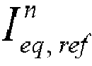

- Cell equalization method, according to claim 1(iii), characterized by the fact that the dependent (slave) equalization control algorithm with adjustable current, which is activated when NDflag == 1 is satisfied according to claims 2 and 4, and is implemented using the technique of Genetic Algorithms (GA), determines the equalization current for each cell of the segment (let's say of segment j) by minimizing the cost function


- Cell equalization method, according to claims 1(iii), 2, and 8, characterized by the fact that the


- Cell equalization method, according to claims 1(iv), 2, and 5, characterized by the fact that the dependent (slave) control algorithm of cell parameter estimation, specifically the impedance and the state-of-health (SoH) of each cell, is implemented using the EIS technique, and it determines the array of internal resistance values of the N cells in the j-segment with respect to their state-of-charge (SoC) and temperature Tc , i.e.


Applications Claiming Priority (1)
| Application Number | Priority Date | Filing Date | Title |
|---|---|---|---|
| GR20230100322A GR1010713B (en) | 2023-04-12 | 2023-04-12 | Method for equalization current regulation and energy support of battery cells |
Publications (1)
| Publication Number | Publication Date |
|---|---|
| EP4459831A1 true EP4459831A1 (en) | 2024-11-06 |
Family
ID=88068405
Family Applications (1)
| Application Number | Title | Priority Date | Filing Date |
|---|---|---|---|
| EP24169562.6A Pending EP4459831A1 (en) | 2023-04-12 | 2024-04-10 | Method for equalization current regulation and energy support of battery cells |
Country Status (3)
| Country | Link |
|---|---|
| US (1) | US20240343161A1 (en) |
| EP (1) | EP4459831A1 (en) |
| GR (1) | GR1010713B (en) |
Families Citing this family (5)
| Publication number | Priority date | Publication date | Assignee | Title |
|---|---|---|---|---|
| US12397679B2 (en) * | 2023-02-15 | 2025-08-26 | GM Global Technology Operations LLC | Optimal control strategy for a distributed low voltage system with bidirectional direct current converters |
| CN119247193B (en) * | 2024-11-22 | 2025-08-05 | 浙江大学 | A fuel cell health assessment method based on multi-impedance measurement |
| CN119199603B (en) * | 2024-11-26 | 2025-05-02 | 西安麦格米特电气有限公司 | Detection circuit, battery cell voltage compensation method and energy storage system |
| CN119995089B (en) * | 2025-01-21 | 2026-03-31 | 华中科技大学 | A battery active equalization and battery impedance spectrum detection system and method |
| CN119716575B (en) * | 2025-02-26 | 2025-05-13 | 北京索科曼正卓智能电气有限公司 | Lithium battery management method and device supporting new and old PACK mixed use |
Citations (27)
| Publication number | Priority date | Publication date | Assignee | Title |
|---|---|---|---|---|
| WO2006057468A1 (en) | 2004-11-29 | 2006-06-01 | Lg Chem, Ltd. | Method and system for battery state and parameter estimation |
| CN103023107A (en) | 2012-12-11 | 2013-04-03 | 上海大学 | Novel lithium battery pack lossless equalization circuit |
| CN103532193A (en) | 2013-10-16 | 2014-01-22 | 中国人民解放军海军工程大学 | Bidirectional converter-based battery-equalizing system and method for controlling battery equalization |
| US20140117938A1 (en) * | 2012-10-25 | 2014-05-01 | IFP Energies Nouvelles | Battery balancing converter comprising diagnostic means |
| CN103795123A (en) | 2014-02-19 | 2014-05-14 | 成都芝田高分子材料有限公司 | Intelligent battery management system based on supercapacitor active equalization |
| CN105322560A (en) | 2015-11-30 | 2016-02-10 | 华南理工大学 | Novel rapid self-equalization circuit of hybrid energy storage system |
| CN105656142A (en) | 2016-03-10 | 2016-06-08 | 北京航空航天大学 | Charge and discharge active equalization circuit of lithium-ion power battery pack |
| US20160187427A1 (en) | 2014-12-29 | 2016-06-30 | Samsung Electronics Co., Ltd. | Method and apparatus for estimating current |
| US20170214252A1 (en) | 2016-01-15 | 2017-07-27 | Mcmaster University | Energy storage balancing system |
| CN206422545U (en) | 2016-11-30 | 2017-08-18 | 华南理工大学 | A kind of hybrid energy storage system of electric automobile with voltage balancing function |
| KR101827961B1 (en) | 2017-02-28 | 2018-02-13 | 포항공과대학교 산학협력단 | Balancing circuit for hybrid battery pack using flyback transformer |
| EP3333008A1 (en) | 2016-12-12 | 2018-06-13 | Honeywell International Inc. | Adaptive balancing for battery management |
| CN109428361A (en) | 2017-09-02 | 2019-03-05 | 周宝林 | A kind of real-time battery equalizer of transfer type with bi-directional synchronization rectification function |
| US20190195956A1 (en) | 2017-12-21 | 2019-06-27 | Samsung Electronics Co., Ltd. | Battery monitoring method and apparatus detecting charge balance of battery |
| CN110797959A (en) | 2019-10-23 | 2020-02-14 | 中国电力科学研究院有限公司 | Control method and device for storage battery-super capacitor hybrid energy storage converter |
| CN110808627A (en) | 2019-11-19 | 2020-02-18 | 上海豫源电力科技有限公司 | Super capacitor hybrid lithium battery energy storage control method based on coordination |
| KR102111412B1 (en) | 2018-12-26 | 2020-05-15 | 한국기술교육대학교 산학협력단 | Hybrid battery management system |
| US20200244074A1 (en) | 2016-10-05 | 2020-07-30 | Samsung Electronics Co., Ltd. | Method and apparatus with battery charging control |
| US20200287395A1 (en) | 2019-03-07 | 2020-09-10 | Bby Solutions, Inc. | Supplemental Capacitor Based Battery Charging System |
| KR102201988B1 (en) | 2020-06-17 | 2021-01-12 | 주식회사 나산전기산업 | Battery management system for managing battery using charge-discharge characteristics of battery |
| CN112486020A (en) | 2020-12-01 | 2021-03-12 | 中国科学技术大学 | Hybrid energy storage system power distribution system and method based on adaptive model predictive control |
| US20210159710A1 (en) * | 2018-04-25 | 2021-05-27 | Sanyo Electric Co., Ltd. | Management device and power supply system |
| US20210333328A1 (en) * | 2019-01-04 | 2021-10-28 | Rejoule Incorporated | Apparatus and method for characterizing and managing stacked energy storage cells |
| WO2021256638A1 (en) | 2020-06-17 | 2021-12-23 | 주식회사 나산전기산업 | Ess system for storing electric energy in battery by using charging or discharging characteristic of battery |
| US20220224129A1 (en) | 2020-06-02 | 2022-07-14 | Inventus Power, Inc. | Battery Pack Charge Cell Balancing |
| GR1010317B (en) | 2021-09-15 | 2022-10-05 | Αριστοτελειο Πανεπιστημιο Θεσσαλονικης-Ειδικος Λογαριασμος Κονδυλιων Ερευνας, | Hybrid energy storage system for batteries and supercapacitors |
| EP4102239A1 (en) | 2020-11-05 | 2022-12-14 | LG Energy Solution, Ltd. | Battery management device and method |
-
2023
- 2023-04-12 GR GR20230100322A patent/GR1010713B/en active IP Right Grant
-
2024
- 2024-04-09 US US18/629,976 patent/US20240343161A1/en active Pending
- 2024-04-10 EP EP24169562.6A patent/EP4459831A1/en active Pending
Patent Citations (27)
| Publication number | Priority date | Publication date | Assignee | Title |
|---|---|---|---|---|
| WO2006057468A1 (en) | 2004-11-29 | 2006-06-01 | Lg Chem, Ltd. | Method and system for battery state and parameter estimation |
| US20140117938A1 (en) * | 2012-10-25 | 2014-05-01 | IFP Energies Nouvelles | Battery balancing converter comprising diagnostic means |
| CN103023107A (en) | 2012-12-11 | 2013-04-03 | 上海大学 | Novel lithium battery pack lossless equalization circuit |
| CN103532193A (en) | 2013-10-16 | 2014-01-22 | 中国人民解放军海军工程大学 | Bidirectional converter-based battery-equalizing system and method for controlling battery equalization |
| CN103795123A (en) | 2014-02-19 | 2014-05-14 | 成都芝田高分子材料有限公司 | Intelligent battery management system based on supercapacitor active equalization |
| US20160187427A1 (en) | 2014-12-29 | 2016-06-30 | Samsung Electronics Co., Ltd. | Method and apparatus for estimating current |
| CN105322560A (en) | 2015-11-30 | 2016-02-10 | 华南理工大学 | Novel rapid self-equalization circuit of hybrid energy storage system |
| US20170214252A1 (en) | 2016-01-15 | 2017-07-27 | Mcmaster University | Energy storage balancing system |
| CN105656142A (en) | 2016-03-10 | 2016-06-08 | 北京航空航天大学 | Charge and discharge active equalization circuit of lithium-ion power battery pack |
| US20200244074A1 (en) | 2016-10-05 | 2020-07-30 | Samsung Electronics Co., Ltd. | Method and apparatus with battery charging control |
| CN206422545U (en) | 2016-11-30 | 2017-08-18 | 华南理工大学 | A kind of hybrid energy storage system of electric automobile with voltage balancing function |
| EP3333008A1 (en) | 2016-12-12 | 2018-06-13 | Honeywell International Inc. | Adaptive balancing for battery management |
| KR101827961B1 (en) | 2017-02-28 | 2018-02-13 | 포항공과대학교 산학협력단 | Balancing circuit for hybrid battery pack using flyback transformer |
| CN109428361A (en) | 2017-09-02 | 2019-03-05 | 周宝林 | A kind of real-time battery equalizer of transfer type with bi-directional synchronization rectification function |
| US20190195956A1 (en) | 2017-12-21 | 2019-06-27 | Samsung Electronics Co., Ltd. | Battery monitoring method and apparatus detecting charge balance of battery |
| US20210159710A1 (en) * | 2018-04-25 | 2021-05-27 | Sanyo Electric Co., Ltd. | Management device and power supply system |
| KR102111412B1 (en) | 2018-12-26 | 2020-05-15 | 한국기술교육대학교 산학협력단 | Hybrid battery management system |
| US20210333328A1 (en) * | 2019-01-04 | 2021-10-28 | Rejoule Incorporated | Apparatus and method for characterizing and managing stacked energy storage cells |
| US20200287395A1 (en) | 2019-03-07 | 2020-09-10 | Bby Solutions, Inc. | Supplemental Capacitor Based Battery Charging System |
| CN110797959A (en) | 2019-10-23 | 2020-02-14 | 中国电力科学研究院有限公司 | Control method and device for storage battery-super capacitor hybrid energy storage converter |
| CN110808627A (en) | 2019-11-19 | 2020-02-18 | 上海豫源电力科技有限公司 | Super capacitor hybrid lithium battery energy storage control method based on coordination |
| US20220224129A1 (en) | 2020-06-02 | 2022-07-14 | Inventus Power, Inc. | Battery Pack Charge Cell Balancing |
| WO2021256638A1 (en) | 2020-06-17 | 2021-12-23 | 주식회사 나산전기산업 | Ess system for storing electric energy in battery by using charging or discharging characteristic of battery |
| KR102201988B1 (en) | 2020-06-17 | 2021-01-12 | 주식회사 나산전기산업 | Battery management system for managing battery using charge-discharge characteristics of battery |
| EP4102239A1 (en) | 2020-11-05 | 2022-12-14 | LG Energy Solution, Ltd. | Battery management device and method |
| CN112486020A (en) | 2020-12-01 | 2021-03-12 | 中国科学技术大学 | Hybrid energy storage system power distribution system and method based on adaptive model predictive control |
| GR1010317B (en) | 2021-09-15 | 2022-10-05 | Αριστοτελειο Πανεπιστημιο Θεσσαλονικης-Ειδικος Λογαριασμος Κονδυλιων Ερευνας, | Hybrid energy storage system for batteries and supercapacitors |
Non-Patent Citations (17)
| Title |
|---|
| F. S. J. HOEKSTRAH. J. BERGVELDM. C. F. DONKERS: "Optimal Control of Active Cell Balancing: Extending the Range and Useful Lifetime of a Battery Pack", IEEE TRANSACTIONS ON CONTROL SYSTEMS TECHNOLOGY, vol. 30, no. 6, 2022, pages 2759 - 2766, XP011924247, DOI: 10.1109/TCST.2022.3161764 |
| H. ZHANGY. WANGH. QIJ. ZHANG: "Active Battery Equalization Method Based on Redundant Battery for Electric Vehicles", IEEE TRANS VEHICULAR TECHNOLOGY, vol. 68, no. 8, 2019, pages 7531 - 7543, XP011739687, DOI: 10.1109/TVT.2019.2925742 |
| K.-M. LEES.-W. LEEY.-G. CHOIB. KANG: "Active Balancing of Li-Ion Battery Cells Using Transformer as Energy Carrier", IEEE TRANS. IND. ELECTRON., vol. 64, no. 2, February 2017 (2017-02-01), pages 1251 - 1257, XP011638671, DOI: 10.1109/TIE.2016.2611481 |
| M. EINHORN ET AL.: "A Current Equalization Method for Serially Connected Battery Cells Using a Single Power Converter for Each Cell", IEEE TRANS VEH. TECHNOL, vol. 60, no. 9, 2011, pages 4227 - 4237, XP011388446, DOI: 10.1109/TVT.2011.2168988 |
| M. KAUERS. NARAYANASWAMYS. STEINHORSTS. CHAKRABORTY: "Rapid Analysis of Active Cell Balancing Circuits", IEEE TRANS. COMPUTER-AIDED DESIGN OF INTEGRATED CIRCUITS AND SYSTEMS, vol. 36, no. 4, April 2017 (2017-04-01), pages 694 - 698, XP011643078, DOI: 10.1109/TCAD.2016.2597224 |
| N. JABBOURE. TSIOUMASM. KOSEOGLOUC. MADEMLIS: "Highly Reliable Monitoring and Equalization in a Hybrid Energy Storage System with Batteries and Supercapacitors for Electric Motor", IEEE INTERNATIONAL CONFERENCE SPEC'2018, SINGAPORE |
| N. JABBOURE. TSIOUMASN. KARAKASISC. MADEMLIS: "Improved Monitoring and Battery Equalizer Control Scheme for Electric Vehicle Applications", IEEE INTERNATIONAL CONFERENCE SDEMPED'2017, TINOS, GREECE |
| S. JINLEIL. WEIT. CHUANYUW. TIANRUJ. TAOT. YONG: "A Novel Active Equalization Method for Series-Connected Battery Packs Based on Clustering Analysis With Genetic Algorithm", IEEE TRANS POWER ELECTRON, vol. 36, no. 7, 2021, pages 7853 - 7865, XP011843143, DOI: 10.1109/TPEL.2021.3049166 |
| T. HARTLEYI. HUSAIN: "A Battery Management System Using an Active Charge Equalization Technique Based on a DC/DC Converter Topology", IEEE TRANS. IND. APPL., vol. 49, no. 6, December 2013 (2013-12-01), pages 2720 - 2729 |
| T. STUARTW. ZHU: "Fast equalization for large lithium-ion batteries", IEEE TRANS. AEROSP. ELECTRON. SYSTEM, vol. 24, no. 7, 27 July 2009 (2009-07-27) |
| W. DIAON. XUEV. BHATTACHARJEEJ. JIANGO. KARABASOGLUM. PECHT: "Active battery cell equalization based on residual available energy maximization", APPL ENERGY, vol. 210, 2018, pages 690 - 698, XP085303945, DOI: 10.1016/j.apenergy.2017.07.137 |
| Y. SHANGB. XIAFEI LUC. ZHANGN. CUIC. MI: "A Switched-Coupling-Capacitor Equalizer for Series-Connected Battery Strings", IEEE TRANS. POWER ELECTRON., vol. 32, no. 10, December 2016 (2016-12-01), pages 7694 - 7706 |
| Y. YUANMAOK. W. E. CHENGY. P. B. YEUNG: "Zero-current switching switched-capacitor zero-voltage-gap automatic equalization system for series battery string", IEEE TRANS. POWER ELECTRON., vol. 27, no. 7, July 2012 (2012-07-01), pages 3234 - 3242 |
| Y. ZHENGM. OUYANGL. LUJ. LIX. HANL. XU: "Online equalization for Lithium-Ion battery packs based on charging cell voltages: Part 2. fuzzy logic equalization", J. POWER SOURCES, vol. 247, February 2014 (2014-02-01), pages 460 - 466, XP028760279, DOI: 10.1016/j.jpowsour.2013.09.012 |
| Y.-X. WANGH. ZHONGJ. LIW. ZHANG: "Adaptive estimation-based hierarchical model predictive control methodology for battery active equalization topologies: Part I-Balancing strategy", J ENERGY STORAGE, vol. 45, 2022, pages 103235 |
| Z. WEIF. PENGH. WANG: "An LCC-Based String-to-Cell Battery Equalizer With Simplified Constant Current Control", IEEE TRANS POWER ELECTRON, vol. 37, no. 2, 2022, pages 1816 - 1827, XP011883072, DOI: 10.1109/TPEL.2021.3102627 |
| Z. WEIH. WANGY. LUD. SHUG. NINGM. FU: "Bidirectional Constant Current String-to-Cell Battery Equalizer Based on L2C3 Resonant Topology", IEEE TRANS POWER ELECTRON, vol. 38, no. 1, 2023, pages 666 - 677, XP011921979, DOI: 10.1109/TPEL.2022.3205440 |
Also Published As
| Publication number | Publication date |
|---|---|
| GR1010713B (en) | 2024-06-25 |
| US20240343161A1 (en) | 2024-10-17 |
Similar Documents
| Publication | Publication Date | Title |
|---|---|---|
| EP4459831A1 (en) | Method for equalization current regulation and energy support of battery cells | |
| US10910858B2 (en) | Systems and methods for series battery charging | |
| Zhang et al. | Active battery equalization method based on redundant battery for electric vehicles | |
| CN102959827B (en) | Electric storage device control circuit and electric storage device | |
| US8581557B2 (en) | Direct-current power source apparatus | |
| CN102445665B (en) | Battery pack capacity learning algorithm | |
| US20250309669A1 (en) | Supercapacitor based energy storage device | |
| KR102151652B1 (en) | Using Cuk Converter topology Li-ion battery cell balancing strategy | |
| Yan et al. | Fuzzy control for battery equalization based on state of charge | |
| Yildirim et al. | Evaluation and comparison of battery cell balancing methods | |
| Zhang et al. | Hybrid balancing in a modular battery management system for electric-drive vehicles | |
| CN117378116A (en) | Circuit device for controlling output voltage | |
| Abronzini et al. | Optimal modular bms for high performances nmc battery pack | |
| Manjunath et al. | A modularized two-stage active cell balancing circuit for series connected Li-ion battery packs | |
| Alam et al. | Power management scheme based on aging factor of battery storage systems for electric vehicles | |
| Chowdhury et al. | An integrated control strategy for state of charge balancing with output voltage control of a series connected battery management system | |
| CN114938049A (en) | Method and system for charging and discharging balance protection detection management of battery pack | |
| Valchev et al. | Improvement on LiFePO4 cell balancing algorithm | |
| Sun et al. | Active battery equalization system based on extended kalman filter and dc-dc bidirectional flyback converter | |
| Moshirvaziri | Lithium-ion battery modeling for electric vehicles and regenerative cell testing platform | |
| Siddeshkumar et al. | Advanced Optimized Active Cell Balancing with Efficient Power Electronics Algorithms for Superior Battery Performance in Electric Vehicle | |
| Duan et al. | An electric vehicle battery modular balancing system based on solar energy harvesting | |
| Koseoglou et al. | An improved active li-ion battery equalization scheme for enhancing the performance of a nearly zero energy building and electric vehicle microgrid | |
| Dehghani et al. | Decentralized Battery Charger with High Precision Active Equalization Capability | |
| Jabbour et al. | An enhanced equalization and energy support algorithm for lithium-ion battery storage systems in electric motor drives |
Legal Events
| Date | Code | Title | Description |
|---|---|---|---|
| PUAI | Public reference made under article 153(3) epc to a published international application that has entered the european phase |
Free format text: ORIGINAL CODE: 0009012 |
|
| STAA | Information on the status of an ep patent application or granted ep patent |
Free format text: STATUS: REQUEST FOR EXAMINATION WAS MADE |
|
| 17P | Request for examination filed |
Effective date: 20240430 |
|
| AK | Designated contracting states |
Kind code of ref document: A1 Designated state(s): AL AT BE BG CH CY CZ DE DK EE ES FI FR GB GR HR HU IE IS IT LI LT LU LV MC ME MK MT NL NO PL PT RO RS SE SI SK SM TR |
|
| RIN1 | Information on inventor provided before grant (corrected) |
Inventor name: TSIOUMAS, EVANGELOS Inventor name: JABBOUR, NIKOLAS Inventor name: MADEMLIS, CHRISTOS |