EP4459808A1 - Track adapter, track and electrical system - Google Patents
Track adapter, track and electrical system Download PDFInfo
- Publication number
- EP4459808A1 EP4459808A1 EP22914556.0A EP22914556A EP4459808A1 EP 4459808 A1 EP4459808 A1 EP 4459808A1 EP 22914556 A EP22914556 A EP 22914556A EP 4459808 A1 EP4459808 A1 EP 4459808A1
- Authority
- EP
- European Patent Office
- Prior art keywords
- elastic
- track
- assembly
- side cover
- sliding
- Prior art date
- Legal status (The legal status is an assumption and is not a legal conclusion. Google has not performed a legal analysis and makes no representation as to the accuracy of the status listed.)
- Pending
Links
Images









Classifications
-
- H—ELECTRICITY
- H01—ELECTRIC ELEMENTS
- H01R—ELECTRICALLY-CONDUCTIVE CONNECTIONS; STRUCTURAL ASSOCIATIONS OF A PLURALITY OF MUTUALLY-INSULATED ELECTRICAL CONNECTING ELEMENTS; COUPLING DEVICES; CURRENT COLLECTORS
- H01R25/00—Coupling parts adapted for simultaneous co-operation with two or more identical counterparts, e.g. for distributing energy to two or more circuits
- H01R25/14—Rails or bus-bars constructed so that the counterparts can be connected thereto at any point along their length
- H01R25/142—Their counterparts
-
- F—MECHANICAL ENGINEERING; LIGHTING; HEATING; WEAPONS; BLASTING
- F21—LIGHTING
- F21V—FUNCTIONAL FEATURES OR DETAILS OF LIGHTING DEVICES OR SYSTEMS THEREOF; STRUCTURAL COMBINATIONS OF LIGHTING DEVICES WITH OTHER ARTICLES, NOT OTHERWISE PROVIDED FOR
- F21V23/00—Arrangement of electric circuit elements in or on lighting devices
- F21V23/06—Arrangement of electric circuit elements in or on lighting devices the elements being coupling devices, e.g. connectors
-
- F—MECHANICAL ENGINEERING; LIGHTING; HEATING; WEAPONS; BLASTING
- F21—LIGHTING
- F21V—FUNCTIONAL FEATURES OR DETAILS OF LIGHTING DEVICES OR SYSTEMS THEREOF; STRUCTURAL COMBINATIONS OF LIGHTING DEVICES WITH OTHER ARTICLES, NOT OTHERWISE PROVIDED FOR
- F21V35/00—Candle holders
-
- H—ELECTRICITY
- H01—ELECTRIC ELEMENTS
- H01R—ELECTRICALLY-CONDUCTIVE CONNECTIONS; STRUCTURAL ASSOCIATIONS OF A PLURALITY OF MUTUALLY-INSULATED ELECTRICAL CONNECTING ELEMENTS; COUPLING DEVICES; CURRENT COLLECTORS
- H01R13/00—Details of coupling devices of the kinds covered by groups H01R12/70 or H01R24/00 - H01R33/00
- H01R13/46—Bases; Cases
- H01R13/502—Bases; Cases composed of different pieces
- H01R13/506—Bases; Cases composed of different pieces assembled by snap action of the parts
-
- H—ELECTRICITY
- H01—ELECTRIC ELEMENTS
- H01R—ELECTRICALLY-CONDUCTIVE CONNECTIONS; STRUCTURAL ASSOCIATIONS OF A PLURALITY OF MUTUALLY-INSULATED ELECTRICAL CONNECTING ELEMENTS; COUPLING DEVICES; CURRENT COLLECTORS
- H01R13/00—Details of coupling devices of the kinds covered by groups H01R12/70 or H01R24/00 - H01R33/00
- H01R13/62—Means for facilitating engagement or disengagement of coupling parts or for holding them in engagement
- H01R13/6205—Two-part coupling devices held in engagement by a magnet
-
- H—ELECTRICITY
- H01—ELECTRIC ELEMENTS
- H01R—ELECTRICALLY-CONDUCTIVE CONNECTIONS; STRUCTURAL ASSOCIATIONS OF A PLURALITY OF MUTUALLY-INSULATED ELECTRICAL CONNECTING ELEMENTS; COUPLING DEVICES; CURRENT COLLECTORS
- H01R13/00—Details of coupling devices of the kinds covered by groups H01R12/70 or H01R24/00 - H01R33/00
- H01R13/62—Means for facilitating engagement or disengagement of coupling parts or for holding them in engagement
- H01R13/627—Snap or like fastening
- H01R13/6271—Latching means integral with the housing
- H01R13/6273—Latching means integral with the housing comprising two latching arms
-
- H—ELECTRICITY
- H01—ELECTRIC ELEMENTS
- H01R—ELECTRICALLY-CONDUCTIVE CONNECTIONS; STRUCTURAL ASSOCIATIONS OF A PLURALITY OF MUTUALLY-INSULATED ELECTRICAL CONNECTING ELEMENTS; COUPLING DEVICES; CURRENT COLLECTORS
- H01R25/00—Coupling parts adapted for simultaneous co-operation with two or more identical counterparts, e.g. for distributing energy to two or more circuits
- H01R25/14—Rails or bus-bars constructed so that the counterparts can be connected thereto at any point along their length
- H01R25/145—Details, e.g. end pieces or joints
Definitions
- the present application relates to the technical field of lighting technology, especially to a track adapter, track, and electrical system.
- Track lamps are mainly composed of a track (a conductive track) fixed on a ceiling or wall, and various lamps capable of sliding along the tracks, which can be spotlights, line lamps, or the like.
- Track adapters fitted with the tracks are usually hidden within the tracks, which increases the difficulty for installing the track lamps.
- most of current track lamps on the market are magnetic track lamps, in which the lamp body is directly connected to the track by magnetic force, which is convenient for rapidly installing.
- using magnetic connection alone does not have a strong stability. If the magnetic attraction between magnetic pieces disappears, or the light-emitting module is relatively heavy, the track adapter may be likely to be separated from the track, resulting in safety risk of track lamp falling.
- An object of the present application is to provide a track adapter which is simple and convenient to install, and has a high stability in connection with the track.
- the present application provides a track adapter for coupling an electrical equipment to a track in a first direction, comprising: a shell and a sliding assembly slidably connected to the shell, the sliding assembly comprises a sliding side cover located at an end of the shell and an elastic assembly located inside the shell and fixedly connected to the sliding side cover, the elastic assembly comprises two symmetrically disposed elastic arms and elastic blocks located at an end of each of the elastic arms near the sliding side cover, a side wall of the shell is provided with elastic block sliding grooves at positions corresponding to the elastic blocks, two guide ribs in cooperation with the elastic arms are further disposed inside the shell, a giving-way channel for giving way to the elastic assembly is formed between the two guide ribs, and the elastic assembly cooperates with the guide ribs to drive the elastic blocks to slide out of or into the elastic block sliding grooves.
- the two guide ribs are disposed within the shell in a third direction, respectively, and form the giving-way channel extending in a second direction
- the guide ribs cooperate with the elastic arms and are configured so that when the sliding side cover applies a pushing force to the elastic assembly in the second direction, the elastic assembly at least partially enters the giving-way channel in the second direction, while the elastic arms are blocked by the guide ribs and pushed to move towards each other in the third direction to drive the elastic blocks to slide out of the elastic block sliding grooves; and after the pushing force applied by the sliding side cover disappears, the elastic arms are driven by an elastic restoring force to move away from each other in the third direction, and the elastic assembly is guided by the guide ribs to move out of the giving-way channel in a direction opposite to a pushing direction, while the elastic arms drive the elastic blocks to move away from each other in the third direction to slide into the elastic block sliding grooves, and the first direction, the second direction, and the third direction are perpendicular to each other.
- each of the guide ribs comprises a first wall parallel to the sliding side cover, a second wall extending in a direction away from the sliding side cover, and an arc wall connecting the first wall and the second wall, the arc wall cooperates with the elastic arms so that the two elastic arms are close to or away from each other.
- the sliding assembly further comprises a connection part connecting the sliding side cover and the elastic assembly, the two elastic arms are symmetrically disposed along the connection part, and each of the elastic arms comprises a first end away from the sliding side cover, a second end near the sliding side cover, and a third end connecting two second ends and fixedly connected to the connection part.
- an inner side wall of the second end connected to the third end is depressed in a direction away from the sliding side cover to form a deformation point, the deformation point is configured to guide the elastic assembly to deform with the deformation point as a designated point.
- the elastic blocks are disposed at the first ends of the elastic arms, and a distance between the two first ends is greater than a distance between the two second ends.
- connection part near the elastic assembly extends in a direction away from the elastic assembly to form two projecting portion, a guide gap is formed between the two projecting portions, and the shell is provided with a guide protrusion fitted with the guide gap.
- the sliding side cover, the connection part, and the elastic assembly are formed integrally.
- a side of the elastic blocks near the elastic block sliding grooves is provided with an inclined plane inclining from an end near the elastic block sliding grooves to an end near the sliding side cover.
- the side wall is further provided with a snap part disposed at an end away from the elastic block sliding grooves and comprising a fixed end and a free end disposed in turn and connected with each other, a side of the free end away from the fixed end extends in a direction away from the shell to form a stop projection.
- the stop projection comprises a guiding slope and an abutting slope disposed adj acent to each other, the guiding slope is disposed on a side of the stop projection near the fixed end and inclinedly extends downwards from an end near the fixed end to an end away from the fixed end; and the abutting slope is disposed on a side of the stop projection near the elastic block sliding grooves and inclinedly extends from an end near the elastic block sliding grooves to an end away from the elastic block sliding grooves.
- the track adapter further comprises contact elastic pieces, the contact elastic pieces are disposed within the shell, at least partially exposed outside the side wall, and configured to be electrically connected to a conductive part within the track.
- the second purpose of this application is to provide a track that is connected in conjunction with the aforementioned track adapter.
- the present application provides a track, the track is configured to be mechanically and electrically connected to the track adapter above; the track is provided with an anti-detachment boss extending in the third direction, the anti-detachment boss is configured to support the elastic assembly and the snap part of the track adapter.
- the third purpose of this application is to provide an electrical system comprising the aforementioned track adapter.
- the present application provides an electrical system, comprising a track and the track adapter above; the track is provided with an anti-detachment boss extending in the third direction, the track adapter comprises a sliding assembly, guide ribs, and a snap part, the sliding assembly comprises a sliding side cover and an elastic assembly, the sliding side cover drives the elastic assembly to cooperate with the guide ribs so that the elastic assembly is connected to or separated from the anti-detachment boss; the snap part is connected to or separated from the anti-detachment boss under an interaction between the snap part and an inner surface of the track; the inner surface of the track is provided with an conductive part extending in a length direction of the track, an outer surface of the track adapter is provided with a contact elastic piece, and the conductive part is electrically connected to the contact elastic piece.
- the track includes a receiving space, the track adapter is at least partially received in the receiving space in the first direction, the track comprises a first magnetic piece disposed at the top of the receiving space, the track adapter comprises a second magnetic piece disposed at the top of the track adapter, and the first magnetic piece is in magnetic attraction fit with the second magnetic piece in the first direction.
- the track adapter of the present application achieves rapid installation and disassembly of the track adapter and the track while the connection stability of the track adapter and the track is increased by disposing two guide ribs in cooperation with the elastic arms and forming a giving-way channel for giving way to the elastic assembly between the two guide ribs so that the guide ribs give a deformation force to the elastic arms when the elastic assembly moves relative to the guide ribs, so as to drive the elastic blocks to slide out of or into the elastic block sliding grooves.
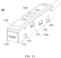
- a track adapter 100 of the first preferred embodiment of the present application is shown, which is used to couple an electrical equipment (not shown) to a track 200 in a first direction.
- the track adapter 100 comprises a shell 110, a sliding side cover 120 and an elastic assembly 130. By the cooperation of the sliding side cover 120 with the elastic assembly 130, it is achieved to rapidly install the track adapter 100 coupled with the electrical equipment to the track 200, and increase the connection stability between the track adapter 100 and the track 200.
- the track adapter 100 can be rapidly disassembled from the track 200 by the cooperation of the sliding side cover 120 with the elastic assembly 130, which is convenient and quick, and can reduce the difficulty of installation and disassembly and increase the efficiency of installation and disassembly.
- the sliding side cover 120 is slidably connected to an end of the shell 110 in a second direction perpendicular to the first direction.
- An elastic assembly 130 is fixedly connected inside the shell 110.
- the elastic assembly 130 comprises an elastic body 131 and two elastic blocks 133 disposed on two sides of the elastic body 131.
- a side wall 112 of the shell 110 is provided with two elastic block sliding grooves 1121 at positions corresponding to the two elastic blocks 133.
- the elastic assembly 130 cooperates with the sliding side cover 120, and is configured for being applied with a pushing force by the sliding side cover 120 in the second direction to drive the two elastic blocks 133 to move towards each other in a third direction, so as to slide out of the elastic block sliding grooves 1121, and move away from each other in the third direction to slide into the elastic block sliding grooves 1121 after the pushing force disappears, in which the third direction is perpendicular to both the first direction and the second direction.
- the sliding side cover 120 when the sliding side cover 120 is driven by a pushing force, the sliding side cover 120 applies a pushing force to the elastic assembly 130 in the second direction, causing the elastic assembly 130 to deform, so that the two elastic blocks 133 move towards each other in the third direction to slide out of the elastic block grooves 1121.
- the elastic blocks 133 are in retracted state, which is convenient to rapidly couple the track adapter 100 to the track 200, or disassemble the track adapter 100 from the track 200.
- the two elastic blocks 133 move away from each other in the third direction under the action of the elastic assembly 130's own elastic force to slide into the elastic block sliding grooves 1121.
- the elastic blocks 133 are in extended state, which is convenient to abut against the anti-detachment boss 230 on the track 200 extending in the third direction to increase the connection stability between the track 200 and the track adapter 100.
- the first direction is a height direction of the track 200 or the track adapter 100
- the second direction is a length direction of the track 200 or the track adapter 100
- the third direction is a width direction of the track 200 or the track adapter 100.
- the first direction, the second direction, and the third direction are perpendicular to each other.
- the switching between the extended state and the retracted state of the elastic blocks 133 can be controlled manually or automatically via a control device. That is, the movement of the sliding side cover 120 towards the elastic assembly 130 in the second direction can controlled either manually or automatically, which is not specifically limited in the embodiments of the present application.
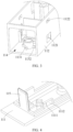
- the shell 110 comprises a top wall 111 and a bottom wall 113 extending in the length direction, a pair of side walls 112 connecting the top wall 111 and the bottom wall 113 and extending in the length direction, and two opposite ends connecting the top wall 111 and the bottom wall 113 and extending in the width direction.
- the bottom wall 113, the side walls 112, and the ends surround to form a lower groove having an installation space 114 for receiving an electrical part, and the elastic assembly 130, etc.
- the top wall 111 and the lower groove are arranged separately.
- An end of the top wall 111 towards the lower groove extends in a direction towards the lower groove to form a leg 1111.
- the leg 1111 extends in a direction towards the side wall 112 of the lower groove to form a hook 1112, and the side wall 112 of the lower groove is provided with a clamping opening 1122 in a position corresponding to the hook 1112.
- the hook 1112 cooperates with the clamping opening 1122 to fixedly connect the top wall 111 to the lower groove.
- the hook 1112 can also be disposed on the lower groove, and the clamping opening 1122 can be disposed on the leg 1111 of the top wall 111.
- the top wall 111 and the lower groove are fixedly connected in other ways, or the shell 110 can also be integrally disposed, which is not limited in the present application.
- the bottom wall 113 of the shell 110 is provided with a fixing part 1131, that is, the fixing part 1131 is disposed at the bottom of the shell 110 and configured to fixedly limit the elastic assembly 130 within the shell 110.
- the fixing part 1131 is in cylindrical shape and extends in a direction from the bottom wall 113 to the top wall 111 of the shell 110.
- the elastic body 131 of the elastic assembly 130 is sheathed on the fixing part 1131 to fixedly limit the elastic body 131 within the shell 110, preventing the elastic body 131 from moving left-and-right or front-and-back within the shell 110 driven by the sliding side cover 120 to affect the sliding of the elastic block 133 located on two sides of the elastic body 131 into or out of the elastic block sliding grooves 1121.
- booster blocks 1132 are disposed on a peripheral wall of the fixing part 1131 at positions near the bottom wall 113.
- the booster blocks 1132 are evenly disposed along the peripheral wall of the fixing part 1131, so that the elastic body 131 has a space from the bottom wall 113, and thus the elastic blocks 133 located on two sides of the elastic body 131 have a space from the bottom wall 113, which facilitates the elastic block 133 to slide into or out of the elastic block sliding grooves 1121.
- the elastic assembly 130 is disposed on the fixing part 1131, and comprises an elastic body 131 and elastic blocks 133 disposed on two sides of the elastic body 131.
- the elastic body 131 comprises an installation part 134 fixedly connected to the fixing part 1131, and two symmetrically disposed elastic arms 132 inclinedly extending outwards from the installation part.
- the elastic blocks 133 are disposed at ends of the elastic arms 132 away from the elastic body 131, and integrally formed with the elastic body 131 to save the article quantity and reduce the assembly difficulty.
- the elastic body 131 is a torsion spring.
- the center of the torsion spring that is, the installation part 134, is annular, the fixing part 1131 is cylindrical, and the installation part 134 is sheathed on the fixing part 1131.
- the two elastic arms 132 of the torsion spring are symmetrically disposed relative to the fixing part 1131.
- the elastic blocks 133 are formed on ends of the two elastic arms 132 away from the center of the torsion spring by molding encapsulation process to reduce the article quantity of the elastic assembly 130 and reduce the material and assembly costs.
- the two elastic arms 132 can drive the two elastic blocks 133 located at the ends of the elastic arms 132 to move towards or away from each other.
- the elastic body 131 is fixed on the fixing part 1131, when the elastic arms 132 are pushed by the two support plates 1221 of the sliding side cover 120 in the second direction, the two elastic arms 132 move towards each other, so that the two elastic blocks 133 located at the ends of the two elastic arms 132 away from the elastic body 131 are driven to move towards each other, causing the elastic blocks 133 to slide out of the elastic block sliding grooves 1121.
- the push force disappears, the deformation of the two elastic arms 132 automatically recovers.
- the two support plates 1221 of the sliding side cover 120 are driven by the elastic restoring force of the two elastic arms 132 to move in a direction away from the pushing force, so that the sliding side cover 120 returns to its initial state.
- the two elastic arms 132 thus drive the two elastic blocks 133 located at the ends of the two elastic arms 132 away from the elastic body 131 to move away from each other so that the elastic blocks 133 automatically slide into the elastic block sliding grooves 1121.
- the connection between the elastic blocks 133 and the elastic block sliding grooves 1121 is more stable.
- the elastic assembly 130 can also be other elastic components, or the elastic body 131 and the elastic blocks 133 can be separately provided and then assembled, which is not limited in the present application.
- the elastic blocks 133 are disposed away from the sliding side cover 120 relative to the elastic body 131, that is, the elastic blocks 133 are disposed away from the sliding side cover 120 relative to the fixing part 1131.
- the elastic blocks 133 move towards each other in a direction towards the fixing part 1131.
- An inclined plane 1331 is disposed on a side of the elastic block 133 near the elastic block sliding groove 1121.
- the inclined plane 1331 is inclined from an end of the elastic block near the elastic block sliding groove 1121 to an end away from the sliding side cover 120. That is, the inclined plane 1331 is disposed away from the sliding side cover 120.
- the configuration of the inclined plane1331 can also facilitate the elastic block 133 to slide into the elastic block sliding groove 1121 and to be exposed outside the shell 110, thereby facilitating to abut against the anti-detachment boss 230 on the track 200 to increase the connection stability between the track 200 and the track adapter 100.
- the length of the elastic block groove 1121 is slightly longer than the length of the elastic block 133 to provide a moving space for the elastic block 133 sliding into or out of the elastic block groove 1121, which facilitates the sliding-in or sliding-out of the elastic block 133.
- the track adapter 100 of the present application further comprises a sliding side cover 120 slidably connected to an end of the shell 110 and at least partially received within the installation space 114.
- the sliding side cover 120 is partially exposed outside the end of the shell 110 to facilitate the applying of the pushing force to the sliding side cover 120.
- the sliding side cover 120 is slidably connected to the shell 110 in the second direction to drive the elastic arms 132 of the elastic assembly 130 to deform, thereby causing the elastic block 133 to slide into or out of the elastic block sliding groove 1121.
- the sliding side cover 120 comprises a press part 121 exposed outside the shell 110 and a sliding stop part 122 received within the installation space 114, and a stop wall 123 for limiting the sliding side cover 120 located between the sliding stop part 122 and the press part 121.
- the press part 121 is exposed outside the shell 110 to facilitate the applying of the pushing force to the sliding side cover 120.
- the stop wall 123 extends in a direction from the top of the press part 121 towards the top wall 111, and is received within the installation space 114 for limiting the sliding side cover 120, so as to prevent the elastic part 130 from deformation recovery after the pushing force disappears, the sliding side cover 120 is driven by the elastic restoring force of the elastic part 130 to move in a direction away from the elastic part 130 and drops from the end of the shell 110.
- the sliding stop part 122 is received within the installation space 114, fixedly connected to the press part 121, and disposed near the fixing part 1131 relative to the press part 121, so that the press part 121 drives the sliding stop part 122 to contact the outer surfaces of the two elastic arms 132 of the elastic assembly 130 when the press part 121 is pushed, thereby causing the two elastic arms 132 to deform and drive the elastic blocks 133 to slide out of the elastic block sliding grooves 1121.
- the press part 121, the sliding stop part 122 and the stop wall 123 are integrally formed.
- the press part 121 and the sliding stop part 122 can also be provided separately, which is not limited in the present application, as long as the press part 121 and the sliding stop part 122 are fixedly connected and can drive the sliding stop part 122 to move.
- the sliding stop part 122 comprises two opposite support plates 1221 and a connection plate 1222 located above the support plates 1221 and configured to connect the support plates 1221.
- the support plates 1221 and the connection plates 1222 surround to form a receiving groove 1223, and a channel is formed between the two support plates 1221 of the receiving groove 1223, which is used to give way to the fixing part 1131 to prevent the sliding stop part 122 from colliding with the fixing part 1131 and failing to act on the elastic arms 132 of the elastic assembly 130 when the sliding stop part 122 moves towards the fixing part 1131.
- connection plate 1222 of the receiving groove 1223 can limit the installation part 134 of the elastic assembly 130 in the first direction to prevent the elastic arms 132 of the elastic assembly 130 from being pushed too much to cause the detachment of the installation part 134 from the fixing part 1131.
- the distance between the two support plates 1221 of the sliding stop part 122 is greater than the width of the fixing part 1131, and less than the distance between the two elastic arms 132 in free state.
- the sliding stop part 122 can not only avoid the fixing part 1131, but also interact with the outer surface of the elastic arms 132 of the elastic assembly 130, so that the fixing part 1131 can be received within the receiving groove 1223 during the movement of the sliding stop part 122 towards the elastic assembly 130 to prevent a collision, and meanwhile the elastic assembly 130 is limited in the first direction.
- the two support plates 1221 of the sliding stop part 122 cooperate with the two elastic arms 132 of the elastic assembly 130 to drive the elastic blocks 133 to slide out or into the elastic block sliding grooves 1121.
- the sliding stop part 122 moves in the second direction, and the installation part 134 of the elastic assembly 130 is received in the receiving groove 1223.
- the two support plates 1221 move in the second direction, and pushes the outer surfaces of the two elastic arms 132, thereby driving the two elastic arms 132 to move towards each other in the third direction, and drive the elastic blocks 133 located at the ends of the elastic arms 132 away from the sliding side cover 120 to move towards each other in the third direction to slide out of the elastic block sliding grooves 1121.
- the elastic assembly 130 deforms under the action of the push force.
- connection plate 1222 In the first direction, the plane where the lowest point of the connection plate 1222 is located is higher than the plane where the highest point of the fixing part 1131 is located, that is, in the first direction, the connection plate 1222 is located above the fixing part 1131.
- the connection plate 1222 covers above the fixing part 1131 so that the installation part 134 of the elastic part 130 is fixedly limited on the fixing part 1131 to prevent the installation part 134 of the elastic assembly 130 from falling off the fixing part 1131.
- the sliding stop part 122 After the pushing force disappears, under the action of elastic restoring force of the two elastic arms 132, the sliding stop part 122 is driven to move reversely in the second direction.
- the two support plates 1221 of the sliding stop part 122 are separated from the two elastic arms 132, and move in a direction away from the pushing force, so that the sliding side cover 120 returns to its initial state.
- the two elastic arms 132 are separated from the two support plates 1221, and the two elastic arms 132 return to their original states and drive the two elastic blocks 133 to slide into the elastic block sliding grooves 1121.
- the shell 110 further comprises a limiting rib 115.
- the limiting rib 115 is configured to limit the moving distance of the sliding side cover 120 in the second direction to prevent the sliding side cover 120 from being pushed too much to completely enter the shell 110, which is not convenient for the restoration and repression of the sliding side cover 120.
- the limiting rib 115 is disposed away from the sliding side cover 120 relative to the fixing part 1131 to give a moving distance to the sliding side cover 120, facilitating the contact between the sliding stop part 122 of the sliding side cover 120 and the elastic arms 132 of the elastic assembly 130.
- the limiting rib 115 is plate-like, which is disposed at the top wall 111 of the shell 110 and extends from the top wall 111 to the bottom wall 113.
- the limiting rib 115 can also be disposed on the bottom wall 113 and extends in a direction from the bottom wall 113 to the top wall 111, which is not limited in the present application.
- the side wall 112 of the shell 110 of the track adapter 100 is further provided with a snap part 140 disposed at an end away from the elastic block sliding grooves 1121.
- the snap part 140 comprises a fixed end 141 and a free end 142 that are sequentially arranged and connected. A side of the free end 142 away from the fixed end 141 extends in a direction away from the shell 110 to form a stop projection 143.
- the stop projection 143 is used to stably connect the track adapter 100 to the track 200.
- the two side walls 112 of the shell 110 are provided with the elastic block sliding grooves 1121 and the snap parts 140.
- the elastic blocks 133 together with the stop projection 143 form four auxiliary support points to secure the track adapter 100 to the track 200.
- the snap part 140 is disposed at an end away from the elastic block sliding grooves 1121 so that the four auxiliary support points are located at four corners of the track adapter 100 to secure the track adapter 100 on the track 200 more firmly.
- the stop projection 143 disposed on the free end 142 can deform towards the inside of the shell 110 relative to the fixed end 141 to release the connection between the stop projection 143 and the track 200 or facilitate the connection of the stop projection 143 to the anti-detachment boss 230 of the track 200.
- the stop projection 143 further comprises a guiding slope 1431 disposed on a side of the stop projection 143 near the fixed end 141. That is, the guiding slope 1431 is disposed on the stop projection 143, and inclinedly extends downwards from the end near the fixed end 141 to the end away from the fixed end 141.
- the guiding slope 1431 can guide the forced direction of the stop projection 143 to facilitate the stop projection 143 to clip into the anti-detachment boss 230 of the track 200.
- the stop projection 143 further comprises an abutting slope 1432, which is disposed on a side of the stop projection 143 near the elastic block sliding grooves 1121, and inclinedly extends from the end near the elastic block sliding grooves 1121 to the end away from the elastic block sliding grooves 1121. That is, the abutting slope 1432 is located on the side of the stop projection 143 near the elastic block sliding grooves 1121, and adjacent to the guiding slope 1431.
- the track adapter 100 further comprises contact elastic pieces 150, which are disposed within the installation space 114 of the shell 110, and at least partially exposed outside the side wall 112 of the shell 110 to be electrically connected to the conductive part 240 on the track 200 so that the track adapter 100 and the track 200 are electrically connected to each other while mechanically connected to each other.
- the contact elastic piece 150 comprises a pair of power supply elastic pieces 151 and a pair of signal elastic pieces 152. Both the power supply elastic pieces 151 and the signal elastic pieces 152 are disposed within the installation space 114 of the shell 110 and exposed outside the side 112 of the shell 110, and the power supply elastic pieces 151 are configured to be in contact fit with the power supply conductive part 241 of the track 200, and the signal elastic pieces 152 are configured to be in contact fit with the signal conductive part 242 of the track 200. In this embodiment, both the pair of power supply elastic pieces 151 and the pair of signal elastic pieces 152 are symmetrically disposed along the central axis in the length direction of the shell 110.
- one power supply elastic piece 151 and one signal elastic piece 152 are exposed on each side 112 of the shell 110, while the power supply elastic piece 151 and the signal elastic piece 152 are staggered up and down on the same side wall 112 of the shell 110.
- the pair of power supply elastic pieces or the pair of signal elastic pieces 152 can also be disposed on the same side wall 112, which is not limited in the present application.
- the contact elastic piece 150 comprises four power supply elastic pieces 151 comprising two positive electrodes and two negative electrodes, and correspondingly, the track 200 comprises four power supply conductive parts 241, so that a dual electrical loop is formed between the adapter 100 and the track 200 to meet the requirement for independently controlling the dual outputs in market-trending dimming and toning products. It can also be made to independently control each loop in a four-wire three-loop circuit, or it can also utilize a combination in which the power elastic pieces 151 are increased or decreased in accordance with the requirement of practical loops.
- the power supply elastic pieces 151 and the signal elastic pieces 152 can have certain elasticity.
- the power supply conductive part 241 applies an acting force to the power supply elastic piece 151, and the restoring force of the power supply elastic piece 151 allows the power supply elastic piece 151 to be in contact fit with the power supply conducive part 241 better, thereby achieving a reliable electrical connection.
- the signal elastic piece 152 cooperates by contact with the signal conductive part 242
- the signal conductive part 242 applies an acting force to the signal elastic piece 152
- the restoring force of the signal elastic piece 152 allows the signal elastic piece 152 to be in contact fit with the signal conductive part 242 better, thereby achieving a reliable signal connection.
- the power supply elastic piece 151 and the signal elastic piece 152 can have certain elasticity, so that the power supply elastic pieces 151 and the signal elastic pieces 152 are always in contact fit with the power supply conductive part 241 and the signal conductive part 242 of the track 200 when the track adapter 100 slides in the track 200, and will not affect the power supply and signal transmission of the electrical system 300 having the track 200 and the track adapter 100.
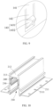
- the present application also provides a track 200 that is connected and cooperates with the track adapter 100, the track 200 is mechanically connected and electrically connected to the track adapter 100.
- the track 200 has a receiving space 210, and the track adapter 100 is at least partially located in the receiving space 210 in a first direction and is mechanically and electrically connected to the track 200.
- the track 200 is fixedly connected to an installation foundation.
- the track adapter 100 can freely slide along the track 200, so that the installation position of an electrical equipment coupled to the track adapter 100 can be moved on the track 200 as required.
- the track 200 of the present application can be an embedded track 200, a surface-mounted track 200 or a hanging track 200, which is not limited in the present application.
- the lower surface of the track 200 is fixedly connected to the installation foundation.
- the lower surface of the track 200 is provided with an installation plate 211 extending in the width direction and the length direction of the track 200.
- the installation plate 211 is provided with several installation holes 2111.
- the quantity of the installation holes 2111 is determined according to the length of the track 200, which is not limited in the present application.
- the multiple installation holes 2111 are evenly distributed in the length direction of the track 200 for fixing the track 200 onto the installation foundation.
- the track 200 of the present application is a surface-mounted track 200
- the upper surface of the track 200 is fixedly connected to the installation foundation. That is, the upper surface of the track 200 is provided with a receiving space 212 for receiving installation parts (not shown). By the installation parts disposed in the receiving space 212, the track 200 is fixedly installed on the installation foundation.
- the track 200 of the present application is a hanging track 200
- it is connected to the installation parts in the receiving space 212 of the track 200 through traction structures (not shown), such as hanging wires and rigid suspenders, so that the track 200 is fixed to the installation foundation.
- the installation foundation in the present application can be a ceiling or a wall, etc.
- the track 200 comprises a first magnetic piece 220 disposed at the top of the receiving space 210
- the track adapter 100 comprises a second magnetic piece 160 disposed at the top of the track adapter 100
- the first magnetic piece 220 is in magnetic attraction fit with the second magnetic piece 160 in the first direction to fix the track adapter 100 within the receiving space 210 of the track 200 in the first direction.
- an assembly slot 213 is provided at the top of the receiving space 210 of the track 200
- the first magnetic piece 220 is disposed in the assembly slot 213
- the second magnetic piece 160 is disposed at the top wall 111 of the track adapter 100.
- the first magnetic piece 220 is in magnetic attraction fit with the second magnetic piece 160 in the first direction to connect the track adapter 100 to the track 200, so that the electrical equipment coupled to the track adapter 100 can be installed onto the track 200, and the electrical equipment can slide along with the track adapter 100 on the track 200.
- one of the first magnetic piece 220 and the second magnetic piece 160 can be a permanent magnet, and the other can be an iron piece, and the permanent magnet and the iron piece can be in a magnetic attraction fit.
- Both of the first magnetic piece 220 and the second magnetic piece 160 can be permanent magnets, and the different magnetic poles of the two permanent magnets can be in magnetic attraction fit with each other.
- first magnetic piece 220 and the second magnetic piece 160 can also be other types of magnetic pieces, which are not specifically limited in the embodiments of the present application.
- the track 200 and the track adapter 100 form a mechanical connection via the magnetic connection.
- the track 200 and the track adapter 100 can also directly form a mechanical connection in a manner, such as clamping or the like, or the track 200 and the track adapter 100 can be both magnetically and mechanically connected, which is not limited in the present application.
- the track 200 of the present application is further provided with an anti-detachment boss 230 extending in the third direction, which is configured to support the elastic assembly 130 and the snap part 140 of the track adapter 100.
- the elastic assembly 130, the snap part 140, and the anti-detachment boss 230 are connected to each other and are in an interference fit.
- the connection between the track adapter 100 and the track 200 or the connection between the electrical equipment coupled to the track adapter 100 and the track 200 is more stable, thereby improving the safety of the electrical system 300 having the track 200 and the track adapter 100.
- the track adapter 100 and the track 200 can also not include other mechanical connection structure, but achieve a mechanical connection only by the elastic assembly 130 and the snap part 140 of the track adapter 100 and the anti-detachment boss 230 of the track 200.
- both side walls 112 of the shell 110 of the track adapter 100 are provided with the elastic block sliding grooves 1121 and the snap part 140 located at two ends of the shell 110.
- the two elastic blocks 133 slide into the elastic block sliding grooves 1121 to achieve the mechanical connection with the anti-detachment boss 230 of the track 200, and the stop projections 143 are also mechanically connected to the anti-detachment boss 230 of the track 200 by the restoration of deformation. That is, the two elastic blocks 133 and the two stop projections 143 form four stable support points on the anti-detachment boss 230, which can enable the track adapter 100 and the track 200 to be mechanically connected.
- the inner surface of the track 200 is provided with a conductive groove 214.
- a conductive part 240 is disposed in the conductive groove 214 and extends in the length direction of the track 200.
- a contact surface of the conductive part 240 faces the inside of the track 200, and is used to contact the contact elastic piece 150 of the track adapter 100 to achieve an electric connection with the contact elastic piece 150.
- the inner surface of the track 200 is further provided with an insulating protective part 250 which extends in the length direction of the track 200.
- the insulating protective part 250 is wrapped around the outer peripheral wall of the conductive part 240 and is provided with an opening on the side towards the inner surface of the track 200 so that the conductive part 240 can be partially exposed in the conductive groove 214 to be electrically connected to the contact elastic piece 150 on the track adapter 100.
- the insulating protective part 250 can act as an isolation to prevent short circuit when the track 200 is made of a conductive material.
- the insulating protective part 250 can also be omitted.
- the conductive part 240 comprises a power supply conductive part 241 and a signal conductive part 242, which are both wrapped with insulating protective parts 250 on the outer peripheral walls thereof, and provided with openings on the side towards the inner surface of the track 200 so that the power supply conductive part 241 and the signal conductive part 242 can be partially exposed in the conductive groove 214.
- the inner surfaces of the two perpendicularly disposed side walls of the track 200 are both provided with two rows of conductive slots 214 in the height direction of the track 200.
- Two power supply conductive parts 241 and two signal conductive parts 242 are respectively disposed in the four rows of conductive slots 214, and the positions of the power supply conductive parts 241 and the positions of the signal conductive parts 242 correspond to the positions of the power supply elastic pieces 151 and the signal elastic pieces 152 one by one.
- the power supply conductive parts 241 are used to electrically connect with the power supply elastic pieces 151 of the track adapter 100 to form an electrical loop
- the signal conductive parts 242 are used to electrically connect with the signal elastic pieces 152 of the track adapter 100 to form a control loop, thereby improving the intelligence of the electrical system 300 having the track 200 and the track adapter 100.
- the contact elastic piece 150 comprises four power supply elastic pieces 151 comprising two positive electrodes and two negative electrodes, and correspondingly, the track 200 comprises four power supply conductive parts 241, so that a dual electrical loop is formed between the adapter 100 and the track 200 to meet the requirement for independently controlling the dual outputs in market-trending dimming and toning products. It can also be made to independently control each loop in a four-wire three-loop circuit, or it can also utilize a combination in which the power supply elastic pieces 151 or the power supply conductive parts 241 are increased or decreased in accordance with the requirement of practical loops.
- the present application provides an electrical system 300 that is convenient for rapid installation and disassembly.
- the electrical system 300 comprises the above-mentioned track 200 and the above-mentioned track adapter 100.
- the electrical system 300 further comprises an electrical equipment.
- the electrical equipment is coupled to the track 200 via the track adapter 100, and can slide on the track 200 along with the track adapter 100.
- the electrical equipment can be an electricity-utilizing equipment, such as lamp and monitoring equipment, or a power supply equipment, such as drive power supply, which is not limited in the present application.
- the track 200 is provided with an anti-detachment boss 230 extending in the third direction.
- the track adapter 100 comprises a sliding side cover 120, an elastic assembly 130 and a snap part 140.
- the sliding side cover 120 drives the elastic assembly 130 to be connected to or separated from the anti-detachment boss 230.
- the snap part 140 is connected to or separated from the anti-detachment boss 230 under the interaction with the inner surface of the track 200 to achieve the mechanical connection between the track adapter 100 and the track 200, or improve the connection stability between the track adapter 100 and the track 200.
- the track 200 is provided with a conductive part 240.
- the inner surface of the track 200 is provided with a conductive part 240 extending in the length direction of the track 200, and the outer surface of the track adapter 100 is provided with a contact elastic piece 150, the conductive part 240 is electrically connected to the contact elastic piece 150 to achieve the electrical connection between the track adapter 100 and the track 200.
- An end of the track adapter 100 away from the sliding side cover 120 is provided with a connection part which can be mechanically and electrically connected to the electrical equipment to form an electrical system 300.
- the electrical system 300 further comprises a drive power supply, which can be disposed in the installation foundation to provide appropriate power to the track 200 and the electrical system 300 having the track 200 without affecting the aesthetics of the electrical system 300.
- the drive power supply can also be assembled on the track 200 or disposed outside the track 200, which is not limited in the present application.
- the electrical equipment is a drive power supply.
- the drive power supply can also be directly coupled to the track 200, and can be in turn coupled with other electrical equipment, such as illumination lamps, monitoring equipments, intelligent control devices, or sensor modules.
- the drive power supply and the track adapter 100 are integrally disposed, that is, the track adapter 100 is provided with the drive power supply to receive power from the electric supply and convert it into power required by other electrical equipment.
- other electrical equipment such as illumination lamps, monitoring equipments, intelligent control devices, or sensor modules, can also be equipped with their own drive power sources to achieve power conversion, which is not limited in the present application.
- the sliding side cover 120 of the track adapter 100 is pushed in the second direction so that the two support plates 1221 of the sliding stop part 122 of the sliding side cover 120 come into contact with the two elastic arms 132 of the elastic assembly 130 and drive the two elastic arms 132 to move towards each other in the third direction, thereby causing the elastic blocks 133 located at ends of the elastic arms 132 to move towards each other in the third direction to slide out of the elastic block sliding grooves 1121.
- the elastic blocks 133 are in the retracted state.
- the track adapter 100 is pushed into the receiving space 210 of the track 200 in the first direction, and the snap part 140 located on the side wall 112 of the shell 110 of the track adapter 100 is pressed by the inner surface of the track 200, that is, the stop projection 143 of the snap part 140 is guided by the guiding slope 1431 to deform in a direction towards the track adapter 100.
- the stop projection 143 of the snap part 140 recovers from deformation, and is connected to the anti-detachment boss 230 of the track 200 in an interference fit.
- the sliding side cover 120 is released, under the elastic restoring force of the elastic assembly 130, the two support plates 1221 of the sliding side cover 120 are driven by the elastic restoring force of the two elastic arms 132 to move in the direction away from the pushing force, so that the sliding side cover 120 returns to its initial state.
- the two elastic arms 132 move away from each other in the third direction driven by their own elastic force, and drive the elastic blocks 133 to move away from each other in the third direction to slide into the elastic block grooves 1121 and connect to the anti-detachment boss 230 of the track 200 in an interference fit.
- the mechanical installation of the track adapter 100 and the track 200 is completed, while the contact elastic pieces 150 located on the outer surface of the track adapter 100 and the conductive parts 240 located on the inner surface of the track 200 are abutted against each other to form a stable electrical connection.
- the sliding side cover 120 of the track adapter 100 is applied with a pushing force in the second direction so that the two support plates 1221 of the sliding stop part 122 of the sliding side cover 120 come into contact with the two elastic arms 132 of the elastic assembly 130 and drive the two elastic arms 132 to move towards each other in the third direction, thereby driving the elastic blocks 133 at ends of the elastic arms 132 to move towards each other in the third direction to slide out of the elastic block sliding grooves 1121.
- the elastic blocks 133 are in retracted state and separated from the anti-detachment boss 230 of the track 200.
- the end of the track adapter 100 equipped with the sliding side cover 120 is pulled downwards in the first direction so that the track adapter 100 rotates downwards with the stop projection 143 of the snap part 140 as a center.
- the side of the stop projection 143 near the elastic block sliding grooves 1121 has an abutting slope 1432.
- the abutting slope 1432 comes into contact with the track 200 and is pressed by the inner surface of the track 200, that is, the stop projection 143 of the snap part 140 is guided by the abutting slope 1432 to deform in a direction towards the track adapter 100, and separates from the anti-detachment boss 230 of the track 200, so that the track adapter 100 can be easily removed.
- the disassembly of the track adapter 100 from the track 200 is completed.
- the sliding side cover 120 can be pressed manually to achieve rapid installation and disassembly of the track adapter 100 and the track 200, or the sliding side cover 120 can be automatically pressed by a control device to achieve the rapid installation and disassembly of the track adapter 100 and the track 200, which are not specifically limited in the embodiments of the present application.
- the structure of the track adapter 100 is substantially the same as that of Embodiment 1 except several details. In this embodiment, only the different parts will be described, and the same parts will not be reiterated.
- the track adapter 100 is configured to couple an electrical equipment to a track 200 in a first direction, and comprises a shell 110 and a sliding assembly 170 slidably connected to the shell 110, and the sliding assembly 170 comprises a sliding side cover 120 located at an end of the shell 110 and an elastic assembly 130 located inside the shell 110 and fixedly connected to the sliding side cover 120.
- the elastic assembly 130 comprises two symmetrically disposed elastic arms 132 and elastic blocks 133 located at end of each of the elastic arms 132 near the sliding side cover 120.
- a side wall 112 of the shell 110 is provided with elastic block sliding grooves 1121 at positions corresponding to the elastic blocks 133.
- Two guide ribs 116 in cooperation with the elastic arms 132 are further disposed inside the shell 110, and a giving-way channel 117 for giving way to the elastic assembly 130 is formed between the two guide ribs 116.
- the elastic assembly 130 cooperates with the guide ribs 116 to drive the elastic blocks 133 to slide out of or into the elastic block sliding grooves 1121.
- a first direction, a second direction, and a third direction are involved, which are substantially the same as those in Embodiment 1, and moreover, the structure of the track adapter 100 is substantially the same as that of Embodiment 1 except several details. In this embodiment, only the different parts will be described, and the same parts will not be reiterated.
- the sliding assembly 170 comprises a sliding side cover 120, an elastic assembly 130, and a connection part 124 connecting the sliding side cover 120 and the elastic assembly 130.
- the sliding side cover 120, the connection part 124, and the elastic assembly 130 are integrally formed. That is, the sliding side cover 120 for pressing and the elastic assembly 130 for elastic deformation is integrally formed via the connection part 124 to reduce the quantity of articles of the track adapter 100, thereby reducing the material and assembly costs.
- the sliding side cover 120, the connection part 124, and the elastic assembly 130 can also be provided separately, which is not limited in the present application.
- the sliding side cover 120 is slidably connected to the end of the shell 110, and at least partially received within the installation space to facilitate pushing the sliding side cover 120.
- the sliding side cover 120 further comprises a press part exposed outside the shell 110 and a stop wall received within the installation space for limiting the sliding side cover 120.
- the structure and function of the stop wall are the same as those in Embodiment 1 and will not be reiterated here.
- the two elastic arms 132 of the elastic assembly 130 come into contact with the two guide ribs 116 disposed within the shell 110 so that the two elastic arms 132 move towards each other, and thus the elastic blocks 133 slide out of the elastic block sliding grooves 1121.
- the elastic arms 132 move in a direction away from each other under the elastic force of the elastic assembly 130 itself so that the elastic blocks 133 slide into the elastic block sliding grooves 1121.
- the elastic assembly 130 is arranged in U-like shape and comprises two elastic arms 132 symmetrically along the connection part 124 and elastic blocks 133 located at end of each of the elastic arms 132 near the sliding side cover 120.
- the elastic blocks 133 are disposed near the sliding side cover 120 relative to the elastic arms 132. That is, the U-shaped opening of the elastic assembly 130 faces the sliding side cover 120, and the outer surface of the elastic arms 132 away from the sliding side cover 120 contacts the guide ribs 116 within the shell 110, thereby resulting the occurrence of deformation.
- Each elastic arm 132 comprises a first end 1321 away from the sliding side cover 120, a second end 1322 near the sliding side cover 120, and a third end 1323 connecting two second ends 1322 and fixedly connected to the connection part 124.
- the first end 1321, the second end 1322, and the third end 1323 are integrally formed.
- the inner side wall of the second end 1322 connected to the third end 1323 is depressed in a direction away from the sliding side cover 120 to form a deformation point 135 to guide the elastic assembly 130 to deform with the deformation point 135 as a designated point so that it can has a controllable motion trail and be more stable after installed onto the track 200.
- the distance between the two first ends 1321 is greater than the distance between the two second ends 1322, and the elastic blocks 133 are disposed at the first ends 1321 of the elastic arms 132.
- the two elastic arms 132 move away from each other in the third direction under the action of their own elastic force, and drive the elastic blocks 133 located at the first ends 1321 of each of the elastic arms 132 to move away from each other in the third direction to slide into the elastic block sliding grooves 1121 and maintain the extended state.
- the distance between the two elastic arms 132 increases sequentially from the position near the connection part 124 to the position away from the connection part 124.
- the two elastic arms 132 in extended state are larger than the width of the shell 110 so that it can spontaneously drive the elastic blocks 133 to slide into the elastic block sliding grooves 1121 and maintain the extended state.
- the elastic blocks 133 are disposed near the sliding side cover 120 relative to the elastic arms 132.
- An inclined plane 1331 is disposed on a side of the elastic block 133 near the elastic block sliding groove 1121, and inclined from an end near the elastic block sliding groove 1121 to an end near the sliding side cover 120. That is, the inclined plane 1331 is disposed near the sliding side cover 120.
- the configuration of the inclined plane 1331 can facilitate the elastic block 133 to slide out of the elastic block sliding groove and retract into the installation space of the shell 110.
- the elastic arms 132 move away from each other in the third direction under the action of the elastic force of the elastic assembly 130 itself.
- the configuration of the inclined plane 1331 can also facilitate the elastic blocks 133 to slide into the elastic block sliding grooves 1121 and being exposed outside the shell 110.
- the elastic assembly 130 is made of plastic.
- the elastic arms 132 deform when the elastic arms 132 deform is applied with a pushing force, and the elastic arms 132 automatically recover from the deformation after the pushing force disappears so that the elastic block 133 slide into or out of the elastic block sliding grooves 1121, thereby achieving the rapid installation and disassembly of the track adapter 100.
- the elastic assembly 130 can also be made of other elastic materials, such as elastic metal sheets, which is not limited in the present application.
- connection part 124 is used to connect the elastic assembly 130 and the sliding side cover 120.
- the connection part 124 is disposed inclinedly, that is, the end of the connection part 124 near the sliding side cover 120 is disposed higher than the end near the elastic assembly 130. This arrangement is provided because the elastic assembly 130 is located below the sliding side cover 120.
- the inclinedly disposed connection part 124 facilitates the transmission of the pushing force to the elastic assembly 130.
- the inclinedly disposed connection part 124 improves the structural stability of the sliding assembly 170.
- connection part 124 near the elastic part 130 extends in a direction away from the elastic assembly 130 to form two projecting portions 1241.
- a guide gap 1242 is formed between the two projecting portions 1241, and the shell 110 is provided with a guide protrusion 118 fitted with the guide gap 1242.
- the guide protrusion 118 and the guide gap 1242 are used to limit and guide the sliding direction of the sliding assembly 170 within the shell 110.
- the shell 110 is not provided with any limiting rib 115, while two guide ribs 116 in cooperation with the elastic arms 132 of the elastic assembly 130 are provided.
- a giving-way channel 117 extending in the second direction is formed between the two guide ribs 116.
- the elastic assembly 130 has a movement space to deform when it is pushed by the sliding side cover 120 in the second direction, so that the two elastic arms 132 of the elastic assembly 130 can sufficiently contact and cooperate with the two guide ribs 116. At the same time, it can also limit the sliding distance of the elastic assembly 130 within the shell 110.
- the two guide ribs 116 are disposed on the bottom wall of the shell 110 in the third direction, respectively, the two guide ribs 116 are disposed near the side wall 112 of the shell 110 and are symmetrically disposed relative to the guide protrusion 118.
- Agiving-way channel 117 is formed between the two guide ribs 116, which is used to give way to the elastic assembly 130 and extend in the second direction.
- the assembly 130 When the sliding side cover 120 pushes the elastic assembly 130 in the second direction, the assembly 130 at least partially enters the giving-way channel 117 in the second direction, while the elastic arms 132 which do not enter the giving-way channel 117 are blocked by the guide ribs 116 to push the elastic arms 132 to move towards each other in the third direction, thereby driving the elastic blocks 133 to slide out of the elastic block sliding grooves 1121 and maintain the retracted state. At that time, due to the blocking of the guide ribs 116, the sliding distance of the sliding assembly 170 within the shell 110 is also limited.
- the elastic arms 132 move away from each other in the third direction driven by the elastic restoring force, and the elastic assembly 130 is guided by the arc wall 1163 of the guide rib 116 to move out of the giving-way channel 117 in a direction opposite to the pushing force.
- the elastic arms 132 drive the elastic blocks 133 to move away from each other in the third direction to slide into the elastic block sliding grooves 1121 and maintain the extended state.
- Each guide rib 116 comprises a first wall 1161 parallel to the sliding side cover 120, a second wall 1162 extending in a direction away from the sliding side cover 120, and an arc wall 1163 connecting the first wall 1161 and the second wall 1162.
- the arc wall 1163 is in contact with the second end 1322 of the elastic arm 132 at a position near the deformation point 135, and cooperates with the elastic arms 132, so that the two elastic arms 132 move towards or away from each other with the deformation point 135 as the designated movement point.
- the bending direction of the arc wall 1163 is opposite to the bending direction of the elastic arm 132.
- the elastic arms 132 when the elastic arms 132 are pushed in the second direction to move into the shell 110, the elastic arms 132 come into contact with the arc wall 1163 at positions near the second wall 1162 to change the pushing direction, so that the vertical pushing force in the second direction is converted into a lateral pushing force in the third direction, which makes it easier for the elastic arms 132 to move towards each other with the deformation point 135 as the rotation point.
- the elastic assembly 130 partially enters the giving-way channel 117 in the second direction, while the elastic arms 132 drive the elastic blocks 133 to move towards each other in the third direction, so that the elastic blocks 133 slide out of the elastic block sliding grooves 1121.
- the elastic arms 132 When the pushing force disappears, the elastic arms 132 are driven by their own restoring elastic force to move away from each other in the third direction.
- the elastic arms 132 come into contact with the arc wall 1163 at positions near the first wall 1161.
- the first wall 1161 partially converts the lateral pushing force in the third direction into a vertical pushing force in the second direction, so that the elastic assembly 130 is guided by the guide ribs 116 to move out of the giving-way channel 117 in a direction opposite to the pushing direction, which makes the elastic arms 132 easier to return to their initial state and move away from each other in third direction, thereby driving the elastic blocks 133 to move away from each other in the third direction to slide into the elastic block sliding grooves 1121.
- the side wall 112 of the shell 110 of the track adapter 100 is further provided with a snap part 140 disposed on an end away from the elastic block sliding grooves 1121.
- the specific structure of the snap part 140 can be referred to the structure of the snap part 140 in Embodiment 1 of the present utility model, which is not reiterated here.
- the track adapter 100 in Embodiment 2 further comprises contact elastic pieces 150 configured to be electrically connected with the conductive parts 240 of the track 200.
- the structure and arrangement of the contact elastic pieces 150 can be referred to those in Embodiment 1, which is not reiterated here.
- the present application also provides a track 200 which is mechanically and electrically connected to the track adapter 100 of Embodiment 2.
- the structure of the track 200 can be the same as or different from the track 200 in Embodiment 1, which is not limited in the present application, as long as the track 200 is provided with an anti-detachment boss 230 extending in the third direction, the sliding side cover 120 of the track adapter 100 drives the elastic assembly 130 to cooperate with the guide ribs 116 so that the elastic blocks 133 are connected to or separated from the anti-detachment boss 230; and the snap part 140 is connected to or separated from the anti-detachment boss 230 under the interaction with the inner surface of track 200, which is not limited in the present application or reiterated here.
- the present application also provides an electrical system 300 that is convenient for rapid installation and disassembly.
- the electrical system 300 comprises the above-mentioned track 200 and the above-mentioned track adapter 100.
- the electrical system 300 further comprises an electrical equipment (not shown).
- the electrical equipment is coupled to the track 200 via the track adapter 100, and can slide on the track 200 along with the track adapter 100.
- the electrical equipment can be an electricity-utilizing equipment, such as lamp and monitoring equipment, or a power supply equipment, such as drive power supply, which is not limited in the present application.
- the sliding assembly 170 of the track adapter 100 is applied with a pushing force in the second direction so that the sliding side cover 120 drives the elastic assembly 130 to move into the shell 110 in the second direction.
- the two elastic arms 132 of the elastic assembly 130 come into contact with the two guide ribs 116 within the shell 110, and partially enter the giving-way channel 117.
- the two guide ribs 116 block the movement of the two elastic arms 132 in the second direction, and convert the pushing force in the second direction into a pushing force in the third direction, so that the two elastic arms 132 move towards to each other in the third direction, thereby causing the elastic blocks 133 located at the first ends 1321 of the elastic arms 132 to move towards each other in the third direction to slide out of the elastic block sliding grooves 1121. At that time, the elastic blocks 133 are in retracted state.
- the track adapter 100 is pushed into the receiving space 210 of the track 200 in the first direction, and the snap part 140 located on the side wall 112 of the shell 110 of the track adapter 100 is pressed by the inner surface of the track 200, that is, the stop projection 143 of the snap part 140 is guided by the guiding slope 1431 to deform in a direction towards the track adapter 100.
- the stop projection 143 of the snap part 140 recovers from deformation, and is connected to the anti-detachment boss 230 of the track 200 in an interference fit.
- the sliding side cover 120 is released to remove the pushing force of the sliding side cover 120.
- the elastic assembly 130 is driven under their own elastic restoring force so that the elastic arms 132 move away from each other in the third direction.
- the elastic arms 132 come into contact with the arc wall 1163 of the guide ribs 116 at positions near the first wall 1161.
- the first wall 1161 partially converts the lateral pushing force in the third direction into a vertical pushing force in the second direction so that the elastic assembly 130 is guided by the guide ribs 116 to move out of the giving-way channel 117 in a direction opposite to the push direction, which makes the elastic arms 132 easier to return to their initial state and move away from each other in third direction, thereby driving the elastic blocks 133 to move away from each other in the third direction to slide into the elastic block sliding grooves 1121 to be connected to the anti-detachment boss 230 of the track 200 in an interference fit.
- the mechanical installation of the track adapter 100 and the track 200 is completed.
- the contact elastic pieces 150 located on the outer surface of the track adapter 100 and the conductive parts 240 located on the inner surface of the track 200 are in contact with each other to form a stable electrical connection.
- the sliding assembly 170 of the track adapter 100 is applied with a pushing force in the second direction so that the sliding side cover 120 drives the elastic assembly 130 to move into the shell 110 in the second direction.
- the two elastic arms 132 of the elastic assembly 130 come into contact with the two guide ribs 116 within the shell 110, and partially enter the giving-way channel 117.
- the two guide ribs 116 block the movement of the two elastic arms 132 in the second direction, and convert the pushing force in the second direction into a pushing force in the third direction, so that the two elastic arms 132 move towards to each other in the third direction, thereby causing the elastic blocks 133 located at the first ends 1321 of the elastic arms 132 to move towards each other in the third direction to slide out of the elastic block sliding grooves 1121.
- the elastic blocks 133 are in retracted state, and separated from the anti-detachment boss 230 of the track 200.
- the end of the track adapter 100 equipped with the sliding side cover 120 is pulled downwards in the first direction so that the track adapter 100 rotates downwards with the stop projection 143 of the snap part 140 as a center.
- the side of the stop projection 143 near the elastic block sliding grooves 1121 has an abutting slope 1432.
- the abutting slope 1432 comes into contact with the track 200 and is pressed by the inner surface of the track 200, that is, the stop projection 143 of the snap part 140 is guided by the abutting slope 1432 to deform in the direction towards the track adapter 100, and the stop projection 143 of the snap part 140 separates from the anti-detachment boss 230 of the track 200, so that the track adapter 100 can be easily removed.
- the disassembly of the track adapter 100 from the track 200 is completed.
- the press method of the sliding assembly 170 in Embodiment 2 can also be manual or automatic, which is not limited in the present application.
- the track adapter 100 of the present application achieves the rapid installation and disassembly of the track adapter 100 and the track 200 and the connection stability of the track adapter 100 and the track 200 is increased.
Landscapes
- Engineering & Computer Science (AREA)
- General Engineering & Computer Science (AREA)
- Details Of Connecting Devices For Male And Female Coupling (AREA)
- Bearings For Parts Moving Linearly (AREA)
Abstract
Description
- The present application claims the priorities of the
Chinese Patent Application No. 202123426655.X filed on December 31, 2021 Chinese Patent Application No. 202111675540.6 filed on December 31, 2021 - The present application relates to the technical field of lighting technology, especially to a track adapter, track, and electrical system.
- Track lamps are mainly composed of a track (a conductive track) fixed on a ceiling or wall, and various lamps capable of sliding along the tracks, which can be spotlights, line lamps, or the like.
- Track adapters fitted with the tracks are usually hidden within the tracks, which increases the difficulty for installing the track lamps. In addition, most of current track lamps on the market are magnetic track lamps, in which the lamp body is directly connected to the track by magnetic force, which is convenient for rapidly installing. However, during the use of the track lamps, using magnetic connection alone does not have a strong stability. If the magnetic attraction between magnetic pieces disappears, or the light-emitting module is relatively heavy, the track adapter may be likely to be separated from the track, resulting in safety risk of track lamp falling.
- In view of the above, there is a need to provide a track adapter, track, and electrical system to solve the above problems.
- An object of the present application is to provide a track adapter which is simple and convenient to install, and has a high stability in connection with the track.
- To achieve the above object, the present application provides a track adapter for coupling an electrical equipment to a track in a first direction, comprising: a shell and a sliding assembly slidably connected to the shell, the sliding assembly comprises a sliding side cover located at an end of the shell and an elastic assembly located inside the shell and fixedly connected to the sliding side cover, the elastic assembly comprises two symmetrically disposed elastic arms and elastic blocks located at an end of each of the elastic arms near the sliding side cover, a side wall of the shell is provided with elastic block sliding grooves at positions corresponding to the elastic blocks, two guide ribs in cooperation with the elastic arms are further disposed inside the shell, a giving-way channel for giving way to the elastic assembly is formed between the two guide ribs, and the elastic assembly cooperates with the guide ribs to drive the elastic blocks to slide out of or into the elastic block sliding grooves.
- As a further improvement of the present application, the two guide ribs are disposed within the shell in a third direction, respectively, and form the giving-way channel extending in a second direction, the guide ribs cooperate with the elastic arms and are configured so that when the sliding side cover applies a pushing force to the elastic assembly in the second direction, the elastic assembly at least partially enters the giving-way channel in the second direction, while the elastic arms are blocked by the guide ribs and pushed to move towards each other in the third direction to drive the elastic blocks to slide out of the elastic block sliding grooves; and after the pushing force applied by the sliding side cover disappears, the elastic arms are driven by an elastic restoring force to move away from each other in the third direction, and the elastic assembly is guided by the guide ribs to move out of the giving-way channel in a direction opposite to a pushing direction, while the elastic arms drive the elastic blocks to move away from each other in the third direction to slide into the elastic block sliding grooves, and the first direction, the second direction, and the third direction are perpendicular to each other.
- As a further improvement of the present application, each of the guide ribs comprises a first wall parallel to the sliding side cover, a second wall extending in a direction away from the sliding side cover, and an arc wall connecting the first wall and the second wall, the arc wall cooperates with the elastic arms so that the two elastic arms are close to or away from each other.
- As a further improvement of the present application, the sliding assembly further comprises a connection part connecting the sliding side cover and the elastic assembly, the two elastic arms are symmetrically disposed along the connection part, and each of the elastic arms comprises a first end away from the sliding side cover, a second end near the sliding side cover, and a third end connecting two second ends and fixedly connected to the connection part.
- As a further improvement of the present application, an inner side wall of the second end connected to the third end is depressed in a direction away from the sliding side cover to form a deformation point, the deformation point is configured to guide the elastic assembly to deform with the deformation point as a designated point.
- As a further improvement of the present application, the elastic blocks are disposed at the first ends of the elastic arms, and a distance between the two first ends is greater than a distance between the two second ends.
- As a further improvement of the present application, an end of the connection part near the elastic assembly extends in a direction away from the elastic assembly to form two projecting portion, a guide gap is formed between the two projecting portions, and the shell is provided with a guide protrusion fitted with the guide gap.
- As a further improvement of the present application, the sliding side cover, the connection part, and the elastic assembly are formed integrally.
- As a further improvement of the present application, a side of the elastic blocks near the elastic block sliding grooves is provided with an inclined plane inclining from an end near the elastic block sliding grooves to an end near the sliding side cover.
- As a further improvement of the present application, the side wall is further provided with a snap part disposed at an end away from the elastic block sliding grooves and comprising a fixed end and a free end disposed in turn and connected with each other, a side of the free end away from the fixed end extends in a direction away from the shell to form a stop projection.
- As a further improvement of the present application, the stop projection comprises a guiding slope and an abutting slope disposed adj acent to each other, the guiding slope is disposed on a side of the stop projection near the fixed end and inclinedly extends downwards from an end near the fixed end to an end away from the fixed end; and the abutting slope is disposed on a side of the stop projection near the elastic block sliding grooves and inclinedly extends from an end near the elastic block sliding grooves to an end away from the elastic block sliding grooves.
- As a further improvement of the present application, the track adapter further comprises contact elastic pieces, the contact elastic pieces are disposed within the shell, at least partially exposed outside the side wall, and configured to be electrically connected to a conductive part within the track.
- The second purpose of this application is to provide a track that is connected in conjunction with the aforementioned track adapter.
- To achieve the above objective, the present application provides a track, the track is configured to be mechanically and electrically connected to the track adapter above; the track is provided with an anti-detachment boss extending in the third direction, the anti-detachment boss is configured to support the elastic assembly and the snap part of the track adapter.
- The third purpose of this application is to provide an electrical system comprising the aforementioned track adapter.
- To achieve the above objective, the present application provides an electrical system, comprising a track and the track adapter above; the track is provided with an anti-detachment boss extending in the third direction, the track adapter comprises a sliding assembly, guide ribs, and a snap part, the sliding assembly comprises a sliding side cover and an elastic assembly, the sliding side cover drives the elastic assembly to cooperate with the guide ribs so that the elastic assembly is connected to or separated from the anti-detachment boss; the snap part is connected to or separated from the anti-detachment boss under an interaction between the snap part and an inner surface of the track; the inner surface of the track is provided with an conductive part extending in a length direction of the track, an outer surface of the track adapter is provided with a contact elastic piece, and the conductive part is electrically connected to the contact elastic piece.
- As a further improvement of the present application, the track includes a receiving space, the track adapter is at least partially received in the receiving space in the first direction, the track comprises a first magnetic piece disposed at the top of the receiving space, the track adapter comprises a second magnetic piece disposed at the top of the track adapter, and the first magnetic piece is in magnetic attraction fit with the second magnetic piece in the first direction.
- The beneficial effects of the present application are: as compared with the prior art, the track adapter of the present application achieves rapid installation and disassembly of the track adapter and the track while the connection stability of the track adapter and the track is increased by disposing two guide ribs in cooperation with the elastic arms and forming a giving-way channel for giving way to the elastic assembly between the two guide ribs so that the guide ribs give a deformation force to the elastic arms when the elastic assembly moves relative to the guide ribs, so as to drive the elastic blocks to slide out of or into the elastic block sliding grooves.
- Hereinafter the technical solutions and other beneficial effects of the present application will become apparent by illustrating the embodiments of the present application in detail with reference to the accompanying drawings.
-
FIG. 1 is a three-dimensional view of a track adapter of a first preferred embodiment of the present application. -
FIG. 2 is a structural exploded view ofFIG. 1 . -
FIG. 3 is a three-dimensional view of a portion of structure of the shell inFIG. 2 . -
FIG. 4 is a three-dimensional view of another portion of structure of the shell inFIG. 2 . -
FIG. 5 is a three-dimensional view of the elastic assembly inFIG. 2 . -
FIG. 6 is a three-dimensional view of the sliding side cover inFIG. 2 . -
FIG. 7 is a schematic view showing the releasing by pression of the track adapter inFIG. 1 . -
FIG. 8 is a top view corresponding to the status inFIG. 7 (with the top cover removed). -
FIG. 9 is an enlarged view of the circle portion inFIG. 7 . -
FIG. 10 is a three-dimensional view of a track of a preferred embodiment of the present application. -
FIG. 11 is a sectional view of an electrical system of a preferred embodiment of the present application during installation. -
FIG. 12 is a sectional view of the electrical system inFIG. 11 after the completion of installation. -
FIG. 13 is a three-dimensional view of a track adapter of a second preferred embodiment of the present application. -
FIG. 14 is a structural exploded view ofFIG. 13 . -
FIG. 15 is a three-dimensional view of the elastic assembly inFIG. 14 . -
FIG. 16 is a three-dimensional view of the elastic assembly inFIG. 15 viewing from another angle. -
FIG. 17 is a three-dimensional view of a portion of structure of the shell inFIG. 13 . -
FIG. 18 is a three-dimensional view of another portion of structure of the shell inFIG. 13 . -
FIG. 19 is a schematic view showing the releasing by pression of the track adapter inFIG. 13 . -
FIG. 20 is a top view corresponding to the status inFIG. 19 (with the top cover removed). - 100 - track adapter, 110 - shell, 111 - top wall, 1111 - leg, 1112 - hook, 112 - side wall, 1121 - elastic block sliding groove, 11221 - clamping opening, 113 - bottom wall, 1131 - fixing part, 1132 - booster block, 114 - installation space, 115 - stop rib, 116 - guide rib, 1161 - first wall, 1162 - second wall, 1163 - arc wall, 117 - guide gap, 118 - guide protrusion, 120 - sliding side cover, 121 - press part, 122 - sliding stop part, 1221 - support plate, 1222 - connection plate, 1223 - receiving slot, 123 - stop wall, 124 - connection part, 1241 - guide protrusion, 1242 - guide gap, 130 - elastic assembly, 131 - elastic body, 132 - elastic arm, 1321 - first end, 1322 - second end, 1323 - third end, 133 - elastic block, 1331 - inclined plane, 134 - installation part, 135 - deformation point, 140 - snap part, 141 - fixed end, 142 - free end, 143 - stop projection, 1431 - guiding slope, 1432 - abutting slope, 150 - contact elastic piece, 151 - powder supply elastic piece, 152 - signal elastic piece, 160 - second magnetic piece, 170 - sliding assembly, 200 - track, 210 - receiving space, 211 - installation plate, 2111 - installation hole, 212 - receiving space, 213 - assembly groove, 214 - conductive groove, 220 - first magnetic piece, 230 - anti-detachment lug boss, 240 - conductive part, 241 - power supply conductive part, 242 - signal conductive part, 250 - insulation protective part, 300 - electrical system.
- To make objects, technical solutions, and advantages of the application clearer, the present application will be described in detail with reference to the accompanying drawings and the specific embodiments.
- Here, it is to be noted that to avoid obscuring the present application with unnecessary details, only the structure and/or processing steps closely related to the solutions of the present application are shown in the accompanying drawings, while other details less related to the present application are omitted.
- In addition, it is to be noted that the terms "comprise/comprising", "include/including" or any other variations thereof are intended to cover non-exclusive inclusion, so that a process, method, article, or equipment including a series of elements comprises not only those elements, but also comprises other elements which are not explicitly listed, or elements which are inherent to such process, method, article, or equipment.
- Referring to
FIGS. 1 to 9 and with reference toFIGS. 10 to 12 , atrack adapter 100 of the first preferred embodiment of the present application is shown, which is used to couple an electrical equipment (not shown) to atrack 200 in a first direction. Thetrack adapter 100 comprises ashell 110, a slidingside cover 120 and anelastic assembly 130. By the cooperation of the slidingside cover 120 with theelastic assembly 130, it is achieved to rapidly install thetrack adapter 100 coupled with the electrical equipment to thetrack 200, and increase the connection stability between thetrack adapter 100 and thetrack 200. When there is a need of disassembling thetrack adapter 100, thetrack adapter 100 can be rapidly disassembled from thetrack 200 by the cooperation of the slidingside cover 120 with theelastic assembly 130, which is convenient and quick, and can reduce the difficulty of installation and disassembly and increase the efficiency of installation and disassembly. - The sliding
side cover 120 is slidably connected to an end of theshell 110 in a second direction perpendicular to the first direction. Anelastic assembly 130 is fixedly connected inside theshell 110. Theelastic assembly 130 comprises anelastic body 131 and twoelastic blocks 133 disposed on two sides of theelastic body 131. Aside wall 112 of theshell 110 is provided with two elasticblock sliding grooves 1121 at positions corresponding to the twoelastic blocks 133. Theelastic assembly 130 cooperates with the slidingside cover 120, and is configured for being applied with a pushing force by the slidingside cover 120 in the second direction to drive the twoelastic blocks 133 to move towards each other in a third direction, so as to slide out of the elasticblock sliding grooves 1121, and move away from each other in the third direction to slide into the elasticblock sliding grooves 1121 after the pushing force disappears, in which the third direction is perpendicular to both the first direction and the second direction. In other words, when the slidingside cover 120 is driven by a pushing force, the slidingside cover 120 applies a pushing force to theelastic assembly 130 in the second direction, causing theelastic assembly 130 to deform, so that the twoelastic blocks 133 move towards each other in the third direction to slide out of theelastic block grooves 1121. At that time, theelastic blocks 133 are in retracted state, which is convenient to rapidly couple thetrack adapter 100 to thetrack 200, or disassemble thetrack adapter 100 from thetrack 200. When the pushing force disappears or is absent, the twoelastic blocks 133 move away from each other in the third direction under the action of theelastic assembly 130's own elastic force to slide into the elasticblock sliding grooves 1121. At that time, theelastic blocks 133 are in extended state, which is convenient to abut against theanti-detachment boss 230 on thetrack 200 extending in the third direction to increase the connection stability between thetrack 200 and thetrack adapter 100. - Optionally, the first direction is a height direction of the
track 200 or thetrack adapter 100, the second direction is a length direction of thetrack 200 or thetrack adapter 100, and the third direction is a width direction of thetrack 200 or thetrack adapter 100. The first direction, the second direction, and the third direction are perpendicular to each other. - It can be known that the switching between the extended state and the retracted state of the
elastic blocks 133 can be controlled manually or automatically via a control device. That is, the movement of the slidingside cover 120 towards theelastic assembly 130 in the second direction can controlled either manually or automatically, which is not specifically limited in the embodiments of the present application. - Referring to
FIGS. 1 and 2 , theshell 110 comprises atop wall 111 and abottom wall 113 extending in the length direction, a pair ofside walls 112 connecting thetop wall 111 and thebottom wall 113 and extending in the length direction, and two opposite ends connecting thetop wall 111 and thebottom wall 113 and extending in the width direction. Thebottom wall 113, theside walls 112, and the ends surround to form a lower groove having aninstallation space 114 for receiving an electrical part, and theelastic assembly 130, etc. - Referring to
FIGS. 3 and 4 and with reference toFIGS. 7-8 , in an optional embodiment, thetop wall 111 and the lower groove are arranged separately. An end of thetop wall 111 towards the lower groove extends in a direction towards the lower groove to form aleg 1111. Theleg 1111 extends in a direction towards theside wall 112 of the lower groove to form ahook 1112, and theside wall 112 of the lower groove is provided with aclamping opening 1122 in a position corresponding to thehook 1112. Thehook 1112 cooperates with theclamping opening 1122 to fixedly connect thetop wall 111 to the lower groove. In other embodiments, thehook 1112 can also be disposed on the lower groove, and theclamping opening 1122 can be disposed on theleg 1111 of thetop wall 111. Or, thetop wall 111 and the lower groove are fixedly connected in other ways, or theshell 110 can also be integrally disposed, which is not limited in the present application. - The
bottom wall 113 of theshell 110 is provided with a fixingpart 1131, that is, the fixingpart 1131 is disposed at the bottom of theshell 110 and configured to fixedly limit theelastic assembly 130 within theshell 110. In an optional embodiment, the fixingpart 1131 is in cylindrical shape and extends in a direction from thebottom wall 113 to thetop wall 111 of theshell 110. Theelastic body 131 of theelastic assembly 130 is sheathed on the fixingpart 1131 to fixedly limit theelastic body 131 within theshell 110, preventing theelastic body 131 from moving left-and-right or front-and-back within theshell 110 driven by the slidingside cover 120 to affect the sliding of theelastic block 133 located on two sides of theelastic body 131 into or out of the elasticblock sliding grooves 1121. Further,several booster blocks 1132 are disposed on a peripheral wall of the fixingpart 1131 at positions near thebottom wall 113. The booster blocks 1132 are evenly disposed along the peripheral wall of the fixingpart 1131, so that theelastic body 131 has a space from thebottom wall 113, and thus theelastic blocks 133 located on two sides of theelastic body 131 have a space from thebottom wall 113, which facilitates theelastic block 133 to slide into or out of the elasticblock sliding grooves 1121. - Referring to
FIG. 5 and with reference toFIGS. 7-8 , theelastic assembly 130 is disposed on the fixingpart 1131, and comprises anelastic body 131 andelastic blocks 133 disposed on two sides of theelastic body 131. Theelastic body 131 comprises aninstallation part 134 fixedly connected to the fixingpart 1131, and two symmetrically disposedelastic arms 132 inclinedly extending outwards from the installation part. Theelastic blocks 133 are disposed at ends of theelastic arms 132 away from theelastic body 131, and integrally formed with theelastic body 131 to save the article quantity and reduce the assembly difficulty. - In an optional embodiment, the
elastic body 131 is a torsion spring. The center of the torsion spring, that is, theinstallation part 134, is annular, the fixingpart 1131 is cylindrical, and theinstallation part 134 is sheathed on the fixingpart 1131. The twoelastic arms 132 of the torsion spring are symmetrically disposed relative to the fixingpart 1131. Theelastic blocks 133 are formed on ends of the twoelastic arms 132 away from the center of the torsion spring by molding encapsulation process to reduce the article quantity of theelastic assembly 130 and reduce the material and assembly costs. At the same time, using the torsion spring's own properties, the twoelastic arms 132 can drive the twoelastic blocks 133 located at the ends of theelastic arms 132 to move towards or away from each other. Because theelastic body 131 is fixed on the fixingpart 1131, when theelastic arms 132 are pushed by the twosupport plates 1221 of the slidingside cover 120 in the second direction, the twoelastic arms 132 move towards each other, so that the twoelastic blocks 133 located at the ends of the twoelastic arms 132 away from theelastic body 131 are driven to move towards each other, causing theelastic blocks 133 to slide out of the elasticblock sliding grooves 1121. When the push force disappears, the deformation of the twoelastic arms 132 automatically recovers. The twosupport plates 1221 of the slidingside cover 120 are driven by the elastic restoring force of the twoelastic arms 132 to move in a direction away from the pushing force, so that the slidingside cover 120 returns to its initial state. At the same time, the twoelastic arms 132 thus drive the twoelastic blocks 133 located at the ends of the twoelastic arms 132 away from theelastic body 131 to move away from each other so that theelastic blocks 133 automatically slide into the elasticblock sliding grooves 1121. At the same time, due to the elastic force of the torsion spring, the connection between theelastic blocks 133 and the elasticblock sliding grooves 1121 is more stable. In other embodiments, theelastic assembly 130 can also be other elastic components, or theelastic body 131 and theelastic blocks 133 can be separately provided and then assembled, which is not limited in the present application. - Optionally, the
elastic blocks 133 are disposed away from the slidingside cover 120 relative to theelastic body 131, that is, theelastic blocks 133 are disposed away from the slidingside cover 120 relative to the fixingpart 1131. When the slidingside cover 120 applies a pushing force to theelastic arms 132 in the second direction, theelastic blocks 133 move towards each other in a direction towards the fixingpart 1131. Aninclined plane 1331 is disposed on a side of theelastic block 133 near the elasticblock sliding groove 1121. Theinclined plane 1331 is inclined from an end of the elastic block near the elasticblock sliding groove 1121 to an end away from the slidingside cover 120. That is, theinclined plane 1331 is disposed away from the slidingside cover 120. By this arrangement, when the slidingside cover 120 applies a pushing force to theelastic arms 132 in the second direction, the twoelastic arms 132 move in a direction towards each other. At that time, a side of theelastic block 133 away from the slidingside cover 120 contacts the elasticblock sliding groove 1121. This configuration can facilitate theelastic block 133 to slide out of the elasticblock sliding groove 1121 and retract into theinstallation space 114 of theshell 110. When the push force disappears, theelastic arms 132 move in a direction away from each other under the action of theelastic assembly 130's own elastic restoring force. At that time, the configuration of the inclined plane1331 can also facilitate theelastic block 133 to slide into the elasticblock sliding groove 1121 and to be exposed outside theshell 110, thereby facilitating to abut against theanti-detachment boss 230 on thetrack 200 to increase the connection stability between thetrack 200 and thetrack adapter 100. - Optionally, in the length direction of the
shell 110, the length of theelastic block groove 1121 is slightly longer than the length of theelastic block 133 to provide a moving space for theelastic block 133 sliding into or out of theelastic block groove 1121, which facilitates the sliding-in or sliding-out of theelastic block 133. - To facilitate the driving of the
elastic block 133 to slide out of or into the elasticblock sliding groove 1121, thetrack adapter 100 of the present application further comprises a slidingside cover 120 slidably connected to an end of theshell 110 and at least partially received within theinstallation space 114. In other words, the slidingside cover 120 is partially exposed outside the end of theshell 110 to facilitate the applying of the pushing force to the slidingside cover 120. The slidingside cover 120 is slidably connected to theshell 110 in the second direction to drive theelastic arms 132 of theelastic assembly 130 to deform, thereby causing theelastic block 133 to slide into or out of the elasticblock sliding groove 1121. - Referring to
FIGS. 6-8 , the slidingside cover 120 comprises apress part 121 exposed outside theshell 110 and a slidingstop part 122 received within theinstallation space 114, and astop wall 123 for limiting the slidingside cover 120 located between the slidingstop part 122 and thepress part 121. Thepress part 121 is exposed outside theshell 110 to facilitate the applying of the pushing force to the slidingside cover 120. Thestop wall 123 extends in a direction from the top of thepress part 121 towards thetop wall 111, and is received within theinstallation space 114 for limiting the slidingside cover 120, so as to prevent theelastic part 130 from deformation recovery after the pushing force disappears, the slidingside cover 120 is driven by the elastic restoring force of theelastic part 130 to move in a direction away from theelastic part 130 and drops from the end of theshell 110. The slidingstop part 122 is received within theinstallation space 114, fixedly connected to thepress part 121, and disposed near the fixingpart 1131 relative to thepress part 121, so that thepress part 121 drives the slidingstop part 122 to contact the outer surfaces of the twoelastic arms 132 of theelastic assembly 130 when thepress part 121 is pushed, thereby causing the twoelastic arms 132 to deform and drive theelastic blocks 133 to slide out of the elasticblock sliding grooves 1121. In this embodiment, thepress part 121, the slidingstop part 122 and thestop wall 123 are integrally formed. In other embodiments, thepress part 121 and the slidingstop part 122 can also be provided separately, which is not limited in the present application, as long as thepress part 121 and the slidingstop part 122 are fixedly connected and can drive the slidingstop part 122 to move. - The sliding
stop part 122 comprises twoopposite support plates 1221 and aconnection plate 1222 located above thesupport plates 1221 and configured to connect thesupport plates 1221. Thesupport plates 1221 and theconnection plates 1222 surround to form a receivinggroove 1223, and a channel is formed between the twosupport plates 1221 of the receivinggroove 1223, which is used to give way to the fixingpart 1131 to prevent the slidingstop part 122 from colliding with the fixingpart 1131 and failing to act on theelastic arms 132 of theelastic assembly 130 when the slidingstop part 122 moves towards the fixingpart 1131. At the same time, theconnection plate 1222 of the receivinggroove 1223 can limit theinstallation part 134 of theelastic assembly 130 in the first direction to prevent theelastic arms 132 of theelastic assembly 130 from being pushed too much to cause the detachment of theinstallation part 134 from the fixingpart 1131. The distance between the twosupport plates 1221 of the slidingstop part 122 is greater than the width of the fixingpart 1131, and less than the distance between the twoelastic arms 132 in free state. By this arrangement, the slidingstop part 122 can not only avoid the fixingpart 1131, but also interact with the outer surface of theelastic arms 132 of theelastic assembly 130, so that the fixingpart 1131 can be received within the receivinggroove 1223 during the movement of the slidingstop part 122 towards theelastic assembly 130 to prevent a collision, and meanwhile theelastic assembly 130 is limited in the first direction. The twosupport plates 1221 of the slidingstop part 122 cooperate with the twoelastic arms 132 of theelastic assembly 130 to drive theelastic blocks 133 to slide out or into the elasticblock sliding grooves 1121. - When pushed by the sliding
side cover 120 in the second direction, the slidingstop part 122 moves in the second direction, and theinstallation part 134 of theelastic assembly 130 is received in the receivinggroove 1223. The twosupport plates 1221 move in the second direction, and pushes the outer surfaces of the twoelastic arms 132, thereby driving the twoelastic arms 132 to move towards each other in the third direction, and drive theelastic blocks 133 located at the ends of theelastic arms 132 away from the slidingside cover 120 to move towards each other in the third direction to slide out of the elasticblock sliding grooves 1121. At that time, theelastic assembly 130 deforms under the action of the push force. In the first direction, the plane where the lowest point of theconnection plate 1222 is located is higher than the plane where the highest point of the fixingpart 1131 is located, that is, in the first direction, theconnection plate 1222 is located above the fixingpart 1131. When the twosupport plates 1221 cooperate with the twoelastic arms 132 to drive the twoelastic blocks 133 to slide out of the elasticblock sliding grooves 1121, theconnection plate 1222 covers above the fixingpart 1131 so that theinstallation part 134 of theelastic part 130 is fixedly limited on the fixingpart 1131 to prevent theinstallation part 134 of theelastic assembly 130 from falling off the fixingpart 1131. After the pushing force disappears, under the action of elastic restoring force of the twoelastic arms 132, the slidingstop part 122 is driven to move reversely in the second direction. The twosupport plates 1221 of the slidingstop part 122 are separated from the twoelastic arms 132, and move in a direction away from the pushing force, so that the slidingside cover 120 returns to its initial state. At the same time, the twoelastic arms 132 are separated from the twosupport plates 1221, and the twoelastic arms 132 return to their original states and drive the twoelastic blocks 133 to slide into the elasticblock sliding grooves 1121. - In order to limit the moving distance of the sliding
side cover 120 in the second direction within theshell 110, theshell 110 further comprises a limitingrib 115. The limitingrib 115 is configured to limit the moving distance of the slidingside cover 120 in the second direction to prevent the slidingside cover 120 from being pushed too much to completely enter theshell 110, which is not convenient for the restoration and repression of the slidingside cover 120. In addition, the limitingrib 115 is disposed away from the slidingside cover 120 relative to the fixingpart 1131 to give a moving distance to the slidingside cover 120, facilitating the contact between the slidingstop part 122 of the slidingside cover 120 and theelastic arms 132 of theelastic assembly 130. In this embodiment, the limitingrib 115 is plate-like, which is disposed at thetop wall 111 of theshell 110 and extends from thetop wall 111 to thebottom wall 113. In other embodiments, the limitingrib 115 can also be disposed on thebottom wall 113 and extends in a direction from thebottom wall 113 to thetop wall 111, which is not limited in the present application. - Referring to
FIGS. 7 and9 and with reference toFIGS. 10-12 , to increase the connection stability between thetrack adapter 100 and thetrack 200, theside wall 112 of theshell 110 of thetrack adapter 100 is further provided with asnap part 140 disposed at an end away from the elasticblock sliding grooves 1121. Thesnap part 140 comprises afixed end 141 and afree end 142 that are sequentially arranged and connected. A side of thefree end 142 away from thefixed end 141 extends in a direction away from theshell 110 to form astop projection 143. Thestop projection 143 is used to stably connect thetrack adapter 100 to thetrack 200. The twoside walls 112 of theshell 110 are provided with the elasticblock sliding grooves 1121 and thesnap parts 140. When sliding into the elasticblock sliding grooves 1121, theelastic blocks 133 together with thestop projection 143 form four auxiliary support points to secure thetrack adapter 100 to thetrack 200. At the same time, thesnap part 140 is disposed at an end away from the elasticblock sliding grooves 1121 so that the four auxiliary support points are located at four corners of thetrack adapter 100 to secure thetrack adapter 100 on thetrack 200 more firmly. When the external force received by thestop projection 143 reaches a preset threshold, thestop projection 143 disposed on thefree end 142 can deform towards the inside of theshell 110 relative to thefixed end 141 to release the connection between thestop projection 143 and thetrack 200 or facilitate the connection of thestop projection 143 to theanti-detachment boss 230 of thetrack 200. - The
stop projection 143 further comprises a guidingslope 1431 disposed on a side of thestop projection 143 near thefixed end 141. That is, the guidingslope 1431 is disposed on thestop projection 143, and inclinedly extends downwards from the end near thefixed end 141 to the end away from thefixed end 141. By this arrangement, when thetrack adapter 100 is installed upwards into thetrack 200 and thestop projection 143 is pressed by the inner surface of thetrack 200, the guidingslope 1431 can guide the forced direction of thestop projection 143 to facilitate thestop projection 143 to clip into theanti-detachment boss 230 of thetrack 200. - Further, the
stop projection 143 further comprises anabutting slope 1432, which is disposed on a side of thestop projection 143 near the elasticblock sliding grooves 1121, and inclinedly extends from the end near the elasticblock sliding grooves 1121 to the end away from the elasticblock sliding grooves 1121. That is, the abuttingslope 1432 is located on the side of thestop projection 143 near the elasticblock sliding grooves 1121, and adjacent to the guidingslope 1431. By this arrangement, it facilitates thestop projection 143 to separate from theanti-detachment boss 230 of thetrack 200 to release the connection between thetrack adapter 100 and thetrack 200, thereby facilitating the disassembly of thetrack adapter 100 from the track 200 (see below for the specific disassembly process). - Further, the
track adapter 100 further comprises contactelastic pieces 150, which are disposed within theinstallation space 114 of theshell 110, and at least partially exposed outside theside wall 112 of theshell 110 to be electrically connected to theconductive part 240 on thetrack 200 so that thetrack adapter 100 and thetrack 200 are electrically connected to each other while mechanically connected to each other. - In an optional embodiment, the contact
elastic piece 150 comprises a pair of power supplyelastic pieces 151 and a pair of signalelastic pieces 152. Both the power supplyelastic pieces 151 and the signalelastic pieces 152 are disposed within theinstallation space 114 of theshell 110 and exposed outside theside 112 of theshell 110, and the power supplyelastic pieces 151 are configured to be in contact fit with the power supplyconductive part 241 of thetrack 200, and the signalelastic pieces 152 are configured to be in contact fit with the signalconductive part 242 of thetrack 200. In this embodiment, both the pair of power supplyelastic pieces 151 and the pair of signalelastic pieces 152 are symmetrically disposed along the central axis in the length direction of theshell 110. That is, one power supplyelastic piece 151 and one signalelastic piece 152 are exposed on eachside 112 of theshell 110, while the power supplyelastic piece 151 and the signalelastic piece 152 are staggered up and down on thesame side wall 112 of theshell 110. By this arrangement, it facilitates the electrical connection between thetrack adapter 100 and thetrack 200. In other embodiments, the pair of power supply elastic pieces or the pair of signalelastic pieces 152 can also be disposed on thesame side wall 112, which is not limited in the present application. - In another optional embodiment, the contact
elastic piece 150 comprises four power supplyelastic pieces 151 comprising two positive electrodes and two negative electrodes, and correspondingly, thetrack 200 comprises four power supplyconductive parts 241, so that a dual electrical loop is formed between theadapter 100 and thetrack 200 to meet the requirement for independently controlling the dual outputs in market-trending dimming and toning products. It can also be made to independently control each loop in a four-wire three-loop circuit, or it can also utilize a combination in which the powerelastic pieces 151 are increased or decreased in accordance with the requirement of practical loops. - The power supply
elastic pieces 151 and the signalelastic pieces 152 can have certain elasticity. When the power supplyelastic piece 151 cooperates by contact with the power supplyconductive part 241, the power supplyconductive part 241 applies an acting force to the power supplyelastic piece 151, and the restoring force of the power supplyelastic piece 151 allows the power supplyelastic piece 151 to be in contact fit with the power supplyconducive part 241 better, thereby achieving a reliable electrical connection. When the signalelastic piece 152 cooperates by contact with the signalconductive part 242, the signalconductive part 242 applies an acting force to the signalelastic piece 152, and the restoring force of the signalelastic piece 152 allows the signalelastic piece 152 to be in contact fit with the signalconductive part 242 better, thereby achieving a reliable signal connection. The power supplyelastic piece 151 and the signalelastic piece 152 can have certain elasticity, so that the power supplyelastic pieces 151 and the signalelastic pieces 152 are always in contact fit with the power supplyconductive part 241 and the signalconductive part 242 of thetrack 200 when thetrack adapter 100 slides in thetrack 200, and will not affect the power supply and signal transmission of theelectrical system 300 having thetrack 200 and thetrack adapter 100. - Referring to
FIG. 10 and with reference toFIGS. 11-12 , the present application also provides atrack 200 that is connected and cooperates with thetrack adapter 100, thetrack 200 is mechanically connected and electrically connected to thetrack adapter 100. Thetrack 200 has a receivingspace 210, and thetrack adapter 100 is at least partially located in the receivingspace 210 in a first direction and is mechanically and electrically connected to thetrack 200. Thetrack 200 is fixedly connected to an installation foundation. Thetrack adapter 100 can freely slide along thetrack 200, so that the installation position of an electrical equipment coupled to thetrack adapter 100 can be moved on thetrack 200 as required. - It can be known that the
track 200 of the present application can be an embeddedtrack 200, a surface-mountedtrack 200 or a hangingtrack 200, which is not limited in the present application. When thetrack 200 of the present application is an embeddedtrack 200, the lower surface of thetrack 200 is fixedly connected to the installation foundation. Referring toFIG. 10 , the lower surface of thetrack 200 is provided with aninstallation plate 211 extending in the width direction and the length direction of thetrack 200. Theinstallation plate 211 is provided with several installation holes 2111. The quantity of the installation holes 2111 is determined according to the length of thetrack 200, which is not limited in the present application. Themultiple installation holes 2111 are evenly distributed in the length direction of thetrack 200 for fixing thetrack 200 onto the installation foundation. Fasteners, such as screws, pass through the installation holes 2111, and the heads of the fasteners are finally pressed on both sides of theinstallation holes 2111 and locked with the installation foundation, thereby fastening thetrack 200 to the installation foundation. When thetrack 200 of the present application is a surface-mountedtrack 200, the upper surface of thetrack 200 is fixedly connected to the installation foundation. That is, the upper surface of thetrack 200 is provided with a receivingspace 212 for receiving installation parts (not shown). By the installation parts disposed in the receivingspace 212, thetrack 200 is fixedly installed on the installation foundation. When thetrack 200 of the present application is a hangingtrack 200, it is connected to the installation parts in the receivingspace 212 of thetrack 200 through traction structures (not shown), such as hanging wires and rigid suspenders, so that thetrack 200 is fixed to the installation foundation. The installation foundation in the present application can be a ceiling or a wall, etc. - In an optional embodiment, the
track 200 comprises a firstmagnetic piece 220 disposed at the top of the receivingspace 210, and thetrack adapter 100 comprises a secondmagnetic piece 160 disposed at the top of thetrack adapter 100, and the firstmagnetic piece 220 is in magnetic attraction fit with the secondmagnetic piece 160 in the first direction to fix thetrack adapter 100 within the receivingspace 210 of thetrack 200 in the first direction. Specifically, anassembly slot 213 is provided at the top of the receivingspace 210 of thetrack 200, the firstmagnetic piece 220 is disposed in theassembly slot 213, and the secondmagnetic piece 160 is disposed at thetop wall 111 of thetrack adapter 100. When thetrack adapter 100 is installed into the receivingspace 210 of thetrack 200 from the bottom, the firstmagnetic piece 220 is in magnetic attraction fit with the secondmagnetic piece 160 in the first direction to connect thetrack adapter 100 to thetrack 200, so that the electrical equipment coupled to thetrack adapter 100 can be installed onto thetrack 200, and the electrical equipment can slide along with thetrack adapter 100 on thetrack 200. It can be known that one of the firstmagnetic piece 220 and the secondmagnetic piece 160 can be a permanent magnet, and the other can be an iron piece, and the permanent magnet and the iron piece can be in a magnetic attraction fit. Both of the firstmagnetic piece 220 and the secondmagnetic piece 160 can be permanent magnets, and the different magnetic poles of the two permanent magnets can be in magnetic attraction fit with each other. Of course, the firstmagnetic piece 220 and the secondmagnetic piece 160 can also be other types of magnetic pieces, which are not specifically limited in the embodiments of the present application. In this embodiment, thetrack 200 and thetrack adapter 100 form a mechanical connection via the magnetic connection. In other embodiments, thetrack 200 and thetrack adapter 100 can also directly form a mechanical connection in a manner, such as clamping or the like, or thetrack 200 and thetrack adapter 100 can be both magnetically and mechanically connected, which is not limited in the present application. - In order to further improve the connection stability between the
track adapter 100 and thetrack 200, thetrack 200 of the present application is further provided with ananti-detachment boss 230 extending in the third direction, which is configured to support theelastic assembly 130 and thesnap part 140 of thetrack adapter 100. Theelastic assembly 130, thesnap part 140, and theanti-detachment boss 230 are connected to each other and are in an interference fit. By this arrangement, it prevents thetrack adapter 100 coupled with an electrical equipment from falling off thetrack 200 when the magnetic attraction between the firstmagnetic piece 220 and the secondmagnetic piece 160 disappears or the electrical equipment is relatively heavy. Due to the presence of theelastic assembly 130 and thesnap part 140, the connection between thetrack adapter 100 and thetrack 200 or the connection between the electrical equipment coupled to thetrack adapter 100 and thetrack 200 is more stable, thereby improving the safety of theelectrical system 300 having thetrack 200 and thetrack adapter 100. - Optionally, the
track adapter 100 and thetrack 200 can also not include other mechanical connection structure, but achieve a mechanical connection only by theelastic assembly 130 and thesnap part 140 of thetrack adapter 100 and theanti-detachment boss 230 of thetrack 200. Specifically, bothside walls 112 of theshell 110 of thetrack adapter 100 are provided with the elasticblock sliding grooves 1121 and thesnap part 140 located at two ends of theshell 110. After thetrack adapter 100 is installed on thetrack 200, the twoelastic blocks 133 slide into the elasticblock sliding grooves 1121 to achieve the mechanical connection with theanti-detachment boss 230 of thetrack 200, and thestop projections 143 are also mechanically connected to theanti-detachment boss 230 of thetrack 200 by the restoration of deformation. That is, the twoelastic blocks 133 and the twostop projections 143 form four stable support points on theanti-detachment boss 230, which can enable thetrack adapter 100 and thetrack 200 to be mechanically connected. - Further, the inner surface of the
track 200 is provided with a conductive groove 214. Aconductive part 240 is disposed in the conductive groove 214 and extends in the length direction of thetrack 200. A contact surface of theconductive part 240 faces the inside of thetrack 200, and is used to contact the contactelastic piece 150 of thetrack adapter 100 to achieve an electric connection with the contactelastic piece 150. When thetrack adapter 100 is coupled to thetrack 200 in the first direction, the contactelastic piece 150 located on the outer surface of thetrack adapter 100 is elastically abutted against theconductive part 240 located on the inner surface of the track, thereby achieving both the mechanical connection and the electrical connection. - Furthermore, the inner surface of the
track 200 is further provided with an insulatingprotective part 250 which extends in the length direction of thetrack 200. The insulatingprotective part 250 is wrapped around the outer peripheral wall of theconductive part 240 and is provided with an opening on the side towards the inner surface of thetrack 200 so that theconductive part 240 can be partially exposed in the conductive groove 214 to be electrically connected to the contactelastic piece 150 on thetrack adapter 100. The insulatingprotective part 250 can act as an isolation to prevent short circuit when thetrack 200 is made of a conductive material. When thetrack 200 is made of an insulating material, the insulatingprotective part 250 can also be omitted. - In an optional embodiment, the
conductive part 240 comprises a power supplyconductive part 241 and a signalconductive part 242, which are both wrapped with insulatingprotective parts 250 on the outer peripheral walls thereof, and provided with openings on the side towards the inner surface of thetrack 200 so that the power supplyconductive part 241 and the signalconductive part 242 can be partially exposed in the conductive groove 214. The inner surfaces of the two perpendicularly disposed side walls of thetrack 200 are both provided with two rows of conductive slots 214 in the height direction of thetrack 200. Two power supplyconductive parts 241 and two signalconductive parts 242 are respectively disposed in the four rows of conductive slots 214, and the positions of the power supplyconductive parts 241 and the positions of the signalconductive parts 242 correspond to the positions of the power supplyelastic pieces 151 and the signalelastic pieces 152 one by one. The power supplyconductive parts 241 are used to electrically connect with the power supplyelastic pieces 151 of thetrack adapter 100 to form an electrical loop, and the signalconductive parts 242 are used to electrically connect with the signalelastic pieces 152 of thetrack adapter 100 to form a control loop, thereby improving the intelligence of theelectrical system 300 having thetrack 200 and thetrack adapter 100. - In another optional embodiment, the contact
elastic piece 150 comprises four power supplyelastic pieces 151 comprising two positive electrodes and two negative electrodes, and correspondingly, thetrack 200 comprises four power supplyconductive parts 241, so that a dual electrical loop is formed between theadapter 100 and thetrack 200 to meet the requirement for independently controlling the dual outputs in market-trending dimming and toning products. It can also be made to independently control each loop in a four-wire three-loop circuit, or it can also utilize a combination in which the power supplyelastic pieces 151 or the power supplyconductive parts 241 are increased or decreased in accordance with the requirement of practical loops. - Referring to
FIGS. 11-12 and with reference toFIGS. 1-10 , the present application provides anelectrical system 300 that is convenient for rapid installation and disassembly. Theelectrical system 300 comprises the above-mentionedtrack 200 and the above-mentionedtrack adapter 100. Theelectrical system 300 further comprises an electrical equipment. The electrical equipment is coupled to thetrack 200 via thetrack adapter 100, and can slide on thetrack 200 along with thetrack adapter 100. The electrical equipment can be an electricity-utilizing equipment, such as lamp and monitoring equipment, or a power supply equipment, such as drive power supply, which is not limited in the present application. - In this embodiment, the
track 200 is provided with ananti-detachment boss 230 extending in the third direction. Thetrack adapter 100 comprises a slidingside cover 120, anelastic assembly 130 and asnap part 140. The slidingside cover 120 drives theelastic assembly 130 to be connected to or separated from theanti-detachment boss 230. Thesnap part 140 is connected to or separated from theanti-detachment boss 230 under the interaction with the inner surface of thetrack 200 to achieve the mechanical connection between thetrack adapter 100 and thetrack 200, or improve the connection stability between thetrack adapter 100 and thetrack 200. - In addition, the
track 200 is provided with aconductive part 240. The inner surface of thetrack 200 is provided with aconductive part 240 extending in the length direction of thetrack 200, and the outer surface of thetrack adapter 100 is provided with a contactelastic piece 150, theconductive part 240 is electrically connected to the contactelastic piece 150 to achieve the electrical connection between thetrack adapter 100 and thetrack 200. An end of thetrack adapter 100 away from the slidingside cover 120 is provided with a connection part which can be mechanically and electrically connected to the electrical equipment to form anelectrical system 300. - The
electrical system 300 further comprises a drive power supply, which can be disposed in the installation foundation to provide appropriate power to thetrack 200 and theelectrical system 300 having thetrack 200 without affecting the aesthetics of theelectrical system 300. In other embodiments, the drive power supply can also be assembled on thetrack 200 or disposed outside thetrack 200, which is not limited in the present application. - In an optional embodiment, the electrical equipment is a drive power supply. The drive power supply can also be directly coupled to the
track 200, and can be in turn coupled with other electrical equipment, such as illumination lamps, monitoring equipments, intelligent control devices, or sensor modules. At that time, the drive power supply and thetrack adapter 100 are integrally disposed, that is, thetrack adapter 100 is provided with the drive power supply to receive power from the electric supply and convert it into power required by other electrical equipment. Or, other electrical equipment, such as illumination lamps, monitoring equipments, intelligent control devices, or sensor modules, can also be equipped with their own drive power sources to achieve power conversion, which is not limited in the present application. - When the
track adapter 100 is installed on thetrack 200 in the first direction, the slidingside cover 120 of thetrack adapter 100 is pushed in the second direction so that the twosupport plates 1221 of the slidingstop part 122 of the slidingside cover 120 come into contact with the twoelastic arms 132 of theelastic assembly 130 and drive the twoelastic arms 132 to move towards each other in the third direction, thereby causing theelastic blocks 133 located at ends of theelastic arms 132 to move towards each other in the third direction to slide out of the elasticblock sliding grooves 1121. At that time, theelastic blocks 133 are in the retracted state. Thetrack adapter 100 is pushed into the receivingspace 210 of thetrack 200 in the first direction, and thesnap part 140 located on theside wall 112 of theshell 110 of thetrack adapter 100 is pressed by the inner surface of thetrack 200, that is, thestop projection 143 of thesnap part 140 is guided by the guidingslope 1431 to deform in a direction towards thetrack adapter 100. After thetrack adapter 100 is installed in place in the receiving space 210 (e.g., the secondmagnetic piece 160 located at the top of thetrack adapter 100 and the firstmagnetic piece 220 located at the top of the receivingspace 210 of thetrack 200 mutually attract with each other in the first direction), thestop projection 143 of thesnap part 140 recovers from deformation, and is connected to theanti-detachment boss 230 of thetrack 200 in an interference fit. At that time, the slidingside cover 120 is released, under the elastic restoring force of theelastic assembly 130, the twosupport plates 1221 of the slidingside cover 120 are driven by the elastic restoring force of the twoelastic arms 132 to move in the direction away from the pushing force, so that the slidingside cover 120 returns to its initial state. At the same time, the twoelastic arms 132 move away from each other in the third direction driven by their own elastic force, and drive theelastic blocks 133 to move away from each other in the third direction to slide into theelastic block grooves 1121 and connect to theanti-detachment boss 230 of thetrack 200 in an interference fit. At that time, the mechanical installation of thetrack adapter 100 and thetrack 200 is completed, while the contactelastic pieces 150 located on the outer surface of thetrack adapter 100 and theconductive parts 240 located on the inner surface of thetrack 200 are abutted against each other to form a stable electrical connection. - When it is required to disassemble the
track adapter 100 from thetrack 200, the slidingside cover 120 of thetrack adapter 100 is applied with a pushing force in the second direction so that the twosupport plates 1221 of the slidingstop part 122 of the slidingside cover 120 come into contact with the twoelastic arms 132 of theelastic assembly 130 and drive the twoelastic arms 132 to move towards each other in the third direction, thereby driving theelastic blocks 133 at ends of theelastic arms 132 to move towards each other in the third direction to slide out of the elasticblock sliding grooves 1121. At that time, theelastic blocks 133 are in retracted state and separated from theanti-detachment boss 230 of thetrack 200. The end of thetrack adapter 100 equipped with the slidingside cover 120 is pulled downwards in the first direction so that thetrack adapter 100 rotates downwards with thestop projection 143 of thesnap part 140 as a center. The side of thestop projection 143 near the elasticblock sliding grooves 1121 has anabutting slope 1432. At that time, the abuttingslope 1432 comes into contact with thetrack 200 and is pressed by the inner surface of thetrack 200, that is, thestop projection 143 of thesnap part 140 is guided by the abuttingslope 1432 to deform in a direction towards thetrack adapter 100, and separates from theanti-detachment boss 230 of thetrack 200, so that thetrack adapter 100 can be easily removed. At that time, the disassembly of thetrack adapter 100 from thetrack 200 is completed. - It can be known that the sliding
side cover 120 can be pressed manually to achieve rapid installation and disassembly of thetrack adapter 100 and thetrack 200, or the slidingside cover 120 can be automatically pressed by a control device to achieve the rapid installation and disassembly of thetrack adapter 100 and thetrack 200, which are not specifically limited in the embodiments of the present application. - In the Embodiment 2, the structure of the
track adapter 100 is substantially the same as that of Embodiment 1 except several details. In this embodiment, only the different parts will be described, and the same parts will not be reiterated. - Referring to
FIGS. 13-20 and with reference toFIGS. 10-12 , atrack adapter 100 according to the second preferable embodiment of the present application is shown. Thetrack adapter 100 is configured to couple an electrical equipment to atrack 200 in a first direction, and comprises ashell 110 and a slidingassembly 170 slidably connected to theshell 110, and the slidingassembly 170 comprises a slidingside cover 120 located at an end of theshell 110 and anelastic assembly 130 located inside theshell 110 and fixedly connected to the slidingside cover 120. Theelastic assembly 130 comprises two symmetrically disposedelastic arms 132 andelastic blocks 133 located at end of each of theelastic arms 132 near the slidingside cover 120. Aside wall 112 of theshell 110 is provided with elasticblock sliding grooves 1121 at positions corresponding to theelastic blocks 133. Twoguide ribs 116 in cooperation with theelastic arms 132 are further disposed inside theshell 110, and a giving-way channel 117 for giving way to theelastic assembly 130 is formed between the twoguide ribs 116. Theelastic assembly 130 cooperates with theguide ribs 116 to drive theelastic blocks 133 to slide out of or into the elasticblock sliding grooves 1121. By this arrangement, it can achieve the rapid installation and disassembly of thetrack adapter 100 and thetrack 200, and improve the connection stability of thetrack adapter 100 and thetrack 200. - In the Embodiment 2, a first direction, a second direction, and a third direction are involved, which are substantially the same as those in Embodiment 1, and moreover, the structure of the
track adapter 100 is substantially the same as that of Embodiment 1 except several details. In this embodiment, only the different parts will be described, and the same parts will not be reiterated. - In this embodiment, the sliding
assembly 170 comprises a slidingside cover 120, anelastic assembly 130, and aconnection part 124 connecting the slidingside cover 120 and theelastic assembly 130. The slidingside cover 120, theconnection part 124, and theelastic assembly 130 are integrally formed. That is, the slidingside cover 120 for pressing and theelastic assembly 130 for elastic deformation is integrally formed via theconnection part 124 to reduce the quantity of articles of thetrack adapter 100, thereby reducing the material and assembly costs. In other embodiments, the slidingside cover 120, theconnection part 124, and theelastic assembly 130 can also be provided separately, which is not limited in the present application. - The sliding
side cover 120 is slidably connected to the end of theshell 110, and at least partially received within the installation space to facilitate pushing the slidingside cover 120. The slidingside cover 120 further comprises a press part exposed outside theshell 110 and a stop wall received within the installation space for limiting the slidingside cover 120. The structure and function of the stop wall are the same as those in Embodiment 1 and will not be reiterated here. When the slidingside cover 120 is subjected to a pushing force in the second direction to slide inwards relative to theshell 110, theconnection part 124 and theelastic assembly 130 slide inwards together with the slidingside cover 120. The twoelastic arms 132 of theelastic assembly 130 come into contact with the twoguide ribs 116 disposed within theshell 110 so that the twoelastic arms 132 move towards each other, and thus theelastic blocks 133 slide out of the elasticblock sliding grooves 1121. When the pushing force disappears, theelastic arms 132 move in a direction away from each other under the elastic force of theelastic assembly 130 itself so that theelastic blocks 133 slide into the elasticblock sliding grooves 1121. - The
elastic assembly 130 is arranged in U-like shape and comprises twoelastic arms 132 symmetrically along theconnection part 124 andelastic blocks 133 located at end of each of theelastic arms 132 near the slidingside cover 120. Theelastic blocks 133 are disposed near the slidingside cover 120 relative to theelastic arms 132. That is, the U-shaped opening of theelastic assembly 130 faces the slidingside cover 120, and the outer surface of theelastic arms 132 away from the slidingside cover 120 contacts theguide ribs 116 within theshell 110, thereby resulting the occurrence of deformation. - Each
elastic arm 132 comprises afirst end 1321 away from the slidingside cover 120, asecond end 1322 near the slidingside cover 120, and athird end 1323 connecting twosecond ends 1322 and fixedly connected to theconnection part 124. Thefirst end 1321, thesecond end 1322, and thethird end 1323 are integrally formed. The inner side wall of thesecond end 1322 connected to thethird end 1323 is depressed in a direction away from the slidingside cover 120 to form adeformation point 135 to guide theelastic assembly 130 to deform with thedeformation point 135 as a designated point so that it can has a controllable motion trail and be more stable after installed onto thetrack 200. - Further, the distance between the two
first ends 1321 is greater than the distance between the twosecond ends 1322, and theelastic blocks 133 are disposed at the first ends 1321 of theelastic arms 132. By this arrangement, when the pushing force is absent or after the pushing force disappears, the twoelastic arms 132 move away from each other in the third direction under the action of their own elastic force, and drive theelastic blocks 133 located at the first ends 1321 of each of theelastic arms 132 to move away from each other in the third direction to slide into the elasticblock sliding grooves 1121 and maintain the extended state. In an optional embodiment, the distance between the twoelastic arms 132 increases sequentially from the position near theconnection part 124 to the position away from theconnection part 124. By this arrangement, the twoelastic arms 132 in extended state are larger than the width of theshell 110 so that it can spontaneously drive theelastic blocks 133 to slide into the elasticblock sliding grooves 1121 and maintain the extended state. - Optionally, the
elastic blocks 133 are disposed near the slidingside cover 120 relative to theelastic arms 132. Aninclined plane 1331 is disposed on a side of theelastic block 133 near the elasticblock sliding groove 1121, and inclined from an end near the elasticblock sliding groove 1121 to an end near the slidingside cover 120. That is, theinclined plane 1331 is disposed near the slidingside cover 120. This arrangement is provided, because the U-shaped opening of theelastic arms 132 faces the slidingside cover 120, and the outer surface of theelastic arms 132 away from the slidingside cover 120 contacts theguide ribs 116 within theshell 110. When the slidingside cover 120 applies a pressure to theelastic arms 132, the twoelastic arms 132 move towards each other in the third direction. At that time, a sides of theelastic block 133 near the slidingside cover 120 comes into contact with the elasticblock sliding groove 1121, and the configuration of theinclined plane 1331 can facilitate theelastic block 133 to slide out of the elastic block sliding groove and retract into the installation space of theshell 110. When the pushing force disappears, theelastic arms 132 move away from each other in the third direction under the action of the elastic force of theelastic assembly 130 itself. At that time, the configuration of theinclined plane 1331 can also facilitate theelastic blocks 133 to slide into the elasticblock sliding grooves 1121 and being exposed outside theshell 110. - In this embodiment, the
elastic assembly 130 is made of plastic. By the elastic physical properties of the plastics, theelastic arms 132 deform when theelastic arms 132 deform is applied with a pushing force, and theelastic arms 132 automatically recover from the deformation after the pushing force disappears so that theelastic block 133 slide into or out of the elasticblock sliding grooves 1121, thereby achieving the rapid installation and disassembly of thetrack adapter 100. In other embodiments, theelastic assembly 130 can also be made of other elastic materials, such as elastic metal sheets, which is not limited in the present application. - The
connection part 124 is used to connect theelastic assembly 130 and the slidingside cover 120. In an optional embodiment, theconnection part 124 is disposed inclinedly, that is, the end of theconnection part 124 near the slidingside cover 120 is disposed higher than the end near theelastic assembly 130. This arrangement is provided because theelastic assembly 130 is located below the slidingside cover 120. When the slidingside cover 120 is subjected to a pushing force, the inclinedly disposedconnection part 124 facilitates the transmission of the pushing force to theelastic assembly 130. At the same time, the inclinedly disposedconnection part 124 improves the structural stability of the slidingassembly 170. - The end of the
connection part 124 near theelastic part 130 extends in a direction away from theelastic assembly 130 to form two projectingportions 1241. Aguide gap 1242 is formed between the two projectingportions 1241, and theshell 110 is provided with aguide protrusion 118 fitted with theguide gap 1242. Theguide protrusion 118 and theguide gap 1242 are used to limit and guide the sliding direction of the slidingassembly 170 within theshell 110. - In this embodiment, the
shell 110 is not provided with any limitingrib 115, while twoguide ribs 116 in cooperation with theelastic arms 132 of theelastic assembly 130 are provided. A giving-way channel 117 extending in the second direction is formed between the twoguide ribs 116. By the giving-way channel 117, theelastic assembly 130 has a movement space to deform when it is pushed by the slidingside cover 120 in the second direction, so that the twoelastic arms 132 of theelastic assembly 130 can sufficiently contact and cooperate with the twoguide ribs 116. At the same time, it can also limit the sliding distance of theelastic assembly 130 within theshell 110. - Specifically, the two
guide ribs 116 are disposed on the bottom wall of theshell 110 in the third direction, respectively, the twoguide ribs 116 are disposed near theside wall 112 of theshell 110 and are symmetrically disposed relative to theguide protrusion 118. Agiving-way channel 117 is formed between the twoguide ribs 116, which is used to give way to theelastic assembly 130 and extend in the second direction. When the slidingside cover 120 pushes theelastic assembly 130 in the second direction, theassembly 130 at least partially enters the giving-way channel 117 in the second direction, while theelastic arms 132 which do not enter the giving-way channel 117 are blocked by theguide ribs 116 to push theelastic arms 132 to move towards each other in the third direction, thereby driving theelastic blocks 133 to slide out of the elasticblock sliding grooves 1121 and maintain the retracted state. At that time, due to the blocking of theguide ribs 116, the sliding distance of the slidingassembly 170 within theshell 110 is also limited. - After the pushing force applied by the sliding
side cover 120 disappears, theelastic arms 132 move away from each other in the third direction driven by the elastic restoring force, and theelastic assembly 130 is guided by thearc wall 1163 of theguide rib 116 to move out of the giving-way channel 117 in a direction opposite to the pushing force. At the same time, theelastic arms 132 drive theelastic blocks 133 to move away from each other in the third direction to slide into the elasticblock sliding grooves 1121 and maintain the extended state. - Each
guide rib 116 comprises afirst wall 1161 parallel to the slidingside cover 120, asecond wall 1162 extending in a direction away from the slidingside cover 120, and anarc wall 1163 connecting thefirst wall 1161 and thesecond wall 1162. Thearc wall 1163 is in contact with thesecond end 1322 of theelastic arm 132 at a position near thedeformation point 135, and cooperates with theelastic arms 132, so that the twoelastic arms 132 move towards or away from each other with thedeformation point 135 as the designated movement point. Preferably, the bending direction of thearc wall 1163 is opposite to the bending direction of theelastic arm 132. By this arrangement, when theelastic arms 132 are pushed in the second direction to move into theshell 110, theelastic arms 132 come into contact with thearc wall 1163 at positions near thesecond wall 1162 to change the pushing direction, so that the vertical pushing force in the second direction is converted into a lateral pushing force in the third direction, which makes it easier for theelastic arms 132 to move towards each other with thedeformation point 135 as the rotation point. Theelastic assembly 130 partially enters the giving-way channel 117 in the second direction, while theelastic arms 132 drive theelastic blocks 133 to move towards each other in the third direction, so that theelastic blocks 133 slide out of the elasticblock sliding grooves 1121. When the pushing force disappears, theelastic arms 132 are driven by their own restoring elastic force to move away from each other in the third direction. Theelastic arms 132 come into contact with thearc wall 1163 at positions near thefirst wall 1161. Thefirst wall 1161 partially converts the lateral pushing force in the third direction into a vertical pushing force in the second direction, so that theelastic assembly 130 is guided by theguide ribs 116 to move out of the giving-way channel 117 in a direction opposite to the pushing direction, which makes theelastic arms 132 easier to return to their initial state and move away from each other in third direction, thereby driving theelastic blocks 133 to move away from each other in the third direction to slide into the elasticblock sliding grooves 1121. - In this embodiment, to increase the connection stability between the
track adapter 100 and thetrack 200, theside wall 112 of theshell 110 of thetrack adapter 100 is further provided with asnap part 140 disposed on an end away from the elasticblock sliding grooves 1121. The specific structure of thesnap part 140 can be referred to the structure of thesnap part 140 in Embodiment 1 of the present utility model, which is not reiterated here. - Similarly, the
track adapter 100 in Embodiment 2 further comprises contactelastic pieces 150 configured to be electrically connected with theconductive parts 240 of thetrack 200. The structure and arrangement of the contactelastic pieces 150 can be referred to those in Embodiment 1, which is not reiterated here. - Referring to
FIGS. 10-12 and with reference toFIGS. 13-20 , the present application also provides atrack 200 which is mechanically and electrically connected to thetrack adapter 100 of Embodiment 2. The structure of thetrack 200 can be the same as or different from thetrack 200 in Embodiment 1, which is not limited in the present application, as long as thetrack 200 is provided with ananti-detachment boss 230 extending in the third direction, the slidingside cover 120 of thetrack adapter 100 drives theelastic assembly 130 to cooperate with theguide ribs 116 so that theelastic blocks 133 are connected to or separated from theanti-detachment boss 230; and thesnap part 140 is connected to or separated from theanti-detachment boss 230 under the interaction with the inner surface oftrack 200, which is not limited in the present application or reiterated here. - The present application also provides an
electrical system 300 that is convenient for rapid installation and disassembly. Theelectrical system 300 comprises the above-mentionedtrack 200 and the above-mentionedtrack adapter 100. Theelectrical system 300 further comprises an electrical equipment (not shown). The electrical equipment is coupled to thetrack 200 via thetrack adapter 100, and can slide on thetrack 200 along with thetrack adapter 100. The electrical equipment can be an electricity-utilizing equipment, such as lamp and monitoring equipment, or a power supply equipment, such as drive power supply, which is not limited in the present application. - Some structures and connection methods of the
electrical system 300 in Embodiment 2 are substantially the same as those in Embodiment 1, which are not reiterated here. Only the differences will be described. - When the
track adapter 100 is installed on thetrack 200 in the first direction, the slidingassembly 170 of thetrack adapter 100 is applied with a pushing force in the second direction so that the slidingside cover 120 drives theelastic assembly 130 to move into theshell 110 in the second direction. The twoelastic arms 132 of theelastic assembly 130 come into contact with the twoguide ribs 116 within theshell 110, and partially enter the giving-way channel 117. The twoguide ribs 116 block the movement of the twoelastic arms 132 in the second direction, and convert the pushing force in the second direction into a pushing force in the third direction, so that the twoelastic arms 132 move towards to each other in the third direction, thereby causing theelastic blocks 133 located at the first ends 1321 of theelastic arms 132 to move towards each other in the third direction to slide out of the elasticblock sliding grooves 1121. At that time, theelastic blocks 133 are in retracted state. Thetrack adapter 100 is pushed into the receivingspace 210 of thetrack 200 in the first direction, and thesnap part 140 located on theside wall 112 of theshell 110 of thetrack adapter 100 is pressed by the inner surface of thetrack 200, that is, thestop projection 143 of thesnap part 140 is guided by the guidingslope 1431 to deform in a direction towards thetrack adapter 100. After thetrack adapter 100 is installed in place in the receiving space 210 (e.g., the secondmagnetic piece 160 located at the top of thetrack adapter 100 and the firstmagnetic piece 220 located at the top of the receivingspace 210 of thetrack 200 mutually attract with each other in the first direction), thestop projection 143 of thesnap part 140 recovers from deformation, and is connected to theanti-detachment boss 230 of thetrack 200 in an interference fit. At that time, the slidingside cover 120 is released to remove the pushing force of the slidingside cover 120. Theelastic assembly 130 is driven under their own elastic restoring force so that theelastic arms 132 move away from each other in the third direction. Theelastic arms 132 come into contact with thearc wall 1163 of theguide ribs 116 at positions near thefirst wall 1161. Thefirst wall 1161 partially converts the lateral pushing force in the third direction into a vertical pushing force in the second direction so that theelastic assembly 130 is guided by theguide ribs 116 to move out of the giving-way channel 117 in a direction opposite to the push direction, which makes theelastic arms 132 easier to return to their initial state and move away from each other in third direction, thereby driving theelastic blocks 133 to move away from each other in the third direction to slide into the elasticblock sliding grooves 1121 to be connected to theanti-detachment boss 230 of thetrack 200 in an interference fit. At that time, the mechanical installation of thetrack adapter 100 and thetrack 200 is completed. At the same time, the contactelastic pieces 150 located on the outer surface of thetrack adapter 100 and theconductive parts 240 located on the inner surface of thetrack 200 are in contact with each other to form a stable electrical connection. - When it is required to disassemble the
track adapter 100 from thetrack 200, the slidingassembly 170 of thetrack adapter 100 is applied with a pushing force in the second direction so that the slidingside cover 120 drives theelastic assembly 130 to move into theshell 110 in the second direction. The twoelastic arms 132 of theelastic assembly 130 come into contact with the twoguide ribs 116 within theshell 110, and partially enter the giving-way channel 117. The twoguide ribs 116 block the movement of the twoelastic arms 132 in the second direction, and convert the pushing force in the second direction into a pushing force in the third direction, so that the twoelastic arms 132 move towards to each other in the third direction, thereby causing theelastic blocks 133 located at the first ends 1321 of theelastic arms 132 to move towards each other in the third direction to slide out of the elasticblock sliding grooves 1121. At that time, theelastic blocks 133 are in retracted state, and separated from theanti-detachment boss 230 of thetrack 200. The end of thetrack adapter 100 equipped with the slidingside cover 120 is pulled downwards in the first direction so that thetrack adapter 100 rotates downwards with thestop projection 143 of thesnap part 140 as a center. The side of thestop projection 143 near the elasticblock sliding grooves 1121 has anabutting slope 1432. At that time, the abuttingslope 1432 comes into contact with thetrack 200 and is pressed by the inner surface of thetrack 200, that is, thestop projection 143 of thesnap part 140 is guided by the abuttingslope 1432 to deform in the direction towards thetrack adapter 100, and thestop projection 143 of thesnap part 140 separates from theanti-detachment boss 230 of thetrack 200, so that thetrack adapter 100 can be easily removed. At that time, the disassembly of thetrack adapter 100 from thetrack 200 is completed. - It can be known that the press method of the sliding
assembly 170 in Embodiment 2 can also be manual or automatic, which is not limited in the present application. - To sum up, by disposing two
guide ribs 116 in cooperation with theelastic arms 132 and forming a giving-way channel 117 for giving way to theelastic assembly 130 between the twoguide ribs 116, so that, when theelastic assembly 130 moves relative to theguide ribs 116, theguide ribs 116 give a deformation force to theelastic arms 132 to drive theelastic blocks 133 to slide out of or into the elasticblock sliding grooves 1211, thetrack adapter 100 of the present application achieves the rapid installation and disassembly of thetrack adapter 100 and thetrack 200 and the connection stability of thetrack adapter 100 and thetrack 200 is increased. - The above embodiments are only used to illustrate but not limit the technical solutions of the present application. Although the present application has been described in detail with reference to the preferred embodiments, one of ordinary skill in the art should understand that modification and equivalent substitution can be made to the technical solutions of the present application without departing from the spirit and scope of the technical solution of the present application.
Claims (15)
- A track adapter for coupling an electrical equipment to a track (200) in a first direction, comprising: a shell (110) and a sliding assembly (170) slidably connected to the shell (110), wherein the sliding assembly (170) comprises a sliding side cover (120) located at an end of the shell (110) and an elastic assembly (130) located inside the shell (110) and fixedly connected to the sliding side cover (120), the elastic assembly (130) comprises two symmetrically disposed elastic arms (132) and elastic blocks (133) located at end of each of the elastic arms (132) near the sliding side cover (120), a side wall (112) of the shell (110) is provided with elastic block sliding grooves (1121) at positions corresponding to the elastic blocks (133), two guide ribs (116) in cooperation with the elastic arms (132) are further disposed inside the shell (110), a giving-way channel (117) for giving way to the elastic assembly (130) is formed between the two guide ribs (116), and the elastic assembly (130) cooperates with the guide ribs (116) to drive the elastic blocks (133) to slide out of or into the elastic block sliding grooves (1121).
- The track adapter according to claim 1, wherein the two guide ribs (116) are disposed within the shell (110) in a third direction, respectively, and form the giving-way channel (117) extending in a second direction, the guide ribs (116) cooperate with the elastic arms (132) and are configured so that when the sliding side cover (120) applies a pushing force to the elastic assembly (130) in the second direction, the elastic assembly (130) at least partially enters the giving-way channel (117) in the second direction, while the elastic arms (132) are blocked by the guide ribs (116) and pushed to move towards each other in the third direction to drive the elastic blocks (133) to slide out of the elastic block sliding grooves (1121); and after the pushing force applied by the sliding side cover (120) disappears, the elastic arms (132) are driven by an elastic restoring force to move away from each other in the third direction, and the elastic assembly (130) is guided by the guide ribs (116) to move out of the giving-way channel (117) in a direction opposite to a pushing direction, while the elastic arms (132) drive the elastic blocks (133) to move away from each other in the third direction to slide into the elastic block sliding grooves (1121), wherein the first direction, the second direction, and the third direction are perpendicular to each other.
- The track adapter according to claim 1, wherein each of the guide ribs (116) comprises a first wall (1161) parallel to the sliding side cover (120), a second wall (1162) extending in a direction away from the sliding side cover (120), and an arc wall (1163) connecting the first wall (1161) and the second wall (1162), wherein the arc wall (1163) cooperates with the elastic arms (132) so that the two elastic arms (132) are close to or away from each other.
- The track adapter according to claim 1, wherein the sliding assembly (170) further comprises a connection part (124) connecting the sliding side cover (120) and the elastic assembly (130), the two elastic arms (132) are symmetrically disposed along the connection part (124), and each of the elastic arms (132) comprises a first end (1321) away from the sliding side cover (120), a second end (1322) near the sliding side cover (120), and a third end (1323) connecting two second ends (1322) and fixedly connected to the connection part (124).
- The track adapter according to claim 4, wherein an inner side wall (112) of the second end (1322) connected to the third end (1323) is depressed in a direction away from the sliding side cover (120) to form a deformation point (135), the deformation point (135) is configured to guide the elastic assembly (130) to deform with the deformation point (135) as a designated point.
- The track adapter according to claim 4, wherein the elastic blocks (133) are disposed at the first ends (1321) of the elastic arms (132), and a distance between the two first ends (1321) is greater than a distance between the two second ends (1322).
- The track adapter according to claim 4, wherein an end of the connection part (124) near the elastic assembly (130) extends in a direction away from the elastic assembly (130) to form two projecting portion (1241), a guide gap (1242) is formed between the two projecting portions (1241), and the shell (110) is provided with a guide protrusion (118) fitted with the guide gap (1242).
- The track adapter according to claim 4, wherein the sliding side cover (120), the connection part (124), and the elastic assembly (130) are formed integrally.
- The track adapter according to claim 1, wherein a side of the elastic blocks (133) near the elastic block sliding grooves (1121) is provided with an inclined plane (1331) inclining from an end near the elastic block sliding grooves (1121) to an end near the sliding side cover (120).
- The track adapter according to claim 1, wherein the side wall (112) is further provided with a snap part (140) disposed at an end away from the elastic block sliding grooves (1121) and comprising a fixed end (141) and a free end (142) disposed in turn and connected with each other, wherein a side of the free end (142) away from the fixed end (141) extends in a direction away from the shell (110) to form a stop projection (143).
- The track adapter according to claim 10, wherein the stop projection (143) comprises a guiding slope (1431) and an abutting slope (1432) disposed adjacent to each other, wherein the guiding slope (1431) is disposed on a side of the stop projection (143) near the fixed end (141) and inclinedly extends downwards from an end near the fixed end (141) to an end away from the fixed end (141); and the abutting slope (1432) is disposed on a side of the stop projection (143) near the elastic block sliding grooves (1121) and inclinedly extends upwards from an end near the elastic block sliding grooves (1121) to an end away from the elastic block sliding grooves (1121).
- The track adapter according to claim 1, wherein the track adapter (100) further comprises contact elastic pieces (150), the contact elastic pieces (150) are disposed within the shell (110), at least partially exposed outside the side wall (112), and configured to be electrically connected to a conductive part (240) within the track (200).
- A track, wherein the track (200) is configured to be mechanically and electrically connected to the track adapter (100) according to any one of claims 1 to 12; wherein the track (200) is provided with an anti-detachment boss (230) extending in the third direction, the anti-detachment boss (230) is configured to support the elastic assembly (130) and the snap part (140) of the track adapter (100).
- An electrical system, comprising a track (200) and the track adapter (100) of any one of claims 1 to 12; wherein the track (200) is provided with an anti-detachment boss (230) extending in the third direction, wherein the track adapter (100) comprises a sliding assembly (170), guide ribs (116), and a snap part (140), the sliding assembly (170) comprises a sliding side cover (120) and an elastic assembly (130), the sliding side cover (120) drives the elastic assembly (130) to cooperate with the guide ribs (116) so that the elastic assembly (130) is connected to or separated from the anti-detachment boss (230); the snap part (140) is connected to or separated from the anti-detachment boss (230) under an interaction between the snap part (140) and an inner surface of the track (200); the inner surface of the track (200) is provided with an conductive part (240) extending in a length direction of the track (200), an outer surface of the track adapter (100) is provided with a contact elastic piece (150), and the conductive part (240) is electrically connected to the contact elastic piece (150).
- The electrical system according to claim 14, wherein the track (200) includes a receiving space (210), the track adapter (100) is at least partially received in the receiving space (210) in the first direction, the track (200) comprises a first magnetic piece (220) disposed at the top of the receiving space (210), the track adapter (100) comprises a second magnetic piece (160) disposed at the top of the track adapter (100), and the first magnetic piece (220) is in magnetic attraction fit with the second magnetic piece (160) in the first direction.
Applications Claiming Priority (3)
| Application Number | Priority Date | Filing Date | Title |
|---|---|---|---|
| CN202123426655.XU CN216671999U (en) | 2021-12-31 | 2021-12-31 | Track adapter, track and electrical system |
| CN202111675540.6A CN114389088B (en) | 2021-12-31 | 2021-12-31 | Track adapters, tracks and electrical systems |
| PCT/CN2022/141532 WO2023125302A1 (en) | 2021-12-31 | 2022-12-23 | Track adapter, track and electrical system |
Publications (2)
| Publication Number | Publication Date |
|---|---|
| EP4459808A1 true EP4459808A1 (en) | 2024-11-06 |
| EP4459808A4 EP4459808A4 (en) | 2025-04-30 |
Family
ID=86997796
Family Applications (1)
| Application Number | Title | Priority Date | Filing Date |
|---|---|---|---|
| EP22914556.0A Pending EP4459808A4 (en) | 2021-12-31 | 2022-12-23 | TRACK ADAPTER, TRACK AND ELECTRICAL SYSTEM |
Country Status (3)
| Country | Link |
|---|---|
| US (1) | US20240356291A1 (en) |
| EP (1) | EP4459808A4 (en) |
| WO (1) | WO2023125302A1 (en) |
Families Citing this family (3)
| Publication number | Priority date | Publication date | Assignee | Title |
|---|---|---|---|---|
| CN117395915B (en) * | 2023-11-04 | 2024-10-25 | 深圳市精创科技有限公司 | Integral chassis and preparation process thereof |
| CN119581955A (en) * | 2024-11-28 | 2025-03-07 | 公牛集团股份有限公司 | Power rails and rail sockets |
| CN120767696B (en) * | 2025-09-08 | 2025-11-11 | 浙江万胜智能科技股份有限公司 | High-precision intelligent electric energy metering box and system |
Family Cites Families (8)
| Publication number | Priority date | Publication date | Assignee | Title |
|---|---|---|---|---|
| GB1380351A (en) * | 1972-06-15 | 1975-01-15 | Hego Electric Gmbh | Electrical connector |
| ES2611194T3 (en) * | 2010-10-13 | 2017-05-05 | Industrias Lorenzo, Sa | Electrical connector set |
| CN212517619U (en) * | 2020-07-24 | 2021-02-09 | 中山市形加照明科技有限公司 | Track Connectors, Track Wires and Track Lights |
| CN212511022U (en) * | 2020-08-03 | 2021-02-09 | 中山市迪克力照明电器有限公司 | A connection component and track light |
| CN112109861A (en) * | 2020-09-17 | 2020-12-22 | 刘保根 | Quick inflatable rescue airbag based on magnetic lock catch |
| CN216671999U (en) * | 2021-12-31 | 2022-06-03 | 欧普照明股份有限公司 | Track adapter, track and electrical system |
| CN114389088B (en) * | 2021-12-31 | 2025-01-28 | 欧普照明股份有限公司 | Track adapters, tracks and electrical systems |
| CN114284783B (en) * | 2021-12-31 | 2025-06-27 | 欧普照明股份有限公司 | Track adapters, tracks and electrical systems |
-
2022
- 2022-12-23 EP EP22914556.0A patent/EP4459808A4/en active Pending
- 2022-12-23 WO PCT/CN2022/141532 patent/WO2023125302A1/en not_active Ceased
-
2024
- 2024-06-30 US US18/759,904 patent/US20240356291A1/en active Pending
Also Published As
| Publication number | Publication date |
|---|---|
| EP4459808A4 (en) | 2025-04-30 |
| US20240356291A1 (en) | 2024-10-24 |
| WO2023125302A1 (en) | 2023-07-06 |
Similar Documents
| Publication | Publication Date | Title |
|---|---|---|
| US20240356291A1 (en) | Track adapter, track, and electrical system | |
| CN114284783B (en) | Track adapters, tracks and electrical systems | |
| CN216671999U (en) | Track adapter, track and electrical system | |
| CN114389088B (en) | Track adapters, tracks and electrical systems | |
| US20240353077A1 (en) | Track, adapter and track light | |
| CN217485885U (en) | Adapter, track and electrical system | |
| CN114151748B (en) | Tracks, adapters and track lights | |
| CN102829442A (en) | Clamping structure and lighting device comprising same | |
| CN216672000U (en) | Track adapter, track and electrical system | |
| KR101170374B1 (en) | Ceiling adhesion type led illumination apparatus | |
| CN222774721U (en) | Lens filter switching device for video acquisition | |
| CN104595826B (en) | A kind of lighting device | |
| CN218119683U (en) | Lamp hanging device | |
| CN223663277U (en) | Fixed track lamps and lanterns are inhaled to low pressure magnetism | |
| CN215896838U (en) | Touch-type intelligent household panel switch | |
| CN214068630U (en) | Vacuum circuit breaker convenient to install and reliable in tripping | |
| CN204404015U (en) | A kind of lighting device | |
| CN210511534U (en) | Fixing structure of light source electric appliance | |
| CN211232635U (en) | LED ceiling lamp easy to assemble and disassemble | |
| CN220688990U (en) | Power supply box | |
| CN102956403B (en) | Straight-movement AC(Alternating Current) contactor with lock catch arranged at center | |
| CN218384872U (en) | Switch for circuit | |
| CN223079510U (en) | Switch linkage locking structure of discharging socket | |
| CN217843636U (en) | Lamp bracket, detachable module lamp and magnetic rail lamp system | |
| US20250174947A1 (en) | Track magnetic attraction power connection structure |
Legal Events
| Date | Code | Title | Description |
|---|---|---|---|
| STAA | Information on the status of an ep patent application or granted ep patent |
Free format text: STATUS: THE INTERNATIONAL PUBLICATION HAS BEEN MADE |
|
| PUAI | Public reference made under article 153(3) epc to a published international application that has entered the european phase |
Free format text: ORIGINAL CODE: 0009012 |
|
| STAA | Information on the status of an ep patent application or granted ep patent |
Free format text: STATUS: REQUEST FOR EXAMINATION WAS MADE |
|
| 17P | Request for examination filed |
Effective date: 20240731 |
|
| AK | Designated contracting states |
Kind code of ref document: A1 Designated state(s): AL AT BE BG CH CY CZ DE DK EE ES FI FR GB GR HR HU IE IS IT LI LT LU LV MC ME MK MT NL NO PL PT RO RS SE SI SK SM TR |
|
| DAV | Request for validation of the european patent (deleted) | ||
| DAX | Request for extension of the european patent (deleted) | ||
| A4 | Supplementary search report drawn up and despatched |
Effective date: 20250331 |
|
| RIC1 | Information provided on ipc code assigned before grant |
Ipc: H01R 13/506 20060101ALI20250325BHEP Ipc: F21V 35/00 20060101ALI20250325BHEP Ipc: H02B 1/052 20060101ALI20250325BHEP Ipc: H01R 25/14 20060101ALI20250325BHEP Ipc: H01R 13/502 20060101AFI20250325BHEP |