EP4459807A1 - Charging socket - Google Patents
Charging socket Download PDFInfo
- Publication number
- EP4459807A1 EP4459807A1 EP23191609.9A EP23191609A EP4459807A1 EP 4459807 A1 EP4459807 A1 EP 4459807A1 EP 23191609 A EP23191609 A EP 23191609A EP 4459807 A1 EP4459807 A1 EP 4459807A1
- Authority
- EP
- European Patent Office
- Prior art keywords
- sliding cover
- base
- charging socket
- contour
- socket according
- Prior art date
- Legal status (The legal status is an assumption and is not a legal conclusion. Google has not performed a legal analysis and makes no representation as to the accuracy of the status listed.)
- Pending
Links
- 239000000428 dust Substances 0.000 claims description 6
- 238000010586 diagram Methods 0.000 description 5
- 239000000356 contaminant Substances 0.000 description 2
- 230000000694 effects Effects 0.000 description 2
- 206010014357 Electric shock Diseases 0.000 description 1
- 230000007812 deficiency Effects 0.000 description 1
- 238000009434 installation Methods 0.000 description 1
- -1 moisture Substances 0.000 description 1
Images


Classifications
-
- H—ELECTRICITY
- H01—ELECTRIC ELEMENTS
- H01R—ELECTRICALLY-CONDUCTIVE CONNECTIONS; STRUCTURAL ASSOCIATIONS OF A PLURALITY OF MUTUALLY-INSULATED ELECTRICAL CONNECTING ELEMENTS; COUPLING DEVICES; CURRENT COLLECTORS
- H01R13/00—Details of coupling devices of the kinds covered by groups H01R12/70 or H01R24/00 - H01R33/00
- H01R13/44—Means for preventing access to live contacts
- H01R13/447—Shutter or cover plate
- H01R13/453—Shutter or cover plate opened by engagement of counterpart
- H01R13/4532—Rotating shutter
-
- B—PERFORMING OPERATIONS; TRANSPORTING
- B60—VEHICLES IN GENERAL
- B60L—PROPULSION OF ELECTRICALLY-PROPELLED VEHICLES; SUPPLYING ELECTRIC POWER FOR AUXILIARY EQUIPMENT OF ELECTRICALLY-PROPELLED VEHICLES; ELECTRODYNAMIC BRAKE SYSTEMS FOR VEHICLES IN GENERAL; MAGNETIC SUSPENSION OR LEVITATION FOR VEHICLES; MONITORING OPERATING VARIABLES OF ELECTRICALLY-PROPELLED VEHICLES; ELECTRIC SAFETY DEVICES FOR ELECTRICALLY-PROPELLED VEHICLES
- B60L53/00—Methods of charging batteries, specially adapted for electric vehicles; Charging stations or on-board charging equipment therefor; Exchange of energy storage elements in electric vehicles
- B60L53/10—Methods of charging batteries, specially adapted for electric vehicles; Charging stations or on-board charging equipment therefor; Exchange of energy storage elements in electric vehicles characterised by the energy transfer between the charging station and the vehicle
- B60L53/14—Conductive energy transfer
- B60L53/16—Connectors, e.g. plugs or sockets, specially adapted for charging electric vehicles
-
- H—ELECTRICITY
- H01—ELECTRIC ELEMENTS
- H01R—ELECTRICALLY-CONDUCTIVE CONNECTIONS; STRUCTURAL ASSOCIATIONS OF A PLURALITY OF MUTUALLY-INSULATED ELECTRICAL CONNECTING ELEMENTS; COUPLING DEVICES; CURRENT COLLECTORS
- H01R13/00—Details of coupling devices of the kinds covered by groups H01R12/70 or H01R24/00 - H01R33/00
- H01R13/44—Means for preventing access to live contacts
- H01R13/447—Shutter or cover plate
- H01R13/453—Shutter or cover plate opened by engagement of counterpart
- H01R13/4534—Laterally sliding shutter
-
- H—ELECTRICITY
- H01—ELECTRIC ELEMENTS
- H01R—ELECTRICALLY-CONDUCTIVE CONNECTIONS; STRUCTURAL ASSOCIATIONS OF A PLURALITY OF MUTUALLY-INSULATED ELECTRICAL CONNECTING ELEMENTS; COUPLING DEVICES; CURRENT COLLECTORS
- H01R13/00—Details of coupling devices of the kinds covered by groups H01R12/70 or H01R24/00 - H01R33/00
- H01R13/46—Bases; Cases
- H01R13/52—Dustproof, splashproof, drip-proof, waterproof, or flameproof cases
- H01R13/5213—Covers
Definitions
- the present disclosure relates to a charging socket for a vehicle, in particular a charging socket with a safety mechanism.
- the present disclosure aims at providing a charging socket for vehicles, in particular a charging socket with a safety mechanism.
- the charging socket is provided with an outer shell, a sliding cover, and a base, the sliding cover being provided on the front surface of the base and sliding up and down relative to the base, the base having a plug connecting part, the front surface of the base having two elastic elements spaced above the plug connecting part and two baffles covering at least a part of the plug connecting part.
- the sliding cover has an inserting hole corresponding to the plug connecting part, an actuating part is provided on the rear surface of the sliding cover located above the inserting hole and connected to the two elastic elements to push the two baffles to swing in opposite directions.
- the rear surface of the sliding cover has an annular wall projecting along the contour of the sliding cover
- the actuating part comprises two connecting rods extending downward from the upper wall of the annular wall, two actuating rods connected to the two connecting rods, and extending in the left and right directions, respectively, and two positioning posts located at the connection of the two connecting rods and the two actuating rods, respectively, extending in the direction of the base and connected to two elastic elements, respectively.
- both the left and right side walls of the annular wall of the sliding cover have a protrusion extending in the direction of the inserting hole, and each of the protrusions has a beveled surface.
- each baffle is symmetrical and pivoted above the plug connecting part, each baffle including an outer wall surface and an inner wall surface, and the outer wall surface of the two baffles has an angled bend, and the contour of the angled bend of each baffle matches the contour of the beveled surface of each protrusion.
- the base also has a pressing block disposed between the two elastic elements.
- the front surface of the base has an annular wall projecting along the contour of the base, two stop walls are provided on the left and right sides of the annular wall, respectively, and the two stop walls project toward the direction of the sliding cover.
- the two elastic elements are installed in two recesses.
- the charging socket is also equipped with a dust cover that is mounted on the outer shell in a liftable manner.
- the front surface of the base also has two limit blocks installed above the plug connecting part, and the sliding cover has two limit slots corresponding to the two limit blocks.
- the contour of the sliding cover includes an upper contour and a lower contour, and the junction of the two contours forms an angle.
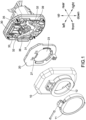
- FIG. 1 illustrates a charging socket for a charging connector to be plugged in, comprising an outer shell 10, a sliding cover 20, and a base 30 installed sequentially from front to back.
- the sliding cover 20 is provided on the front surface of the base 30, and the sliding cover 20 can be moved up and down relative to the base 30.
- the outer shell 10 covers the sliding cover 20 and the base 30, and the outer shell 10 is provided with a liftable dust cover 11 for opening or closing an opening 12 on the outer shell 10.
- the plug connecting part has a plurality of plug jacks 31, and the front surface of the base 30 has two baffles 32 located at the left front and right front of the plug connecting part to cover at least a part of the plug jacks 31, and at least a part of the plug jacks 31 are electrified plug jacks 31.
- Each baffle 32 has an outer wall surface and an inner wall surface, wherein the outer wall surface of each baffle 32 has an angled bend 321.
- the base 30 also has two recesses 34 spaced above the plug connecting part, two elastic elements 33 are provided in the two recesses 34, respectively, and the sliding cover 20 is connected to the two elastic elements 33 so that it can be moved up and down.
- the sliding cover 20 has an inserting hole 23 corresponding to the plug connecting part, an actuating part is provided on the rear surface of the sliding cover 20 and is located above the inserting hole 23, the rear surface of the sliding cover 20 has a projecting annular wall 20A along the contour of the sliding cover 20, the actuating part comprises two connecting rods 21a extending downward from the upper wall of the annular wall 20A, and two actuating rods 21b are respectively connected to the two connecting rods 21a and extended toward the left and right side walls of the annular wall 20A, and two positioning posts 21c are respectively provided at the connection of the two connecting rods 21a and the two actuating rods 21b and extended toward the direction of the base 30 (i.e., extended backward), and the two positioning posts 21c are connected to the two elastic
- the front surface of the base 30 has a projecting annular wall 38 along the contour of the base 30, and the two stop walls 39 are located on the left and right sides of the annular wall 38 and are projecting in the direction of the sliding cover 20 (i.e., the front), and the contour of the sliding cover 20 includes an upper contour and a lower contour, and the junction of the two contours forms an angle 28.
- the stop wall 39 forms a stopping effect to retain the angle 28.
- the left and right side walls of the annular wall 20A of the sliding cover 20 are each provided with a protrusion 25 (see FIG. 2 ), and the two protrusions 25 extend in the direction of the inserting hole 23 and both have a beveled surface 251, and the contour of the beveled surface 251 matches the contour of the angled bend 321 of the two baffles 32.
- the base 30 has two limit blocks 36 above the plug connecting part, and the sliding cover 20 has two limit slots 27 corresponding to the two limit blocks 36.
- the base 30 also has a pressing block 35 disposed between the two elastic elements 33 so that when the charging connector is plugged in, the charging connector presses against the pressing block 35 to move it rearwardly so that the sliding cover 20 can be moved downwardly relative to the base 30 to form the states as shown in FIGS. 3 and 4 .
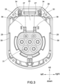
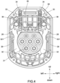
- FIG. 3 and FIG. 4 are schematic diagrams of the states of the charging connector plugged into the charging socket, in these states, the pressing block 35 is moved backward by the pressure of the charging connector, causing the sliding cover 20 to move downward, and at the same time, the actuating rod 21b of the sliding cover 20 pushes the two baffles 32 to swing to the left and right sides, and the angled bend 321 of the outer wall of the two baffles 32 follows the protrusion 25 of the sliding cover 20 to swing to the left and right sides, and the bottom wall of the two limit slots 27 of the sliding cover 20 then contacts the two limit blocks 36, and the angle 28 of the sliding cover 20 is stopped at the stop wall 39, causing the sliding cover 20 to stop moving.
Landscapes
- Engineering & Computer Science (AREA)
- Power Engineering (AREA)
- Transportation (AREA)
- Mechanical Engineering (AREA)
- Connector Housings Or Holding Contact Members (AREA)
Abstract
A charging socket, comprising sequentially an outer shell, a sliding cover, and a base, the sliding cover being provided on the front surface of the base and sliding up and down relative to the base, wherein the front surface of the base has two elastic elements spaced above the plug connecting part and two baffles covering at least a part of the plug connecting part. The sliding cover has an inserting hole corresponding to the plug connecting part, an actuating part is provided on the rear surface of the sliding cover located above the inserting hole and connected to the two elastic elements to push the two baffles to swing in opposite directions simultaneously.
Description
- The present disclosure relates to a charging socket for a vehicle, in particular a charging socket with a safety mechanism.
- As electric vehicles become more popular, many public places are increasingly equipped with electric vehicle charging stations.
- Although most of the common charging devices are equipped with a dust cover to cover the charging socket, it is inevitable that the installation in public areas is prone to damage by people, resulting in the plug jack of the charging socket being directly exposed, so that external contaminants (such as moisture, dust) will enter the plug jack, these contaminants will affect the normal use of the charging socket. In addition, if there is a lack of dust cover protection, it is also difficult to prevent small children from reaching into the jack, which may cause the risk of electric shock.
- In view of the aforementioned deficiencies, the present disclosure aims at providing a charging socket for vehicles, in particular a charging socket with a safety mechanism.
- In accordance with the purpose of the present disclosure, the charging socket is provided with an outer shell, a sliding cover, and a base, the sliding cover being provided on the front surface of the base and sliding up and down relative to the base, the base having a plug connecting part, the front surface of the base having two elastic elements spaced above the plug connecting part and two baffles covering at least a part of the plug connecting part. The sliding cover has an inserting hole corresponding to the plug connecting part, an actuating part is provided on the rear surface of the sliding cover located above the inserting hole and connected to the two elastic elements to push the two baffles to swing in opposite directions.
- Wherein, the rear surface of the sliding cover has an annular wall projecting along the contour of the sliding cover, the actuating part comprises two connecting rods extending downward from the upper wall of the annular wall, two actuating rods connected to the two connecting rods, and extending in the left and right directions, respectively, and two positioning posts located at the connection of the two connecting rods and the two actuating rods, respectively, extending in the direction of the base and connected to two elastic elements, respectively.
- Wherein, both the left and right side walls of the annular wall of the sliding cover have a protrusion extending in the direction of the inserting hole, and each of the protrusions has a beveled surface.
- Wherein, the two baffles are symmetrical and pivoted above the plug connecting part, each baffle including an outer wall surface and an inner wall surface, and the outer wall surface of the two baffles has an angled bend, and the contour of the angled bend of each baffle matches the contour of the beveled surface of each protrusion.
- Wherein, the base also has a pressing block disposed between the two elastic elements.
- Wherein, the front surface of the base has an annular wall projecting along the contour of the base, two stop walls are provided on the left and right sides of the annular wall, respectively, and the two stop walls project toward the direction of the sliding cover.
- Wherein, the two elastic elements are installed in two recesses.
- Wherein, the charging socket is also equipped with a dust cover that is mounted on the outer shell in a liftable manner.
- Wherein, the front surface of the base also has two limit blocks installed above the plug connecting part, and the sliding cover has two limit slots corresponding to the two limit blocks.
- Wherein, the contour of the sliding cover includes an upper contour and a lower contour, and the junction of the two contours forms an angle.
-
-
FIG. 1 is a schematic diagram of the charging socket of the present disclosure; -
FIG. 2 is a schematic diagram of the rear surface of the sliding cover of the charging socket of the present disclosure; -
FIG. 3 is a schematic diagram of the charging socket after the charging connector is plugged into the charging socket; -
FIG. 4 is a partial cross-sectional view ofFIG. 3 ; -
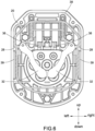
FIG. 5 is a schematic diagram of the charging socket without the charging connector plugged in; and -
Fig. 6 is a partial cross-sectional view ofFIG. 5 . - In order to clearly illustrate the specific implementation of the present disclosure, the structure, and the effect achieved, the following embodiments are provided and illustrated by drawings:
- The present disclosure is based on the direction of movement of the
sliding cover 20 as the up and down direction, the left and right sides of thesliding cover 20 as the left and right direction, and the front and rear sides of thesliding cover 20 as the front and rear direction. Wherein, the up and down directions, the left and right directions, and the front and rear directions are described as directions for illustration purposes.FIG. 1 illustrates a charging socket for a charging connector to be plugged in, comprising anouter shell 10, a slidingcover 20, and abase 30 installed sequentially from front to back. The slidingcover 20 is provided on the front surface of thebase 30, and thesliding cover 20 can be moved up and down relative to thebase 30. Theouter shell 10 covers thesliding cover 20 and thebase 30, and theouter shell 10 is provided with aliftable dust cover 11 for opening or closing anopening 12 on theouter shell 10. - Referring to
FIGS. 2 to 6 , the plug connecting part has a plurality ofplug jacks 31, and the front surface of thebase 30 has twobaffles 32 located at the left front and right front of the plug connecting part to cover at least a part of theplug jacks 31, and at least a part of theplug jacks 31 are electrifiedplug jacks 31. Eachbaffle 32 has an outer wall surface and an inner wall surface, wherein the outer wall surface of eachbaffle 32 has anangled bend 321. - The
base 30 also has tworecesses 34 spaced above the plug connecting part, twoelastic elements 33 are provided in the tworecesses 34, respectively, and thesliding cover 20 is connected to the twoelastic elements 33 so that it can be moved up and down. Further, thesliding cover 20 has aninserting hole 23 corresponding to the plug connecting part, an actuating part is provided on the rear surface of the slidingcover 20 and is located above theinserting hole 23, the rear surface of the slidingcover 20 has a projectingannular wall 20A along the contour of thesliding cover 20, the actuating part comprises two connectingrods 21a extending downward from the upper wall of theannular wall 20A, and two actuatingrods 21b are respectively connected to the two connectingrods 21a and extended toward the left and right side walls of theannular wall 20A, and twopositioning posts 21c are respectively provided at the connection of the two connectingrods 21a and the two actuatingrods 21b and extended toward the direction of the base 30 (i.e., extended backward), and the twopositioning posts 21c are connected to the twoelastic elements 33, respectively. When the slidingcover 20 is moved downward, the two actuatingrods 21b push the twobaffles 32 to swing synchronously in opposite directions. In the embodiment of the present disclosure, the contour of the two actuatingrods 21b is in the shape of a ladder. - The front surface of the
base 30 has a projectingannular wall 38 along the contour of thebase 30, and the twostop walls 39 are located on the left and right sides of theannular wall 38 and are projecting in the direction of the sliding cover 20 (i.e., the front), and the contour of thesliding cover 20 includes an upper contour and a lower contour, and the junction of the two contours forms anangle 28. When the slidingcover 20 is moved downward, thestop wall 39 forms a stopping effect to retain theangle 28. - The left and right side walls of the
annular wall 20A of thesliding cover 20 are each provided with a protrusion 25 (seeFIG. 2 ), and the twoprotrusions 25 extend in the direction of theinserting hole 23 and both have abeveled surface 251, and the contour of thebeveled surface 251 matches the contour of theangled bend 321 of the twobaffles 32. When the twobaffles 32 are swung to the left and right sides, theangled bend 321 of the outer wall surface of the twobaffles 32 follows the contour of theprotrusion 25 swinging to the left and right sides. In addition, thebase 30 has twolimit blocks 36 above the plug connecting part, and thesliding cover 20 has twolimit slots 27 corresponding to the twolimit blocks 36. When the slidingcover 20 moves downward, the bottom wall of the twolimit slots 27 of the slidingcover 20 contacts the twolimit blocks 36 so that thesliding cover 20 stops moving downward. - The
base 30 also has apressing block 35 disposed between the twoelastic elements 33 so that when the charging connector is plugged in, the charging connector presses against thepressing block 35 to move it rearwardly so that thesliding cover 20 can be moved downwardly relative to thebase 30 to form the states as shown inFIGS. 3 and4 . - Referring to
FIG. 3 andFIG. 4 , which are schematic diagrams of the states of the charging connector plugged into the charging socket, in these states, thepressing block 35 is moved backward by the pressure of the charging connector, causing the slidingcover 20 to move downward, and at the same time, the actuatingrod 21b of the slidingcover 20 pushes the twobaffles 32 to swing to the left and right sides, and theangled bend 321 of the outer wall of the twobaffles 32 follows theprotrusion 25 of the slidingcover 20 to swing to the left and right sides, and the bottom wall of the twolimit slots 27 of the slidingcover 20 then contacts the twolimit blocks 36, and theangle 28 of the slidingcover 20 is stopped at thestop wall 39, causing the slidingcover 20 to stop moving. - When the charging connector is pulled out, the sliding
cover 20 moves upward due to the elasticity of theelastic element 33, and thepressing block 35 moves forward and returns to its position due to the absence of pressure from the charging connector, while the twobaffles 32 are returned to the positions as shown inFIGS. 5 and6 .
Claims (10)
- A charging socket, comprising an outer shell(10), a sliding cover(20), and a base(30) installed sequentially from front to back, the sliding cover(20) being provided on the front surface of the base(30) and moving up and down relative to the base,(30) the base having a plug connecting part, characterized in that:the front surface of the base(30) having two elastic elements(33) spaced above the plug connecting part and two baffles(32) covering at least a part of the plug connecting part; andthe sliding cover(20) having an inserting hole(23) corresponding to the plug connecting part, an actuating part being provided on the rear surface of the sliding cover(20) located above the inserting hole(23) and connected to the two elastic elements(33) to push the two baffles(32) to swing in opposite directions.
- The charging socket according to claim 1, wherein the rear surface of the sliding cover(20) has an annular wall(20A) projecting along the contour of the sliding cover(20), the actuating part comprises two connecting rods(21a) extending downward from the upper wall of the annular wall(20A), two actuating rods(21b) connected to the two connecting rods(21a), and extending in the left and right directions, respectively, and two positioning posts(21c) located at the connection of the two connecting rods(21a) and the two actuating rods(21b), respectively, extending in the direction of the base(30) and connected to two elastic elements(33), respectively.
- The charging socket according to claim 2, wherein both the left and right side walls of the annular wall(20A) of the sliding cover(20) have a protrusion(25) extending in the direction of the inserting hole(23), and each of the protrusions(25) has a beveled surface(251).
- The charging socket according to claim 3, wherein the two baffles(32) are symmetrical and pivoted above the plug connecting part, each baffle including an outer wall surface and an inner wall surface, and the outer wall surface of the two baffles(32) has an angled bend(321), and the contour of the angled bend(321) of each baffle(32) matches the contour of the beveled surface(251) of each protrusion(25).
- The charging socket according to any one of claims 1 to 4, wherein the base also has a pressing block(35) disposed between the two elastic elements(33).
- The charging socket according to any one of claims 1 to 5, wherein the front surface of the base(30) has an annular wall(38) projecting along the contour of the base(30), two stop walls(39) are provided on the left and right sides of the annular wall(38), respectively, and the two stop walls(39) project toward the direction of the sliding cover(20).
- The charging socket according to any one of claims 1 to 6, wherein the two elastic elements(33) are installed in two recesses(34).
- The charging socket according to claim 4, wherein the charging socket is also equipped with a dust cover(11) that is mounted on the outer shell(10) in a liftable manner.
- The charging socket according to any one of claims 1 to 8, wherein the front surface of the base(30) also has two limit blocks(36) installed above the plug connecting part, and the sliding cover(20) has two limit slots(27) corresponding to the two limit blocks(36).
- The charging socket according to any one of claims 1 to 9, wherein the contour of the sliding cover(20) includes an upper contour and a lower contour, and the junction of the two contours forms an angle(28).
Applications Claiming Priority (1)
| Application Number | Priority Date | Filing Date | Title |
|---|---|---|---|
| TW112116400A TWI855667B (en) | 2023-05-03 | 2023-05-03 | Charging socket |
Publications (1)
| Publication Number | Publication Date |
|---|---|
| EP4459807A1 true EP4459807A1 (en) | 2024-11-06 |
Family
ID=87747936
Family Applications (1)
| Application Number | Title | Priority Date | Filing Date |
|---|---|---|---|
| EP23191609.9A Pending EP4459807A1 (en) | 2023-05-03 | 2023-08-16 | Charging socket |
Country Status (2)
| Country | Link |
|---|---|
| EP (1) | EP4459807A1 (en) |
| TW (1) | TWI855667B (en) |
Citations (5)
| Publication number | Priority date | Publication date | Assignee | Title |
|---|---|---|---|---|
| DE102010048713A1 (en) * | 2010-10-19 | 2012-04-19 | Amad - Mennekes Holding Gmbh & Co. Kg | Device for securing charging plug socket for electric car, has protective flap that is formed such that pivoting of flap is performed by pressing of plug |
| EP2685568A1 (en) * | 2012-06-14 | 2014-01-15 | Scame Parre S.p.A. | Industrial socket with live contacts protection device |
| CN110380266A (en) * | 2019-08-15 | 2019-10-25 | 康思立达(上海)汽车科技有限公司 | Electric automobile charging pile socket protecting device |
| US20220140518A1 (en) * | 2020-08-10 | 2022-05-05 | Pass & Seymour, Inc. | Tamper-resistant electrical wiring devices |
| WO2022200152A1 (en) * | 2021-03-24 | 2022-09-29 | Phoenix Contact E-Mobility Gmbh | Closure device |
Family Cites Families (6)
| Publication number | Priority date | Publication date | Assignee | Title |
|---|---|---|---|---|
| DE102014114214A1 (en) * | 2014-09-30 | 2016-03-31 | Phoenix Contact E-Mobility Gmbh | Electrical outlet |
| CN106450900A (en) * | 2016-08-22 | 2017-02-22 | 中山市创享电器有限公司 | A socket with a reset sealing device |
| IT201700090346A1 (en) * | 2017-08-04 | 2019-02-04 | Gewiss Spa | CONNECTOR FOR RECHARGING ELECTRIC VEHICLES |
| CN209056671U (en) * | 2018-12-30 | 2019-07-02 | 南京康尼新能源汽车零部件有限公司 | Push type charging socket protective cover |
| CN113734028B (en) * | 2021-09-26 | 2022-06-03 | 江苏数字鹰科技股份有限公司 | A kind of electric vehicle vehicle-mounted rescue equipment and rescue method |
| CN114784550A (en) * | 2022-04-22 | 2022-07-22 | 马嘶顿特新能源科技(上海)有限公司 | Charging socket and charging pile |
-
2023
- 2023-05-03 TW TW112116400A patent/TWI855667B/en active
- 2023-08-16 EP EP23191609.9A patent/EP4459807A1/en active Pending
Patent Citations (5)
| Publication number | Priority date | Publication date | Assignee | Title |
|---|---|---|---|---|
| DE102010048713A1 (en) * | 2010-10-19 | 2012-04-19 | Amad - Mennekes Holding Gmbh & Co. Kg | Device for securing charging plug socket for electric car, has protective flap that is formed such that pivoting of flap is performed by pressing of plug |
| EP2685568A1 (en) * | 2012-06-14 | 2014-01-15 | Scame Parre S.p.A. | Industrial socket with live contacts protection device |
| CN110380266A (en) * | 2019-08-15 | 2019-10-25 | 康思立达(上海)汽车科技有限公司 | Electric automobile charging pile socket protecting device |
| US20220140518A1 (en) * | 2020-08-10 | 2022-05-05 | Pass & Seymour, Inc. | Tamper-resistant electrical wiring devices |
| WO2022200152A1 (en) * | 2021-03-24 | 2022-09-29 | Phoenix Contact E-Mobility Gmbh | Closure device |
Also Published As
| Publication number | Publication date |
|---|---|
| TW202444590A (en) | 2024-11-16 |
| TWI855667B (en) | 2024-09-11 |
Similar Documents
| Publication | Publication Date | Title |
|---|---|---|
| CN102570144B (en) | Electrical pop out device | |
| CN102593647A (en) | Safe socket with protective door | |
| CN102447186A (en) | Leakage protection socket | |
| CN103840317B (en) | Double-lever interlocking connector | |
| KR101256629B1 (en) | Wall surface undergrounding type outlet box of apartment | |
| CN2161000Y (en) | Auto-closed dust-and electric shock-prevention safety socket | |
| CN205609812U (en) | Extension line socket with five -hole socket protective door structure and have this structure | |
| CN108336681B (en) | Electrical switchgear cabinet | |
| KR200486264Y1 (en) | Assembling fixed terminal connecting device | |
| CN102097699B (en) | Power socket with baffle locking mechanism | |
| CN109861022B (en) | Protection door structure of five-hole socket and five-hole socket | |
| JPS6330140Y2 (en) | ||
| CN218914798U (en) | Ceiling lamp | |
| CN109546416B (en) | Socket for electrical engineering construction | |
| CN214428805U (en) | Socket protection door | |
| TWI855667B (en) | Charging socket | |
| CN212182622U (en) | Universal protective door and socket | |
| CN214100026U (en) | Agricultural safe outdoor power strip | |
| CN110165508B (en) | Self-power-off safety socket | |
| CN201699218U (en) | Socket with protective gate | |
| CN2461176Y (en) | Electric shock safety device for socket | |
| CN219086351U (en) | Power socket panel | |
| CN217427162U (en) | IP55 waterproof plug | |
| CN214589368U (en) | Socket protection against electric shock shutter | |
| CN222052148U (en) | Protect door assembly and socket |
Legal Events
| Date | Code | Title | Description |
|---|---|---|---|
| PUAI | Public reference made under article 153(3) epc to a published international application that has entered the european phase |
Free format text: ORIGINAL CODE: 0009012 |
|
| STAA | Information on the status of an ep patent application or granted ep patent |
Free format text: STATUS: THE APPLICATION HAS BEEN PUBLISHED |
|
| AK | Designated contracting states |
Kind code of ref document: A1 Designated state(s): AL AT BE BG CH CY CZ DE DK EE ES FI FR GB GR HR HU IE IS IT LI LT LU LV MC ME MK MT NL NO PL PT RO RS SE SI SK SM TR |
|
| STAA | Information on the status of an ep patent application or granted ep patent |
Free format text: STATUS: REQUEST FOR EXAMINATION WAS MADE |
|
| 17P | Request for examination filed |
Effective date: 20241219 |