EP4459793A1 - Antenna system and terminal device - Google Patents
Antenna system and terminal device Download PDFInfo
- Publication number
- EP4459793A1 EP4459793A1 EP23851248.7A EP23851248A EP4459793A1 EP 4459793 A1 EP4459793 A1 EP 4459793A1 EP 23851248 A EP23851248 A EP 23851248A EP 4459793 A1 EP4459793 A1 EP 4459793A1
- Authority
- EP
- European Patent Office
- Prior art keywords
- radiation branch
- antenna system
- point
- radiation
- feed
- Prior art date
- Legal status (The legal status is an assumption and is not a legal conclusion. Google has not performed a legal analysis and makes no representation as to the accuracy of the status listed.)
- Granted
Links
Images




Classifications
-
- H—ELECTRICITY
- H01—ELECTRIC ELEMENTS
- H01Q—ANTENNAS, i.e. RADIO AERIALS
- H01Q1/00—Details of, or arrangements associated with, antennas
- H01Q1/12—Supports; Mounting means
- H01Q1/22—Supports; Mounting means by structural association with other equipment or articles
- H01Q1/24—Supports; Mounting means by structural association with other equipment or articles with receiving set
- H01Q1/241—Supports; Mounting means by structural association with other equipment or articles with receiving set used in mobile communications, e.g. GSM
- H01Q1/242—Supports; Mounting means by structural association with other equipment or articles with receiving set used in mobile communications, e.g. GSM specially adapted for hand-held use
- H01Q1/243—Supports; Mounting means by structural association with other equipment or articles with receiving set used in mobile communications, e.g. GSM specially adapted for hand-held use with built-in antennas
-
- H—ELECTRICITY
- H01—ELECTRIC ELEMENTS
- H01Q—ANTENNAS, i.e. RADIO AERIALS
- H01Q1/00—Details of, or arrangements associated with, antennas
- H01Q1/50—Structural association of antennas with earthing switches, lead-in devices or lightning protectors
-
- H—ELECTRICITY
- H01—ELECTRIC ELEMENTS
- H01Q—ANTENNAS, i.e. RADIO AERIALS
- H01Q1/00—Details of, or arrangements associated with, antennas
- H01Q1/52—Means for reducing coupling between antennas; Means for reducing coupling between an antenna and another structure
- H01Q1/521—Means for reducing coupling between antennas; Means for reducing coupling between an antenna and another structure reducing the coupling between adjacent antennas
-
- H—ELECTRICITY
- H01—ELECTRIC ELEMENTS
- H01Q—ANTENNAS, i.e. RADIO AERIALS
- H01Q21/00—Antenna arrays or systems
- H01Q21/28—Combinations of substantially independent non-interacting antenna units or systems
-
- H—ELECTRICITY
- H01—ELECTRIC ELEMENTS
- H01Q—ANTENNAS, i.e. RADIO AERIALS
- H01Q5/00—Arrangements for simultaneous operation of antennas on two or more different wavebands, e.g. dual-band or multi-band arrangements
- H01Q5/30—Arrangements for providing operation on different wavebands
- H01Q5/307—Individual or coupled radiating elements, each element being fed in an unspecified way
- H01Q5/314—Individual or coupled radiating elements, each element being fed in an unspecified way using frequency dependent circuits or components, e.g. trap circuits or capacitors
- H01Q5/328—Individual or coupled radiating elements, each element being fed in an unspecified way using frequency dependent circuits or components, e.g. trap circuits or capacitors between a radiating element and ground
-
- H—ELECTRICITY
- H01—ELECTRIC ELEMENTS
- H01Q—ANTENNAS, i.e. RADIO AERIALS
- H01Q5/00—Arrangements for simultaneous operation of antennas on two or more different wavebands, e.g. dual-band or multi-band arrangements
- H01Q5/30—Arrangements for providing operation on different wavebands
- H01Q5/307—Individual or coupled radiating elements, each element being fed in an unspecified way
- H01Q5/314—Individual or coupled radiating elements, each element being fed in an unspecified way using frequency dependent circuits or components, e.g. trap circuits or capacitors
- H01Q5/335—Individual or coupled radiating elements, each element being fed in an unspecified way using frequency dependent circuits or components, e.g. trap circuits or capacitors at the feed, e.g. for impedance matching
-
- H—ELECTRICITY
- H01—ELECTRIC ELEMENTS
- H01Q—ANTENNAS, i.e. RADIO AERIALS
- H01Q5/00—Arrangements for simultaneous operation of antennas on two or more different wavebands, e.g. dual-band or multi-band arrangements
- H01Q5/30—Arrangements for providing operation on different wavebands
- H01Q5/307—Individual or coupled radiating elements, each element being fed in an unspecified way
- H01Q5/342—Individual or coupled radiating elements, each element being fed in an unspecified way for different propagation modes
- H01Q5/35—Individual or coupled radiating elements, each element being fed in an unspecified way for different propagation modes using two or more simultaneously fed points
-
- H—ELECTRICITY
- H01—ELECTRIC ELEMENTS
- H01Q—ANTENNAS, i.e. RADIO AERIALS
- H01Q5/00—Arrangements for simultaneous operation of antennas on two or more different wavebands, e.g. dual-band or multi-band arrangements
- H01Q5/30—Arrangements for providing operation on different wavebands
- H01Q5/307—Individual or coupled radiating elements, each element being fed in an unspecified way
- H01Q5/342—Individual or coupled radiating elements, each element being fed in an unspecified way for different propagation modes
- H01Q5/357—Individual or coupled radiating elements, each element being fed in an unspecified way for different propagation modes using a single feed point
- H01Q5/364—Creating multiple current paths
- H01Q5/371—Branching current paths
-
- H—ELECTRICITY
- H01—ELECTRIC ELEMENTS
- H01Q—ANTENNAS, i.e. RADIO AERIALS
- H01Q5/00—Arrangements for simultaneous operation of antennas on two or more different wavebands, e.g. dual-band or multi-band arrangements
- H01Q5/30—Arrangements for providing operation on different wavebands
- H01Q5/378—Combination of fed elements with parasitic elements
-
- H—ELECTRICITY
- H01—ELECTRIC ELEMENTS
- H01Q—ANTENNAS, i.e. RADIO AERIALS
- H01Q5/00—Arrangements for simultaneous operation of antennas on two or more different wavebands, e.g. dual-band or multi-band arrangements
- H01Q5/40—Imbricated or interleaved structures; Combined or electromagnetically coupled arrangements, e.g. comprising two or more non-connected fed radiating elements
- H01Q5/45—Imbricated or interleaved structures; Combined or electromagnetically coupled arrangements, e.g. comprising two or more non-connected fed radiating elements using two or more feeds in association with a common reflecting, diffracting or refracting device
-
- H—ELECTRICITY
- H01—ELECTRIC ELEMENTS
- H01Q—ANTENNAS, i.e. RADIO AERIALS
- H01Q9/00—Electrically-short antennas having dimensions not more than twice the operating wavelength and consisting of conductive active radiating elements
- H01Q9/04—Resonant antennas
- H01Q9/30—Resonant antennas with feed to end of elongated active element, e.g. unipole
- H01Q9/42—Resonant antennas with feed to end of elongated active element, e.g. unipole with folded element, the folded parts being spaced apart a small fraction of the operating wavelength
Definitions
- This application relates to the field of antenna technologies, and in particular, to an antenna system and a terminal device.
- terminal devices With rapid development of terminal devices and increasing use requirements of people, terminal devices are increasingly widely used in people's production and life, and communication quality requirements of users on terminal devices are also increasingly high.
- the communication quality of the terminal device depends heavily on performance of a terminal antenna disposed on the terminal device.
- use demand of a multiple-input multiple-output (multi-input multi-output, MIMO) antenna technology on a terminal device becomes increasingly high.
- a current terminal device has gradually developed from an antenna system of 2*2 to an antenna system of 4*4. Except for an antenna for wireless fidelity (wireless fidelity, WIFI) and a global positioning system (global positioning system, GPS) at the beginning, 8 to 15 antennas with different functions are usually accommodated on the terminal device.
- wireless fidelity wireless fidelity
- GPS global positioning system
- a full-screen structure solution with an ultra-narrow frame is used, which requires high structure compactness of the terminal device.
- the terminal device After the terminal device satisfies the MIMO communication specification, more antennas need to be added, and space of the antenna is further compressed.
- a MIMO antenna In the terminal device with a highly-compressed space, a MIMO antenna usually needs to use different antennas to transmit and receive signals of a same frequency band, and consequently, when the signals in the same frequency band are transmitted and received by the different antennas, isolation between the antennas is reduced, and performance of an antenna system is reduced.
- This application provides an antenna system and a terminal device, to improve isolation between antennas, to improve performance of an antenna system and improve communication quality.
- an antenna system includes: a first radiation branch, a second radiation branch and a third radiation branch, where the first radiation branch and the second radiation branch are electrically connected, and a first gap is provided between the second radiation branch and the third radiation branch; a first feed point is disposed on the first radiation branch, and the first feed point is located at an end of the first radiation branch away from the second radiation branch; a second feed point is disposed on the second radiation branch, and the second feed point is located at an end of the second radiation branch away from the first radiation branch; the antenna system further includes: a first ground return point, where the first ground return point is located at an electrical connection between the first radiation branch and the second radiation branch, and the first ground return point is located between the first feed point and the second feed point; and a second ground return point is disposed on the third radiation branch, and the second ground return point is located at an end of the third radiation branch away from the first gap.
- the third radiation branch that can be decoupled is added, and no feed point is provided on the third radiation branch, but the ground return point is arranged, so that the third radiation branch is used as a suspended parasitic radiation branch to influence an excitation mode of the whole antenna system.
- the third radiation branch is added, so that differential-mode currents are formed on the first radiation branch and the second radiation branch when a feed source 1 and a feed source 2 feed signals of a same frequency.
- the first feed point is configured to feed a high-frequency signal
- the second feed point is configured to feed a high-frequency signal and/or a medium-frequency signal.
- the third radiation branch is added, so that differential-mode currents can be formed on the first radiation branch and the second radiation branch, some currents on the two radiation branches cancel each other, so that a signal flowing from the feed source 2 to the first radiation branch is reduced, a signal flowing from the feed source 1 to the second radiation branch is also reduced, mutual coupling between the two radiation branches in the MIMO scenario is reduced, isolation between the two radiation branches in the MIMO scenario at a high frequency is improved, antenna performance of the whole antenna system in a high-frequency band in the MIMO scenario is improved, and communication quality of the high-frequency band in the MIMO scenario is improved.
- the second feed point may alternatively feed a medium-frequency signal, so that the second radiation branch may be compatible with a medium-frequency band, and the antenna system supports the high-frequency band while also being compatible with the medium-frequency band, to expand a bandwidth of the antenna system.
- a current mode in the antenna system is a differential mode.
- the high-frequency signal is a signal in an N41 frequency band.
- the signal flowing from the feed source 2 to the first radiation branch is reduced, the signal flowing from the feed source 1 to the second radiation branch is also reduced, mutual coupling between the two radiation branches in the MIMO scenario is reduced, the isolation between the two radiation branches in the MIMO scenario at the N41 frequency band is improved, the antenna performance of the whole antenna system at the N41 frequency band in the MIMO scenario is improved, and communication quality at the N41 frequency band in the MIMO scenario is improved.
- a length difference between a length of the third radiation branch and a quarter wavelength of the signal in the N41 frequency band is less than a length error threshold.
- the length of the third radiation branch may be a length of a quarter wavelength of a signal fed by the feed source 2, for example, may be a length equal to the quarter wavelength, or may be a length close to the quarter wavelength, a difference between the length of the third radiation branch and the quarter wavelength is less than a preset length error threshold, and the length error threshold may be 0.5 mm, 1 mm, or the like, to ensure that a resonance state is achieved when the signal is fed, and maintain antenna performance.
- the length of the third radiation branch may be a length of a quarter of a wavelength corresponding to a center frequency of the N41 frequency band or a length close to the quarter wavelength, to ensure a resonance state.
- a distance between the first ground return point and the second feed point is greater than a distance between the first feed point and the first ground return point.
- a length that is of the second radiation branch and that is provided when the second radiation branch is used as a main radiation branch when the feed source 2 feeds a signal is greater than a length that is of the first radiation branch and that is provided when the first radiation branch is used as a main radiation branch when the feed source 1 feeds a signal. Therefore, in a resonant mode, a frequency band that matches the second radiation branch between the first ground return point and the second feed point is lower than a frequency band that matches the first radiation branch between the first feed point and the first ground return point, and the second radiation branch can be compatible with the medium-frequency band, so that the antenna system is compatible with the medium-frequency band while supporting the high-frequency band, to expand the bandwidth of the antenna system.
- the second ground return point is located at an end of the third radiation branch away from the first gap, and a length of the third radiation branch is greater than a distance between an end of the second radiation branch close to the first gap to the second feed point.
- the second ground return point is located at the end of the third radiation branch away from the first gap, if the length of the third radiation branch is too short, a resonant frequency corresponding to a case in which a current mode excited by the antenna system is the differential mode is too high.
- the length of the third radiation branch is greater than the distance between the end of the second radiation branch close to the first gap to the second feed point, that a resonance frequency of the third radiation branch and a frequency band at which decoupling is required can be matched can be ensured, to ensure decoupling effect.
- a first tuning circuit is further disposed on the third radiation branch, and an end of the third radiation branch close to the first gap is grounded through the first tuning circuit.
- the first tuning circuit is disposed, so that a ground return tuning point can be added on the third radiation branch, so that a tuning capability of the antenna system is improved, and therefore the performance of the antenna system can be further improved.
- a second tuning circuit is further disposed on the second radiation branch, the second tuning circuit is located between the second feed point and the first ground return point, and the second radiation branch is grounded through the second tuning circuit.
- the second tuning circuit is disposed, so that a tuning point can be added on the second radiation branch, the tuning capability of the antenna system is improved, and therefore the performance of the antenna system can be further improved.
- the antenna system further includes a third tuning circuit, and the first feed point is grounded through the third tuning circuit.
- the antenna system further includes a fourth tuning circuit, and the second feed point is grounded through the fourth tuning circuit.
- the third tuning circuit and/or the fourth tuning circuit are/is disposed, so that the tuning capability of the antenna system is improved, and therefore the performance of the antenna system can be further improved.
- a shape of the first radiation branch is L-shaped.
- the first radiation branch of the L-shaped structure is used, so that an antenna size can be reduced and an antenna layout is facilitated while the antenna size is maintained.
- a terminal device includes the antenna systems according to any one of the technical solutions of the first aspect.
- first”, “second”, and “third” are merely intended for a purpose of description, and shall not be understood as an indication or implication of relative importance or implicit indication of the number of indicated technical features. Therefore, a feature limited by “first”, “second”, and “third” may explicitly or implicitly include one or more features.
- An antenna system in embodiments of this application may be applied to a terminal device, for example, a mobile phone, a tablet computer, a wearable device, a vehicle-mounted device, an augmented reality (augmented reality, AR)/virtual reality (virtual reality, VR) device, a notebook computer, an ultra-mobile personal computer (ultra-mobile personal computer, UMPC), a netbook, or a personal digital assistant (personal digital assistant, PDA).
- a terminal device for example, a mobile phone, a tablet computer, a wearable device, a vehicle-mounted device, an augmented reality (augmented reality, AR)/virtual reality (virtual reality, VR) device, a notebook computer, an ultra-mobile personal computer (ultra-mobile personal computer, UMPC), a netbook, or a personal digital assistant (personal digital assistant, PDA).
- a specific type of the terminal device is not limited in embodiments of this application.
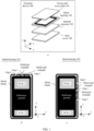
- FIG. 1 is a schematic structural diagram of a terminal device 100 according to an embodiment of this application.
- the terminal device 100 provided in this embodiment of this application may be provided with a screen and cover plate 101, a metal housing 102, an internal structure 103, and a rear cover 104 in sequence along a z-axis from top to bottom.
- the screen and cover plate 101 may be configured to implement a display function of the terminal device 100.
- the metal housing 102 may be used as a main framework of the terminal device 100 to provide rigid support for the terminal device 100.
- the internal structure 103 may include a collection of electronic components and mechanical components that implement various functions of the terminal device 100.
- the internal structure 103 may include a shielding cover, screws, strengthening ribs, and the like.
- the rear cover 104 may be an exterior surface of the back of the terminal device 100.
- the rear cover 104 may be made of a glass material, a ceramic material, plastic, and the like in different implementations.
- An antenna system provided in an embodiment of this application can be applied in the terminal device 100 shown in figure a in FIG. 1 to support wireless communication function of the terminal device 100.
- the antenna system may be arranged on the metal housing 102 of the terminal device 100.
- the antenna system involved in the antenna solution may be arranged on the rear cover 104 of the terminal device 100, or the like.
- FIG. 1 shows a schematic composition of the metal housing 102.
- a figure b in FIG. 1 shows an example in which the antenna system is arranged on a short side of the terminal device
- a figure c in FIG. 1 shows an example in which the antenna system is arranged on a long side of the terminal device.
- the antenna system may alternatively be disposed on a short side of the terminal device and a long side adjacent to the short side.
- the figure b in FIG. 1 is used as an example for description, and the metal housing 102 may be made of a metal material such as aluminum alloy. As shown in figure b in FIG.
- a reference ground may be arranged on the metal housing 102.
- the reference ground may be a metal material with a large area, which is used to provide most of the rigid support, while providing a zero potential reference for various electronic components.
- a metal frame may further be arranged on a periphery of the reference ground.
- the metal frame may be a complete and closed metal frame, and the metal frame may include a partially or completely suspended metal strip.
- the metal frame may alternatively be a metal frame interrupted by one or more gaps as shown in figure b in FIG. 1 .
- FIG. 1 For example, in the example of figure b in FIG.
- a gap 1, a gap 2, and a gap 3 may be provided at different positions of the metal frame. These gaps can break the metal frame to obtain individual metal branches. In some embodiments, some or all of these metal branches can be used as antenna radiation branches, to implement structural reuse during antenna disposing and reduce difficulty of antenna disposing. When the metal branch is used as an antenna radiation branch, a position of a gap corresponding to one end of the metal branch or positions of gaps corresponding to two ends of the metal branch can be flexibly selected based on antenna disposing.
- one or more metal pins may further be arranged on the metal frame.
- the metal pins may be provided with screw holes for securing other structural parts by screws.
- the metal pin may be coupled to a feed point to feed an antenna through the metal pin when the metal branch connected to the metal pin is used as a radiation branch of the antenna.
- the metal pins may alternatively be connected to other electronic components through coupling to achieve corresponding electrical connection functions.
- the metal pin in figure b and figure c in FIG. 1 , the metal pin may be coupled to the feed point or may be grounded.
- a printed circuit board printed circuit board, PCB
- a main board (main board) and a sub board (sub board) of a board split design are taken as an example.
- the main board and the sub board may alternatively be connected of, for example, an L-PCB design.
- the main board (for example, a PCB 1) may be configured to carry electronic components that implement various functions of the terminal device 100, such as a processor, a memory, a radio frequency module.
- the sub board (such as a PCB 2) may alternatively be used to carry electronic components, such as a universal serial bus (universal serial bus, USB) interface and a related circuit, and a speak box (speak box).
- the sub board may further be configured to carry a radio frequency circuit or the like corresponding to an antenna arranged at the bottom (that is, a part in a negative direction of a y-axis of the terminal device).
- various radiation branches mentioned below are the metal radiation branches mentioned above.
- terminal devices With rapid development of terminal devices and increasing use requirements of people, terminal devices are increasingly widely used in people's production and life, and communication quality requirements of users on terminal devices are also increasingly high.
- the communication quality of the terminal device depends heavily on performance of a terminal antenna disposed on the terminal device.
- use demand of a MIMO antenna technology on a terminal device becomes increasingly high.
- an antenna system of 2*2 to an antenna system of 4*4 have been gradually developed. Except for an antenna for WIFI and a GPS at the beginning, 8 to 15 antennas with different functions are usually accommodated on the terminal device.
- a full-screen structure solution with an ultra-narrow frame is used, which requires high structure compactness of the terminal device.
- the terminal device After the terminal device satisfies the MIMO communication specification, more antennas need to be added, and space of the antenna is further compressed.
- a MIMO antenna In the terminal device with a highly-compressed space, a MIMO antenna usually needs to use different antennas to transmit and receive signals of a same frequency band, and consequently, when the signals in the same frequency band are transmitted and received by the different antennas, isolation between the antennas is reduced, and performance of an antenna system is reduced.
- a common MIMO antenna includes an antenna 1 and an antenna 2.
- a feed point 1 is disposed on the antenna 1, and the feed point 1 may be connected to a feed source a; a feed point 2 is disposed on the antenna 2, and the feed point 2 may be connected to a feed source b; and the antenna 1 and the antenna 2 are grounded through a same ground return point.
- a signal in an N41 frequency band is radiated.
- the two feed points respectively feed signals in the N41 frequency band (2.6 GHz)
- a curve (S12) of isolation between the two antennas can be seen in figure b in FIG. 2 , which is only -8 decibels (dB). This cannot meet requirement of antenna performance.
- an excitation mode is changed by adding a parasitic branch used for decoupling in an original antenna system and disposing a gap between the original antennas.
- differential mode currents can be generated on the original two antennas, so that some currents distributed on the original two antennas are canceled, so that a signal flowing from the feed source a to the antenna 2 is reduced, a signal flowing from the feed source b to the antenna 1 is also reduced, mutual coupling between the two antennas is reduced, and the isolation between the two antennas is improved.
- FIG. 3 is a schematic diagram of a structure of an antenna system according to an embodiment of this application.
- a third radiation branch 303 for decoupling is added in the antenna system, and the added third radiation branch 303 can change a current mode in the antenna system and improve isolation between different antennas.
- the antenna system includes a first radiation branch 301, a second radiation branch 302, and a third radiation branch 303.
- the first radiation branch 301 and the second radiation branch 302 are electrically connected, and the first radiation branch 301 and the second radiation branch 302 are of an integral structure connected together structurally with different functions and effects as two radiators.
- the third radiation branch 303 and the second radiation branch 302 are sequentially arranged along a length direction, and a first gap 304 is provided between the second radiation branch 302 and the third radiation branch 303.
- a first feed point 305 is disposed on the first radiation branch 301, and the first feed point 305 is located at an end of the first radiation branch 301 away from the second radiation branch 302.
- a second feed point 306 is disposed on the second radiation branch 302, and the second feed point 306 is located at an end of the second radiation branch 302 away from the first radiation branch 301.
- the antenna system further includes: a first ground return point 307, the first ground return point 307 is located at an electrical connection between the first radiation branch 301 and the second radiation branch 302, and the first ground return point 307 is located between the first feed point 305 and the second feed point 306.
- the first radiation branch 301 and the second radiation branch 302 share the first ground return point 307.
- a second ground return point 308 is disposed on the third radiation branch 303, and the second ground return point 308 is located at an end of the third radiation branch 303 away from the first gap 304.
- the first feed point 305 may be connected to the feed source 1, and the second feed point 306 may be connected to the feed source 2.
- the feed point and the feed source may be directly connected, or may be connected through a series capacitor, or may be connected through a matching circuit in another matching form, which is not limited in this embodiment of this application.
- the third radiation branch 303 that can be decoupled is added, and no feed point is provided on the third radiation branch 303, but the ground return point is arranged, so that the third radiation branch 303 is used as a suspended parasitic radiation branch to influence an excitation mode of the whole antenna system.
- the third radiation branch 303 is added, so that differential-mode currents are formed on the first radiation branch 301 and the second radiation branch 302 when a feed source 1 and a feed source 2 feed signals of a same frequency.
- the feed source 2 may feed low-frequency signals through the second feed point 306, such as low-frequency signals in bands such as B5 and B8; or may feed medium-frequency signals, such as medium-frequency signals in frequency bands such as B1, B2, and B3, or may feed high-frequency signals in frequency bands such as B7 and B41.
- the feed source 1 may feed low-frequency signals through the first feed point 305, such as low-frequency signals in bands such as B5 and B8; or may feed medium-frequency signals, such as medium-frequency signals in frequency bands such as B1, B2, and B3, or may feed high-frequency signals in frequency bands such as B7 and B41.
- a frequency band of a fed signal is not limited in this embodiment of this application.
- the feed source 2 may feed high-frequency signals through the second feed point 306, such as signals in bands such as B7 and N41; or may feed medium-frequency signals, such as signals in frequency bands such as B1, B2, and B3.
- the feed source 1 may feed a high-frequency signal through the first feed point 305.
- the third radiation branch 303 is added, so that differential-mode currents can be formed on the first radiation branch 301 and the second radiation branch 302, some currents on the two radiation branches cancel each other, so that a signal flowing from the feed source 2 to the first radiation branch 301 is reduced, a signal flowing from the feed source 1 to the second radiation branch 302 is also reduced, mutual coupling between the two radiation branches in the MIMO scenario is reduced, isolation between the two radiation branches in the MIMO scenario at a high frequency is improved, antenna performance of the whole antenna system in a high-frequency band in the MIMO scenario is improved, and communication quality of the high-frequency band in the MIMO scenario is improved.
- a port of the antenna system connected to the feed source 2 is a 1 port
- a port of the antenna system connected to the feed source 1 is a 2 port.
- S12 and S21 are forward transmission coefficients.
- S21 is used as an example, S21 represents a magnitude of energy transmitted from the 2 port to the 1 port.
- S21 is used to indicate isolation
- a smaller value indicates larger isolation.
- S11 and S22 are the reflection systems of the 1 port and the 2 port respectively, and larger S11 and S22 indicate larger energy reflected by the corresponding ports. Larger energy reflected by the port indicates larger energy loss and a lower matching degree; and conversely, smaller S11 and S22 indicate less energy reflected by the corresponding ports, smaller energy loss, and a higher matching degree.
- FIG. 4 is a comparison diagram of S parameter curves obtained before and after the third radiation branch 303 for decoupling is added in the antenna system.
- the S parameter curve obtained after adding the third radiation branch is marked as: decoupling
- the S parameter curve obtained before adding the third radiation branch is marked as: original.
- S11 is lowered in a frequency band range of 2.5 GHz to 2.7 GHz (specifically, between a mark point 2 and a mark point 3), indicating that energy loss of a high-frequency band is also reduced.
- a mark point 1 is a 1.71 GHz frequency that has a reflection coefficient of -7.4962 dB, and an S11 at this frequency is reduced. As shown in FIG. 4 , S22 does not change sharply and does not deteriorate.
- a distance between the first ground return point 307 and the second feed point 306 is greater than a distance between the first feed point 305 and the first ground return point 307. Still refer to FIG. 3 .
- a length that is of the second radiation branch 302 and that is provided when the second radiation branch 302 is used as a main radiation branch when the feed source 2 feeds a signal is greater than a length that is of the first radiation branch 301 and that is provided when the first radiation branch 301 is used as a main radiation branch when the feed source 1 feeds a signal.
- a frequency band that matches the second radiation branch 302 between the first ground return point 307 and the second feed point 306 is lower than a frequency band that matches the first radiation branch 301 between the first feed point 305 and the first ground return point 307, and the second radiation branch 302 can be compatible with the medium-frequency band, so that the antenna system is compatible with the medium-frequency band while supporting the high-frequency band, to expand the bandwidth of the antenna system.
- the second ground return point 308 may be located at an end of the third radiation branch 303 away from the first gap 304, for example, may be at a specific distance from the end of the third radiation branch 303 away from the first gap 304, for example, of a smaller size, such as 1 mm and 0.5 mm away from the end of the third radiation branch 303 away from the first gap.
- the second ground return point 308 may alternatively be located at an end of the third radiation branch 303 away from the first gap 304, for example, as shown in FIG. 5 .
- Figure a in FIG. 5 shows a structure in which the second ground return point 308 is located at the end away from the first gap 304 when the third radiation branch 303 is an I-shaped structure.
- the second ground return point 308 is located at the end of the third radiation branch 303 away from the first gap, if the length of the third radiation branch 303 is too short, a resonant frequency corresponding to a case in which a current mode excited by the antenna system is a differential mode is too high.
- the length of the third radiation branch 303 is greater than a distance between an end of the second radiation branch 302 close to the first gap 304 to the second feed point 306, that a resonance frequency of the third radiation branch 303 and a frequency band at which decoupling is required can be matched can be ensured, to ensure decoupling effect.
- the third radiation branch 303 may also be an "L"-shaped structure as shown in b in FIG. 5 , such radiation branch of the L-shaped structure is used, so that an antenna size can be reduced and facilitate an antenna layout while the antenna size is maintained.
- the first radiation branch 301 may also be an "L"-shaped structure. For example, as shown in figure c in FIG. 5 , due to such a structure, an antenna size can be reduced and an antenna layout is facilitated while the antenna size is maintained.
- whether to set the first radiation branch 301 to the "L"-shaped structure or the third radiation branch 303 to the "L"-shaped structure is determined based on a specific location in the terminal device, for example, a location close to a left side or close to a right side.
- the length of the third radiation branch 303 may be a length of a quarter wavelength of a signal fed by the feed source 2, for example, may be a length equal to the quarter wavelength, or may be a length close to the quarter wavelength, a difference between the length of the third radiation branch 303 and the quarter wavelength is less than a preset length error threshold, and the length error threshold may be 0.5 mm, 1 mm, or the like, to ensure that a resonance state is achieved when the signal is fed, and maintain antenna performance.
- the length of the third radiation branch 303 may be a length of a quarter of a wavelength corresponding to a center frequency of the N41 frequency band.
- the length of the third radiation branch 303 is adjusted to match different frequencies.
- the length of the third radiation branch 303 may be reduced to adapt to a signal with a high frequency.
- the length of the third radiation branch 303 may be increased, so that the length of the third radiation branch 303 remains near a quarter wavelength of an excitation signal to ensure a resonance state.
- a first tuning circuit 309 may be disposed on the third radiation branch 303, and an end of the third radiation branch 303 close to the first gap 304 is grounded through the first tuning circuit 309.
- the first tuning circuit 309 may be a microstrip line with a fixed width and length, or may be a microstrip line with a changed width and length, or may be a form of an LC filter circuit, for example, may include any one or a combination of a series capacitor, a parallel capacitor, a series inductor, a parallel inductor, and the like.
- a specific form of the first tuning circuit 309 is not limited in this embodiment of this application.
- the first tuning circuit 309 may alternatively be a structure in which a plurality of switches are connected to different matching forms, and the first tuning circuit 309 may alternatively be an electronic tuner (Tuner).
- the first tuning circuit 309 with a T-shaped structure tuning circuit as an example is illustrated, and in fact, the tuning circuit can be adjusted based on an actual situation, and a capacitance value and an inductance value in the tuning circuit are not limited.
- the first tuning circuit 309 is disposed, so that a ground return tuning point can be added on the third radiation branch 303, so that a tuning capability of the antenna system is improved, and therefore the performance of the antenna system can be further improved.
- a second tuning circuit 310 is further disposed on the second radiation branch 302.
- the second tuning circuit 310 is located between the second feed point 306 and the first ground return point 307, and the second radiation branch 306 is grounded through the second tuning circuit 310.
- the implementation of the second tuning circuit 310 may be a microstrip line with a fixed width and length, or may be a microstrip line with a changed width and length, or may be a form of an LC filter circuit, for example, may include any one or a combination of a series capacitor, a parallel capacitor, a series inductor, a parallel inductor, and the like.
- the second tuning circuit 310 may alternatively be a structure in which a plurality of switches are connected to different matching forms, and the second tuning circuit 310 may alternatively be an electronic tuner (Tuner).
- Tuner electronic tuner
- a specific form of the second tuning circuit 310 is not limited in this embodiment of this application.
- the tuning circuit with the first tuning circuit 310 as an L-shaped structure is illustrated, and in fact, the tuning circuit can be debugged according to an actual situation, and the capacitance value and the inductance value in the tuning circuit are not limited.
- the second tuning circuit 310 is disposed, so that a tuning point can be added on the second radiation branch 302, the tuning capability of the antenna system is improved, and therefore the performance of the antenna system can be further improved.
- the structure of the antenna system may further include the third tuning circuit 311, and the first feed point 305 is grounded through the third tuning circuit 311.
- the antenna system further includes a fourth tuning circuit 312, and the second feed point 306 is grounded through the fourth tuning circuit 312.
- the third tuning circuit 311 and the fourth tuning circuit 312 refer to descriptions of the first tuning circuit 309 and the second tuning circuit 310.
- the third tuning circuit 311 is a structure in which different matching forms are connected
- the fourth tuning circuit is a connecting electronic tuner as an example.
- the third tuning circuit 311 and/or the fourth tuning circuit 312 are/is disposed, so that the tuning capability of the antenna system is improved, and therefore the performance of the antenna system can be further improved.
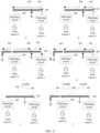
- FIG. 9 is a diagram of current distribution before and after the third radiation branch 303 is added in the antenna system.
- Figure a in FIG. 9 is a diagram of current distribution before the third radiation branch 303 is added when the feed source 2 feeds an N41 frequency band signal through the second feed point 306.
- Figure b in FIG. 9 is a diagram of current distribution before the third radiation branch 303 is added when the feed source 1 feeds an N41 frequency band signal through the first feed point 305. It can be seen from the comparison that, before the third radiation branch 303 is added, current directions of the two feed points when feeding signals are the same, and a common mode (Common mode, C mode) is presented. Still refer to a diagram of current distribution after the third radiation branch 303 is added shown in FIG.
- Figure a in FIG. 10 is a diagram of current distribution after the third radiation branch 303 is added when the feed source 2 feeds an N41 frequency band signal through the second feed point 306.
- Figure b in FIG. 10 is a diagram of current distribution after the third radiation branch 303 is added when the feed source 1 feeds an N41 frequency band signal through the first feed point 305. It can be seen from the comparison that, after the third radiation branch 303 is added, directions of currents fed by the two feed points are opposite, and a form of a differential mode (differential mode, D mode) is presented.
- a diagram of current distribution may be shown in figure c in FIG. 10 .
- the current distribution is uniform, and an effective radiator size is large, which can ensure antenna performance of the antenna system in the medium-frequency band.
- FIG. 11 is a schematic diagram of a current flowing direction in a C-mode form before the third radiation branch 303 is added when the feed source 2 feeds an N41 frequency band signal through the second feed point 306.
- Figure b in FIG. 11 is a schematic diagram of a current flowing direction in a C-mode form before the third radiation branch 303 is added when the feed source 2 feeds an N41 frequency band signal through the second feed point 306.
- FIG. 11 is a schematic diagram of a current flowing direction in a C-mode form before the third radiation branch 303 is added when the feed source 1 feeds an N41 frequency band signal through the first feed point 305. It can be learned that, before the third radiation branch 303 is added, the current directions of the two feed points feeding signals are the same, and the common mode is presented.
- Figure c in FIG. 11 is a schematic diagram of a current flowing direction in a D-mode form after the third radiation branch 303 is added when the feed source 2 feeds an N41 frequency band signal through the second feed point 306.
- FIG. 11 is a schematic diagram of a current flowing direction in a C-mode form after the third radiation branch 303 is added when the feed source 1 feeds an N41 frequency band signal through the first feed point 305. It can be seen from the comparison that, after the third radiation branch 303 is added, directions of currents fed by the two feed points are opposite, and a form of a differential mode is presented. A principle of decoupling is described in figures e and f in FIG. 11 from the perspective of currents. A1 and A2 are current amplitudes of the 1 port and the 2 port, respectively, ⁇ 1 and ⁇ 2 are phases of the 1 port and the 2 port, where a current multiplied by a phase is a magnitude of a coupled current.
- a current coupled from the 1 port to the 2 port is the same as a current coupled from the 2 port to the 1 port.
- the currents are equal in magnitudes and opposite in directions, and can cancel each other and realize decoupling.
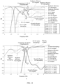
- Figure a in FIG. 12 is a curve comparison diagram of efficiency of a 1-port antenna in an original state and a decoupling state. As shown in figure a in FIG. 12 , at 2.6 GHz, radiation efficiency in a decoupling state is increased by approximately 1 dB when being compared to radiation efficiency in an original state (a point 1 to a point 2). In figure a in FIG. 12 , S 11 is reduced significantly from the original state to the decoupling state by approximately more than 3 dB at 2.6 GHZ, and a total efficiency is increased by approximately 2 dB (a point 6 to a point 5).
- Figure b in FIG. 12 is a curve comparison diagram of efficiency of a 2-port antenna in an original state and a decoupling state.
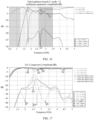
- FIG. 13 is a graph of the envelope correlation coefficients (ECC) of the first radiation branch and the second radiation branch in the original state and the decoupling state, which is described by using the third radiation branch of 12 mm as an example.
- ECC envelope correlation coefficients
- the correlation coefficient in the decoupling state is reduced in the broadband range as a whole.
- the correlation coefficient is reduced to less than 0.05, which indicates that correlation between the first radiation branch and the second radiation branch after decoupling is low, that is, the isolation between the first radiation branch and the second radiation branch is high.
- the length of the third radiation branch can affect the resonance frequency, so that the length of the third radiation branch is controlled to implement canceling of the currents of the C mode and the D mode by each other, and an S21 pit is present in a curve of S21, that is, S21 of a large-isolation frequency band, and the pit position of S21 is to change with the length of the third radiation branch.
- Figure a in FIG. 15 shows graphs of S21 corresponding to the third radiation branch of different lengths when lengths of other radiation branches remain unchanged. It can be seen from FIG.
- corresponding points of corresponding S21 pits are points 7, 6, 5, and 8, and the points 7, 6, 5 and 8 are respectively corresponding to frequencies 3.24 GHz, 2.74 GHz, 2.5 GHz and 1.968 GHz.
- a larger length of the third radiation branch indicates a lower frequency of a decoupling frequency; and a smaller length of the third radiation branch indicates a higher frequency of a decoupling frequency. If a medium-frequency signal is to be decoupled, for example, a signal of 1.71 GHz is decoupled, the length of the third radiation branch may continue to be lengthened from 16 mm.
- the matching form of the first tuning circuit 309 may also be adjusted to fine tune the decoupling frequency.
- the length of the third radiation branch is 12 mm
- parameter curves before and after fine tuning of the first tuning circuit 309 may be shown in figure b in FIG. 15 .
- a dotted line is the parameter curve before adjustment (case0)
- a solid line is the parameter curve after adjustment (case5), it can be seen that S22 variation is not large; S11 is optimized in the medium-frequency band; and S21 is reduced obviously, and a point 4 is reduced from -15 dB before adjustment to -28 dB.
- frequencies of pit points of S21 corresponding to the first radiation branch and the second radiation branch need to be adjusted to lower than a frequency of a pit point of D-mode radiation efficiency generated by the third radiation branch.
- the S21 pits of the first radiation branch and the second radiation branch are at 2.63 GHz
- the frequency of the D-mode radiation efficiency of the third radiation branch is 3.15 GHz
- isolation at a 1 point is -28 dB, which meets a requirement of isolation.
- sizes of the third radiation branch are 8 mm, 10 mm, 12 mm and 16 mm respectively
- frequencies of the pit points of S21 are lower than a frequency of a pit point of D-mode radiation efficiency corresponding to the third radiation branch:
- the corresponding terminal device includes a corresponding hardware for executing the functions.
- the disclosed structure may be implemented in other manners.
- the described structural embodiment is merely an example.
- the module or unit division is merely logical function division and may be other division in actual implementation.
- a plurality of units or components may be combined or integrated into another apparatus, or some features may be ignored or not performed.
- the displayed or discussed mutual couplings or direct couplings or communication connections may be implemented by using some interfaces.
- the indirect couplings or communication connections between the apparatuses or units may be implemented in electronic, mechanical, or other forms.
- the units described as separate parts may or may not be physically separate, and parts displayed as units may be one or more physical units, may be located in one place, or may be distributed on different places. Some or all of the units may be selected based on actual requirements to achieve the objectives of solutions of embodiments.
Landscapes
- Engineering & Computer Science (AREA)
- Computer Networks & Wireless Communication (AREA)
- Physics & Mathematics (AREA)
- Electromagnetism (AREA)
- Variable-Direction Aerials And Aerial Arrays (AREA)
Abstract
Description
- This application claims priority to
Chinese Patent Application No. 202222089717.0, filed with the China National Intellectual Property Administration on August 9, 2022 - This application relates to the field of antenna technologies, and in particular, to an antenna system and a terminal device.
- With rapid development of terminal devices and increasing use requirements of people, terminal devices are increasingly widely used in people's production and life, and communication quality requirements of users on terminal devices are also increasingly high.
- The communication quality of the terminal device depends heavily on performance of a terminal antenna disposed on the terminal device. With popularization of the fifth generation mobile communication technology (5th-Generation, 5G), use demand of a multiple-input multiple-output (multi-input multi-output, MIMO) antenna technology on a terminal device becomes increasingly high. A current terminal device has gradually developed from an antenna system of 2*2 to an antenna system of 4*4. Except for an antenna for wireless fidelity (wireless fidelity, WIFI) and a global positioning system (global positioning system, GPS) at the beginning, 8 to 15 antennas with different functions are usually accommodated on the terminal device.
- In some terminal devices, a full-screen structure solution with an ultra-narrow frame is used, which requires high structure compactness of the terminal device. After the terminal device satisfies the MIMO communication specification, more antennas need to be added, and space of the antenna is further compressed. In the terminal device with a highly-compressed space, a MIMO antenna usually needs to use different antennas to transmit and receive signals of a same frequency band, and consequently, when the signals in the same frequency band are transmitted and received by the different antennas, isolation between the antennas is reduced, and performance of an antenna system is reduced.
- This application provides an antenna system and a terminal device, to improve isolation between antennas, to improve performance of an antenna system and improve communication quality.
- According to a first aspect, an antenna system is provided. The antenna system includes: a first radiation branch, a second radiation branch and a third radiation branch, where the first radiation branch and the second radiation branch are electrically connected, and a first gap is provided between the second radiation branch and the third radiation branch; a first feed point is disposed on the first radiation branch, and the first feed point is located at an end of the first radiation branch away from the second radiation branch; a second feed point is disposed on the second radiation branch, and the second feed point is located at an end of the second radiation branch away from the first radiation branch; the antenna system further includes: a first ground return point, where the first ground return point is located at an electrical connection between the first radiation branch and the second radiation branch, and the first ground return point is located between the first feed point and the second feed point; and a second ground return point is disposed on the third radiation branch, and the second ground return point is located at an end of the third radiation branch away from the first gap.
- In the antenna system, on the basis of the first radiation branch and the second radiation branch, the third radiation branch that can be decoupled is added, and no feed point is provided on the third radiation branch, but the ground return point is arranged, so that the third radiation branch is used as a suspended parasitic radiation branch to influence an excitation mode of the whole antenna system. The third radiation branch is added, so that differential-mode currents are formed on the first radiation branch and the second radiation branch when a
feed source 1 and afeed source 2 feed signals of a same frequency. In this way, some currents on the two radiation branches cancel each other, so that a signal flowing from thefeed source 2 to the first radiation branch is reduced, a signal flowing from thefeed source 1 to the second radiation branch is also reduced, mutual coupling between the two radiation branches is reduced, isolation between the two radiation branches is improved, and decoupling is implemented, to improve performance of the whole antenna system. - In some possible implementations, the first feed point is configured to feed a high-frequency signal, and the second feed point is configured to feed a high-frequency signal and/or a medium-frequency signal.
- In a MIMO scenario, when the
feed source 2 and thefeed source 1 feed high-frequency signals through the second feed point and the first feed point respectively, the third radiation branch is added, so that differential-mode currents can be formed on the first radiation branch and the second radiation branch, some currents on the two radiation branches cancel each other, so that a signal flowing from thefeed source 2 to the first radiation branch is reduced, a signal flowing from thefeed source 1 to the second radiation branch is also reduced, mutual coupling between the two radiation branches in the MIMO scenario is reduced, isolation between the two radiation branches in the MIMO scenario at a high frequency is improved, antenna performance of the whole antenna system in a high-frequency band in the MIMO scenario is improved, and communication quality of the high-frequency band in the MIMO scenario is improved. The second feed point may alternatively feed a medium-frequency signal, so that the second radiation branch may be compatible with a medium-frequency band, and the antenna system supports the high-frequency band while also being compatible with the medium-frequency band, to expand a bandwidth of the antenna system. - In some possible implementations, when the first feed point and the second feed point feed the high-frequency signal, a current mode in the antenna system is a differential mode.
- According to the current mode in the differential mode, some currents on the two radiation branches are canceled, the signal flowing from the
feed source 2 to the first radiation branch is reduced, the signal flowing from thefeed source 1 to the second radiation branch is reduced, mutual coupling between the two radiation branches is reduced, the isolation between the two radiation branches at the high frequency is improved, and the antenna performance of the whole antenna system in the high-frequency band is improved. - In some possible implementations, the high-frequency signal is a signal in an N41 frequency band.
- In the MIMO scenario at the N41 frequency band, the signal flowing from the
feed source 2 to the first radiation branch is reduced, the signal flowing from thefeed source 1 to the second radiation branch is also reduced, mutual coupling between the two radiation branches in the MIMO scenario is reduced, the isolation between the two radiation branches in the MIMO scenario at the N41 frequency band is improved, the antenna performance of the whole antenna system at the N41 frequency band in the MIMO scenario is improved, and communication quality at the N41 frequency band in the MIMO scenario is improved. - In a possible implementation, a length difference between a length of the third radiation branch and a quarter wavelength of the signal in the N41 frequency band is less than a length error threshold.
- The length of the third radiation branch may be a length of a quarter wavelength of a signal fed by the
feed source 2, for example, may be a length equal to the quarter wavelength, or may be a length close to the quarter wavelength, a difference between the length of the third radiation branch and the quarter wavelength is less than a preset length error threshold, and the length error threshold may be 0.5 mm, 1 mm, or the like, to ensure that a resonance state is achieved when the signal is fed, and maintain antenna performance. For example, when thefeed source 1 and thefeed source 2 feed a signal in the N41 frequency band, the length of the third radiation branch may be a length of a quarter of a wavelength corresponding to a center frequency of the N41 frequency band or a length close to the quarter wavelength, to ensure a resonance state. - In a possible implementation, a distance between the first ground return point and the second feed point is greater than a distance between the first feed point and the first ground return point.
- A length that is of the second radiation branch and that is provided when the second radiation branch is used as a main radiation branch when the
feed source 2 feeds a signal is greater than a length that is of the first radiation branch and that is provided when the first radiation branch is used as a main radiation branch when thefeed source 1 feeds a signal. Therefore, in a resonant mode, a frequency band that matches the second radiation branch between the first ground return point and the second feed point is lower than a frequency band that matches the first radiation branch between the first feed point and the first ground return point, and the second radiation branch can be compatible with the medium-frequency band, so that the antenna system is compatible with the medium-frequency band while supporting the high-frequency band, to expand the bandwidth of the antenna system. - In a possible implementation, the second ground return point is located at an end of the third radiation branch away from the first gap, and a length of the third radiation branch is greater than a distance between an end of the second radiation branch close to the first gap to the second feed point.
- When the second ground return point is located at the end of the third radiation branch away from the first gap, if the length of the third radiation branch is too short, a resonant frequency corresponding to a case in which a current mode excited by the antenna system is the differential mode is too high. In this case, if the length of the third radiation branch is greater than the distance between the end of the second radiation branch close to the first gap to the second feed point, that a resonance frequency of the third radiation branch and a frequency band at which decoupling is required can be matched can be ensured, to ensure decoupling effect.
- In a possible implementation, a first tuning circuit is further disposed on the third radiation branch, and an end of the third radiation branch close to the first gap is grounded through the first tuning circuit.
- The first tuning circuit is disposed, so that a ground return tuning point can be added on the third radiation branch, so that a tuning capability of the antenna system is improved, and therefore the performance of the antenna system can be further improved.
- In a possible implementation, a second tuning circuit is further disposed on the second radiation branch, the second tuning circuit is located between the second feed point and the first ground return point, and the second radiation branch is grounded through the second tuning circuit.
- The second tuning circuit is disposed, so that a tuning point can be added on the second radiation branch, the tuning capability of the antenna system is improved, and therefore the performance of the antenna system can be further improved.
- In some possible implementations, the antenna system further includes a third tuning circuit, and the first feed point is grounded through the third tuning circuit.
- In some possible implementations, the antenna system further includes a fourth tuning circuit, and the second feed point is grounded through the fourth tuning circuit.
- The third tuning circuit and/or the fourth tuning circuit are/is disposed, so that the tuning capability of the antenna system is improved, and therefore the performance of the antenna system can be further improved.
- In some possible implementations, a shape of the first radiation branch is L-shaped.
- The first radiation branch of the L-shaped structure is used, so that an antenna size can be reduced and an antenna layout is facilitated while the antenna size is maintained.
- According to a second aspect, a terminal device is provided. The terminal device includes the antenna systems according to any one of the technical solutions of the first aspect.
-
-
FIG. 1 is a schematic diagram of a structure of a terminal device according to an embodiment of this application; -
FIG. 2 is a schematic diagram of a common antenna system and a corresponding S parameter graph. -
FIG. 3 is a schematic diagram of a structure of an antenna system according to an embodiment of this application; -
FIG. 4 is a schematic diagram in which an S parameter graph of an antenna system according to an embodiment of this application is compared with an S parameter graph of a conventional antenna system; -
FIG. 5 is a schematic diagram of structures of antenna systems in different structures according to an embodiment of this application; -
FIG. 6 is a schematic diagram of a structure of an antenna system in a different tuning form according to an embodiment of this application; -
FIG. 7 is a schematic diagram of a structure of an antenna system in a different tuning form according to an embodiment of this application; -
FIG. 8 is a schematic diagram of a structure of an antenna system in a different tuning form according to an embodiment of this application; -
FIG. 9 is a diagram of current distribution of a common antenna system during feeding; -
FIG. 10 is a diagram of current distribution of an antenna system during feeding according to an embodiment of this application; -
FIG. 11 is a schematic diagram of current distribution of an antenna system before and after a third radiation branch is added according to an embodiment of this application; -
FIG. 12 is a parameter curve comparison diagram of an antenna system before and after a third radiation branch is added according to an embodiment of this application; -
FIG. 13 is a correlation coefficient curve comparison diagram of a first radiation branch and a second radiation branch before and after a third radiation branch is added according to an embodiment of this application; -
FIG. 14 is an antenna direction comparison diagram before and after a third radiation branch is added according to an embodiment of this application; -
FIG. 15 is an S parameter curve comparison diagram of an antenna system when a third radiation branch of different lengths is used according to an embodiment of this application; -
FIG. 16 is a schematic diagram in which frequencies of pit points of S21 corresponding to a first radiation branch and a second radiation branch are lower than a frequency of a pit point of D-mode radiation efficiency generated by a third radiation branch according to an embodiment of this application; and -
FIG. 17 is a schematic diagram in which frequencies of pit points of S21 corresponding to a first radiation branch and a second radiation branch are lower than a frequency of a pit point of D-mode radiation efficiency generated by a third radiation branch when a third radiation branch of different lengths is used according to an embodiment of this application. - Technical solutions in embodiments of this application are described below with reference to the accompanying drawings of the following embodiments of this application. In descriptions of embodiments of this application, "/" indicates "or", unless otherwise specified. For example, A/B may indicate A or B; and the term "and/or" in this specification describes only an association relationship between associated objects and indicates that three relationships may exist. For example, A and/or B may represent the following three cases: Only A exists, both A and B exist, and only B exists. In addition, in the description of embodiments of this application, "a plurality of" means "two or more".
- The following terms "first", "second", and "third" are merely intended for a purpose of description, and shall not be understood as an indication or implication of relative importance or implicit indication of the number of indicated technical features. Therefore, a feature limited by "first", "second", and "third" may explicitly or implicitly include one or more features.
- An antenna system in embodiments of this application may be applied to a terminal device, for example, a mobile phone, a tablet computer, a wearable device, a vehicle-mounted device, an augmented reality (augmented reality, AR)/virtual reality (virtual reality, VR) device, a notebook computer, an ultra-mobile personal computer (ultra-mobile personal computer, UMPC), a netbook, or a personal digital assistant (personal digital assistant, PDA). A specific type of the terminal device is not limited in embodiments of this application.
-
FIG. 1 is a schematic structural diagram of aterminal device 100 according to an embodiment of this application. As shown in figure a inFIG. 1 , theterminal device 100 provided in this embodiment of this application may be provided with a screen andcover plate 101, a metal housing 102, aninternal structure 103, and arear cover 104 in sequence along a z-axis from top to bottom. - The screen and
cover plate 101 may be configured to implement a display function of theterminal device 100. The metal housing 102 may be used as a main framework of theterminal device 100 to provide rigid support for theterminal device 100. Theinternal structure 103 may include a collection of electronic components and mechanical components that implement various functions of theterminal device 100. For example, theinternal structure 103 may include a shielding cover, screws, strengthening ribs, and the like. Therear cover 104 may be an exterior surface of the back of theterminal device 100. Therear cover 104 may be made of a glass material, a ceramic material, plastic, and the like in different implementations. - An antenna system provided in an embodiment of this application can be applied in the
terminal device 100 shown in figure a inFIG. 1 to support wireless communication function of theterminal device 100. In some embodiments, the antenna system may be arranged on the metal housing 102 of theterminal device 100. In some other embodiments, the antenna system involved in the antenna solution may be arranged on therear cover 104 of theterminal device 100, or the like. - As an example, taking the metal housing 102 having a metal frame structure as an example, b and c in
FIG. 1 show a schematic composition of the metal housing 102. A figure b inFIG. 1 shows an example in which the antenna system is arranged on a short side of the terminal device, and a figure c inFIG. 1 shows an example in which the antenna system is arranged on a long side of the terminal device. Certainly, the antenna system may alternatively be disposed on a short side of the terminal device and a long side adjacent to the short side. The figure b inFIG. 1 is used as an example for description, and the metal housing 102 may be made of a metal material such as aluminum alloy. As shown in figure b inFIG. 1 , a reference ground may be arranged on the metal housing 102. The reference ground may be a metal material with a large area, which is used to provide most of the rigid support, while providing a zero potential reference for various electronic components. In the example shown in figure b inFIG. 1 , a metal frame may further be arranged on a periphery of the reference ground. The metal frame may be a complete and closed metal frame, and the metal frame may include a partially or completely suspended metal strip. In some other implementations, the metal frame may alternatively be a metal frame interrupted by one or more gaps as shown in figure b inFIG. 1 . For example, in the example of figure b inFIG. 1 , agap 1, agap 2, and agap 3 may be provided at different positions of the metal frame. These gaps can break the metal frame to obtain individual metal branches. In some embodiments, some or all of these metal branches can be used as antenna radiation branches, to implement structural reuse during antenna disposing and reduce difficulty of antenna disposing. When the metal branch is used as an antenna radiation branch, a position of a gap corresponding to one end of the metal branch or positions of gaps corresponding to two ends of the metal branch can be flexibly selected based on antenna disposing. - In the example shown in figure b in
FIG. 1 , one or more metal pins may further be arranged on the metal frame. In some examples, the metal pins may be provided with screw holes for securing other structural parts by screws. In other examples, the metal pin may be coupled to a feed point to feed an antenna through the metal pin when the metal branch connected to the metal pin is used as a radiation branch of the antenna. In some other examples, the metal pins may alternatively be connected to other electronic components through coupling to achieve corresponding electrical connection functions. In this embodiment of this application, in figure b and figure c inFIG. 1 , the metal pin may be coupled to the feed point or may be grounded. - In this example, configuration of a printed circuit board (printed circuit board, PCB) on the metal housing is also shown. A main board (main board) and a sub board (sub board) of a board split design are taken as an example. In other examples, the main board and the sub board may alternatively be connected of, for example, an L-PCB design. In some embodiments of this application, the main board (for example, a PCB 1) may be configured to carry electronic components that implement various functions of the
terminal device 100, such as a processor, a memory, a radio frequency module. The sub board (such as a PCB 2) may alternatively be used to carry electronic components, such as a universal serial bus (universal serial bus, USB) interface and a related circuit, and a speak box (speak box). For another example, the sub board may further be configured to carry a radio frequency circuit or the like corresponding to an antenna arranged at the bottom (that is, a part in a negative direction of a y-axis of the terminal device). - It should be noted that the various radiation branches mentioned below (a first radiation branch, a second radiation branch, a third radiation branch, a
radiation branch 1, aradiation branch 2 and aradiation branch 3, and the like) and various radiation bodies are the metal radiation branches mentioned above. - With rapid development of terminal devices and increasing use requirements of people, terminal devices are increasingly widely used in people's production and life, and communication quality requirements of users on terminal devices are also increasingly high.
- The communication quality of the terminal device depends heavily on performance of a terminal antenna disposed on the terminal device. With popularization of 5G, use demand of a MIMO antenna technology on a terminal device becomes increasingly high. Currently, an antenna system of 2*2 to an antenna system of 4*4 have been gradually developed. Except for an antenna for WIFI and a GPS at the beginning, 8 to 15 antennas with different functions are usually accommodated on the terminal device.
- In some terminal devices, a full-screen structure solution with an ultra-narrow frame is used, which requires high structure compactness of the terminal device. After the terminal device satisfies the MIMO communication specification, more antennas need to be added, and space of the antenna is further compressed. In the terminal device with a highly-compressed space, a MIMO antenna usually needs to use different antennas to transmit and receive signals of a same frequency band, and consequently, when the signals in the same frequency band are transmitted and received by the different antennas, isolation between the antennas is reduced, and performance of an antenna system is reduced.
- Refer to a structure shown in a in
FIG. 2 . A common MIMO antenna includes anantenna 1 and anantenna 2. Afeed point 1 is disposed on theantenna 1, and thefeed point 1 may be connected to a feed source a; afeed point 2 is disposed on theantenna 2, and thefeed point 2 may be connected to a feed source b; and theantenna 1 and theantenna 2 are grounded through a same ground return point. For example, a signal in an N41 frequency band is radiated. When the two feed points respectively feed signals in the N41 frequency band (2.6 GHz), a curve (S12) of isolation between the two antennas can be seen in figure b inFIG. 2 , which is only -8 decibels (dB). This cannot meet requirement of antenna performance. - In the technical solution of this application, an excitation mode is changed by adding a parasitic branch used for decoupling in an original antenna system and disposing a gap between the original antennas. When the antenna is in an excited state, due to the added parasitic radiation branch, differential mode currents can be generated on the original two antennas, so that some currents distributed on the original two antennas are canceled, so that a signal flowing from the feed source a to the
antenna 2 is reduced, a signal flowing from the feed source b to theantenna 1 is also reduced, mutual coupling between the two antennas is reduced, and the isolation between the two antennas is improved. -
FIG. 3 is a schematic diagram of a structure of an antenna system according to an embodiment of this application. According to the above antenna solution, athird radiation branch 303 for decoupling is added in the antenna system, and the addedthird radiation branch 303 can change a current mode in the antenna system and improve isolation between different antennas. As shown inFIG. 3 , the antenna system includes afirst radiation branch 301, asecond radiation branch 302, and athird radiation branch 303. Thefirst radiation branch 301 and thesecond radiation branch 302 are electrically connected, and thefirst radiation branch 301 and thesecond radiation branch 302 are of an integral structure connected together structurally with different functions and effects as two radiators. Thethird radiation branch 303 and thesecond radiation branch 302 are sequentially arranged along a length direction, and afirst gap 304 is provided between thesecond radiation branch 302 and thethird radiation branch 303. - A
first feed point 305 is disposed on thefirst radiation branch 301, and thefirst feed point 305 is located at an end of thefirst radiation branch 301 away from thesecond radiation branch 302. Asecond feed point 306 is disposed on thesecond radiation branch 302, and thesecond feed point 306 is located at an end of thesecond radiation branch 302 away from thefirst radiation branch 301. The antenna system further includes: a firstground return point 307, the firstground return point 307 is located at an electrical connection between thefirst radiation branch 301 and thesecond radiation branch 302, and the firstground return point 307 is located between thefirst feed point 305 and thesecond feed point 306. Thefirst radiation branch 301 and thesecond radiation branch 302 share the firstground return point 307. A secondground return point 308 is disposed on thethird radiation branch 303, and the secondground return point 308 is located at an end of thethird radiation branch 303 away from thefirst gap 304. - In the antenna system shown in
FIG. 3 , thefirst feed point 305 may be connected to thefeed source 1, and thesecond feed point 306 may be connected to thefeed source 2. Optionally, the feed point and the feed source may be directly connected, or may be connected through a series capacitor, or may be connected through a matching circuit in another matching form, which is not limited in this embodiment of this application. - In the antenna system shown in
FIG. 3 , on the basis of thefirst radiation branch 301 and thesecond radiation branch 302, thethird radiation branch 303 that can be decoupled is added, and no feed point is provided on thethird radiation branch 303, but the ground return point is arranged, so that thethird radiation branch 303 is used as a suspended parasitic radiation branch to influence an excitation mode of the whole antenna system. Thethird radiation branch 303 is added, so that differential-mode currents are formed on thefirst radiation branch 301 and thesecond radiation branch 302 when afeed source 1 and afeed source 2 feed signals of a same frequency. In this way, some currents on the two radiation branches cancel each other, so that a signal flowing from thefeed source 2 to thefirst radiation branch 301 is reduced, a signal flowing from thefeed source 1 to thesecond radiation branch 302 is also reduced, mutual coupling between the two radiation branches is reduced, isolation between the two radiation branches is improved, and decoupling is implemented, to improve performance of the whole antenna system. - Optionally, the
feed source 2 may feed low-frequency signals through thesecond feed point 306, such as low-frequency signals in bands such as B5 and B8; or may feed medium-frequency signals, such as medium-frequency signals in frequency bands such as B1, B2, and B3, or may feed high-frequency signals in frequency bands such as B7 and B41. Thefeed source 1 may feed low-frequency signals through thefirst feed point 305, such as low-frequency signals in bands such as B5 and B8; or may feed medium-frequency signals, such as medium-frequency signals in frequency bands such as B1, B2, and B3, or may feed high-frequency signals in frequency bands such as B7 and B41. A frequency band of a fed signal is not limited in this embodiment of this application. - In some embodiments, the
feed source 2 may feed high-frequency signals through thesecond feed point 306, such as signals in bands such as B7 and N41; or may feed medium-frequency signals, such as signals in frequency bands such as B1, B2, and B3. Thefeed source 1 may feed a high-frequency signal through thefirst feed point 305. In a MIMO scenario, when thefeed source 2 and thefeed source 1 feed high-frequency signals respectively, thethird radiation branch 303 is added, so that differential-mode currents can be formed on thefirst radiation branch 301 and thesecond radiation branch 302, some currents on the two radiation branches cancel each other, so that a signal flowing from thefeed source 2 to thefirst radiation branch 301 is reduced, a signal flowing from thefeed source 1 to thesecond radiation branch 302 is also reduced, mutual coupling between the two radiation branches in the MIMO scenario is reduced, isolation between the two radiation branches in the MIMO scenario at a high frequency is improved, antenna performance of the whole antenna system in a high-frequency band in the MIMO scenario is improved, and communication quality of the high-frequency band in the MIMO scenario is improved. - The technical effects of embodiments of this application are described below with reference to antenna parameters of a specific embodiment. For example, in an embodiment of this application, a port of the antenna system connected to the
feed source 2 is a 1 port, and a port of the antenna system connected to thefeed source 1 is a 2 port. It should be noted that S12 and S21 are forward transmission coefficients. S21 is used as an example, S21 represents a magnitude of energy transmitted from the 2 port to the 1 port. When S21 is used to indicate isolation, a smaller value indicates larger isolation. S11 and S22 are the reflection systems of the 1 port and the 2 port respectively, and larger S11 and S22 indicate larger energy reflected by the corresponding ports. Larger energy reflected by the port indicates larger energy loss and a lower matching degree; and conversely, smaller S11 and S22 indicate less energy reflected by the corresponding ports, smaller energy loss, and a higher matching degree. -
FIG. 4 is a comparison diagram of S parameter curves obtained before and after thethird radiation branch 303 for decoupling is added in the antenna system. For ease of marking, the S parameter curve obtained after adding the third radiation branch is marked as: decoupling, and the S parameter curve obtained before adding the third radiation branch is marked as: original. It can be seen fromFIG. 4 that, after thethird radiation branch 303 is added in the antenna system, the value of the isolation (S21) is reduced by a large amplitude, original -8.7675 dB (a marked point 6) is reduced to -16.202 dB (a marked point 5) at 2.6 GHz, and the isolation is reduced by more than 7 dB. It can be further seen fromFIG. 4 that after thethird radiation branch 303 is added, a large pit in a medium-frequency band appears in the S11 curve, indicating that energy loss of the medium-frequency band is reduced. S11 is lowered in a frequency band range of 2.5 GHz to 2.7 GHz (specifically, between amark point 2 and a mark point 3), indicating that energy loss of a high-frequency band is also reduced. Amark point 1 is a 1.71 GHz frequency that has a reflection coefficient of -7.4962 dB, and an S11 at this frequency is reduced. As shown inFIG. 4 , S22 does not change sharply and does not deteriorate. - Optionally, on the basis of the foregoing embodiments, a distance between the first
ground return point 307 and thesecond feed point 306 is greater than a distance between thefirst feed point 305 and the firstground return point 307. Still refer toFIG. 3 . A length that is of thesecond radiation branch 302 and that is provided when thesecond radiation branch 302 is used as a main radiation branch when thefeed source 2 feeds a signal is greater than a length that is of thefirst radiation branch 301 and that is provided when thefirst radiation branch 301 is used as a main radiation branch when thefeed source 1 feeds a signal. Therefore, in a resonant mode that matches a quarter wavelength, a frequency band that matches thesecond radiation branch 302 between the firstground return point 307 and thesecond feed point 306 is lower than a frequency band that matches thefirst radiation branch 301 between thefirst feed point 305 and the firstground return point 307, and thesecond radiation branch 302 can be compatible with the medium-frequency band, so that the antenna system is compatible with the medium-frequency band while supporting the high-frequency band, to expand the bandwidth of the antenna system. - Optionally, the second
ground return point 308 may be located at an end of thethird radiation branch 303 away from thefirst gap 304, for example, may be at a specific distance from the end of thethird radiation branch 303 away from thefirst gap 304, for example, of a smaller size, such as 1 mm and 0.5 mm away from the end of thethird radiation branch 303 away from the first gap. The secondground return point 308 may alternatively be located at an end of thethird radiation branch 303 away from thefirst gap 304, for example, as shown inFIG. 5 . Figure a inFIG. 5 shows a structure in which the secondground return point 308 is located at the end away from thefirst gap 304 when thethird radiation branch 303 is an I-shaped structure. In addition, when the secondground return point 308 is located at the end of thethird radiation branch 303 away from the first gap, if the length of thethird radiation branch 303 is too short, a resonant frequency corresponding to a case in which a current mode excited by the antenna system is a differential mode is too high. In this case, if the length of thethird radiation branch 303 is greater than a distance between an end of thesecond radiation branch 302 close to thefirst gap 304 to thesecond feed point 306, that a resonance frequency of thethird radiation branch 303 and a frequency band at which decoupling is required can be matched can be ensured, to ensure decoupling effect. - In some embodiments, the
third radiation branch 303 may also be an "L"-shaped structure as shown in b inFIG. 5 , such radiation branch of the L-shaped structure is used, so that an antenna size can be reduced and facilitate an antenna layout while the antenna size is maintained. Optionally, thefirst radiation branch 301 may also be an "L"-shaped structure. For example, as shown in figure c inFIG. 5 , due to such a structure, an antenna size can be reduced and an antenna layout is facilitated while the antenna size is maintained. In the antenna system, whether to set thefirst radiation branch 301 to the "L"-shaped structure or thethird radiation branch 303 to the "L"-shaped structure is determined based on a specific location in the terminal device, for example, a location close to a left side or close to a right side. - Optionally, on the basis of the foregoing embodiment, the length of the
third radiation branch 303 may be a length of a quarter wavelength of a signal fed by thefeed source 2, for example, may be a length equal to the quarter wavelength, or may be a length close to the quarter wavelength, a difference between the length of thethird radiation branch 303 and the quarter wavelength is less than a preset length error threshold, and the length error threshold may be 0.5 mm, 1 mm, or the like, to ensure that a resonance state is achieved when the signal is fed, and maintain antenna performance. For example, when thefeed source 1 and thefeed source 2 feed a signal in the N41 frequency band, the length of thethird radiation branch 303 may be a length of a quarter of a wavelength corresponding to a center frequency of the N41 frequency band. Usually, the length of thethird radiation branch 303 is adjusted to match different frequencies. For example, the length of thethird radiation branch 303 may be reduced to adapt to a signal with a high frequency. When a signal with a low frequency needs to be adapted, the length of thethird radiation branch 303 may be increased, so that the length of thethird radiation branch 303 remains near a quarter wavelength of an excitation signal to ensure a resonance state. - Optionally, based on the foregoing embodiments, refer to the antenna system in
FIG. 6 . Afirst tuning circuit 309 may be disposed on thethird radiation branch 303, and an end of thethird radiation branch 303 close to thefirst gap 304 is grounded through thefirst tuning circuit 309. Thefirst tuning circuit 309 may be a microstrip line with a fixed width and length, or may be a microstrip line with a changed width and length, or may be a form of an LC filter circuit, for example, may include any one or a combination of a series capacitor, a parallel capacitor, a series inductor, a parallel inductor, and the like. A specific form of thefirst tuning circuit 309 is not limited in this embodiment of this application. Optionally, thefirst tuning circuit 309 may alternatively be a structure in which a plurality of switches are connected to different matching forms, and thefirst tuning circuit 309 may alternatively be an electronic tuner (Tuner). InFIG. 6 , thefirst tuning circuit 309 with a T-shaped structure tuning circuit as an example is illustrated, and in fact, the tuning circuit can be adjusted based on an actual situation, and a capacitance value and an inductance value in the tuning circuit are not limited. Thefirst tuning circuit 309 is disposed, so that a ground return tuning point can be added on thethird radiation branch 303, so that a tuning capability of the antenna system is improved, and therefore the performance of the antenna system can be further improved. - Based on the foregoing embodiments, a
second tuning circuit 310 is further disposed on thesecond radiation branch 302. Refer to a structure of the antenna system shown inFIG. 7 , thesecond tuning circuit 310 is located between thesecond feed point 306 and the firstground return point 307, and thesecond radiation branch 306 is grounded through thesecond tuning circuit 310. The implementation of thesecond tuning circuit 310 may be a microstrip line with a fixed width and length, or may be a microstrip line with a changed width and length, or may be a form of an LC filter circuit, for example, may include any one or a combination of a series capacitor, a parallel capacitor, a series inductor, a parallel inductor, and the like. Optionally, thesecond tuning circuit 310 may alternatively be a structure in which a plurality of switches are connected to different matching forms, and thesecond tuning circuit 310 may alternatively be an electronic tuner (Tuner). A specific form of thesecond tuning circuit 310 is not limited in this embodiment of this application. InFIG. 7 , the tuning circuit with thefirst tuning circuit 310 as an L-shaped structure is illustrated, and in fact, the tuning circuit can be debugged according to an actual situation, and the capacitance value and the inductance value in the tuning circuit are not limited. Thesecond tuning circuit 310 is disposed, so that a tuning point can be added on thesecond radiation branch 302, the tuning capability of the antenna system is improved, and therefore the performance of the antenna system can be further improved. - Refer to
FIG. 8 . Optionally, based on the foregoing embodiments, the structure of the antenna system may further include thethird tuning circuit 311, and thefirst feed point 305 is grounded through thethird tuning circuit 311. Optionally, refer toFIG. 8 . The antenna system further includes afourth tuning circuit 312, and thesecond feed point 306 is grounded through thefourth tuning circuit 312. For implementations of thethird tuning circuit 311 and thefourth tuning circuit 312, refer to descriptions of thefirst tuning circuit 309 and thesecond tuning circuit 310. InFIG. 8 , thethird tuning circuit 311 is a structure in which different matching forms are connected, and the fourth tuning circuit is a connecting electronic tuner as an example. Thethird tuning circuit 311 and/or thefourth tuning circuit 312 are/is disposed, so that the tuning capability of the antenna system is improved, and therefore the performance of the antenna system can be further improved. - To describe an implementation principle of the technical solutions of this application more clearly, how to solve the technical problems according to embodiments of this application is described in detail with reference to a change of current distribution in a specific embodiment.
- As shown in
FIG. 9, FIG. 9 is a diagram of current distribution before and after thethird radiation branch 303 is added in the antenna system. Figure a inFIG. 9 is a diagram of current distribution before thethird radiation branch 303 is added when thefeed source 2 feeds an N41 frequency band signal through thesecond feed point 306. Figure b inFIG. 9 is a diagram of current distribution before thethird radiation branch 303 is added when thefeed source 1 feeds an N41 frequency band signal through thefirst feed point 305. It can be seen from the comparison that, before thethird radiation branch 303 is added, current directions of the two feed points when feeding signals are the same, and a common mode (Common mode, C mode) is presented. Still refer to a diagram of current distribution after thethird radiation branch 303 is added shown inFIG. 10 . Figure a inFIG. 10 is a diagram of current distribution after thethird radiation branch 303 is added when thefeed source 2 feeds an N41 frequency band signal through thesecond feed point 306. Figure b inFIG. 10 is a diagram of current distribution after thethird radiation branch 303 is added when thefeed source 1 feeds an N41 frequency band signal through thefirst feed point 305. It can be seen from the comparison that, after thethird radiation branch 303 is added, directions of currents fed by the two feed points are opposite, and a form of a differential mode (differential mode, D mode) is presented. After thethird radiation branch 303 is added and a signal of a medium-frequency band is fed from thesecond feed point 306, a diagram of current distribution may be shown in figure c inFIG. 10 . The current distribution is uniform, and an effective radiator size is large, which can ensure antenna performance of the antenna system in the medium-frequency band. - In order to clearly describe a current flow direction, the diagrams of current distribution shown in
FIG. 9 andFIG. 10 are abstracted into a current distribution schematic diagram, as shown inFIG. 11 . A dotted arrow inFIG. 11 represents a flow direction of a current in a corresponding state, a thick dotted line represents a larger current, and a thin dotted line represents a smaller current. Figure a inFIG. 11 is a schematic diagram of a current flowing direction in a C-mode form before thethird radiation branch 303 is added when thefeed source 2 feeds an N41 frequency band signal through thesecond feed point 306. Figure b inFIG. 11 is a schematic diagram of a current flowing direction in a C-mode form before thethird radiation branch 303 is added when thefeed source 1 feeds an N41 frequency band signal through thefirst feed point 305. It can be learned that, before thethird radiation branch 303 is added, the current directions of the two feed points feeding signals are the same, and the common mode is presented. Figure c inFIG. 11 is a schematic diagram of a current flowing direction in a D-mode form after thethird radiation branch 303 is added when thefeed source 2 feeds an N41 frequency band signal through thesecond feed point 306. Figure d inFIG. 11 is a schematic diagram of a current flowing direction in a C-mode form after thethird radiation branch 303 is added when thefeed source 1 feeds an N41 frequency band signal through thefirst feed point 305. It can be seen from the comparison that, after thethird radiation branch 303 is added, directions of currents fed by the two feed points are opposite, and a form of a differential mode is presented. A principle of decoupling is described in figures e and f inFIG. 11 from the perspective of currents. A1 and A2 are current amplitudes of the 1 port and the 2 port, respectively, Φ1 and Φ2 are phases of the 1 port and the 2 port, where a current multiplied by a phase is a magnitude of a coupled current. When A1e jφ1 = A2e jφ2 , a current coupled from the 1 port to the 2 port is the same as a current coupled from the 2 port to the 1 port. At this time, the currents are equal in magnitudes and opposite in directions, and can cancel each other and realize decoupling. - The technical effects of embodiments of this application may alternatively be described by using other parameters.
- Figure a in
FIG. 12 is a curve comparison diagram of efficiency of a 1-port antenna in an original state and a decoupling state. As shown in figure a inFIG. 12 , at 2.6 GHz, radiation efficiency in a decoupling state is increased by approximately 1 dB when being compared to radiation efficiency in an original state (apoint 1 to a point 2). In figure a inFIG. 12 ,S 11 is reduced significantly from the original state to the decoupling state by approximately more than 3 dB at 2.6 GHZ, and a total efficiency is increased by approximately 2 dB (apoint 6 to a point 5). Figure b inFIG. 12 is a curve comparison diagram of efficiency of a 2-port antenna in an original state and a decoupling state. As shown in figure b inFIG. 12 , S22 is not changed significantly from the original state to the decoupling state at 2.6 GHz. As shown in figure b inFIG. 12 , radiation efficiency in a decoupling state is increased by approximately 0.9 dB when being compared to radiation efficiency in an original state (apoint 2 to a point 3). A total efficiency is increased from -1.9 to -1.3, and a total efficiency is increased by approximately 0.6 dB (apoint 4 to a point 5). - From the perspective of correlation,
FIG. 13 is a graph of the envelope correlation coefficients (ECC) of the first radiation branch and the second radiation branch in the original state and the decoupling state, which is described by using the third radiation branch of 12 mm as an example. As shown inFIG. 13 , the correlation coefficient in the decoupling state is reduced in the broadband range as a whole. Particularly, at 0.3 and 0.4 of the original state between 2.4 GHz -2.6 GHz, the correlation coefficient is reduced to less than 0.05, which indicates that correlation between the first radiation branch and the second radiation branch after decoupling is low, that is, the isolation between the first radiation branch and the second radiation branch is high. - In terms of antenna pattern analysis, in the original state, in
FIG. 14 , when N41 signals are fed by the two feed points, high-gain directions of the antenna pattern are close to each other, shown as an illustrated lower right direction (a direction facing the paper). In this case, independence between the first radiation branch and the second radiation branch is low, and the isolation is also low. In the decoupling state, when the second feed point feeds the N41 signal, a high-gain direction of a corresponding antenna pattern is changed from the lower right direction to a lower left direction, and the high-gain direction of the antenna pattern is different from the high-gain direction of the antenna pattern obtained when the first feed point feeds the N41 signal. In this case, independence between the first radiation branch and the second radiation branch is improved, and the isolation is also improved. - Next, influence of a size of each radiation branch on the antenna performance is described with reference to graphs.
- As mentioned above, the length of the third radiation branch can affect the resonance frequency, so that the length of the third radiation branch is controlled to implement canceling of the currents of the C mode and the D mode by each other, and an S21 pit is present in a curve of S21, that is, S21 of a large-isolation frequency band, and the pit position of S21 is to change with the length of the third radiation branch. Refer to figure a in
FIG. 15 . Figure a inFIG. 15 shows graphs of S21 corresponding to the third radiation branch of different lengths when lengths of other radiation branches remain unchanged. It can be seen fromFIG. 15 that when the length of the third radiation branch is 8 mm, 10 mm, 12 mm and 16 mm respectively, corresponding points of corresponding S21 pits arepoints points - After the length of the third radiation branch is determined, the matching form of the
first tuning circuit 309 may also be adjusted to fine tune the decoupling frequency. For example, it is determined that the length of the third radiation branch is 12 mm, and parameter curves before and after fine tuning of thefirst tuning circuit 309 may be shown in figure b inFIG. 15 . In figure b inFIG. 15 , a dotted line is the parameter curve before adjustment (case0), a solid line is the parameter curve after adjustment (case5), it can be seen that S22 variation is not large; S11 is optimized in the medium-frequency band; and S21 is reduced obviously, and apoint 4 is reduced from -15 dB before adjustment to -28 dB. - During adjustment, frequencies of pit points of S21 corresponding to the first radiation branch and the second radiation branch need to be adjusted to lower than a frequency of a pit point of D-mode radiation efficiency generated by the third radiation branch. As shown in
FIG. 16 , the S21 pits of the first radiation branch and the second radiation branch are at 2.63 GHz, the frequency of the D-mode radiation efficiency of the third radiation branch is 3.15 GHz, and isolation at a 1 point is -28 dB, which meets a requirement of isolation. Still refer toFIG. 17 . When sizes of the third radiation branch are 8 mm, 10 mm, 12 mm and 16 mm respectively, frequencies of the pit points of S21 are lower than a frequency of a pit point of D-mode radiation efficiency corresponding to the third radiation branch: - When the third radiation branch is 8 mm, a frequency (3.25 GHz) of
S21 Mark 3 < a frequency (4.49 GHz) of Mark 7 (a lowest point of D mode); - when the third radiation branch is 10 mm, a frequency (2.74 GHz) of
S21 Mark 2 < a frequency (3 GHz) of Mark 6 (a lowest point of D mode); - when the third radiation branch is 12 mm, a frequency (2.5 GHz) of
S21 Mark 1 < a frequency (2.8 GHz) of Mark 5 (a lowest point of D mode); and - when the third radiation branch is 16 mm, a frequency (1.97 GHz) of
S21 Mark 4 < a frequency (2.2 GHz) of Mark 8 (a lowest point of D mode). - The above describes in detail the examples of the antenna system provided in this application. It can be understood that, to implement the foregoing functions, the corresponding terminal device includes a corresponding hardware for executing the functions.
- In the several embodiments provided in this application, it should be understood that the disclosed structure may be implemented in other manners. For example, the described structural embodiment is merely an example. For example, the module or unit division is merely logical function division and may be other division in actual implementation. For example, a plurality of units or components may be combined or integrated into another apparatus, or some features may be ignored or not performed. In addition, the displayed or discussed mutual couplings or direct couplings or communication connections may be implemented by using some interfaces. The indirect couplings or communication connections between the apparatuses or units may be implemented in electronic, mechanical, or other forms.
- The units described as separate parts may or may not be physically separate, and parts displayed as units may be one or more physical units, may be located in one place, or may be distributed on different places. Some or all of the units may be selected based on actual requirements to achieve the objectives of solutions of embodiments.
- The foregoing descriptions are merely specific implementations of this application, but the protection scope of this application is not limited thereto. Any variation or replacement readily figured out by a person skilled in the art within the technical scope disclosed in this application shall fall within the protection scope of this application. Therefore, the protection scope of this application shall be subject to the protection scope of the claims.
Claims (13)
- An antenna system, comprising: a first radiation branch, a second radiation branch and a third radiation branch, whereinthe first radiation branch and the second radiation branch are electrically connected, and a first gap is provided between the second radiation branch and the third radiation branch;a first feed point is disposed on the first radiation branch, and the first feed point is located at an end of the first radiation branch away from the second radiation branch;a second feed point is disposed on the second radiation branch, and the second feed point is located at an end of the second radiation branch away from the first radiation branch;the antenna system further comprises: a first ground return point, wherein the first ground return point is located at an electrical connection between the first radiation branch and the second radiation branch, and the first ground return point is located between the first feed point and the second feed point; anda second ground return point is disposed on the third radiation branch, and the second ground return point is located at an end of the third radiation branch away from the first gap.
- The antenna system according to claim 1, wherein the first feed point is configured to feed a high-frequency signal, and the second feed point is configured to feed a high-frequency signal and / or a medium-frequency signal.
- The antenna system according to claim 2, wherein when the first feed point and the second feed point feed the high-frequency signal, a current mode in the antenna system is a differential mode.
- The antenna system according to claim 2 or claim 3, wherein the high-frequency signal is a signal in an N41 frequency band.
- The antenna system according to claim 4, wherein a length difference between a length of the third radiation branch and a quarter wavelength of the signal in the N41 frequency band is less than a length error threshold.
- The antenna system according to any one of claims 1 to 3, wherein a distance between the first ground return point and the second feed point is greater than a distance between the first feed point and the first ground return point.
- The antenna system according to claim 6, wherein the second ground return point is located at an end of the third radiation branch away from the first gap, and a length of the third radiation branch is greater than a distance between an end of the second radiation branch close to the first gap to the second feed point.
- The antenna system according to claim 7, wherein a first tuning circuit is further disposed on the third radiation branch, and an end of the third radiation branch close to the first gap is grounded through the first tuning circuit.
- The antenna system according to claim 7 or 8, wherein a second tuning circuit is further disposed on the second radiation branch, the second tuning circuit is located between the second feed point and the first ground return point, and the second radiation branch is grounded through the second tuning circuit.
- The antenna system according to claim 9, wherein the antenna system further comprises a third tuning circuit, and the first feed point is grounded through the third tuning circuit.
- The antenna system according to claim 9, wherein the antenna system further comprises a fourth tuning circuit, and the second feed point is grounded through the fourth tuning circuit.
- The antenna system according to any one of claims 1 to 11, wherein a shape of the first radiation branch is L-shaped.
- A terminal device, comprising the antenna system according to any one of claims 1 to 12.
Applications Claiming Priority (2)
| Application Number | Priority Date | Filing Date | Title |
|---|---|---|---|
| CN202222089717.0U CN218415017U (en) | 2022-08-09 | 2022-08-09 | Antenna system and terminal equipment |
| PCT/CN2023/088359 WO2024032018A1 (en) | 2022-08-09 | 2023-04-14 | Antenna system and terminal device |
Publications (3)
| Publication Number | Publication Date |
|---|---|
| EP4459793A1 true EP4459793A1 (en) | 2024-11-06 |
| EP4459793A4 EP4459793A4 (en) | 2025-05-21 |
| EP4459793B1 EP4459793B1 (en) | 2026-04-29 |
Family
ID=85026923
Family Applications (1)
| Application Number | Title | Priority Date | Filing Date |
|---|---|---|---|
| EP23851248.7A Active EP4459793B1 (en) | 2022-08-09 | 2023-04-14 | Antenna system and terminal device |
Country Status (4)
| Country | Link |
|---|---|
| US (1) | US20250183518A1 (en) |
| EP (1) | EP4459793B1 (en) |
| CN (1) | CN218415017U (en) |
| WO (1) | WO2024032018A1 (en) |
Families Citing this family (5)
| Publication number | Priority date | Publication date | Assignee | Title |
|---|---|---|---|---|
| CN218415017U (en) * | 2022-08-09 | 2023-01-31 | 荣耀终端有限公司 | Antenna system and terminal equipment |
| CN115986394A (en) * | 2023-02-22 | 2023-04-18 | 纳欣科技有限公司 | Antenna components and wearable devices |
| CN116315658B (en) * | 2023-03-28 | 2026-04-24 | 维沃移动通信有限公司 | Antenna components and electronic devices |
| CN118738861A (en) * | 2024-07-06 | 2024-10-01 | 深圳市锐尔觅移动通信有限公司 | Antenna modules and electronic equipment |
| CN121332171A (en) * | 2024-07-10 | 2026-01-13 | 华为技术有限公司 | Antenna structure and electronic equipment |
Family Cites Families (15)
| Publication number | Priority date | Publication date | Assignee | Title |
|---|---|---|---|---|
| FI105061B (en) * | 1998-10-30 | 2000-05-31 | Lk Products Oy | Planar antenna with two resonant frequencies |
| SE530778C2 (en) * | 2006-12-08 | 2008-09-09 | Perlos Oyj | Antenna device |
| CN103474751B (en) * | 2013-05-24 | 2015-12-23 | 瑞声科技(南京)有限公司 | Antenna modules and apply the mobile terminal of this antenna modules |
| CN206163692U (en) * | 2016-10-24 | 2017-05-10 | 中磊电子(苏州)有限公司 | Multiple -input -multiple -output antenna and wireless device |
| CN108736130B (en) * | 2018-07-11 | 2020-01-14 | Oppo广东移动通信有限公司 | Antenna assembly and electronic equipment |
| CN110718761B (en) * | 2018-07-11 | 2021-11-09 | 华为技术有限公司 | Antenna device and mobile terminal |
| CN112531320B (en) * | 2019-09-19 | 2023-06-20 | 北京小米移动软件有限公司 | Electronic equipment |
| CN114171891B (en) * | 2020-09-10 | 2023-11-17 | 华为技术有限公司 | Antenna for foldable electronic device and foldable electronic device |
| CN114597630B (en) * | 2020-12-03 | 2025-02-21 | 华为技术有限公司 | Foldable electronic device |
| TWI745234B (en) * | 2021-02-04 | 2021-11-01 | 和碩聯合科技股份有限公司 | Antenna module and electronic device |
| CN113013593B (en) * | 2021-02-24 | 2023-06-27 | Oppo广东移动通信有限公司 | Antenna assembly and electronic equipment |
| CN114221127B (en) * | 2021-11-30 | 2022-11-01 | 荣耀终端有限公司 | Self-decoupling broadband antenna system and terminal equipment |
| CN116345145B (en) * | 2021-12-22 | 2024-09-13 | 荣耀终端有限公司 | Foldable electronic device and antenna system thereof |
| CN114552181A (en) * | 2022-01-30 | 2022-05-27 | Oppo广东移动通信有限公司 | Antenna assembly and electronic equipment |
| CN218415017U (en) * | 2022-08-09 | 2023-01-31 | 荣耀终端有限公司 | Antenna system and terminal equipment |
-
2022
- 2022-08-09 CN CN202222089717.0U patent/CN218415017U/en active Active
-
2023
- 2023-04-14 EP EP23851248.7A patent/EP4459793B1/en active Active
- 2023-04-14 US US18/839,980 patent/US20250183518A1/en active Pending
- 2023-04-14 WO PCT/CN2023/088359 patent/WO2024032018A1/en not_active Ceased
Also Published As
| Publication number | Publication date |
|---|---|
| US20250183518A1 (en) | 2025-06-05 |
| CN218415017U (en) | 2023-01-31 |
| EP4459793A4 (en) | 2025-05-21 |
| EP4459793B1 (en) | 2026-04-29 |
| WO2024032018A9 (en) | 2024-04-04 |
| WO2024032018A1 (en) | 2024-02-15 |
Similar Documents
| Publication | Publication Date | Title |
|---|---|---|
| EP4459793B1 (en) | Antenna system and terminal device | |
| US12592491B2 (en) | Self-decoupling wideband antenna system and terminal device | |
| KR101756859B1 (en) | High isolation antenna system | |
| EP3767742B1 (en) | Antenna device and mobile terminal | |
| JP6374971B2 (en) | Antenna unit and terminal | |
| WO2022068827A1 (en) | Antenna assembly and electronic device | |
| US10547100B2 (en) | Antenna structure and wireless communication device using same | |
| US20140022133A1 (en) | Single-layer metalization and via-less metamaterial structures | |
| US10566681B2 (en) | Antenna structure and wireless communication device using same | |
| WO2023273604A1 (en) | Antenna module and electronic device | |
| US20050104788A1 (en) | Bracket-antenna assembly and manufacturing method of the same | |
| US10498010B2 (en) | Antenna structure and wireless communication device using same | |
| WO2023273607A1 (en) | Antenna module and electronic device | |
| EP4468514B1 (en) | Terminal antenna and electronic device | |
| CN217768751U (en) | foldable electronic device | |
| WO2024045766A1 (en) | Antenna assembly and electronic device | |
| EP4350883A1 (en) | Microstrip antenna and electronic device | |
| CN115249885A (en) | Antenna structure and terminal equipment | |
| WO2021232658A1 (en) | Antenna assembly and wireless access device | |
| WO2024139486A1 (en) | Antenna assembly and electronic device | |
| US20250105510A1 (en) | Antenna and electronic device | |
| US20240021993A1 (en) | Antenna Apparatus and Electronic Device | |
| US20080129611A1 (en) | Antenna module and electronic device using the same | |
| CN115000701A (en) | Antenna structure and electronic equipment | |
| US20250309520A1 (en) | Cavity antenna and electronic device |
Legal Events
| Date | Code | Title | Description |
|---|---|---|---|
| STAA | Information on the status of an ep patent application or granted ep patent |
Free format text: STATUS: THE INTERNATIONAL PUBLICATION HAS BEEN MADE |
|
| PUAI | Public reference made under article 153(3) epc to a published international application that has entered the european phase |
Free format text: ORIGINAL CODE: 0009012 |
|
| STAA | Information on the status of an ep patent application or granted ep patent |
Free format text: STATUS: REQUEST FOR EXAMINATION WAS MADE |
|
| 17P | Request for examination filed |
Effective date: 20240801 |
|
| AK | Designated contracting states |
Kind code of ref document: A1 Designated state(s): AL AT BE BG CH CY CZ DE DK EE ES FI FR GB GR HR HU IE IS IT LI LT LU LV MC ME MK MT NL NO PL PT RO RS SE SI SK SM TR |
|
| REG | Reference to a national code |
Ref legal event code: R079 Free format text: PREVIOUS MAIN CLASS: H01Q0001360000 Ipc: H01Q0001240000 Ref country code: DE Ref document number: 602023016420 Country of ref document: DE |
|
| A4 | Supplementary search report drawn up and despatched |
Effective date: 20250425 |
|
| RIC1 | Information provided on ipc code assigned before grant |
Ipc: H01Q 5/45 20150101ALI20250417BHEP Ipc: H01Q 5/378 20150101ALI20250417BHEP Ipc: H01Q 5/35 20150101ALI20250417BHEP Ipc: H01Q 5/335 20150101ALI20250417BHEP Ipc: H01Q 5/328 20150101ALI20250417BHEP Ipc: H01Q 1/52 20060101ALI20250417BHEP Ipc: H01Q 21/28 20060101ALI20250417BHEP Ipc: H01Q 9/42 20060101ALI20250417BHEP Ipc: H01Q 5/371 20150101ALI20250417BHEP Ipc: H01Q 1/24 20060101AFI20250417BHEP |
|
| DAV | Request for validation of the european patent (deleted) | ||
| DAX | Request for extension of the european patent (deleted) | ||
| GRAP | Despatch of communication of intention to grant a patent |
Free format text: ORIGINAL CODE: EPIDOSNIGR1 |
|
| STAA | Information on the status of an ep patent application or granted ep patent |
Free format text: STATUS: GRANT OF PATENT IS INTENDED |
|
| INTG | Intention to grant announced |
Effective date: 20251127 |
|
| GRAS | Grant fee paid |
Free format text: ORIGINAL CODE: EPIDOSNIGR3 |
|
| GRAA | (expected) grant |
Free format text: ORIGINAL CODE: 0009210 |
|
| STAA | Information on the status of an ep patent application or granted ep patent |
Free format text: STATUS: THE PATENT HAS BEEN GRANTED |
|
| AK | Designated contracting states |
Kind code of ref document: B1 Designated state(s): AL AT BE BG CH CY CZ DE DK EE ES FI FR GB GR HR HU IE IS IT LI LT LU LV MC ME MK MT NL NO PL PT RO RS SE SI SK SM TR |
|
| REG | Reference to a national code |
Ref country code: CH Ref legal event code: F10 Free format text: ST27 STATUS EVENT CODE: U-0-0-F10-F00 (AS PROVIDED BY THE NATIONAL OFFICE) Effective date: 20260429 Ref country code: GB Ref legal event code: FG4D |