EP4459786A1 - Battery module without busbar, and battery pack - Google Patents
Battery module without busbar, and battery pack Download PDFInfo
- Publication number
- EP4459786A1 EP4459786A1 EP21969701.8A EP21969701A EP4459786A1 EP 4459786 A1 EP4459786 A1 EP 4459786A1 EP 21969701 A EP21969701 A EP 21969701A EP 4459786 A1 EP4459786 A1 EP 4459786A1
- Authority
- EP
- European Patent Office
- Prior art keywords
- spacer
- busbar
- battery module
- cells
- tabs
- Prior art date
- Legal status (The legal status is an assumption and is not a legal conclusion. Google has not performed a legal analysis and makes no representation as to the accuracy of the status listed.)
- Pending
Links
Images



Classifications
-
- H—ELECTRICITY
- H01—ELECTRIC ELEMENTS
- H01M—PROCESSES OR MEANS, e.g. BATTERIES, FOR THE DIRECT CONVERSION OF CHEMICAL ENERGY INTO ELECTRICAL ENERGY
- H01M50/00—Constructional details or processes of manufacture of the non-active parts of electrochemical cells other than fuel cells, e.g. hybrid cells
- H01M50/30—Arrangements for facilitating escape of gases
- H01M50/35—Gas exhaust passages comprising elongated, tortuous or labyrinth-shaped exhaust passages
- H01M50/367—Internal gas exhaust passages forming part of the battery cover or case; Double cover vent systems
-
- H—ELECTRICITY
- H01—ELECTRIC ELEMENTS
- H01M—PROCESSES OR MEANS, e.g. BATTERIES, FOR THE DIRECT CONVERSION OF CHEMICAL ENERGY INTO ELECTRICAL ENERGY
- H01M10/00—Secondary cells; Manufacture thereof
- H01M10/60—Heating or cooling; Temperature control
- H01M10/65—Means for temperature control structurally associated with the cells
- H01M10/658—Means for temperature control structurally associated with the cells by thermal insulation or shielding
-
- H—ELECTRICITY
- H01—ELECTRIC ELEMENTS
- H01M—PROCESSES OR MEANS, e.g. BATTERIES, FOR THE DIRECT CONVERSION OF CHEMICAL ENERGY INTO ELECTRICAL ENERGY
- H01M50/00—Constructional details or processes of manufacture of the non-active parts of electrochemical cells other than fuel cells, e.g. hybrid cells
- H01M50/20—Mountings; Secondary casings or frames; Racks, modules or packs; Suspension devices; Shock absorbers; Transport or carrying devices; Holders
- H01M50/204—Racks, modules or packs for multiple batteries or multiple cells
- H01M50/207—Racks, modules or packs for multiple batteries or multiple cells characterised by their shape
- H01M50/209—Racks, modules or packs for multiple batteries or multiple cells characterised by their shape adapted for prismatic or rectangular cells
-
- H—ELECTRICITY
- H01—ELECTRIC ELEMENTS
- H01M—PROCESSES OR MEANS, e.g. BATTERIES, FOR THE DIRECT CONVERSION OF CHEMICAL ENERGY INTO ELECTRICAL ENERGY
- H01M50/00—Constructional details or processes of manufacture of the non-active parts of electrochemical cells other than fuel cells, e.g. hybrid cells
- H01M50/20—Mountings; Secondary casings or frames; Racks, modules or packs; Suspension devices; Shock absorbers; Transport or carrying devices; Holders
- H01M50/204—Racks, modules or packs for multiple batteries or multiple cells
- H01M50/207—Racks, modules or packs for multiple batteries or multiple cells characterised by their shape
- H01M50/211—Racks, modules or packs for multiple batteries or multiple cells characterised by their shape adapted for pouch cells
-
- H—ELECTRICITY
- H01—ELECTRIC ELEMENTS
- H01M—PROCESSES OR MEANS, e.g. BATTERIES, FOR THE DIRECT CONVERSION OF CHEMICAL ENERGY INTO ELECTRICAL ENERGY
- H01M50/00—Constructional details or processes of manufacture of the non-active parts of electrochemical cells other than fuel cells, e.g. hybrid cells
- H01M50/20—Mountings; Secondary casings or frames; Racks, modules or packs; Suspension devices; Shock absorbers; Transport or carrying devices; Holders
- H01M50/289—Mountings; Secondary casings or frames; Racks, modules or packs; Suspension devices; Shock absorbers; Transport or carrying devices; Holders characterised by spacing elements or positioning means within frames, racks or packs
-
- H—ELECTRICITY
- H01—ELECTRIC ELEMENTS
- H01M—PROCESSES OR MEANS, e.g. BATTERIES, FOR THE DIRECT CONVERSION OF CHEMICAL ENERGY INTO ELECTRICAL ENERGY
- H01M50/00—Constructional details or processes of manufacture of the non-active parts of electrochemical cells other than fuel cells, e.g. hybrid cells
- H01M50/30—Arrangements for facilitating escape of gases
-
- H—ELECTRICITY
- H01—ELECTRIC ELEMENTS
- H01M—PROCESSES OR MEANS, e.g. BATTERIES, FOR THE DIRECT CONVERSION OF CHEMICAL ENERGY INTO ELECTRICAL ENERGY
- H01M50/00—Constructional details or processes of manufacture of the non-active parts of electrochemical cells other than fuel cells, e.g. hybrid cells
- H01M50/50—Current conducting connections for cells or batteries
- H01M50/502—Interconnectors for connecting terminals of adjacent batteries; Interconnectors for connecting cells outside a battery casing
-
- H—ELECTRICITY
- H01—ELECTRIC ELEMENTS
- H01M—PROCESSES OR MEANS, e.g. BATTERIES, FOR THE DIRECT CONVERSION OF CHEMICAL ENERGY INTO ELECTRICAL ENERGY
- H01M50/00—Constructional details or processes of manufacture of the non-active parts of electrochemical cells other than fuel cells, e.g. hybrid cells
- H01M50/50—Current conducting connections for cells or batteries
- H01M50/502—Interconnectors for connecting terminals of adjacent batteries; Interconnectors for connecting cells outside a battery casing
- H01M50/514—Methods for interconnecting adjacent batteries or cells
- H01M50/516—Methods for interconnecting adjacent batteries or cells by welding, soldering or brazing
-
- H—ELECTRICITY
- H01—ELECTRIC ELEMENTS
- H01M—PROCESSES OR MEANS, e.g. BATTERIES, FOR THE DIRECT CONVERSION OF CHEMICAL ENERGY INTO ELECTRICAL ENERGY
- H01M50/00—Constructional details or processes of manufacture of the non-active parts of electrochemical cells other than fuel cells, e.g. hybrid cells
- H01M50/50—Current conducting connections for cells or batteries
- H01M50/531—Electrode connections inside a battery casing
-
- H—ELECTRICITY
- H01—ELECTRIC ELEMENTS
- H01M—PROCESSES OR MEANS, e.g. BATTERIES, FOR THE DIRECT CONVERSION OF CHEMICAL ENERGY INTO ELECTRICAL ENERGY
- H01M50/00—Constructional details or processes of manufacture of the non-active parts of electrochemical cells other than fuel cells, e.g. hybrid cells
- H01M50/50—Current conducting connections for cells or batteries
- H01M50/543—Terminals
- H01M50/547—Terminals characterised by the disposition of the terminals on the cells
- H01M50/548—Terminals characterised by the disposition of the terminals on the cells on opposite sides of the cell
-
- H—ELECTRICITY
- H01—ELECTRIC ELEMENTS
- H01M—PROCESSES OR MEANS, e.g. BATTERIES, FOR THE DIRECT CONVERSION OF CHEMICAL ENERGY INTO ELECTRICAL ENERGY
- H01M50/00—Constructional details or processes of manufacture of the non-active parts of electrochemical cells other than fuel cells, e.g. hybrid cells
- H01M50/50—Current conducting connections for cells or batteries
- H01M50/543—Terminals
- H01M50/564—Terminals characterised by their manufacturing process
- H01M50/566—Terminals characterised by their manufacturing process by welding, soldering or brazing
-
- H—ELECTRICITY
- H01—ELECTRIC ELEMENTS
- H01M—PROCESSES OR MEANS, e.g. BATTERIES, FOR THE DIRECT CONVERSION OF CHEMICAL ENERGY INTO ELECTRICAL ENERGY
- H01M50/00—Constructional details or processes of manufacture of the non-active parts of electrochemical cells other than fuel cells, e.g. hybrid cells
- H01M50/50—Current conducting connections for cells or batteries
- H01M50/572—Means for preventing undesired use or discharge
- H01M50/584—Means for preventing undesired use or discharge for preventing incorrect connections inside or outside the batteries
- H01M50/59—Means for preventing undesired use or discharge for preventing incorrect connections inside or outside the batteries characterised by the protection means
- H01M50/593—Spacers; Insulating plates
-
- Y—GENERAL TAGGING OF NEW TECHNOLOGICAL DEVELOPMENTS; GENERAL TAGGING OF CROSS-SECTIONAL TECHNOLOGIES SPANNING OVER SEVERAL SECTIONS OF THE IPC; TECHNICAL SUBJECTS COVERED BY FORMER USPC CROSS-REFERENCE ART COLLECTIONS [XRACs] AND DIGESTS
- Y02—TECHNOLOGIES OR APPLICATIONS FOR MITIGATION OR ADAPTATION AGAINST CLIMATE CHANGE
- Y02E—REDUCTION OF GREENHOUSE GAS [GHG] EMISSIONS, RELATED TO ENERGY GENERATION, TRANSMISSION OR DISTRIBUTION
- Y02E60/00—Enabling technologies; Technologies with a potential or indirect contribution to GHG emissions mitigation
- Y02E60/10—Energy storage using batteries
Definitions
- the present disclosure relates to the technical field of batteries, for example, to a busbar-less battery module and a battery pack.
- the thickness of the cell is often limited due to cell expansion, for example, and such limitation leads to a significant restriction on the size of the bus bar after the cells are grouped together.
- bus bar is no longer suitable to be adopted for series-parallel connection.
- This disclosure provides a busbar-less battery module and battery pack.
- the design without the bus bar prevents the bus bar from blocking the high-temperature fume, so that the high-temperature fume may be exhausted in time when thermal runaway occurs.
- the tabs of the cell may be isolated to prevent adjacent tabs from contacting each other during operation and causing thermal runaway due to short circuit, thereby avoiding spread of heat at the tabs.
- the present disclosure provides a busbar-less battery module, which includes:
- a plurality of cells, and tabs are provided at both ends of each cell, and the interconnected cells are directly connected through the tabs, and an isolation component is provided for adjacent cells.
- the isolation component is a heat insulation plate
- the busbar-less battery module also includes an outer enclosing plate, and the outer enclosing plate includes two opposite side plates and two opposite end plates, the end plates are arranged between the side plates.
- the heat insulation plate is arranged between the adjacent cells, the first end of each heat insulation plate is located in the area enclosed by the connected tabs for the adjacent cells, and the distance between the second end of each heat insulation plate and the end plate is smaller than the distance between the tab and the end plate.
- a spacer is further included.
- the spacer is arranged between the cells to divide a plurality of cells into multiple cell groups.
- Each cell group at least includes two cells, the distance from the first end of the spacer to the end plate is smaller than the distance from the tab to the end plate, and the second ends of the spacer are in the area enclosed by the connected tabs for the adjacent cells.
- the spacer includes a first spacer and a second spacer, and the first spacer includes a first frame and heat insulation layers on both sides of the first frame.
- the first frame is provided with a first grooved channel along the length direction to allow wires to pass through, and the second spacer includes a second frame and heat insulation layers disposed on both sides of the second frame.
- the tabs for the cell on both sides of the first spacer are welded through connectors; the tabs for the cell on both sides of the second spacer and the heat insulation plate are welded together.
- both the first frame and the second frame are made of metal.
- the first frame includes partition plates and horizontal plates.
- the partition plates are arranged at intervals, and the horizontal plates are arranged between the partition plates, and the two ends of each horizontal plate are respectively connected to the partition plates, the horizontal plates are arranged at intervals.
- the end plate is provided with a plurality of exhaust holes, and the plurality of cells and the plurality of exhaust holes are provided in one-to-one correspondence.
- reinforcing ribs are arranged in the space enclosed by the exhaust hole, and the reinforcing ribs are arranged at intervals along the length direction of the exhaust hole.
- the isolation component is a tab holder.
- the plurality of cells are connected in series or in parallel through tabs.
- the tab holder is arranged at one end of the cell, at least one end of the tab holder is connected to an output electrode.
- the tab holder includes a wire harness area and a tab separation area connected to the wire harness area.
- the tab separation area is provided with a plurality of dividers, and the plurality of dividers are arranged at intervals to form connection holes. Each connection hole is pierced with tabs, and the tabs pierced through the same connection hole are directly fixed and connected to each other through bending and stacking.
- the wire harness area is provided with a plurality of wire harness stoppers and a plurality of wire harness fixing posts, and a wire harness fixing post is provided above each of the connection holes.
- a spacer is further included.
- the spacer is arranged between the cells to divide the plurality of the cells into a plurality of cell groups, and each cell group at least includes two cells.
- the spacer includes a first spacer and a second spacer.
- the first spacer is located in the middle of the battery module, and both sides of the first spacer are respectively provided with the second spacer.
- the first spacer includes a first frame and heat insulation layers arranged on both sides of the first frame, and the first frame is provided with a first grooved channel along the length direction to allow the wires to pass through.
- the second spacer includes a second frame and heat insulation layers arranged on both sides of the second frame.
- the tabs for the cell arranged on both sides of the first spacer are welded by connectors; the tabs for the cell on both sides of the second spacer are welded to each other.
- both the first frame and the second frame are made of metal.
- the first frame includes partition plates and horizontal plates, the partition plates are arranged at intervals, and the horizontal plates are arranged between the partition plates. Both ends of each horizontal plate are respectively connected to the partition plates, the horizontal plates are arranged at intervals to form the first grooved channel.
- an outer enclosing plate is further included.
- the outer enclosing plate includes a top plate, a bottom plate, two opposite side plates and two opposite end plates. Both ends of each end plate are respectively connected to the two side plates.
- the top plate, the bottom plate, the two side plates and the two end plates are connected to form a cavity for accommodating the cell.
- a plurality of exhaust holes are arranged on the end plate, and the plurality of cells and the plurality of exhaust holes are arranged in one-to-one correspondence.
- reinforcing ribs are arranged in the space enclosed by the exhaust hole.
- the present disclosure further provides a battery pack, including the above-mentioned busbar-less battery module.
- the terms “connected”, “linked” and “fixed” should be understood in a broad sense, for example, the above terms may refer to a fixed connection, a detachable connection, or integral formation; mechanical or electrical connection; direction connection or indirect connection through an intermediary; or the internal communication of two components or the interaction relationship between two components.
- the terms “connected”, “linked” and “fixed” should be understood in a broad sense, for example, the above terms may refer to a fixed connection, a detachable connection, or integral formation; mechanical or electrical connection; direction connection or indirect connection through an intermediary; or the internal communication of two components or the interaction relationship between two components.
- a first feature being “on” or “below” a second feature may indicate direct contact between the first and second features, and may also indicate that the first and second features are not in direct contact but are in indirect contact through another feature between them.
- the first feature being “above”, “over” and “on” the second feature indicates that the first feature is directly above and obliquely above the second feature, or merely indicates that the first feature is at a level higher than the second feature.
- the first feature being “below”, “beneath” and “under” the second feature indicates that the first feature is directly below and obliquely below the second feature, or simply means that the first feature is at a level lower than the second feature.
- the present disclosure provides a busbar-less battery module and a battery pack.
- the battery pack includes a busbar-less battery module, the busbar-less battery module includes: a plurality of cells (3), tabs (31) are provided at both ends of each cell (3), and the interconnected cells (3) are directly connected through the tabs (31). An isolation component is provided between the adjacent cells (3).
- the Embodiment 1 provides a battery pack, which may isolate adj acent tabs after thermal runaway occurs, thus preventing tabs undergoing thermal runaway from affecting adjacent tabs and causing thermal runaway to adjacent tabs, thereby preventing spread of heat at the tabs.
- the battery pack includes a busbar-less battery module, as shown in FIG. 1 and FIG. 2 .
- the busbar-less battery module includes an outer enclosing plate, a bottom plate, a top plate 7 and a plurality of cells3.
- the top plate 7 and the bottom plate are respectively arranged on the top and the bottom of the outer enclosing plate, and are respectively connected with the outer enclosing plate.
- the outer enclosing plate includes two opposite side plates 1 and two opposite end plates 2, and the end plates 2 are arranged between the side plates 1.
- tabs 31 are provided at both ends of the cell 3, the interconnected cells 3 are directly connected through the tabs 31, and the tabs 31 are connected in series or in parallel.
- a heat insulation plate 4 is arranged between the adjacent cells 3. The first end of each heat insulation plate 4 is located in the area enclosed by the connected tabs 31 for the adjacent cell 3, and the distance between the second end of each heat insulation plate 4 and the end plate 2 is smaller than the distance between the tab 31 and the end plate 2.
- the design without the bus bar prevents the bus bar from blocking the high-temperature fume. Therefore, the tabs 31 are directly connected, and the high-temperature fume may be discharged in time when thermal runaway occurs.
- the two heat insulation plates 4 that are arranged at intervals and are not located in the area enclosed by the welded tabs may limit the welded tabs 31 in a separate area. The separate area may isolate the welded tab 31 from other tabs 31 and slows down the heat spreading speed at the welded tab 31.
- the tabs 31 are directly connected, for example, by welding, which helps to effectively discharge the high-temperature fume when thermal runaway occurs.
- the busbar-less battery module includes an outer enclosing plate and a plurality of cells.
- the outer enclosing plate includes two opposite side plates and two opposite end plates, and the end plates are arranged between the side plates. The two ends of the cell are provided with tabs and the cells are directly connected through the tabs.
- a heat insulation plate is set between adjacent cells. The first end of each heat insulation plate is located in the area enclosed by the connected tabs for the adjacent cells. The distance between the second end of each heat insulation plate and the end plate is smaller than the distance between the tab and the end plate. Since there is a heat insulation plate between adjacent cells and the battery module is not provided with a bus bar, the design without the bus bar prevents the bus bar from blocking the high-temperature fume.
- the high-temperature fume may be exhausted in time when thermal runaway occurs.
- the distance between the second end of each heat insulation plate and the end plate is smaller than the distance between the tab and the end plate, and the two longer heat insulation plates arranged at intervals may limit the welded tabs in a separation area (that is, two heat insulation plates arranged at intervals and not located in the area enclosed by the welded tabs may limit the tab to a separate area), such separate area may prevent adjacent tabs from contacting each other during operation and causing thermal runaway due to short circuit.
- the separate area may isolate the welded tab from other tabs, thereby slowing down the heat spreading speed at the welded tab.
- the length of the heat insulation plate is longer than that of the heat insulation plate with bus bars, and the heat preservation effect is better.
- the busbar-less battery module When the busbar-less battery module is large, the heat of a single cell 3 spreads faster after thermal runaway occurs. In order to slowing down the spreading speed of heat, refer to FIG 2 .
- the busbar-less battery module further includes a spacer, and the spacer is arranged between the cells 3 in order to divide multiple cells 3 into multiple cell groups.
- Each cell group at least includes single body of two cells 3. It may be understood that the number of cells 3 in each cell group can be uniformly or non-uniformly distributed, and the number of cells 3 in each cell group is limited according to actual needs.
- the distance from the first end of the spacer to the end plate 2 is smaller than the distance from the tab 31 to the end plate 2, and the second end of the spacer is located in the area enclosed by the connected tabs 31 for the adjacent cells 3. That is, the first end of the spacer may be arranged in contact with the end plate 2, thereby separating multiple cells 3 into independent cell groups, and the spacer cooperates with the heat insulation plate 4 to effectively reduce the heat spread speeding of the cell 3.
- the spacer includes a first spacer 5 and a second spacer 6.
- the first spacer 5 includes a first frame and heat insulation layers arranged on both sides of the first frame.
- the first frame is provided with a first grooved channel along the length direction to allow the wires to pass through to facilitate wiring of the busbar-less battery module.
- the second spacer 6 includes a second frame and heat insulation layers arranged on both sides of the second frame. Both the first spacer 5 and the second spacer 6 include heat insulation layers, and the heat insulation layers may slow down the heat spreading speed, so that the first spacer 5 and the second spacer 6 may effectively reduce the heat spreading speed after thermal runaway occurs to a cell group, thereby preventing thermal runaway from occurring to adjacent cell groups in a short period of time.
- the thickness of the first spacer 5 is greater than the thickness of the second spacer 6.
- the tabs 31 for the cell 3 on both sides of the first spacer 5 are welded through the connector 8, that is, the tabs 31 for the cell 3 located on both sides of the first spacer 5 are welded to the same connector 8 to realize the connection of the tabs 31, and the connector 8 is a copper plate.
- the tabs 31 for the cell 3 on both sides of the second spacer 6 and the heat insulation plate 4 are directly welded together.
- the bus bar is omitted, and the tabs 31 are directly welded together, which helps to effectively discharge the high-temperature fume when thermal runaway occurs.
- the insulation support includes the tab holder, and the available space may allow accommodation of a longer heat insulation plate 4. The longer the heat insulation plate 4 is, the more heat may be suppressed.
- the heat insulation plate 4 contacts the end plate 2 the heat insulation plate 4 on both sides of the tab 31 and the end plate 2 form a grid, and the grid helps to prevent the heat at the tab 31 from spreading to the adjacent tabs 31.
- both the first frame and the second frame are made of metal. Both the first frame and the second frame are made of metal aluminum, and such design may improve the strength of the first spacer 5 and the second spacer 6.
- the first frame includes partition plates and horizontal plates.
- the partition plates are arranged at intervals, and the horizontal plates are arranged between the partition plates. Both ends of each horizontal plate are respectively connected to the partition plates, and the horizontal plates are arranged at intervals.
- the arrangement of the horizontal plates at intervals may form the first grooved channel, which facilitates wiring of the busbar-less battery module.
- the arrangement of the horizontal plates may also improve the strength of the first spacer 5.
- a plurality of exhaust holes 21 are arranged on the end plate 2, and a plurality of cells 3 and a plurality of exhaust holes 21 are arranged in one-to-one correspondence.
- the cell 3 and the exhaust hole 21 are arranged in one-to-one correspondence, so it is possible to realize the directional exhaust function of the cell 3 undergoing thermal runaway, and help to slow down the thermal runaway of the cell 3, thereby improving the safety of battery pack.
- the exhaust hole 21 is a waist-shaped hole, that is, an elongated hole.
- reinforcing ribs are disposed in the space enclosed by the exhaust hole 21.
- a plurality of reinforcing ribs are arranged at intervals along the length direction of the exhaust hole 21.
- the plurality of reinforcing ribs are arranged in the space formed by the exhaust hole 21, and the reinforcing ribs are arranged along the length of the exhaust hole 21, such design makes it possible to effectively improve the strength of the end plate 2.
- each side plate 1 is provided with an output electrode, and the tab 31 of the cell 3 adjacent to the side plate 1 is welded to the output electrode through copper wires to ensure that the busbar-less battery module may be in normal use.
- heat insulation layer and the heat insulation plate 4 may be heat-insulating ceramic material layers, aluminum oxide or glass fiber.
- the thickness of the cell is often limited due to cell expansion, and such limitation leads to a significant restriction on the size of the bus bar after the cells are grouped together.
- bus bar is no longer suitable to be adopted for realization of series-parallel connection.
- the present embodiment provides a battery module.
- the battery module is not provided with a bus bar, so the tabs of the cell are directly fixed and connected together. By setting the tab separation area, it is possible to prevent the tabs on both sides of the tab separation area from contacting each other and causing short circuit. In this way, the reliability of the module may be ensured without busbars.
- the busbar-less battery module includes a plurality of cells 3, a tab holder 9, a spacer and an outer enclosing plate.
- the outer enclosing plate has a cavity.
- the outer enclosing plate includes a top plate 7, a bottom plate, two side plates 1 and two end plates 2.
- the two side plates 1 are arranged opposite to each other. Both ends of each end plate 2 are respectively connected with the side plate 1, and the two end plates 2 are opposite to each other and arranged at intervals.
- the top plate 7 is set on the top of the end plate 2 and the side plate 1, the bottom plate is set on the bottom of the end plate 2 and the side plate 1.
- the top plate 7, the bottom plate, the two side plates 1 and the two end plates 2 are connected to form a cavity for accommodating the cell 3.
- the cell 3, the tab holder 9 and spacer are placed in the cavity enclosed by the outer enclosing plate.
- Multiple cells 3 are connected in series or in parallel through tabs 31, and the tab holder 9 is arranged at one end of the cell 3.
- the tab holder 9 includes a wire harness area 91 and a tab separation area 92 connected to the wire harness area 91.
- the tab separation area 92 is provided with a plurality of dividers 921, and the plurality of dividers 921 are arranged at intervals to form connection holes 922.
- Each connection hole 922 is pierced with a tab 31, and the tabs 31 pierced in the same connection hole 922 are directly fixed and connected to each other through bending and stacking.
- the wire harness area 91 is provided with a second grooved channel.
- the tabs 31 are directly fixed and connected to each other through bending and stacking.
- the cell 3 and the cell 3 are directly connected. In this way, the process may be simplified, and the cost may be effectively reduced.
- the design of omitting the bus bar makes it possible to provide sufficient accommodating space for other components.
- the design without bus bar prevents the bus bar from blocking the high-temperature fume, so that the high-temperature fume may be exhausted in time when thermal runaway occurs.
- the tab separation area 92 of the tab holder 9 may isolate the tabs 31 from each other to prevent short circuit due to contact of the tabs 31 during the working process of the battery module.
- the second grooved channel may integrate low-voltage acquisition lines to ensure the reliability of the battery module.
- the wire harness area 91 is provided with a plurality of wire harness stoppers 911 and a plurality of wire harness fixing posts 912, and a wire harness fixing post 912 is arranged above each connecting hole 922.
- the wire harness stopper 911 and the wire harness fixing post 912 cooperate with each other to fix the wire harness, so that the low-voltage acquisition lines are neatly laid in the wire harness area 91 of the tab holder 9, so that the space at the front end of the tab holder 9 is reasonably utilized to prevent the low-voltage lines from becoming a mess.
- the battery module in the present embodiment further includes a spacer, and the spacer is arranged between the cells 3 in order to divide multiple cells 3 into multiple cell groups.
- Each cell group at least includes two cells 3.
- the spacer includes a first spacer 5 and a second spacer.
- the first spacer 5 includes a first frame and heat insulation layers arranged on both sides of the first frame.
- the first frame is provided with a first grooved channel along the length direction to allow the wires to pass through to facilitate wiring of the battery module.
- the second spacer includes a second frame and heat insulation layers disposed on both sides of the second frame. Both the first spacer 5 and the second spacer include heat insulation layers, and the heat insulation layers may slow down the heat spreading speed, so that the first spacer 5 and the second spacer may effectively reduce the heat spreading speed after thermal runaway occurs to one cell. In this way, it is possible to prevent thermal runaway from occurring to adjacent cells in a short period of time.
- the first spacer 5 is located in the middle of the battery module, and the second spacer is located on both sides of the first spacer 5.
- the number of the first spacer 5 is one, and the number of the second spacer is at least two.
- the thickness of the first spacer 5 is greater than that of the second spacer.
- the tabs 31 for the cell 3 on both sides of the first spacer 5 are welded together through the connector 8, that is, the tabs 31 for the cell 3 located on both sides of the first spacer 5 are welded to the same connector 8 to realize the connection of the tabs 31.
- the connector 8 is a copper plate.
- the tabs 31 for the cells 3 of the second spacer are directly welded together.
- both the first frame and the second frame are made of metal. Both the first frame and the second frame are made of metal aluminum, and such design may improve the strength of the first spacer 5 and the second spacer.
- the first frame includes partition plates 51 and horizontal plates 52, the partition plates 51 are arranged at intervals, and the horizontal plates 52 are arranged between the partition plates 51. Both ends of each horizontal plate 52 are respectively connected to the partition plates 51, and the horizontal plates 52 are arranged at intervals.
- the horizontal plates 52 arranged at intervals may form a first grooved channel to facilitate the wiring of the battery module. Meanwhile, the arrangement of the horizontal plates 52 may also improve the strength of the first spacer 5.
- multiple exhaust holes 21 are provided on the end plate 2, and multiple cells 3 and multiple exhaust holes 21 are arranged in one-to-one correspondence.
- the cell 3 and the exhaust hole 21 are set in one-to-one correspondence, which may realize the directional exhaust function of the cell 3 undergoing thermal runaway, which makes it possible to slow down thermal runaway of the cell 3 and improve the safety of the battery pack.
- the exhaust hole 21 is a waist-shaped hole, that is, an elongated hole. Since the exhaust hole 21 is long, such design will affect the overall strength of the battery module. Therefore, in this embodiment, the space enclosed by the exhaust hole 21 is provided with reinforcing ribs.
- a plurality of reinforcing ribs are arranged at intervals along the length direction of the exhaust hole 21.
- a plurality of reinforcing ribs are arranged in the space formed by the exhaust hole 21, and the reinforcing ribs are arranged along the length of the exhaust hole 21, thereby effectively improving the strength of the end plate 2.
- each side plate 1 is provided with an output electrode, and the tabs 31 for the cell 3 adjacent to the side plate 1 are welded to the output electrode through copper wires to ensure that the battery module may be in normal use.
- Embodiment 2 of the present disclosure further provides a battery pack, which includes the busbar-less battery module described in Embodiment 2.
Landscapes
- Chemical & Material Sciences (AREA)
- Chemical Kinetics & Catalysis (AREA)
- Electrochemistry (AREA)
- General Chemical & Material Sciences (AREA)
- Engineering & Computer Science (AREA)
- Manufacturing & Machinery (AREA)
- Secondary Cells (AREA)
- Connection Of Batteries Or Terminals (AREA)
- Battery Mounting, Suspending (AREA)
- Gas Exhaust Devices For Batteries (AREA)
Abstract
Description
- The present disclosure relates to the technical field of batteries, for example, to a busbar-less battery module and a battery pack.
- As the environmental protection issues have drawn increasing attention, electric vehicles driven by new energy have become more and more popular. The energy density of battery packs is related to the traveling range of electric vehicles. In order to meet high energy requirements, the current battery pack adopts a large number of secondary batteries for series-parallel combination. As the energy density of battery packs is getting higher, the thermal safety issues coming along have caused serious problems. The safety of battery packs directly affects the safety of electric vehicles and passengers. Therefore, the safety problem of battery packs now hinders popularization of electric vehicles. How to effectively solve the safety problem of the battery pack has become an urgent issue.
- With the development of electric vehicle industry, electric vehicle factories have imposed increasingly stringent requirements on the cost of the battery pack system, so as to promote standardization of batteries and battery modules. Battery modules have been adopted more commonly by domestic battery manufacturers in recent years. The overall dimensions of battery modules are similar, but their structures are different.
- In the related art, the thickness of the cell is often limited due to cell expansion, for example, and such limitation leads to a significant restriction on the size of the bus bar after the cells are grouped together. However, under the conditions that high-rate charging and discharging is required, considering various factors such as the current carrying capability, the constraints on the size of the bus bar, and the size requirements of the welding process, bus bar is no longer suitable to be adopted for series-parallel connection.
- Therefore, there is an urgent demand of a busbar-less battery module and a battery pack to solve the above technical problems.
- This disclosure provides a busbar-less battery module and battery pack. The design without the bus bar prevents the bus bar from blocking the high-temperature fume, so that the high-temperature fume may be exhausted in time when thermal runaway occurs. In the meantime, the tabs of the cell may be isolated to prevent adjacent tabs from contacting each other during operation and causing thermal runaway due to short circuit, thereby avoiding spread of heat at the tabs.
- In the first aspect, the present disclosure provides a busbar-less battery module, which includes:
- A plurality of cells, and tabs are provided at both ends of each cell, and the interconnected cells are directly connected through the tabs, and an isolation component is provided for adjacent cells.
- In an optional technical solution of the busbar-less battery module, the isolation component is a heat insulation plate, and the busbar-less battery module also includes an outer enclosing plate, and the outer enclosing plate includes two opposite side plates and two opposite end plates, the end plates are arranged between the side plates.
- The heat insulation plate is arranged between the adjacent cells, the first end of each heat insulation plate is located in the area enclosed by the connected tabs for the adjacent cells, and the distance between the second end of each heat insulation plate and the end plate is smaller than the distance between the tab and the end plate.
- In an optional technical solution of the busbar-less battery module, a spacer is further included. The spacer is arranged between the cells to divide a plurality of cells into multiple cell groups. Each cell group at least includes two cells, the distance from the first end of the spacer to the end plate is smaller than the distance from the tab to the end plate, and the second ends of the spacer are in the area enclosed by the connected tabs for the adjacent cells.
- In an optional technical solution of the busbar-less battery module, the spacer includes a first spacer and a second spacer, and the first spacer includes a first frame and heat insulation layers on both sides of the first frame. The first frame is provided with a first grooved channel along the length direction to allow wires to pass through, and the second spacer includes a second frame and heat insulation layers disposed on both sides of the second frame.
- In an optional technical solution of the busbar-less battery module, the tabs for the cell on both sides of the first spacer are welded through connectors; the tabs for the cell on both sides of the second spacer and the heat insulation plate are welded together.
- In an optional technical solution of the busbar-less battery module, both the first frame and the second frame are made of metal.
- In an optional technical solution of the busbar-less battery module, the first frame includes partition plates and horizontal plates. The partition plates are arranged at intervals, and the horizontal plates are arranged between the partition plates, and the two ends of each horizontal plate are respectively connected to the partition plates, the horizontal plates are arranged at intervals.
- In an optional technical solution of the busbar-less battery module, the end plate is provided with a plurality of exhaust holes, and the plurality of cells and the plurality of exhaust holes are provided in one-to-one correspondence.
- In an optional technical solution of the busbar-less battery module, reinforcing ribs are arranged in the space enclosed by the exhaust hole, and the reinforcing ribs are arranged at intervals along the length direction of the exhaust hole.
- In an optional technical solution of the busbar-less battery module, no insulation support is provided at both ends of the cell.
- In an optional technical solution of the above busbar-less battery module, the isolation component is a tab holder.
- The plurality of cells are connected in series or in parallel through tabs.
- The tab holder is arranged at one end of the cell, at least one end of the tab holder is connected to an output electrode. The tab holder includes a wire harness area and a tab separation area connected to the wire harness area. The tab separation area is provided with a plurality of dividers, and the plurality of dividers are arranged at intervals to form connection holes. Each connection hole is pierced with tabs, and the tabs pierced through the same connection hole are directly fixed and connected to each other through bending and stacking.
- In an optional technical solution of the busbar-less battery module, the wire harness area is provided with a plurality of wire harness stoppers and a plurality of wire harness fixing posts, and a wire harness fixing post is provided above each of the connection holes.
- In an optional technical solution of the busbar-less battery module, a spacer is further included. The spacer is arranged between the cells to divide the plurality of the cells into a plurality of cell groups, and each cell group at least includes two cells.
- In an optional technical solution of the busbar-less battery module, the spacer includes a first spacer and a second spacer. The first spacer is located in the middle of the battery module, and both sides of the first spacer are respectively provided with the second spacer. The first spacer includes a first frame and heat insulation layers arranged on both sides of the first frame, and the first frame is provided with a first grooved channel along the length direction to allow the wires to pass through. The second spacer includes a second frame and heat insulation layers arranged on both sides of the second frame.
- In an optional technical solution of the busbar-less battery module, the tabs for the cell arranged on both sides of the first spacer are welded by connectors; the tabs for the cell on both sides of the second spacer are welded to each other.
- In an optional technical solution of the busbar-less battery module, both the first frame and the second frame are made of metal.
- In an optional technical solution for the busbar-less battery module, the first frame includes partition plates and horizontal plates, the partition plates are arranged at intervals, and the horizontal plates are arranged between the partition plates. Both ends of each horizontal plate are respectively connected to the partition plates, the horizontal plates are arranged at intervals to form the first grooved channel.
- In an optional technical solution of the busbar-less battery module, an outer enclosing plate is further included. The outer enclosing plate includes a top plate, a bottom plate, two opposite side plates and two opposite end plates. Both ends of each end plate are respectively connected to the two side plates. The top plate, the bottom plate, the two side plates and the two end plates are connected to form a cavity for accommodating the cell. A plurality of exhaust holes are arranged on the end plate, and the plurality of cells and the plurality of exhaust holes are arranged in one-to-one correspondence.
- In an optional technical solution of the busbar-less battery module, reinforcing ribs are arranged in the space enclosed by the exhaust hole.
- In a second aspect, the present disclosure further provides a battery pack, including the above-mentioned busbar-less battery module.
-
-
FIG. 1 is a schematic structural view of a busbar-less battery module provided byEmbodiment 1 of the present disclosure. -
FIG. 2 is an exploded schematic view of a busbar-less battery module provided by theEmbodiment 1 of the present disclosure. -
FIG. 3 is a sectional view of a busbar-less battery module provided by Embodiment 1 of the present disclosure. -
FIG. 4 is a partial enlarged view of part A inFIG. 3 . -
FIG. 5 is a partial enlarged view of part B inFIG. 3 . -
FIG. 6 is a schematic structural view of a busbar-less battery module provided byEmbodiment 2 of the present disclosure. -
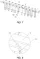
FIG. 7 is a schematic structural view of a tab holder provided inEmbodiment 2 of the present disclosure. -
FIG. 8 is a partial enlarged view at part C inFIG. 7 . -
FIG. 9 is a partial enlarged view of the connection between the connected tab provided by theEmbodiment 2 of the present disclosure after passing through the tab holder and connecting to the connector. -
FIG. 10 is a partial view of a first spacer provided inEmbodiment 2 of the present disclosure. - 1. side plate; 2. end plate; 21. exhaust hole; 3. cell; 31. tab; 4. heat insulation plate; 5. first spacer; 51. partition plates; 52. horizontal plates; 6. second spacer; 7. top plate; 8. connector; 9. tab holder; 91. wire harness area; 911. wire harness stopper; 912. wire harness fixing post; 92. tab separation area; 921. divider; 922. connection hole.
- In the description of the present disclosure, unless otherwise clearly specified and limited, the terms "connected", "linked" and "fixed" should be understood in a broad sense, for example, the above terms may refer to a fixed connection, a detachable connection, or integral formation; mechanical or electrical connection; direction connection or indirect connection through an intermediary; or the internal communication of two components or the interaction relationship between two components. Those of ordinary skill in the art can understand the specific meanings of the above terms in the present disclosure in specific situations.
- In the present disclosure, unless otherwise clearly specified and limited, a first feature being "on" or "below" a second feature may indicate direct contact between the first and second features, and may also indicate that the first and second features are not in direct contact but are in indirect contact through another feature between them. Moreover, the first feature being "above", "over" and "on" the second feature indicates that the first feature is directly above and obliquely above the second feature, or merely indicates that the first feature is at a level higher than the second feature. The first feature being "below", "beneath" and "under" the second feature indicates that the first feature is directly below and obliquely below the second feature, or simply means that the first feature is at a level lower than the second feature.
- In the description of the present disclosure, the orientation or positional relationship of the terms "upper", "lower", "left", "right" is interpreted based on the orientation or positional relationship shown in the accompanying drawings, and are only for the convenience of description and simplification of operation. It does not indicate or imply that the device or element referred to must have a specific orientation, be constructed and operate in a specific orientation, and therefore should not be construed as limitation to the present disclosure. In addition, the terms "first" and "second" are only used for discrimination in description, and have no special meaning.
- The present disclosure provides a busbar-less battery module and a battery pack. The battery pack includes a busbar-less battery module, the busbar-less battery module includes: a plurality of cells (3), tabs (31) are provided at both ends of each cell (3), and the interconnected cells (3) are directly connected through the tabs (31). An isolation component is provided between the adjacent cells (3).
- The disclosure will be described in detail below in conjunction with the accompanying drawings and embodiments.
- The
Embodiment 1 provides a battery pack, which may isolate adj acent tabs after thermal runaway occurs, thus preventing tabs undergoing thermal runaway from affecting adjacent tabs and causing thermal runaway to adjacent tabs, thereby preventing spread of heat at the tabs. - The battery pack includes a busbar-less battery module, as shown in
FIG. 1 and FIG. 2 . The busbar-less battery module includes an outer enclosing plate, a bottom plate, atop plate 7 and a plurality of cells3. Thetop plate 7 and the bottom plate are respectively arranged on the top and the bottom of the outer enclosing plate, and are respectively connected with the outer enclosing plate. The outer enclosing plate includes twoopposite side plates 1 and twoopposite end plates 2, and theend plates 2 are arranged between theside plates 1. - As shown in
FIG. 3 to FIG. 5 ,tabs 31 are provided at both ends of thecell 3, theinterconnected cells 3 are directly connected through thetabs 31, and thetabs 31 are connected in series or in parallel. Aheat insulation plate 4 is arranged between theadjacent cells 3. The first end of eachheat insulation plate 4 is located in the area enclosed by theconnected tabs 31 for theadjacent cell 3, and the distance between the second end of eachheat insulation plate 4 and theend plate 2 is smaller than the distance between thetab 31 and theend plate 2. - Since the
heat insulation plate 4 is arranged between theadjacent cells 3 and the battery module is not provided with the bus bar, the design without the bus bar prevents the bus bar from blocking the high-temperature fume. Therefore, thetabs 31 are directly connected, and the high-temperature fume may be discharged in time when thermal runaway occurs. The twoheat insulation plates 4 that are arranged at intervals and are not located in the area enclosed by the welded tabs may limit the weldedtabs 31 in a separate area. The separate area may isolate the weldedtab 31 fromother tabs 31 and slows down the heat spreading speed at the weldedtab 31. After the bus bar is eliminated, thetabs 31 are directly connected, for example, by welding, which helps to effectively discharge the high-temperature fume when thermal runaway occurs. - The busbar-less battery module includes an outer enclosing plate and a plurality of cells. The outer enclosing plate includes two opposite side plates and two opposite end plates, and the end plates are arranged between the side plates. The two ends of the cell are provided with tabs and the cells are directly connected through the tabs. A heat insulation plate is set between adjacent cells. The first end of each heat insulation plate is located in the area enclosed by the connected tabs for the adjacent cells. The distance between the second end of each heat insulation plate and the end plate is smaller than the distance between the tab and the end plate. Since there is a heat insulation plate between adjacent cells and the battery module is not provided with a bus bar, the design without the bus bar prevents the bus bar from blocking the high-temperature fume. Accordingly, because the tabs are directly connected, the high-temperature fume may be exhausted in time when thermal runaway occurs. The distance between the second end of each heat insulation plate and the end plate is smaller than the distance between the tab and the end plate, and the two longer heat insulation plates arranged at intervals may limit the welded tabs in a separation area (that is, two heat insulation plates arranged at intervals and not located in the area enclosed by the welded tabs may limit the tab to a separate area), such separate area may prevent adjacent tabs from contacting each other during operation and causing thermal runaway due to short circuit. Besides, the separate area may isolate the welded tab from other tabs, thereby slowing down the heat spreading speed at the welded tab. When the bus bar is omitted and the tabs are directly connected, it is possible for the high-temperature fume undergoing thermal runaway to be discharged effectively. The length of the heat insulation plate is longer than that of the heat insulation plate with bus bars, and the heat preservation effect is better.
- When the busbar-less battery module is large, the heat of a
single cell 3 spreads faster after thermal runaway occurs. In order to slowing down the spreading speed of heat, refer toFIG 2 . In this embodiment, the busbar-less battery module further includes a spacer, and the spacer is arranged between thecells 3 in order to dividemultiple cells 3 into multiple cell groups. Each cell group at least includes single body of twocells 3. It may be understood that the number ofcells 3 in each cell group can be uniformly or non-uniformly distributed, and the number ofcells 3 in each cell group is limited according to actual needs. It should be noted that the distance from the first end of the spacer to theend plate 2 is smaller than the distance from thetab 31 to theend plate 2, and the second end of the spacer is located in the area enclosed by theconnected tabs 31 for theadjacent cells 3. That is, the first end of the spacer may be arranged in contact with theend plate 2, thereby separatingmultiple cells 3 into independent cell groups, and the spacer cooperates with theheat insulation plate 4 to effectively reduce the heat spread speeding of thecell 3. - Optionally, the spacer includes a
first spacer 5 and asecond spacer 6. Thefirst spacer 5 includes a first frame and heat insulation layers arranged on both sides of the first frame. The first frame is provided with a first grooved channel along the length direction to allow the wires to pass through to facilitate wiring of the busbar-less battery module. Thesecond spacer 6 includes a second frame and heat insulation layers arranged on both sides of the second frame. Both thefirst spacer 5 and thesecond spacer 6 include heat insulation layers, and the heat insulation layers may slow down the heat spreading speed, so that thefirst spacer 5 and thesecond spacer 6 may effectively reduce the heat spreading speed after thermal runaway occurs to a cell group, thereby preventing thermal runaway from occurring to adjacent cell groups in a short period of time. - Since the
first spacer 5 is provided with a first grooved channel along the length direction to allow the wires to pass through, the thickness of thefirst spacer 5 is greater than the thickness of thesecond spacer 6. In order to connect thetabs 31 for thecell 3 at both ends of thefirst spacer 5, as shown inFIG. 3 to FIG. 5 , in this embodiment, thetabs 31 for thecell 3 on both sides of thefirst spacer 5 are welded through theconnector 8, that is, thetabs 31 for thecell 3 located on both sides of thefirst spacer 5 are welded to thesame connector 8 to realize the connection of thetabs 31, and theconnector 8 is a copper plate. In addition, in this embodiment, thetabs 31 for thecell 3 on both sides of thesecond spacer 6 and theheat insulation plate 4 are directly welded together. - In this embodiment, the bus bar is omitted, and the
tabs 31 are directly welded together, which helps to effectively discharge the high-temperature fume when thermal runaway occurs. In the meantime, there is no insulation support provided at both ends of thecell 3, the insulation support includes the tab holder, and the available space may allow accommodation of a longerheat insulation plate 4. The longer theheat insulation plate 4 is, the more heat may be suppressed. When theheat insulation plate 4 contacts theend plate 2, theheat insulation plate 4 on both sides of thetab 31 and theend plate 2 form a grid, and the grid helps to prevent the heat at thetab 31 from spreading to theadjacent tabs 31. Optionally, both the first frame and the second frame are made of metal. Both the first frame and the second frame are made of metal aluminum, and such design may improve the strength of thefirst spacer 5 and thesecond spacer 6. - Optionally, the first frame includes partition plates and horizontal plates. The partition plates are arranged at intervals, and the horizontal plates are arranged between the partition plates. Both ends of each horizontal plate are respectively connected to the partition plates, and the horizontal plates are arranged at intervals. The arrangement of the horizontal plates at intervals may form the first grooved channel, which facilitates wiring of the busbar-less battery module. In the meantime, the arrangement of the horizontal plates may also improve the strength of the
first spacer 5. - In order to be able to remove the fume from the busbar-less battery module, referring to
FIG. 1 and FIG. 2 , in this embodiment, a plurality of exhaust holes 21 are arranged on theend plate 2, and a plurality ofcells 3 and a plurality of exhaust holes 21 are arranged in one-to-one correspondence. Thecell 3 and theexhaust hole 21 are arranged in one-to-one correspondence, so it is possible to realize the directional exhaust function of thecell 3 undergoing thermal runaway, and help to slow down the thermal runaway of thecell 3, thereby improving the safety of battery pack. Optionally, theexhaust hole 21 is a waist-shaped hole, that is, an elongated hole. Since theexhaust hole 21 is long in length, such design will affect the overall strength of the busbar-less battery module. Therefore, in this embodiment, reinforcing ribs are disposed in the space enclosed by theexhaust hole 21. Exemplarily, a plurality of reinforcing ribs are arranged at intervals along the length direction of theexhaust hole 21. The plurality of reinforcing ribs are arranged in the space formed by theexhaust hole 21, and the reinforcing ribs are arranged along the length of theexhaust hole 21, such design makes it possible to effectively improve the strength of theend plate 2. - It should be noted that each
side plate 1 is provided with an output electrode, and thetab 31 of thecell 3 adjacent to theside plate 1 is welded to the output electrode through copper wires to ensure that the busbar-less battery module may be in normal use. - It should be noted that the heat insulation layer and the
heat insulation plate 4 may be heat-insulating ceramic material layers, aluminum oxide or glass fiber. - The thickness of the cell is often limited due to cell expansion, and such limitation leads to a significant restriction on the size of the bus bar after the cells are grouped together. Under the conditions that high-rate charging and discharging is required, considering various factors such as the current carrying capability, the constraints on the size of the bus bar, and the size requirements of the welding process, bus bar is no longer suitable to be adopted for realization of series-parallel connection. In light of the foregoing, the present embodiment provides a battery module. The battery module is not provided with a bus bar, so the tabs of the cell are directly fixed and connected together. By setting the tab separation area, it is possible to prevent the tabs on both sides of the tab separation area from contacting each other and causing short circuit. In this way, the reliability of the module may be ensured without busbars.
- As shown in
FIG. 6 , the busbar-less battery module includes a plurality ofcells 3, a tab holder 9, a spacer and an outer enclosing plate. The outer enclosing plate has a cavity. The outer enclosing plate includes atop plate 7, a bottom plate, twoside plates 1 and twoend plates 2. The twoside plates 1 are arranged opposite to each other. Both ends of eachend plate 2 are respectively connected with theside plate 1, and the twoend plates 2 are opposite to each other and arranged at intervals. Thetop plate 7 is set on the top of theend plate 2 and theside plate 1, the bottom plate is set on the bottom of theend plate 2 and theside plate 1. Thetop plate 7, the bottom plate, the twoside plates 1 and the twoend plates 2 are connected to form a cavity for accommodating thecell 3. Thecell 3, the tab holder 9 and spacer are placed in the cavity enclosed by the outer enclosing plate.Multiple cells 3 are connected in series or in parallel throughtabs 31, and the tab holder 9 is arranged at one end of thecell 3. - As shown in
FIG. 7 , at least one end of the lug holder 9 is connected with an output electrode, and the tab holder 9 includes awire harness area 91 and atab separation area 92 connected to thewire harness area 91. Thetab separation area 92 is provided with a plurality ofdividers 921, and the plurality ofdividers 921 are arranged at intervals to form connection holes 922. Eachconnection hole 922 is pierced with atab 31, and thetabs 31 pierced in thesame connection hole 922 are directly fixed and connected to each other through bending and stacking. Thewire harness area 91 is provided with a second grooved channel. - In the battery module provided in this embodiment, the
tabs 31 are directly fixed and connected to each other through bending and stacking. In the design without the bus bar, thecell 3 and thecell 3 are directly connected. In this way, the process may be simplified, and the cost may be effectively reduced. In the meantime, the design of omitting the bus bar makes it possible to provide sufficient accommodating space for other components. Moreover, the design without bus bar prevents the bus bar from blocking the high-temperature fume, so that the high-temperature fume may be exhausted in time when thermal runaway occurs. Thetab separation area 92 of the tab holder 9 may isolate thetabs 31 from each other to prevent short circuit due to contact of thetabs 31 during the working process of the battery module. The second grooved channel may integrate low-voltage acquisition lines to ensure the reliability of the battery module. - Optionally, referring to
FIG. 8 , in this embodiment, thewire harness area 91 is provided with a plurality ofwire harness stoppers 911 and a plurality of wireharness fixing posts 912, and a wireharness fixing post 912 is arranged above each connectinghole 922. Thewire harness stopper 911 and the wireharness fixing post 912 cooperate with each other to fix the wire harness, so that the low-voltage acquisition lines are neatly laid in thewire harness area 91 of the tab holder 9, so that the space at the front end of the tab holder 9 is reasonably utilized to prevent the low-voltage lines from becoming a mess. - When the battery module is large, the heat of a
single cell 3 spreads faster after thermal runaway occurs. In order to slowing down the spreading speed of heat, the battery module in the present embodiment further includes a spacer, and the spacer is arranged between thecells 3 in order to dividemultiple cells 3 into multiple cell groups. Each cell group at least includes twocells 3. When thecell 3 in one of the cell groups undergoes thermal runaway, due to the existence of the spacer, it is possible to prevent the heat generated by thecell 3 undergoing thermal runaway from spreading to the cell group not affected by thermal runaway. It may be understood that the number of wires in each cell group can be uniformly or non-uniformly distributed, and the number ofcells 3 in each cell group is limited according to actual needs. - Optionally, as shown in
FIG. 6 , the spacer includes afirst spacer 5 and a second spacer. Thefirst spacer 5 includes a first frame and heat insulation layers arranged on both sides of the first frame. The first frame is provided with a first grooved channel along the length direction to allow the wires to pass through to facilitate wiring of the battery module. The second spacer includes a second frame and heat insulation layers disposed on both sides of the second frame. Both thefirst spacer 5 and the second spacer include heat insulation layers, and the heat insulation layers may slow down the heat spreading speed, so that thefirst spacer 5 and the second spacer may effectively reduce the heat spreading speed after thermal runaway occurs to one cell. In this way, it is possible to prevent thermal runaway from occurring to adjacent cells in a short period of time. Thefirst spacer 5 is located in the middle of the battery module, and the second spacer is located on both sides of thefirst spacer 5. The number of thefirst spacer 5 is one, and the number of the second spacer is at least two. - Since the
first spacer 5 is provided with the first grooved channel along the length direction to allow the wires to pass through, the thickness of thefirst spacer 5 is greater than that of the second spacer. In order to connect thetabs 31 for thecell 3 at both ends of thefirst spacer 5, in this embodiment, as shown inFIG. 9 , thetabs 31 for thecell 3 on both sides of thefirst spacer 5 are welded together through theconnector 8, that is, thetabs 31 for thecell 3 located on both sides of thefirst spacer 5 are welded to thesame connector 8 to realize the connection of thetabs 31. In an embodiment, theconnector 8 is a copper plate. In this embodiment, thetabs 31 for thecells 3 of the second spacer are directly welded together. In this embodiment, the bus bar is omitted, and thetab 31 is directly welded, which helps to effectively discharge the high-temperature fume when thermal runaway occurs. Optionally, both the first frame and the second frame are made of metal. Both the first frame and the second frame are made of metal aluminum, and such design may improve the strength of thefirst spacer 5 and the second spacer. - Optionally, as shown in
FIG. 10 , the first frame includespartition plates 51 andhorizontal plates 52, thepartition plates 51 are arranged at intervals, and thehorizontal plates 52 are arranged between thepartition plates 51. Both ends of eachhorizontal plate 52 are respectively connected to thepartition plates 51, and thehorizontal plates 52 are arranged at intervals. Thehorizontal plates 52 arranged at intervals may form a first grooved channel to facilitate the wiring of the battery module. Meanwhile, the arrangement of thehorizontal plates 52 may also improve the strength of thefirst spacer 5. - In order to remove heat from the battery module, in this embodiment, as shown in
FIG. 6 , multiple exhaust holes 21 are provided on theend plate 2, andmultiple cells 3 and multiple exhaust holes 21 are arranged in one-to-one correspondence. Thecell 3 and theexhaust hole 21 are set in one-to-one correspondence, which may realize the directional exhaust function of thecell 3 undergoing thermal runaway, which makes it possible to slow down thermal runaway of thecell 3 and improve the safety of the battery pack. Optionally, theexhaust hole 21 is a waist-shaped hole, that is, an elongated hole. Since theexhaust hole 21 is long, such design will affect the overall strength of the battery module. Therefore, in this embodiment, the space enclosed by theexhaust hole 21 is provided with reinforcing ribs. Exemplarily, a plurality of reinforcing ribs are arranged at intervals along the length direction of theexhaust hole 21. A plurality of reinforcing ribs are arranged in the space formed by theexhaust hole 21, and the reinforcing ribs are arranged along the length of theexhaust hole 21, thereby effectively improving the strength of theend plate 2. - It should be noted that each
side plate 1 is provided with an output electrode, and thetabs 31 for thecell 3 adjacent to theside plate 1 are welded to the output electrode through copper wires to ensure that the battery module may be in normal use. -
Embodiment 2 of the present disclosure further provides a battery pack, which includes the busbar-less battery module described inEmbodiment 2.
Claims (20)
- A busbar-less battery module, comprising:
a plurality of cells (3), wherein tabs (31) are provided at both ends of each of the cells (3), and the interconnected cells (3) are directly connected through the tabs (31), and an isolation component is provided between the adjacent cells (3). - The busbar-less battery module according to claim 1, wherein the isolation component is a heat insulation plate (4), and the busbar-less battery module further comprises:an outer enclosing plate, which comprises two opposite side plates (1) and two opposite end plates (2), and the end plates (2) are arranged between the side plates (1);wherein the heat insulation plate (4) is arranged between the adjacent cells (3), a first end of each of the heat insulation plates (4) is located in an area enclosed by the connected tabs (31) for the adjacent cells (3), and a distance between a second end of each of the heat insulation plates (4) and the end plate (2) is smaller than a distance between the tab (31) and the end plate (2).
- The busbar-less battery module according to claim 2, further comprising a spacer, wherein the spacer is arranged between the cells (3) to divide the plurality of cells (3) into a plurality of cell groups, each of the cell groups at least comprises two of the cells (3), a distance from a first end of the spacer to the end plate (2) is smaller than a distance from the tab (31) to the end plate (2), and second ends of the spacer are in the area enclosed by the connected tabs (31) for the adjacent cells (3).
- The busbar-less battery module according to claim 3, wherein the spacer comprises a first spacer (5) and a second spacer (6), the first spacer (5) comprises a first frame and heat insulation layers on both sides of the first frame, the first frame is provided with a first grooved channel along a length direction to allow wires to pass through, and the second spacer (6) comprises a second frame and heat insulation layers disposed on both sides of the second frame.
- The busbar-less battery module according to claim 4, wherein the tabs (31) for the cells (3) on both sides of the first spacer (5) are welded through connectors (8); the tabs (31) for the cells (3) on both sides of the second spacer (6) and the heat insulation plate (4) are welded together.
- The busbar-less battery module according to claim 4, wherein both the first frame and the second frame are made of metal.
- The busbar-less battery module according to claim 4, wherein the first frame comprises partition plates (51) and horizontal plates (52), the partition plates (51) are arranged at intervals, the horizontal plates (52) are arranged between the partition plates (51), and two ends of each of the horizontal plates (52) are respectively connected to the partition plates (51), and the horizontal plates (52) are arranged at intervals.
- The busbar-less battery module according to claim 2, wherein the end plate (2) is provided with a plurality of exhaust holes (21), and the plurality of cells (3) and the plurality of exhaust holes (21) are provided in one-to-one correspondence.
- The busbar-less battery module according to claim 8, wherein reinforcing ribs are arranged in a space enclosed by the exhaust hole (21), and the reinforcing ribs are arranged at intervals along a length direction of the exhaust hole (21).
- The busbar-less battery module according to any one of claims 2-8, wherein no insulation support is provided at the both ends of the cell (3).
- The busbar-less battery module according to claim 1, wherein the isolation component is a tab holder (9);the plurality of cells (3) are connected in series or in parallel through the tabs (31);the tab holder (9) is arranged at one end of the cell (3), at least one end of the tab holder (9) is connected to an output electrode, the tab holder (9) comprises a wire harness area (91) and a tab separation area (92) connected to the wire harness area (91), the tab separation area (92) is provided with a plurality of dividers (921), and the plurality of dividers (921) are arranged at intervals to form connection holes (922), each of the connection holes (922) is pierced with the tabs (31), and the tabs (31) pierced through the same connection hole (922) are directly fixed and connected to each other through bending and stacking.
- The busbar-less battery module according to claim 11, wherein the wire harness area (91) is provided with a plurality of wire harness stoppers (911) and a plurality of wire harness fixing posts (912), and one of the wire harness fixing posts (912) is provided above each of the connection holes (922).
- The busbar-less battery module according to claim 11, further comprising a spacer, wherein the spacer is arranged between the cells (3) to divide the plurality of the cells (3) into a plurality of cell groups, and each of the cell groups at least comprises two of the cells (3).
- The busbar-less battery module according to claim 13, wherein the spacer comprises a first spacer (5) and a second spacer (6), the first spacer (5) is located in the middle of the battery module, and both sides of the first spacer (5) are respectively provided with the second spacer (6), the first spacer (5) comprises a first frame and heat insulation layers arranged on both sides of the first frame, and the first frame is provided with a first grooved channel along a length direction to allow wires to pass through, the second spacer (6) comprises a second frame and heat insulation layers arranged on both sides of the second frame.
- The busbar-less battery module according to claim 14, wherein the tabs (31) for the cells (31) arranged on the both sides of the first spacer (5) are welded by connectors (8); the tabs (31) for the cells (3) on both sides of the second spacer (6) are welded to each other.
- The busbar-less battery module according to claim 14, wherein both the first frame and the second frame are made of metal.
- The busbar-less battery module according to claim 14, wherein the first frame comprises partition plates (51) and horizontal plates (52), the partition plates (51) are arranged at intervals, and the horizontal plates (552) are arranged between the partition plates (51), both ends of each of the horizontal plates (52) are respectively connected to the partition plates (51), and the horizontal plates (52) are arranged at intervals to form the first grooved channel.
- The busbar-less battery module according to claim 11, further comprising an outer enclosing plate, wherein the outer enclosing plate comprises a top plate (7), a bottom plate, two opposite side plates (1) and two opposite end plates (2), both ends of each of the end plates (2) are respectively connected to the two side plates (1), the top plate (7), the bottom plate, the two end plates (2) and the two side plates (1) are connected to form a cavity for accommodating the cell (3), a plurality of exhaust holes (21) are arranged on the end plates (2), and the plurality of cells (3) and the plurality of exhaust holes (21) are arranged in one-to-one correspondence.
- The busbar-less battery module according to claim 18, wherein reinforcing ribs are arranged in a space enclosed by the exhaust hole (21).
- A battery pack, comprising the busbar-less battery module according to any one of claims 1-19.
Applications Claiming Priority (1)
| Application Number | Priority Date | Filing Date | Title |
|---|---|---|---|
| PCT/CN2021/143665 WO2023123350A1 (en) | 2021-12-31 | 2021-12-31 | Battery module without busbar, and battery pack |
Publications (2)
| Publication Number | Publication Date |
|---|---|
| EP4459786A1 true EP4459786A1 (en) | 2024-11-06 |
| EP4459786A4 EP4459786A4 (en) | 2025-12-17 |
Family
ID=86997189
Family Applications (1)
| Application Number | Title | Priority Date | Filing Date |
|---|---|---|---|
| EP21969701.8A Pending EP4459786A4 (en) | 2021-12-31 | 2021-12-31 | BATTERY MODULE EQUIPPED WITH AN OMNIBUS BAR AND BATTERY BLOCK |
Country Status (5)
| Country | Link |
|---|---|
| US (1) | US20240145856A1 (en) |
| EP (1) | EP4459786A4 (en) |
| JP (1) | JP7752706B2 (en) |
| CN (1) | CN221080294U (en) |
| WO (1) | WO2023123350A1 (en) |
Families Citing this family (6)
| Publication number | Priority date | Publication date | Assignee | Title |
|---|---|---|---|---|
| US20240079740A1 (en) * | 2022-09-02 | 2024-03-07 | Ford Global Technologies, Llc | Method of assembling traction battery pack and traction battery pack assembly |
| CN117317510B (en) * | 2023-11-29 | 2024-03-19 | 杭州卡涞复合材料科技有限公司 | Battery module and energy storage box |
| KR20260045352A (en) * | 2024-09-27 | 2026-04-03 | 주식회사 엘지에너지솔루션 | Secondary battery including cell lead having gap measuring hole and welding method for cell lead |
| DE102024128631A1 (en) | 2024-10-02 | 2026-04-02 | Audi Aktiengesellschaft | Prismatic battery cell and battery cell assembly |
| DE102024128632A1 (en) | 2024-10-02 | 2026-04-02 | Audi Aktiengesellschaft | Prismatic battery cell and battery cell assembly |
| CN121642388A (en) * | 2026-02-04 | 2026-03-10 | 中创新航科技集团股份有限公司 | Battery modules, battery packs and electrical devices |
Family Cites Families (9)
| Publication number | Priority date | Publication date | Assignee | Title |
|---|---|---|---|---|
| JP2008166191A (en) * | 2006-12-28 | 2008-07-17 | Sanyo Electric Co Ltd | Battery pack |
| KR101140449B1 (en) * | 2007-09-19 | 2012-04-30 | 에스케이이노베이션 주식회사 | Module pack For Secondary Battery |
| JP2012124319A (en) * | 2010-12-08 | 2012-06-28 | Jm Energy Corp | Power storage device |
| JP5765769B2 (en) * | 2011-03-31 | 2015-08-19 | Necエナジーデバイス株式会社 | Battery pack |
| KR102308635B1 (en) * | 2015-04-17 | 2021-10-05 | 삼성에스디아이 주식회사 | Battery module |
| JP7075580B2 (en) * | 2018-02-23 | 2022-05-26 | トヨタ自動車株式会社 | Laminated battery module |
| KR102382382B1 (en) * | 2018-07-03 | 2022-04-01 | 주식회사 엘지에너지솔루션 | Battery Module Having Heat-Shrinkable Tube |
| CN210379226U (en) * | 2019-07-05 | 2020-04-21 | 恒大新能源科技集团有限公司 | A busbarless battery module structure |
| CN113140852A (en) * | 2021-04-22 | 2021-07-20 | 远景动力技术(江苏)有限公司 | Battery pack |
-
2021
- 2021-12-31 JP JP2023573668A patent/JP7752706B2/en active Active
- 2021-12-31 EP EP21969701.8A patent/EP4459786A4/en active Pending
- 2021-12-31 CN CN202190000996.XU patent/CN221080294U/en active Active
- 2021-12-31 US US18/567,773 patent/US20240145856A1/en active Pending
- 2021-12-31 WO PCT/CN2021/143665 patent/WO2023123350A1/en not_active Ceased
Also Published As
| Publication number | Publication date |
|---|---|
| WO2023123350A1 (en) | 2023-07-06 |
| CN221080294U (en) | 2024-06-04 |
| JP2024520579A (en) | 2024-05-24 |
| US20240145856A1 (en) | 2024-05-02 |
| JP7752706B2 (en) | 2025-10-10 |
| EP4459786A4 (en) | 2025-12-17 |
Similar Documents
| Publication | Publication Date | Title |
|---|---|---|
| EP4459786A1 (en) | Battery module without busbar, and battery pack | |
| EP3809516B1 (en) | Battery module and insulating plate | |
| KR102885098B1 (en) | A battery module with multiple parallel battery cells | |
| JP2022533789A (en) | Battery modules, power battery packs and vehicles | |
| WO2014054888A2 (en) | Battery pack | |
| CN116349072A (en) | Battery module, battery, consumer, method and device for producing a battery | |
| CN117613498A (en) | Battery, electric device, method and equipment for preparing battery | |
| JP2016512376A (en) | Rechargeable battery including battery cell separator | |
| WO2024055508A1 (en) | Battery cell module and battery pack | |
| WO2012148211A2 (en) | Battery module | |
| CN216698629U (en) | Battery module and battery pack | |
| CN209641723U (en) | Transfer bus, battery modules and battery pack | |
| CN215731966U (en) | Battery module and battery pack | |
| CN222851621U (en) | Battery device and electricity utilization device | |
| EP4459742A1 (en) | Battery module and battery pack | |
| KR102848799B1 (en) | Air-Cooling battery module with individual battery cell cooling structures | |
| EP4181285A1 (en) | Battery, electrical device, and battery production method and device | |
| CN210427758U (en) | BMS battery management system | |
| CN221162259U (en) | Dual-system battery module, battery system and electric automobile | |
| CN218783188U (en) | CCS components, battery modules and electrical equipment | |
| CN217848255U (en) | Battery pack with insulating layer and battery pack | |
| CN214957173U (en) | Battery packs and electrical devices | |
| CN213601900U (en) | Single-module integrated lithium battery pack | |
| CN222995629U (en) | Battery pack and electricity utilization device | |
| CN217114725U (en) | Non-bus battery module and battery pack |
Legal Events
| Date | Code | Title | Description |
|---|---|---|---|
| STAA | Information on the status of an ep patent application or granted ep patent |
Free format text: STATUS: THE INTERNATIONAL PUBLICATION HAS BEEN MADE |
|
| PUAI | Public reference made under article 153(3) epc to a published international application that has entered the european phase |
Free format text: ORIGINAL CODE: 0009012 |
|
| STAA | Information on the status of an ep patent application or granted ep patent |
Free format text: STATUS: REQUEST FOR EXAMINATION WAS MADE |
|
| 17P | Request for examination filed |
Effective date: 20231219 |
|
| AK | Designated contracting states |
Kind code of ref document: A1 Designated state(s): AL AT BE BG CH CY CZ DE DK EE ES FI FR GB GR HR HU IE IS IT LI LT LU LV MC MK MT NL NO PL PT RO RS SE SI SK SM TR |
|
| DAV | Request for validation of the european patent (deleted) | ||
| DAX | Request for extension of the european patent (deleted) | ||
| RIC1 | Information provided on ipc code assigned before grant |
Ipc: H01M 50/593 20210101AFI20250825BHEP Ipc: H01M 50/296 20210101ALI20250825BHEP Ipc: H01M 50/209 20210101ALI20250825BHEP Ipc: H01M 50/289 20210101ALI20250825BHEP Ipc: H01M 50/548 20210101ALI20250825BHEP Ipc: H01M 10/658 20140101ALI20250825BHEP Ipc: H01M 50/211 20210101ALI20250825BHEP Ipc: H01M 50/30 20210101ALI20250825BHEP Ipc: H01M 50/502 20210101ALI20250825BHEP Ipc: H01M 50/516 20210101ALI20250825BHEP |
|
| A4 | Supplementary search report drawn up and despatched |
Effective date: 20251119 |
|
| RIC1 | Information provided on ipc code assigned before grant |
Ipc: H01M 50/593 20210101AFI20251113BHEP Ipc: H01M 50/296 20210101ALI20251113BHEP Ipc: H01M 50/209 20210101ALI20251113BHEP Ipc: H01M 50/289 20210101ALI20251113BHEP Ipc: H01M 50/548 20210101ALI20251113BHEP Ipc: H01M 10/658 20140101ALI20251113BHEP Ipc: H01M 50/211 20210101ALI20251113BHEP Ipc: H01M 50/30 20210101ALI20251113BHEP Ipc: H01M 50/502 20210101ALI20251113BHEP Ipc: H01M 50/516 20210101ALI20251113BHEP |