EP4459785A1 - Power storage device - Google Patents
Power storage device Download PDFInfo
- Publication number
- EP4459785A1 EP4459785A1 EP22915944.7A EP22915944A EP4459785A1 EP 4459785 A1 EP4459785 A1 EP 4459785A1 EP 22915944 A EP22915944 A EP 22915944A EP 4459785 A1 EP4459785 A1 EP 4459785A1
- Authority
- EP
- European Patent Office
- Prior art keywords
- connection portion
- bridge
- storage device
- power storage
- axial direction
- Prior art date
- Legal status (The legal status is an assumption and is not a legal conclusion. Google has not performed a legal analysis and makes no representation as to the accuracy of the status listed.)
- Granted
Links
Images




Classifications
-
- H—ELECTRICITY
- H01—ELECTRIC ELEMENTS
- H01M—PROCESSES OR MEANS, e.g. BATTERIES, FOR THE DIRECT CONVERSION OF CHEMICAL ENERGY INTO ELECTRICAL ENERGY
- H01M10/00—Secondary cells; Manufacture thereof
- H01M10/05—Accumulators with non-aqueous electrolyte
- H01M10/058—Construction or manufacture
- H01M10/0587—Construction or manufacture of accumulators having only wound construction elements, i.e. wound positive electrodes, wound negative electrodes and wound separators
-
- H—ELECTRICITY
- H01—ELECTRIC ELEMENTS
- H01G—CAPACITORS; CAPACITORS, RECTIFIERS, DETECTORS, SWITCHING DEVICES, LIGHT-SENSITIVE OR TEMPERATURE-SENSITIVE DEVICES OF THE ELECTROLYTIC TYPE
- H01G11/00—Hybrid capacitors, i.e. capacitors having different positive and negative electrodes; Electric double-layer [EDL] capacitors; Processes for the manufacture thereof or of parts thereof
- H01G11/78—Cases; Housings; Encapsulations; Mountings
-
- H—ELECTRICITY
- H01—ELECTRIC ELEMENTS
- H01G—CAPACITORS; CAPACITORS, RECTIFIERS, DETECTORS, SWITCHING DEVICES, LIGHT-SENSITIVE OR TEMPERATURE-SENSITIVE DEVICES OF THE ELECTROLYTIC TYPE
- H01G11/00—Hybrid capacitors, i.e. capacitors having different positive and negative electrodes; Electric double-layer [EDL] capacitors; Processes for the manufacture thereof or of parts thereof
- H01G11/14—Arrangements or processes for adjusting or protecting hybrid or EDL capacitors
-
- H—ELECTRICITY
- H01—ELECTRIC ELEMENTS
- H01G—CAPACITORS; CAPACITORS, RECTIFIERS, DETECTORS, SWITCHING DEVICES, LIGHT-SENSITIVE OR TEMPERATURE-SENSITIVE DEVICES OF THE ELECTROLYTIC TYPE
- H01G11/00—Hybrid capacitors, i.e. capacitors having different positive and negative electrodes; Electric double-layer [EDL] capacitors; Processes for the manufacture thereof or of parts thereof
- H01G11/14—Arrangements or processes for adjusting or protecting hybrid or EDL capacitors
- H01G11/16—Arrangements or processes for adjusting or protecting hybrid or EDL capacitors against electric overloads, e.g. including fuses
-
- H—ELECTRICITY
- H01—ELECTRIC ELEMENTS
- H01G—CAPACITORS; CAPACITORS, RECTIFIERS, DETECTORS, SWITCHING DEVICES, LIGHT-SENSITIVE OR TEMPERATURE-SENSITIVE DEVICES OF THE ELECTROLYTIC TYPE
- H01G11/00—Hybrid capacitors, i.e. capacitors having different positive and negative electrodes; Electric double-layer [EDL] capacitors; Processes for the manufacture thereof or of parts thereof
- H01G11/74—Terminals, e.g. extensions of current collectors
-
- H—ELECTRICITY
- H01—ELECTRIC ELEMENTS
- H01M—PROCESSES OR MEANS, e.g. BATTERIES, FOR THE DIRECT CONVERSION OF CHEMICAL ENERGY INTO ELECTRICAL ENERGY
- H01M10/00—Secondary cells; Manufacture thereof
- H01M10/04—Construction or manufacture in general
- H01M10/0422—Cells or battery with cylindrical casing
-
- H—ELECTRICITY
- H01—ELECTRIC ELEMENTS
- H01M—PROCESSES OR MEANS, e.g. BATTERIES, FOR THE DIRECT CONVERSION OF CHEMICAL ENERGY INTO ELECTRICAL ENERGY
- H01M10/00—Secondary cells; Manufacture thereof
- H01M10/04—Construction or manufacture in general
- H01M10/0431—Cells with wound or folded electrodes
-
- H—ELECTRICITY
- H01—ELECTRIC ELEMENTS
- H01M—PROCESSES OR MEANS, e.g. BATTERIES, FOR THE DIRECT CONVERSION OF CHEMICAL ENERGY INTO ELECTRICAL ENERGY
- H01M50/00—Constructional details or processes of manufacture of the non-active parts of electrochemical cells other than fuel cells, e.g. hybrid cells
- H01M50/10—Primary casings; Jackets or wrappings
- H01M50/102—Primary casings; Jackets or wrappings characterised by their shape or physical structure
- H01M50/107—Primary casings; Jackets or wrappings characterised by their shape or physical structure having curved cross-section, e.g. round or elliptic
-
- H—ELECTRICITY
- H01—ELECTRIC ELEMENTS
- H01M—PROCESSES OR MEANS, e.g. BATTERIES, FOR THE DIRECT CONVERSION OF CHEMICAL ENERGY INTO ELECTRICAL ENERGY
- H01M50/00—Constructional details or processes of manufacture of the non-active parts of electrochemical cells other than fuel cells, e.g. hybrid cells
- H01M50/10—Primary casings; Jackets or wrappings
- H01M50/147—Lids or covers
- H01M50/148—Lids or covers characterised by their shape
- H01M50/152—Lids or covers characterised by their shape for cells having curved cross-section, e.g. round or elliptic
-
- H—ELECTRICITY
- H01—ELECTRIC ELEMENTS
- H01M—PROCESSES OR MEANS, e.g. BATTERIES, FOR THE DIRECT CONVERSION OF CHEMICAL ENERGY INTO ELECTRICAL ENERGY
- H01M50/00—Constructional details or processes of manufacture of the non-active parts of electrochemical cells other than fuel cells, e.g. hybrid cells
- H01M50/50—Current conducting connections for cells or batteries
- H01M50/543—Terminals
- H01M50/545—Terminals formed by the casing of the cells
-
- H—ELECTRICITY
- H01—ELECTRIC ELEMENTS
- H01M—PROCESSES OR MEANS, e.g. BATTERIES, FOR THE DIRECT CONVERSION OF CHEMICAL ENERGY INTO ELECTRICAL ENERGY
- H01M50/00—Constructional details or processes of manufacture of the non-active parts of electrochemical cells other than fuel cells, e.g. hybrid cells
- H01M50/50—Current conducting connections for cells or batteries
- H01M50/543—Terminals
- H01M50/547—Terminals characterised by the disposition of the terminals on the cells
-
- H—ELECTRICITY
- H01—ELECTRIC ELEMENTS
- H01M—PROCESSES OR MEANS, e.g. BATTERIES, FOR THE DIRECT CONVERSION OF CHEMICAL ENERGY INTO ELECTRICAL ENERGY
- H01M50/00—Constructional details or processes of manufacture of the non-active parts of electrochemical cells other than fuel cells, e.g. hybrid cells
- H01M50/50—Current conducting connections for cells or batteries
- H01M50/543—Terminals
- H01M50/547—Terminals characterised by the disposition of the terminals on the cells
- H01M50/55—Terminals characterised by the disposition of the terminals on the cells on the same side of the cell
-
- H—ELECTRICITY
- H01—ELECTRIC ELEMENTS
- H01M—PROCESSES OR MEANS, e.g. BATTERIES, FOR THE DIRECT CONVERSION OF CHEMICAL ENERGY INTO ELECTRICAL ENERGY
- H01M50/00—Constructional details or processes of manufacture of the non-active parts of electrochemical cells other than fuel cells, e.g. hybrid cells
- H01M50/50—Current conducting connections for cells or batteries
- H01M50/543—Terminals
- H01M50/552—Terminals characterised by their shape
- H01M50/559—Terminals adapted for cells having curved cross-section, e.g. round, elliptic or button cells
-
- H—ELECTRICITY
- H01—ELECTRIC ELEMENTS
- H01M—PROCESSES OR MEANS, e.g. BATTERIES, FOR THE DIRECT CONVERSION OF CHEMICAL ENERGY INTO ELECTRICAL ENERGY
- H01M50/00—Constructional details or processes of manufacture of the non-active parts of electrochemical cells other than fuel cells, e.g. hybrid cells
- H01M50/50—Current conducting connections for cells or batteries
- H01M50/543—Terminals
- H01M50/552—Terminals characterised by their shape
- H01M50/559—Terminals adapted for cells having curved cross-section, e.g. round, elliptic or button cells
- H01M50/56—Cup shaped terminals
-
- H—ELECTRICITY
- H01—ELECTRIC ELEMENTS
- H01M—PROCESSES OR MEANS, e.g. BATTERIES, FOR THE DIRECT CONVERSION OF CHEMICAL ENERGY INTO ELECTRICAL ENERGY
- H01M50/00—Constructional details or processes of manufacture of the non-active parts of electrochemical cells other than fuel cells, e.g. hybrid cells
- H01M50/50—Current conducting connections for cells or batteries
- H01M50/572—Means for preventing undesired use or discharge
- H01M50/574—Devices or arrangements for the interruption of current
- H01M50/578—Devices or arrangements for the interruption of current in response to pressure
-
- H—ELECTRICITY
- H01—ELECTRIC ELEMENTS
- H01M—PROCESSES OR MEANS, e.g. BATTERIES, FOR THE DIRECT CONVERSION OF CHEMICAL ENERGY INTO ELECTRICAL ENERGY
- H01M50/00—Constructional details or processes of manufacture of the non-active parts of electrochemical cells other than fuel cells, e.g. hybrid cells
- H01M50/50—Current conducting connections for cells or batteries
- H01M50/572—Means for preventing undesired use or discharge
- H01M50/574—Devices or arrangements for the interruption of current
- H01M50/583—Devices or arrangements for the interruption of current in response to current, e.g. fuses
-
- H—ELECTRICITY
- H01—ELECTRIC ELEMENTS
- H01M—PROCESSES OR MEANS, e.g. BATTERIES, FOR THE DIRECT CONVERSION OF CHEMICAL ENERGY INTO ELECTRICAL ENERGY
- H01M50/00—Constructional details or processes of manufacture of the non-active parts of electrochemical cells other than fuel cells, e.g. hybrid cells
- H01M50/50—Current conducting connections for cells or batteries
- H01M50/572—Means for preventing undesired use or discharge
- H01M50/584—Means for preventing undesired use or discharge for preventing incorrect connections inside or outside the batteries
- H01M50/588—Means for preventing undesired use or discharge for preventing incorrect connections inside or outside the batteries outside the batteries, e.g. incorrect connections of terminals or busbars
-
- H—ELECTRICITY
- H01—ELECTRIC ELEMENTS
- H01M—PROCESSES OR MEANS, e.g. BATTERIES, FOR THE DIRECT CONVERSION OF CHEMICAL ENERGY INTO ELECTRICAL ENERGY
- H01M50/00—Constructional details or processes of manufacture of the non-active parts of electrochemical cells other than fuel cells, e.g. hybrid cells
- H01M50/50—Current conducting connections for cells or batteries
- H01M50/572—Means for preventing undesired use or discharge
- H01M50/584—Means for preventing undesired use or discharge for preventing incorrect connections inside or outside the batteries
- H01M50/59—Means for preventing undesired use or discharge for preventing incorrect connections inside or outside the batteries characterised by the protection means
- H01M50/593—Spacers; Insulating plates
-
- H—ELECTRICITY
- H01—ELECTRIC ELEMENTS
- H01M—PROCESSES OR MEANS, e.g. BATTERIES, FOR THE DIRECT CONVERSION OF CHEMICAL ENERGY INTO ELECTRICAL ENERGY
- H01M2200/00—Safety devices for primary or secondary batteries
- H01M2200/10—Temperature sensitive devices
- H01M2200/103—Fuse
-
- H—ELECTRICITY
- H01—ELECTRIC ELEMENTS
- H01M—PROCESSES OR MEANS, e.g. BATTERIES, FOR THE DIRECT CONVERSION OF CHEMICAL ENERGY INTO ELECTRICAL ENERGY
- H01M2220/00—Batteries for particular applications
- H01M2220/20—Batteries in motive systems, e.g. vehicle, ship, plane
-
- Y—GENERAL TAGGING OF NEW TECHNOLOGICAL DEVELOPMENTS; GENERAL TAGGING OF CROSS-SECTIONAL TECHNOLOGIES SPANNING OVER SEVERAL SECTIONS OF THE IPC; TECHNICAL SUBJECTS COVERED BY FORMER USPC CROSS-REFERENCE ART COLLECTIONS [XRACs] AND DIGESTS
- Y02—TECHNOLOGIES OR APPLICATIONS FOR MITIGATION OR ADAPTATION AGAINST CLIMATE CHANGE
- Y02E—REDUCTION OF GREENHOUSE GAS [GHG] EMISSIONS, RELATED TO ENERGY GENERATION, TRANSMISSION OR DISTRIBUTION
- Y02E60/00—Enabling technologies; Technologies with a potential or indirect contribution to GHG emissions mitigation
- Y02E60/10—Energy storage using batteries
Definitions
- the present disclosure relates to a power storage device having a current interrupting function.
- a mechanism for releasing gas is provided in an individual battery, but it is preferable to cut off a current in the battery when an abnormality occurs. Therefore, it has been proposed to provide a mechanism for cutting off a current when an abnormality occurs in a battery (hereinafter, a current interruption device (CID)).
- a current interruption device CID
- Patent Literature 1 a pair of holding plates that adhere to each other is provided on an exterior component of a battery, and a fragile element forming a conductive path is connected between the two holding plates. Then, the element is broken when the exterior component expands, thereby cutting off a current.
- Patent Literature 1 JP 2001-196049 A
- Patent Literature 1 the holding plates and the element are specially provided on the exterior component of the battery. Therefore, there is a problem that the number of components increases, which increases the cost, and when batteries are stacked, the external sizes of the batteries increases.
- an electric circuit interruption mechanism that monitors a battery voltage and interrupts a current when an abnormality is detected from the detected value of the battery voltage may be provided, but there are many cases where a current cannot be sufficiently interrupted in response to an abnormality of an individual battery.
- a power storage device includes: an electrode assembly including a first electrode and a second electrode; an outer can including a cylindrical portion, a bottom portion provided at one end of the cylindrical portion in an axial direction, and an opening formed at the other end of the cylindrical portion in the axial direction, the outer can accommodating the electrode assembly; a sealing assembly closing the opening; and an electrode terminal electrically connected to the outer can, in which an annular groove positioned between the electrode assembly and the sealing plate is formed on an outer circumferential surface of the cylindrical portion, the electrode terminal includes, an outer surface of the outer can, a first connection portion joined to a side closer to the bottom portion than the groove, a second connection portion positioned on a side closer to the opening than the groove, and a bridge portion connecting the first connection portion and the second connection portion to each other, and the groove expands in the axial direction due to expansion of the outer can, so that the bridge portion is broken to cut off a current between the first connection portion and the second connection portion.
- the second connection portion may include a side wall connected to the bridge portion at one end thereof and extending in the axial direction, and an end wall connected to the other end of the side wall and extending in a diameter direction inward of the sealing assembly, and the end wall may cover an end surface of the cylindrical battery in the axial direction.
- the side wall may have a cylindrical shape, and the end wall may be an annular disk.
- An insulating member may be interposed between the second connection portion and the outer can, and the second connection portion may be fixed to a side closer to the opening than the groove of the cylindrical portion via the insulating member.
- the bridge portion may have a smaller area of a cross section perpendicular to the axial direction than the first connection portion and the second connection portion.
- the bridge portion may be thinner than the first connection portion and the second connection portion.
- the bridge portion may have a dimension in a width direction that decreases from the second connection portion toward the first connection portion in the axial direction.
- the bridge portion may be fused in a case where a large current flows.
- One of the first connection portion and the second connection portion may have a protrusion extending toward the other connection portion with a tip thereof being separated from the other connection portion in the axial direction, and the protrusion may overlap the bridge portion in a circumferential direction of the outer can.
- a CID can be provided in each individual cylindrical battery with a relatively simple configuration, and a current can be reliably cut off when an abnormality occurs.
- the power storage device according to the present disclosure is not limited to the cylindrical battery, and may be another electrochemical element such as a capacitor using a cylindrical outer can electrically connected to an electrode assembly.
- FIG. 1 is a cross-sectional view of a battery 1 which is an example of a power storage device according to an embodiment.
- the battery 1 includes an electrode assembly 10, an outer can 20 that has a cylindrical portion, a bottom portion at one end of the cylindrical portion in an axial direction, and an opening at the other end of the cylindrical portion to accommodate the electrode assembly 10, and a sealing assembly 30 that closes the opening of the outer can 20.
- An electrolytic solution is accommodated in the outer can 20 together with the electrode assembly 10.
- the electrolytic solution may be an aqueous electrolytic solution, but a non-aqueous electrolytic solution is used in the present embodiment.
- the outer can 20 has an annular groove 23 formed in the cylindrical portion 21, and the sealing assembly 30 is supported by the groove 23 to close the opening of the outer can 20.
- a side of the battery 1 where the sealing assembly 30 is located will be referred to as an upper side
- a side of the battery 1 where the bottom portion 22 of the outer can 20 will be referred to as a lower side.
- the battery 1 further includes an electrode lead extending from an upper end of the electrode assembly 10 in the axial direction and directly connecting a first electrode constituting the electrode assembly 10 and a current collecting plate 32 of the sealing assembly 30, and an upper insulating plate 40 disposed between the electrode assembly 10 and the sealing assembly 30.
- the electrode assembly 10 is a winding-type electrode assembly in which a first electrode and a second electrode are wound with a separator interposed therebetween.
- the first electrode is a positive electrode
- the second electrode is a negative electrode
- the electrode lead is a positive electrode lead 12.
- the positive electrode lead 12 electrically connects the positive electrode and the sealing assembly 30 to each other, and the negative electrode lead electrically connects the negative electrode and the outer can 20 to each other. Therefore, the sealing assembly 30 functions as a positive electrode external terminal, and the outer can 20 functions as a negative electrode terminal.
- the upper insulating plate 40 prevents the positive electrode and the positive electrode lead 12 from coming into contact with the outer can 20, and also prevents the positive electrode lead 12 from coming into contact with the negative electrode of the electrode assembly 10.
- the positive electrode and the negative electrode may be formed to have exposed portions, which are partial portions of cores of electrode plates exposed from composite layers protruding in the axial direction may be formed, and these exposed portions may be joined to the current collecting plate (not illustrated) by welding, and electrically connected to the sealing assembly 30 and the outer can 20 via the current collecting plate.
- the positive electrode, the negative electrode, and the separator of the electrode assembly 10 are all band-like long members, and are spirally wound so as to be alternately stacked in a diameter direction of the electrode assembly 10.
- the composite layer of the negative electrode may be formed to have a size slightly larger than that of the composite layer of the positive electrode in order to prevent precipitation of lithium. That is, the composite layer of the negative electrode may be formed to be longer than the composite layer of the positive electrode in the longitudinal direction and the width direction (short-length direction).
- the separator is formed to have a size slightly larger than that of at least the positive electrode, and for example, two separators are disposed so as to sandwich the positive electrode therebetween.
- the positive electrode includes a positive electrode core and a positive composite layer formed on at least one surface of the positive electrode core.
- a foil of a metal e.g., aluminum or an aluminum alloy, which is stable in a potential range of the positive electrode, a film in which the metal is disposed on a surface layer thereof, or the like can be used.
- the positive composite layer includes, for example, a positive electrode active material, a conductive agent such as acetylene black, and a binder such as polyvinylidene fluoride, and is preferably formed on both surfaces of the positive electrode core.
- a lithium-transition metal composite oxide is used as the positive electrode lead 12 is connected to the positive electrode, but is preferably directly joined to the positive electrode core by welding or the like.
- the negative electrode includes a negative electrode core and a negative composite layer formed on at least one surface of the negative electrode core.
- the negative electrode core for example, a foil of a metal, e.g., copper or a copper alloy, which is stable in a potential range of the negative electrode, a film in which the metal is disposed on a surface layer thereof, or the like can be used.
- the negative composite layer includes, for example, a negative electrode active material and a binder such as styrene-butadiene rubber (SBR), and is preferably formed on both surfaces of the negative electrode core.
- SBR styrene-butadiene rubber
- the negative electrode lead is preferably directly joined to the negative electrode core by welding or the like. It is also possible to electrically connect the negative electrode core and the outer can 20, not through the negative electrode lead.
- the non-aqueous electrolyte accommodated in the outer can 20 includes a non-aqueous solvent and an electrolyte salt dissolved in the non-aqueous solvent.
- the non-aqueous solvent for example, esters, ethers, nitriles, amides, and mixed solvents of two or more thereof are used.
- the non-aqueous solvent may contain a halogen-substituted product in which at least some of hydrogen in any of the solvents described above is substituted with a halogen atom such as fluorine.
- examples of the non-aqueous solvent include ethylene carbonate (EC), ethyl methyl carbonate (EMC), dimethyl carbonate (DMC), and mixed solvents thereof.
- the electrolyte salt for example, a lithium salt such as LiPF 6 is used.
- the non-aqueous electrolyte may be a gel electrolyte, a solid electrolyte, or the like rather than the electrolytic solution.
- the outer can 20 is a bottomed cylindrical metal container having an opening at one end (upper end) in the axial direction, and has a cylindrical portion 21 formed in a cylindrical shape and a bottom portion 22 having a circular shape in a bottom view.
- the outer can 20 is generally made of a metal containing iron as a main component, but may be made of a metal containing aluminum or the like as a main component in a case where the positive electrode is connected thereto.
- the outer can 20 has a groove 23 formed along a circumferential direction of the cylindrical portion 21. The groove 23 is formed at a position away from an opening edge (an upper end of the outer can 20) by a predetermined length near the opening of outer can 20.
- the predetermined length is, for example, a length corresponding to greater than or equal to 1% and less than or equal to 20% of the axial length of the outer can 20.
- an exhaust valve mechanism that operates when an abnormality occurs in the battery 1 is provided on the bottom portion 22 of the outer can 20.
- the sealing assembly 30 is not provided with an exhaust valve mechanism.
- a thin wall is formed as the bottom portion 22.
- a gas discharge port may be formed in the bottom portion 22.
- the sealing assembly 30 may be provided with a pressure-sensitive current interrupting mechanism separately from the exhaust valve mechanism, a temperature-sensitive current interrupting device, and an electrode terminal 50.
- the groove 23 is a partial portion of the cylindrical portion 21 protruding inward of the outer can 20, and is formed by, for example, spinning the cylindrical portion 21 from the outside. At the position where the groove 23 is formed, the outer can 20 is reduced in diameter, and a thin linear groove is formed on the outer circumferential surface of the cylindrical portion 21. It is preferable that the groove 23 has a substantially U-shaped cross section and is formed in an annular shape over the entire circumferential length of the cylindrical portion 21.
- the groove 23 is preferably formed by processing the cylindrical portion 21 after the electrode assembly 10 is accommodated in the outer can 20.
- An inner diameter of the outer can 20 at the position where the groove 23 is formed is, for example, greater than or equal to 80% and less than or equal to 99% of the maximum inner diameter of the outer can 20.
- An example of a length of the groove 23 along a diameter direction of the outer can 20 is greater than or equal to 0.5 mm and less than or equal to 2.0 mm. Since the diameter of the electrode assembly 10 is substantially equal to the maximum inner diameter of the outer can 20, the electrode assembly 10 and the groove 23 overlap with each other when viewed in the vertical direction (axial direction) of the battery 1.
- lower ends of a plurality of positive electrode leads 12 are connected to the positive electrode core at a plurality of places, and upper ends of the positive electrode leads 12 are electrically connected to a cap 31 via the current collecting plate 32.
- the number of positive electrode leads 12 may be one or more.
- an outer dimension of a portion closer to the opening than a portion accommodating the electrode assembly 10 in the axial direction may be smaller than an outer dimension of the portion accommodating the electrode assembly 10.
- the sealing assembly 30 includes a cap 31, a current collecting plate 32, and a gasket 33, and is formed in a disk shape as a whole.
- the sealing assembly 30 is disposed on the groove 23 of the outer can 20, and is fixed to the upper end of the outer can 20.
- An upper end of the opening of the outer can 20 is bent inward in the diameter direction and caulked to the sealing assembly 30.
- the sealing assembly 30 is fixed to the upper end of the outer can 20 by the groove 23 and the caulking portion of the outer can 20 to close the opening of the outer can 20.
- the caulking portion is formed in an annular shape along the circumferential direction of the outer can 20, and sandwiches the sealing assembly 30 in the axial direction together with the groove 23.
- the cap 31 is a disk-shaped metal member, and is exposed to the outside of the outer can 20 and forms a top surface of the battery 1.
- the cap 31 has a shape (raised portion) in which a central portion in the diameter direction protrudes outward of the battery 1.
- a wiring member is connected to the cap 31 when the battery 1 is modularized to form an assembled battery. For this reason, the cap 31 functions as an external terminal of the battery 1, and is also called an external terminal or a top cover.
- the positive electrode lead 12 is connected to the current collecting plate 32, and the cap 31 functions as a positive electrode external terminal.
- the current collecting plate 32 is a metal member having substantially the same diameter as the cap 31, and is disposed closer to the electrode assembly 10 than the cap 31.
- the current collecting plate 32 has an opening 32a at a central portion thereof in the diameter direction, and is formed in an annular shape.
- the cap 31 and the current collecting plate 32 are welded to each other, and the current collecting plate 32 is welded, for example, at a position closer to an outer circumferential edge than the center in the diameter direction of the cap 31.
- the current collecting plate 32 has a projection 32b to be described later, and the projection 32b is a portion welded to the cap 31. Since the positive electrode lead 12 connected to the positive electrode of the electrode assembly 10 is connected to the current collecting plate 32 as described above, the current collecting plate 32 functions as a positive electrode current collecting plate.
- the gasket 33 is provided between an outer circumferential portion of a laminate in which the cap 31 and the current collecting plate 32 are formed and the outer can 20.
- the gasket 33 is a rubber member or a resin member for preventing the cap 31 and the current collecting plate 32 from coming into contact with the outer can 20 to ensure electrical insulation between the outer can 20 and the sealing assembly 30.
- the gasket 33 covers an upper surface of the cap 31, side surfaces of the cap 31 and the current collecting plate 32, and a lower surface of the current collecting plate 32 on the outer circumferential portion of the laminate.
- the gasket 33 seals the inside of the battery 1 by closing a gap between the outer can 20 and the sealing assembly 30.
- the gasket 33 is an annular resin member, is formed to cover most of the lower surface of the current collecting plate 32, and is interposed between the current collecting plate 32 and the upper insulating plate 40.
- the gasket 33 has an opening 33a formed in a central portion thereof in the diameter direction so as to overlap with the opening 32a of the current collecting plate 32 in the vertical direction.
- the gasket 33 may have a through hole 33b formed in a portion located below the current collecting plate 32.
- a plurality of through holes 33b are formed along the circumferential direction of the gasket 33.
- the gasket 33 has an annular portion 33c to cover from an outer circumferential portion to a skirt portion of the raised portion of the cap 31.
- the battery 1 has a current interruption device (CID) at the negative electrode terminal. That is, the cap-shaped electrode terminal 50 functions as a CID.
- CID current interruption device
- the outer can 20 has an annular groove 23 in the cylindrical portion 21 as described above.
- a portion of the cylindrical portion 21 lower than the groove 23 will be referred to as a lower portion 21a of the cylindrical portion 21, and a portion of the cylindrical portion 21 higher than the groove 23 will be referred to as an upper portion 21b of the cylindrical portion 21.
- FIG. 2 is a perspective view illustrating the electrode terminal 50.
- the electrode terminal 50 includes a first connection portion 50a surrounding the lower portion 21a from the groove 23 on a side close to the bottom portion, a second connection portion 50b surrounding the upper portion 21b, which is a portion toward the opening from the groove 23, and a bridge portion 50d which is a thin passage connecting the first connection portion 50a and the second connection portion 50b to each other.
- the first connection portion 50a is joined to the lower portion 21a of the outer can 20 to be electrically connected to the outer can 20.
- the second connection portion 50b is disposed on the outer can 20 and the upper portion 21b.
- the second connection portion 50b is disposed on the upper portion 21b with an insulating material 52 interposed therebetween.
- the second connection portion 50b includes a cylindrical side wall 50e extending in the axial direction and an annular end wall 50c extending inward in the diameter direction of the side wall 50e.
- the bridge portion 50d has a trapezoidal shape (a shape close to a triangle) in which a portion connected to the second connection portion 50b is long and a portion connected to the first connection portion 50a is short, and the portion connected to the first connection portion 50a is easily broken.
- the first connection portion 50a and the second connection portion 50b do not need to be annular.
- the bridge portion 50d may extend so as to cover an area equal to or less than half the circumferences of the outer can 20 and the sealing assembly 30 in the circumferential direction.
- the surfaces of the first connection portion 50a and the second connection portion 50b facing the outer can 20 may not be curved surfaces along the side surface of the outer can 20.
- the surfaces of the first connection portion 50a and the second connection portion 50b may be flat surfaces.
- the first connection portion 50a may be joined to the bottom portion 22.
- the first connection portion 50a joined to the bottom portion 22 may have a bending point in the middle in the long-length direction, one end side from the bending point may face the bottom portion 22, and the other end side from the bending point may face the outer circumferential surface of the cylindrical portion 21.
- a partial portion of the first connection portion 50a and the bridge portion 50d may extend to the upper portion 21b. Also, when the first connection portion 50a is disposed only at the lower portion 21a, a partial portion of the second connection portion 50b and the bridge portion 50d may extend to the upper portion 21b.
- the second connection portion 50b may have only the side wall 50e without the end wall 50c. At least one of the first connection portion 50a, the second connection portion 50b, and the bridge portion 50d may be formed of two pieces.
- two bridge portions 50d are provided at positions different by 180 degrees from each other.
- the number of bridge portions 50d is not limited. There may be only one bridge portion 50d as long as the bridge portion 50d functions as a CID or a current collecting path in a normal state.
- the insulating material 52 is disposed between the second connection portion 50b, the end wall 50c, and the outer can 20. Accordingly, only the first connection portion 50a is electrically connected to the cylindrical portion 21 of the outer can 20 in a direct manner. Therefore, in a case where the end wall 50c or the second connection portion 50b is used as an external terminal, a current path between the negative electrode of the electrode assembly 10 and the external terminal passes through the bridge portion 50d.
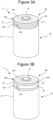
- FIG. 3A is a perspective view of battery 1 in a normal state
- FIG. 3B is a perspective view of battery 1 when an internal pressure rises (in an abnormal state).
- the groove 23 having a width h in the normal state widens to have a width h' in the abnormal state.
- the upper portion 21b pushes up the end wall 50c via the insulating material 52.
- the end wall 50c is pushed, the portion of the bridge portion 50d connected to the first connection portion 50a is broken, and the negative electrode of the electrode assembly 10 is disconnected from the second connection portion 50b, which is an external negative electrode terminal, and the end wall 50c. That is, the current from the battery 1 is cut off.
- the electrode terminal 50 is made of a conductive material such as a nickel-plated steel plate, an aluminum hot-dip plated steel plate, aluminum, or an aluminum alloy to function as an external terminal (a negative electrode external terminal in this case).
- the insulating material 52 can be formed of a resin material such as an epoxy resin to function as an adhesive.
- the electrode terminal 50 may be formed by joining two of the first connection portion 50a, the second connection portion 50b, and the bridge portion 50d by welding or the like.
- first connection portion 50a and the cylindrical portion 21 of the outer can 20 can be connected to each other by laser welding or the like, and various means such as electron beam welding, brazing, resistance welding, friction stir welding, and ultrasonic welding can be adopted.
- the first connection portion 50a may be connected to the cylindrical portion 21 of the outer can 20 over the entire circumference or in discrete areas by spot welding or the like.
- the cross section perpendicular to the axial direction of the bridge portion 50d has an area smaller than those of the first connection portion 50a and the second connection portion 50b.
- the bridge portion 50d is thinner than the first connection portion 50a and the second connection portion 50b. This is to adjust a place where mechanical strength and stress are concentrated within a range in which the bridge portion 50d has no problem as a current path in a normal state.
- the size and shape of the bridge portion 50d may be adjusted so that the bridge portion 50d is broken at an appropriate timing.
- the dimension in the direction (width direction) perpendicular to the extending direction of the bridge portion 50d may be smaller than the dimensions in the direction perpendicular to the axial direction of the first connection portion 50a and the second connection portion 50b.
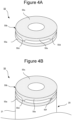
- FIG. 4A illustrates an example in which four bridge portions 50d are provided.
- the bridge portion 50d can be cut by laser processing or mechanical processing using a cutting tool or the like.
- a protrusion can be formed on at least one of the first connection portion 50a and the second connection portion 50b in such a manner as to protrude toward the other connection portion in the axial direction.
- the tip of the protrusion is separated from the other connection portion.
- the protrusion overlaps the bridge portion 50d in the circumferential direction of the outer can 20.
- the above-described processing is not essential.
- FIG. 4B illustrates one bridge portion 50d in a cut state after being attached to the outer can 20.
- a trace (cutting mark) 50f usually remains.
- FIG. 5 is a view illustrating another example of the bridge portion 50d.
- the bridge portion 50d has a thin plate shape with a constant width, and the portion connected to the second connection portion 50b and the portion connected to the first connection portion 50a have the same length.
- FIG. 6 is a view illustrating the bridge portion 50d in other examples.
- the bridge portion 50d which is similar to that described with reference to FIG. 2 , expands upward with both sides being curved to be concave inward, and is smoothly connected to the second connection portion 50b.
- the bridge portion 50d has a trapezoidal shape with both sides being straight.
- the bridge portion 50d has a shape in which a width of a central portion thereof in the vertical direction is narrowest as if two trapezoids are connected.
- the bridge portion 50d has a width that is narrowest at a central portion thereof similarly to that in FIG. 6C , but both sides of the bridge portion 50d are curved with central portions thereof being concave.
- Such a bridge portion 50d can also be broken when the outer can 20 is expanded, thereby cutting off current.
- FIGS. 7A and 7B are views illustrating the bridge portion 50d in another example.
- FIG. 7A is a schematic view illustrating a shape of the bridge portion 50d
- FIG. 7B is a cross-sectional view illustrating the battery 1 including the bridge portion 50d.
- a partial portion (a central portion in the vertical direction) of the bridge portion 50d is thinner than the other portions (portions close to upper and lower ends) of the bridge portion 50d.
- the thinner portion can be formed by, for example, pressing.
- the thinner portion may be formed by irradiating a region to be thinner with a laser, and shaving (trimming) a partial portion of the region.
- the bridge portion 50d is made of aluminum, the bridge portion 50d can be easily trimmed with a laser.
- the insulating material 52 is omitted. Therefore, the second connection portion 50b is also in contact with the outer can 20. In a case where the bridge portion 50d has a function of fusing resulting from an overcurrent, the insulating material 52 that insulates the outer can 20 and the second connection portion 50b from each other may be provided as in the example of FIG. 1 .
- FIGS. 8A and 8B illustrate the bridge portion 50d in other examples.
- the bridge portion 50d has a shape in which a central portion thereof in the vertical direction is concave from both sides, and both sides of the connection portion between the bridge portion 50d and the second connection portion 50b and both sides of the connection portion between the bridge portion 50d and the first connection portion 50a are concave in a semicircular shape.
- FIG. 8B similarly to FIG.
- both sides of the connection portion between the bridge portion 50d and the second connection portion 50b and both sides of the connection portion between the bridge portion 50d and the first connection portion 50a are concave in a semicircular shape, but the position of the portion of the bridge portion 50d connected to the second connection portion 50b and the position of the portion of the bridge portion 50d connected to the first connection portion 50a are different in the circumferential direction of the outer can 20. Therefore, an intermediate portion extending in the circumferential direction is formed at the central portion of the bridge portion 50d in the vertical direction. In addition, semicircular depressions are formed in base portions (bent portions) of the intermediate portion extending in the circumferential direction.
- FIGS. 8A and 8B are particularly suitable for fusing resulting from an overcurrent (large current). That is, when the battery current becomes excessive, the current flowing through the bridge portion 50d becomes excessive, and accordingly, the bridge portion 50d is heated to a high temperature and fused.
- the electrode terminal 50 may be made of aluminum or an aluminum alloy.
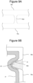
- FIGS. 9A and 9B are views illustrating the bridge portion 50d in another example.
- FIG. 7A is a schematic view illustrating a shape of the bridge portion 50d
- FIG. 7B is a cross-sectional view illustrating the battery 10 including the bridge portion 50d.
- the bridge portion 50d extends in the diameter direction (the thickness direction of the bridge portion) as well as the circumferential direction and the axial direction of the battery 10. With this configuration, even if the space in the circumferential direction or the axial direction is limited, the distance (length) of the bridge portion 50d can be stably secured.
- the bridge portion 50d extends in the diameter direction along the surface of the groove 23 so as to be accommodated in the depression of the groove 23 of the outer can 20.
- the surface of the bridge portion 50d extending in the diameter direction may be covered with, for example, a potting material such as a resin.
- a potting material such as a resin.
- the potting material can suppress corrosion of the bridge portion 50d. By suppressing corrosion, it is possible to suppress current interruption at the bridge portion 50d at an earlier timing.
- the bridge portion 50d covered with the potting material does not need to be positioned to face the groove 23.
- the insulating material 52 that insulates the outer can 20 and the second connection portion 50b from each other may be provided.
- the present embodiment adopts a configuration in which current is collected from both the positive electrode terminal and the negative electrode terminal of the battery are collected at one end.
- the aforementioned structure is adopted for the electrode terminal 50 on the negative electrode side.
- the polarity of the battery can be reversed, and the bridge portion 50d can be provided in the electrode terminal 50 on the positive electrode side.
Landscapes
- Chemical & Material Sciences (AREA)
- Chemical Kinetics & Catalysis (AREA)
- Electrochemistry (AREA)
- General Chemical & Material Sciences (AREA)
- Engineering & Computer Science (AREA)
- Power Engineering (AREA)
- Microelectronics & Electronic Packaging (AREA)
- Manufacturing & Machinery (AREA)
- Connection Of Batteries Or Terminals (AREA)
- Secondary Cells (AREA)
Abstract
Description
- The present disclosure relates to a power storage device having a current interrupting function.
- In an electric vehicle or the like, it is necessary to mount a large-capacity battery, and the number of batteries that make up one unit is also large. When an abnormality occurs in an individual battery, the internal pressure may increase due to gas generation. For this reason, it is usual that a mechanism for releasing gas is provided in an individual battery, but it is preferable to cut off a current in the battery when an abnormality occurs. Therefore, it has been proposed to provide a mechanism for cutting off a current when an abnormality occurs in a battery (hereinafter, a current interruption device (CID)).
- For example, in
Patent Literature 1, a pair of holding plates that adhere to each other is provided on an exterior component of a battery, and a fragile element forming a conductive path is connected between the two holding plates. Then, the element is broken when the exterior component expands, thereby cutting off a current. - Patent Literature 1:
JP 2001-196049 A - In
Patent Literature 1, the holding plates and the element are specially provided on the exterior component of the battery. Therefore, there is a problem that the number of components increases, which increases the cost, and when batteries are stacked, the external sizes of the batteries increases. - Note that, instead of the CID, an electric circuit interruption mechanism that monitors a battery voltage and interrupts a current when an abnormality is detected from the detected value of the battery voltage may be provided, but there are many cases where a current cannot be sufficiently interrupted in response to an abnormality of an individual battery.
- A power storage device according to the present disclosure includes: an electrode assembly including a first electrode and a second electrode; an outer can including a cylindrical portion, a bottom portion provided at one end of the cylindrical portion in an axial direction, and an opening formed at the other end of the cylindrical portion in the axial direction, the outer can accommodating the electrode assembly; a sealing assembly closing the opening; and an electrode terminal electrically connected to the outer can, in which an annular groove positioned between the electrode assembly and the sealing plate is formed on an outer circumferential surface of the cylindrical portion, the electrode terminal includes, an outer surface of the outer can, a first connection portion joined to a side closer to the bottom portion than the groove, a second connection portion positioned on a side closer to the opening than the groove, and a bridge portion connecting the first connection portion and the second connection portion to each other, and the groove expands in the axial direction due to expansion of the outer can, so that the bridge portion is broken to cut off a current between the first connection portion and the second connection portion.
- The second connection portion may include a side wall connected to the bridge portion at one end thereof and extending in the axial direction, and an end wall connected to the other end of the side wall and extending in a diameter direction inward of the sealing assembly, and the end wall may cover an end surface of the cylindrical battery in the axial direction.
- The side wall may have a cylindrical shape, and the end wall may be an annular disk.
- An insulating member may be interposed between the second connection portion and the outer can, and the second connection portion may be fixed to a side closer to the opening than the groove of the cylindrical portion via the insulating member.
- The bridge portion may have a smaller area of a cross section perpendicular to the axial direction than the first connection portion and the second connection portion.
- The bridge portion may be thinner than the first connection portion and the second connection portion.
- The bridge portion may have a dimension in a width direction that decreases from the second connection portion toward the first connection portion in the axial direction.
- The bridge portion may be fused in a case where a large current flows.
- One of the first connection portion and the second connection portion may have a protrusion extending toward the other connection portion with a tip thereof being separated from the other connection portion in the axial direction, and the protrusion may overlap the bridge portion in a circumferential direction of the outer can.
- According to the present disclosure, a CID can be provided in each individual cylindrical battery with a relatively simple configuration, and a current can be reliably cut off when an abnormality occurs.
-
-
FIG. 1 is a cross-sectional view of a cylindrical battery as an example of an embodiment. -
FIG. 2 is a perspective view illustrating a configuration of an electrode terminal. -
FIG. 3A is a perspective view of a cylindrical battery in a normal state. -
FIG. 3B is a perspective view of a cylindrical battery, when an internal pressure increases (in an abnormal state). -
FIG. 4A is a view illustrating an example of a configuration of a bridge portion when four bridge portions are provided. -
FIG. 4B is a view illustrating an example of a configuration of a bridge portion a state in which the bridge portion is cut. -
FIG. 5 is a view illustrating a bridge portion in another example. -
FIG. 6A is a view illustrating a bridge portion in another example. -
FIG. 6B is a view illustrating a bridge portion in another example. -
FIG. 6C is a view illustrating a bridge portion in another example. -
FIG. 6D is a view illustrating a bridge portion in another example. -
FIG. 7A is a view illustrating a shape of a bridge portion in another example (an example in which a thin wall is used). -
FIG. 7B is a view illustrating a cross section of a bridge portion in another example (an example in which a thin wall is used). -
FIG. 8A is a view illustrating a bridge portion in another example (an example suitable for fusing resulting from a large current). -
FIG. 8B is a view illustrating a bridge portion in another example (an example suitable for fusing resulting from a large current). -
FIG. 9A is a view illustrating a shape of a bridge portion in another example (an example in which the bridge portion is concave in a diameter direction). -
FIG. 9B is a view illustrating a cross section of a bridge portion in another example (an example in which the bridge portion is concave in a diameter direction). - Hereinafter, an example of an embodiment of a cylindrical battery will be described in detail as an example of a power storage device according to the present disclosure with reference to the drawings. Note that the present disclosure includes a configuration obtained by selectively combining a plurality of embodiments and modifications to be described below. The power storage device according to the present disclosure is not limited to the cylindrical battery, and may be another electrochemical element such as a capacitor using a cylindrical outer can electrically connected to an electrode assembly.
-
FIG. 1 is a cross-sectional view of abattery 1 which is an example of a power storage device according to an embodiment. Thebattery 1 includes anelectrode assembly 10, anouter can 20 that has a cylindrical portion, a bottom portion at one end of the cylindrical portion in an axial direction, and an opening at the other end of the cylindrical portion to accommodate theelectrode assembly 10, and asealing assembly 30 that closes the opening of theouter can 20. An electrolytic solution is accommodated in theouter can 20 together with theelectrode assembly 10. The electrolytic solution may be an aqueous electrolytic solution, but a non-aqueous electrolytic solution is used in the present embodiment. The outer can 20 has anannular groove 23 formed in thecylindrical portion 21, and the sealingassembly 30 is supported by thegroove 23 to close the opening of theouter can 20. Hereinafter, for convenience of description, a side of thebattery 1 where the sealingassembly 30 is located will be referred to as an upper side, and a side of thebattery 1 where thebottom portion 22 of theouter can 20 will be referred to as a lower side. - The
battery 1 further includes an electrode lead extending from an upper end of theelectrode assembly 10 in the axial direction and directly connecting a first electrode constituting theelectrode assembly 10 and acurrent collecting plate 32 of the sealingassembly 30, and an upper insulatingplate 40 disposed between theelectrode assembly 10 and the sealingassembly 30. Theelectrode assembly 10 is a winding-type electrode assembly in which a first electrode and a second electrode are wound with a separator interposed therebetween. In the present embodiment, the first electrode is a positive electrode, the second electrode is a negative electrode, and the electrode lead is apositive electrode lead 12. - The
positive electrode lead 12 electrically connects the positive electrode and the sealingassembly 30 to each other, and the negative electrode lead electrically connects the negative electrode and theouter can 20 to each other. Therefore, the sealingassembly 30 functions as a positive electrode external terminal, and the outer can 20 functions as a negative electrode terminal. The upper insulatingplate 40 prevents the positive electrode and thepositive electrode lead 12 from coming into contact with theouter can 20, and also prevents thepositive electrode lead 12 from coming into contact with the negative electrode of theelectrode assembly 10. The positive electrode and the negative electrode may be formed to have exposed portions, which are partial portions of cores of electrode plates exposed from composite layers protruding in the axial direction may be formed, and these exposed portions may be joined to the current collecting plate (not illustrated) by welding, and electrically connected to the sealingassembly 30 and theouter can 20 via the current collecting plate. - The positive electrode, the negative electrode, and the separator of the
electrode assembly 10 are all band-like long members, and are spirally wound so as to be alternately stacked in a diameter direction of theelectrode assembly 10. The composite layer of the negative electrode may be formed to have a size slightly larger than that of the composite layer of the positive electrode in order to prevent precipitation of lithium. That is, the composite layer of the negative electrode may be formed to be longer than the composite layer of the positive electrode in the longitudinal direction and the width direction (short-length direction). The separator is formed to have a size slightly larger than that of at least the positive electrode, and for example, two separators are disposed so as to sandwich the positive electrode therebetween. - The positive electrode includes a positive electrode core and a positive composite layer formed on at least one surface of the positive electrode core. As the positive electrode core, a foil of a metal, e.g., aluminum or an aluminum alloy, which is stable in a potential range of the positive electrode, a film in which the metal is disposed on a surface layer thereof, or the like can be used. The positive composite layer includes, for example, a positive electrode active material, a conductive agent such as acetylene black, and a binder such as polyvinylidene fluoride, and is preferably formed on both surfaces of the positive electrode core. As the positive electrode active material, for example, a lithium-transition metal composite oxide is used. The
positive electrode lead 12 is connected to the positive electrode, but is preferably directly joined to the positive electrode core by welding or the like. - The negative electrode includes a negative electrode core and a negative composite layer formed on at least one surface of the negative electrode core. As the negative electrode core, for example, a foil of a metal, e.g., copper or a copper alloy, which is stable in a potential range of the negative electrode, a film in which the metal is disposed on a surface layer thereof, or the like can be used. The negative composite layer includes, for example, a negative electrode active material and a binder such as styrene-butadiene rubber (SBR), and is preferably formed on both surfaces of the negative electrode core. As the negative electrode active material, for example, graphite, a silicon-containing compound, or the like is used. The negative electrode lead is preferably directly joined to the negative electrode core by welding or the like. It is also possible to electrically connect the negative electrode core and the
outer can 20, not through the negative electrode lead. - The non-aqueous electrolyte accommodated in the
outer can 20 includes a non-aqueous solvent and an electrolyte salt dissolved in the non-aqueous solvent. As the non-aqueous solvent, for example, esters, ethers, nitriles, amides, and mixed solvents of two or more thereof are used. The non-aqueous solvent may contain a halogen-substituted product in which at least some of hydrogen in any of the solvents described above is substituted with a halogen atom such as fluorine. Examples of the non-aqueous solvent include ethylene carbonate (EC), ethyl methyl carbonate (EMC), dimethyl carbonate (DMC), and mixed solvents thereof. As the electrolyte salt, for example, a lithium salt such as LiPF6 is used. The non-aqueous electrolyte may be a gel electrolyte, a solid electrolyte, or the like rather than the electrolytic solution. - The outer can 20 is a bottomed cylindrical metal container having an opening at one end (upper end) in the axial direction, and has a
cylindrical portion 21 formed in a cylindrical shape and abottom portion 22 having a circular shape in a bottom view. The outer can 20 is generally made of a metal containing iron as a main component, but may be made of a metal containing aluminum or the like as a main component in a case where the positive electrode is connected thereto. The outer can 20 has agroove 23 formed along a circumferential direction of thecylindrical portion 21. Thegroove 23 is formed at a position away from an opening edge (an upper end of the outer can 20) by a predetermined length near the opening ofouter can 20. The predetermined length is, for example, a length corresponding to greater than or equal to 1% and less than or equal to 20% of the axial length of theouter can 20. - In the
battery 1 according to the present embodiment, an exhaust valve mechanism that operates when an abnormality occurs in thebattery 1 is provided on thebottom portion 22 of theouter can 20. On the other hand, the sealingassembly 30 is not provided with an exhaust valve mechanism. For example, a thin wall is formed as thebottom portion 22. When an abnormality occurs in thebattery 1 and the internal pressure increases, the thin wall is preferentially broken. A gas discharge port may be formed in thebottom portion 22. In the power storage device according to the present disclosure, the sealingassembly 30 may be provided with a pressure-sensitive current interrupting mechanism separately from the exhaust valve mechanism, a temperature-sensitive current interrupting device, and anelectrode terminal 50. - The
groove 23 is a partial portion of thecylindrical portion 21 protruding inward of theouter can 20, and is formed by, for example, spinning thecylindrical portion 21 from the outside. At the position where thegroove 23 is formed, theouter can 20 is reduced in diameter, and a thin linear groove is formed on the outer circumferential surface of thecylindrical portion 21. It is preferable that thegroove 23 has a substantially U-shaped cross section and is formed in an annular shape over the entire circumferential length of thecylindrical portion 21. Thegroove 23 is preferably formed by processing thecylindrical portion 21 after theelectrode assembly 10 is accommodated in theouter can 20. - An inner diameter of the
outer can 20 at the position where thegroove 23 is formed is, for example, greater than or equal to 80% and less than or equal to 99% of the maximum inner diameter of theouter can 20. An example of a length of thegroove 23 along a diameter direction of theouter can 20 is greater than or equal to 0.5 mm and less than or equal to 2.0 mm. Since the diameter of theelectrode assembly 10 is substantially equal to the maximum inner diameter of theouter can 20, theelectrode assembly 10 and thegroove 23 overlap with each other when viewed in the vertical direction (axial direction) of thebattery 1. In the present embodiment, lower ends of a plurality of positive electrode leads 12 are connected to the positive electrode core at a plurality of places, and upper ends of the positive electrode leads 12 are electrically connected to acap 31 via thecurrent collecting plate 32. Note that the number of positive electrode leads 12 may be one or more. - In the
outer can 20, an outer dimension of a portion closer to the opening than a portion accommodating theelectrode assembly 10 in the axial direction may be smaller than an outer dimension of the portion accommodating theelectrode assembly 10. With this configuration, as an outer shape of theouter can 20, the portion closer to the opening of theouter can 20 is recessed from the other portion of theouter can 20. By accommodating theelectrode terminal 50 in this recess, it is possible to suppress protrusion of theelectrode terminal 50 from theouter can 20 in the diameter direction and to suppress an increase in size of thebattery 1 in the diameter direction. - The sealing
assembly 30 includes acap 31, acurrent collecting plate 32, and agasket 33, and is formed in a disk shape as a whole. The sealingassembly 30 is disposed on thegroove 23 of theouter can 20, and is fixed to the upper end of theouter can 20. An upper end of the opening of theouter can 20 is bent inward in the diameter direction and caulked to the sealingassembly 30. In other words, the sealingassembly 30 is fixed to the upper end of theouter can 20 by thegroove 23 and the caulking portion of theouter can 20 to close the opening of theouter can 20. The caulking portion is formed in an annular shape along the circumferential direction of theouter can 20, and sandwiches the sealingassembly 30 in the axial direction together with thegroove 23. - The
cap 31 is a disk-shaped metal member, and is exposed to the outside of theouter can 20 and forms a top surface of thebattery 1. Thecap 31 has a shape (raised portion) in which a central portion in the diameter direction protrudes outward of thebattery 1. A wiring member is connected to thecap 31 when thebattery 1 is modularized to form an assembled battery. For this reason, thecap 31 functions as an external terminal of thebattery 1, and is also called an external terminal or a top cover. In thebattery 1 according to the present embodiment, thepositive electrode lead 12 is connected to thecurrent collecting plate 32, and thecap 31 functions as a positive electrode external terminal. - The
current collecting plate 32 is a metal member having substantially the same diameter as thecap 31, and is disposed closer to theelectrode assembly 10 than thecap 31. Thecurrent collecting plate 32 has anopening 32a at a central portion thereof in the diameter direction, and is formed in an annular shape. Thecap 31 and thecurrent collecting plate 32 are welded to each other, and thecurrent collecting plate 32 is welded, for example, at a position closer to an outer circumferential edge than the center in the diameter direction of thecap 31. Thecurrent collecting plate 32 has aprojection 32b to be described later, and theprojection 32b is a portion welded to thecap 31. Since thepositive electrode lead 12 connected to the positive electrode of theelectrode assembly 10 is connected to thecurrent collecting plate 32 as described above, thecurrent collecting plate 32 functions as a positive electrode current collecting plate. - The
gasket 33 is provided between an outer circumferential portion of a laminate in which thecap 31 and thecurrent collecting plate 32 are formed and theouter can 20. Thegasket 33 is a rubber member or a resin member for preventing thecap 31 and thecurrent collecting plate 32 from coming into contact with theouter can 20 to ensure electrical insulation between theouter can 20 and the sealingassembly 30. Thegasket 33 covers an upper surface of thecap 31, side surfaces of thecap 31 and thecurrent collecting plate 32, and a lower surface of thecurrent collecting plate 32 on the outer circumferential portion of the laminate. Thegasket 33 seals the inside of thebattery 1 by closing a gap between theouter can 20 and the sealingassembly 30. - The
gasket 33 is an annular resin member, is formed to cover most of the lower surface of thecurrent collecting plate 32, and is interposed between thecurrent collecting plate 32 and the upper insulatingplate 40. Thegasket 33 has anopening 33a formed in a central portion thereof in the diameter direction so as to overlap with theopening 32a of thecurrent collecting plate 32 in the vertical direction. Thegasket 33 may have a throughhole 33b formed in a portion located below thecurrent collecting plate 32. Although it is assumed that an electrolytic solution is accumulated on the upper surface of thegasket 33, the electrolytic solution can be efficiently returned toward theelectrode assembly 10 by providing the throughhole 33b. For example, a plurality of throughholes 33b are formed along the circumferential direction of thegasket 33. Further, thegasket 33 has anannular portion 33c to cover from an outer circumferential portion to a skirt portion of the raised portion of thecap 31. - The
battery 1 has a current interruption device (CID) at the negative electrode terminal. That is, the cap-shapedelectrode terminal 50 functions as a CID. - Here, the
outer can 20 has anannular groove 23 in thecylindrical portion 21 as described above. A portion of thecylindrical portion 21 lower than thegroove 23 will be referred to as alower portion 21a of thecylindrical portion 21, and a portion of thecylindrical portion 21 higher than thegroove 23 will be referred to as anupper portion 21b of thecylindrical portion 21. -
FIG. 2 is a perspective view illustrating theelectrode terminal 50. As illustrated inFIG. 1 , theelectrode terminal 50 includes afirst connection portion 50a surrounding thelower portion 21a from thegroove 23 on a side close to the bottom portion, asecond connection portion 50b surrounding theupper portion 21b, which is a portion toward the opening from thegroove 23, and abridge portion 50d which is a thin passage connecting thefirst connection portion 50a and thesecond connection portion 50b to each other. - The
first connection portion 50a is joined to thelower portion 21a of theouter can 20 to be electrically connected to theouter can 20. - The
second connection portion 50b is disposed on theouter can 20 and theupper portion 21b. Thesecond connection portion 50b is disposed on theupper portion 21b with an insulatingmaterial 52 interposed therebetween. Thesecond connection portion 50b includes acylindrical side wall 50e extending in the axial direction and anannular end wall 50c extending inward in the diameter direction of theside wall 50e. - The
bridge portion 50d has a trapezoidal shape (a shape close to a triangle) in which a portion connected to thesecond connection portion 50b is long and a portion connected to thefirst connection portion 50a is short, and the portion connected to thefirst connection portion 50a is easily broken. Thefirst connection portion 50a and thesecond connection portion 50b do not need to be annular. Thebridge portion 50d may extend so as to cover an area equal to or less than half the circumferences of theouter can 20 and the sealingassembly 30 in the circumferential direction. The surfaces of thefirst connection portion 50a and thesecond connection portion 50b facing theouter can 20 may not be curved surfaces along the side surface of theouter can 20. For example, the surfaces of thefirst connection portion 50a and thesecond connection portion 50b may be flat surfaces. One end of thefirst connection portion 50a may be joined to thebottom portion 22. Thefirst connection portion 50a joined to thebottom portion 22 may have a bending point in the middle in the long-length direction, one end side from the bending point may face thebottom portion 22, and the other end side from the bending point may face the outer circumferential surface of thecylindrical portion 21. - When the
second connection portion 50b is disposed only at theupper portion 21b in the axial direction, a partial portion of thefirst connection portion 50a and thebridge portion 50d may extend to theupper portion 21b. Also, when thefirst connection portion 50a is disposed only at thelower portion 21a, a partial portion of thesecond connection portion 50b and thebridge portion 50d may extend to theupper portion 21b. - When the
side wall 50e is fixed to the upper portion of theouter can 20 via the insulating member, thesecond connection portion 50b may have only theside wall 50e without theend wall 50c. At least one of thefirst connection portion 50a, thesecond connection portion 50b, and thebridge portion 50d may be formed of two pieces. - In this example, two
bridge portions 50d are provided at positions different by 180 degrees from each other. The number ofbridge portions 50d is not limited. There may be only onebridge portion 50d as long as thebridge portion 50d functions as a CID or a current collecting path in a normal state. - The insulating
material 52 is disposed between thesecond connection portion 50b, theend wall 50c, and theouter can 20. Accordingly, only thefirst connection portion 50a is electrically connected to thecylindrical portion 21 of theouter can 20 in a direct manner. Therefore, in a case where theend wall 50c or thesecond connection portion 50b is used as an external terminal, a current path between the negative electrode of theelectrode assembly 10 and the external terminal passes through thebridge portion 50d. -
FIG. 3A is a perspective view ofbattery 1 in a normal state, andFIG. 3B is a perspective view ofbattery 1 when an internal pressure rises (in an abnormal state). In this manner, thegroove 23 having a width h in the normal state widens to have a width h' in the abnormal state. As a result, theupper portion 21b pushes up theend wall 50c via the insulatingmaterial 52. As theend wall 50c is pushed, the portion of thebridge portion 50d connected to thefirst connection portion 50a is broken, and the negative electrode of theelectrode assembly 10 is disconnected from thesecond connection portion 50b, which is an external negative electrode terminal, and theend wall 50c. That is, the current from thebattery 1 is cut off. - The
electrode terminal 50 is made of a conductive material such as a nickel-plated steel plate, an aluminum hot-dip plated steel plate, aluminum, or an aluminum alloy to function as an external terminal (a negative electrode external terminal in this case). In addition, the insulatingmaterial 52 can be formed of a resin material such as an epoxy resin to function as an adhesive. Theelectrode terminal 50 may be formed by joining two of thefirst connection portion 50a, thesecond connection portion 50b, and thebridge portion 50d by welding or the like. - In addition, the
first connection portion 50a and thecylindrical portion 21 of theouter can 20 can be connected to each other by laser welding or the like, and various means such as electron beam welding, brazing, resistance welding, friction stir welding, and ultrasonic welding can be adopted. - The
first connection portion 50a may be connected to thecylindrical portion 21 of theouter can 20 over the entire circumference or in discrete areas by spot welding or the like. - In the
battery 1, the cross section perpendicular to the axial direction of thebridge portion 50d has an area smaller than those of thefirst connection portion 50a and thesecond connection portion 50b. For example, thebridge portion 50d is thinner than thefirst connection portion 50a and thesecond connection portion 50b. This is to adjust a place where mechanical strength and stress are concentrated within a range in which thebridge portion 50d has no problem as a current path in a normal state. At the time when thegroove 23 widens in an abnormal state, the size and shape of thebridge portion 50d may be adjusted so that thebridge portion 50d is broken at an appropriate timing. As well as forming thebridge portion 50d thin, the dimension in the direction (width direction) perpendicular to the extending direction of thebridge portion 50d may be smaller than the dimensions in the direction perpendicular to the axial direction of thefirst connection portion 50a and thesecond connection portion 50b. -
FIG. 4A illustrates an example in which fourbridge portions 50d are provided. By increasing the number ofbridge portions 50d in this manner, the strength of theelectrode terminal 50 increases. Therefore, a large number ofbridge portions 50d can be used at the time of attaching theelectrode terminal 50 to theouter can 20, and some of thebridge portions 50d can be cut after the attachment is completed to make the number ofbridge portions 50d appropriate. Thebridge portion 50d can be cut by laser processing or mechanical processing using a cutting tool or the like. By performing such processing, a protrusion can be formed on at least one of thefirst connection portion 50a and thesecond connection portion 50b in such a manner as to protrude toward the other connection portion in the axial direction. In addition, the tip of the protrusion is separated from the other connection portion. In addition, the protrusion overlaps thebridge portion 50d in the circumferential direction of theouter can 20. In the power storage device according to the present disclosure, the above-described processing is not essential. -
FIG. 4B illustrates onebridge portion 50d in a cut state after being attached to theouter can 20. When thebridge portion 50d is cut in this manner, a trace (cutting mark) 50f usually remains. -
FIG. 5 is a view illustrating another example of thebridge portion 50d. In this example, thebridge portion 50d has a thin plate shape with a constant width, and the portion connected to thesecond connection portion 50b and the portion connected to thefirst connection portion 50a have the same length. -
FIG. 6 is a view illustrating thebridge portion 50d in other examples. InFIG. 6A , thebridge portion 50d, which is similar to that described with reference toFIG. 2 , expands upward with both sides being curved to be concave inward, and is smoothly connected to thesecond connection portion 50b. InFIG. 6B , thebridge portion 50d has a trapezoidal shape with both sides being straight. InFIG. 6C , thebridge portion 50d has a shape in which a width of a central portion thereof in the vertical direction is narrowest as if two trapezoids are connected. InFIG. 6D , thebridge portion 50d has a width that is narrowest at a central portion thereof similarly to that inFIG. 6C , but both sides of thebridge portion 50d are curved with central portions thereof being concave. - Such a
bridge portion 50d can also be broken when theouter can 20 is expanded, thereby cutting off current. -
FIGS. 7A and 7B are views illustrating thebridge portion 50d in another example.FIG. 7A is a schematic view illustrating a shape of thebridge portion 50d, andFIG. 7B is a cross-sectional view illustrating thebattery 1 including thebridge portion 50d. - In this example, a partial portion (a central portion in the vertical direction) of the
bridge portion 50d is thinner than the other portions (portions close to upper and lower ends) of thebridge portion 50d. The thinner portion can be formed by, for example, pressing. Alternatively, the thinner portion may be formed by irradiating a region to be thinner with a laser, and shaving (trimming) a partial portion of the region. When thebridge portion 50d is made of aluminum, thebridge portion 50d can be easily trimmed with a laser. - In this example, the insulating
material 52 is omitted. Therefore, thesecond connection portion 50b is also in contact with theouter can 20. In a case where thebridge portion 50d has a function of fusing resulting from an overcurrent, the insulatingmaterial 52 that insulates theouter can 20 and thesecond connection portion 50b from each other may be provided as in the example ofFIG. 1 . -
FIGS. 8A and 8B illustrate thebridge portion 50d in other examples. InFIG. 8A , thebridge portion 50d has a shape in which a central portion thereof in the vertical direction is concave from both sides, and both sides of the connection portion between thebridge portion 50d and thesecond connection portion 50b and both sides of the connection portion between thebridge portion 50d and thefirst connection portion 50a are concave in a semicircular shape. InFIG. 8B , similarly toFIG. 8A , both sides of the connection portion between thebridge portion 50d and thesecond connection portion 50b and both sides of the connection portion between thebridge portion 50d and thefirst connection portion 50a are concave in a semicircular shape, but the position of the portion of thebridge portion 50d connected to thesecond connection portion 50b and the position of the portion of thebridge portion 50d connected to thefirst connection portion 50a are different in the circumferential direction of theouter can 20. Therefore, an intermediate portion extending in the circumferential direction is formed at the central portion of thebridge portion 50d in the vertical direction. In addition, semicircular depressions are formed in base portions (bent portions) of the intermediate portion extending in the circumferential direction. By elongating thebridge portion 50d in this manner, it is possible to form a bridge portion that can be fused without significantly increasing the dimension of thebridge portion 50d in the axial direction. - The examples of
FIGS. 8A and 8B are particularly suitable for fusing resulting from an overcurrent (large current). That is, when the battery current becomes excessive, the current flowing through thebridge portion 50d becomes excessive, and accordingly, thebridge portion 50d is heated to a high temperature and fused. In this case, theelectrode terminal 50 may be made of aluminum or an aluminum alloy. By covering thebridge portion 50d with a resin such as a polyimide film, the heat dissipation property may be reduced at a portion to be fused to adjust the fusing characteristics. -
FIGS. 9A and 9B are views illustrating thebridge portion 50d in another example.FIG. 7A is a schematic view illustrating a shape of thebridge portion 50d, andFIG. 7B is a cross-sectional view illustrating thebattery 10 including thebridge portion 50d. In this example, thebridge portion 50d extends in the diameter direction (the thickness direction of the bridge portion) as well as the circumferential direction and the axial direction of thebattery 10. With this configuration, even if the space in the circumferential direction or the axial direction is limited, the distance (length) of thebridge portion 50d can be stably secured. - In this example, the
bridge portion 50d extends in the diameter direction along the surface of thegroove 23 so as to be accommodated in the depression of thegroove 23 of theouter can 20. - In addition, the surface of the
bridge portion 50d extending in the diameter direction may be covered with, for example, a potting material such as a resin. In the illustrated example, in a case where thebridge portion 50d is at the position of thegroove 23, thegroove 23 is filled with a potting material. - In a case where the electrode terminal is made of a corrosion-prone material such as aluminum, which is easily corroded by chloride ions, the potting material can suppress corrosion of the
bridge portion 50d. By suppressing corrosion, it is possible to suppress current interruption at thebridge portion 50d at an earlier timing. - The
bridge portion 50d covered with the potting material does not need to be positioned to face thegroove 23. - In this example as well, the insulating
material 52 that insulates theouter can 20 and thesecond connection portion 50b from each other may be provided. - In an electric vehicle or the like, it is necessary to mount a large-capacity battery, and batteries that make up one unit are also becoming larger. When such a large battery is packaged, it is often more efficient to pull out cables from one end of the package. Therefore, the present embodiment adopts a configuration in which current is collected from both the positive electrode terminal and the negative electrode terminal of the battery are collected at one end. In this example, the aforementioned structure is adopted for the
electrode terminal 50 on the negative electrode side. However, the polarity of the battery can be reversed, and thebridge portion 50d can be provided in theelectrode terminal 50 on the positive electrode side. -
- 1
- Battery (power storage device)
- 10
- Electrode assembly
- 12
- Positive electrode lead
- 20
- Outer can
- 21
- Cylindrical portion
- 21a
- Lower portion
- 21b
- Upper portion
- 22
- Bottom portion
- 23
- Groove
- 30
- Sealing assembly
- 31
- Cap
- 32
- Current collecting plate
- 32a
- Opening
- 32b
- Projection
- 33
- Gasket
- 33a
- Opening
- 33b
- Through hole
- 33c
- Doughnut-shaped portion
- 40
- Upper insulating plate
- 50
- Electrode terminal
- 50a
- First connection portion
- 50b
- Second connection portion
- 50c
- End wall
- 50e
- Side wall
- 50d
- Bridge portion
- 52
- Insulating material
Claims (10)
- A power storage device comprising:an electrode assembly including a first electrode and a second electrode;an outer can including a cylindrical portion, a bottom portion provided at one end of the cylindrical portion in an axial direction, and an opening formed at the other end of the cylindrical portion in the axial direction, the outer can accommodating the electrode assembly;a sealing assembly closing the opening; andan electrode terminal electrically connected to the outer can, whereinan annular groove positioned between the electrode assembly and the sealing plate is formed on an outer circumferential surface of the cylindrical portion,the electrode terminal includes, an outer surface of the outer can, a first connection portion joined to a side closer to the bottom portion than the groove, a second connection portion positioned on a side closer to the opening than the groove, and a bridge portion connecting the first connection portion and the second connection portion to each other, andthe groove expands in the axial direction due to expansion of the outer can, so that the bridge portion is broken to cut off a current between the first connection portion and the second connection portion.
- The power storage device according to claim 1, whereinthe second connection portion includes a side wall connected to the bridge portion at one end thereof and extending in the axial direction, and an end wall connected to the other end of the side wall and extending in a diameter direction inward of the sealing assembly, andthe end wall covers an end surface of the cylindrical battery in the axial direction.
- The power storage device according to claim 2, whereinthe side wall has a cylindrical shape, andthe end wall is an annular disk.
- The power storage device according to claim 1, whereinan insulating member is interposed between the second connection portion and the outer can, andthe second connection portion is fixed to a side closer to the opening than the groove of the cylindrical portion via the insulating member.
- The power storage device according to any one of claims 1 to 4, wherein
the bridge portion has a smaller area of a cross section perpendicular to the axial direction than the first connection portion and the second connection portion. - The power storage device according to claim 5, wherein
the bridge portion is thinner than the first connection portion and the second connection portion. - The power storage device according to claim 5, wherein
the bridge portion has a dimension in a width direction that decreases from the second connection portion toward the first connection portion in the axial direction. - The power storage device according to any one of claims 1 to 7, wherein
the bridge portion is fused in a case where a large current flows. - The power storage device according to any one of claims 1 to 7, whereinone of the first connection portion and the second connection portion has a protrusion extending toward the other connection portion with a tip thereof being separated from the other connection portion in the axial direction, andthe protrusion overlaps the bridge portion in a circumferential direction of the outer can.
- The power storage device according to claim 9, wherein
the bridge portion is fused in a case where a large current flows.
Applications Claiming Priority (2)
| Application Number | Priority Date | Filing Date | Title |
|---|---|---|---|
| JP2021214507 | 2021-12-28 | ||
| PCT/JP2022/047581 WO2023127721A1 (en) | 2021-12-28 | 2022-12-23 | Power storage device |
Publications (3)
| Publication Number | Publication Date |
|---|---|
| EP4459785A1 true EP4459785A1 (en) | 2024-11-06 |
| EP4459785A4 EP4459785A4 (en) | 2025-01-22 |
| EP4459785B1 EP4459785B1 (en) | 2025-10-29 |
Family
ID=86999119
Family Applications (1)
| Application Number | Title | Priority Date | Filing Date |
|---|---|---|---|
| EP22915944.7A Active EP4459785B1 (en) | 2021-12-28 | 2022-12-23 | Power storage device |
Country Status (5)
| Country | Link |
|---|---|
| US (1) | US20250055040A1 (en) |
| EP (1) | EP4459785B1 (en) |
| JP (1) | JPWO2023127721A1 (en) |
| CN (1) | CN118414750A (en) |
| WO (1) | WO2023127721A1 (en) |
Families Citing this family (3)
| Publication number | Priority date | Publication date | Assignee | Title |
|---|---|---|---|---|
| JP2025055828A (en) * | 2023-09-27 | 2025-04-08 | トヨタ自動車株式会社 | Energy storage cell |
| WO2025142291A1 (en) * | 2023-12-26 | 2025-07-03 | パナソニックIpマネジメント株式会社 | Non-aqueous electrolyte secondary battery |
| WO2025249103A1 (en) * | 2024-05-31 | 2025-12-04 | パナソニックIpマネジメント株式会社 | Power storage device |
Family Cites Families (11)
| Publication number | Priority date | Publication date | Assignee | Title |
|---|---|---|---|---|
| JP2000331671A (en) * | 1999-05-19 | 2000-11-30 | Sanyo Electric Co Ltd | Electric energy storage device |
| JP2001196049A (en) | 2000-01-07 | 2001-07-19 | Alps Electric Co Ltd | Pressure sensitive current breaker structure for battery |
| KR100966549B1 (en) * | 2008-10-14 | 2010-06-29 | 주식회사 엘지화학 | Cap assembly with improved safety and cylindrical secondary battery containing same |
| JP5459398B2 (en) * | 2010-05-19 | 2014-04-02 | 日産自動車株式会社 | Bipolar secondary battery |
| KR101252981B1 (en) * | 2010-08-05 | 2013-04-15 | 주식회사 엘지화학 | Pouch of improved safety for secondary battery and secondary battery, battery pack using the same |
| JP6696426B2 (en) * | 2014-08-19 | 2020-05-20 | 日本電気株式会社 | Battery having current cutoff function and method of manufacturing the same |
| KR101858317B1 (en) * | 2015-05-07 | 2018-05-15 | 주식회사 엘지화학 | Pouch type secondary battery comprising a current interrupt electrode lead |
| KR102069175B1 (en) * | 2017-01-06 | 2020-01-22 | 주식회사 엘지화학 | Cap Assembly for Cylindrical Secondary Battery Comprising Current Interrupt Device Coated with Insulating Material on Outer Circumference Surface |
| JP7379380B2 (en) * | 2018-12-28 | 2023-11-14 | パナソニックエナジー株式会社 | sealed battery |
| US12347878B2 (en) * | 2019-12-18 | 2025-07-01 | Panasonic Energy Co., Ltd. | Cylindrical battery |
| JP7607214B2 (en) * | 2020-01-31 | 2024-12-27 | パナソニックIpマネジメント株式会社 | Power storage device |
-
2022
- 2022-12-23 WO PCT/JP2022/047581 patent/WO2023127721A1/en not_active Ceased
- 2022-12-23 CN CN202280084039.9A patent/CN118414750A/en active Pending
- 2022-12-23 US US18/723,609 patent/US20250055040A1/en active Pending
- 2022-12-23 JP JP2023570957A patent/JPWO2023127721A1/ja active Pending
- 2022-12-23 EP EP22915944.7A patent/EP4459785B1/en active Active
Also Published As
| Publication number | Publication date |
|---|---|
| US20250055040A1 (en) | 2025-02-13 |
| CN118414750A (en) | 2024-07-30 |
| EP4459785B1 (en) | 2025-10-29 |
| EP4459785A4 (en) | 2025-01-22 |
| WO2023127721A1 (en) | 2023-07-06 |
| JPWO2023127721A1 (en) | 2023-07-06 |
Similar Documents
| Publication | Publication Date | Title |
|---|---|---|
| JP7576747B2 (en) | battery | |
| EP4459785A1 (en) | Power storage device | |
| JP5558569B2 (en) | Battery and battery pack | |
| US12548868B2 (en) | Power storage device | |
| CN101894967B (en) | Rechargeable battery | |
| JP7500678B2 (en) | Prismatic secondary battery | |
| JP6529806B2 (en) | Secondary battery and assembled battery | |
| JP6522418B2 (en) | Rectangular secondary battery, battery assembly using the same, and method of manufacturing the same | |
| JP6699563B2 (en) | Storage element | |
| JP2020107464A (en) | Secondary battery and battery pack | |
| JP2019106274A (en) | Square secondary battery and manufacturing method thereof | |
| JP2015082500A (en) | Secondary battery and battery module | |
| EP3968449A1 (en) | End cap assembly, secondary battery, battery pack, and powered device | |
| JP2005332820A (en) | Secondary battery having electrode assembly | |
| WO2015076137A1 (en) | Current interrupting device and power storage device using same | |
| EP4372900A1 (en) | Cylindrical battery | |
| WO2024143319A1 (en) | Power storage device and power storage module | |
| JP7621956B2 (en) | Secondary battery | |
| JPWO2018062339A1 (en) | Method of manufacturing square secondary battery | |
| EP4459783A1 (en) | Current collector plate and power storage device | |
| WO2024095902A1 (en) | Power storage device | |
| KR102896323B1 (en) | Terminal component and secondary battery | |
| US12469913B2 (en) | Secondary battery | |
| WO2024048246A1 (en) | Power storage device | |
| WO2024190287A1 (en) | Cylindrical battery |
Legal Events
| Date | Code | Title | Description |
|---|---|---|---|
| STAA | Information on the status of an ep patent application or granted ep patent |
Free format text: STATUS: THE INTERNATIONAL PUBLICATION HAS BEEN MADE |
|
| PUAI | Public reference made under article 153(3) epc to a published international application that has entered the european phase |
Free format text: ORIGINAL CODE: 0009012 |
|
| STAA | Information on the status of an ep patent application or granted ep patent |
Free format text: STATUS: REQUEST FOR EXAMINATION WAS MADE |
|
| 17P | Request for examination filed |
Effective date: 20240617 |
|
| AK | Designated contracting states |
Kind code of ref document: A1 Designated state(s): AL AT BE BG CH CY CZ DE DK EE ES FI FR GB GR HR HU IE IS IT LI LT LU LV MC ME MK MT NL NO PL PT RO RS SE SI SK SM TR |
|
| REG | Reference to a national code |
Ref country code: DE Ref legal event code: R079 Free format text: PREVIOUS MAIN CLASS: H01M0050578000 Ipc: H01G0011140000 Ref country code: DE Ref legal event code: R079 Ref document number: 602022024216 Country of ref document: DE Free format text: PREVIOUS MAIN CLASS: H01M0050578000 Ipc: H01G0011140000 |
|
| A4 | Supplementary search report drawn up and despatched |
Effective date: 20241219 |
|
| RIC1 | Information provided on ipc code assigned before grant |
Ipc: H01M 50/593 20210101ALI20241216BHEP Ipc: H01M 50/588 20210101ALI20241216BHEP Ipc: H01M 50/583 20210101ALI20241216BHEP Ipc: H01M 50/56 20210101ALI20241216BHEP Ipc: H01M 50/559 20210101ALI20241216BHEP Ipc: H01M 50/55 20210101ALI20241216BHEP Ipc: H01M 50/547 20210101ALI20241216BHEP Ipc: H01M 50/545 20210101ALI20241216BHEP Ipc: H01M 50/107 20210101ALI20241216BHEP Ipc: H01G 11/78 20130101ALI20241216BHEP Ipc: H01G 11/74 20130101ALI20241216BHEP Ipc: H01G 11/16 20130101ALI20241216BHEP Ipc: H01M 50/578 20210101ALI20241216BHEP Ipc: H01G 11/14 20130101AFI20241216BHEP |
|
| DAV | Request for validation of the european patent (deleted) | ||
| DAX | Request for extension of the european patent (deleted) | ||
| GRAP | Despatch of communication of intention to grant a patent |
Free format text: ORIGINAL CODE: EPIDOSNIGR1 |
|
| STAA | Information on the status of an ep patent application or granted ep patent |
Free format text: STATUS: GRANT OF PATENT IS INTENDED |
|
| RIC1 | Information provided on ipc code assigned before grant |
Ipc: H01M 50/593 20210101ALI20250505BHEP Ipc: H01M 50/588 20210101ALI20250505BHEP Ipc: H01M 50/583 20210101ALI20250505BHEP Ipc: H01M 50/56 20210101ALI20250505BHEP Ipc: H01M 50/559 20210101ALI20250505BHEP Ipc: H01M 50/55 20210101ALI20250505BHEP Ipc: H01M 50/547 20210101ALI20250505BHEP Ipc: H01M 50/545 20210101ALI20250505BHEP Ipc: H01M 50/107 20210101ALI20250505BHEP Ipc: H01G 11/78 20130101ALI20250505BHEP Ipc: H01G 11/74 20130101ALI20250505BHEP Ipc: H01G 11/16 20130101ALI20250505BHEP Ipc: H01M 50/578 20210101ALI20250505BHEP Ipc: H01G 11/14 20130101AFI20250505BHEP |
|
| INTG | Intention to grant announced |
Effective date: 20250602 |
|
| GRAS | Grant fee paid |
Free format text: ORIGINAL CODE: EPIDOSNIGR3 |
|
| GRAA | (expected) grant |
Free format text: ORIGINAL CODE: 0009210 |
|
| STAA | Information on the status of an ep patent application or granted ep patent |
Free format text: STATUS: THE PATENT HAS BEEN GRANTED |
|
| AK | Designated contracting states |
Kind code of ref document: B1 Designated state(s): AL AT BE BG CH CY CZ DE DK EE ES FI FR GB GR HR HU IE IS IT LI LT LU LV MC ME MK MT NL NO PL PT RO RS SE SI SK SM TR |
|
| REG | Reference to a national code |
Ref country code: CH Ref legal event code: F10 Free format text: ST27 STATUS EVENT CODE: U-0-0-F10-F00 (AS PROVIDED BY THE NATIONAL OFFICE) Effective date: 20251029 Ref country code: GB Ref legal event code: FG4D |
|
| REG | Reference to a national code |
Ref country code: IE Ref legal event code: FG4D |
|
| REG | Reference to a national code |
Ref country code: DE Ref legal event code: R096 Ref document number: 602022024216 Country of ref document: DE |
|
| PGFP | Annual fee paid to national office [announced via postgrant information from national office to epo] |
Ref country code: DE Payment date: 20251211 Year of fee payment: 4 |
|
| PGFP | Annual fee paid to national office [announced via postgrant information from national office to epo] |
Ref country code: AT Payment date: 20260113 Year of fee payment: 4 |
|
| PGFP | Annual fee paid to national office [announced via postgrant information from national office to epo] |
Ref country code: FR Payment date: 20251229 Year of fee payment: 4 |
|
| REG | Reference to a national code |
Ref country code: NL Ref legal event code: MP Effective date: 20251029 |
|
| PG25 | Lapsed in a contracting state [announced via postgrant information from national office to epo] |
Ref country code: ES Free format text: LAPSE BECAUSE OF FAILURE TO SUBMIT A TRANSLATION OF THE DESCRIPTION OR TO PAY THE FEE WITHIN THE PRESCRIBED TIME-LIMIT Effective date: 20251029 |
|
| REG | Reference to a national code |
Ref country code: LT Ref legal event code: MG9D |
|
| PG25 | Lapsed in a contracting state [announced via postgrant information from national office to epo] |
Ref country code: NO Free format text: LAPSE BECAUSE OF FAILURE TO SUBMIT A TRANSLATION OF THE DESCRIPTION OR TO PAY THE FEE WITHIN THE PRESCRIBED TIME-LIMIT Effective date: 20260129 |
|
| PG25 | Lapsed in a contracting state [announced via postgrant information from national office to epo] |
Ref country code: AT Free format text: LAPSE BECAUSE OF FAILURE TO SUBMIT A TRANSLATION OF THE DESCRIPTION OR TO PAY THE FEE WITHIN THE PRESCRIBED TIME-LIMIT Effective date: 20251029 Ref country code: HR Free format text: LAPSE BECAUSE OF FAILURE TO SUBMIT A TRANSLATION OF THE DESCRIPTION OR TO PAY THE FEE WITHIN THE PRESCRIBED TIME-LIMIT Effective date: 20251029 Ref country code: FI Free format text: LAPSE BECAUSE OF FAILURE TO SUBMIT A TRANSLATION OF THE DESCRIPTION OR TO PAY THE FEE WITHIN THE PRESCRIBED TIME-LIMIT Effective date: 20251029 |
|
| REG | Reference to a national code |
Ref country code: AT Ref legal event code: MK05 Ref document number: 1852648 Country of ref document: AT Kind code of ref document: T Effective date: 20251029 |
|
| PG25 | Lapsed in a contracting state [announced via postgrant information from national office to epo] |
Ref country code: NL Free format text: LAPSE BECAUSE OF FAILURE TO SUBMIT A TRANSLATION OF THE DESCRIPTION OR TO PAY THE FEE WITHIN THE PRESCRIBED TIME-LIMIT Effective date: 20251029 |
|
| PG25 | Lapsed in a contracting state [announced via postgrant information from national office to epo] |
Ref country code: RS Free format text: LAPSE BECAUSE OF FAILURE TO SUBMIT A TRANSLATION OF THE DESCRIPTION OR TO PAY THE FEE WITHIN THE PRESCRIBED TIME-LIMIT Effective date: 20260129 |
|
| PG25 | Lapsed in a contracting state [announced via postgrant information from national office to epo] |
Ref country code: IS Free format text: LAPSE BECAUSE OF FAILURE TO SUBMIT A TRANSLATION OF THE DESCRIPTION OR TO PAY THE FEE WITHIN THE PRESCRIBED TIME-LIMIT Effective date: 20260228 |
|
| PG25 | Lapsed in a contracting state [announced via postgrant information from national office to epo] |
Ref country code: PT Free format text: LAPSE BECAUSE OF FAILURE TO SUBMIT A TRANSLATION OF THE DESCRIPTION OR TO PAY THE FEE WITHIN THE PRESCRIBED TIME-LIMIT Effective date: 20260302 |
|
| PG25 | Lapsed in a contracting state [announced via postgrant information from national office to epo] |
Ref country code: PL Free format text: LAPSE BECAUSE OF FAILURE TO SUBMIT A TRANSLATION OF THE DESCRIPTION OR TO PAY THE FEE WITHIN THE PRESCRIBED TIME-LIMIT Effective date: 20251029 |
|
| PG25 | Lapsed in a contracting state [announced via postgrant information from national office to epo] |
Ref country code: LV Free format text: LAPSE BECAUSE OF FAILURE TO SUBMIT A TRANSLATION OF THE DESCRIPTION OR TO PAY THE FEE WITHIN THE PRESCRIBED TIME-LIMIT Effective date: 20251029 |