EP4459639A1 - Bus bar - Google Patents
Bus bar Download PDFInfo
- Publication number
- EP4459639A1 EP4459639A1 EP23904828.3A EP23904828A EP4459639A1 EP 4459639 A1 EP4459639 A1 EP 4459639A1 EP 23904828 A EP23904828 A EP 23904828A EP 4459639 A1 EP4459639 A1 EP 4459639A1
- Authority
- EP
- European Patent Office
- Prior art keywords
- bus bar
- insulator
- main body
- bar main
- heat
- Prior art date
- Legal status (The legal status is an assumption and is not a legal conclusion. Google has not performed a legal analysis and makes no representation as to the accuracy of the status listed.)
- Granted
Links
Images


Classifications
-
- H—ELECTRICITY
- H01—ELECTRIC ELEMENTS
- H01B—CABLES; CONDUCTORS; INSULATORS; SELECTION OF MATERIALS FOR THEIR CONDUCTIVE, INSULATING OR DIELECTRIC PROPERTIES
- H01B17/00—Insulators or insulating bodies characterised by their form
- H01B17/56—Insulating bodies
-
- H—ELECTRICITY
- H02—GENERATION; CONVERSION OR DISTRIBUTION OF ELECTRIC POWER
- H02G—INSTALLATION OF ELECTRIC CABLES OR LINES, OR OF COMBINED OPTICAL AND ELECTRIC CABLES OR LINES
- H02G5/00—Installations of bus-bars
- H02G5/02—Open installations
-
- H—ELECTRICITY
- H01—ELECTRIC ELEMENTS
- H01M—PROCESSES OR MEANS, e.g. BATTERIES, FOR THE DIRECT CONVERSION OF CHEMICAL ENERGY INTO ELECTRICAL ENERGY
- H01M50/00—Constructional details or processes of manufacture of the non-active parts of electrochemical cells other than fuel cells, e.g. hybrid cells
- H01M50/50—Current conducting connections for cells or batteries
- H01M50/502—Interconnectors for connecting terminals of adjacent batteries; Interconnectors for connecting cells outside a battery casing
- H01M50/503—Interconnectors for connecting terminals of adjacent batteries; Interconnectors for connecting cells outside a battery casing characterised by the shape of the interconnectors
-
- H—ELECTRICITY
- H01—ELECTRIC ELEMENTS
- H01M—PROCESSES OR MEANS, e.g. BATTERIES, FOR THE DIRECT CONVERSION OF CHEMICAL ENERGY INTO ELECTRICAL ENERGY
- H01M50/00—Constructional details or processes of manufacture of the non-active parts of electrochemical cells other than fuel cells, e.g. hybrid cells
- H01M50/50—Current conducting connections for cells or batteries
- H01M50/502—Interconnectors for connecting terminals of adjacent batteries; Interconnectors for connecting cells outside a battery casing
- H01M50/505—Interconnectors for connecting terminals of adjacent batteries; Interconnectors for connecting cells outside a battery casing comprising a single busbar
-
- H—ELECTRICITY
- H01—ELECTRIC ELEMENTS
- H01M—PROCESSES OR MEANS, e.g. BATTERIES, FOR THE DIRECT CONVERSION OF CHEMICAL ENERGY INTO ELECTRICAL ENERGY
- H01M50/00—Constructional details or processes of manufacture of the non-active parts of electrochemical cells other than fuel cells, e.g. hybrid cells
- H01M50/50—Current conducting connections for cells or batteries
- H01M50/502—Interconnectors for connecting terminals of adjacent batteries; Interconnectors for connecting cells outside a battery casing
- H01M50/521—Interconnectors for connecting terminals of adjacent batteries; Interconnectors for connecting cells outside a battery casing characterised by the material
- H01M50/526—Interconnectors for connecting terminals of adjacent batteries; Interconnectors for connecting cells outside a battery casing characterised by the material having a layered structure
-
- H—ELECTRICITY
- H01—ELECTRIC ELEMENTS
- H01B—CABLES; CONDUCTORS; INSULATORS; SELECTION OF MATERIALS FOR THEIR CONDUCTIVE, INSULATING OR DIELECTRIC PROPERTIES
- H01B5/00—Non-insulated conductors or conductive bodies characterised by their form
- H01B5/02—Single bars, rods, wires, or strips
-
- H—ELECTRICITY
- H01—ELECTRIC ELEMENTS
- H01M—PROCESSES OR MEANS, e.g. BATTERIES, FOR THE DIRECT CONVERSION OF CHEMICAL ENERGY INTO ELECTRICAL ENERGY
- H01M2200/00—Safety devices for primary or secondary batteries
- H01M2200/10—Temperature sensitive devices
Definitions
- the present invention relates to a bus bar whose abnormal heat generation can be detected.
- Non-Patent Literature 1 it is known to use a bus bar in connecting energizable members (for example, a battery installed in an electric vehicle, a hybrid car, etc.).
- energizable members for example, a battery installed in an electric vehicle, a hybrid car, etc.
- Non-Patent Literature 1 it is common to use a plurality of such bus bars when connecting energizable members (for example, a battery installed in an electric vehicle, a hybrid car, etc.).
- Non-Patent Literature 1 " Bus bar”, [online], SUNCALL CORPORATION, [searched on March 1, 2023], Internet (https://www.suncall.co.jp/shunt-sensor-solution/busbar/ )
- the abnormally heated bus bar may fail.
- an object of the present invention is to provide a bus bar that can be simply and easily identified as having generated abnormal heat.
- a bus bar (1) having a bus bar main body (2) and an insulator (3) covering a part of the bus bar main body (2) is characterized in that the insulator (3) has an interior (S) formed hollow and is made of heat-shrinking resin, and the bus bar main body (2) is inserted into the hollow, and an identification member (4, 4A) that can identify the abnormal heat generation when the insulator (3) is heat-shrunk due to abnormal heat generation is provided in the hollow.
- the bus bar (1) set forth in the first aspect is characterized in that the bus bar main body (2) has through holes (left bolt hole 2a1, right bolt hole 2b1) formed at both end sides (left side surface 2a, right side surface 2b), and in fixing a part of the insulator (3) to the bus bar main body (2), the insulator (3) is fixed to the bus bar main body by heat-shrinking both end sides of the insulator so as not to come in contact with the through holes (left bolt hole 2a1, right bolt hole 2b1).
- the identification member (4, 4A) that can identify abnormal heat generation when the insulator (3) is heat-shrunk due to the abnormal heat generation is provided in the hollow of the insulator (3). It is thereby possible to simply and easily identify that the bus bar has generated abnormal heat.
- the insulator (3) since the insulator (3) does not come in contact with the through holes (left bolt hole 2a1, right bolt hole 2b 1), a malfunction such as current not flowing when the energizable members are connected can be prevented.
- bus bar according to an embodiment of the present invention will be specifically described with reference to the drawings. It is noted that, in the following description, when vertical and horizontal directions are indicated, it shall mean vertical and horizontal directions when viewed from the front of the figure.
- a bus bar 1 shown in FIG. 1 can be simply and easily detected to have generated abnormal heat.
- the bus bar 1 shown in FIG. 1 is mainly composed of a bus bar main body 2 and an insulator 3. In the following, each configuration will be described in detail.
- the bus bar main body 2 is made of metal such as copper, and as shown in FIG. 3 , is formed, for example, in the shape of a thick plate with a thickness of about 3 mm to 5 mm, and is formed to be long and rectangular in cross section.
- a left bolt hole 2a1 having a circular shape in plan view (see FIG. 2(b) ) is vertically penetratingly provided on a left side surface 2a side
- a right bolt hole 2b1 having a circular shape in plan view is vertically penetratingly provided on a right side surface 2b side.
- the insulator 3 is made of an insulating material formed of heat-shrinkable resin composed of a thermosetting resin elastomer, etc., and has flexibility. As shown in FIG. 3(a) , such an insulator 3 has an interior S formed hollow and is formed into a rectangular cylindrical shape in cross section, a left side surface 3a and a right side surface 3b thereof are open.
- the bus bar main body 2 is inserted into the interior S of the insulator 3. At this time, the left bolt hole 2a1 is exposed to the outside and located on the left side surface 3a side of the insulator 3, and the right bolt hole 2b1 is exposed to the outside and located on the right side surface 3b side of the insulator 3 (see also FIG. 1(a) ).
- an identification member 4 is provided in the interior S of the insulator 3.
- the identification member 4 is made of metal or the like (including non-metals such as heat-resistant resin and heat-resistant glass) and, as shown in FIG. 3(a) , is formed in a rectangular shape when viewed from the side.
- the identification member 4 has a lower surface 4b fixed slightly on the right side surface 2b side from the center of an upper surface 2c of the bus bar main body 2.
- the identification member 4 has an upper surface 4a shown in FIG. 3(a) carved with the letter M as shown in FIG. 2(b) ("NG" is exemplified in the figure).
- the identification member 4 is preferably made of metal in consideration of thermal conductivity and the like.
- the right side surface 3b side of the insulator 3 is heat-shrunk and fixed to the upper surface 2c and the lower surface 2d on the right side surface 2b side of the bus bar main body 2. Thereby, the insulator 3 is positioned and fixed to the bus bar main body 2.
- bus bar 1 shown in FIG. 1(b) is manufactured in this manner.
- a plurality of bus bars 1 manufactured as described above are used when connecting energizable members (for example, a battery installed in an electric vehicle, a hybrid car, etc.), as described in Non-Patent Literature 1.
- the insulator 3 is heat-shrunk due to the heat, and as shown in FIG. 3(c) , the insulator 3 is completely fixed to the upper surface 2c and the lower surface 2d of the bus bar main body 2.
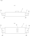
- the insulator 3 comes in close contact with the upper surface 4a of the identification member 4. Therefore, this part appears to be protruding as shown in FIG. 2(a) and the carved letter M ("NG" is exemplified in the figure) stands out from the insulator 3 due to the close contact of the insulator 3 with the upper surface 4a of the identification member 4 as shown in FIG. 2(b) and can be identified from the outside. Accordingly, the abnormally heated bus bar 1 can be simply and easily identified.
- bus bar 1 has generated abnormal heat can be simply and easily identified even when a plurality of bus bars 1 are used.
- the shape and the like shown in the present embodiment are merely examples, and various modifications and changes can be made within the scope of the gist of the present invention described in the claims.
- an example has been shown in which the left side surface 3a side and the right side surface 3b side of the insulator 3 are heat-shrunk and fixed to the bus bar main body 2.
- the present invention is not limited thereto, and any place may be used as long as the insulator 3 can be positioned and fixed to the bus bar main body 2. That is, any place may be used as long as a part of the insulator 3 is fixed to the bus bar main body 2.
- the left side surface 3a side and the right side surface 3b side of the insulator 3 are heat-shrunk and fixed to the bus bar main body 2. This is because a malfunction such as current not flowing between energizable members may occur if the position of the insulator 3 shifts and the insulator 3 hangs over (comes in contact with) the left bolt hole 2a1 and/or the right bolt hole 2b1. Therefore, it is preferable that the left side surface 3a side and the right side surface 3b side of the insulator 3 are heat-shrunk and fixed to the bus bar main body 2.
- the identification member 4 is fixed to the upper surface 2c of the bus bar main body 2.
- the present invention is not limited thereto, and any method may be used as long as abnormal heat generation of the bus bar main body 2 can be identified.
- the letter M (“NG" is exemplified in the figure) stands out for easy identification, but an identification member without the letter M may also be used. Even in this manner, when the insulator 3 comes in close contact with the upper surface 4a of the identification member 4 as shown in FIG. 3(c) , this part appears to be protruding as shown in FIG. 2(a) .
- the bus bar main body 2 can be identified as having generated abnormal heat.
- FIG. 4(a) a spherical identification member 4A is placed in the interior S of the insulator 3 without being fixed.
- the bus bar main body 2 generates abnormal heat
- the insulator 3 is heat-shrunk due to the heat
- the insulator 3 is completely fixed to the upper surface 2c and the lower surface 2d of the bus bar main body 2.
- the insulator 3 comes in close contact with the identification member 4A as shown in FIG.
- the identification members 4, 4A may have any shape, such as a rectangular shape, a spherical shape, a star shape, or a cross shape.
- the present invention can be applied to a flexible bus bar such as a laminated one, a braided wire, or a bundle of electric wires.
Landscapes
- Chemical & Material Sciences (AREA)
- Chemical Kinetics & Catalysis (AREA)
- Electrochemistry (AREA)
- General Chemical & Material Sciences (AREA)
- Installation Of Bus-Bars (AREA)
- Insulators (AREA)
- Insulating Bodies (AREA)
Abstract
Description
- The present invention relates to a bus bar whose abnormal heat generation can be detected.
- In general, it is known to use a bus bar in connecting energizable members (for example, a battery installed in an electric vehicle, a hybrid car, etc.). For example, as described in Non-Patent
Literature 1, it is common to use a plurality of such bus bars when connecting energizable members (for example, a battery installed in an electric vehicle, a hybrid car, etc.). - Non-Patent Literature 1: "Bus bar", [online], SUNCALL CORPORATION, [searched on March 1, 2023], Internet (https://www.suncall.co.jp/shunt-sensor-solution/busbar/)
- Incidentally, when a plurality of bus bars are used as described above, if any one of the plurality of bus bars generates abnormal heat, the abnormally heated bus bar may fail.
- However, at this time, in order to identify which bus bar among the plurality of bus bars has failed, the plurality of bus bars needs to be inspected one by one. This poses a problem that it takes a lot of time and effort to find the failed bus bar.
- Accordingly, in view of the foregoing problem, an object of the present invention is to provide a bus bar that can be simply and easily identified as having generated abnormal heat.
- The foregoing object of the present invention is achieved by the following means. It is noted that reference signs in an embodiment to be described later are added in parentheses, but the present invention is not limited thereto.
- According to a first aspect of the present invention, a bus bar (1) having a bus bar main body (2) and an insulator (3) covering a part of the bus bar main body (2) is characterized in that the insulator (3) has an interior (S) formed hollow and is made of heat-shrinking resin, and the bus bar main body (2) is inserted into the hollow, and an identification member (4, 4A) that can identify the abnormal heat generation when the insulator (3) is heat-shrunk due to abnormal heat generation is provided in the hollow.
- According to a second aspect of the present invention, the bus bar (1) set forth in the first aspect is characterized in that the bus bar main body (2) has through holes (left bolt hole 2a1, right bolt hole 2b1) formed at both end sides (left side surface 2a,
right side surface 2b), and in fixing a part of the insulator (3) to the bus bar main body (2), the insulator (3) is fixed to the bus bar main body by heat-shrinking both end sides of the insulator so as not to come in contact with the through holes (left bolt hole 2a1, right bolt hole 2b1). - Next, advantageous effects of the present invention will be described with reference signs in the drawings. It is noted that reference signs in an embodiment to be described later are added in parentheses, but the present invention is not limited thereto.
- According to the first aspect of the present invention, the identification member (4, 4A) that can identify abnormal heat generation when the insulator (3) is heat-shrunk due to the abnormal heat generation is provided in the hollow of the insulator (3). It is thereby possible to simply and easily identify that the bus bar has generated abnormal heat.
- According to the second aspect of the present invention, since the insulator (3) does not come in contact with the through holes (left bolt hole 2a1,
right bolt hole 2b 1), a malfunction such as current not flowing when the energizable members are connected can be prevented. -
- [
FIG. 1] FIG. 1(a) is a side view showing a state in which an insulator is not heat-shrunk in a bus bar according to an embodiment of the present invention, andFIG. 1(b) is a side view showing a state in which both ends of the insulator are heat-shrunk and fixed to a bus bar main body in the bus bar according to the same embodiment. - [
FIG. 2] FIG. 2 show a state in which the bus bar according to the same embodiment has generated abnormal heat, andFIG. 2(a) is a side view andFIG. 2(b) is a plan view. - [
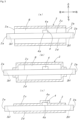
FIG. 3] FIG. 3(a) shows an insulator according to the same embodiment in a longitudinal sectional view and is a side view showing a state in which the bus bar main body is arranged inside the insulator,FIG. 3(b) is a side view showing a state in which both ends of the insulator are fixed to the bus bar main body from the state shown inFIG. 3(a), and FIG. 3(c) is a side view showing a state in which the bus bar main body has generated abnormal heat and the insulator has been completely fixed to the bus bar main body from the state shown inFIG. 3(b) . - [
FIG. 4] FIG. 4(a) shows the insulator according to the same embodiment in a longitudinal sectional view and is a side view in which the bus bar main body is arranged inside the insulator, and then both ends of the insulator are fixed to the bus bar main body, and an identification member according to another embodiment is arranged inside the insulator, andFIG. 4(b) is a side view showing a state in which the bus bar main body has generated abnormal heat and the insulator has been completely fixed to the bus bar main body from the state shown inFIG. 4(a) . - Hereinafter, a bus bar according to an embodiment of the present invention will be specifically described with reference to the drawings. It is noted that, in the following description, when vertical and horizontal directions are indicated, it shall mean vertical and horizontal directions when viewed from the front of the figure.
- A
bus bar 1 shown inFIG. 1 can be simply and easily detected to have generated abnormal heat. Specifically, thebus bar 1 shown inFIG. 1 is mainly composed of a bus barmain body 2 and aninsulator 3. In the following, each configuration will be described in detail. - The bus bar
main body 2 is made of metal such as copper, and as shown inFIG. 3 , is formed, for example, in the shape of a thick plate with a thickness of about 3 mm to 5 mm, and is formed to be long and rectangular in cross section. As shown inFIG. 3 , in the bus barmain body 2, a left bolt hole 2a1 having a circular shape in plan view (seeFIG. 2(b) ) is vertically penetratingly provided on a left side surface 2a side, and a right bolt hole 2b1 having a circular shape in plan view (seeFIG. 2(b) ) is vertically penetratingly provided on aright side surface 2b side. - The
insulator 3 is made of an insulating material formed of heat-shrinkable resin composed of a thermosetting resin elastomer, etc., and has flexibility. As shown inFIG. 3(a) , such aninsulator 3 has an interior S formed hollow and is formed into a rectangular cylindrical shape in cross section, a left side surface 3a and a right side surface 3b thereof are open. - In manufacturing the
bus bar 1 thus configured, first, as shown inFIG. 3(a) , the bus barmain body 2 is inserted into the interior S of theinsulator 3. At this time, the left bolt hole 2a1 is exposed to the outside and located on the left side surface 3a side of theinsulator 3, and the right bolt hole 2b1 is exposed to the outside and located on the right side surface 3b side of the insulator 3 (see alsoFIG. 1(a) ). - Further, as shown in
FIG. 3(a) , anidentification member 4 is provided in the interior S of theinsulator 3. Theidentification member 4 is made of metal or the like (including non-metals such as heat-resistant resin and heat-resistant glass) and, as shown inFIG. 3(a) , is formed in a rectangular shape when viewed from the side. As shown inFIG. 3(a) , theidentification member 4 has alower surface 4b fixed slightly on theright side surface 2b side from the center of anupper surface 2c of the bus barmain body 2. Further, theidentification member 4 has an upper surface 4a shown inFIG. 3(a) carved with the letter M as shown inFIG. 2(b) ("NG" is exemplified in the figure). Theidentification member 4 is preferably made of metal in consideration of thermal conductivity and the like. - Next, from the state shown in
FIG. 3(a) , heat is applied to the left side surface 3a side of theinsulator 3 shown inFIG. 3(a) , and heat is applied to the right side surface 3b side of theinsulator 3 shown inFIG. 3(a) . Thereby, as shown inFIG. 3(b) , the left side surface 3a side of theinsulator 3 is heat-shrunk and fixed to theupper surface 2c and alower surface 2d on the left side surface 2a side of the bus barmain body 2. Further, as shown inFIG. 3(b) , the right side surface 3b side of theinsulator 3 is heat-shrunk and fixed to theupper surface 2c and thelower surface 2d on theright side surface 2b side of the bus barmain body 2. Thereby, theinsulator 3 is positioned and fixed to the bus barmain body 2. - Accordingly, the
bus bar 1 shown inFIG. 1(b) is manufactured in this manner. - Incidentally, a plurality of
bus bars 1 manufactured as described above are used when connecting energizable members (for example, a battery installed in an electric vehicle, a hybrid car, etc.), as described in Non-PatentLiterature 1. - At this time, when the bus bar
main body 2 generates abnormal heat, theinsulator 3 is heat-shrunk due to the heat, and as shown inFIG. 3(c) , theinsulator 3 is completely fixed to theupper surface 2c and thelower surface 2d of the bus barmain body 2. At this time, as shown inFIG. 3(c) , theinsulator 3 comes in close contact with the upper surface 4a of theidentification member 4. Therefore, this part appears to be protruding as shown inFIG. 2(a) and the carved letter M ("NG" is exemplified in the figure) stands out from theinsulator 3 due to the close contact of theinsulator 3 with the upper surface 4a of theidentification member 4 as shown inFIG. 2(b) and can be identified from the outside. Accordingly, the abnormally heatedbus bar 1 can be simply and easily identified. - Thus, by doing so, which
bus bar 1 has generated abnormal heat can be simply and easily identified even when a plurality ofbus bars 1 are used. - Note that the shape and the like shown in the present embodiment are merely examples, and various modifications and changes can be made within the scope of the gist of the present invention described in the claims. For example, in the present embodiment, an example has been shown in which the left side surface 3a side and the right side surface 3b side of the
insulator 3 are heat-shrunk and fixed to the bus barmain body 2. However, the present invention is not limited thereto, and any place may be used as long as theinsulator 3 can be positioned and fixed to the bus barmain body 2. That is, any place may be used as long as a part of theinsulator 3 is fixed to the bus barmain body 2. - However, it is preferable that the left side surface 3a side and the right side surface 3b side of the
insulator 3 are heat-shrunk and fixed to the bus barmain body 2. This is because a malfunction such as current not flowing between energizable members may occur if the position of theinsulator 3 shifts and theinsulator 3 hangs over (comes in contact with) the left bolt hole 2a1 and/or the right bolt hole 2b1. Therefore, it is preferable that the left side surface 3a side and the right side surface 3b side of theinsulator 3 are heat-shrunk and fixed to the bus barmain body 2. - Also, in the present embodiment, an example has been shown in which the
identification member 4 is fixed to theupper surface 2c of the bus barmain body 2. However, the present invention is not limited thereto, and any method may be used as long as abnormal heat generation of the bus barmain body 2 can be identified. For example, in the present embodiment, an example has been shown in which the letter M ("NG" is exemplified in the figure) stands out for easy identification, but an identification member without the letter M may also be used. Even in this manner, when theinsulator 3 comes in close contact with the upper surface 4a of theidentification member 4 as shown inFIG. 3(c) , this part appears to be protruding as shown inFIG. 2(a) . Thus, the bus barmain body 2 can be identified as having generated abnormal heat. Also, in the present embodiment, an example has been shown in which theidentification member 4 is fixed to theupper surface 2c of the bus barmain body 2, but theidentification member 4 does not have to be fixed as shown inFIG. 4 . That is, as shown inFIG. 4(a) , aspherical identification member 4A is placed in the interior S of theinsulator 3 without being fixed. When the bus barmain body 2 generates abnormal heat, theinsulator 3 is heat-shrunk due to the heat, and as shown inFIG. 4(b) , theinsulator 3 is completely fixed to theupper surface 2c and thelower surface 2d of the bus barmain body 2. At this time, since theinsulator 3 comes in close contact with theidentification member 4A as shown inFIG. 4(b) , this part appears to be protruding. Therefore, even in this manner, the bus barmain body 2 can be identified as having generated abnormal heat. Needless to say, theidentification members - Also, in addition to the bus bar main body exemplified in the present embodiment, the present invention can be applied to a flexible bus bar such as a laminated one, a braided wire, or a bundle of electric wires.
-
- 1
- bus bar
- 2
- bus bar main body
- 2a
- left side surface
- 2a1
- left bolt hole (through hole)
- 2b
- right side surface
-
2b 1 - right bolt hole (through hole)
- 3
- insulator
- 4, 4A
- identification member
- s
- interior (of insulator)
Claims (2)
- A bus bar having a bus bar main body and an insulator covering a part of the bus bar main body, whereinthe insulator has an interior formed hollow and is made of heat-shrinkable resin, andthe bus bar main body is inserted into the hollow, andan identification member that can identify abnormal heat generation when the insulator is heat-shrunk due to the abnormal heat generation is provided in the hollow.
- The bus bur according to claim 1, wherein the bus bar main body has through holes formed at both end sides, and
in fixing a part of the insulator to the bus bar main body, the insulator is fixed to the bus bar main body by heat-shrinking both end sides of the insulator so as not to come in contact with the through holes.
Applications Claiming Priority (2)
| Application Number | Priority Date | Filing Date | Title |
|---|---|---|---|
| JP2023042658A JP2024132036A (en) | 2023-03-17 | 2023-03-17 | Busbars |
| PCT/JP2023/038814 WO2024195172A1 (en) | 2023-03-17 | 2023-10-27 | Bus bar |
Publications (3)
| Publication Number | Publication Date |
|---|---|
| EP4459639A1 true EP4459639A1 (en) | 2024-11-06 |
| EP4459639A4 EP4459639A4 (en) | 2025-11-12 |
| EP4459639B1 EP4459639B1 (en) | 2026-04-15 |
Family
ID=92841543
Family Applications (1)
| Application Number | Title | Priority Date | Filing Date |
|---|---|---|---|
| EP23904828.3A Active EP4459639B1 (en) | 2023-03-17 | 2023-10-27 | Bus bar |
Country Status (5)
| Country | Link |
|---|---|
| US (1) | US20240355511A1 (en) |
| EP (1) | EP4459639B1 (en) |
| JP (1) | JP2024132036A (en) |
| CN (1) | CN119013737A (en) |
| WO (1) | WO2024195172A1 (en) |
Family Cites Families (13)
| Publication number | Priority date | Publication date | Assignee | Title |
|---|---|---|---|---|
| JPS6046505U (en) * | 1983-09-06 | 1985-04-02 | 昭和電線電纜株式会社 | detection line |
| US5110638A (en) * | 1990-03-20 | 1992-05-05 | Raychem Corporation | Marker device with permanent indicia |
| US5922996A (en) * | 1994-09-27 | 1999-07-13 | Rizzo Development Corp. | Electrical insulated cable having means for indicating malfunctions |
| DE19960266A1 (en) * | 1999-12-14 | 2001-06-21 | Tq Technology Gmbh | Making shrink hose connection involves subjecting hose section to high frequency alternating electromagnetic field for short time to heat dielectrically and shrink onto conductor |
| JP3109953U (en) * | 2005-01-14 | 2005-06-09 | エス・オー・シー株式会社 | Bus bar with fuse function |
| US8518576B2 (en) * | 2009-08-11 | 2013-08-27 | Samsung Sdi Co., Ltd. | Secondary battery including a sensor to determine if battery is heated above a predetermined temperature |
| US9184517B1 (en) * | 2010-12-13 | 2015-11-10 | John E. Endacott | Crimpable insulated electrical connector |
| JP2012182047A (en) * | 2011-03-02 | 2012-09-20 | Auto Network Gijutsu Kenkyusho:Kk | Bus-bar set and method for manufacturing the same |
| JP5903739B2 (en) * | 2012-04-17 | 2016-04-13 | 矢崎総業株式会社 | Wire harness |
| JP2016066435A (en) * | 2014-09-24 | 2016-04-28 | 矢崎総業株式会社 | Bus bar and method for manufacturing bus bar |
| KR20180037364A (en) * | 2016-10-04 | 2018-04-12 | 주식회사 경신전선 | Busbar and method for manufacturing the busbar |
| JP7222324B2 (en) * | 2019-07-04 | 2023-02-15 | 住友電装株式会社 | Connection terminal and wire harness |
| JP7123514B2 (en) * | 2020-06-17 | 2022-08-23 | 矢崎総業株式会社 | conductive structure |
-
2023
- 2023-03-17 JP JP2023042658A patent/JP2024132036A/en active Pending
- 2023-10-27 WO PCT/JP2023/038814 patent/WO2024195172A1/en not_active Ceased
- 2023-10-27 CN CN202380019544.XA patent/CN119013737A/en active Pending
- 2023-10-27 EP EP23904828.3A patent/EP4459639B1/en active Active
-
2024
- 2024-06-27 US US18/756,791 patent/US20240355511A1/en active Pending
Also Published As
| Publication number | Publication date |
|---|---|
| WO2024195172A1 (en) | 2024-09-26 |
| US20240355511A1 (en) | 2024-10-24 |
| EP4459639A4 (en) | 2025-11-12 |
| JP2024132036A (en) | 2024-09-30 |
| EP4459639B1 (en) | 2026-04-15 |
| CN119013737A (en) | 2024-11-22 |
Similar Documents
| Publication | Publication Date | Title |
|---|---|---|
| US10553917B2 (en) | Conductor module | |
| US10601017B2 (en) | Conductor module | |
| JP6126911B2 (en) | Bus bar module and power supply | |
| US20130092434A1 (en) | Integrated shielding protector and wire harness | |
| JP6581958B2 (en) | Voltage detection structure and voltage detection module | |
| CN107710900A (en) | Shielding construction and shielding knitting member | |
| US10596983B2 (en) | Wire harness | |
| CN105981227A (en) | terminal block | |
| EP4459639A1 (en) | Bus bar | |
| JP6190894B2 (en) | Wire connection structure | |
| JP5570313B2 (en) | Electrical junction box | |
| CN107154543B (en) | Connection system for connecting a transmission bus bar to an electrical component | |
| US8231404B2 (en) | Electronic connection box | |
| US10326218B2 (en) | Electric wire module | |
| CN113314253A (en) | Electric wire | |
| CN110364669B (en) | Connection module | |
| US11142145B2 (en) | Wire harness for regulating a routing path | |
| CN108879118B (en) | Monitoring assembly and power supply device | |
| KR102471104B1 (en) | Flexible Busbar Fixing Device | |
| CN210693603U (en) | Stator lead connecting structure and wind driven generator | |
| US20240339794A1 (en) | Flexible bus bar | |
| JP4140643B2 (en) | Assembly method for in-vehicle electrical junction box | |
| JP2010011656A (en) | Terminal block | |
| KR20140005357U (en) | Connector terminal | |
| KR20100001331U (en) | Car box |
Legal Events
| Date | Code | Title | Description |
|---|---|---|---|
| STAA | Information on the status of an ep patent application or granted ep patent |
Free format text: STATUS: UNKNOWN |
|
| STAA | Information on the status of an ep patent application or granted ep patent |
Free format text: STATUS: THE INTERNATIONAL PUBLICATION HAS BEEN MADE |
|
| PUAI | Public reference made under article 153(3) epc to a published international application that has entered the european phase |
Free format text: ORIGINAL CODE: 0009012 |
|
| STAA | Information on the status of an ep patent application or granted ep patent |
Free format text: STATUS: REQUEST FOR EXAMINATION WAS MADE |
|
| 17P | Request for examination filed |
Effective date: 20240628 |
|
| AK | Designated contracting states |
Kind code of ref document: A1 Designated state(s): AL AT BE BG CH CY CZ DE DK EE ES FI FR GB GR HR HU IE IS IT LI LT LU LV MC ME MK MT NL NO PL PT RO RS SE SI SK SM TR |
|
| A4 | Supplementary search report drawn up and despatched |
Effective date: 20251010 |
|
| RIC1 | Information provided on ipc code assigned before grant |
Ipc: H01B 5/02 20060101AFI20251006BHEP Ipc: H05K 7/06 20060101ALI20251006BHEP Ipc: H01M 50/503 20210101ALI20251006BHEP Ipc: H01M 50/505 20210101ALI20251006BHEP Ipc: H01M 50/526 20210101ALI20251006BHEP Ipc: H02G 5/02 20060101ALI20251006BHEP |
|
| GRAP | Despatch of communication of intention to grant a patent |
Free format text: ORIGINAL CODE: EPIDOSNIGR1 |
|
| STAA | Information on the status of an ep patent application or granted ep patent |
Free format text: STATUS: GRANT OF PATENT IS INTENDED |
|
| INTG | Intention to grant announced |
Effective date: 20251212 |
|
| GRAS | Grant fee paid |
Free format text: ORIGINAL CODE: EPIDOSNIGR3 |
|
| GRAA | (expected) grant |
Free format text: ORIGINAL CODE: 0009210 |
|
| STAA | Information on the status of an ep patent application or granted ep patent |
Free format text: STATUS: THE PATENT HAS BEEN GRANTED |
|
| DAV | Request for validation of the european patent (deleted) | ||
| DAX | Request for extension of the european patent (deleted) | ||
| AK | Designated contracting states |
Kind code of ref document: B1 Designated state(s): AL AT BE BG CH CY CZ DE DK EE ES FI FR GB GR HR HU IE IS IT LI LT LU LV MC ME MK MT NL NO PL PT RO RS SE SI SK SM TR |
|
| REG | Reference to a national code |
Ref country code: CH Ref legal event code: F10 Free format text: ST27 STATUS EVENT CODE: U-0-0-F10-F00 (AS PROVIDED BY THE NATIONAL OFFICE) Effective date: 20260415 |