EP4459600A1 - Simulator for aircraft - Google Patents
Simulator for aircraft Download PDFInfo
- Publication number
- EP4459600A1 EP4459600A1 EP22916179.9A EP22916179A EP4459600A1 EP 4459600 A1 EP4459600 A1 EP 4459600A1 EP 22916179 A EP22916179 A EP 22916179A EP 4459600 A1 EP4459600 A1 EP 4459600A1
- Authority
- EP
- European Patent Office
- Prior art keywords
- arm
- axis
- control stick
- transferer
- rotation
- Prior art date
- Legal status (The legal status is an assumption and is not a legal conclusion. Google has not performed a legal analysis and makes no representation as to the accuracy of the status listed.)
- Granted
Links
Images




Classifications
-
- G—PHYSICS
- G05—CONTROLLING; REGULATING
- G05G—CONTROL DEVICES OR SYSTEMS INSOFAR AS CHARACTERISED BY MECHANICAL FEATURES ONLY
- G05G5/00—Means for preventing, limiting or returning the movements of parts of a control mechanism, e.g. locking controlling member
- G05G5/03—Means for enhancing the operator's awareness of arrival of the controlling member at a command or datum position; Providing feel, e.g. means for creating a counterforce
-
- G—PHYSICS
- G09—EDUCATION; CRYPTOGRAPHY; DISPLAY; ADVERTISING; SEALS
- G09B—EDUCATIONAL OR DEMONSTRATION APPLIANCES; APPLIANCES FOR TEACHING, OR COMMUNICATING WITH, THE BLIND, DEAF OR MUTE; MODELS; PLANETARIA; GLOBES; MAPS; DIAGRAMS
- G09B9/00—Simulators for teaching or training purposes
- G09B9/02—Simulators for teaching or training purposes for teaching control of vehicles or other craft
- G09B9/08—Simulators for teaching or training purposes for teaching control of vehicles or other craft for teaching control of aircraft, e.g. Link trainer
- G09B9/12—Motion systems for aircraft simulators
-
- G—PHYSICS
- G09—EDUCATION; CRYPTOGRAPHY; DISPLAY; ADVERTISING; SEALS
- G09B—EDUCATIONAL OR DEMONSTRATION APPLIANCES; APPLIANCES FOR TEACHING, OR COMMUNICATING WITH, THE BLIND, DEAF OR MUTE; MODELS; PLANETARIA; GLOBES; MAPS; DIAGRAMS
- G09B9/00—Simulators for teaching or training purposes
- G09B9/02—Simulators for teaching or training purposes for teaching control of vehicles or other craft
- G09B9/08—Simulators for teaching or training purposes for teaching control of vehicles or other craft for teaching control of aircraft, e.g. Link trainer
- G09B9/16—Ambient or aircraft conditions simulated or indicated by instrument or alarm
-
- G—PHYSICS
- G09—EDUCATION; CRYPTOGRAPHY; DISPLAY; ADVERTISING; SEALS
- G09B—EDUCATIONAL OR DEMONSTRATION APPLIANCES; APPLIANCES FOR TEACHING, OR COMMUNICATING WITH, THE BLIND, DEAF OR MUTE; MODELS; PLANETARIA; GLOBES; MAPS; DIAGRAMS
- G09B9/00—Simulators for teaching or training purposes
- G09B9/02—Simulators for teaching or training purposes for teaching control of vehicles or other craft
- G09B9/08—Simulators for teaching or training purposes for teaching control of vehicles or other craft for teaching control of aircraft, e.g. Link trainer
- G09B9/28—Simulation of stick forces or the like
-
- G—PHYSICS
- G09—EDUCATION; CRYPTOGRAPHY; DISPLAY; ADVERTISING; SEALS
- G09B—EDUCATIONAL OR DEMONSTRATION APPLIANCES; APPLIANCES FOR TEACHING, OR COMMUNICATING WITH, THE BLIND, DEAF OR MUTE; MODELS; PLANETARIA; GLOBES; MAPS; DIAGRAMS
- G09B9/00—Simulators for teaching or training purposes
- G09B9/02—Simulators for teaching or training purposes for teaching control of vehicles or other craft
- G09B9/08—Simulators for teaching or training purposes for teaching control of vehicles or other craft for teaching control of aircraft, e.g. Link trainer
- G09B9/46—Simulators for teaching or training purposes for teaching control of vehicles or other craft for teaching control of aircraft, e.g. Link trainer the aircraft being a helicopter
Definitions
- the technique disclosed here relates to a flight simulation control apparatus.
- a piloting device disclosed in Patent Document 1 includes a cylinder housing a compression spring, and a rod inserted into the cylinder to be movable forward and backward.
- rotation of a control stick causes the rod to move forward and backward from the cylinder so that the compression spring is deformed.
- An elastic force of the deformed compression spring acts on the control stick as an operating reaction force.
- Patent Document 1 Japanese Patent Application Publication No. 10-59293
- the simulation control apparatus described above is preferably compact as a whole.
- the piloting device described above still has room for improvement in terms of miniaturization.
- a flight simulation control apparatus disclosed here includes: an operating member that rotates about a first axis in both directions; and a reaction force generator including an elastic structure that is deformed by rotation of the operating member and generates an operating reaction force of the operating member.
- the reaction force generator further includes a transferer, a first arm, and a second arm.
- the transferer is connected to the operating member and rotates together with the operating member.
- the first arm rotates about a second axis and deforms the elastic structure when rotation of the operating member in one direction is transferred to the first arm through the transferer.
- the second arm rotates about a third axis extending in an identical direction to the second axis and deforms the elastic structure when rotation of the operating member in another direction is transferred to the second arm through the transferer.
- the flight simulation control apparatus described above can be downsized.
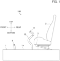
- FIG. 1 is a left side view illustrating a schematic configuration of a simulation control apparatus 100.
- the simulation control apparatus 100 is a simulation control apparatus for an aircraft, and used for, for example, simulation training of an aircraft using a VR space. That is, a pilot or a copilot as a trainee operates the simulation control apparatus 100 to thereby cause an aircraft to fly in a VR space.
- the simulation control apparatus 100 is used for simulation training of a helicopter.
- the simulation control apparatus 100 includes a chassis 1. In a space above the chassis 1, a pilot or a copilot as a trainee is seated on a seat 2 and operates an aircraft.
- the chassis 1 includes a top panel 1a on which the seat 2, a collective lever 3, ladder pedals 4, and a control stick 10 are located.
- the collective lever 3, the ladder pedals 4, and the control stick 10 are examples of operating members.
- a top-bottom direction, a front-rear direction, and a left-right direction of the trainee seated on the seat 2 will be hereinafter referred to as a top-bottom direction, a front-rear direction, and a left-right direction, respectively, for convenience of description.
- the collective lever 3 is located at the left of the seat 2.
- the collective lever 3 is used for causing the aircraft to ascend or descend or controlling the speed of the aircraft by pulling up or pushing down operation of the trainee such as the pilot. That is, with the pulling up or pushing down operation of the collective lever 3, the collective lever 3 rotates about a rotation shaft located below the collective lever 3, and using displacement of this rotation as a control input value, the aircraft ascends or descends or the speed of the aircraft changes.
- the control stick 10 is located forward of the seat 2 and between the feet of the trainee such as the pilot.
- the control stick 10 is also called a cyclic stick, and enables tilting operation in two-axis directions of the front-rear direction and the left-right direction.
- the control stick 10 is used for raising or lowering the nose of the aircraft to cause the aircraft to ascend and descend with the tilting operation by the trainee such as the pilot in the front-rear direction. That is, when the control stick 10 is tilted in the front-rear direction, the rotation shaft for the front-rear direction located below the control stick 10 rotates, and using displacement of this rotation as a control input value, the aircraft performs a pitching motion.
- the control stick 10 is also used for tilting the aircraft to the left or to the right with the tilting operation by the trainee such as the pilot in the left-right direction. That is, when the control stick 10 is tilted in the left-right direction, the rotation shaft for the left-right direction located below the control stick 10 rotates, and using displacement of this rotation as a control input value, the aircraft performs a rolling motion.
- the ladder pedals 4 are located at the feet of the trainee such as the pilot, and one of the pedals 4 corresponds to the left foot and the other corresponds to the right foot.
- the ladder pedals 4 allow the aircraft to perform a yawing motion to the left or to the right when being stepped with the feet of the trainee such as the pilot. That is, with rotation operation of the ladder pedals 4, the aircraft performs a yawing motion.
- the collective lever 3, the ladder pedals 4, and the control stick 10 are rotatable about a predetermined axis in both directions by operation of the trainee such as the pilot.
- FIG. 2 is a schematic view of the control stick 10 of the simulation control apparatus 100 and a peripheral portion thereof seen from the rear.
- FIG. 3 is a cross-sectional view taken along line A-A in FIG. 2 .
- FIG. 4 is a cross-sectional view taken along line B-B in FIG. 2 .
- FIG. 5 is a cross-sectional view taken along line C-C in FIG. 2 .
- the simulation control apparatus 100 includes the collective lever 3, the ladder pedals 4, and the control stick 10 described above, and also includes reaction force generators 20 and neutral position changers 30 associated with each of the rotation shafts of the collective lever 3, the ladder pedals 4, and the control stick 10.
- the reaction force generators 20 have substantially the same basic structure
- the neutral position changers 30 have substantially the same basic structure. Description of this example is directed to the reaction force generator 20 and the neutral position changer 30 associated with the control stick 10.
- the reaction force generators 20 and the neutral position changers 30 associated with the control stick 10 are used in two sets, one of which is for tilting operation in the front-rear direction and the other is for tilting operation in the left-right direction.
- reaction force generator 20 and the neutral position changer 30 for the tilting operation of the control stick 10 in the front-rear direction will be described.
- one rotation shaft is used for each of the collective lever 3 and the ladder pedals 4
- one reaction force generator 20 and one neutral position changer 30 are also associated with each of the collective lever 3 and the ladder pedals 4.
- a portion of the control stick 10, the reaction force generator 20, and the neutral position changer 30 are housed in the chassis 1. The same holds for the reaction force generators 20 and the neutral position changers 30 associated with the collective lever 3 and the ladder pedals 4.
- the control stick 10 is rotatable about an axis X1 in both directions.
- the control stick 10 are a shaft extending in the top-bottom direction. More specifically, the control stick 10 penetrates the top panel 1a and extends in the inside and outside of the chassis 1.
- the axis X1 is an example of a first axis.
- a shaft 12 having the axis X1 is located in a lower end potion of the control stick 10. Specifically, the shaft 12 extends in the left-right direction. The shaft 12 penetrates the lower end portion of the control stick 10 and is fixed to the control stick 10. That is, the control stick 10 is non-rotatable with respect to the shaft 12. In this manner, the control stick 10 is rotatable about the axis X1 in both directions together with the shaft 12. That is, the control stick 10 and the shaft 12 are rotatable about the axis X1 in the front-rear direction.
- the shaft 12 is rotatably supported by a bearing or other components.
- the control stick 10 includes an operation switch 11.
- the operation switch 11 is used for allowing the trainee such as the pilot to instruct predetermined change operation to the neutral position changer 30 described later.
- the reaction force generator 20 generates an operating reaction force when the trainee such as the pilot operates the control stick 10 and, when the trainee such as the pilot releases his/her hand from the control stick 10, causes the control stick 10 to return to a position at which the control stick 10 naturally stops, that is, to a neutral state.
- the neutral state in the case described for the state of each structure refers to a state where both a first arm 23 and a second arm 24 described later are in contact with a transferer 22, as illustrated in FIGS. 2 through 5 .
- the state where both the first arm 23 and the second arm 24 are in contact with the transferer 22 will be hereinafter referred to as a neutral state.
- the reaction force generator 20 includes a tension spring 26 that is deformed by rotation of the control stick 10 and generates an operating reaction force of the control stick 10.
- the reaction force generator 20 also includes the transferer 22, the first arm 23, and the second arm 24.
- the transferer 22 is connected to the control stick 10 and rotates together with the control stick 10.
- the transferer 22 transfers rotation of the stick 10 to the first arm 23 or the second arm 24.
- the transferer 22 is a rod that extends in the same direction as the shaft 12, that is, in the left-right direction.
- a cross section orthogonal to the axis of the transferer 22 has a circular shape.
- the reaction force generator 20 also includes a connector 21 that connects the transferer 22 to the shaft 12.
- the connector 21 is a rod extending in the top-bottom direction.
- the connector 21 has an upper end, which is one end, connected to one end of the shaft 12, and a lower end, which is the other end, connected to one end of the transferer 22. More specifically, the shaft 12 and the transferer 22 are connected to extend in opposite ways in the left-right direction from the connector 21. In this example, as illustrated in FIG.
- the shaft 12 is connected to extend rightward from the connector 21, and the transferer 22 is connected to extend leftward from the connector 21. That is, the connector 21 is located between the shaft 12 and the transferer 22 in the direction in which the shaft 12 and the transferer 22 extend.
- the transferer 22 and the shaft 12 are connected to each other through the connector 21 so that the transferer 22 is thereby connected to the control stick 10 through the connector 21 and the shaft 12. Accordingly, the transferer 22 rotates together with the control stick 10 in both directions about the axis X1. More specifically, the transferer 22 turns about the axis X1 as a turning center with rotation of the control stick 10.
- the first arm 23 When rotation of the control stick 10 in one way is transferred to the first arm 23 through the transferer 22, the first arm 23 thereby rotates about an axis X2 extending in the same direction as the axis X1 and deforms the tension spring 26.
- the second arm 24 When rotation of the control stick 10 in the other way is transferred to the second arm 24 through the transferer 22, the second arm 24 thereby rotates about the axis X2 extending in the same direction as the axis X1 and deforms the tension spring 26.
- the axis X2 corresponds to a second axis and a third axis. That is, in this example, the second axis and the third axis are the common axis X2.
- the first arm 23 and the second arm 24 will be hereinafter simply referred to as the arms 23 and 24, when these arms are not particularly distinguished.
- the first arm 23 and the second arm 24 are members each extending in the top-bottom direction.
- the first arm 23 and the second arm 24 are arranged side by side in the left-right direction.
- Each of the first arm 23 and the second arm 24 has an inverted L-shape when seen in the left-right direction.
- the first arm 23 and the second arm 24 overlap each other in the left-right direction in first ends 23a and 24a that are upper ends thereof, that is, portions corresponding to the horizontal bars of the L-shapes.
- the first arm 23 and the second arm 24 do not overlap each other in the left-right direction in portions other than the first ends 23a and 24a, that is, portions corresponding to the vertical bars of the L-shapes.
- the first arm 23 and the second arm 24 are arranged such that portions other than the first ends 23a and 24a are located adjacent to each other in the rotation directions thereof.
- the rotation directions are the front-rear direction.
- the first arm 23 and the second arm 24 are rotatable about the axis X2.
- one common shaft 25 having the axis X2 is located in the first ends 23a and 24a of the first arm 23 and the second arm 24.
- the shaft 25 is a member extending in the left-right direction.
- the shaft 25 penetrates the first ends 23a and 24a of the arms 23 and 24.
- the arms 23 and 24 are rotatable about the shaft 25. That is, the first arm 23 and the second arm 24 are rotatable in the front-rear direction.
- the axis X2 is coaxial with the axis X1.
- Each of the first arm 23 and the second arm 24 includes two recesses.
- the first arm 23 includes a first recess 23c and a second recess 23d
- the second arm 24 includes a first recess 24c and a second recess 24d.
- the first recesses 23c and 24c and the second recesses 23d and 24d are located on opposite surfaces that face each other in the front-rear direction in portions other than the first ends 23a and 24a of the first arm 23 and the second arm 24.
- the first recesses 23c and 24c and the second recesses 23d and 24d are located in this order from above in the arms 23 and 24.
- the second recesses 23d and 24d are located below the first recesses 23c and 24c.
- the first recess 23c of the first arm 23 and the first recess 24c of the second arm 24 face each other in the front-rear direction
- the second recess 23d of the first arm 23 and the second recess 24d of the second arm 24 face each other in the front-rear direction.
- Each of the first recesses 23c and 24c is, for example, semicircular when seen in the left-right direction.
- the first recesses 23c and 24c are shaped such that the outer periphery of the transferer 22 is fitted in the first recesses 23c and 24c in the neutral state.
- each of the first recesses 23c and 24c has a semicircular shape.
- the cross-sectional shape orthogonal to the axis of the transferer 22 is a rectangle
- each of the first recesses 23c and 24c also has a rectangular shape.
- the first arm 23 and the second arm 24 receive rotation of the control stick 10 through the transferer 22 and rotate.
- the transferer 22 rotates about the axis X1 in the same rotation direction as the control stick 10
- the rotation of the transferer 22 causes the first arm 23 to rotate about the axis X2.
- the transferer 22 rotates about the axis X1 in the same rotation direction as the control stick 10
- the rotation of the transferer 22 causes the second arm 24 to rotate about the axis X2.
- Each of the second recesses 23d and 24d is, for example, semicircular when seen in the left-right direction.
- the second recesses 23d and 24d are shaped such that a restrictor 34 of the neutral position changer 30 described later is fitted in the second recesses 23d and 24d in the neutral state illustrated in FIG. 5 .
- the tension spring 26 is an example of an elastic structure, and is a coil spring.
- the tension spring 26 is connected to the first arm 23 and the second arm 24. More specifically, the tension spring 26 is connected to the first arm 23 and the second arm 24 through fittings 27. A first end 26a of the tension spring 26 is connected to the first arm 23 through the fitting 27. A second end 26b of the tension spring 26 is connected to the second arm 24 through the fittings 27.
- each of the fittings 27 includes a first member 27a, a second member 27b, and an adjuster 27c.
- the first member 27a extends in the front-rear direction orthogonal to the top-bottom direction in which the arms 23 and 24 extend.
- the first members 27a are so-called cantilever rods attached to the arms 23 and 24 to extend from the arms 23 and 24 to the outer sides in the front-rear direction.
- the second member 27b is a rod extending in the sane top-bottom direction as the arms 23 and 24, and has one end connected to an outer end of the first member 27a and the other end connected to the adjuster 27c.
- the other end of the second member 27b has a screw hole penetrating in the front-rear direction, and the adjuster 27c is screwed into this screw hole.
- the adjuster 27c is connected to the first end 26a and the second end 26b of the tension spring 26.
- the adjuster 27c adjusts the overall length of the tension spring 26 in the neutral state, and is an adjusting screw, for example.
- the neutral state is a state where the transferer 22 is fitted in both the first recesses 23c and 24c of the first arm 23 and the second arm 24.
- the tension spring 26 is connected to the first arm 23 and the second arm 24 so that the first arm 23 and the second arm 24 thereby deforms the tension spring 26 when being rotated by the transferer 22.
- the first arm 23 is rotated by the transferer 22
- the first end 26a of the tension spring 26 is pulled, and the tension spring 26 extends.
- the second arm 24 is biased to rotate in a direction toward the first arm 23 by an elastic force of the tension spring 26, but does not rotate because of restriction of rotation by the restrictor 34 described later.
- FIG. 7 when the second arm 24 is rotated by the transferer 22, the second end 26b of the tension spring 26 is pulled, and the tension spring 26 extends.
- the first arm 23 is biased to rotate in a direction toward the second arm 24 by an elastic force of the tension spring 26, but does not rotate because of restriction of rotation by the restrictor 34 described later.
- the trainee such as the pilot releases his/her hand from the control stick 10 or loosen the grip
- the first arm 23 and the second arm 24 approach each other by an elastic force of the tension spring 26 to be in the neutral state.
- the first end 26a and the second end 26b of the tension spring 26 are connected outside the arms 23 and 24.
- the tension spring 26 has a sufficient length.
- the tension spring 26 is attached to the first member 27a and the second member 27b as rods without increase in size of the arms 23 and 24, increase in weight of the reaction force generator 20 can be suppressed.
- the first end 26a and the second end 26b of the tension spring 26 have hook shapes, and when the first end 26a and the second end 26b are hooked on an opening in the adjuster 27c, the tension spring 26 is connected to the adjuster 27c.
- a desired operating reaction force can be easily obtained by replacing the tension springs 26.
- An elastic force of the elongated tension spring 26 acts on the control stick 10 as an operating reaction force through the arms 23 and 24 and the transferer 22. In this manner, the tension spring 26 is deformed by rotation of the control stick 10 and generates an operating reaction force of the control stick 10.
- the first arm 23 and the second arm 24 are biased to approach each other by the tension spring 26. More specifically, in a state where the first arm 23 and the second arm 24 are closest to each other, that is, the overall length of the tension spring 26 is shortest, the tension spring 26 has a predetermined biasing force, that is, elastic force. That is, the overall length of the tension spring 26 in the neutral state is set to be larger than an equilibrium length.
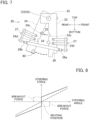
- FIG. 8 is a graph showing an operating force gradient.
- An operating angle is a rotation angle at or from the neutral position of the control stick 10, for example, and an operating force is a force for operating the control stick 10, for example, and corresponds to an operating reaction force.
- An operating force gradient indicated by the dotted line in FIG. 8 is an operating force gradient in a case where the overall length of the tension spring in the neutral state is set at an equilibrium length
- an operating force gradient indicated by the solid line in FIG. 8 is an operating force gradient in a case where the overall length of the tension spring 26 in the neutral state is set to be larger than the equilibrium length. As shown in FIG.
- a breakout force that is, a predetermined biasing force in the neutral position
- a breakout force can be obtained as compared to the case where the overall length of the tension spring in the neutral state is set at the equilibrium length.
- the predetermined biasing force of the tension spring 26 in the neutral state is adjusted by adjusting the overall length of the tension spring 26 with the adjuster 27c.
- the adjuster 27c is an example of an adjuster that adjusts the predetermined elastic force of the tension spring 26.
- the adjuster 27c that is an adjusting screw is screwed into the screw hole.
- the first arm 23, the second arm 24, and the transferer 22 are rotatable about the axis X2 as one unit.
- the neutral position changer 30 performs a trim adjustment of the aircraft.
- the trim adjustment is to adjust the neutral position of the control stick 10 to enable the trainee such as the pilot to control the aircraft for stable flight.
- a position of the control stick 10 in a trim state where all the external forces such as an aerodynamic force and an engine output exerted on the aircraft are balanced by trim adjustment will be referred to as a neutral position. While the control stick 10 is at the neutral position, an operating force of the control stick 10 is zero.
- the neutral position changer 30 includes the restrictor 34 located between the first arm 23 and the second arm 24.
- the restrictor 34 restricts rotation of the first arm 23 and the second arm 24 in the direction in which the first arm 23 and the second arm 24 approach each other so that when the first arm 23 or the second arm 24 is rotated by the transferer 22, a biasing force of the tension spring 26 is thereby exerted on the control stick 10.
- the neutral position changer 30 also changes the neutral position of the control stick 10 by rotationally moving the restrictor 34 about the axis X3.
- the neutral position changer 30 includes a brake 31, a shaft 32, a connector 33, and the restrictor 34.
- the shaft 32 has the axis X3 and is rotatable about the axis X3.
- the axis X3 is coaxial with the axis X2, and corresponds to a fourth axis.
- the shaft 32 is a member extending in the left-right direction.
- the restrictor 34 is a rod that extends in the same direction as the shaft 32, that is, in the left-right direction.
- a cross section orthogonal to the axis of the restrictor 34 has a circular shape, but may have other shapes such as a rectangle.
- the connector 33 connects the shaft 32 and the restrictor 34 to each other.
- the connector 33 is a rod extending in the top-bottom direction.
- the connector 33 has an upper end, which is one end, connected to one end of the shaft 32, and a lower end, which is the other end, connected to one end of the restrictor 34.
- the shaft 32 and the restrictor 34 are connected to extend in opposite ways in the left-right direction from the connector 33.
- the shaft 32 is connected to extend leftward from the connector 33
- the restrictor 34 is connected to extend rightward from the connector 33. That is, the connector 33 is located between the shaft 32 and the restrictor 34 in the direction in which the shaft 32 and the restrictor 34 extend.
- the thus-configured restrictor 34 is rotatable about the axis X3 together with the shaft 32 and the connector 33. More specifically, the restrictor 34 is turnable about the axis X3 as a turning center.
- the shaft 32 is coupled to the brake 31.
- the brake 31 is, for example, an electromagnetic brake.
- the brake 31 is switchable between a braking state of braking rotation operation of the shaft 32 and a releasing state of releasing rotation operation of the shaft 32.
- rotation operation of the restrictor 34 is braked, as illustrated in FIGS. 6 and 7 .
- the restrictor 34 Accordingly, with rotation of the control stick 10, one of the first arm 23 and the second arm 24 rotates, and rotation of the other is restricted by the restrictor 34 fitted in the second recesses 23d and 24d. Accordingly, the tension spring 26 is deformed to generate an operating reaction force.
- the restrictor 34 When the brake 31 becomes a releasing state, the restrictor 34 becomes a non-restriction state and becomes rotatable about the axis X3.
- the rotation of the restrictor 34 about the axis X3 changes the neutral position of the control stick 10. That is, the neutral position changer 30 switches the brake 31 to the releasing state to release rotation operation of the shaft 32 so that the restrictor 34 thereby moves about the axis X3.
- the brake 31 is switched to the releasing state.
- the first arm 23 is rotated about the axis X2 by the transferer 22.
- the restrictor 34 is in the non-restriction state, the second arm 24 is pulled toward the first arm 23 by an elastic force F of the tension spring 26 and rotates about the axis X2 together with the restrictor 34. That is, the second arm 24 is rotated by the elastic force F of the tension spring 26, and the restrictor 34 is rotated about the axis X3 by rotation of the second arm 24.
- the brake 31 is switched to the releasing state, in the reaction force generator 20, the first arm 23, the second arm 24, the transferer 22, and the tension spring 26 can rotate about the axis X2 as one unit.
- the simulation control apparatus 100 further includes an approach state detection sensor 40 that detects whether the control stick 10 is in a neutral state or not based on an approach state of the first arm 23 and the second arm 24, such as the distance, an angle, or a contact state between the first arm 23 and the second arm 24.
- the approach state detection sensor 40 may be any sensor that can detect an approach state of the first arm 23 and the second arm 24.
- the approach state detection sensor 40 is a position detection sensor, and included in one of the first arm 23 and the second arm 24.
- the approach state detection sensor 40 is included in the second arm 24. More specifically, the approach state detection sensor 40 is attached to a second end 24b that is a lower end of the second arm 24.
- the position detection sensor is, for example, a contact type sensor, and detects a contact state when the sensor contacts the second end 23b of the first arm 23. This detection can determine whether the control stick 10 is in the neutral state or not.
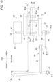
- FIG. 10 is a schematic view illustrating the ladder pedal 4 of the simulation control apparatus 100 and a peripheral portion thereof seen from the left.
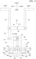
- FIG. 11 is a cross-sectional view taken along line A-A in FIG. 10 .
- FIG. 12 illustrates an example of operation of the reaction force generator 20 and corresponds to FIG. 11 .
- a connection state between the ladder pedal 4, and the reaction force generator 20 and the neutral position changer 30 associated with the ladder pedal 4 will be described.
- the rotation shaft of the ladder pedal 4 and the connector 21 of the reaction force generator 20 are connected to each other through a link mechanism 42.
- aspects different from the case of the control stick 10 described above will be described.
- these pedals are referred to as a left pedal 4A and a right pedal 4B, respectively.
- the ladder pedal 4 is rotatable about axis X1 in both directions.
- the shaft 41 having the axis X1 is located at the lower end of each of the left pedal 4A and the right pedal 4B.
- the shaft 41 is a member extending in the left-right direction.
- the shafts 41 of the left pedal 4A and the right pedal 4B are coaxial.
- the shafts 41 are fixed to the left pedal 4A and the right pedal 4B. That is, the ladder pedal 4 is non-rotatable with respect to the shaft 41. In this manner, the ladder pedal 4 rotates about the axis X1 in the front-rear direction together with the shaft 41.
- each link mechanism 42 includes a first link 43, a second link 44, a third link 46, a fourth link 47, and two shafts 45 and 48.
- Two first links 43 are used for the left pedal 4A and the right pedal 4B.
- Each of the first links 43 is a member extending in the front-rear direction.
- the two first links 43 are rotatably coupled at one end to the left pedal 4A and the right pedal 4B.
- the two first links 43 are rotatably coupled at the other end to both ends the second links 44.
- the second links 44 are members each extending in the left-right direction.
- the shaft 45 having an axis X11 is located at the center of each second link 44.
- the second link 44 is rotatable about the axis X11, that is, rotatable with respect to the shaft 45.
- the shaft 45 is a member extending in the top-bottom direction.
- the third link 46 is a member extending in the front-rear direction.
- One end of the third link 46 is rotatably coupled to one end of the second link 44.
- one end of the third link 46 is coupled to an end of the second link 44 to which the first link 43 for the left pedal 4A is coupled.
- the other end of the third link 46 is rotatably coupled to the fourth link 47.
- the fourth link 47 is a member extending in the left-right direction.
- the shaft 48 having an axis X12 is located at an end of the fourth link 47 opposite to the third link 46.
- the shaft 48 is a member extending in the top-bottom direction. The shaft 48 penetrates the fourth link 47 and is fixed to the fourth link 47.
- the fourth link 47 rotates about the axis X12 together with the shaft 48.
- One end of the shaft 48 is fixed to the connector 21 of the reaction force generator 20.
- the axis X12 is coaxial with the axis X2 of the arms 23 and 24. That is, in the case of the ladder pedals 4, unlike the case of the control stick 10 described above, the axis X1 is perpendicular to the axis X2.
- the connector 21 has one end connected to the shaft 48 and the other end connected to the transferer 22. More specifically, the shaft 48 and the transferer 22 are connected to extend from the connector 21 in opposite ways in the top-bottom direction. In this example, as illustrated in FIG. 10 , the shaft 48 is connected to extend downward from the connector 21, and the transferer 22 is connected to extend upward from the connector 21. That is, the connector 21 is located between the shaft 48 and the transferer 22 in the direction in which the shaft 48 and the transferer 22 extend. The shaft 48, the connector 21, and the transferer 22 rotate about the axis X12 as one unit.
- the shaft 41 as the rotation shaft of the ladder pedals 4 and the connector 21 of the reaction force generator 20 are connected to each other through the link mechanism 42.
- the transferer 22 turns with rotation of the ladder pedals 4 as operating members about the axis X1. More specifically, the transferer 22 turns about the axis X12 as a turning center. For example, as illustrated in FIG. 12 , when the right pedal 4B is pressed, the second link 44 rotates about the axis X11, and accordingly, the connector 21 and the transferer 22 rotate about the axis X12. In this manner, the second arm 24 rotates about the axis X2, for example.
- the flight simulation control apparatus 100 includes the control stick 10 that rotates about the first axis (axis X1) in both directions, and the reaction force generator 20 including the tension spring 26 that is deformed by rotation of the control stick 10 and generates an operating reaction force of the control stick 10.
- the reaction force generator 20 also includes the transferer 22 that is connected to the control stick 10 and rotates together with the control stick 10, the first arm 23 that rotates about the second axis (axis X2) and deforms the tension spring 26 when rotation of the control stick 10 in one direction is transferred to the first arm 23 through the transferer 22, and the second arm 24 that rotates about the third axis (axis X2) extending in the same direction as the second axis (axis X2) and deforms the tension spring 26 when rotation of the control stick 10 in another direction is transferred to the second arm 24 through the transferer 22.
- the transferer 22 that is connected to the control stick 10 and rotates together with the control stick 10, the first arm 23 that rotates about the second axis (axis X2) and deforms the tension spring 26 when rotation of the control stick 10 in one direction is transferred to the first arm 23 through the transferer 22, and the second arm 24 that rotates about the third axis (axis X2) extending in the same direction as the second axis (axis
- the reaction force generator 20 transfers rotation of the operating member such as the control stick 10 by the transferer 22 to cause the first arm 23 and the second arm 24 to rotate so that the tension spring 26 is thereby deformed to generate an operating reaction force.
- the reaction force generator 20 transfers rotation of the operating member such as the control stick 10 by the transferer 22 to cause the first arm 23 and the second arm 24 to rotate so that the tension spring 26 is thereby deformed to generate an operating reaction force.
- operation space for the first arm 23, the second arm 24, and other components necessary for generating an operating reaction force can be reduced.
- the size of the reaction force generator 20, and further the size of the simulation control apparatus 100 can be reduced.
- the first arm 23 and the second arm 24 are located adjacent to each other in rotation directions thereof, and are biased by the tension spring 26 in directions in which the first arm 23 and the second arm 24 approach each other.
- the simulation control apparatus 100 further includes the neutral position changer 30 that includes the restrictor 34 that is located between the first arm 23 and the second arm 24 and restricts rotation of the first arm 23 and the second arm 24 in the directions in which the first arm 23 and the second arm 24 approach each other.
- the neutral position changer 30 changes the neutral position of the control stick 10 or other components by rotating the transferer 22, the first arm 23, and the second arm 24 together about the first axis, the second axis, and the third axis through rotational movement of the restrictor 34 about the fourth axis (axis X3) extending in the identical direction to the second axis (axis X2).
- the second axis and the third axis are the common axis (axis X2).
- the first axis (axis X1) and the axis (axis X2) common to the first axis are coaxial.
- size reduction includes operation space necessary for the transferer 22 connected to the control stick 10, and thus, the size of the simulation control apparatus can be further reduced.
- the flight simulation control apparatus 100 further includes the approach state detection sensor 40 that detects a neutral state in which the first arm 23 and the second arm 24 are closest to each other, based on an approach state of the first arm 23 and the second arm 24.
- the approach state detection sensor 40 can be easily attached to a position where the first arm 23 and the second arm 24 approach each other, for example.
- the neutral position can be easily detected. Since the approach state detection sensor 40 is easily attached, the approach state detection sensor 40 is easily replaced.
- the tension spring 26 is connected between the first arm 23 and the second arm 24 to generate a predetermined elastic force in the neutral state.
- the control stick 10 in the neutral position is not easily displaced by a slight external force such as vibrations.
- the neutral position of the control stick 10 can be held with stability.
- the reaction force generator 20 further includes the adjuster 27c that adjusts the predetermined elastic force of the tension spring 26.
- a breakout force can be adjusted by adjusting the predetermined elastic force of the tension spring 26.
- an appropriate breakout force in accordance with situations of simulation training.
- the simulation control apparatus 100 is also applicable as a simulation control apparatus for an aircraft other than a helicopter.
- the simulation control apparatus 100 is applicable to a simulation control apparatus for a mobile object other than the aircraft.
- the elastic structure is one tension spring 26 connected to the first arm 23 and the second arm 24 in the above example, the technique disclosed here is not limited to this example.
- the elastic structure may be a compression spring located outside each of the first arm 23 and the second arm 24.
- the approach state detection sensor 40 is not limited to the position detection sensor and may be a non-contact sensor, for example.
- a distance sensor such as a laser is used, for example, and may be located at a position other than the lower ends of the arms 23 and 24 or at a position other than the arms 23 and 24.
- the second axis and the third axis are the common axis, that is, the axis X2, in the above example, but may be different axes.
- the axis X2 as the common axis and the axis X1 as the first axis may not be coaxial.
- Multiple adjusters 27c may be located in the top-bottom direction. By adjusting the adjusters 27c connecting the first end 26a and the second end 26b of the tension spring 26, an operating force gradient can be changed without replacing the tension spring 26 itself.
- the operating force gradient may be changed by including screw holes in the second member 27b and changing the screw holes in which the adjusters 27c are screwed.
- the device 10 may further include a mechanism that changes the lengths of the arms 23 and 24, the direction from the axis X1 to the axis of the transferer 22 in the top-bottom direction, and the distance from the axis X3 to the axis of the restrictor 34 in the top-bottom direction. By changing the lengths and the distances, the operating force gradient can be changed without replacing the tension spring 26 itself.
- the reaction force generator 20 or the neutral position changer 30 is also applicable to an operating member that has a rotation shaft and preferably generates an operating reaction force or performs trim adjustment, other than the collective lever 3, the ladder pedals 4, and the control stick 10.
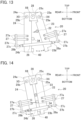
- FIG. 13 illustrates a schematic configuration of a reaction force generator 20 according to another embodiment.
- FIG. 14 illustrates operation of changing a neutral position according to another embodiment and corresponds to FIG. 13 .
- a rotation center at rotation with the neutral position held is different from a rotation center at rotation in changing the neutral position.
- Each of the two arms 23 and 24 has a rotation center at rotation with the neutral position held.
- the first arm 23 is rotatable about an axis X4
- the second arm 24 is rotatable about an axis X5 different from the axis X4.
- a shaft 25a having the axis X4 is located at a first end 23a of the first arm 23, and a shaft 25b having the axis X5 is located at a first end 24a of the second arm 24.
- the axis X4 is an example of a second axis
- the axis X5 is an example of a third axis.
- the reaction force generator 20 of this variation includes a base 28 coupling the first arm 23 and the second arm 24.
- the base 28 is a member extending in the front-rear direction, and the first arm 23 and the second arm 24 are respectively coupled to both ends of the base 28.
- the shafts 25a and 25b are respectively located at both ends of the base 28.
- the shafts 25a and 25b may be fixed to the base 28 or may be rotatable with respect to the base 28.
- the base 28 is rotatable about an axis X6 different from the axes X4 and X5.
- a shaft 25c having the axis X6 is located at the center of the base 28. In this configuration, when the base 28 rotates about the axis X6, the two arms 23 and 24 also rotate about the axis X6.
- the restrictor 34 becomes a non-restriction state to be rotatable.
- the neutral position of the control stick 10 is changed accordingly.
- the restrictor 34 becomes the non-restriction state, and thus, the first arm 23 is biased to rotate about the axis X4 by the transferer 22, whereas the second arm 24 is pulled toward the first arm 23 by an elastic force of the tension spring 26 and is biased to rotate about the axis X5, for example. That is, both the first arm 23 and the second arm 24 are biased to rotate together. Then, as illustrated in FIG.
- Two pairs of the simulation control apparatuss 100 of the embodiment may be prepared and placed side by side in the left-right direction. In this case, both a pilot and a copilot can perform simulation training at the same time.
Landscapes
- Engineering & Computer Science (AREA)
- Theoretical Computer Science (AREA)
- Physics & Mathematics (AREA)
- General Physics & Mathematics (AREA)
- Aviation & Aerospace Engineering (AREA)
- Business, Economics & Management (AREA)
- Educational Administration (AREA)
- Educational Technology (AREA)
- Automation & Control Theory (AREA)
- Mechanical Control Devices (AREA)
Abstract
Description
- The technique disclosed here relates to a flight simulation control apparatus.
- Aircraft piloting devices with mechanisms that generate piloting reaction forces of control sticks or other devices to obtain a sense of piloting have been known to date. A piloting device disclosed in
Patent Document 1 includes a cylinder housing a compression spring, and a rod inserted into the cylinder to be movable forward and backward. In this piloting device, rotation of a control stick causes the rod to move forward and backward from the cylinder so that the compression spring is deformed. An elastic force of the deformed compression spring acts on the control stick as an operating reaction force. - Patent Document 1:
Japanese Patent Application Publication No. 10-59293 - In the case of constructing the simulation control apparatus described above as a simulation control apparatus for simulation training, the simulation control apparatus is preferably compact as a whole. The piloting device described above, however, still has room for improvement in terms of miniaturization.
- It is therefore an object of the technique disclosed here to reduce the size of a simulation control apparatus for an aircraft.
- A flight simulation control apparatus disclosed here includes: an operating member that rotates about a first axis in both directions; and a reaction force generator including an elastic structure that is deformed by rotation of the operating member and generates an operating reaction force of the operating member. The reaction force generator further includes a transferer, a first arm, and a second arm. The transferer is connected to the operating member and rotates together with the operating member. The first arm rotates about a second axis and deforms the elastic structure when rotation of the operating member in one direction is transferred to the first arm through the transferer. The second arm rotates about a third axis extending in an identical direction to the second axis and deforms the elastic structure when rotation of the operating member in another direction is transferred to the second arm through the transferer.
- The flight simulation control apparatus described above can be downsized.
-
- [
FIG. 1] FIG. 1 is a left side view illustrating a schematic configuration of a simulation control apparatus. - [
FIG. 2] FIG. 2 is a schematic view illustrating a control stick of the simulation control apparatus and a peripheral portion thereof seen from the rear. - [
FIG. 3] FIG. 3 is a cross-sectional view taken along line A-A inFIG. 2 . - [
FIG. 4] FIG. 4 is a cross-sectional view taken along line B-B inFIG. 2 . - [
FIG. 5] FIG. 5 is a cross-sectional view taken along line C-C inFIG. 2 . - [
FIG. 6] FIG. 6 illustrates an example of operation of a reaction force generator and corresponds toFIG. 5 . - [
FIG. 7] FIG. 7 illustrates an example of operation of the reaction force generator and corresponds toFIG. 5 . - [
FIG. 8] FIG. 8 is a graph showing an operating force gradient. - [
FIG. 9] FIG. 9 illustrates an example of operation of changing a neutral position and corresponds toFIG. 5 . - [
FIG. 10] FIG. 10 is a schematic view illustrating a ladder pedal of the simulation control apparatus and a peripheral portion thereof seen from the left. - [
FIG. 11] FIG. 11 is a cross-sectional view taken along line A-A inFIG. 10 . - [
FIG. 12] FIG. 12 illustrates an example of operation of the reaction force generator and corresponds toFIG. 11 . - [
FIG. 13] FIG. 13 illustrates a schematic configuration of a reaction force generator according to another embodiment. - [
FIG. 14] FIG. 14 illustrates operation of changing a neutral position according to another embodiment and corresponds toFIG. 13 . - An exemplary embodiment will be specifically described hereinafter with reference to the drawings.
FIG. 1 is a left side view illustrating a schematic configuration of asimulation control apparatus 100. - The
simulation control apparatus 100 according to this embodiment is a simulation control apparatus for an aircraft, and used for, for example, simulation training of an aircraft using a VR space. That is, a pilot or a copilot as a trainee operates thesimulation control apparatus 100 to thereby cause an aircraft to fly in a VR space. In this embodiment, thesimulation control apparatus 100 is used for simulation training of a helicopter. - As illustrated in
FIG. 1 , thesimulation control apparatus 100 includes achassis 1. In a space above thechassis 1, a pilot or a copilot as a trainee is seated on aseat 2 and operates an aircraft. Thechassis 1 includes atop panel 1a on which theseat 2, a collective lever 3,ladder pedals 4, and acontrol stick 10 are located. The collective lever 3, theladder pedals 4, and thecontrol stick 10 are examples of operating members. In this embodiment, a top-bottom direction, a front-rear direction, and a left-right direction of the trainee seated on theseat 2 will be hereinafter referred to as a top-bottom direction, a front-rear direction, and a left-right direction, respectively, for convenience of description. - As an example, the collective lever 3 is located at the left of the
seat 2. The collective lever 3 is used for causing the aircraft to ascend or descend or controlling the speed of the aircraft by pulling up or pushing down operation of the trainee such as the pilot. That is, with the pulling up or pushing down operation of the collective lever 3, the collective lever 3 rotates about a rotation shaft located below the collective lever 3, and using displacement of this rotation as a control input value, the aircraft ascends or descends or the speed of the aircraft changes. - The
control stick 10 is located forward of theseat 2 and between the feet of the trainee such as the pilot. Thecontrol stick 10 is also called a cyclic stick, and enables tilting operation in two-axis directions of the front-rear direction and the left-right direction. Thecontrol stick 10 is used for raising or lowering the nose of the aircraft to cause the aircraft to ascend and descend with the tilting operation by the trainee such as the pilot in the front-rear direction. That is, when thecontrol stick 10 is tilted in the front-rear direction, the rotation shaft for the front-rear direction located below thecontrol stick 10 rotates, and using displacement of this rotation as a control input value, the aircraft performs a pitching motion. Thecontrol stick 10 is also used for tilting the aircraft to the left or to the right with the tilting operation by the trainee such as the pilot in the left-right direction. That is, when thecontrol stick 10 is tilted in the left-right direction, the rotation shaft for the left-right direction located below thecontrol stick 10 rotates, and using displacement of this rotation as a control input value, the aircraft performs a rolling motion. - The
ladder pedals 4 are located at the feet of the trainee such as the pilot, and one of thepedals 4 corresponds to the left foot and the other corresponds to the right foot. Theladder pedals 4 allow the aircraft to perform a yawing motion to the left or to the right when being stepped with the feet of the trainee such as the pilot. That is, with rotation operation of theladder pedals 4, the aircraft performs a yawing motion. - In this manner, the collective lever 3, the
ladder pedals 4, and thecontrol stick 10 are rotatable about a predetermined axis in both directions by operation of the trainee such as the pilot. -
FIG. 2 is a schematic view of thecontrol stick 10 of thesimulation control apparatus 100 and a peripheral portion thereof seen from the rear.FIG. 3 is a cross-sectional view taken along line A-A inFIG. 2 .FIG. 4 is a cross-sectional view taken along line B-B inFIG. 2 .FIG. 5 is a cross-sectional view taken along line C-C inFIG. 2 . - The
simulation control apparatus 100 includes the collective lever 3, theladder pedals 4, and thecontrol stick 10 described above, and also includesreaction force generators 20 andneutral position changers 30 associated with each of the rotation shafts of the collective lever 3, theladder pedals 4, and thecontrol stick 10. Thereaction force generators 20 have substantially the same basic structure, and theneutral position changers 30 have substantially the same basic structure. Description of this example is directed to thereaction force generator 20 and theneutral position changer 30 associated with thecontrol stick 10. Thereaction force generators 20 and theneutral position changers 30 associated with thecontrol stick 10 are used in two sets, one of which is for tilting operation in the front-rear direction and the other is for tilting operation in the left-right direction. In this example, thereaction force generator 20 and theneutral position changer 30 for the tilting operation of thecontrol stick 10 in the front-rear direction will be described. In this example, since one rotation shaft is used for each of the collective lever 3 and theladder pedals 4, onereaction force generator 20 and oneneutral position changer 30 are also associated with each of the collective lever 3 and theladder pedals 4. - A portion of the
control stick 10, thereaction force generator 20, and theneutral position changer 30 are housed in thechassis 1. The same holds for thereaction force generators 20 and theneutral position changers 30 associated with the collective lever 3 and theladder pedals 4. - The
control stick 10 is rotatable about an axis X1 in both directions. Thecontrol stick 10 are a shaft extending in the top-bottom direction. More specifically, thecontrol stick 10 penetrates thetop panel 1a and extends in the inside and outside of thechassis 1. The axis X1 is an example of a first axis. - A
shaft 12 having the axis X1 is located in a lower end potion of thecontrol stick 10. Specifically, theshaft 12 extends in the left-right direction. Theshaft 12 penetrates the lower end portion of thecontrol stick 10 and is fixed to thecontrol stick 10. That is, thecontrol stick 10 is non-rotatable with respect to theshaft 12. In this manner, thecontrol stick 10 is rotatable about the axis X1 in both directions together with theshaft 12. That is, thecontrol stick 10 and theshaft 12 are rotatable about the axis X1 in the front-rear direction. Theshaft 12 is rotatably supported by a bearing or other components. - As illustrated in
FIG. 1 , thecontrol stick 10 includes anoperation switch 11. Theoperation switch 11 is used for allowing the trainee such as the pilot to instruct predetermined change operation to theneutral position changer 30 described later. - The
reaction force generator 20 generates an operating reaction force when the trainee such as the pilot operates thecontrol stick 10 and, when the trainee such as the pilot releases his/her hand from thecontrol stick 10, causes thecontrol stick 10 to return to a position at which thecontrol stick 10 naturally stops, that is, to a neutral state. In this example, the neutral state in the case described for the state of each structure refers to a state where both afirst arm 23 and asecond arm 24 described later are in contact with atransferer 22, as illustrated inFIGS. 2 through 5 . The state where both thefirst arm 23 and thesecond arm 24 are in contact with thetransferer 22 will be hereinafter referred to as a neutral state. - As illustrated in
FIG. 5 , thereaction force generator 20 includes atension spring 26 that is deformed by rotation of thecontrol stick 10 and generates an operating reaction force of thecontrol stick 10. Thereaction force generator 20 also includes thetransferer 22, thefirst arm 23, and thesecond arm 24. - The
transferer 22 is connected to thecontrol stick 10 and rotates together with thecontrol stick 10. Thetransferer 22 transfers rotation of thestick 10 to thefirst arm 23 or thesecond arm 24. - Specifically, the
transferer 22 is a rod that extends in the same direction as theshaft 12, that is, in the left-right direction. In this example, a cross section orthogonal to the axis of thetransferer 22 has a circular shape. Thereaction force generator 20 also includes aconnector 21 that connects thetransferer 22 to theshaft 12. In this example, theconnector 21 is a rod extending in the top-bottom direction. Theconnector 21 has an upper end, which is one end, connected to one end of theshaft 12, and a lower end, which is the other end, connected to one end of thetransferer 22. More specifically, theshaft 12 and thetransferer 22 are connected to extend in opposite ways in the left-right direction from theconnector 21. In this example, as illustrated inFIG. 2 , theshaft 12 is connected to extend rightward from theconnector 21, and thetransferer 22 is connected to extend leftward from theconnector 21. That is, theconnector 21 is located between theshaft 12 and thetransferer 22 in the direction in which theshaft 12 and thetransferer 22 extend. - In this manner, the
transferer 22 and theshaft 12 are connected to each other through theconnector 21 so that thetransferer 22 is thereby connected to thecontrol stick 10 through theconnector 21 and theshaft 12. Accordingly, thetransferer 22 rotates together with thecontrol stick 10 in both directions about the axis X1. More specifically, thetransferer 22 turns about the axis X1 as a turning center with rotation of thecontrol stick 10. - When rotation of the
control stick 10 in one way is transferred to thefirst arm 23 through thetransferer 22, thefirst arm 23 thereby rotates about an axis X2 extending in the same direction as the axis X1 and deforms thetension spring 26. When rotation of thecontrol stick 10 in the other way is transferred to thesecond arm 24 through thetransferer 22, thesecond arm 24 thereby rotates about the axis X2 extending in the same direction as the axis X1 and deforms thetension spring 26. The axis X2 corresponds to a second axis and a third axis. That is, in this example, the second axis and the third axis are the common axis X2. Thefirst arm 23 and thesecond arm 24 will be hereinafter simply referred to as thearms - The
first arm 23 and thesecond arm 24 are members each extending in the top-bottom direction. Thefirst arm 23 and thesecond arm 24 are arranged side by side in the left-right direction. Each of thefirst arm 23 and thesecond arm 24 has an inverted L-shape when seen in the left-right direction. Thefirst arm 23 and thesecond arm 24 overlap each other in the left-right direction infirst ends first arm 23 and thesecond arm 24 do not overlap each other in the left-right direction in portions other than the first ends 23a and 24a, that is, portions corresponding to the vertical bars of the L-shapes. In other words, thefirst arm 23 and thesecond arm 24 are arranged such that portions other than the first ends 23a and 24a are located adjacent to each other in the rotation directions thereof. In this example, the rotation directions are the front-rear direction. - The
first arm 23 and thesecond arm 24 are rotatable about the axis X2. Specifically, onecommon shaft 25 having the axis X2 is located in the first ends 23a and 24a of thefirst arm 23 and thesecond arm 24. Specifically, theshaft 25 is a member extending in the left-right direction. Theshaft 25 penetrates the first ends 23a and 24a of thearms arms shaft 25. That is, thefirst arm 23 and thesecond arm 24 are rotatable in the front-rear direction. In this example, the axis X2 is coaxial with the axis X1. - Each of the
first arm 23 and thesecond arm 24 includes two recesses. Specifically, thefirst arm 23 includes afirst recess 23c and asecond recess 23d, and thesecond arm 24 includes afirst recess 24c and asecond recess 24d. The first recesses 23c and 24c and thesecond recesses first arm 23 and thesecond arm 24. The first recesses 23c and 24c and thesecond recesses arms second recesses first recesses first recess 23c of thefirst arm 23 and thefirst recess 24c of thesecond arm 24 face each other in the front-rear direction, and thesecond recess 23d of thefirst arm 23 and thesecond recess 24d of thesecond arm 24 face each other in the front-rear direction. - Each of the
first recesses transferer 22 is fitted in thefirst recesses transferer 22 has a circular shape, each of thefirst recesses transferer 22 is a rectangle, for example, each of thefirst recesses first arm 23 and thesecond arm 24 receive rotation of thecontrol stick 10 through thetransferer 22 and rotate. For example, when thecontrol stick 10 rotates rearward, as illustrated inFIG. 6 , thetransferer 22 rotates about the axis X1 in the same rotation direction as thecontrol stick 10, and the rotation of thetransferer 22 causes thefirst arm 23 to rotate about the axis X2. When thecontrol stick 10 rotates forward, as illustrated inFIG. 7 , thetransferer 22 rotates about the axis X1 in the same rotation direction as thecontrol stick 10, and the rotation of thetransferer 22 causes thesecond arm 24 to rotate about the axis X2. Each of thesecond recesses restrictor 34 of theneutral position changer 30 described later is fitted in thesecond recesses FIG. 5 . - The
tension spring 26 is an example of an elastic structure, and is a coil spring. Thetension spring 26 is connected to thefirst arm 23 and thesecond arm 24. More specifically, thetension spring 26 is connected to thefirst arm 23 and thesecond arm 24 throughfittings 27. Afirst end 26a of thetension spring 26 is connected to thefirst arm 23 through the fitting 27. Asecond end 26b of thetension spring 26 is connected to thesecond arm 24 through thefittings 27. - As illustrated in
FIG. 5 , in this example, each of thefittings 27 includes afirst member 27a, asecond member 27b, and anadjuster 27c. Thefirst member 27a extends in the front-rear direction orthogonal to the top-bottom direction in which thearms arms first recesses second recesses first members 27a are so-called cantilever rods attached to thearms arms second member 27b is a rod extending in the sane top-bottom direction as thearms first member 27a and the other end connected to theadjuster 27c. For example, the other end of thesecond member 27b has a screw hole penetrating in the front-rear direction, and theadjuster 27c is screwed into this screw hole. - The
adjuster 27c is connected to thefirst end 26a and thesecond end 26b of thetension spring 26. Theadjuster 27c adjusts the overall length of thetension spring 26 in the neutral state, and is an adjusting screw, for example. In other words, the neutral state is a state where thetransferer 22 is fitted in both thefirst recesses first arm 23 and thesecond arm 24. - In this manner, the
tension spring 26 is connected to thefirst arm 23 and thesecond arm 24 so that thefirst arm 23 and thesecond arm 24 thereby deforms thetension spring 26 when being rotated by thetransferer 22. For example, as illustrated inFIG. 6 , when thefirst arm 23 is rotated by thetransferer 22, thefirst end 26a of thetension spring 26 is pulled, and thetension spring 26 extends. At this time, thesecond arm 24 is biased to rotate in a direction toward thefirst arm 23 by an elastic force of thetension spring 26, but does not rotate because of restriction of rotation by the restrictor 34 described later. As illustrated inFIG. 7 , when thesecond arm 24 is rotated by thetransferer 22, thesecond end 26b of thetension spring 26 is pulled, and thetension spring 26 extends. At this time, thefirst arm 23 is biased to rotate in a direction toward thesecond arm 24 by an elastic force of thetension spring 26, but does not rotate because of restriction of rotation by the restrictor 34 described later. When the trainee such as the pilot releases his/her hand from thecontrol stick 10 or loosen the grip, thefirst arm 23 and thesecond arm 24 approach each other by an elastic force of thetension spring 26 to be in the neutral state. - In this example, as illustrated in
FIG. 5 , thefirst end 26a and thesecond end 26b of thetension spring 26 are connected outside thearms arms tension spring 26 has a sufficient length. Thus, it is possible to reduce plastic deformation of thetension spring 26 in a case where the rotation angles of thearms tension spring 26 is attached to thefirst member 27a and thesecond member 27b as rods without increase in size of thearms reaction force generator 20 can be suppressed. - In this example, as illustrated in
FIG. 5 , thefirst end 26a and thesecond end 26b of thetension spring 26 have hook shapes, and when thefirst end 26a and thesecond end 26b are hooked on an opening in theadjuster 27c, thetension spring 26 is connected to theadjuster 27c. A desired operating reaction force can be easily obtained by replacing the tension springs 26. - An elastic force of the
elongated tension spring 26 acts on thecontrol stick 10 as an operating reaction force through thearms transferer 22. In this manner, thetension spring 26 is deformed by rotation of thecontrol stick 10 and generates an operating reaction force of thecontrol stick 10. - In the manner described above, in the
reaction force generator 20, rotation of thecontrol stick 10 is transferred by thetransferer 22 to cause thefirst arm 23 and thesecond arm 24 to rotate so that thetension spring 26 is thereby deformed to generate an operating reaction force. Thus, as compared to a mechanism in which the rod is displaced in the axial direction thereof by rotation of the control stick to thereby deform the elastic structure and generate an operating reaction force, for example, operation space for thefirst arm 23, thesecond arm 24, and other components necessary for generating an operating reaction force is reduced. This reduces the size of thereaction force generator 20. - The
first arm 23 and thesecond arm 24 are biased to approach each other by thetension spring 26. More specifically, in a state where thefirst arm 23 and thesecond arm 24 are closest to each other, that is, the overall length of thetension spring 26 is shortest, thetension spring 26 has a predetermined biasing force, that is, elastic force. That is, the overall length of thetension spring 26 in the neutral state is set to be larger than an equilibrium length. -
FIG. 8 is a graph showing an operating force gradient. An operating angle is a rotation angle at or from the neutral position of thecontrol stick 10, for example, and an operating force is a force for operating thecontrol stick 10, for example, and corresponds to an operating reaction force. An operating force gradient indicated by the dotted line inFIG. 8 is an operating force gradient in a case where the overall length of the tension spring in the neutral state is set at an equilibrium length, and an operating force gradient indicated by the solid line inFIG. 8 is an operating force gradient in a case where the overall length of thetension spring 26 in the neutral state is set to be larger than the equilibrium length. As shown inFIG. 8 , in the case where the overall length of thetension spring 26 in the neutral state is larger than the equilibrium length, a breakout force, that is, a predetermined biasing force in the neutral position, can be obtained as compared to the case where the overall length of the tension spring in the neutral state is set at the equilibrium length. By obtaining a breakout force, even when the trainee such as the pilot unintentionally applies a minute force to thecontrol stick 10, the aircraft does not move and is stable in the neutral position. In addition, in the case of mounting an automatic piloting system such as an automatic flight control system (AFCS), an accurate neutral position needs to be detected, but when a breakout force is obtained, the neutral position can be definitely detected, and in addition, it is possible to make the trainee such as the pilot aware of the point to switch to manual operation. Accordingly, a state without a trim is maintained, and the aircraft can fly with stability. - The predetermined biasing force of the
tension spring 26 in the neutral state is adjusted by adjusting the overall length of thetension spring 26 with theadjuster 27c. That is, theadjuster 27c is an example of an adjuster that adjusts the predetermined elastic force of thetension spring 26. For example, when the overall length of thetension spring 26 is increased by theadjuster 27c, the predetermined biasing force increases. In this example, the other end of thesecond member 27b has a screw hole penetrating the end in the front-rear direction, and theadjuster 27c that is an adjusting screw is screwed into the screw hole. Thus, the overall length of thetension spring 26 can be increased or reduced by rotating theadjuster 27c. - In addition, in the
reaction force generator 20, thefirst arm 23, thesecond arm 24, and thetransferer 22 are rotatable about the axis X2 as one unit. - The
neutral position changer 30 performs a trim adjustment of the aircraft. The trim adjustment is to adjust the neutral position of thecontrol stick 10 to enable the trainee such as the pilot to control the aircraft for stable flight. In this example, a position of thecontrol stick 10 in a trim state where all the external forces such as an aerodynamic force and an engine output exerted on the aircraft are balanced by trim adjustment will be referred to as a neutral position. While thecontrol stick 10 is at the neutral position, an operating force of thecontrol stick 10 is zero. - The
neutral position changer 30 includes the restrictor 34 located between thefirst arm 23 and thesecond arm 24. The restrictor 34 restricts rotation of thefirst arm 23 and thesecond arm 24 in the direction in which thefirst arm 23 and thesecond arm 24 approach each other so that when thefirst arm 23 or thesecond arm 24 is rotated by thetransferer 22, a biasing force of thetension spring 26 is thereby exerted on thecontrol stick 10. Theneutral position changer 30 also changes the neutral position of thecontrol stick 10 by rotationally moving the restrictor 34 about the axis X3. - Specifically, the
neutral position changer 30 includes abrake 31, ashaft 32, aconnector 33, and therestrictor 34. - The
shaft 32 has the axis X3 and is rotatable about the axis X3. In this example, the axis X3 is coaxial with the axis X2, and corresponds to a fourth axis. Theshaft 32 is a member extending in the left-right direction. The restrictor 34 is a rod that extends in the same direction as theshaft 32, that is, in the left-right direction. In this example, a cross section orthogonal to the axis of the restrictor 34 has a circular shape, but may have other shapes such as a rectangle. Theconnector 33 connects theshaft 32 and the restrictor 34 to each other. In this example, theconnector 33 is a rod extending in the top-bottom direction. Theconnector 33 has an upper end, which is one end, connected to one end of theshaft 32, and a lower end, which is the other end, connected to one end of therestrictor 34. - More specifically, the
shaft 32 and the restrictor 34 are connected to extend in opposite ways in the left-right direction from theconnector 33. In this example, as illustrated inFIG. 2 , theshaft 32 is connected to extend leftward from theconnector 33, and the restrictor 34 is connected to extend rightward from theconnector 33. That is, theconnector 33 is located between theshaft 32 and the restrictor 34 in the direction in which theshaft 32 and the restrictor 34 extend. - The thus-configured
restrictor 34 is rotatable about the axis X3 together with theshaft 32 and theconnector 33. More specifically, therestrictor 34 is turnable about the axis X3 as a turning center. - The
shaft 32 is coupled to thebrake 31. Thebrake 31 is, for example, an electromagnetic brake. Thebrake 31 is switchable between a braking state of braking rotation operation of theshaft 32 and a releasing state of releasing rotation operation of theshaft 32. When thebrake 31 is switched to the braking state, rotation operation of the restrictor 34 is braked, as illustrated inFIGS. 6 and7 . Thus, in this state, rotation of thefirst arm 23 and thesecond arm 24 in the direction in which thefirst arm 23 and thesecond arm 24 approach each other is restricted by therestrictor 34. Accordingly, with rotation of thecontrol stick 10, one of thefirst arm 23 and thesecond arm 24 rotates, and rotation of the other is restricted by the restrictor 34 fitted in thesecond recesses tension spring 26 is deformed to generate an operating reaction force. - When the
brake 31 becomes a releasing state, therestrictor 34 becomes a non-restriction state and becomes rotatable about the axis X3. The rotation of the restrictor 34 about the axis X3 changes the neutral position of thecontrol stick 10. That is, theneutral position changer 30 switches thebrake 31 to the releasing state to release rotation operation of theshaft 32 so that the restrictor 34 thereby moves about the axis X3. - For example, in performing operation of rotating the
control stick 10 rearward, when theoperation switch 11 is pushed once, for example, thebrake 31 is switched to the releasing state. Then, as illustrated inFIG. 9 , thefirst arm 23 is rotated about the axis X2 by thetransferer 22. At this time, since the restrictor 34 is in the non-restriction state, thesecond arm 24 is pulled toward thefirst arm 23 by an elastic force F of thetension spring 26 and rotates about the axis X2 together with therestrictor 34. That is, thesecond arm 24 is rotated by the elastic force F of thetension spring 26, and the restrictor 34 is rotated about the axis X3 by rotation of thesecond arm 24. Further, when thebrake 31 is switched to the releasing state, in thereaction force generator 20, thefirst arm 23, thesecond arm 24, thetransferer 22, and thetension spring 26 can rotate about the axis X2 as one unit. - Then, when pushing of the
operation switch 11 is released, thebrake 31 is switched to the braking state. Then, rotation operation of the restrictor 34 is stopped, and the position of the restrictor 34 is fixed. The position of thecontrol stick 10 at this time is a new neutral position. In this manner, the neutral position of thecontrol stick 10 is changed. - The
simulation control apparatus 100 further includes an approachstate detection sensor 40 that detects whether thecontrol stick 10 is in a neutral state or not based on an approach state of thefirst arm 23 and thesecond arm 24, such as the distance, an angle, or a contact state between thefirst arm 23 and thesecond arm 24. The approachstate detection sensor 40 may be any sensor that can detect an approach state of thefirst arm 23 and thesecond arm 24. In this example, the approachstate detection sensor 40 is a position detection sensor, and included in one of thefirst arm 23 and thesecond arm 24. In this example, the approachstate detection sensor 40 is included in thesecond arm 24. More specifically, the approachstate detection sensor 40 is attached to asecond end 24b that is a lower end of thesecond arm 24. The position detection sensor is, for example, a contact type sensor, and detects a contact state when the sensor contacts thesecond end 23b of thefirst arm 23. This detection can determine whether thecontrol stick 10 is in the neutral state or not. -
FIG. 10 is a schematic view illustrating theladder pedal 4 of thesimulation control apparatus 100 and a peripheral portion thereof seen from the left.FIG. 11 is a cross-sectional view taken along line A-A inFIG. 10 .FIG. 12 illustrates an example of operation of thereaction force generator 20 and corresponds toFIG. 11 . - A connection state between the
ladder pedal 4, and thereaction force generator 20 and theneutral position changer 30 associated with theladder pedal 4 will be described. In the case of theladder pedal 4, unlike thecontrol stick 10 and the collective lever 3 as other operating members, the rotation shaft of theladder pedal 4 and theconnector 21 of thereaction force generator 20 are connected to each other through alink mechanism 42. In this example, aspects different from the case of thecontrol stick 10 described above will be described. In the following description, when theladder pedal 4 for the left foot and theladder pedal 4 for the right foot are distinguished, these pedals are referred to as aleft pedal 4A and aright pedal 4B, respectively. - In a manner similar to the
control stick 10, theladder pedal 4 is rotatable about axis X1 in both directions. Theshaft 41 having the axis X1 is located at the lower end of each of theleft pedal 4A and theright pedal 4B. Theshaft 41 is a member extending in the left-right direction. Theshafts 41 of theleft pedal 4A and theright pedal 4B are coaxial. Theshafts 41 are fixed to theleft pedal 4A and theright pedal 4B. That is, theladder pedal 4 is non-rotatable with respect to theshaft 41. In this manner, theladder pedal 4 rotates about the axis X1 in the front-rear direction together with theshaft 41. - In this example, each
link mechanism 42 includes afirst link 43, asecond link 44, athird link 46, afourth link 47, and twoshafts first links 43 are used for theleft pedal 4A and theright pedal 4B. Each of thefirst links 43 is a member extending in the front-rear direction. The twofirst links 43 are rotatably coupled at one end to theleft pedal 4A and theright pedal 4B. The twofirst links 43 are rotatably coupled at the other end to both ends thesecond links 44. Thesecond links 44 are members each extending in the left-right direction. Theshaft 45 having an axis X11 is located at the center of eachsecond link 44. Thesecond link 44 is rotatable about the axis X11, that is, rotatable with respect to theshaft 45. Theshaft 45 is a member extending in the top-bottom direction. - The
third link 46 is a member extending in the front-rear direction. One end of thethird link 46 is rotatably coupled to one end of thesecond link 44. In this example, one end of thethird link 46 is coupled to an end of thesecond link 44 to which thefirst link 43 for theleft pedal 4A is coupled. The other end of thethird link 46 is rotatably coupled to thefourth link 47. Thefourth link 47 is a member extending in the left-right direction. Theshaft 48 having an axis X12 is located at an end of thefourth link 47 opposite to thethird link 46. Theshaft 48 is a member extending in the top-bottom direction. Theshaft 48 penetrates thefourth link 47 and is fixed to thefourth link 47. Thefourth link 47 rotates about the axis X12 together with theshaft 48. One end of theshaft 48 is fixed to theconnector 21 of thereaction force generator 20. In this example, the axis X12 is coaxial with the axis X2 of thearms ladder pedals 4, unlike the case of thecontrol stick 10 described above, the axis X1 is perpendicular to the axis X2. - The
connector 21 has one end connected to theshaft 48 and the other end connected to thetransferer 22. More specifically, theshaft 48 and thetransferer 22 are connected to extend from theconnector 21 in opposite ways in the top-bottom direction. In this example, as illustrated inFIG. 10 , theshaft 48 is connected to extend downward from theconnector 21, and thetransferer 22 is connected to extend upward from theconnector 21. That is, theconnector 21 is located between theshaft 48 and thetransferer 22 in the direction in which theshaft 48 and thetransferer 22 extend. Theshaft 48, theconnector 21, and thetransferer 22 rotate about the axis X12 as one unit. - In this manner, the
shaft 41 as the rotation shaft of theladder pedals 4 and theconnector 21 of thereaction force generator 20 are connected to each other through thelink mechanism 42. In this manner, in the case of theladder pedals 4, in a manner similar to the case of thecontrol stick 10 described above, thetransferer 22 turns with rotation of theladder pedals 4 as operating members about the axis X1. More specifically, thetransferer 22 turns about the axis X12 as a turning center. For example, as illustrated inFIG. 12 , when theright pedal 4B is pressed, thesecond link 44 rotates about the axis X11, and accordingly, theconnector 21 and thetransferer 22 rotate about the axis X12. In this manner, thesecond arm 24 rotates about the axis X2, for example. In the manner described above, in the case of theladder pedals 4 in which the axis X1 is perpendicular to the axis X2, rotation of theladder pedals 4 is transferred by thetransferer 22 so that thearms reaction force generator 20 and theneutral position changer 30 of theladder pedals 4 are similar to those of thecontrol stick 10 described above. - As described above, the flight
simulation control apparatus 100 includes thecontrol stick 10 that rotates about the first axis (axis X1) in both directions, and thereaction force generator 20 including thetension spring 26 that is deformed by rotation of thecontrol stick 10 and generates an operating reaction force of thecontrol stick 10. Thereaction force generator 20 also includes thetransferer 22 that is connected to thecontrol stick 10 and rotates together with thecontrol stick 10, thefirst arm 23 that rotates about the second axis (axis X2) and deforms thetension spring 26 when rotation of thecontrol stick 10 in one direction is transferred to thefirst arm 23 through thetransferer 22, and thesecond arm 24 that rotates about the third axis (axis X2) extending in the same direction as the second axis (axis X2) and deforms thetension spring 26 when rotation of thecontrol stick 10 in another direction is transferred to thesecond arm 24 through thetransferer 22. - With this configuration, the
reaction force generator 20 transfers rotation of the operating member such as thecontrol stick 10 by thetransferer 22 to cause thefirst arm 23 and thesecond arm 24 to rotate so that thetension spring 26 is thereby deformed to generate an operating reaction force. Thus, as compared to a mechanism in which the rod is displaced in the axial direction thereof by rotation of the control stick to thereby deform the elastic structure and generate an operating reaction force, for example, operation space for thefirst arm 23, thesecond arm 24, and other components necessary for generating an operating reaction force can be reduced. As a result, the size of thereaction force generator 20, and further the size of thesimulation control apparatus 100, can be reduced. - In the
reaction force generator 20 of the flightsimulation control apparatus 100, thefirst arm 23 and thesecond arm 24 are located adjacent to each other in rotation directions thereof, and are biased by thetension spring 26 in directions in which thefirst arm 23 and thesecond arm 24 approach each other. Thesimulation control apparatus 100 further includes theneutral position changer 30 that includes the restrictor 34 that is located between thefirst arm 23 and thesecond arm 24 and restricts rotation of thefirst arm 23 and thesecond arm 24 in the directions in which thefirst arm 23 and thesecond arm 24 approach each other. Theneutral position changer 30 changes the neutral position of thecontrol stick 10 or other components by rotating thetransferer 22, thefirst arm 23, and thesecond arm 24 together about the first axis, the second axis, and the third axis through rotational movement of the restrictor 34 about the fourth axis (axis X3) extending in the identical direction to the second axis (axis X2). - With this configuration, when one of the
first arm 23 and thesecond arm 24 is rotated by thetransferer 22, rotation of the other is restricted by therestrictor 34. Thus, thetension spring 26 is reliably deformed to generate an operating reaction force. Since the neutral position of thecontrol stick 10 is changed by rotationally moving the restrictor 34, the neutral position can be easily changed. In addition, since the configuration rotationally operates the restrictor 34, operation space for theneutral position changer 30 necessary for changing the neutral position is reduced. Accordingly, the size of theneutral position changer 30, and further thesimulation control apparatus 100, can be reduced. - In the flight
simulation control apparatus 100, the second axis and the third axis are the common axis (axis X2). - With this configuration, operation space necessary for the
first arm 23 and thesecond arm 24 can be further reduced. Accordingly, the size of the simulation control apparatus can be further reduced. In addition, the number of parts of thereaction force generator 20 can be reduced. - In the flight
simulation control apparatus 100, the first axis (axis X1) and the axis (axis X2) common to the first axis are coaxial. - With this configuration, size reduction includes operation space necessary for the
transferer 22 connected to thecontrol stick 10, and thus, the size of the simulation control apparatus can be further reduced. - The flight
simulation control apparatus 100 further includes the approachstate detection sensor 40 that detects a neutral state in which thefirst arm 23 and thesecond arm 24 are closest to each other, based on an approach state of thefirst arm 23 and thesecond arm 24. - With this configuration, since any sensor may be used so long as it detects the neutral position based on the approach state of the
first arm 23 and thesecond arm 24, the approachstate detection sensor 40 can be easily attached to a position where thefirst arm 23 and thesecond arm 24 approach each other, for example. In addition, since the neutral state is detected by detecting approach of the first andsecond arms state detection sensor 40 is easily attached, the approachstate detection sensor 40 is easily replaced. - In the
simulation control apparatus 100, thetension spring 26 is connected between thefirst arm 23 and thesecond arm 24 to generate a predetermined elastic force in the neutral state. - With this configuration, since the
tension spring 26 has a predetermined elastic force in the neutral state in which thefirst arm 23 and thesecond arm 24 are closest to each other, a breakout force can be obtained. By obtaining the breakout force, an operating reaction force can be obtained from start of operation from the neutral position of thecontrol stick 10. Thus, an operating sense closer to an actual sense can be obtained in simulation training. - Since a breakout force is obtained, the
control stick 10 in the neutral position is not easily displaced by a slight external force such as vibrations. Thus, the neutral position of thecontrol stick 10 can be held with stability. - In the flight
simulation control apparatus 100, thereaction force generator 20 further includes theadjuster 27c that adjusts the predetermined elastic force of thetension spring 26. - With this configuration, a breakout force can be adjusted by adjusting the predetermined elastic force of the
tension spring 26. Thus, an appropriate breakout force in accordance with situations of simulation training. - In the foregoing section, the embodiment has been described as an example of the technique disclosed in the present application. The technique disclosed here, however, is not limited to this embodiment, and is applicable to other embodiments obtained by changes, replacements, additions, and/or omissions as necessary. Components described in the above embodiment may be combined as a new embodiment. Components provided in the accompanying drawings and the detailed description can include components unnecessary for solving problems as well as components necessary for solving problems in order to exemplify the technique. Therefore, it should not be concluded that such unnecessary components are necessary only because these unnecessary components are included in the accompanying drawings or the detailed description.
- For example, the
simulation control apparatus 100 is also applicable as a simulation control apparatus for an aircraft other than a helicopter. Thesimulation control apparatus 100 is applicable to a simulation control apparatus for a mobile object other than the aircraft. - Although the elastic structure is one
tension spring 26 connected to thefirst arm 23 and thesecond arm 24 in the above example, the technique disclosed here is not limited to this example. For example, the elastic structure may be a compression spring located outside each of thefirst arm 23 and thesecond arm 24. - The approach
state detection sensor 40 is not limited to the position detection sensor and may be a non-contact sensor, for example. As the non-contact sensor, a distance sensor such as a laser is used, for example, and may be located at a position other than the lower ends of thearms arms - The second axis and the third axis are the common axis, that is, the axis X2, in the above example, but may be different axes. The axis X2 as the common axis and the axis X1 as the first axis may not be coaxial.
-
Multiple adjusters 27c may be located in the top-bottom direction. By adjusting theadjusters 27c connecting thefirst end 26a and thesecond end 26b of thetension spring 26, an operating force gradient can be changed without replacing thetension spring 26 itself. - The operating force gradient may be changed by including screw holes in the
second member 27b and changing the screw holes in which theadjusters 27c are screwed. - The
device 10 may further include a mechanism that changes the lengths of thearms transferer 22 in the top-bottom direction, and the distance from the axis X3 to the axis of the restrictor 34 in the top-bottom direction. By changing the lengths and the distances, the operating force gradient can be changed without replacing thetension spring 26 itself. - The
reaction force generator 20 or theneutral position changer 30 is also applicable to an operating member that has a rotation shaft and preferably generates an operating reaction force or performs trim adjustment, other than the collective lever 3, theladder pedals 4, and thecontrol stick 10. - In the
reaction force generator 20, the configurations of thearms FIG. 13 illustrates a schematic configuration of areaction force generator 20 according to another embodiment.FIG. 14 illustrates operation of changing a neutral position according to another embodiment and corresponds toFIG. 13 . - In two
arms arms FIG. 13 , thefirst arm 23 is rotatable about an axis X4, and thesecond arm 24 is rotatable about an axis X5 different from the axis X4. Ashaft 25a having the axis X4 is located at afirst end 23a of thefirst arm 23, and ashaft 25b having the axis X5 is located at afirst end 24a of thesecond arm 24. In this variation, the axis X4 is an example of a second axis, and the axis X5 is an example of a third axis. - The
reaction force generator 20 of this variation includes a base 28 coupling thefirst arm 23 and thesecond arm 24. Thebase 28 is a member extending in the front-rear direction, and thefirst arm 23 and thesecond arm 24 are respectively coupled to both ends of thebase 28. Specifically, theshafts base 28. Theshafts base 28. Thebase 28 is rotatable about an axis X6 different from the axes X4 and X5. Ashaft 25c having the axis X6 is located at the center of thebase 28. In this configuration, when thebase 28 rotates about the axis X6, the twoarms - In the thus-configured
reaction force generator 20, as illustrated inFIG. 13 , while abrake 31 is in a braking state, atransferer 22 rotates with rotation of thecontrol stick 10, and accordingly, thefirst arm 23, for example, rotates about the axis X4. Accordingly, thetension spring 26 is deformed to generate an operating reaction force. At this time, rotation of thesecond arm 24 toward thefirst arm 23, that is, rotation of thesecond arm 24 about the axis X5, is restricted by therestrictor 34. - When the
brake 31 becomes a releasing state, therestrictor 34 becomes a non-restriction state to be rotatable. When the restrictor 34 rotates, the neutral position of thecontrol stick 10 is changed accordingly. When thebrake 31 is switched to the releasing state in rotating thecontrol stick 10, therestrictor 34 becomes the non-restriction state, and thus, thefirst arm 23 is biased to rotate about the axis X4 by thetransferer 22, whereas thesecond arm 24 is pulled toward thefirst arm 23 by an elastic force of thetension spring 26 and is biased to rotate about the axis X5, for example. That is, both thefirst arm 23 and thesecond arm 24 are biased to rotate together. Then, as illustrated inFIG. 14 , since thefirst arm 23 and thesecond arm 24 cannot rotate about the axis X4 and the axis X5, respectively, thefirst arm 23 and thesecond arm 24 rotate about the axis X6 together with thebase 28. Then, in a manner similar to the embodiment described above, thebrake 31 is switched to the braking state so that the position of the restrictor 34 is thereby fixed. In this manner, the neutral position of thecontrol stick 10 is changed. Other configurations, effects, and advantages are similar to those of the embodiment. - Two pairs of the
simulation control apparatuss 100 of the embodiment may be prepared and placed side by side in the left-right direction. In this case, both a pilot and a copilot can perform simulation training at the same time.
Claims (7)
- A flight simulation control apparatus comprising:an operating member that rotates about a first axis in both directions; anda reaction force generator including an elastic structure that is deformed by rotation of the operating member and generates an operating reaction force of the operating member, whereinthe reaction force generator further includesa transferer that is connected to the operating member and rotates together with the operating member,a first arm that rotates about a second axis and deforms the elastic structure when rotation of the operating member in one direction is transferred to the first arm through the transferer, anda second arm that rotates about a third axis extending in an identical direction to the second axis and deforms the elastic structure when rotation of the operating member in another direction is transferred to the second arm through the transferer.
- The flight simulation control apparatus according to claim 1, whereinin the reaction force generator, the first arm and the second arm are located adjacent to each other in rotation directions thereof, and are biased by the elastic structure in directions in which the first arm and the second arm approach each other,the flight simulation control apparatus further includes a neutral position changer that includes a restrictor that is located between the first arm and the second arm and restricts rotation of the first arm and the second arm in the directions in which the first arm and the second arm approach each other, andthe neutral position changer changes a neutral position of the operating member by rotating the transferer, the first arm, and the second arm together about the first axis, the second axis, and the third axis through rotational movement of the restrictor about a fourth axis extending in an identical direction to the second axis.
- The flight simulation control apparatus according to claim 1 or 2, wherein
the second axis and the third axis are a common axis. - The flight simulation control apparatus according to claim 3, wherein
the first axis and the common axis are coaxial. - The flight simulation control apparatus according to claim 2, further comprising
an approach state detection sensor that detects a neutral state in which the first arm and the second arm are closest to each other, based on an approach state of the first arm and the second arm. - The flight simulation control apparatus according to claim 2, wherein
the elastic structure is connected between the first arm and the second arm to generate a predetermined elastic force in the neutral state. - The flight simulation control apparatus according to claim 6, wherein
the reaction force generator further includes an adjuster that adjusts the predetermined elastic force of the elastic structure.
Applications Claiming Priority (2)
| Application Number | Priority Date | Filing Date | Title |
|---|---|---|---|
| JP2021215248 | 2021-12-28 | ||
| PCT/JP2022/048630 WO2023127957A1 (en) | 2021-12-28 | 2022-12-28 | Simulator for aircract |
Publications (3)
| Publication Number | Publication Date |
|---|---|
| EP4459600A1 true EP4459600A1 (en) | 2024-11-06 |
| EP4459600A4 EP4459600A4 (en) | 2025-04-30 |
| EP4459600B1 EP4459600B1 (en) | 2026-01-28 |
Family
ID=86999234
Family Applications (1)
| Application Number | Title | Priority Date | Filing Date |
|---|---|---|---|
| EP22916179.9A Active EP4459600B1 (en) | 2021-12-28 | 2022-12-28 | Simulator for aircraft |
Country Status (4)
| Country | Link |
|---|---|
| US (1) | US20240355222A1 (en) |
| EP (1) | EP4459600B1 (en) |
| JP (1) | JP7752703B2 (en) |
| WO (1) | WO2023127957A1 (en) |
Family Cites Families (10)
| Publication number | Priority date | Publication date | Assignee | Title |
|---|---|---|---|---|
| GB611560A (en) * | 1945-06-27 | 1948-11-01 | Link Aviat Devices Inc | Simulated flight control loading and centering means for grounded aviation trainer |
| JPH07111664B2 (en) * | 1992-03-18 | 1995-11-29 | 川崎重工業株式会社 | Feeling mechanism of joystick type controller for aircraft |
| US5727188A (en) * | 1993-05-10 | 1998-03-10 | Hayes; Charles L. | Flight-control simulator for computer games |
| JP2948153B2 (en) | 1996-08-27 | 1999-09-13 | 株式会社コミュータヘリコプタ先進技術研究所 | Pilot device |
| JP2002014736A (en) | 2000-06-30 | 2002-01-18 | Namco Ltd | Operation reaction force applying device |
| FR2872306B1 (en) | 2004-06-29 | 2006-09-22 | Sagem | DEVICE FOR REMOTELY CONTROLLING GOVERNMENTS OF AN AIRCRAFT |
| FR2954980B1 (en) * | 2010-01-04 | 2012-02-10 | Guillemot Corp | JOYSTICK WITH COMPENSATION SPRINGS, MANUFACTURING METHOD AND CORRESPONDING LEVER. |
| KR20170060904A (en) * | 2015-11-25 | 2017-06-02 | 주식회사 바로텍시너지 | Aircraft simulator having automatic position adjustable stick |
| US10724632B1 (en) * | 2017-11-27 | 2020-07-28 | Parker-Hannifin Corporation | Return to neutral mechanism for hydrostatic transmission |
| JP7463212B2 (en) * | 2020-06-26 | 2024-04-08 | 川崎重工業株式会社 | Aircraft control simulator |
-
2022
- 2022-12-28 JP JP2023571104A patent/JP7752703B2/en active Active
- 2022-12-28 WO PCT/JP2022/048630 patent/WO2023127957A1/en not_active Ceased
- 2022-12-28 EP EP22916179.9A patent/EP4459600B1/en active Active
-
2024
- 2024-06-28 US US18/758,083 patent/US20240355222A1/en active Pending
Also Published As
| Publication number | Publication date |
|---|---|
| EP4459600A4 (en) | 2025-04-30 |
| WO2023127957A1 (en) | 2023-07-06 |
| EP4459600B1 (en) | 2026-01-28 |
| US20240355222A1 (en) | 2024-10-24 |
| JPWO2023127957A1 (en) | 2023-07-06 |
| JP7752703B2 (en) | 2025-10-10 |
Similar Documents
| Publication | Publication Date | Title |
|---|---|---|
| RU2593185C1 (en) | Inceptor of complex dynamic control of air and ground vehicle | |
| US6128554A (en) | Device for actuating a controlled member for an aircraft, particularly such as a fly-by-wire helicopter | |
| CA2804801C (en) | Pilot control system with adjustable pedals | |
| EP2259967B1 (en) | Pedal operated apparatus for controlling an aircraft nose wheel steering system | |
| US9051836B2 (en) | Pilot control system with compact gimbal mechanism | |
| JP5868057B2 (en) | Active control column with manual switching to passive control column | |
| EP2626297A1 (en) | Integrated aircraft flight control units | |
| EP3560823B1 (en) | Optimized pitch and roll control apparatus for an aircraft | |
| EP1918195A1 (en) | Rudder pedal assembly with non-parallel slide rails | |
| EP2626300B1 (en) | Pilot control system with hand rest | |
| US20120234985A1 (en) | Cyclic stick for mechanically transmitting commands for controlling a rotorcraft, the stick having a lever arm that is amplified selectively in the event of an emergency | |
| CA2804332C (en) | Pilot control system with pendent grip | |
| EP4459600B1 (en) | Simulator for aircraft | |
| US20140353433A1 (en) | Rotorcraft flight control stick tiltably mounted on a support by a flexible rod with a fixed end | |
| US20230126079A1 (en) | Flight simulation control apparatus | |
| CN117944872A (en) | Pedal mechanism | |
| JP4813038B2 (en) | Boarding object tilting device | |
| CN120440263A (en) | Aircraft control panel trim equipment | |
| RU2652284C1 (en) | Aircraft manual control device | |
| CN217724472U (en) | A body-building apparatus that is used for body-building apparatus's swing arm mechanism and has it | |
| US20220244722A1 (en) | Flight stick cockpit simulator ground station systems | |
| JP2019089508A (en) | Electric actuator device | |
| CN113593358A (en) | Two-degree-of-freedom VR airship driving simulation system | |
| KR20260051504A (en) | Reconfigurable control input device for uam aircrfat simulation cockpit system | |
| RU2652372C1 (en) | Main rotor brake stick |
Legal Events
| Date | Code | Title | Description |
|---|---|---|---|
| STAA | Information on the status of an ep patent application or granted ep patent |
Free format text: STATUS: THE INTERNATIONAL PUBLICATION HAS BEEN MADE |
|
| PUAI | Public reference made under article 153(3) epc to a published international application that has entered the european phase |
Free format text: ORIGINAL CODE: 0009012 |
|
| STAA | Information on the status of an ep patent application or granted ep patent |
Free format text: STATUS: REQUEST FOR EXAMINATION WAS MADE |
|
| 17P | Request for examination filed |
Effective date: 20240722 |
|
| AK | Designated contracting states |
Kind code of ref document: A1 Designated state(s): AL AT BE BG CH CY CZ DE DK EE ES FI FR GB GR HR HU IE IS IT LI LT LU LV MC ME MK MT NL NO PL PT RO RS SE SI SK SM TR |
|
| REG | Reference to a national code |
Ref country code: DE Ref legal event code: R079 Free format text: PREVIOUS MAIN CLASS: G09B0009280000 Ipc: G09B0009120000 Ref document number: 602022029564 Country of ref document: DE |
|
| DAV | Request for validation of the european patent (deleted) | ||
| DAX | Request for extension of the european patent (deleted) | ||
| A4 | Supplementary search report drawn up and despatched |
Effective date: 20250401 |
|
| RIC1 | Information provided on ipc code assigned before grant |
Ipc: G05G 5/03 20080401ALI20250326BHEP Ipc: G09B 9/46 20060101ALI20250326BHEP Ipc: G09B 9/28 20060101ALI20250326BHEP Ipc: G09B 9/16 20060101ALI20250326BHEP Ipc: G09B 9/12 20060101AFI20250326BHEP |
|
| GRAP | Despatch of communication of intention to grant a patent |
Free format text: ORIGINAL CODE: EPIDOSNIGR1 |
|
| STAA | Information on the status of an ep patent application or granted ep patent |
Free format text: STATUS: GRANT OF PATENT IS INTENDED |
|
| GRAJ | Information related to disapproval of communication of intention to grant by the applicant or resumption of examination proceedings by the epo deleted |
Free format text: ORIGINAL CODE: EPIDOSDIGR1 |
|
| STAA | Information on the status of an ep patent application or granted ep patent |
Free format text: STATUS: REQUEST FOR EXAMINATION WAS MADE |
|
| GRAP | Despatch of communication of intention to grant a patent |
Free format text: ORIGINAL CODE: EPIDOSNIGR1 |
|
| STAA | Information on the status of an ep patent application or granted ep patent |
Free format text: STATUS: GRANT OF PATENT IS INTENDED |
|
| INTG | Intention to grant announced |
Effective date: 20250901 |
|
| INTC | Intention to grant announced (deleted) | ||
| INTG | Intention to grant announced |
Effective date: 20250915 |
|
| GRAS | Grant fee paid |
Free format text: ORIGINAL CODE: EPIDOSNIGR3 |
|
| GRAA | (expected) grant |
Free format text: ORIGINAL CODE: 0009210 |
|
| STAA | Information on the status of an ep patent application or granted ep patent |
Free format text: STATUS: THE PATENT HAS BEEN GRANTED |
|
| AK | Designated contracting states |
Kind code of ref document: B1 Designated state(s): AL AT BE BG CH CY CZ DE DK EE ES FI FR GB GR HR HU IE IS IT LI LT LU LV MC ME MK MT NL NO PL PT RO RS SE SI SK SM TR |
|
| REG | Reference to a national code |
Ref country code: CH Ref legal event code: F10 Free format text: ST27 STATUS EVENT CODE: U-0-0-F10-F00 (AS PROVIDED BY THE NATIONAL OFFICE) Effective date: 20260128 Ref country code: GB Ref legal event code: FG4D |
|
| REG | Reference to a national code |
Ref country code: DE Ref legal event code: R096 Ref document number: 602022029564 Country of ref document: DE |
|
| REG | Reference to a national code |
Ref country code: CH Ref legal event code: R17 Free format text: ST27 STATUS EVENT CODE: U-0-0-R10-R17 (AS PROVIDED BY THE NATIONAL OFFICE) Effective date: 20260223 |
|
| REG | Reference to a national code |
Ref country code: IE Ref legal event code: FG4D |
|
| REG | Reference to a national code |
Ref country code: NL Ref legal event code: MP Effective date: 20260128 |
|
| PG25 | Lapsed in a contracting state [announced via postgrant information from national office to epo] |
Ref country code: NL Free format text: LAPSE BECAUSE OF FAILURE TO SUBMIT A TRANSLATION OF THE DESCRIPTION OR TO PAY THE FEE WITHIN THE PRESCRIBED TIME-LIMIT Effective date: 20260128 |
|
| REG | Reference to a national code |
Ref country code: AT Ref legal event code: MK05 Ref document number: 1882524 Country of ref document: AT Kind code of ref document: T Effective date: 20260128 |
|
| PG25 | Lapsed in a contracting state [announced via postgrant information from national office to epo] |
Ref country code: RS Free format text: LAPSE BECAUSE OF FAILURE TO SUBMIT A TRANSLATION OF THE DESCRIPTION OR TO PAY THE FEE WITHIN THE PRESCRIBED TIME-LIMIT Effective date: 20260428 |
|
| PG25 | Lapsed in a contracting state [announced via postgrant information from national office to epo] |
Ref country code: ES Free format text: LAPSE BECAUSE OF FAILURE TO SUBMIT A TRANSLATION OF THE DESCRIPTION OR TO PAY THE FEE WITHIN THE PRESCRIBED TIME-LIMIT Effective date: 20260128 |
|
| PG25 | Lapsed in a contracting state [announced via postgrant information from national office to epo] |
Ref country code: PL Free format text: LAPSE BECAUSE OF FAILURE TO SUBMIT A TRANSLATION OF THE DESCRIPTION OR TO PAY THE FEE WITHIN THE PRESCRIBED TIME-LIMIT Effective date: 20260128 |
|
| PG25 | Lapsed in a contracting state [announced via postgrant information from national office to epo] |
Ref country code: GR Free format text: LAPSE BECAUSE OF FAILURE TO SUBMIT A TRANSLATION OF THE DESCRIPTION OR TO PAY THE FEE WITHIN THE PRESCRIBED TIME-LIMIT Effective date: 20260429 |
|
| REG | Reference to a national code |
Ref country code: LT Ref legal event code: MG9D |
|
| PG25 | Lapsed in a contracting state [announced via postgrant information from national office to epo] |
Ref country code: LT Free format text: LAPSE BECAUSE OF FAILURE TO SUBMIT A TRANSLATION OF THE DESCRIPTION OR TO PAY THE FEE WITHIN THE PRESCRIBED TIME-LIMIT Effective date: 20260128 |
|
| PG25 | Lapsed in a contracting state [announced via postgrant information from national office to epo] |
Ref country code: NO Free format text: LAPSE BECAUSE OF FAILURE TO SUBMIT A TRANSLATION OF THE DESCRIPTION OR TO PAY THE FEE WITHIN THE PRESCRIBED TIME-LIMIT Effective date: 20260428 |
|
| PG25 | Lapsed in a contracting state [announced via postgrant information from national office to epo] |
Ref country code: FI Free format text: LAPSE BECAUSE OF FAILURE TO SUBMIT A TRANSLATION OF THE DESCRIPTION OR TO PAY THE FEE WITHIN THE PRESCRIBED TIME-LIMIT Effective date: 20260128 Ref country code: SE Free format text: LAPSE BECAUSE OF FAILURE TO SUBMIT A TRANSLATION OF THE DESCRIPTION OR TO PAY THE FEE WITHIN THE PRESCRIBED TIME-LIMIT Effective date: 20260128 Ref country code: AT Free format text: LAPSE BECAUSE OF FAILURE TO SUBMIT A TRANSLATION OF THE DESCRIPTION OR TO PAY THE FEE WITHIN THE PRESCRIBED TIME-LIMIT Effective date: 20260128 |
|
| PG25 | Lapsed in a contracting state [announced via postgrant information from national office to epo] |
Ref country code: HR Free format text: LAPSE BECAUSE OF FAILURE TO SUBMIT A TRANSLATION OF THE DESCRIPTION OR TO PAY THE FEE WITHIN THE PRESCRIBED TIME-LIMIT Effective date: 20260128 |
|
| PG25 | Lapsed in a contracting state [announced via postgrant information from national office to epo] |
Ref country code: PT Free format text: LAPSE BECAUSE OF FAILURE TO SUBMIT A TRANSLATION OF THE DESCRIPTION OR TO PAY THE FEE WITHIN THE PRESCRIBED TIME-LIMIT Effective date: 20260528 Ref country code: IS Free format text: LAPSE BECAUSE OF FAILURE TO SUBMIT A TRANSLATION OF THE DESCRIPTION OR TO PAY THE FEE WITHIN THE PRESCRIBED TIME-LIMIT Effective date: 20260528 |
|
| PG25 | Lapsed in a contracting state [announced via postgrant information from national office to epo] |
Ref country code: LV Free format text: LAPSE BECAUSE OF FAILURE TO SUBMIT A TRANSLATION OF THE DESCRIPTION OR TO PAY THE FEE WITHIN THE PRESCRIBED TIME-LIMIT Effective date: 20260128 |
|
| PG25 | Lapsed in a contracting state [announced via postgrant information from national office to epo] |
Ref country code: BG Free format text: LAPSE BECAUSE OF FAILURE TO SUBMIT A TRANSLATION OF THE DESCRIPTION OR TO PAY THE FEE WITHIN THE PRESCRIBED TIME-LIMIT Effective date: 20260128 |