EP4459590A1 - Battery-monitoring system - Google Patents
Battery-monitoring system Download PDFInfo
- Publication number
- EP4459590A1 EP4459590A1 EP22915826.6A EP22915826A EP4459590A1 EP 4459590 A1 EP4459590 A1 EP 4459590A1 EP 22915826 A EP22915826 A EP 22915826A EP 4459590 A1 EP4459590 A1 EP 4459590A1
- Authority
- EP
- European Patent Office
- Prior art keywords
- unit
- monitoring
- battery
- access
- data
- Prior art date
- Legal status (The legal status is an assumption and is not a legal conclusion. Google has not performed a legal analysis and makes no representation as to the accuracy of the status listed.)
- Granted
Links
Images









Classifications
-
- H—ELECTRICITY
- H01—ELECTRIC ELEMENTS
- H01M—PROCESSES OR MEANS, e.g. BATTERIES, FOR THE DIRECT CONVERSION OF CHEMICAL ENERGY INTO ELECTRICAL ENERGY
- H01M10/00—Secondary cells; Manufacture thereof
- H01M10/42—Methods or arrangements for servicing or maintenance of secondary cells or secondary half-cells
- H01M10/44—Methods for charging or discharging
-
- G—PHYSICS
- G01—MEASURING; TESTING
- G01R—MEASURING ELECTRIC VARIABLES; MEASURING MAGNETIC VARIABLES
- G01R31/00—Arrangements for testing electric properties; Arrangements for locating electric faults; Arrangements for electrical testing characterised by what is being tested not provided for elsewhere
- G01R31/36—Arrangements for testing, measuring or monitoring the electrical condition of accumulators or electric batteries, e.g. capacity or state of charge [SoC]
- G01R31/367—Software therefor, e.g. for battery testing using modelling or look-up tables
-
- G—PHYSICS
- G01—MEASURING; TESTING
- G01R—MEASURING ELECTRIC VARIABLES; MEASURING MAGNETIC VARIABLES
- G01R31/00—Arrangements for testing electric properties; Arrangements for locating electric faults; Arrangements for electrical testing characterised by what is being tested not provided for elsewhere
- G01R31/36—Arrangements for testing, measuring or monitoring the electrical condition of accumulators or electric batteries, e.g. capacity or state of charge [SoC]
- G01R31/371—Arrangements for testing, measuring or monitoring the electrical condition of accumulators or electric batteries, e.g. capacity or state of charge [SoC] with remote indication, e.g. on external chargers
-
- G—PHYSICS
- G01—MEASURING; TESTING
- G01R—MEASURING ELECTRIC VARIABLES; MEASURING MAGNETIC VARIABLES
- G01R31/00—Arrangements for testing electric properties; Arrangements for locating electric faults; Arrangements for electrical testing characterised by what is being tested not provided for elsewhere
- G01R31/36—Arrangements for testing, measuring or monitoring the electrical condition of accumulators or electric batteries, e.g. capacity or state of charge [SoC]
- G01R31/389—Measuring internal impedance, internal conductance or related variables
-
- G—PHYSICS
- G01—MEASURING; TESTING
- G01R—MEASURING ELECTRIC VARIABLES; MEASURING MAGNETIC VARIABLES
- G01R31/00—Arrangements for testing electric properties; Arrangements for locating electric faults; Arrangements for electrical testing characterised by what is being tested not provided for elsewhere
- G01R31/36—Arrangements for testing, measuring or monitoring the electrical condition of accumulators or electric batteries, e.g. capacity or state of charge [SoC]
- G01R31/392—Determining battery ageing or deterioration, e.g. state of health
-
- G—PHYSICS
- G08—SIGNALLING
- G08B—SIGNALLING SYSTEMS, e.g. PERSONAL CALLING SYSTEMS; ORDER TELEGRAPHS; ALARM SYSTEMS
- G08B13/00—Burglar, theft or intruder alarms
- G08B13/02—Mechanical actuation
- G08B13/14—Mechanical actuation by lifting or attempted removal of hand-portable articles
-
- G—PHYSICS
- G08—SIGNALLING
- G08B—SIGNALLING SYSTEMS, e.g. PERSONAL CALLING SYSTEMS; ORDER TELEGRAPHS; ALARM SYSTEMS
- G08B13/00—Burglar, theft or intruder alarms
- G08B13/02—Mechanical actuation
- G08B13/14—Mechanical actuation by lifting or attempted removal of hand-portable articles
- G08B13/1409—Mechanical actuation by lifting or attempted removal of hand-portable articles for removal detection of electrical appliances by detecting their physical disconnection from an electrical system, e.g. using a switch incorporated in the plug connector
- G08B13/1418—Removal detected by failure in electrical connection between the appliance and a control centre, home control panel or a power supply
-
- H—ELECTRICITY
- H01—ELECTRIC ELEMENTS
- H01M—PROCESSES OR MEANS, e.g. BATTERIES, FOR THE DIRECT CONVERSION OF CHEMICAL ENERGY INTO ELECTRICAL ENERGY
- H01M10/00—Secondary cells; Manufacture thereof
- H01M10/42—Methods or arrangements for servicing or maintenance of secondary cells or secondary half-cells
- H01M10/425—Structural combination with electronic components, e.g. electronic circuits integrated to the outside of the casing
-
- H—ELECTRICITY
- H01—ELECTRIC ELEMENTS
- H01M—PROCESSES OR MEANS, e.g. BATTERIES, FOR THE DIRECT CONVERSION OF CHEMICAL ENERGY INTO ELECTRICAL ENERGY
- H01M10/00—Secondary cells; Manufacture thereof
- H01M10/42—Methods or arrangements for servicing or maintenance of secondary cells or secondary half-cells
- H01M10/48—Accumulators combined with arrangements for measuring, testing or indicating the condition of cells, e.g. the level or density of the electrolyte
-
- H—ELECTRICITY
- H02—GENERATION; CONVERSION OR DISTRIBUTION OF ELECTRIC POWER
- H02J—ELECTRIC POWER NETWORKS; CIRCUIT ARRANGEMENTS OR SYSTEMS FOR SUPPLYING OR DISTRIBUTING ELECTRIC POWER; SYSTEMS FOR STORING ELECTRIC ENERGY
- H02J7/00—Circuit arrangements for charging or discharging batteries or for supplying loads from batteries
- H02J7/40—Circuit arrangements for charging or discharging batteries or for supplying loads from batteries characterised by the exchange of charge or discharge related data
- H02J7/44—Circuit arrangements for charging or discharging batteries or for supplying loads from batteries characterised by the exchange of charge or discharge related data between battery management systems and power sources
-
- H—ELECTRICITY
- H02—GENERATION; CONVERSION OR DISTRIBUTION OF ELECTRIC POWER
- H02J—ELECTRIC POWER NETWORKS; CIRCUIT ARRANGEMENTS OR SYSTEMS FOR SUPPLYING OR DISTRIBUTING ELECTRIC POWER; SYSTEMS FOR STORING ELECTRIC ENERGY
- H02J7/00—Circuit arrangements for charging or discharging batteries or for supplying loads from batteries
- H02J7/40—Circuit arrangements for charging or discharging batteries or for supplying loads from batteries characterised by the exchange of charge or discharge related data
- H02J7/47—Arrangements for checking compatibility or authentication between one component, e.g. a battery or a battery charger, and another component, e.g. a power source
-
- H—ELECTRICITY
- H02—GENERATION; CONVERSION OR DISTRIBUTION OF ELECTRIC POWER
- H02J—ELECTRIC POWER NETWORKS; CIRCUIT ARRANGEMENTS OR SYSTEMS FOR SUPPLYING OR DISTRIBUTING ELECTRIC POWER; SYSTEMS FOR STORING ELECTRIC ENERGY
- H02J7/00—Circuit arrangements for charging or discharging batteries or for supplying loads from batteries
- H02J7/80—Circuit arrangements for charging or discharging batteries or for supplying loads from batteries including monitoring or indicating arrangements
-
- H—ELECTRICITY
- H04—ELECTRIC COMMUNICATION TECHNIQUE
- H04L—TRANSMISSION OF DIGITAL INFORMATION, e.g. TELEGRAPHIC COMMUNICATION
- H04L63/00—Network architectures or network communication protocols for network security
- H04L63/08—Network architectures or network communication protocols for network security for authentication of entities
- H04L63/0869—Network architectures or network communication protocols for network security for authentication of entities for achieving mutual authentication
-
- H—ELECTRICITY
- H04—ELECTRIC COMMUNICATION TECHNIQUE
- H04Q—SELECTING
- H04Q9/00—Arrangements in telecontrol or telemetry systems for selectively calling a substation from a main station, in which substation desired apparatus is selected for applying a control signal thereto or for obtaining measured values therefrom
-
- H—ELECTRICITY
- H01—ELECTRIC ELEMENTS
- H01M—PROCESSES OR MEANS, e.g. BATTERIES, FOR THE DIRECT CONVERSION OF CHEMICAL ENERGY INTO ELECTRICAL ENERGY
- H01M10/00—Secondary cells; Manufacture thereof
- H01M10/42—Methods or arrangements for servicing or maintenance of secondary cells or secondary half-cells
- H01M10/425—Structural combination with electronic components, e.g. electronic circuits integrated to the outside of the casing
- H01M2010/4278—Systems for data transfer from batteries, e.g. transfer of battery parameters to a controller, data transferred between battery controller and main controller
-
- H—ELECTRICITY
- H04—ELECTRIC COMMUNICATION TECHNIQUE
- H04L—TRANSMISSION OF DIGITAL INFORMATION, e.g. TELEGRAPHIC COMMUNICATION
- H04L9/00—Cryptographic mechanisms or cryptographic arrangements for secret or secure communications; Network security protocols
- H04L9/50—Cryptographic mechanisms or cryptographic arrangements for secret or secure communications; Network security protocols using hash chains, e.g. blockchains or hash trees
-
- Y—GENERAL TAGGING OF NEW TECHNOLOGICAL DEVELOPMENTS; GENERAL TAGGING OF CROSS-SECTIONAL TECHNOLOGIES SPANNING OVER SEVERAL SECTIONS OF THE IPC; TECHNICAL SUBJECTS COVERED BY FORMER USPC CROSS-REFERENCE ART COLLECTIONS [XRACs] AND DIGESTS
- Y02—TECHNOLOGIES OR APPLICATIONS FOR MITIGATION OR ADAPTATION AGAINST CLIMATE CHANGE
- Y02E—REDUCTION OF GREENHOUSE GAS [GHG] EMISSIONS, RELATED TO ENERGY GENERATION, TRANSMISSION OR DISTRIBUTION
- Y02E60/00—Enabling technologies; Technologies with a potential or indirect contribution to GHG emissions mitigation
- Y02E60/10—Energy storage using batteries
Definitions
- the present disclosure relates to a battery-monitoring system.
- a battery-monitoring system data obtained by a monitoring unit that is electrically connected to a battery and monitors the battery is transmitted to a higher device such as a battery control device or a battery charging device.
- a higher device such as a battery control device or a battery charging device.
- raw data provided from a monitoring unit and processed data obtained by processing the raw data are encrypted by a higher device and managed by an autonomous distributed ledger (so-called blockchain) (see, for example, Patent Literature 1).
- Patent Literature 1 European Patent Application Publication No. 3570058
- Patent Literature 1 The technique disclosed in Patent Literature 1 described above is very useful in enhancing the reliability of a higher device, but the reliability of the data itself provided from the monitoring unit is not secured at all, and the technique lacks reliability in this respect.
- a battery-monitoring system includes:
- the reliability of the monitoring data is secured by the data protection unit provided in the at least one of the monitoring unit or the higher device, the reliability of the data provided from the monitoring unit to the higher device can be ensured.
- a battery-monitoring system includes:
- the access restriction unit is provided for the monitoring unit, reading and falsification of monitoring data by unauthorized access can be suppressed.
- the access cancellation unit is provided for the monitoring unit, it is possible to return to the flow of battery circulation even in a case of being subjected to unauthorized access.
- a battery-monitoring system includes:
- a parenthesized reference sign attached to each constituent element or the like indicates an example of a correspondence relationship between the constituent element or the like and a specific constituent element or the like described in embodiments described later.
- a battery-monitoring system 1 is a system that monitors a battery BT that is chargeable/dischargeable such as a high-voltage battery, a stationary battery, or a portable battery to be mounted on an automobile.
- the battery-monitoring system 1 includes a monitoring unit 20 that monitors the battery BT, and a battery ECU 50 provided with monitoring data obtained by monitoring of the battery BT by the monitoring unit 20.
- the battery ECU 50 is a higher device present above the monitoring unit 20.
- the battery-monitoring system 1 may include a charger CH that can control charging of the battery BT in place of the battery ECU 50.
- the charger CH corresponds to the higher device.
- the battery ECU 50 and the charger CH may be called a higher device.
- the battery BT that is a monitoring target is a secondary battery that is chargeable/dischargeable.
- the battery BT may be constituted by one battery cell, or may be constituted by an assembled battery in which a plurality of battery cells are connected in series. In the assembled battery, some battery cells may be connected in parallel.
- the battery BT includes a lithium ion battery.
- the lithium ion battery is configured by employing lithium ferro-phosphate LFP or nickel-manganese-cobalt NMC as a positive electrode agent, and employing graphite as a negative electrode agent.
- a positive electrode side current collector includes aluminum
- a negative electrode side current collector includes copper.
- the lithium ion battery thus configured has excellent cycle characteristics of charge and discharge, but has a characteristic that the electrode potential is very close to the deposition potential of lithium, and lithium is likely to be deposited in a charged state.
- the monitoring unit 20 is electrically connected to the battery BT via a connection member WH.
- the monitoring unit 20 may be integrally attached to the battery BT or may be detachably attached to the battery BT.
- the connection member WH includes a flexible printed circuit FPC on which a wiring pattern is printed.
- the monitoring unit 20 includes a sensor unit 21, a storage unit 22, a first data protection unit 24, and a wireless communication device 25.
- each constituent element of the monitoring unit 20 is surrounded by a quadrilateral frame, but this is for collectively indicating each constituent element, and does not indicate that each constituent element is mounted on a single board.
- the sensor unit 21 detects a state of the battery BT.
- the sensor unit 21 includes a temperature sensor 211, a current sensor 212, a voltage sensor 213, a deterioration detection unit 214, and an SOH estimation unit 215.
- the temperature sensor 211 is a sensor that detects the battery temperature of the lithium ion battery.
- the temperature sensor 211 is mounted on the flexible printed circuit FPC, for example.
- the battery temperature may be estimated from a measurement result of internal impedance of the battery BT.
- the means for estimating the battery temperature functions as the temperature sensor 211.
- the current sensor 212 is a sensor that detects an output current of the battery BT.
- the current sensor 212 may be mounted on the flexible printed circuit FPC, for example, or may be mounted on a board other than the flexible printed circuit FPC.
- the voltage sensor 213 is a sensor that detects an output voltage of the battery BT.
- the voltage sensor 213 may be mounted on the flexible printed circuit FPC, for example, or may be mounted on a board other than the flexible printed circuit FPC.
- the deterioration detection unit 214 detects a deterioration degree of the battery BT, which serves as an important index in setting a residual value of the battery BT.
- the deterioration detection unit 214 includes a deposition amount detection unit 214a and a coating detection unit 214b.
- the deposition amount detection unit 214a is a device that detects lithium deposition in the lithium ion battery. Using a correlation between the lithium deposition amount in the lithium ion battery and behavior of the current and the voltage when both ends of the lithium ion battery are short-circuited, the deposition amount detection unit 214a estimates a lithium deposition amount from the behavior. Although not illustrated, the deposition amount detection unit 214a includes a short circuit that temporarily short-circuits both ends of the lithium ion battery to discharge, and a calculator that estimates the lithium deposition amount based on the behavior of the current and the voltage when the lithium ion battery is short-circuited by the short circuit.
- the short circuit includes a short circuit switch, a coil, and a capacitor for short-circuiting both ends of the lithium ion battery.
- the internal resistance of the lithium ion battery and the coil and the capacitor of the short circuit constitute a self-resonant circuit.
- the calculator extracts a resistance change component having a correlation with the lithium deposition amount included in a signal waveform of at least one of the current or the voltage flowing through the short circuit, and calculates an estimation value of the lithium deposition amount from the extracted component.
- Such an estimation method for the lithium deposition amount has a very simple configuration, and is a very useful method in that a specific battery deterioration mode can be detected by adjusting the discharge frequency from the lithium ion battery.
- the deposition amount detection unit 214a calculates, as the lithium deposition amount, a correction value in which the estimation value of the lithium deposition amount is corrected with at least one of the battery temperature detected by the temperature sensor 211 or a parasitic resistance value stored in advance in the storage unit 22 described later.
- the deposition amount detection unit 214a may estimate the lithium deposition amount by a method other than the above.
- the coating detection unit 214b detects the thickness of a coating formed at an interface between a negative electrode and an electrolytic solution at the time of charging of the lithium ion battery.
- This coating is also called an SEI layer.
- SEI is an abbreviation for solid electrolyte interphase.
- the thickness of the SEI layer has a correlation with the behavior of the current and the voltage when both ends of the lithium ion battery are short-circuited by the above-described short circuit.
- the coating detection unit 214b estimates the thickness of the SEI layer from the behavior of the current and the voltage when both ends of the lithium ion battery are short-circuited by the short circuit.
- the coating detection unit 214b extracts a component having a correlation with the thickness of the SEI layer included in the signal waveform of at least one of the current or the voltage flowing through the short circuit, and estimates the thickness of the SEI layer from the extracted component.
- the thickness of the SEI layer is detected, it is desirable to correct the thickness by the battery temperature or the like similarly to the detection of the lithium deposition amount.
- the coating detection unit 214b may estimate the thickness of the SEI layer by a method other than the above.
- the deterioration detection unit 214 may include a detection unit of the internal resistance of the battery BT and a detection unit of the cracking degree of the positive electrode active substance agent inside the battery BT.
- the SOH estimation unit 215 estimates a volume ratio SOH of the battery BT based on a physical quantity having a high correlation with capacity deterioration of the battery BT.
- One factor of deterioration of the battery BT is an increase in the internal resistance of the battery BT.
- the internal resistance of the battery BT has a strong correlation with physical quantities such as the lithium deposition amount and the internal resistance of the battery BT.
- the internal resistance of the battery BT has temperature dependency, and affects the current and voltage of the battery BT.
- SOH is an abbreviation for state of health.
- the SOH estimation unit 215 of the present embodiment estimates the volume ratio SOH using an estimation model of the lithium deposition amount, the thickness of the SEI layer, the temperature, the current, and the voltage of the battery BT, and the volume ratio SOH.
- the estimation model of the volume ratio SOH is a control map or a function that defines, for example, the relationship among the volume ratio SOH, the lithium deposition amount, the thickness of the SEI layer, and the temperature, the current, and the voltage of the battery BT.
- the SOH estimation unit 215 may estimate the volume ratio SOH of the battery BT by a method other than the above.
- the monitoring unit 20 also includes an estimation unit that estimates a residual capacity SOC of the battery BT.
- the storage unit 22 includes a readable and writable storage medium.
- the storage unit 22 stores a detection result of the state of the battery BT by the sensor unit 21, and the like. Specifically, the storage unit 22 stores a unique ID set for each monitoring unit 20 and a manufacturing history of the battery BT including an initial capacity of the battery BT and a repair history of the battery BT.
- the storage unit 22 stores, for example, the lithium deposition amount, the thickness of the SEI layer, the internal resistance of the battery BT, the volume ratio SOH, and the like as a use history of the battery BT.
- the unique ID, the manufacturing history of the battery BT, and the use history of the battery BT are also collectively called "specific information”.
- the storage unit 22 includes a non-transitory tangible storage medium.
- a monitoring control unit 23 monitors the detection result of the state of the battery BT by the sensor unit 21, and determines the appropriateness of the state of the battery BT based on this monitoring result. When an abnormality of the battery BT is detected, the monitoring control unit 23 notifies the higher device such as the battery ECU 50 of the abnormality of the battery BT via the wireless communication device 25.
- the first data protection unit 24 is for ensuring reliability of monitoring data provided from the monitoring unit 20 to the higher device such as the battery ECU 50 via the wireless communication device 25.
- the first data protection unit 24 will be described later.
- the wireless communication device 25 is a device for enabling bidirectional communication with the higher device such as the battery ECU 50.
- the monitoring unit 20 receives various signals from the higher device such as the battery ECU 50 and transmits, to the higher device such as the battery ECU 50, monitoring data and the like obtained by monitoring of the battery BT by the monitoring unit 20.
- the monitoring data includes specific information such as the unique ID, the manufacturing history of the battery BT, the use history of the battery BT, and position information of the battery BT.
- the battery ECU 50 is a higher device in the battery-monitoring system 1.
- the battery ECU 50 performs charging/discharging control of the battery BT and temperature adjustment control of the battery BT by a temperature control device based on monitoring data or the like provided from the monitoring unit 20.
- the battery ECU 50 includes a charging control function for controlling charging of the battery BT.
- the battery ECU 50 is configured to include a microcomputer including a processor, a memory 51, and an I/O and an internal communication device 52 configured to bidirectionally communicating with the monitoring unit 20.
- the memory 51 includes a non-transitory tangible storage medium.
- the battery-monitoring system 1 of the present disclosure improves the reliability of the traceability system by utilizing the blockchain technology in the traceability system.
- the blockchain technology is a type of database in which terminals on an information communication network are directly connected to one another, and a use history and the like of the battery 10 are processed and recorded in a distributed manner using an encryption technology.
- the battery-monitoring system 1 of the present disclosure is configured to be able to provide, as reliable and updated data, a parameter representing a state of the battery BT used for a long period of time. That is, the battery-monitoring system 1 encrypts (i.e., hashes) monitoring data provided from the monitoring unit 20 and the parameter obtained by calculating the monitoring data using the higher device such as the battery ECU 50 and the charger CH. Then, the higher device manages the data in an autonomous distributed ledger (i.e., the blockchain), thereby improving the reliability of the battery-monitoring system 1.
- an autonomous distributed ledger i.e., the blockchain
- the battery ECU 50 saves, using the blockchain, at least part of the specific information included in the monitoring data provided from the monitoring unit 20.
- the battery ECU 50 is configured to include a block generation unit 53, a storage 54, an external communication device 55, and a second data protection unit 56.
- the block generation unit 53 generates a new block Bn including a hash value based on a last block Be linked at the end of the blockchain in addition to specific information including the unique ID, the manufacturing history of the battery BT, and the use history of the battery BT.
- the battery ECU 50 saves the new block Bn generated by the block generation unit 53 into the storage 54 of its own, and, using the external communication device 55, saves, in a distributed manner, the new block Bn into a plurality of external devices connected via an Internet INT.
- a battery-monitoring system 1A illustrated in FIG. 5 saves, in a distributed manner, the new block Bn into the storage 54 of each of battery-monitoring systems 1B, 1C, 1D, 1E, and 1F through mutual authentication with other battery-monitoring systems 1B, 1C, 1D, 1E, and 1F connected via the Internet INT.
- the blockchain technology is a technology for protecting, from falsification, data saved in the storage 54, and the reliability of data itself provided from the monitoring unit 20 to the higher device is not secured at all. For this reason, there is a possibility that monitoring data different from actual one is accumulated in the storage 54 due to impersonation of the monitoring unit 20 by an imitation IM or data counterfeit by interference of a transmission signal of the monitoring unit 20 by an electromagnetic shield ES. This becomes a factor that damages the reliability of the traceability system.
- the battery BT that is portable such as a replaceable battery
- the blockchain technology even if data is managed by the blockchain technology, if the data is stolen by a thief, the user loses the value of the battery BT, and a third party enjoys the value. Therefore, a countermeasure against theft becomes a problem.
- the battery-monitoring system 1 is provided with the data protection unit for ensuring the reliability of monitoring data.
- the monitoring unit 20 is provided with the first data protection unit 24, and the battery ECU 50 is provided with the second data protection unit 56.
- the monitoring unit 20 includes, as the first data protection unit 24, a first information authentication unit 241, a first data authentication unit 242, a diagnosis unit 243, a self-stopping unit 244, and an encrypted communication unit 245.
- the first information authentication unit 241 is an authentication unit that performs mutual authentication on specific information provided from the monitoring unit 20 to the battery ECU 50 between the first information authentication unit 241 and the battery ECU 50. The first information authentication unit 241 determines whether the specific information included in the monitoring unit 20 matches the specific information included in the battery ECU 50.
- the first data authentication unit 242 is an authentication unit that performs mutual authentication on a unique ID assigned to the monitoring unit 20 between the first data authentication unit 242 and the battery ECU 50. The first data authentication unit 242 determines whether the unique ID included in the monitoring unit 20 matches the unique ID included in the battery ECU 50.
- the diagnosis unit 243 diagnoses appropriateness of a command signal transmitted from a higher device.
- the diagnosis unit 243 generates a learned model by learning the command signal from the higher device, and diagnoses appropriateness of the command signal by using the learned model.
- the diagnosis unit 243 generates the learned model by learning the tendency of the command signal from the higher device, for example.
- the self-stopping unit 244 stops the function of the monitoring unit 20.
- the self-stopping unit 244 stops its own function, for example, when the diagnosis unit 243 diagnoses that the command signal from the higher device is inappropriate.
- the self-stopping unit 244 stops the function of the monitoring unit 20 by cutting off power supply to an IC constituting the monitoring unit 20, for example.
- the encrypted communication unit 245 encrypts and transmits, to the higher device, the monitoring data.
- the encrypted communication unit 245 is configured to include an encryption processing unit 246 that encrypts the monitoring data and the wireless communication device 25.
- the battery ECU 50 includes, as the second data protection unit 56, a second information authentication unit 561, a second data authentication unit 562, a decryption processing unit 563, and a charging restriction unit 564.
- the second information authentication unit 561 is an authentication unit that performs mutual authentication on specific information provided from the monitoring unit 20 to the battery ECU 50 between the second information authentication unit 561 and the monitoring unit 20. The second information authentication unit 561 determines whether the information included in the monitoring unit 20 matches the information included in the battery ECU 50.
- the second data authentication unit 562 is an authentication unit that performs mutual authentication on a unique ID assigned to the monitoring unit 20 between the second data authentication unit 562 and the monitoring unit 20. The second data authentication unit 562 determines whether the unique ID included in the monitoring unit 20 matches the unique ID included in the battery ECU 50.
- the decryption processing unit 563 is provided corresponding to the encrypted communication unit 245 of the monitoring unit 20.
- the decryption processing unit 563 decrypts, by predetermined decryption processing, the monitoring data encrypted by the encryption processing unit 246.
- the charging restriction unit 564 restricts charging of the battery BT. For example, in a case where authentication results of the first data authentication unit 242 and the second data authentication unit 562 indicate a mismatch of the unique ID stored in each of the higher device and the monitoring unit 20, the charging restriction unit 564 prohibits charging of the battery BT.
- the charger CH installed in a charging stand CS or the like is a higher device of the monitoring unit 20 of the battery BT together with the battery ECU 50.
- the charger CH controls charging of the battery BT.
- the charger CH is provided with a data authentication unit AS corresponding to the second data authentication unit 562 and a controller CR corresponding to the charging restriction unit 564.
- the data protection unit is provided in the monitoring unit 20 and the higher device, it is possible to take effective countermeasures against impersonation of the monitoring unit 20, data counterfeit by signal interference, hijack of the higher device, and battery theft.
- countermeasures regarding impersonation of the monitoring unit 20, data counterfeit by signal interference, hijack of the higher device, and battery theft will be described.
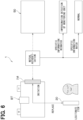
- the countermeasure regarding impersonation of the monitoring unit 20 will be described with reference to FIG. 6 .
- the impersonation of the monitoring unit 20 for example, as illustrated in FIG. 6 , a fraud in which monitoring data provided to a higher device is falsified by replacing the legitimate monitoring unit 20 with the imitation IM is conceivable.
- the battery-monitoring system 1 causes both the monitoring unit 20 and the battery ECU 50 to hold at least part of specific information including the unique ID, the manufacturing history of the battery BT, and the use history of the battery BT, causes the information authentication units 241 and 561 to perform mutual authentication of them, and determines whether there is no contradiction. For example, it is determined to be normal when the specific information match in both of the information authentication units 241 and 561, and it is determined to be impersonation of the monitoring unit 20 when the specific information mismatches in one of the information authentication units 241 and 561.
- the countermeasure regarding data counterfeit by signal interference will be described with reference to FIG. 7 .
- data counterfeit by signal interference a fraud in which a signal emitted from the legitimate monitoring unit 20 is interfered by the electromagnetic shield ES, and false monitoring data is provided from the imitation IM to the higher device is conceivable.
- the battery-monitoring system 1 provides monitoring data encrypted by the monitoring unit 20 to the higher device.
- the second information authentication unit 561 determines whether the monitoring data provided from the monitoring unit 20 is encrypted. The second information authentication unit 561 determines to be is normal when the monitoring data is encrypted, and determines to be data counterfeit when the monitoring data is not encrypted.
- a countermeasure regarding hijack of the higher device will be described with reference to FIG. 8 .
- the hijack of the higher device for example, as illustrated in FIG. 8 , a fraud in which the higher device is hijacked by hacking or the like and only data advantageous for the hijacker is requested from the monitoring unit 20 is conceivable.
- the monitoring unit 20 includes the diagnosis unit 243 that diagnoses appropriateness of a command signal transmitted from the higher device.
- This diagnosis unit 243 generates a learned model by learning the command signal from the higher device, and diagnoses appropriateness of the command signal by using the learned model.
- the diagnosis unit 243 determines to be normal when the command signal follows the past tendency, and diagnoses that the higher device is hijacked when the command signal does not follow the past tendency.
- the countermeasure regarding battery theft will be described with reference to FIG. 9 . If a replaceable battery is stolen, for example, as illustrated in FIG. 9 , there is a possibility that charging of the battery BT is performed by the charger CH installed in the charging stand CS or the like.
- the battery-monitoring system 1 causes both the monitoring unit 20 and the charger CH to hold the unique ID of the monitoring unit 20, causes the data authentication units 242 and AS to perform mutual authentication of them, and determines whether there is no contradiction.
- the monitoring unit 20 and the charger CH determine to be normal and permit charging.
- the monitoring unit 20 and the charger CH determine battery theft in a case where the unique IDs mismatch in one of the data authentication units 242 and AS. In this case, the charger CH prohibits charging of the battery BT.
- the monitoring unit 20, the battery ECU 50, and the like may prohibit discharging of the battery BT.
- the judgement of battery theft may be made by the user based on the position information of the battery BT, and charging or discharging may be prohibited by transferring that information to the monitoring unit 20, the battery ECU 50, or the charger CH.
- the countermeasure regarding battery theft described above can be performed not only between the monitoring unit 20 and the charger CH but also between the monitoring unit 20 and the battery ECU 50. That is, the battery-monitoring system 1 may be configured to cause both the monitoring unit 20 and the battery ECU 50 to hold the unique ID of the monitoring unit 20, cause the data authentication units 242 and 562 to perform mutual authentication of them, and determine whether there is no contradiction.
- the higher device is provided with monitoring data obtained by monitoring of the battery BT by the monitoring unit 20, and the higher device saves, by using a blockchain, at least part of specific information included in the monitoring data. According to this, the reliability of the battery-monitoring system 1 can be ensured.
- At least one of the monitoring unit 20 or the higher device is provided with a data protection unit configured to ensure reliability of the monitoring data. According to this, since the reliability of the monitoring data is secured by the data protection unit provided in at least one of the monitoring unit 20 or the higher device, the reliability of the data provided from the monitoring unit 20 to the higher device can be ensured.
- the higher device of the battery-monitoring system 1 prohibits charging of the battery BT in a case where an authentication result by the data authentication unit indicates a mismatch of the unique ID stored in each of the higher device and the monitoring unit 20.
- an authentication result by the data authentication unit indicates a mismatch of the unique ID stored in each of the higher device and the monitoring unit 20.
- the battery-monitoring system 1 can obtain the following effects.
- unauthorized access countermeasure it is conceivable to delete monitoring data stored in the storage unit 22 of the monitoring unit 20 when unauthorized access occurs, for example.
- the unauthorized access is access by a person who does not have a valid access authority. For example, in a case of unauthorized access by hijack or the like of the higher device, there is a possibility of performing leakage of monitoring data and the like of the monitoring unit 20 and unauthorized use and falsification of the monitoring data.
- the present embodiment proposes the battery-monitoring system 1 that can return to the flow of battery circulation even in the case of being subjected to unauthorized access while taking countermeasures against reading and falsification of monitoring data by unauthorized access.
- the first data protection unit 24 of the monitoring unit 20 is added with an access restriction unit 247 and an access cancellation unit 248.
- FIG. 10 for convenience, illustration of the first information authentication unit 241, the first data authentication unit 242, the diagnosis unit 243, the self-stopping unit 244, and the encrypted communication unit 245 of the first data protection unit 24 is omitted.
- the access restriction unit 247 restricts external access to the monitoring data stored in the storage unit 22 of the monitoring unit 20.
- the access restriction unit 247 restricts external access to the monitoring data when the unauthorized access is detected or predicted, for example.
- the access cancellation unit 248 cancels restriction of access to the monitoring data in a state where access to the monitoring data stored in the storage unit 22 is restricted by the access restriction unit 247. For example, when the cancellation key is notified from the higher device having a valid access authority, the access cancellation unit 248 cancels restriction of access to the monitoring data.
- the rest is the same as in the first embodiment.
- the battery-monitoring system 1 of the present embodiment can obtain, similarly to the first embodiment, effects achieved from a configuration common to or a configuration equivalent to that of the first embodiment.
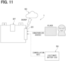
- the monitoring unit 20 executes the processing shown in FIG. 12 as a countermeasure against unauthorized access by hijack of the higher device as illustrated in FIG. 11 , for example.
- the processing shown in FIG. 12 is executed periodically or irregularly by the monitoring unit 20.
- step S100 the monitoring unit 20 determines whether unauthorized access to the monitoring data stored in the storage unit 22 is detected or predicted.
- the monitoring unit 20 detects unauthorized access based on a diagnosis result of a command signal by the diagnosis unit 243, for example.
- the monitoring unit 20 may judge the presence of unauthorized access not based on the diagnosis result of the diagnosis unit 243 but in a case where the authentication key at the time of accessing the monitoring unit 20 does not match or in a case where the password is continuously incorrect.
- the monitoring unit 20 predicts unauthorized access based on whether a similar action has been performed.
- the monitoring unit 20 judges that unauthorized access is predicted, for example, in a case where the order or the number of times of requesting various parameters representing the state of the battery BT is different from normal, in a case where the password is incorrect even once, or the like.
- the monitoring unit 20 waits until unauthorized access is detected or predicted, and when unauthorized access is detected or predicted, the process proceeds to step S110.
- the monitoring unit 20 stores, as backup data in an external storage device 60 such as a cloud server, the monitoring data stored in the storage unit 22.
- the backup data is desirably encrypted so as not to be discriminated from the outside.
- the external storage device 60 is provided outside the monitoring unit 20. Data communication between the external storage device 60 and the monitoring unit 20 is performed by wireless communication by OTA or the like or wired communication by a communication cable or the like.
- OTA is an abbreviation of over the air.
- step S120 the monitoring unit 20 deletes the monitoring data stored in the storage unit 22. This restricts access to the monitoring data stored in the storage unit 22.
- the processing in steps S110 and S120 described above are implemented by the access restriction unit 247.
- step S130 the monitoring unit 20 determines whether a cancellation key for releasing restriction on access is notified from a higher device having a valid access authority such as the legitimate battery ECU 50.
- step S140 the monitoring unit 20 acquires the backup data from the external storage device 60, and restores the monitoring data from the backup data to the storage unit 22. This cancels restriction of access to the monitoring data.
- the processing in step S140 described above is implemented by the access cancellation unit 248.
- the unauthorized access countermeasure of the first example described above it is possible to prevent reading and falsification of monitoring data by unauthorized access.
- the monitoring data is restored to the storage unit 22 from the backup data stored in the external storage device 60, it is possible to return to the flow of battery circulation even in a case of being subjected to unauthorized access.
- access to the monitoring data is restricted in the case where unauthorized access to the monitoring data is detected or predicted, but the present disclosure is not limited to this.
- the monitoring unit 20 may periodically restrict access to the monitoring data, or may restrict access to the monitoring data based on a command signal from the higher device. The same applies to the following examples.
- Backup of the monitoring data to the external storage device 60 is not limited to a case where unauthorized access to the monitoring data is detected or predicted, and may be regularly performed, for example. In a case where backup of the monitoring data to the external storage device 60 is regularly performed, when unauthorized access to the monitoring data is detected or predicted, the monitoring data may be deleted from the storage unit 22 without performing backup of the monitoring data.
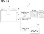
- the monitoring unit 20 executes the processing shown in FIG. 14 as a countermeasure against unauthorized access by hijack of the higher device as illustrated in FIG. 13 , for example.
- the processing shown in FIG. 14 is executed periodically or irregularly by the monitoring unit 20.
- step S200 the monitoring unit 20 determines whether unauthorized access to the monitoring data stored in the storage unit 22 is detected or predicted. Since this determination processing is similar to that of the first example, the description thereof will be omitted.
- the monitoring unit 20 prohibits information access to the storage unit 22 in step S210.
- the monitoring unit 20 prohibits information access to the storage unit 22 by, for example, interrupting communication between the outside and the storage unit 22 by stopping a function of the wireless communication device 25 or setting monitoring data unreadable. This restricts access to the monitoring data stored in the storage unit 22.
- the processing in step S210 described above is implemented by the access restriction unit 247.
- step S220 the monitoring unit 20 determines whether a cancellation key for releasing restriction on access is notified from a higher device having a valid access authority such as the legitimate battery ECU 50.
- step S230 processing of enabling information access to the storage unit 22 and permits information access to the storage unit 22. This cancels restriction of access to the monitoring data.
- the processing in step S230 described above is implemented by the access cancellation unit 248.
- the unauthorized access countermeasure of the second example described above it is possible to prevent reading and falsification of monitoring data by unauthorized access.
- the unauthorized access countermeasure of the present example has an advantage of being able to be implemented by simple processing of switching between prohibition and permission of information access to the storage unit 22.
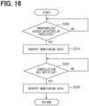
- the monitoring unit 20 executes the processing shown in FIG. 16 as a countermeasure against unauthorized access by hijack of the higher device as illustrated in FIG. 15 , for example.
- the processing shown in FIG. 16 is executed periodically or irregularly by the monitoring unit 20.
- step S300 the monitoring unit 20 determines whether unauthorized access to the monitoring data stored in the storage unit 22 is detected or predicted. Since this determination processing is similar to that of the first example, the description thereof will be omitted.
- the monitoring unit 20 When unauthorized access is detected or predicted, the monitoring unit 20 encrypts the monitoring data stored in the storage unit 22 in step S310.
- Examples of the encryption method include a public-key cryptography. This restricts access to the monitoring data stored in the storage unit 22.
- the processing in step S310 described above is implemented by the access restriction unit 247.
- step S320 the monitoring unit 20 determines whether a cancellation key for releasing restriction on access is notified from a higher device having a valid access authority such as the legitimate battery ECU 50.
- the monitoring unit 20 decrypts in step S330 the monitoring data to be encrypted. This cancels restriction of access to the monitoring data.
- the processing in step S330 described above is implemented by the access cancellation unit 248.
- the present example has an advantage of being able to implement a countermeasure against unauthorized access by simple processing of performing encryption and decryption of the monitoring data.
- the fourth example will be described with reference to FIGS. 17 and 18 .
- the monitoring unit 20 executes the processing shown in FIG. 18 as a countermeasure against unauthorized access by hijack of the higher device as illustrated in FIG. 17 , for example.
- the processing shown in FIG. 18 is executed periodically or irregularly by the monitoring unit 20.
- step S400 the monitoring unit 20 determines whether unauthorized access to the monitoring data stored in the storage unit 22 is detected or predicted. Since this determination processing is similar to that of the first example, the description thereof will be omitted.
- the monitoring unit 20 prohibits at least one of reading or rewriting of the monitoring data in step S410.
- the monitoring unit 20 prohibits at least one of reading or rewriting of the monitoring data by setting the access right of the folder storing the monitoring data to be unreadable or unrewritable. This restricts access to the monitoring data stored in the storage unit 22.
- the processing in step S410 described above is implemented by the access restriction unit 247.
- step S420 the monitoring unit 20 determines whether a cancellation key for releasing restriction on access is notified from a higher device having a valid access authority such as the legitimate battery ECU 50.
- the monitoring unit 20 When the cancellation key is notified from the higher device, the monitoring unit 20 permits reading and rewriting of the monitoring data in the storage unit 22 in step S430. This cancels restriction of access to the monitoring data.
- the processing in step S430 described above is implemented by the access cancellation unit 248.
- the present example has an advantage of being able to implement a countermeasure against unauthorized access by simple processing of performing setting change of the access right of the folder storing the monitoring data.
- the battery-monitoring system 1 is desirably configured to be able to cope with each of "impersonation of the monitoring unit 20", “data counterfeit by signal interference”, “hijack of a higher device”, “battery theft”, and “unauthorized access”, but the present disclosure is not limited to this.
- the battery-monitoring system 1 may be configured to be able to cope with a part of the fraud, or may be configured to be able to cope with another fraud other than the fraud described above.
- the higher device desirably saves, by using the blockchain, at least part of the specific information included in the monitoring data, but the present disclosure needs not be so.
- the sensor unit 21 of the monitoring unit 20 desirably includes the temperature sensor 211, the current sensor 212, the voltage sensor 213, the deterioration detection unit 214, and the SOH estimation unit 215, but the present disclosure is not limited to this.
- the sensor unit 21 of the monitoring unit 20 needs not be provided with, for example, the deterioration detection unit 214 and the SOH estimation unit 215.
- the first data protection unit 24 desirably includes the first information authentication unit 241, the first data authentication unit 242, the diagnosis unit 243, the self-stopping unit 244, the encrypted communication unit 245, the access restriction unit 247, and the access cancellation unit 248, but the present disclosure is not limited to this.
- the first data protection unit 24 needs not be provided with, for example, some of the first information authentication unit 241, the first data authentication unit 242, the diagnosis unit 243, the self-stopping unit 244, the encrypted communication unit 245, the access restriction unit 247, and the access cancellation unit 248.
- the second data protection unit 56 of the battery ECU 50 desirably includes the second information authentication unit 561, the second data authentication unit 562, the decryption processing unit 563, and the charging restriction unit 564, but the present disclosure is not limited to this.
- the second data authentication unit 562 needs not to be provided with, for example, some of the second information authentication unit 561, the second data authentication unit 562, the decryption processing unit 563, and the charging restriction unit 564.
- connection member WH includes the flexible printed circuit FPC, but the present disclosure is not limited to this, and the connection member WH needs not include the flexible printed circuit FPC.
- the battery ECU 50 and the charger CH are exemplified as the higher device of the monitoring unit 20, but the higher device may be configured by a device different from the battery ECU 50 and the charger CH.
- the battery-monitoring system 1 assumes the lithium ion battery as a monitoring target, but the present disclosure is not limited to this.
- the monitoring target of the battery-monitoring system 1 may be a battery other than the lithium ion battery.
- the battery-monitoring system 1 may have a configuration in which the monitoring unit 20 is connected to the higher device not wirelessly but by wire.
- the battery-monitoring system 1 is not limited to one that completely matches the one described above, and may be partially different from the one described above.
- the control unit and the method thereof of the present disclosure may be implemented by a dedicated computer provided by configuring a memory and a processor programmed to execute one or a plurality of functions embodied by a computer program.
- the control unit and the method thereof of the present disclosure may be implemented by a dedicated computer provided by configuring a processor by one or more dedicated hardware logic circuits.
- the control unit and the method thereof of the present disclosure may be implemented by one or more dedicated computers configured by a combination of a processor programmed to execute one or a plurality of functions and a memory and a processor configured by one or more hardware logic circuits.
- the computer program may be stored in a computer-readable non-transitory tangible recording medium as an instruction executed by the computer.
- a battery-monitoring system includes:
- each of the monitoring unit and the higher device includes an information authentication unit (241, 561) configured to perform mutual authentication on the specific information as the data protection unit.
- the monitoring unit includes, as the data protection unit, an encrypted communication unit (245) that encrypts and transmits, to the higher device, the monitoring data.
- the monitoring unit includes a diagnosis unit (243) that diagnoses appropriateness of a command signal transmitted from the higher device as the data protection unit.
- the diagnosis unit generates a learned model by learning the command signal from the higher device, and diagnoses the appropriateness of the command signal by using the learned model.
- the monitoring unit includes, as the data protection unit, a self-stopping unit (244) that stops its own function when the diagnosis unit diagnoses that the command signal is inappropriate.
- the monitoring unit includes, as the data protection unit, an access restriction unit (247) that restricts external access to the monitoring data stored in a storage unit (22) of the monitoring unit, and an access cancellation unit (248) that cancels restriction of the access when a preset cancellation key is notified from the higher device in a state where the access is restricted.
- a battery-monitoring system includes:
- a battery-monitoring system includes:
- the access restriction unit restricts external access to the monitoring data when the unauthorized access is detected or predicted.
Landscapes
- Engineering & Computer Science (AREA)
- General Physics & Mathematics (AREA)
- Physics & Mathematics (AREA)
- Computer Networks & Wireless Communication (AREA)
- Chemical & Material Sciences (AREA)
- Electrochemistry (AREA)
- General Chemical & Material Sciences (AREA)
- Chemical Kinetics & Catalysis (AREA)
- Manufacturing & Machinery (AREA)
- Power Engineering (AREA)
- Computer Security & Cryptography (AREA)
- Computer Hardware Design (AREA)
- Computing Systems (AREA)
- General Engineering & Computer Science (AREA)
- Signal Processing (AREA)
- Microelectronics & Electronic Packaging (AREA)
- Charge And Discharge Circuits For Batteries Or The Like (AREA)
- Secondary Cells (AREA)
Abstract
Description
- The present application is based on
Japanese Patent Application No. 2021-212555 filed on December 27, 2021 Japanese Patent Application No. 2022-198705 filed on December 13, 2022 - The present disclosure relates to a battery-monitoring system.
- In a battery-monitoring system, data obtained by a monitoring unit that is electrically connected to a battery and monitors the battery is transmitted to a higher device such as a battery control device or a battery charging device. There is a known technique in which raw data provided from a monitoring unit and processed data obtained by processing the raw data are encrypted by a higher device and managed by an autonomous distributed ledger (so-called blockchain) (see, for example, Patent Literature 1).
- Patent Literature 1:
European Patent Application Publication No. 3570058 - The technique disclosed in
Patent Literature 1 described above is very useful in enhancing the reliability of a higher device, but the reliability of the data itself provided from the monitoring unit is not secured at all, and the technique lacks reliability in this respect. - One object of the present disclosure is to provide a battery-monitoring system that can ensure reliability of data provided from a monitoring unit to a higher device. Another object of the present disclosure is to provide a battery-monitoring system that can return to a flow of battery circulation even in a case of being subjected to unauthorized access, or to provide a battery-monitoring system that can prevent theft of a battery.
- According to an aspect of the present disclosure,
a battery-monitoring system includes: - a monitoring unit that monitors a battery that is chargeable/dischargeable; and
- a higher device that is provided with monitoring data obtained by monitoring of the battery by the monitoring unit and saves, by using a blockchain, at least part of specific information included in the monitoring data, in which
- the higher device includes
- a block generation unit that generates a new block including a hash value based on at least part of the specific information and a last block linked at an end of the blockchain, and
- an external communication device configured to save, in a distributed manner in a plurality of external devices, the new block generated by the block generation unit, and
- at least one of the monitoring unit or the higher device is provided with a data protection unit configured to ensure reliability of the monitoring data.
- According to this, since the reliability of the monitoring data is secured by the data protection unit provided in the at least one of the monitoring unit or the higher device, the reliability of the data provided from the monitoring unit to the higher device can be ensured.
- According to another aspect of the present disclosure,
a battery-monitoring system includes: - a monitoring unit that monitors a battery that is chargeable/dischargeable; and
- a higher device that is provided with monitoring data obtained by monitoring of the battery by the monitoring unit, in which
- the monitoring unit is provided with a data protection unit configured to ensure reliability of the monitoring data, and
- the data protection unit includes an access restriction unit that restricts external access to the monitoring data stored in a storage unit of the monitoring unit, and an access cancellation unit that cancels restriction of the access when a preset cancellation key is notified from the higher device in a state where the access is restricted.
- Thus, when the access restriction unit is provided for the monitoring unit, reading and falsification of monitoring data by unauthorized access can be suppressed. In addition, since the access cancellation unit is provided for the monitoring unit, it is possible to return to the flow of battery circulation even in a case of being subjected to unauthorized access.
- Furthermore, according to another aspect of the present disclosure,
a battery-monitoring system includes: - a monitoring unit that monitors a battery that is chargeable/dischargeable; and
- a charger that controls charging of the battery, in which
- each of the monitoring unit and the charger stores a unique ID assigned to the monitoring unit,
- each of the monitoring unit and the charger includes a data authentication unit configured to perform mutual authentication of the unique ID, and
- the charger prohibits charging of the battery in a case where an authentication result by the data authentication unit indicates a mismatch of the unique ID stored in each of the charger and the monitoring unit.
- Thus, with a configuration that prohibits charging of the battery by the charger and loses the value of the battery in a case where unique IDs in the monitoring unit and the charger do not match, it is possible to demotivate a thief to steal the battery. This is very useful for preventing theft of the battery.
- A parenthesized reference sign attached to each constituent element or the like indicates an example of a correspondence relationship between the constituent element or the like and a specific constituent element or the like described in embodiments described later.
-
-
FIG. 1 is a schematic diagram of a battery-monitoring system according to a first embodiment. -
FIG. 2 is an explanatory diagram for explaining a lithium ion battery. -
FIG. 3 is a schematic configuration diagram of a monitoring unit and a battery ECU of the battery-monitoring system. -
FIG. 4 is an explanatory diagram for explaining a hash value of a new block. -
FIG. 5 is an explanatory diagram for explaining a blockchain. -
FIG. 6 is an explanatory diagram for explaining a countermeasure regarding impersonation by the monitoring unit. -
FIG. 7 is an explanatory diagram for explaining a countermeasure regarding data counterfeit by signal interference. -
FIG. 8 is an explanatory diagram for explaining a countermeasure regarding hijack of a higher device. -
FIG. 9 is an explanatory diagram for explaining a countermeasure regarding battery theft. -
FIG. 10 is a schematic diagram of a battery-monitoring system according to a second embodiment. -
FIG. 11 is an explanatory diagram for explaining a first example of a countermeasure regarding unauthorized access. -
FIG. 12 is a flowchart showing a flow of countermeasure processing of unauthorized access by the monitoring unit. -
FIG. 13 is an explanatory diagram for explaining a second example of the countermeasure regarding unauthorized access. -
FIG. 14 is a flowchart showing a flow of countermeasure processing of unauthorized access by the monitoring unit. -
FIG. 15 is an explanatory diagram for explaining a third example of the countermeasure regarding unauthorized access. -
FIG. 16 is a flowchart showing a flow of countermeasure processing of unauthorized access by the monitoring unit. -
FIG. 17 is an explanatory diagram for explaining a fourth example of the countermeasure regarding unauthorized access. -
FIG. 18 is a flowchart showing a flow of countermeasure processing of unauthorized access by the monitoring unit. - Hereinafter, embodiments of the present disclosure will be described with reference to the drawings. In the following embodiments, identical or equivalent parts to those described in preceding embodiments are denoted by identical reference signs, and the description thereof may be omitted. When only some of the constituent elements are described in the embodiments, the other of the constituent elements can be applied with constituent elements described in preceding embodiments. In the following embodiments, the embodiments can be partially combined with one another even if not particularly specified as long as the combination is not particularly hindered.
- The first embodiment of the present disclosure will be described with reference to
FIGS. 1 to 9 . A battery-monitoringsystem 1 is a system that monitors a battery BT that is chargeable/dischargeable such as a high-voltage battery, a stationary battery, or a portable battery to be mounted on an automobile. - As illustrated in
FIG. 1 , the battery-monitoringsystem 1 includes amonitoring unit 20 that monitors the battery BT, and abattery ECU 50 provided with monitoring data obtained by monitoring of the battery BT by themonitoring unit 20. Thebattery ECU 50 is a higher device present above themonitoring unit 20. The battery-monitoringsystem 1 may include a charger CH that can control charging of the battery BT in place of thebattery ECU 50. In this case, the charger CH corresponds to the higher device. Hereinafter, thebattery ECU 50 and the charger CH may be called a higher device. - The battery BT that is a monitoring target is a secondary battery that is chargeable/dischargeable. The battery BT may be constituted by one battery cell, or may be constituted by an assembled battery in which a plurality of battery cells are connected in series. In the assembled battery, some battery cells may be connected in parallel.
- Specifically, the battery BT includes a lithium ion battery. For example, as illustrated in
FIG. 2 , the lithium ion battery is configured by employing lithium ferro-phosphate LFP or nickel-manganese-cobalt NMC as a positive electrode agent, and employing graphite as a negative electrode agent. In the lithium ion battery, for example, a positive electrode side current collector includes aluminum, and a negative electrode side current collector includes copper. The lithium ion battery thus configured has excellent cycle characteristics of charge and discharge, but has a characteristic that the electrode potential is very close to the deposition potential of lithium, and lithium is likely to be deposited in a charged state. - As illustrated in
FIG. 3 , themonitoring unit 20 is electrically connected to the battery BT via a connection member WH. Themonitoring unit 20 may be integrally attached to the battery BT or may be detachably attached to the battery BT. The connection member WH includes a flexible printed circuit FPC on which a wiring pattern is printed. - The
monitoring unit 20 includes asensor unit 21, astorage unit 22, a firstdata protection unit 24, and awireless communication device 25. InFIG. 3 , each constituent element of themonitoring unit 20 is surrounded by a quadrilateral frame, but this is for collectively indicating each constituent element, and does not indicate that each constituent element is mounted on a single board. - The
sensor unit 21 detects a state of the battery BT. Thesensor unit 21 includes atemperature sensor 211, acurrent sensor 212, avoltage sensor 213, adeterioration detection unit 214, and anSOH estimation unit 215. - The
temperature sensor 211 is a sensor that detects the battery temperature of the lithium ion battery. Thetemperature sensor 211 is mounted on the flexible printed circuit FPC, for example. The battery temperature may be estimated from a measurement result of internal impedance of the battery BT. In this case, the means for estimating the battery temperature functions as thetemperature sensor 211. - The
current sensor 212 is a sensor that detects an output current of the battery BT. Thecurrent sensor 212 may be mounted on the flexible printed circuit FPC, for example, or may be mounted on a board other than the flexible printed circuit FPC. - The
voltage sensor 213 is a sensor that detects an output voltage of the battery BT. Thevoltage sensor 213 may be mounted on the flexible printed circuit FPC, for example, or may be mounted on a board other than the flexible printed circuit FPC. - The
deterioration detection unit 214 detects a deterioration degree of the battery BT, which serves as an important index in setting a residual value of the battery BT. Thedeterioration detection unit 214 includes a depositionamount detection unit 214a and acoating detection unit 214b. - The deposition
amount detection unit 214a is a device that detects lithium deposition in the lithium ion battery. Using a correlation between the lithium deposition amount in the lithium ion battery and behavior of the current and the voltage when both ends of the lithium ion battery are short-circuited, the depositionamount detection unit 214a estimates a lithium deposition amount from the behavior. Although not illustrated, the depositionamount detection unit 214a includes a short circuit that temporarily short-circuits both ends of the lithium ion battery to discharge, and a calculator that estimates the lithium deposition amount based on the behavior of the current and the voltage when the lithium ion battery is short-circuited by the short circuit. The short circuit includes a short circuit switch, a coil, and a capacitor for short-circuiting both ends of the lithium ion battery. The internal resistance of the lithium ion battery and the coil and the capacitor of the short circuit constitute a self-resonant circuit. When both ends of the lithium ion battery are short-circuited, the calculator extracts a resistance change component having a correlation with the lithium deposition amount included in a signal waveform of at least one of the current or the voltage flowing through the short circuit, and calculates an estimation value of the lithium deposition amount from the extracted component. - Such an estimation method for the lithium deposition amount has a very simple configuration, and is a very useful method in that a specific battery deterioration mode can be detected by adjusting the discharge frequency from the lithium ion battery. The deposition
amount detection unit 214a calculates, as the lithium deposition amount, a correction value in which the estimation value of the lithium deposition amount is corrected with at least one of the battery temperature detected by thetemperature sensor 211 or a parasitic resistance value stored in advance in thestorage unit 22 described later. The depositionamount detection unit 214a may estimate the lithium deposition amount by a method other than the above. - The
coating detection unit 214b detects the thickness of a coating formed at an interface between a negative electrode and an electrolytic solution at the time of charging of the lithium ion battery. This coating is also called an SEI layer. SEI is an abbreviation for solid electrolyte interphase. The thickness of the SEI layer has a correlation with the behavior of the current and the voltage when both ends of the lithium ion battery are short-circuited by the above-described short circuit. Thecoating detection unit 214b estimates the thickness of the SEI layer from the behavior of the current and the voltage when both ends of the lithium ion battery are short-circuited by the short circuit. Specifically, when both ends of the battery BT are short-circuited by the short circuit, thecoating detection unit 214b extracts a component having a correlation with the thickness of the SEI layer included in the signal waveform of at least one of the current or the voltage flowing through the short circuit, and estimates the thickness of the SEI layer from the extracted component. When the thickness of the SEI layer is detected, it is desirable to correct the thickness by the battery temperature or the like similarly to the detection of the lithium deposition amount. Thecoating detection unit 214b may estimate the thickness of the SEI layer by a method other than the above. - Here, the internal resistance of the battery BT and the cracking degree of a positive electrode active substance agent inside the battery BT are physical quantities that directly affect the deterioration of the battery BT. Therefore, the
deterioration detection unit 214 may include a detection unit of the internal resistance of the battery BT and a detection unit of the cracking degree of the positive electrode active substance agent inside the battery BT. - The
SOH estimation unit 215 estimates a volume ratio SOH of the battery BT based on a physical quantity having a high correlation with capacity deterioration of the battery BT. One factor of deterioration of the battery BT is an increase in the internal resistance of the battery BT. The internal resistance of the battery BT has a strong correlation with physical quantities such as the lithium deposition amount and the internal resistance of the battery BT. The internal resistance of the battery BT has temperature dependency, and affects the current and voltage of the battery BT. SOH is an abbreviation for state of health. - In consideration of these, the
SOH estimation unit 215 of the present embodiment estimates the volume ratio SOH using an estimation model of the lithium deposition amount, the thickness of the SEI layer, the temperature, the current, and the voltage of the battery BT, and the volume ratio SOH. The estimation model of the volume ratio SOH is a control map or a function that defines, for example, the relationship among the volume ratio SOH, the lithium deposition amount, the thickness of the SEI layer, and the temperature, the current, and the voltage of the battery BT. TheSOH estimation unit 215 may estimate the volume ratio SOH of the battery BT by a method other than the above. Although not illustrated, themonitoring unit 20 also includes an estimation unit that estimates a residual capacity SOC of the battery BT. - The
storage unit 22 includes a readable and writable storage medium. Thestorage unit 22 stores a detection result of the state of the battery BT by thesensor unit 21, and the like. Specifically, thestorage unit 22 stores a unique ID set for eachmonitoring unit 20 and a manufacturing history of the battery BT including an initial capacity of the battery BT and a repair history of the battery BT. Thestorage unit 22 stores, for example, the lithium deposition amount, the thickness of the SEI layer, the internal resistance of the battery BT, the volume ratio SOH, and the like as a use history of the battery BT. Hereinafter, the unique ID, the manufacturing history of the battery BT, and the use history of the battery BT are also collectively called "specific information". Thestorage unit 22 includes a non-transitory tangible storage medium. - A
monitoring control unit 23 monitors the detection result of the state of the battery BT by thesensor unit 21, and determines the appropriateness of the state of the battery BT based on this monitoring result. When an abnormality of the battery BT is detected, themonitoring control unit 23 notifies the higher device such as thebattery ECU 50 of the abnormality of the battery BT via thewireless communication device 25. - The first
data protection unit 24 is for ensuring reliability of monitoring data provided from themonitoring unit 20 to the higher device such as thebattery ECU 50 via thewireless communication device 25. The firstdata protection unit 24 will be described later. - The
wireless communication device 25 is a device for enabling bidirectional communication with the higher device such as thebattery ECU 50. Themonitoring unit 20 receives various signals from the higher device such as thebattery ECU 50 and transmits, to the higher device such as thebattery ECU 50, monitoring data and the like obtained by monitoring of the battery BT by themonitoring unit 20. The monitoring data includes specific information such as the unique ID, the manufacturing history of the battery BT, the use history of the battery BT, and position information of the battery BT. - Next, the
battery ECU 50 will be described. Thebattery ECU 50 is a higher device in the battery-monitoringsystem 1. Thebattery ECU 50 performs charging/discharging control of the battery BT and temperature adjustment control of the battery BT by a temperature control device based on monitoring data or the like provided from themonitoring unit 20. Thebattery ECU 50 includes a charging control function for controlling charging of the battery BT. - Specifically, the
battery ECU 50 is configured to include a microcomputer including a processor, amemory 51, and an I/O and aninternal communication device 52 configured to bidirectionally communicating with themonitoring unit 20. Thememory 51 includes a non-transitory tangible storage medium. - It is expected that a large amount of used batteries BT will be generated in the near future due to rapid electrification of automobiles. Manufacturing the battery BT involves a large amount of CO2 emissions and use of rare metals. For this reason, through selection of reuse, rebuild, and recycle in accordance with the residual capacity SOC and the volume ratio SOH of the battery BT, construction of a battery ecosystem adapted to a circular society is expected for the used battery BT. In order to construct such a battery ecosystem, a traceability system that associates and manages values of the battery BT such as the residual capacity SOC and the volume ratio SOH and information such as the manufacturing history and the use history of the battery BT with the battery BT itself is important. It is assumed that a user who wants to use the battery BT accesses the traceability system, grasps necessary battery information, and uses the battery BT at an amount of money commensurate with the values of the battery BT. In such a traceability system, reliability of saved battery information is very important.
- Under such a background, the battery-monitoring
system 1 of the present disclosure improves the reliability of the traceability system by utilizing the blockchain technology in the traceability system. The blockchain technology is a type of database in which terminals on an information communication network are directly connected to one another, and a use history and the like of the battery 10 are processed and recorded in a distributed manner using an encryption technology. - The battery-monitoring
system 1 of the present disclosure is configured to be able to provide, as reliable and updated data, a parameter representing a state of the battery BT used for a long period of time. That is, the battery-monitoringsystem 1 encrypts (i.e., hashes) monitoring data provided from themonitoring unit 20 and the parameter obtained by calculating the monitoring data using the higher device such as thebattery ECU 50 and the charger CH. Then, the higher device manages the data in an autonomous distributed ledger (i.e., the blockchain), thereby improving the reliability of the battery-monitoringsystem 1. - Specifically, in the battery-monitoring
system 1, thebattery ECU 50 saves, using the blockchain, at least part of the specific information included in the monitoring data provided from themonitoring unit 20. Thebattery ECU 50 is configured to include ablock generation unit 53, astorage 54, anexternal communication device 55, and a seconddata protection unit 56. - For example, as illustrated in
FIG. 4 , theblock generation unit 53 generates a new block Bn including a hash value based on a last block Be linked at the end of the blockchain in addition to specific information including the unique ID, the manufacturing history of the battery BT, and the use history of the battery BT. - The
battery ECU 50 saves the new block Bn generated by theblock generation unit 53 into thestorage 54 of its own, and, using theexternal communication device 55, saves, in a distributed manner, the new block Bn into a plurality of external devices connected via an Internet INT. For example, a battery-monitoring system 1A illustrated inFIG. 5 saves, in a distributed manner, the new block Bn into thestorage 54 of each of battery-monitoringsystems systems - In such a traceability system, the data saved in the
storage 54 is protected from falsification by the blockchain technology, and therefore the reliability of the battery-monitoringsystem 1 is greatly improved. - However, the blockchain technology is a technology for protecting, from falsification, data saved in the
storage 54, and the reliability of data itself provided from themonitoring unit 20 to the higher device is not secured at all. For this reason, there is a possibility that monitoring data different from actual one is accumulated in thestorage 54 due to impersonation of themonitoring unit 20 by an imitation IM or data counterfeit by interference of a transmission signal of themonitoring unit 20 by an electromagnetic shield ES. This becomes a factor that damages the reliability of the traceability system. - When a higher device such as the
battery ECU 50 is hijacked by hacking or the like, there is a possibility that various types of information are intentionally manipulated. Specifically, a case of interrupting communication from themonitoring unit 20, performing control so that the volume ratio SOH or the like of the battery BT is not updated, and determining that the battery BT is not deteriorated is assumed. Thus, even in a case where the higher device is hijacked, there is a problem that the reliability of data is impaired. - Furthermore, in the battery BT that is portable such as a replaceable battery, even if data is managed by the blockchain technology, if the data is stolen by a thief, the user loses the value of the battery BT, and a third party enjoys the value. Therefore, a countermeasure against theft becomes a problem.
- In consideration of these, the battery-monitoring
system 1 is provided with the data protection unit for ensuring the reliability of monitoring data. Specifically, in the battery-monitoringsystem 1, themonitoring unit 20 is provided with the firstdata protection unit 24, and thebattery ECU 50 is provided with the seconddata protection unit 56. - More specifically, the
monitoring unit 20 includes, as the firstdata protection unit 24, a firstinformation authentication unit 241, a firstdata authentication unit 242, adiagnosis unit 243, a self-stoppingunit 244, and anencrypted communication unit 245. - The first
information authentication unit 241 is an authentication unit that performs mutual authentication on specific information provided from themonitoring unit 20 to thebattery ECU 50 between the firstinformation authentication unit 241 and thebattery ECU 50. The firstinformation authentication unit 241 determines whether the specific information included in themonitoring unit 20 matches the specific information included in thebattery ECU 50. - The first
data authentication unit 242 is an authentication unit that performs mutual authentication on a unique ID assigned to themonitoring unit 20 between the firstdata authentication unit 242 and thebattery ECU 50. The firstdata authentication unit 242 determines whether the unique ID included in themonitoring unit 20 matches the unique ID included in thebattery ECU 50. - The
diagnosis unit 243 diagnoses appropriateness of a command signal transmitted from a higher device. Thediagnosis unit 243 generates a learned model by learning the command signal from the higher device, and diagnoses appropriateness of the command signal by using the learned model. Thediagnosis unit 243 generates the learned model by learning the tendency of the command signal from the higher device, for example. - The self-stopping
unit 244 stops the function of themonitoring unit 20. The self-stoppingunit 244 stops its own function, for example, when thediagnosis unit 243 diagnoses that the command signal from the higher device is inappropriate. The self-stoppingunit 244 stops the function of themonitoring unit 20 by cutting off power supply to an IC constituting themonitoring unit 20, for example. - The
encrypted communication unit 245 encrypts and transmits, to the higher device, the monitoring data. Theencrypted communication unit 245 is configured to include anencryption processing unit 246 that encrypts the monitoring data and thewireless communication device 25. - On the other hand, the
battery ECU 50 includes, as the seconddata protection unit 56, a secondinformation authentication unit 561, a seconddata authentication unit 562, adecryption processing unit 563, and acharging restriction unit 564. - The second
information authentication unit 561 is an authentication unit that performs mutual authentication on specific information provided from themonitoring unit 20 to thebattery ECU 50 between the secondinformation authentication unit 561 and themonitoring unit 20. The secondinformation authentication unit 561 determines whether the information included in themonitoring unit 20 matches the information included in thebattery ECU 50. - The second
data authentication unit 562 is an authentication unit that performs mutual authentication on a unique ID assigned to themonitoring unit 20 between the seconddata authentication unit 562 and themonitoring unit 20. The seconddata authentication unit 562 determines whether the unique ID included in themonitoring unit 20 matches the unique ID included in thebattery ECU 50. - The
decryption processing unit 563 is provided corresponding to theencrypted communication unit 245 of themonitoring unit 20. Thedecryption processing unit 563 decrypts, by predetermined decryption processing, the monitoring data encrypted by theencryption processing unit 246. - The charging
restriction unit 564 restricts charging of the battery BT. For example, in a case where authentication results of the firstdata authentication unit 242 and the seconddata authentication unit 562 indicate a mismatch of the unique ID stored in each of the higher device and themonitoring unit 20, the chargingrestriction unit 564 prohibits charging of the battery BT. - Here, the charger CH installed in a charging stand CS or the like is a higher device of the
monitoring unit 20 of the battery BT together with thebattery ECU 50. The charger CH controls charging of the battery BT. The charger CH is provided with a data authentication unit AS corresponding to the seconddata authentication unit 562 and a controller CR corresponding to the chargingrestriction unit 564. - In the battery-monitoring
system 1 thus configured, since the data protection unit is provided in themonitoring unit 20 and the higher device, it is possible to take effective countermeasures against impersonation of themonitoring unit 20, data counterfeit by signal interference, hijack of the higher device, and battery theft. Hereinafter, countermeasures regarding impersonation of themonitoring unit 20, data counterfeit by signal interference, hijack of the higher device, and battery theft will be described. - The countermeasure regarding impersonation of the
monitoring unit 20 will be described with reference toFIG. 6 . As the impersonation of themonitoring unit 20, for example, as illustrated inFIG. 6 , a fraud in which monitoring data provided to a higher device is falsified by replacing thelegitimate monitoring unit 20 with the imitation IM is conceivable. - On the other hand, the battery-monitoring
system 1 causes both themonitoring unit 20 and thebattery ECU 50 to hold at least part of specific information including the unique ID, the manufacturing history of the battery BT, and the use history of the battery BT, causes theinformation authentication units information authentication units monitoring unit 20 when the specific information mismatches in one of theinformation authentication units - The countermeasure regarding data counterfeit by signal interference will be described with reference to
FIG. 7 . For example, as illustrated inFIG. 7 , as data counterfeit by signal interference, a fraud in which a signal emitted from thelegitimate monitoring unit 20 is interfered by the electromagnetic shield ES, and false monitoring data is provided from the imitation IM to the higher device is conceivable. - On the other hand, the battery-monitoring
system 1 provides monitoring data encrypted by themonitoring unit 20 to the higher device. In the higher device, the secondinformation authentication unit 561 determines whether the monitoring data provided from themonitoring unit 20 is encrypted. The secondinformation authentication unit 561 determines to be is normal when the monitoring data is encrypted, and determines to be data counterfeit when the monitoring data is not encrypted. - A countermeasure regarding hijack of the higher device will be described with reference to
FIG. 8 . As the hijack of the higher device, for example, as illustrated inFIG. 8 , a fraud in which the higher device is hijacked by hacking or the like and only data advantageous for the hijacker is requested from themonitoring unit 20 is conceivable. - On the other hand, in the battery-monitoring
system 1, themonitoring unit 20 includes thediagnosis unit 243 that diagnoses appropriateness of a command signal transmitted from the higher device. Thisdiagnosis unit 243 generates a learned model by learning the command signal from the higher device, and diagnoses appropriateness of the command signal by using the learned model. Thediagnosis unit 243 determines to be normal when the command signal follows the past tendency, and diagnoses that the higher device is hijacked when the command signal does not follow the past tendency. - The countermeasure regarding battery theft will be described with reference to
FIG. 9 . If a replaceable battery is stolen, for example, as illustrated inFIG. 9 , there is a possibility that charging of the battery BT is performed by the charger CH installed in the charging stand CS or the like. - On the other hand, the battery-monitoring
system 1 causes both themonitoring unit 20 and the charger CH to hold the unique ID of themonitoring unit 20, causes thedata authentication units 242 and AS to perform mutual authentication of them, and determines whether there is no contradiction. For example, when the unique IDs match in both thedata authentication units 242 and AS, themonitoring unit 20 and the charger CH determine to be normal and permit charging. On the other hand, themonitoring unit 20 and the charger CH determine battery theft in a case where the unique IDs mismatch in one of thedata authentication units 242 and AS. In this case, the charger CH prohibits charging of the battery BT. Alternatively, in a case where battery theft is judged, themonitoring unit 20, thebattery ECU 50, and the like may prohibit discharging of the battery BT. The judgement of battery theft may be made by the user based on the position information of the battery BT, and charging or discharging may be prohibited by transferring that information to themonitoring unit 20, thebattery ECU 50, or the charger CH. - The countermeasure regarding battery theft described above can be performed not only between the monitoring
unit 20 and the charger CH but also between the monitoringunit 20 and thebattery ECU 50. That is, the battery-monitoringsystem 1 may be configured to cause both themonitoring unit 20 and thebattery ECU 50 to hold the unique ID of themonitoring unit 20, cause thedata authentication units - In the battery-monitoring
system 1 described above, the higher device is provided with monitoring data obtained by monitoring of the battery BT by themonitoring unit 20, and the higher device saves, by using a blockchain, at least part of specific information included in the monitoring data. According to this, the reliability of the battery-monitoringsystem 1 can be ensured. - Furthermore, at least one of the
monitoring unit 20 or the higher device is provided with a data protection unit configured to ensure reliability of the monitoring data. According to this, since the reliability of the monitoring data is secured by the data protection unit provided in at least one of themonitoring unit 20 or the higher device, the reliability of the data provided from themonitoring unit 20 to the higher device can be ensured. - In addition, the higher device of the battery-monitoring
system 1 prohibits charging of the battery BT in a case where an authentication result by the data authentication unit indicates a mismatch of the unique ID stored in each of the higher device and themonitoring unit 20. Thus, with a configuration that prohibits charging of the battery BT and loses the value of the battery BT in a case where the unique IDs in themonitoring unit 20 and the higher device do not match, it is possible to demotivate a thief to steal the battery BT. This is very useful for preventing theft of the battery BT. - The battery-monitoring
system 1 can obtain the following effects. - (1) Each of the
monitoring unit 20 and the higher device includes an information authentication unit configured to perform mutual authentication on the specific information as the data protection unit. According to this, it is possible to detect a fraud in which monitoring data provided to a higher device is falsified by replacing thelegitimate monitoring unit 20 with the imitation IM, for example. As a result, it is possible to prevent falsification of monitoring data by impersonation of themonitoring unit 20. - (2) The
monitoring unit 20 includes, as the data protection unit, theencrypted communication unit 245 that encrypts and transmits, to the higher device, the monitoring data. Thus, if the monitoring data provided from themonitoring unit 20 to the higher device is encrypted, it is possible for the higher device to detect a fraud in which a signal from thelegitimate monitoring unit 20 is interfered and false monitoring data is provided to the higher device. As a result, it is possible to prevent counterfeit of monitoring data. - (3) The
monitoring unit 20 includes thediagnosis unit 243 that diagnoses appropriateness of a command signal transmitted from the higher device as the data protection unit. According to this, for example, a fraud in which only data advantageous for the impersonator is requested from themonitoring unit 20 through impersonation of the higher device can be detected on themonitoring unit 20 side. As a result, it is possible to prevent falsification of monitoring data by impersonation of the higher device. - (4) The
diagnosis unit 243 generates a learned model by learning the command signal from the higher device, and diagnoses appropriateness of the command signal by using the learned model. According to this, it is possible to reflect, in the learned model, the tendency of the command signal that requests only data advantageous for the hijacker is requested from the higher device, and improve accuracy of detecting hijack of the higher device. - (5) The
monitoring unit 20 includes, as the data protection unit, the self-stoppingunit 244 that stops its own function when thediagnosis unit 243 diagnoses that the command signal is inappropriate. According to this, it is possible to suppress spread of damage by a fraud in which only data advantageous for the impersonator is requested from themonitoring unit 20 through impersonation of the higher device. - Next, the second embodiment will be described with reference to
FIGS. 10 to 18 . In the present embodiment, differences from the first embodiment will be mainly described. - In recent years, in order to realize circular economy, a trend of securely using up battery resources has been intensified, and it is predicted that a society that can appropriately control the cycle of "manufacturing of the battery BT" → "temporary use" → "secondary use" → "recycle" will come in the near future. The future battery circulation society is considered to require a system in which data of the number of held batteries and the health state in each process of battery use is grasped on a cloud, when and what kind of the battery BT to be supplied are predicted for each process, and a production plan can be optimized.
- In order to realize such a circulation society, reliability of monitoring data including sensing information such as a health state of the battery BT is important, and a countermeasure against unauthorized access to a system including the battery BT is required. As an unauthorized access countermeasure, it is conceivable to delete monitoring data stored in the
storage unit 22 of themonitoring unit 20 when unauthorized access occurs, for example. The unauthorized access is access by a person who does not have a valid access authority. For example, in a case of unauthorized access by hijack or the like of the higher device, there is a possibility of performing leakage of monitoring data and the like of themonitoring unit 20 and unauthorized use and falsification of the monitoring data. - However, in a case of deleting monitoring data stored in the
storage unit 22 of themonitoring unit 20 as an unauthorized access countermeasure, the health state or the like of the battery BT becomes unknown. In this case, there is a problem of not being able to judge whether to be usable in "secondary use", and not being able to effectively use the battery BT in circulation of "temporary use" → "recycle". - In consideration of these, the present embodiment proposes the battery-monitoring
system 1 that can return to the flow of battery circulation even in the case of being subjected to unauthorized access while taking countermeasures against reading and falsification of monitoring data by unauthorized access. - As illustrated in
FIG. 10 , in the battery-monitoringsystem 1 of the present embodiment, the firstdata protection unit 24 of themonitoring unit 20 is added with anaccess restriction unit 247 and anaccess cancellation unit 248. InFIG. 10 , for convenience, illustration of the firstinformation authentication unit 241, the firstdata authentication unit 242, thediagnosis unit 243, the self-stoppingunit 244, and theencrypted communication unit 245 of the firstdata protection unit 24 is omitted. - The
access restriction unit 247 restricts external access to the monitoring data stored in thestorage unit 22 of themonitoring unit 20. Theaccess restriction unit 247 restricts external access to the monitoring data when the unauthorized access is detected or predicted, for example. - The
access cancellation unit 248 cancels restriction of access to the monitoring data in a state where access to the monitoring data stored in thestorage unit 22 is restricted by theaccess restriction unit 247. For example, when the cancellation key is notified from the higher device having a valid access authority, theaccess cancellation unit 248 cancels restriction of access to the monitoring data. - The rest is the same as in the first embodiment. The battery-monitoring
system 1 of the present embodiment can obtain, similarly to the first embodiment, effects achieved from a configuration common to or a configuration equivalent to that of the first embodiment. - Specific examples regarding unauthorized access countermeasures in the
monitoring unit 20 will be described below. in the following first to fourth examples, the examples can be partially combined with one another even if not particularly specified as long as the combination is not particularly hindered. - First, the first example will be described with reference to
FIGS. 11 and12 . Themonitoring unit 20 executes the processing shown inFIG. 12 as a countermeasure against unauthorized access by hijack of the higher device as illustrated inFIG. 11 , for example. The processing shown inFIG. 12 is executed periodically or irregularly by themonitoring unit 20. - As shown in
FIG. 12 , in step S100, themonitoring unit 20 determines whether unauthorized access to the monitoring data stored in thestorage unit 22 is detected or predicted. - The
monitoring unit 20 detects unauthorized access based on a diagnosis result of a command signal by thediagnosis unit 243, for example. Themonitoring unit 20 may judge the presence of unauthorized access not based on the diagnosis result of thediagnosis unit 243 but in a case where the authentication key at the time of accessing themonitoring unit 20 does not match or in a case where the password is continuously incorrect. - For example, even in a case of not being able to determine unauthorized access, the
monitoring unit 20 predicts unauthorized access based on whether a similar action has been performed. Themonitoring unit 20 judges that unauthorized access is predicted, for example, in a case where the order or the number of times of requesting various parameters representing the state of the battery BT is different from normal, in a case where the password is incorrect even once, or the like. - The
monitoring unit 20 waits until unauthorized access is detected or predicted, and when unauthorized access is detected or predicted, the process proceeds to step S110. In step S110, themonitoring unit 20 stores, as backup data in anexternal storage device 60 such as a cloud server, the monitoring data stored in thestorage unit 22. The backup data is desirably encrypted so as not to be discriminated from the outside. - The
external storage device 60 is provided outside themonitoring unit 20. Data communication between theexternal storage device 60 and themonitoring unit 20 is performed by wireless communication by OTA or the like or wired communication by a communication cable or the like. OTA is an abbreviation of over the air. - Subsequently, in step S120, the
monitoring unit 20 deletes the monitoring data stored in thestorage unit 22. This restricts access to the monitoring data stored in thestorage unit 22. The processing in steps S110 and S120 described above are implemented by theaccess restriction unit 247. - Subsequently, in step S130, the
monitoring unit 20 determines whether a cancellation key for releasing restriction on access is notified from a higher device having a valid access authority such as thelegitimate battery ECU 50. - The
monitoring unit 20 waits until the cancellation key is notified, and when the cancellation key is notified from the higher device, the process proceeds to step S140. In step S140, themonitoring unit 20 acquires the backup data from theexternal storage device 60, and restores the monitoring data from the backup data to thestorage unit 22. This cancels restriction of access to the monitoring data. The processing in step S140 described above is implemented by theaccess cancellation unit 248. - According to the unauthorized access countermeasure of the first example described above, it is possible to prevent reading and falsification of monitoring data by unauthorized access. In particular, in the present example, since the monitoring data is restored to the
storage unit 22 from the backup data stored in theexternal storage device 60, it is possible to return to the flow of battery circulation even in a case of being subjected to unauthorized access. - In the first example, access to the monitoring data is restricted in the case where unauthorized access to the monitoring data is detected or predicted, but the present disclosure is not limited to this. For example, the
monitoring unit 20 may periodically restrict access to the monitoring data, or may restrict access to the monitoring data based on a command signal from the higher device. The same applies to the following examples. - Backup of the monitoring data to the
external storage device 60 is not limited to a case where unauthorized access to the monitoring data is detected or predicted, and may be regularly performed, for example. In a case where backup of the monitoring data to theexternal storage device 60 is regularly performed, when unauthorized access to the monitoring data is detected or predicted, the monitoring data may be deleted from thestorage unit 22 without performing backup of the monitoring data. - Next, the second example will be described with reference to
FIGS. 13 and14 . Themonitoring unit 20 executes the processing shown inFIG. 14 as a countermeasure against unauthorized access by hijack of the higher device as illustrated inFIG. 13 , for example. The processing shown inFIG. 14 is executed periodically or irregularly by themonitoring unit 20. - As shown in
FIG. 14 , in step S200, themonitoring unit 20 determines whether unauthorized access to the monitoring data stored in thestorage unit 22 is detected or predicted. Since this determination processing is similar to that of the first example, the description thereof will be omitted. - When unauthorized access is detected or predicted, the
monitoring unit 20 prohibits information access to thestorage unit 22 in step S210. Themonitoring unit 20 prohibits information access to thestorage unit 22 by, for example, interrupting communication between the outside and thestorage unit 22 by stopping a function of thewireless communication device 25 or setting monitoring data unreadable. This restricts access to the monitoring data stored in thestorage unit 22. The processing in step S210 described above is implemented by theaccess restriction unit 247. - Subsequently, in step S220, the
monitoring unit 20 determines whether a cancellation key for releasing restriction on access is notified from a higher device having a valid access authority such as thelegitimate battery ECU 50. - When the cancellation key is notified from the higher device, the
monitoring unit 20 performs in step S230 processing of enabling information access to thestorage unit 22 and permits information access to thestorage unit 22. This cancels restriction of access to the monitoring data. The processing in step S230 described above is implemented by theaccess cancellation unit 248. - According to the unauthorized access countermeasure of the second example described above, it is possible to prevent reading and falsification of monitoring data by unauthorized access. In particular, the unauthorized access countermeasure of the present example has an advantage of being able to be implemented by simple processing of switching between prohibition and permission of information access to the
storage unit 22. - Next, the third example will be described with reference to
FIGS. 15 and16 . Themonitoring unit 20 executes the processing shown inFIG. 16 as a countermeasure against unauthorized access by hijack of the higher device as illustrated inFIG. 15 , for example. The processing shown inFIG. 16 is executed periodically or irregularly by themonitoring unit 20. - As shown in
FIG. 16 , in step S300, themonitoring unit 20 determines whether unauthorized access to the monitoring data stored in thestorage unit 22 is detected or predicted. Since this determination processing is similar to that of the first example, the description thereof will be omitted. - When unauthorized access is detected or predicted, the
monitoring unit 20 encrypts the monitoring data stored in thestorage unit 22 in step S310. Examples of the encryption method include a public-key cryptography. This restricts access to the monitoring data stored in thestorage unit 22. The processing in step S310 described above is implemented by theaccess restriction unit 247. - Subsequently, in step S320, the
monitoring unit 20 determines whether a cancellation key for releasing restriction on access is notified from a higher device having a valid access authority such as thelegitimate battery ECU 50. - When the cancellation key is notified from the higher device, the
monitoring unit 20 decrypts in step S330 the monitoring data to be encrypted. This cancels restriction of access to the monitoring data. The processing in step S330 described above is implemented by theaccess cancellation unit 248. - According to the unauthorized access countermeasure of the third example described above, it is possible to prevent reading and falsification of monitoring data by unauthorized access. In particular, the present example has an advantage of being able to implement a countermeasure against unauthorized access by simple processing of performing encryption and decryption of the monitoring data.
- The fourth example will be described with reference to
FIGS. 17 and18 . Themonitoring unit 20 executes the processing shown inFIG. 18 as a countermeasure against unauthorized access by hijack of the higher device as illustrated inFIG. 17 , for example. The processing shown inFIG. 18 is executed periodically or irregularly by themonitoring unit 20. - As shown in
FIG. 18 , in step S400, themonitoring unit 20 determines whether unauthorized access to the monitoring data stored in thestorage unit 22 is detected or predicted. Since this determination processing is similar to that of the first example, the description thereof will be omitted. - When unauthorized access is detected or predicted, the
monitoring unit 20 prohibits at least one of reading or rewriting of the monitoring data in step S410. For example, themonitoring unit 20 prohibits at least one of reading or rewriting of the monitoring data by setting the access right of the folder storing the monitoring data to be unreadable or unrewritable. This restricts access to the monitoring data stored in thestorage unit 22. The processing in step S410 described above is implemented by theaccess restriction unit 247. - Subsequently, in step S420, the
monitoring unit 20 determines whether a cancellation key for releasing restriction on access is notified from a higher device having a valid access authority such as thelegitimate battery ECU 50. - When the cancellation key is notified from the higher device, the
monitoring unit 20 permits reading and rewriting of the monitoring data in thestorage unit 22 in step S430. This cancels restriction of access to the monitoring data. The processing in step S430 described above is implemented by theaccess cancellation unit 248. - According to the unauthorized access countermeasure of the fourth example described above, it is possible to prevent reading or falsification of monitoring data by unauthorized access. In particular, the present example has an advantage of being able to implement a countermeasure against unauthorized access by simple processing of performing setting change of the access right of the folder storing the monitoring data.
- Although the representative embodiments of the present disclosure have been described above, the present disclosure is not limited to the above-described embodiments, and can be variously modified as follows, for example.
- As in the above-described embodiments, the battery-monitoring
system 1 is desirably configured to be able to cope with each of "impersonation of themonitoring unit 20", "data counterfeit by signal interference", "hijack of a higher device", "battery theft", and "unauthorized access", but the present disclosure is not limited to this. The battery-monitoringsystem 1 may be configured to be able to cope with a part of the fraud, or may be configured to be able to cope with another fraud other than the fraud described above. - As in the above-described embodiments, the higher device desirably saves, by using the blockchain, at least part of the specific information included in the monitoring data, but the present disclosure needs not be so.
- As in the above-described embodiments, the
sensor unit 21 of themonitoring unit 20 desirably includes thetemperature sensor 211, thecurrent sensor 212, thevoltage sensor 213, thedeterioration detection unit 214, and theSOH estimation unit 215, but the present disclosure is not limited to this. Thesensor unit 21 of themonitoring unit 20 needs not be provided with, for example, thedeterioration detection unit 214 and theSOH estimation unit 215. - As in the above-described embodiments, the first
data protection unit 24 desirably includes the firstinformation authentication unit 241, the firstdata authentication unit 242, thediagnosis unit 243, the self-stoppingunit 244, theencrypted communication unit 245, theaccess restriction unit 247, and theaccess cancellation unit 248, but the present disclosure is not limited to this. The firstdata protection unit 24 needs not be provided with, for example, some of the firstinformation authentication unit 241, the firstdata authentication unit 242, thediagnosis unit 243, the self-stoppingunit 244, theencrypted communication unit 245, theaccess restriction unit 247, and theaccess cancellation unit 248. - As in the above-described embodiments, the second
data protection unit 56 of thebattery ECU 50 desirably includes the secondinformation authentication unit 561, the seconddata authentication unit 562, thedecryption processing unit 563, and the chargingrestriction unit 564, but the present disclosure is not limited to this. The seconddata authentication unit 562 needs not to be provided with, for example, some of the secondinformation authentication unit 561, the seconddata authentication unit 562, thedecryption processing unit 563, and the chargingrestriction unit 564. - In the above-described embodiments, the exemplary connection member WH includes the flexible printed circuit FPC, but the present disclosure is not limited to this, and the connection member WH needs not include the flexible printed circuit FPC.
- In the above-described embodiments, the
battery ECU 50 and the charger CH are exemplified as the higher device of themonitoring unit 20, but the higher device may be configured by a device different from thebattery ECU 50 and the charger CH. - The battery-monitoring
system 1 assumes the lithium ion battery as a monitoring target, but the present disclosure is not limited to this. The monitoring target of the battery-monitoringsystem 1 may be a battery other than the lithium ion battery. The battery-monitoringsystem 1 may have a configuration in which themonitoring unit 20 is connected to the higher device not wirelessly but by wire. The battery-monitoringsystem 1 is not limited to one that completely matches the one described above, and may be partially different from the one described above. - In the above-described embodiments, it is needless to say that the elements constituting the embodiments are not necessarily essential unless otherwise specified as being essential in particular or and obviously essential in principle.
- In the above-described embodiments, when a numerical value such as the number, a numerical value, an amount, or a range of the constituent elements of the embodiments is mentioned, the numerical value is not limited to the specific number unless otherwise specified as being essential in particular and obviously limited to the specific number in principle.
- In the above-described embodiments, when the shapes, positional relationships, and the like of the constituent elements and the like are mentioned, the shapes, positional relationships, and the like are not limited to those mentioned unless otherwise specified and limited to specific shapes, positional relationships, and the like in principle.
- The control unit and the method thereof of the present disclosure may be implemented by a dedicated computer provided by configuring a memory and a processor programmed to execute one or a plurality of functions embodied by a computer program. The control unit and the method thereof of the present disclosure may be implemented by a dedicated computer provided by configuring a processor by one or more dedicated hardware logic circuits. The control unit and the method thereof of the present disclosure may be implemented by one or more dedicated computers configured by a combination of a processor programmed to execute one or a plurality of functions and a memory and a processor configured by one or more hardware logic circuits. The computer program may be stored in a computer-readable non-transitory tangible recording medium as an instruction executed by the computer.
- A battery-monitoring system includes:
- a monitoring unit (20) that monitors a battery that is chargeable/dischargeable; and
- a higher device (50) that is provided with monitoring data obtained by monitoring of the battery by the monitoring unit and saves, by using a blockchain, at least part of specific information included in the monitoring data, in which
- the higher device includes
- a block generation unit (53) that generates a new block including a hash value based on the at least part of the specific information and a last block linked at an end of the blockchain, and
- an external communication device (55) configured to save, in a distributed manner in a plurality of external devices, the new block generated by the block generation unit, and
- at least one of the monitoring unit or the higher device is provided with a data protection unit (24, 56) configured to ensure reliability of the monitoring data.
- In the battery-monitoring system as in the first aspect, each of the monitoring unit and the higher device includes an information authentication unit (241, 561) configured to perform mutual authentication on the specific information as the data protection unit.
- In the battery-monitoring system as in the first or second aspect, the monitoring unit includes, as the data protection unit, an encrypted communication unit (245) that encrypts and transmits, to the higher device, the monitoring data.
- In the battery-monitoring system as in any one of the first to third aspects, the monitoring unit includes a diagnosis unit (243) that diagnoses appropriateness of a command signal transmitted from the higher device as the data protection unit.
- In the battery-monitoring system as in the fourth aspect, the diagnosis unit generates a learned model by learning the command signal from the higher device, and diagnoses the appropriateness of the command signal by using the learned model.
- In the battery-monitoring system as in the fourth or fifth aspect, the monitoring unit includes, as the data protection unit, a self-stopping unit (244) that stops its own function when the diagnosis unit diagnoses that the command signal is inappropriate.
- In the battery-monitoring system as in any one of the first to sixth aspects,
- the higher device includes a charging control function for controlling charging of the battery,
- each of the monitoring unit and the higher device stores a unique ID assigned to the monitoring unit,
- each of the monitoring unit and the higher device includes a data authentication unit (242, 562) configured to perform mutual authentication on the unique ID, and
- the higher device prohibits charging of the battery in a case where an authentication result by the data authentication unit indicates a mismatch of the unique ID stored in each of the higher device and the monitoring unit.
- In the battery-monitoring system as in any one of the first to fifth aspects, the monitoring unit includes, as the data protection unit, an access restriction unit (247) that restricts external access to the monitoring data stored in a storage unit (22) of the monitoring unit, and an access cancellation unit (248) that cancels restriction of the access when a preset cancellation key is notified from the higher device in a state where the access is restricted.
- A battery-monitoring system includes:
- a monitoring unit (20) that monitors a battery that is chargeable/dischargeable; and
- a higher device (50) that is provided with monitoring data obtained by monitoring of the battery by the monitoring unit, in which
- the monitoring unit is provided with a data protection unit (24) configured to ensure reliability of the monitoring data, and
- the data protection unit includes an access restriction unit (247) that restricts external access to the monitoring data stored in a storage unit (22) of the monitoring unit, and an access cancellation unit (248) that cancels restriction of the access when a preset cancellation key is notified from the higher device in a state where the access is restricted.
- In the battery-monitoring system as in the eighth or ninth aspect,
- the access restriction unit restricts the access by causing an external storage device (60) outside the monitoring unit to store the monitoring data as backup data and then deleting the monitoring data from the storage unit, and
- when the cancellation key is notified, the access cancellation unit cancels restriction of the access by restoring the monitoring data to the storage unit by using the backup data stored in the external storage device.
- In the battery-monitoring system as in the eighth or ninth aspect,
- the access restriction unit restricts the access by prohibiting information access to the storage unit, and
- when the cancellation key is notified, the access cancellation unit cancels restriction of the access by permitting the information access.
- In the battery-monitoring system as in the eighth or ninth aspect,
- the access restriction unit restricts the access by encrypting the monitoring data in the storage unit, and
- when the cancellation key is notified, the access cancellation unit cancels restriction of the access by decrypting the encrypted monitoring data.
- In the battery-monitoring system as in the eighth or ninth aspect,
- the access restriction unit restricts the access by prohibiting at least one of reading or rewriting of the monitoring data in the storage unit, and
- when the cancellation key is notified, the access cancellation unit cancels restriction of the access by permitting the reading and the rewriting of the monitoring data in the storage unit.
- A battery-monitoring system includes:
- a monitoring unit (20) that monitors a battery that is chargeable/dischargeable; and
- a charger (CH) that controls charging of the battery, in which
- each of the monitoring unit and the charger stores a unique ID assigned to the monitoring unit,
- each of the monitoring unit and the charger includes a data authentication unit (242, AS) configured to perform mutual authentication of the unique ID, and
- the charger prohibits charging of the battery in a case where an authentication result by the data authentication unit indicates a mismatch of the unique ID stored in each of the charger and the monitoring unit.
- In the battery-monitoring system as in any one of the eighth to thirteenth aspects, the access restriction unit restricts external access to the monitoring data when the unauthorized access is detected or predicted.
Claims (14)
- A battery-monitoring system comprising:a monitoring unit (20) that monitors a battery that is chargeable/dischargeable; anda higher device (50) that is provided with monitoring data obtained by monitoring of the battery by the monitoring unit and saves, by using a blockchain, at least part of specific information included in the monitoring data, whereinthe higher device includesa block generation unit (53) that generates a new block including a hash value based on the at least part of the specific information and a last block linked at an end of the blockchain, andan external communication device (55) configured to save, in a distributed manner in a plurality of external devices, the new block generated by the block generation unit, andat least one of the monitoring unit or the higher device is provided with a data protection unit (24, 56) configured to ensure reliability of the monitoring data.
- The battery-monitoring system according to claim 1, wherein each of the monitoring unit and the higher device includes an information authentication unit (241, 561) configured to perform mutual authentication on the specific information as the data protection unit.
- The battery-monitoring system according to claim 1 or 2, wherein the monitoring unit includes, as the data protection unit, an encrypted communication unit (245) that encrypts and transmits, to the higher device, the monitoring data.
- The battery-monitoring system according to claim 1 or 2, wherein the monitoring unit includes a diagnosis unit (243) that diagnoses appropriateness of a command signal transmitted from the higher device as the data protection unit.
- The battery-monitoring system according to claim 4, wherein the diagnosis unit generates a learned model by learning the command signal from the higher device, and diagnoses the appropriateness of the command signal by using the learned model.
- The battery-monitoring system according to claim 4, wherein the monitoring unit includes, as the data protection unit, a self-stopping unit (244) that stops its own function when the diagnosis unit diagnoses that the command signal is inappropriate.
- The battery-monitoring system according to claim 1 or 2, whereinthe higher device includes a charging control function for controlling charging of the battery,each of the monitoring unit and the higher device stores a unique ID assigned to the monitoring unit,each of the monitoring unit and the higher device includes a data authentication unit (242, 562) configured to perform mutual authentication on the unique ID, andthe higher device prohibits charging of the battery in a case where an authentication result by the data authentication unit indicates a mismatch of the unique ID stored in each of the higher device and the monitoring unit.
- The battery-monitoring system according to claim 1, wherein the monitoring unit includes, as the data protection unit, an access restriction unit (247) that restricts external access to the monitoring data stored in a storage unit (22) of the monitoring unit, and an access cancellation unit (248) that cancels restriction of the access when a preset cancellation key is notified from the higher device in a state where the access is restricted.
- A battery-monitoring system comprising:a monitoring unit (20) that monitors a battery that is chargeable/dischargeable; anda higher device (50) that is provided with monitoring data obtained by monitoring of the battery by the monitoring unit, whereinthe monitoring unit is provided with a data protection unit (24) configured to ensure reliability of the monitoring data, andthe data protection unit includes an access restriction unit (247) that restricts external access to the monitoring data stored in a storage unit (22) of the monitoring unit, and an access cancellation unit (248) that cancels restriction of the access when a preset cancellation key is notified from the higher device in a state where the access is restricted.
- The battery-monitoring system according to claim 8 or 9, whereinthe access restriction unit restricts the access by causing an external storage device (60) outside the monitoring unit to store the monitoring data as backup data and then deleting the monitoring data from the storage unit, andwhen the cancellation key is notified, the access cancellation unit cancels restriction of the access by restoring the monitoring data to the storage unit by using the backup data stored in the external storage device.
- The battery-monitoring system according to claim 8 or 9, whereinthe access restriction unit restricts the access by prohibiting information access to the storage unit, andwhen the cancellation key is notified, the access cancellation unit cancels restriction of the access by permitting the information access.
- The battery-monitoring system according to claim 8 or 9, whereinthe access restriction unit restricts the access by encrypting the monitoring data in the storage unit, andwhen the cancellation key is notified, the access cancellation unit cancels restriction of the access by decrypting the encrypted monitoring data.
- The battery-monitoring system according to claim 8 or 9, whereinthe access restriction unit restricts the access by prohibiting at least one of reading or rewriting of the monitoring data in the storage unit, andwhen the cancellation key is notified, the access cancellation unit cancels restriction of the access by permitting the reading and the rewriting of the monitoring data in the storage unit.
- A battery-monitoring system comprising:a monitoring unit (20) that monitors a battery that is chargeable/dischargeable; anda charger (CH) that controls charging of the battery, whereineach of the monitoring unit and the charger stores a unique ID assigned to the monitoring unit,each of the monitoring unit and the charger includes a data authentication unit (242, AS) configured to perform mutual authentication of the unique ID, andthe charger prohibits charging of the battery in a case where an authentication result by the data authentication unit indicates a mismatch of the unique ID stored in each of the charger and the monitoring unit.
Applications Claiming Priority (3)
| Application Number | Priority Date | Filing Date | Title |
|---|---|---|---|
| JP2021212555 | 2021-12-27 | ||
| JP2022198705A JP7567898B2 (en) | 2021-12-27 | 2022-12-13 | Battery Monitoring System |
| PCT/JP2022/046896 WO2023127602A1 (en) | 2021-12-27 | 2022-12-20 | Battery-monitoring system |
Publications (3)
| Publication Number | Publication Date |
|---|---|
| EP4459590A1 true EP4459590A1 (en) | 2024-11-06 |
| EP4459590A4 EP4459590A4 (en) | 2025-04-02 |
| EP4459590B1 EP4459590B1 (en) | 2026-02-11 |
Family
ID=86998953
Family Applications (1)
| Application Number | Title | Priority Date | Filing Date |
|---|---|---|---|
| EP22915826.6A Active EP4459590B1 (en) | 2021-12-27 | 2022-12-20 | Battery-monitoring system |
Country Status (3)
| Country | Link |
|---|---|
| US (1) | US20240345169A1 (en) |
| EP (1) | EP4459590B1 (en) |
| WO (1) | WO2023127602A1 (en) |
Family Cites Families (6)
| Publication number | Priority date | Publication date | Assignee | Title |
|---|---|---|---|---|
| US10684330B2 (en) * | 2017-07-28 | 2020-06-16 | Northstar Battery Company, Llc | Systems and methods for detecting thermal runaway of a battery |
| US20190353709A1 (en) | 2018-05-15 | 2019-11-21 | Exide Technologies | Trusted battery meter and battery monitoring system |
| GB201812371D0 (en) * | 2018-07-30 | 2018-09-12 | Young & Frewin Ltd | Battery monitor |
| JP7063311B2 (en) * | 2019-09-05 | 2022-05-09 | 株式会社豊田中央研究所 | Energy trading support systems, methods and programs |
| JP2021086816A (en) * | 2019-11-29 | 2021-06-03 | パナソニックIpマネジメント株式会社 | Battery information management device, battery information management method, and battery information management system |
| JP7699550B2 (en) * | 2020-01-17 | 2025-06-27 | パナソニック インテレクチュアル プロパティ コーポレーション オブ アメリカ | Battery data management method, battery data management system, and program |
-
2022
- 2022-12-20 EP EP22915826.6A patent/EP4459590B1/en active Active
- 2022-12-20 WO PCT/JP2022/046896 patent/WO2023127602A1/en not_active Ceased
-
2024
- 2024-06-25 US US18/753,842 patent/US20240345169A1/en active Pending
Also Published As
| Publication number | Publication date |
|---|---|
| US20240345169A1 (en) | 2024-10-17 |
| EP4459590A4 (en) | 2025-04-02 |
| EP4459590B1 (en) | 2026-02-11 |
| WO2023127602A1 (en) | 2023-07-06 |
Similar Documents
| Publication | Publication Date | Title |
|---|---|---|
| US12630044B2 (en) | Battery data management method, battery data management system, and recording medium | |
| Murlidharan et al. | Battery management system: Threat modeling, vulnerability analysis, and cybersecurity strategy | |
| JP7567898B2 (en) | Battery Monitoring System | |
| Dey et al. | Cybersecurity of plug-in electric vehicles: Cyberattack detection during charging | |
| US10145898B2 (en) | Battery signature identification system | |
| US11489354B2 (en) | Detection of false reporting in a smart battery system | |
| US20200212509A1 (en) | Battery condition determination | |
| US8760112B2 (en) | Battery management apparatus | |
| US20120049786A1 (en) | Battery management apparatus | |
| KR101692627B1 (en) | Battery cell characteristic identification | |
| US10387688B2 (en) | Method for controlling server device, and server device | |
| WO2021065929A1 (en) | Charging station, battery management system, and charging method | |
| JP2012049031A (en) | Battery management device | |
| CN112166049B (en) | Device and method for operating an electrical energy storage device of an electrically operable motor vehicle | |
| WO2013108318A1 (en) | Unauthorized connection detection device, unauthorized connection detection system and method for detecting unauthorized connection | |
| US20160171794A1 (en) | Method and Devices for Providing Information for the Purposes of Maintaining and Servicing a Battery | |
| JPWO2014104287A1 (en) | Charge / discharge control device, charge / discharge control system, charge / discharge control method, and program | |
| US20220255148A1 (en) | Apparatus and methods for removable battery module with internal relay and internal controller | |
| CN111660872A (en) | Control system and method of lithium battery | |
| EP4459590B1 (en) | Battery-monitoring system | |
| KR102545104B1 (en) | Privacy protecting device for vehicle and method for protecting privacy thereof and vehicle including the same | |
| JP7632268B2 (en) | Battery monitoring device, battery management system | |
| CN103403916B (en) | Device comprising at least one electrochemical cell, battery with housing and motor vehicle with corresponding battery | |
| CN118414648A (en) | Battery Monitoring System | |
| KR102916570B1 (en) | Battery pack and method for updating firmware of the same |
Legal Events
| Date | Code | Title | Description |
|---|---|---|---|
| STAA | Information on the status of an ep patent application or granted ep patent |
Free format text: STATUS: THE INTERNATIONAL PUBLICATION HAS BEEN MADE |
|
| PUAI | Public reference made under article 153(3) epc to a published international application that has entered the european phase |
Free format text: ORIGINAL CODE: 0009012 |
|
| STAA | Information on the status of an ep patent application or granted ep patent |
Free format text: STATUS: REQUEST FOR EXAMINATION WAS MADE |
|
| 17P | Request for examination filed |
Effective date: 20240702 |
|
| AK | Designated contracting states |
Kind code of ref document: A1 Designated state(s): AL AT BE BG CH CY CZ DE DK EE ES FI FR GB GR HR HU IE IS IT LI LT LU LV MC ME MK MT NL NO PL PT RO RS SE SI SK SM TR |
|
| REG | Reference to a national code |
Ref country code: DE Ref legal event code: R079 Free format text: PREVIOUS MAIN CLASS: G08C0015000000 Ipc: G01R0031389000 Ref document number: 602022030374 Country of ref document: DE |
|
| STAA | Information on the status of an ep patent application or granted ep patent |
Free format text: STATUS: EXAMINATION IS IN PROGRESS |
|
| A4 | Supplementary search report drawn up and despatched |
Effective date: 20250227 |
|
| DAV | Request for validation of the european patent (deleted) | ||
| DAX | Request for extension of the european patent (deleted) | ||
| RIC1 | Information provided on ipc code assigned before grant |
Ipc: H01M 10/42 20060101ALI20250221BHEP Ipc: G08B 13/14 20060101ALI20250221BHEP Ipc: H04Q 9/00 20060101ALI20250221BHEP Ipc: H04L 9/40 20220101ALI20250221BHEP Ipc: H02J 13/00 20060101ALI20250221BHEP Ipc: H01M 10/48 20060101ALI20250221BHEP Ipc: H01M 10/44 20060101ALI20250221BHEP Ipc: G01R 31/392 20190101ALI20250221BHEP Ipc: G01R 31/389 20190101AFI20250221BHEP |
|
| 17Q | First examination report despatched |
Effective date: 20250311 |
|
| GRAP | Despatch of communication of intention to grant a patent |
Free format text: ORIGINAL CODE: EPIDOSNIGR1 |
|
| STAA | Information on the status of an ep patent application or granted ep patent |
Free format text: STATUS: GRANT OF PATENT IS INTENDED |
|
| INTG | Intention to grant announced |
Effective date: 20251007 |
|
| GRAS | Grant fee paid |
Free format text: ORIGINAL CODE: EPIDOSNIGR3 |
|
| GRAA | (expected) grant |
Free format text: ORIGINAL CODE: 0009210 |
|
| STAA | Information on the status of an ep patent application or granted ep patent |
Free format text: STATUS: THE PATENT HAS BEEN GRANTED |
|
| AK | Designated contracting states |
Kind code of ref document: B1 Designated state(s): AL AT BE BG CH CY CZ DE DK EE ES FI FR GB GR HR HU IE IS IT LI LT LU LV MC ME MK MT NL NO PL PT RO RS SE SI SK SM TR |
|
| REG | Reference to a national code |
Ref country code: CH Ref legal event code: F10 Free format text: ST27 STATUS EVENT CODE: U-0-0-F10-F00 (AS PROVIDED BY THE NATIONAL OFFICE) Effective date: 20260211 Ref country code: GB Ref legal event code: FG4D |
|
| REG | Reference to a national code |
Ref country code: DE Ref legal event code: R096 Ref document number: 602022030374 Country of ref document: DE |
|
| REG | Reference to a national code |
Ref country code: IE Ref legal event code: FG4D |
|
| REG | Reference to a national code |
Ref country code: NL Ref legal event code: MP Effective date: 20260211 |
|
| PG25 | Lapsed in a contracting state [announced via postgrant information from national office to epo] |
Ref country code: RS Free format text: LAPSE BECAUSE OF FAILURE TO SUBMIT A TRANSLATION OF THE DESCRIPTION OR TO PAY THE FEE WITHIN THE PRESCRIBED TIME-LIMIT Effective date: 20260511 |
|
| PG25 | Lapsed in a contracting state [announced via postgrant information from national office to epo] |
Ref country code: ES Free format text: LAPSE BECAUSE OF FAILURE TO SUBMIT A TRANSLATION OF THE DESCRIPTION OR TO PAY THE FEE WITHIN THE PRESCRIBED TIME-LIMIT Effective date: 20260211 |
|
| PG25 | Lapsed in a contracting state [announced via postgrant information from national office to epo] |
Ref country code: PL Free format text: LAPSE BECAUSE OF FAILURE TO SUBMIT A TRANSLATION OF THE DESCRIPTION OR TO PAY THE FEE WITHIN THE PRESCRIBED TIME-LIMIT Effective date: 20260211 |
|
| PG25 | Lapsed in a contracting state [announced via postgrant information from national office to epo] |
Ref country code: GR Free format text: LAPSE BECAUSE OF FAILURE TO SUBMIT A TRANSLATION OF THE DESCRIPTION OR TO PAY THE FEE WITHIN THE PRESCRIBED TIME-LIMIT Effective date: 20260512 |
|
| REG | Reference to a national code |
Ref country code: LT Ref legal event code: MG9D |
|
| PG25 | Lapsed in a contracting state [announced via postgrant information from national office to epo] |
Ref country code: LT Free format text: LAPSE BECAUSE OF FAILURE TO SUBMIT A TRANSLATION OF THE DESCRIPTION OR TO PAY THE FEE WITHIN THE PRESCRIBED TIME-LIMIT Effective date: 20260211 |
|
| PG25 | Lapsed in a contracting state [announced via postgrant information from national office to epo] |
Ref country code: NO Free format text: LAPSE BECAUSE OF FAILURE TO SUBMIT A TRANSLATION OF THE DESCRIPTION OR TO PAY THE FEE WITHIN THE PRESCRIBED TIME-LIMIT Effective date: 20260511 |
|
| PG25 | Lapsed in a contracting state [announced via postgrant information from national office to epo] |
Ref country code: FI Free format text: LAPSE BECAUSE OF FAILURE TO SUBMIT A TRANSLATION OF THE DESCRIPTION OR TO PAY THE FEE WITHIN THE PRESCRIBED TIME-LIMIT Effective date: 20260211 Ref country code: AT Free format text: LAPSE BECAUSE OF FAILURE TO SUBMIT A TRANSLATION OF THE DESCRIPTION OR TO PAY THE FEE WITHIN THE PRESCRIBED TIME-LIMIT Effective date: 20260211 Ref country code: SE Free format text: LAPSE BECAUSE OF FAILURE TO SUBMIT A TRANSLATION OF THE DESCRIPTION OR TO PAY THE FEE WITHIN THE PRESCRIBED TIME-LIMIT Effective date: 20260211 |
|
| REG | Reference to a national code |
Ref country code: AT Ref legal event code: MK05 Ref document number: 1886077 Country of ref document: AT Kind code of ref document: T Effective date: 20260211 |
|
| PG25 | Lapsed in a contracting state [announced via postgrant information from national office to epo] |
Ref country code: HR Free format text: LAPSE BECAUSE OF FAILURE TO SUBMIT A TRANSLATION OF THE DESCRIPTION OR TO PAY THE FEE WITHIN THE PRESCRIBED TIME-LIMIT Effective date: 20260211 |
|
| PG25 | Lapsed in a contracting state [announced via postgrant information from national office to epo] |
Ref country code: PT Free format text: LAPSE BECAUSE OF FAILURE TO SUBMIT A TRANSLATION OF THE DESCRIPTION OR TO PAY THE FEE WITHIN THE PRESCRIBED TIME-LIMIT Effective date: 20260611 Ref country code: IS Free format text: LAPSE BECAUSE OF FAILURE TO SUBMIT A TRANSLATION OF THE DESCRIPTION OR TO PAY THE FEE WITHIN THE PRESCRIBED TIME-LIMIT Effective date: 20260611 |
|
| PG25 | Lapsed in a contracting state [announced via postgrant information from national office to epo] |
Ref country code: NL Free format text: LAPSE BECAUSE OF FAILURE TO SUBMIT A TRANSLATION OF THE DESCRIPTION OR TO PAY THE FEE WITHIN THE PRESCRIBED TIME-LIMIT Effective date: 20260211 |
|
| PG25 | Lapsed in a contracting state [announced via postgrant information from national office to epo] |
Ref country code: LV Free format text: LAPSE BECAUSE OF FAILURE TO SUBMIT A TRANSLATION OF THE DESCRIPTION OR TO PAY THE FEE WITHIN THE PRESCRIBED TIME-LIMIT Effective date: 20260211 |
|
| PG25 | Lapsed in a contracting state [announced via postgrant information from national office to epo] |
Ref country code: BG Free format text: LAPSE BECAUSE OF FAILURE TO SUBMIT A TRANSLATION OF THE DESCRIPTION OR TO PAY THE FEE WITHIN THE PRESCRIBED TIME-LIMIT Effective date: 20260211 |