EP4459499A1 - Test sample reading device and test sample reading method - Google Patents
Test sample reading device and test sample reading method Download PDFInfo
- Publication number
- EP4459499A1 EP4459499A1 EP22935737.1A EP22935737A EP4459499A1 EP 4459499 A1 EP4459499 A1 EP 4459499A1 EP 22935737 A EP22935737 A EP 22935737A EP 4459499 A1 EP4459499 A1 EP 4459499A1
- Authority
- EP
- European Patent Office
- Prior art keywords
- test sample
- barcode
- reading device
- barcode readers
- readers
- Prior art date
- Legal status (The legal status is an assumption and is not a legal conclusion. Google has not performed a legal analysis and makes no representation as to the accuracy of the status listed.)
- Pending
Links
Images





Classifications
-
- G—PHYSICS
- G06—COMPUTING OR CALCULATING; COUNTING
- G06K—GRAPHICAL DATA READING; PRESENTATION OF DATA; RECORD CARRIERS; HANDLING RECORD CARRIERS
- G06K7/00—Methods or arrangements for sensing record carriers, e.g. for reading patterns
- G06K7/10—Methods or arrangements for sensing record carriers, e.g. for reading patterns by electromagnetic radiation, e.g. optical sensing; by corpuscular radiation
-
- G—PHYSICS
- G06—COMPUTING OR CALCULATING; COUNTING
- G06K—GRAPHICAL DATA READING; PRESENTATION OF DATA; RECORD CARRIERS; HANDLING RECORD CARRIERS
- G06K7/00—Methods or arrangements for sensing record carriers, e.g. for reading patterns
- G06K7/10—Methods or arrangements for sensing record carriers, e.g. for reading patterns by electromagnetic radiation, e.g. optical sensing; by corpuscular radiation
- G06K7/14—Methods or arrangements for sensing record carriers, e.g. for reading patterns by electromagnetic radiation, e.g. optical sensing; by corpuscular radiation using light without selection of wavelength, e.g. sensing reflected white light
- G06K7/1404—Methods for optical code recognition
- G06K7/1408—Methods for optical code recognition the method being specifically adapted for the type of code
- G06K7/1413—1D bar codes
-
- G—PHYSICS
- G01—MEASURING; TESTING
- G01N—INVESTIGATING OR ANALYSING MATERIALS BY DETERMINING THEIR CHEMICAL OR PHYSICAL PROPERTIES
- G01N35/00—Automatic analysis not limited to methods or materials provided for in any single one of groups G01N1/00 - G01N33/00; Handling materials therefor
- G01N35/00584—Control arrangements for automatic analysers
- G01N35/00722—Communications; Identification
- G01N35/00732—Identification of carriers, materials or components in automatic analysers
-
- G—PHYSICS
- G01—MEASURING; TESTING
- G01N—INVESTIGATING OR ANALYSING MATERIALS BY DETERMINING THEIR CHEMICAL OR PHYSICAL PROPERTIES
- G01N35/00—Automatic analysis not limited to methods or materials provided for in any single one of groups G01N1/00 - G01N33/00; Handling materials therefor
- G01N35/02—Automatic analysis not limited to methods or materials provided for in any single one of groups G01N1/00 - G01N33/00; Handling materials therefor using a plurality of sample containers moved by a conveyor system past one or more treatment or analysis stations
-
- G—PHYSICS
- G06—COMPUTING OR CALCULATING; COUNTING
- G06K—GRAPHICAL DATA READING; PRESENTATION OF DATA; RECORD CARRIERS; HANDLING RECORD CARRIERS
- G06K7/00—Methods or arrangements for sensing record carriers, e.g. for reading patterns
- G06K7/10—Methods or arrangements for sensing record carriers, e.g. for reading patterns by electromagnetic radiation, e.g. optical sensing; by corpuscular radiation
- G06K7/10544—Methods or arrangements for sensing record carriers, e.g. for reading patterns by electromagnetic radiation, e.g. optical sensing; by corpuscular radiation by scanning of the records by radiation in the optical part of the electromagnetic spectrum
- G06K7/10821—Methods or arrangements for sensing record carriers, e.g. for reading patterns by electromagnetic radiation, e.g. optical sensing; by corpuscular radiation by scanning of the records by radiation in the optical part of the electromagnetic spectrum further details of bar or optical code scanning devices
- G06K7/10831—Arrangement of optical elements, e.g. lenses, mirrors, prisms
-
- G—PHYSICS
- G06—COMPUTING OR CALCULATING; COUNTING
- G06K—GRAPHICAL DATA READING; PRESENTATION OF DATA; RECORD CARRIERS; HANDLING RECORD CARRIERS
- G06K7/00—Methods or arrangements for sensing record carriers, e.g. for reading patterns
- G06K7/10—Methods or arrangements for sensing record carriers, e.g. for reading patterns by electromagnetic radiation, e.g. optical sensing; by corpuscular radiation
- G06K7/10544—Methods or arrangements for sensing record carriers, e.g. for reading patterns by electromagnetic radiation, e.g. optical sensing; by corpuscular radiation by scanning of the records by radiation in the optical part of the electromagnetic spectrum
- G06K7/10821—Methods or arrangements for sensing record carriers, e.g. for reading patterns by electromagnetic radiation, e.g. optical sensing; by corpuscular radiation by scanning of the records by radiation in the optical part of the electromagnetic spectrum further details of bar or optical code scanning devices
- G06K7/10861—Methods or arrangements for sensing record carriers, e.g. for reading patterns by electromagnetic radiation, e.g. optical sensing; by corpuscular radiation by scanning of the records by radiation in the optical part of the electromagnetic spectrum further details of bar or optical code scanning devices sensing of data fields affixed to objects or articles, e.g. coded labels
Definitions
- the present invention relates to a test sample reading device and a test sample reading method for reading a barcode affixed to a test sample.
- PTL 1 describes that "a conveyance device, which is configured to hold and convey a container having a barcode label in an automated system in an in vitro diagnostics environment where a plurality of peripheral readers can read the barcode label", "can consistently capture the container by the double spring arrangement when the container is mounted on the conveyance device and held within the conveyance device during the conveyance operation. Due to the centrally arranged spring housing, an efficient use of space is possible. A mirror image double slot design is provided and the unobstructed space for each slot is complimented, so that a completely unobstructed field of view of the container can be constructed by imaging the same container (sequentially) in both slots and merging the resulting data”.
- PTL 2 describes that, as a technique that makes it possible to read a symbol affixed to the circumferential surface of an article without changing the direction of the article on a conveyance line, a plurality of symbol readers for irradiating a container to which a barcode is affixed with laser beams from respectively different directions are included, and by combining respective readable ranges of the respective symbol readers to the container, the entire periphery of a side surface of the container is turned to the readable range, and the barcode is read.
- a barcode reader is known as a device that reads the barcode affixed to the test sample.
- the test sample is often rod-shaped, such as a test tube, and the barcode is usually affixed along the longitudinal direction of the test sample, but an affixation position of the barcode is not always constant.
- the technique described in PTL 1 is known as a technique for holding the container on the conveyance line without blocking a barcode surface.
- a technique described in PTL 2 is known as a technique for reading the entire circumference of an article by a plurality of barcode readers.
- a conventional barcode reading system is configured to irradiate the barcode with light from the front, and has a problem in that strong regular reflection light returns to the light receiving part to thereby reduce the success rate of reading.
- the present invention provides a test sample reading device and a test sample reading method that can increase the success rate of barcode reading compared with conventional ones.
- the present invention includes a plurality of means for solving the problems described above, and one example thereof is a test sample reading device that reads a barcode provided on a test sample, the test sample reading device including self-luminous barcode readers, in which the self-luminous barcode readers are arranged so that irradiating light emitted from the barcode readers entirely covers a surface provided with the barcode, and optical axes of the irradiating light are inclined in a horizontal direction at an angle greater than 0° in absolute value and in a vertical direction at an angle greater than 0° in absolute value with respect to normal vectors of a test surface of the test sample provided with the barcode.
- the success rate of barcode reading can be increased compared to the conventional one.
- test sample reading device and the test sample reading method of the present invention will be described below with reference to the drawings.
- present invention should not be construed as being limited to the contents described in Examples shown below.
- Those skilled in the art will readily understand that a specific configuration of the present invention can be changed within a range not departing from the idea or spirit thereof.
- a position, size, shape, range, and the like of each configuration shown in the drawings, and the like may not represent an actual position, size, shape, range, and the like in order to facilitate understanding of the invention. Therefore, in the present invention, those are not limited to the position, size, shape, range, and the like disclosed in the drawings and the like.
- Example 1 of the test sample reading device and the test sample reading method of the present invention will be described using Figs. 1 to 3 .
- Fig. 1 is a diagram illustrating an example of a configuration of the test sample reading device according to Example 1
- Figs. 2 and 3 are diagrams illustrating an example of a configuration of an arrangement of a barcode reader according to Example 1.
- a test sample reading device 100 illustrated in Fig. 1 is a device for reading a barcode 107 provided on a test sample 101 having a circular cross section, and is configured with barcode readers 102A, 102B, 102C, 102D, 102E, and 102F, and test sample holding ribs 103A, 103B, 103C, 103D, 103E, and 103F.
- the barcode readers 102A, 102B, 102C, 102D, 102E, and 102F are each a self-luminous type reader, and are arranged at equal intervals around the test sample 101.
- barcode readers 102A, 102B, 102C, 102D, 102E, and 102F are arranged at 60° intervals around the test sample 101.
- optical axes 104A, 104B, 104C, 104D, 104E, and 104F of the barcode readers 102A, 102B, 102C, 102D, 102E, and 102F are deviated from all normal vectors 105A, 105B, and 105C on a test surface (the surface to which the barcode 107 is affixed), and the respective optical axes 104A, 104B, 104C, 104D, 104E, and 104F are deviated from all other optical axes 104A, 104B, 104C, 104D, 104E, and 104F so as not to overlap each other.
- irradiating light emitted from the barcode readers 102A, 102B, 102C, 102D, 102E, and 102F can entirely cover a side surface of the test sample 101 on which the barcode 107 is provided, and the barcode 107 can be scanned by any one or more of the barcode readers 102A, 102B, 102C, 102D, 102E, and 102F.
- the test sample holding ribs 103A, 103B, 103C, 103D, 103E, and 103F are members that support the side surface of the test sample 101 at at least three points (six points in Fig. 1 ), and are arranged discretely with respect to the side surface of the test sample 101. Further, the test sample holding ribs 103A, 103B, 103C, 103D, 103E, and 103F are arranged between a plurality of barcode readers 102A, 102B, 102C, 102D, 102E, and 102F.
- test sample holding ribs 103A, 103B, 103C, 103D, 103E, and 103F are each a plate parallel to one of the optical axes 104A, 104B, 104C, 104D, 104E, and 104F, and are arranged so as not to obstruct the respective optical axes 104A, 104B, 104C, 104D, 104E, and 104F.
- test sample holding ribs 103A, 103B, 103C, 103D, 103E, and 103F are arranged at equal intervals in a windmill shape with respect to the side surface of the test sample 101.
- Figs. 2 and 3 are diagrams illustrating an example of an arrangement of the barcode readers according to Example 1.
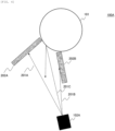
- Fig. 2 illustrates the test sample reading device 100 viewed from above
- Fig. 3 illustrates the test sample reading device 100 viewed from the side-surface side.
- the barcode reader 102A when defining the normal vector 105A perpendicular to a tangent 106 at a point where the test sample 101 and the optical axis 104A intersect, the barcode reader 102A is arranged so that the optical axis 104A of the irradiating light is inclined in a horizontal direction at an angle greater than 0° in absolute value with respect to the normal vector 105A of the test surface on which the barcode 107 of the test sample 101 is provided.
- the barcode reader 102A is arranged so that an angle between the optical axis 104A and the normal vector 105A is greater than 0° and equal to or less than 20° in the horizontal direction, more preferably 10°, and the barcode reader 102A is arranged so that the optical axis 104A and normal vector 105A on a surface of the barcode 107 are not parallel to each other.
- the barcode reader 102A is arranged so that the angle between the optical axis 104A and the normal vector 105A is greater than 0° and equal to or less than 30° in the vertical direction, more preferably 15° in the vertical direction, and, as in the case of the horizontal direction, the barcode reader 102A is arranged so that the normal vector 105A and optical axis 104A on the surface of the barcode 107 are not parallel to each other.
- the surface of the barcode 107 is irradiated from the lower side in the vertical direction, but the same applies to a configuration in which the surface is irradiated from the upper side. It goes without saying that the angle formed by the optical axis 104A and the normal vector 105A needs to be set within a range of a reading field of view of the barcode reader 102A.
- test sample reading device 100 of Fig. 1 is an example, and is not limited thereto.
- the normal vector 105A perpendicular to the tangent 106 at the point where the test sample 101 and the optical axis 104A of the barcode reader 102A intersect and the normal vector perpendicular to the tangent 106 at the point where the optical axis 104D of the barcode reader 102D intersects with the test sample 101 are common
- the normal vector 105B perpendicular to the tangent 106 at the point where the test sample 101 and the optical axis 104B of the barcode reader 102B intersect and the normal vector perpendicular to the tangent 106 at the point where the optical axis 104E of the barcode reader 102E intersects with the test sample 101 are common
- the number of barcode readers is determined by a sensing range of the barcode readers. What is important is to determine the number of barcode readers so that the sum of sensing ranges of the plurality of barcode readers is larger than the entire circumference 360° of the test sample 101 so that the test sample 101 does not need to be rotated.
- test sample holding ribs can be one or more.
- a user installs the test sample 101 so as to be fit within the test sample holding ribs 103A, 103B, 103C, 103D, 103E, and 103F, and causes the barcode readers 102A, 102B, 102C, 102D, 102E, and 102F to emit light.
- the test sample 101 is grabbed up and taken, and the next test sample 101 is installed. By repeating this, information on the required number of test samples 101 is read.
- the test sample reading device 100 that reads the barcode 107 provided on the test sample 101 according to Example 1 of the present invention described above includes self-luminous barcode readers 102A, 102B, 102C, 102D, 102E, and 102F, and the self-luminous barcode readers 102A, 102B, 102C, 102D, 102E, and 102F are arranged so that irradiating light emitted from the barcode readers 102A, 102B, 102C, 102D, 102E, and 102F entirely covers a surface provided with the barcode 107 and the optical axes 104A, 104B, 104C, 104D, 104E, and 104F of the irradiating light are inclined in the horizontal direction at an angle greater than 0° in absolute value and in the vertical direction at an angle greater than 0° in absolute value with respect to the normal vectors 105A, 105B, and 105C of the test surface of the test sample 101 provided with the barcode
- an irradiation area that is obtained by combining two or more barcode readers 102A, 102B, 102C, 102D, 102E, and 102F entirely covers the surface, two or more optical axes 104A, 104B, 104C, 104D, 104E, and 104F are deviated from all the normal vectors 105A, 105B, and 105C on the test surface, and the respective optical axes 104A, 104B, 104C, 104D, 104E, and 104F are deviated from all other optical axes 104A, 104B, 104C, 104D, 104E, and 104F, and thus the barcode 107 can be detected more reliably and failures in reading due to light emission from other barcode readers 102A, 102B, 102C, 102D, 102E, and 102F can be avoided.
- the test sample 101 has a circular cross section, and further includes the test sample holding ribs 103A, 103B, 103C, 103D, 103E, and 103F that support the side surface of the test sample 101 at at least three points
- the test sample holding ribs 103A, 103B, 103C, 103D, 103E, and 103F are plates parallel to one of the optical axes 104A, 104B, 104C, 104D, 104E, and 104F, and are arranged discretely on the side surface of the test sample 101, so that it is possible to suppress the test sample 101 from wobbling when reading the barcode 107, and to further reduce failures during reading.
- test sample holding ribs 103A, 103B, 103C, 103D, 103E, and 103F it is possible to reliably avoid a decrease in reading efficiency.
- the barcode readers 102A, 102B, 102C, 102D, 102E, and 102F are arranged at equal intervals around the test sample 101 and are arranged so that the angle between the optical axes 104A, 104B, 104C, 104D, 104E, and 104F and the normal vectors 105A, 105B, and 105C is greater than 0° and equal to or less than 20° in the horizontal direction, and greater than 0° and equal to or less than 30° in the vertical direction, and the test sample holding ribs 103A, 103B, 103C, 103D, 103E, and 103F are arranged between the plurality of barcode readers 102A, 102B, 102C, 102D, 102E, and 102F, thereby capable of obtaining the arrangement relationship that allows reflected light reflected by the barcode 107 to more efficiently return to the barcode readers 102A, 102B, 102C, 102D, 102E, and
- Fig. 4 is a diagram illustrating an example of a configuration of the test sample reading device according to Example 2.
- a test sample reading device 100A according to Example 2 illustrated in Fig. 4 has a configuration in which reflection of irradiating light is prevented by test sample holding ribs 202A and 202B.
- the test sample holding ribs 202A and 202B illustrated in Fig. 4 are made of a material or colored member that absorbs irradiating light, and are configured to prevent reflection of irradiating light 201A and 201B. With this, among irradiating light 201A, 201B, and 201C emitted from the barcode reader 102A, the unnecessary irradiating lights 201A and 201B with which portions other than the barcode 107 portion are irradiated are absorbed so that only the diffusely reflected light of the irradiating light 201C directly directed to the test sample 101 is returned to the light receiving part of the barcode reader 102A.
- test sample holding ribs 202A and 202B are preferably made of non-metallic material and black in color.
- test sample holding ribs 202A and 202B have two roles including a role of maintaining the posture of the test sample 101 vertically and a role of preventing the irradiating lights from the plurality of barcode readers 102A, 102B, 102C, 102D, 102E, and 102F from intersecting each other.
- test sample holding ribs 202A and 202B are thin plates so as not to cover the surface of the barcode 107.
- the above conditions can be satisfied by discretely arranging thin plates of about 50 mm in length, 20 mm in width, and 2 mm in thickness around the test sample.
- test sample reading device and the test sample reading method according to Example 2 of the present invention substantially the same effects as those of the test sample reading device and test sample reading method according to Example 1 described above can be obtained.
- test sample holding ribs 202A and 202B are configured to absorb irradiating light, so that unnecessary irradiating light 201A and 201B are cut and only the diffusely reflected light of the irradiating light 201C directly directed to the test sample 101 returns to the light receiving part of the barcode reader 102A. Therefore, the success rate of reading the barcode 107 can be further increased.
- FIGS. 5 and 6 are diagrams illustrating an example of the configuration of the test sample reading device according to Example 3.
- a test sample reading device 100B of Example 3 of this example illustrated in Fig. 5 is configured to read the entire circumference of the test sample 101 on a belt conveyor 301 by four barcode readers 102A, 102B, 102C, and 102D.
- a portion of the belt conveyor 301 that conveys the test sample 101 is provided with an area where the barcode readers 102A, 102B, 102C, and 102D scan the test sample 101 in all directions, and the barcode readers 102A, 102B, 102C, and 102D read information on the test sample 101 located in the area.
- test samples 101 are sequentially conveyed in one direction on the belt conveyor 301.
- the barcode readers 102A, 102B, 102C, and 102D are arranged around the test sample 101 so as to avoid regular reflection. These barcode readers 102A, 102B, 102C, 102D always emit light, the test sample passes through the area where the barcode readers 102A, 102B, 102C, and 102D scan the test sample 101 in all directions while the plurality of test samples 101 are sequentially conveyed on the belt conveyor 301, and reading of the barcode 107 is completed by any one or more of the barcode readers 102A, 102B, 102C, and 102D, and thus, there is no need to stop the belt conveyor 301 during reading, and it is possible to improve conveyance throughput.
- the test sample 101 is sequentially conveyed in one direction by the belt conveyor 301, and a quarter area of the entire circumference of the test sample is read in order from the barcode reader 102D to the barcode reader 102A.
- the barcode reader 102D Immediately before entering the reading range of the barcode reader 102D, all the barcode readers 102A, 102B, 102C, and 102D are made to emit light, and the barcode reader 102D first reads a range of 90° out of the entire circumference. If the barcode 107 is read, the test sample 101 is conveyed as it is, the barcode reader 102C is made to emit light if the barcode 107 is not read, the barcode reader 102B is made to emit if the barcode 107 fails to be read, the barcode reader 102A is made to emit light if the barcode 107 further fails to be read, in order, to read the barcode 107. At the time when the reading of the barcode reader 102A is completed, the reading of the entire circumference of 360° of the test sample 101 is completed.
- test sample reading device and the test sample reading method according to Example 3 of the present invention substantially the same effects as those of the test sample reading device and test sample reading method according to Example 1 described above can be obtained.
- belt conveyors 301, 301A, and 301B that convey the test sample 101 are provided with the area where the barcode readers 102A, 102B, 102C, and 102D scan the test sample 101 in all directions, and the barcode readers 102A, 102B, 102C, and 102D can read the barcode 107 of the test sample 101 being conveyed by reading information about the test sample 101 located in the area and can improve the efficiency of reading.
- the barcode readers 102A, 102B, 102C, and 102D are deviated so that the irradiating light does not overlap and sequentially scanning a portion of a reading area of the barcode 107 in all directions while the test sample 101 is being conveyed, it is possible to prevent reading of the reflected light from the barcode 107 from being obstructed by the irradiating light from other barcode readers 102A, 102B, 102C, and 102D, and it is possible to read the barcode 107 more efficiently.
- the conveyance device is not limited to this, and can be formed into a form such as electromagnetic conveyance or a self-propelled type in which a holder of a test sample moves by itself.
- Fig. 7 is a diagram illustrating an example of a configuration of the test sample reading device according to Example 4.
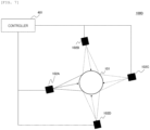
- a test sample reading device 100D of this example illustrated in Fig. 7 controls the light emission timing of a plurality of barcode readers 102A, 102B, 102C, and 102D. Although a case where four barcode readers 102A, 102B, 102C, and 102D are used is described in Fig. 7 , two or more barcode readers can be used.
- a controller 401 illustrated in Fig. 7 is connected to the barcode readers 102A, 102B, 102C, and 102D, and controls the light emission timing so as to emit light at different timings.
- This controller 401 is not particularly limited as long as it is a device capable of communicating with the barcode readers 102A, 102B, 102C, and 102D, such as a PC.
- the controller 401 can end a reading operation, and if the controller 401 fails to read the barcode 107, the controller can select one of the barcode readers 102A, 102B, 102C, and 102D that has not yet emitted light and cause the selected barcode reader to emit light.
- the barcode reader 102A emits light first and successfully reads the barcode 107 affixed to the test sample 101, the remaining barcode readers 102B, 102C, and 102D do not emit light.
- reading by the barcode reader 102A fails, one of the barcode readers 102B, 102C, and 102D is selected and caused to emit light. After that, the barcode readers 102A, 102B, 102C, and 102D repeatedly emit light until the barcode 107 is successfully read. Finally, reading of the barcode 107 is completed by any one of the barcode readers 102A, 102B, 102C, and 102D.
- test sample reading device and the test sample reading method according to Example 4 of the present invention substantially the same effects as those of the test sample reading device and test sample reading method according to Example 1 described above can be obtained.
- reading control can be automated.
- the controller 401 can end the reading operation, and if the reading of the barcode 107 fails, the controller 401 can select one of the barcode readers 102A, 102B, 102C, and 102D that has not yet emitted light and cause the selected barcode reader to emit light, thereby capable of eliminating the influence of the irradiating light from the adjacent barcode readers 102A, 102B, 102C, and 102D during reading, and capable of further increasing the success rate of reading. Further, since the barcode readers 102A, 102B, 102C, and 102D that do not emit light exist in some cases, the effect that wear and tear of the reader can be suppressed can also be obtained.
- FIG. 8 and Fig. 9 are diagrams illustrating an example of a configuration of the test sample reading device according to Example 5.
- a test sample reading device 100E of this example illustrated in Fig. 8 is in a form in which the posture of the test sample 101 is changed.
- a cylindrical shaft of the cylindrical test sample 101 is fixed at a fixed position by test sample holding jigs 501A and 501B so that the barcode 107 can be read in a state where the test sample 101 is horizontally laid down.
- the test sample holding jigs 501A and 501B are made of a material that transmits the irradiating light emitted from the barcode readers 102A, 102B, 102C, and 102D.
- transparent glass may be used as the material that transmits the irradiating light.
- the barcode readers 102A, 102B, 102C, and 102D are arranged so that each of the optical axes 104A, 104B, 104C, and 104D of irradiation axes is not parallel to the normal vector of the side surface of the test sample 101.
- test sample holding ribs such as those used in Example 1 can also be used.
- this is an example of another configuration in the case where the barcode 107 is read in the state where the test sample 101 is horizontally laid down.
- the test sample holding ribs 103A, 103B, and 103C are discretely arranged on the lower side of the test sample 101 so that the test sample 101 does not fall.
- the barcode readers 102B and 102C irradiate the test sample 101 from between the test sample holding ribs 103A, 103B, and 103C.
- the test sample holding ribs 103A, 103B, and 103C are not required on the upper side of the test sample 101, and the upper half of the test sample is irradiated by the barcode readers 102A and 102D.
- test sample reading device and the test sample reading method according to Example 5 of the present invention substantially the same effects as those of the test sample reading device and test sample reading method according to Example 1 described above can be obtained.
- Fig. 10 is a diagram illustrating an example of a configuration of the test sample reading device according to Example 6.
- a test sample reading device 100G of this example illustrated in Fig. 10 has a configuration corresponding to a case where a shape of a test sample 601 is different from that of Example 1 and the like.
- a test sample reading device 100G is configured with the barcode readers 102A, 102B, 102C, and 102D, and L-shaped test sample holding ribs 602A, 602B, 602C, and 602D.
- test sample 601 four corners of the test sample 601 are fixed by the L-shaped test sample holding ribs 602A, 602B, 602C, and 602D.
- the L-shaped test sample holding ribs 602A, 602B, 602C, and 602D prevent the test sample 601 from rotating, and prevent the surface of the barcode 107 from being out of an irradiation range of the barcode readers 102A, 102B, 102C, and 102D.
- the barcode readers 102A, 102B, 102C, and 102D are arranged so that the irradiation optical axes thereof are not perpendicular to the surface of the barcode 107.
- the irradiation optical axes thereof are not perpendicular to the surface of the barcode 107.
- the surface of the barcode 107 is flat like a square, even if the test sample 601 is moved in parallel, the angle between an irradiation optical axis and the surface of the barcode 107 does not change. Therefore, by deviating the irradiation optical axis from the normal vector of the surface of the barcode 107 in advance, it is possible to avoid a decrease in reading accuracy due to regular reflection.
- test sample reading device and the test sample reading method according to Example 6 of the present invention substantially the same effects as those of the test sample reading device and test sample reading method according to Example 1 described above can be obtained.
- Fig. 11 is a diagram illustrating an example of a configuration of the test sample reading device according to Example 7.
- a test sample reading device 100H of this example illustrated in Fig. 11 has a form suitable for reading the test sample 101 conveyed on multi-row belt conveyors 301A and 301B.
- Fig. 11 illustrates a configuration in which the barcode 107 is read while the test sample 101 is conveyed on two horizontal rows of the belt conveyors 301 and 301B.
- the belt conveyors 301A and 301B similar to those in Example 3 are arranged adjacent to each other.
- the barcode readers 102C and 102E located between the belt conveyors 301A and 301B by arranging the respective barcode readers so as to irradiate the test sample 101, in addition to arranging the respective barcode readers so that the optical axes of the irradiating light are inclined in a horizontal direction at an angle greater than 0° in absolute value and in a vertical direction at an angle greater than 0° in absolute value with respect to the normal vectors of the test surface of the test sample 101 provided with the barcode 107, it becomes possible to arrange the barcode readers so as not to interfere with each other's irradiation optical axes.
- barcode readers 102A, 102B, 102D, 102F, 102G, and 102H are arranged so that the optical axes of the irradiating light are inclined in the horizontal direction at an angle greater than 0° in absolute value and in the vertical direction at an angle greater than 0° in absolute value with respect to the normal vector of the test surface of the test sample 101 provided with the barcode 107.
- the configuration is not limited to a configuration of two horizontal rows, and a multi-row configuration of three or more rows can be realized by increasing the number of belt conveyors.
- test sample reading device and the test sample reading method according to Example 7 of the present invention substantially the same effects as those of the test sample reading device and the test sample reading method according to Example 1 described above can be obtained.
- the present invention is not limited to the examples described above, and includes various modifications.
- the examples described above have been described in detail to describe the present invention in an easy-to-understand manner, and the present invention is not necessarily limited to those having all the configurations described.
- a part of a configuration of a certain example can be replaced with a configuration of another example.
- the configuration of another example can be added to the configuration of the certain example.
- other configurations may be added to, deleted from, or replaced with a part of the configuration of each example.
Landscapes
- Physics & Mathematics (AREA)
- Engineering & Computer Science (AREA)
- General Physics & Mathematics (AREA)
- Electromagnetism (AREA)
- Health & Medical Sciences (AREA)
- General Health & Medical Sciences (AREA)
- Toxicology (AREA)
- Computer Vision & Pattern Recognition (AREA)
- Artificial Intelligence (AREA)
- Theoretical Computer Science (AREA)
- Life Sciences & Earth Sciences (AREA)
- Chemical & Material Sciences (AREA)
- Analytical Chemistry (AREA)
- Biochemistry (AREA)
- Immunology (AREA)
- Pathology (AREA)
- Automatic Analysis And Handling Materials Therefor (AREA)
Abstract
Description
- The present invention relates to a test sample reading device and a test sample reading method for reading a barcode affixed to a test sample.
- PTL 1 describes that "a conveyance device, which is configured to hold and convey a container having a barcode label in an automated system in an in vitro diagnostics environment where a plurality of peripheral readers can read the barcode label", "can consistently capture the container by the double spring arrangement when the container is mounted on the conveyance device and held within the conveyance device during the conveyance operation. Due to the centrally arranged spring housing, an efficient use of space is possible. A mirror image double slot design is provided and the unobstructed space for each slot is complimented, so that a completely unobstructed field of view of the container can be constructed by imaging the same container (sequentially) in both slots and merging the resulting data".
- Further, PTL 2 describes that, as a technique that makes it possible to read a symbol affixed to the circumferential surface of an article without changing the direction of the article on a conveyance line, a plurality of symbol readers for irradiating a container to which a barcode is affixed with laser beams from respectively different directions are included, and by combining respective readable ranges of the respective symbol readers to the container, the entire periphery of a side surface of the container is turned to the readable range, and the barcode is read.
-
- PTL 1:
JP2019-525169A - PTL 2:
JP2013-134512A - A barcode reader is known as a device that reads the barcode affixed to the test sample.
- The test sample is often rod-shaped, such as a test tube, and the barcode is usually affixed along the longitudinal direction of the test sample, but an affixation position of the barcode is not always constant.
- Therefore, there are a plurality of techniques that automatically read the test sample whose affixation position of the barcode is not constant on a conveyance line.
- As an example thereof, the technique described in PTL 1 is known as a technique for holding the container on the conveyance line without blocking a barcode surface. Furthermore, a technique described in PTL 2 is known as a technique for reading the entire circumference of an article by a plurality of barcode readers.
- A conventional barcode reading system is configured to irradiate the barcode with light from the front, and has a problem in that strong regular reflection light returns to the light receiving part to thereby reduce the success rate of reading.
- When reading the barcode affixed to the test sample on the conveyance line, since a barcode surface is a curved surface, an attempt is made to move the test sample to avoid a regular reflection area of the barcode reader, but this has not reached an essential problem solution.
- Furthermore, when reading the barcode on a stationary test sample or when the barcode surface is not the curved surface, there is a problem that regularly reflected light cannot be avoided with a configuration in which it is irradiated with light from the front.
- The present invention provides a test sample reading device and a test sample reading method that can increase the success rate of barcode reading compared with conventional ones.
- The present invention includes a plurality of means for solving the problems described above, and one example thereof is a test sample reading device that reads a barcode provided on a test sample, the test sample reading device including self-luminous barcode readers, in which the self-luminous barcode readers are arranged so that irradiating light emitted from the barcode readers entirely covers a surface provided with the barcode, and optical axes of the irradiating light are inclined in a horizontal direction at an angle greater than 0° in absolute value and in a vertical direction at an angle greater than 0° in absolute value with respect to normal vectors of a test surface of the test sample provided with the barcode.
- According to the present invention, the success rate of barcode reading can be increased compared to the conventional one. Problems, configurations, and effects other than those described above will be made clear by the description of the following examples.
-
- [
Fig. 1] Fig. 1 is a diagram illustrating an example of a configuration of a test sample reading device according to Example 1. - [
Fig. 2] Fig. 2 is a diagram illustrating an example of a configuration of an arrangement of a barcode reader according to Example 1. - [
Fig. 3] Fig. 3 is a diagram illustrating an example of the configuration of the arrangement of the barcode reader according to Example 1. - [
Fig. 4] Fig. 4 is a diagram illustrating an example of a configuration of a test sample reading device according to Example 2. - [
Fig. 5] Fig. 5 is a diagram illustrating an example of a configuration of a test sample reading device according to Example 3. - [
Fig. 6] Fig. 6 is a diagram illustrating another example of the configuration of the test sample reading device according to Example 3. - [
Fig. 7] Fig. 7 is a diagram illustrating an example of a configuration of a test sample reading device according to Example 4. - [
Fig. 8] Fig. 8 is a diagram illustrating an example of a configuration of a test sample reading device according to Example 5. - [
Fig. 9] Fig. 9 is a diagram illustrating another example of the configuration of the test sample reading device according to Example 5. - [
Fig. 10] Fig. 10 is a diagram illustrating an example of a configuration of a test sample reading device according to Example 6. - [
Fig. 11] Fig. 11 is a diagram illustrating an example of a configuration of a test sample reading device according to Example 7. - Examples of the test sample reading device and the test sample reading method of the present invention will be described below with reference to the drawings. However, the present invention should not be construed as being limited to the contents described in Examples shown below. Those skilled in the art will readily understand that a specific configuration of the present invention can be changed within a range not departing from the idea or spirit thereof.
- In the configuration of the invention described below, the same or similar configurations or functions are denoted by the same reference numerals, and redundant descriptions thereof will be omitted.
- The notations such as "first", "second", "third" and the like in this specification are attached to identify constituent elements, and do not necessarily limit the number or order thereof.
- A position, size, shape, range, and the like of each configuration shown in the drawings, and the like may not represent an actual position, size, shape, range, and the like in order to facilitate understanding of the invention. Therefore, in the present invention, those are not limited to the position, size, shape, range, and the like disclosed in the drawings and the like.
- Example 1 of the test sample reading device and the test sample reading method of the present invention will be described using
Figs. 1 to 3 .Fig. 1 is a diagram illustrating an example of a configuration of the test sample reading device according to Example 1, andFigs. 2 and3 are diagrams illustrating an example of a configuration of an arrangement of a barcode reader according to Example 1. - A test
sample reading device 100 illustrated inFig. 1 is a device for reading abarcode 107 provided on atest sample 101 having a circular cross section, and is configured withbarcode readers sample holding ribs - The
barcode readers test sample 101. - More specifically, six
barcode readers test sample 101. - Further, all of
optical axes barcode readers normal vectors barcode 107 is affixed), and the respectiveoptical axes optical axes - Furthermore, irradiating light emitted from the
barcode readers test sample 101 on which thebarcode 107 is provided, and thebarcode 107 can be scanned by any one or more of thebarcode readers - The test
sample holding ribs test sample 101 at at least three points (six points inFig. 1 ), and are arranged discretely with respect to the side surface of thetest sample 101. Further, the testsample holding ribs barcode readers - Furthermore, in this example, the test
sample holding ribs optical axes optical axes - Therefore, the test
sample holding ribs test sample 101. -
Figs. 2 and3 are diagrams illustrating an example of an arrangement of the barcode readers according to Example 1.Fig. 2 illustrates the testsample reading device 100 viewed from above, andFig. 3 illustrates the testsample reading device 100 viewed from the side-surface side. - As illustrated in
Fig. 2 , it is assumed that, regarding thebarcode reader 102A, when defining thenormal vector 105A perpendicular to atangent 106 at a point where thetest sample 101 and theoptical axis 104A intersect, thebarcode reader 102A is arranged so that theoptical axis 104A of the irradiating light is inclined in a horizontal direction at an angle greater than 0° in absolute value with respect to thenormal vector 105A of the test surface on which thebarcode 107 of thetest sample 101 is provided. - More specifically, the
barcode reader 102A is arranged so that an angle between theoptical axis 104A and thenormal vector 105A is greater than 0° and equal to or less than 20° in the horizontal direction, more preferably 10°, and thebarcode reader 102A is arranged so that theoptical axis 104A andnormal vector 105A on a surface of thebarcode 107 are not parallel to each other. - As illustrated in
Fig. 3 , since thebarcode 107 is affixed along the longitudinal direction of thetest sample 101, it is assumed that arrangement is performed so that theoptical axis 104A of the irradiating light is inclined in a vertical direction at an angle greater than 0° in absolute value with respect to thenormal vector 105A of the test surface of thetest sample 101 on which thebarcode 107 is provided. - More specifically, the
barcode reader 102A is arranged so that the angle between theoptical axis 104A and thenormal vector 105A is greater than 0° and equal to or less than 30° in the vertical direction, more preferably 15° in the vertical direction, and, as in the case of the horizontal direction, thebarcode reader 102A is arranged so that thenormal vector 105A andoptical axis 104A on the surface of thebarcode 107 are not parallel to each other. - In
Fig. 3 , the surface of thebarcode 107 is irradiated from the lower side in the vertical direction, but the same applies to a configuration in which the surface is irradiated from the upper side. It goes without saying that the angle formed by theoptical axis 104A and thenormal vector 105A needs to be set within a range of a reading field of view of thebarcode reader 102A. - The arrangement relationships in
Figs. 2 and3 are the same for allother barcode readers - Note that the configuration of the test
sample reading device 100 ofFig. 1 is an example, and is not limited thereto. - In
Fig. 1 , since the sixbarcode readers test sample 101, thenormal vector 105A perpendicular to the tangent 106 at the point where thetest sample 101 and theoptical axis 104A of thebarcode reader 102A intersect and the normal vector perpendicular to the tangent 106 at the point where theoptical axis 104D of thebarcode reader 102D intersects with thetest sample 101 are common, thenormal vector 105B perpendicular to the tangent 106 at the point where thetest sample 101 and theoptical axis 104B of thebarcode reader 102B intersect and the normal vector perpendicular to the tangent 106 at the point where theoptical axis 104E of thebarcode reader 102E intersects with thetest sample 101 are common, and thenormal vector 105C perpendicular to the tangent 106 at the point where thetest sample 101 and theoptical axis 104C of thebarcode reader 102C intersect and the normal vector perpendicular to the tangent 106 at the point where theoptical axis 104F of thebarcode reader 102F intersects with thetest sample 101 are common, but they are not limited to such arrangement and can be changed appropriately. - For example, the number of barcode readers is determined by a sensing range of the barcode readers. What is important is to determine the number of barcode readers so that the sum of sensing ranges of the plurality of barcode readers is larger than the entire circumference 360° of the
test sample 101 so that thetest sample 101 does not need to be rotated. - When the cross section of a test tube like the
test sample 101 ofFig. 1 is circular, since the barcode surface is a curved surface, there is a concern that the barcode surface is distorted when viewed from the barcode reader near the boundary between adjacent irradiating lights, which results in a decrease in reading accuracy. Therefore, it is desirable to arrange more barcode readers than the minimum number required and partially overlap the sensing ranges to achieve stable reading. - Further, although it is desirable to arrange the same number of test sample holding ribs as the number of barcode readers, there is no particular limitation, and the number of test sample holding ribs can be one or more.
- A user installs the
test sample 101 so as to be fit within the testsample holding ribs barcode readers barcode readers test sample 101 is grabbed up and taken, and thenext test sample 101 is installed. By repeating this, information on the required number oftest samples 101 is read. - Next, the effects of this example will be described.
- The test
sample reading device 100 that reads thebarcode 107 provided on thetest sample 101 according to Example 1 of the present invention described above includes self-luminous barcode readers luminous barcode readers barcode readers barcode 107 and theoptical axes normal vectors test sample 101 provided with thebarcode 107. - With this, since it is possible to avoid regularly reflected light from returning to light receiving parts of the
barcode readers barcode 107, it is possible to achieve more stable barcode reading compared with a conventional one. - Further, an irradiation area that is obtained by combining two or
more barcode readers optical axes normal vectors optical axes optical axes barcode 107 can be detected more reliably and failures in reading due to light emission fromother barcode readers - Furthermore, the
test sample 101 has a circular cross section, and further includes the testsample holding ribs test sample 101 at at least three points, the testsample holding ribs optical axes test sample 101, so that it is possible to suppress thetest sample 101 from wobbling when reading thebarcode 107, and to further reduce failures during reading. Further, it is possible to prevent the irradiating light from being blocked by the testsample holding ribs - Further, the
barcode readers test sample 101 and are arranged so that the angle between theoptical axes normal vectors sample holding ribs barcode readers barcode 107 to more efficiently return to thebarcode readers barcode 107 with even higher accuracy. - A test sample reading device and a test sample reading method according to Example 2 of the present invention will be described using
Fig. 4. Fig. 4 is a diagram illustrating an example of a configuration of the test sample reading device according to Example 2. - A test
sample reading device 100A according to Example 2 illustrated inFig. 4 has a configuration in which reflection of irradiating light is prevented by testsample holding ribs - The test
sample holding ribs Fig. 4 are made of a material or colored member that absorbs irradiating light, and are configured to prevent reflection of irradiating light 201A and 201B. With this, among irradiating light 201A, 201B, and 201C emitted from thebarcode reader 102A, theunnecessary irradiating lights barcode 107 portion are irradiated are absorbed so that only the diffusely reflected light of the irradiating light 201C directly directed to thetest sample 101 is returned to the light receiving part of thebarcode reader 102A. - Examples of the test
sample holding ribs - Here, the test
sample holding ribs test sample 101 vertically and a role of preventing the irradiating lights from the plurality ofbarcode readers - Therefore, it is desirable that the test
sample holding ribs barcode 107. For example, the above conditions can be satisfied by discretely arranging thin plates of about 50 mm in length, 20 mm in width, and 2 mm in thickness around the test sample. - The other configurations and operations are substantially the same as those of the test sample reading device and the test sample reading method according to Example 1 described above, and the details thereof will be omitted.
- Also, in the test sample reading device and the test sample reading method according to Example 2 of the present invention, substantially the same effects as those of the test sample reading device and test sample reading method according to Example 1 described above can be obtained.
- Further, the test
sample holding ribs test sample 101 returns to the light receiving part of thebarcode reader 102A. Therefore, the success rate of reading thebarcode 107 can be further increased. - A test sample reading device and a test sample reading method according to Example 3 of the present invention will be described using
Figs. 5 and 6. Figs. 5 and 6 are diagrams illustrating an example of the configuration of the test sample reading device according to Example 3. - A test
sample reading device 100B of Example 3 of this example illustrated inFig. 5 is configured to read the entire circumference of thetest sample 101 on abelt conveyor 301 by fourbarcode readers - More specifically, as illustrated in
Fig. 5 , it is configured such that a portion of thebelt conveyor 301 that conveys thetest sample 101 is provided with an area where thebarcode readers test sample 101 in all directions, and thebarcode readers test sample 101 located in the area. - On the
belt conveyor 301, thetest samples 101 are sequentially conveyed in one direction on thebelt conveyor 301. - To describe an example of reading the barcode of the
test sample 101, thebarcode readers test sample 101 so as to avoid regular reflection. Thesebarcode readers barcode readers test sample 101 in all directions while the plurality oftest samples 101 are sequentially conveyed on thebelt conveyor 301, and reading of thebarcode 107 is completed by any one or more of thebarcode readers belt conveyor 301 during reading, and it is possible to improve conveyance throughput. - Further, it is possible to adopt a configuration in which, as in a test sample reading device 100C illustrated in
Fig. 6 , fourbarcode readers barcode readers test sample 101 is sequentially scanned in portions of all directions while thetest sample 101 is being conveyed. - In a conveyance line to which the test sample reading device 100C is applied, the
test sample 101 is sequentially conveyed in one direction by thebelt conveyor 301, and a quarter area of the entire circumference of the test sample is read in order from thebarcode reader 102D to thebarcode reader 102A. - Immediately before entering the reading range of the
barcode reader 102D, all thebarcode readers barcode reader 102D first reads a range of 90° out of the entire circumference. If thebarcode 107 is read, thetest sample 101 is conveyed as it is, thebarcode reader 102C is made to emit light if thebarcode 107 is not read, thebarcode reader 102B is made to emit if thebarcode 107 fails to be read, thebarcode reader 102A is made to emit light if thebarcode 107 further fails to be read, in order, to read thebarcode 107. At the time when the reading of thebarcode reader 102A is completed, the reading of the entire circumference of 360° of thetest sample 101 is completed. - Instead of causing all the
barcode readers corresponding barcode readers test sample 101 has been conveyed to the reading area by a sensor that detects thetest sample 101 and the like can be adopted. - The other configurations and operations are substantially the same as those of the test sample reading device and the test sample reading method according to Example 1 described above, and the details thereof will be omitted.
- Also, in the test sample reading device and the test sample reading method according to Example 3 of the present invention, substantially the same effects as those of the test sample reading device and test sample reading method according to Example 1 described above can be obtained.
- Further,
belt conveyors test sample 101 are provided with the area where thebarcode readers test sample 101 in all directions, and thebarcode readers barcode 107 of thetest sample 101 being conveyed by reading information about thetest sample 101 located in the area and can improve the efficiency of reading. - Furthermore, by arranging the
barcode readers barcode 107 in all directions while thetest sample 101 is being conveyed, it is possible to prevent reading of the reflected light from thebarcode 107 from being obstructed by the irradiating light fromother barcode readers barcode 107 more efficiently. - Note that although a form in which the
belt conveyor 301 is used as a conveyance device is described, the conveyance device is not limited to this, and can be formed into a form such as electromagnetic conveyance or a self-propelled type in which a holder of a test sample moves by itself. - A test sample reading device and a test sample reading method according to Example 4 of the present invention will be described using
Fig. 7. Fig. 7 is a diagram illustrating an example of a configuration of the test sample reading device according to Example 4. - A test
sample reading device 100D of this example illustrated inFig. 7 controls the light emission timing of a plurality ofbarcode readers barcode readers Fig. 7 , two or more barcode readers can be used. - A
controller 401 illustrated inFig. 7 is connected to thebarcode readers controller 401 is not particularly limited as long as it is a device capable of communicating with thebarcode readers - If the
controller 401 successfully read thebarcode 107, the controller can end a reading operation, and if thecontroller 401 fails to read thebarcode 107, the controller can select one of thebarcode readers - For example, if the
barcode reader 102A emits light first and successfully reads thebarcode 107 affixed to thetest sample 101, the remainingbarcode readers - If reading by the
barcode reader 102A fails, one of thebarcode readers barcode readers barcode 107 is successfully read. Finally, reading of thebarcode 107 is completed by any one of thebarcode readers - Note that if reading by all the
barcode readers barcode readers - The other configurations and operations are substantially the same as those of the test sample reading device and the test sample reading method according to Example 1 described above, and the details thereof will be omitted.
- Also, in the test sample reading device and the test sample reading method according to Example 4 of the present invention, substantially the same effects as those of the test sample reading device and test sample reading method according to Example 1 described above can be obtained.
- Further, by further providing the
controller 401 that causes thebarcode readers - Furthermore, if reading of the
barcode 107 is successful, thecontroller 401 can end the reading operation, and if the reading of thebarcode 107 fails, thecontroller 401 can select one of thebarcode readers adjacent barcode readers barcode readers - A test sample reading device and a test sample reading method according to Example 5 of the present invention will be described using
Figs. 8 and9 .Fig. 8 andFig. 9 are diagrams illustrating an example of a configuration of the test sample reading device according to Example 5. - A test
sample reading device 100E of this example illustrated inFig. 8 is in a form in which the posture of thetest sample 101 is changed. - As illustrated in
Fig. 8 , a cylindrical shaft of thecylindrical test sample 101 is fixed at a fixed position by testsample holding jigs barcode 107 can be read in a state where thetest sample 101 is horizontally laid down. - The test
sample holding jigs barcode readers - Even in such a case, the
barcode readers optical axes test sample 101. - Further, the test sample holding ribs such as those used in Example 1 can also be used. As in a test
sample reading device 100F illustrated inFig. 9 , this is an example of another configuration in the case where thebarcode 107 is read in the state where thetest sample 101 is horizontally laid down. - As illustrated in
Fig. 9 , the testsample holding ribs test sample 101 so that thetest sample 101 does not fall. Thebarcode readers test sample 101 from between the testsample holding ribs sample holding ribs test sample 101, and the upper half of the test sample is irradiated by thebarcode readers - The other configurations and operations are substantially the same as those of the test sample reading device and the test sample reading method according to Example 1 described above, and the details thereof will be omitted.
- Also, in the test sample reading device and the test sample reading method according to Example 5 of the present invention, substantially the same effects as those of the test sample reading device and test sample reading method according to Example 1 described above can be obtained.
- A test sample reading device and a test sample reading method according to Example 6 of the present invention will be described using
Fig. 10. Fig. 10 is a diagram illustrating an example of a configuration of the test sample reading device according to Example 6. - A test
sample reading device 100G of this example illustrated inFig. 10 has a configuration corresponding to a case where a shape of atest sample 601 is different from that of Example 1 and the like. - As illustrated in
Fig. 10 , assuming that a place to which thebarcode 107 of atest sample 601 having a square cross section is attached is one or more of four side surfaces, a testsample reading device 100G is configured with thebarcode readers sample holding ribs - In this case, four corners of the
test sample 601 are fixed by the L-shaped testsample holding ribs sample holding ribs test sample 601 from rotating, and prevent the surface of thebarcode 107 from being out of an irradiation range of thebarcode readers - Further, the
barcode readers barcode 107. For example, when applied to the conveyance line of Example 3, when the surface of thebarcode 107 is flat like a square, even if thetest sample 601 is moved in parallel, the angle between an irradiation optical axis and the surface of thebarcode 107 does not change. Therefore, by deviating the irradiation optical axis from the normal vector of the surface of thebarcode 107 in advance, it is possible to avoid a decrease in reading accuracy due to regular reflection. - The other configurations and operations are substantially the same as those of the test sample reading device and the test sample reading method according to Example 1 described above, and the details thereof will be omitted.
- Also, in the test sample reading device and the test sample reading method according to Example 6 of the present invention, substantially the same effects as those of the test sample reading device and test sample reading method according to Example 1 described above can be obtained.
- A test sample reading device and a test sample reading method according to Example 7 of the present invention will be described using
Fig. 11. Fig. 11 is a diagram illustrating an example of a configuration of the test sample reading device according to Example 7. - A test
sample reading device 100H of this example illustrated inFig. 11 has a form suitable for reading thetest sample 101 conveyed onmulti-row belt conveyors -
Fig. 11 illustrates a configuration in which thebarcode 107 is read while thetest sample 101 is conveyed on two horizontal rows of thebelt conveyors - As illustrated in
Fig. 11 , thebelt conveyors barcode readers belt conveyors test sample 101, in addition to arranging the respective barcode readers so that the optical axes of the irradiating light are inclined in a horizontal direction at an angle greater than 0° in absolute value and in a vertical direction at an angle greater than 0° in absolute value with respect to the normal vectors of the test surface of thetest sample 101 provided with thebarcode 107, it becomes possible to arrange the barcode readers so as not to interfere with each other's irradiation optical axes. -
Other barcode readers test sample 101 provided with thebarcode 107. - The configuration is not limited to a configuration of two horizontal rows, and a multi-row configuration of three or more rows can be realized by increasing the number of belt conveyors.
- The other configurations and operations are substantially the same as those of the test sample reading device and the test sample reading method according to Example 1 described above, and the details thereof will be omitted.
- Also, in the test sample reading device and the test sample reading method according to Example 7 of the present invention, substantially the same effects as those of the test sample reading device and the test sample reading method according to Example 1 described above can be obtained.
- The present invention is not limited to the examples described above, and includes various modifications. The examples described above have been described in detail to describe the present invention in an easy-to-understand manner, and the present invention is not necessarily limited to those having all the configurations described.
- Further, a part of a configuration of a certain example can be replaced with a configuration of another example. Furthermore, the configuration of another example can be added to the configuration of the certain example. Furthermore, other configurations may be added to, deleted from, or replaced with a part of the configuration of each example.
-
- 100, 100A, 100B, 100C, 100D, 100E, 100F, 100G, 100H: test sample reading device
- 101: test sample (circular in cross section)
- 102A, 102B, 102C, 102D, 102E, 102F, 102G, 102H: barcode reader
- 103A, 103B, 103C, 103D, 103E, 103F, 202A, 202B: test sample holding rib
- 104A, 104B, 104C, 104D, 104E, 104F: optical axis
- 105A, 105B, 105C: normal vector
- 106: tangent
- 107: barcode
- 201A, 201B, 201C: irradiating light
- 301, 301A, 301B: belt conveyor (conveyance device)
- 401: controller
- 501A, 501B: test sample holding jig
- 601: test sample (square in cross section)
- 602A, 602B, 602C, 602D: L-shaped test sample holding rib
Claims (11)
- A test sample reading device that reads a barcode provided on a test sample, comprising:self-luminous barcode readers, whereinthe barcode readers are arranged so thatirradiating light emitted from the barcode readers entirely covers a surface provided with the barcode andoptical axes of the irradiating light are inclined in a horizontal direction at an angle greater than 0° in absolute value and in a vertical direction at an angle greater than 0° in absolute value with respect to normal vectors of a test surface of the test sample provided with the barcode.
- The test sample reading device according to claim 1, whereinthe test sample reading device comprises two or more of the barcode readers,the two or more barcode readers are arranged so that,an irradiation area obtained by combining the two or more of the barcode readers entirely covers the surface, andthe two or more optical axes are deviated from all normal vectors of the test surface, andeach of the optical axes is deviated from all the others of the optical axes.
- The test sample reading device according to claim 2, whereinthe test sample has a circular cross section,the test sample reading device further comprises ribs that support a side surface of the test sample at at least three points,the ribsare plates parallel to one of the optical axes, andare discretely arranged with respect to the side surface of the test sample.
- The test sample reading device according to claim 3, whereinthe barcode readersare arranged at equal intervals around the test sample, andare arranged so that an angle between the optical axis and the normal vector is greater than 0° and equal to or less than 20° in the horizontal direction, and greater than 0° and equal to or less than 30° in the vertical direction, andthe ribs are arranged between the plurality of barcode readers.
- The test sample reading device according to claim 4, whereinthe test sample reading device comprises six of the barcode readers,the six barcode readersare arranged at 60° intervals around the test sample, andarranged so that the angle between the optical axis and the normal vector is 10° in the horizontal direction and 15° in the vertical direction.
- The test sample reading device according to claim 3, wherein
the ribs are configured to absorb the irradiating light. - The test sample reading device according to claim 2, whereina conveyance device that conveys the test sample is provided with an area where the barcode readers scan the test sample in all directions, andthe barcode readers read information on the test sample located in the area.
- The test sample reading device according to claim 7, wherein
the area is configured by arranging the barcode readers to be deviated so that the irradiating light does not overlap, and sequentially scan the test sample in portions of all directions during the conveyance of the test sample. - The test sample reading device according to claim 2, further comprising:
a controller that causes the barcode readers to emit light at different timings. - The test sample reading device according to claim 9, wherein
if reading of the barcode is successful, the controller ends a reading operation, and if the reading of the barcode fails, the controller selects one of the barcode readers that have not yet emitted light and causes the barcode reader to emit light. - A test sample reading method for reading a barcode, wherein
the barcode is read by a plurality of self-luminous barcode readers arranged so that irradiating light emitted from the self-luminous barcode readers entirely covers a surface provided with the barcode provided on a test sample and optical axes of the irradiating light are inclined in a horizontal direction at an angle greater than 0° in absolute value and in a vertical direction at an angle greater than 0° in absolute value with respect to normal vectors of a test surface of the test sample provided with the barcode.
Applications Claiming Priority (2)
| Application Number | Priority Date | Filing Date | Title |
|---|---|---|---|
| JP2022053780A JP7725410B2 (en) | 2022-03-29 | 2022-03-29 | Inspection object reading device and inspection object reading method |
| PCT/JP2022/047064 WO2023188610A1 (en) | 2022-03-29 | 2022-12-21 | Test sample reading device and test sample reading method |
Publications (2)
| Publication Number | Publication Date |
|---|---|
| EP4459499A1 true EP4459499A1 (en) | 2024-11-06 |
| EP4459499A4 EP4459499A4 (en) | 2026-02-11 |
Family
ID=88200081
Family Applications (1)
| Application Number | Title | Priority Date | Filing Date |
|---|---|---|---|
| EP22935737.1A Pending EP4459499A4 (en) | 2022-03-29 | 2022-12-21 | DEVICE AND METHOD FOR READING TEST SAMPLES |
Country Status (5)
| Country | Link |
|---|---|
| US (1) | US12626080B2 (en) |
| EP (1) | EP4459499A4 (en) |
| JP (1) | JP7725410B2 (en) |
| CN (1) | CN118786433A (en) |
| WO (1) | WO2023188610A1 (en) |
Family Cites Families (20)
| Publication number | Priority date | Publication date | Assignee | Title |
|---|---|---|---|---|
| JPS52133719A (en) * | 1976-04-30 | 1977-11-09 | Nippon Denso Co Ltd | Information reader for mov ing object |
| JPS56121182A (en) * | 1980-02-28 | 1981-09-22 | Daifuku Co Ltd | Information read-in method from carried object |
| JP2565195Y2 (en) * | 1991-09-09 | 1998-03-11 | オムロン株式会社 | Optical reader |
| JP3403815B2 (en) * | 1994-07-08 | 2003-05-06 | アロカ株式会社 | Barcode reading method |
| JP2793571B2 (en) | 1996-07-19 | 1998-09-03 | 日本電気エンジニアリング株式会社 | Barcode reader |
| JP4132645B2 (en) | 2000-11-13 | 2008-08-13 | 日本電子株式会社 | Bar code reader |
| JP4098272B2 (en) * | 2004-04-26 | 2008-06-11 | 株式会社アイディエス | Bar code reader for test tubes |
| JP2005338938A (en) | 2004-05-24 | 2005-12-08 | Tsubakimoto Chain Co | Bar code reading device for drug development |
| JP2006133065A (en) | 2004-11-05 | 2006-05-25 | Nst:Kk | Test tube bar code reading method |
| US9734376B2 (en) * | 2007-11-13 | 2017-08-15 | Cognex Corporation | System and method for reading patterns using multiple image frames |
| ES2443941T3 (en) * | 2008-09-15 | 2014-02-21 | Frewitt Printing Sa | Device and reading procedure for marking codes on receptacles |
| JP5872209B2 (en) * | 2011-08-26 | 2016-03-01 | シスメックス株式会社 | Sample analyzer |
| JP5794692B2 (en) | 2011-12-24 | 2015-10-14 | ニッカウヰスキー株式会社 | Optical symbol reader |
| DE102013210287A1 (en) * | 2013-06-04 | 2014-12-04 | Siemens Aktiengesellschaft | Carrier device with bar code reader |
| EP3488246B1 (en) | 2016-07-21 | 2021-09-29 | Siemens Healthcare Diagnostics Inc. | Puck top tube carrier construction |
| JP6414915B1 (en) | 2017-07-06 | 2018-10-31 | Necプラットフォームズ株式会社 | Bar code reader and control method thereof |
| WO2020003359A1 (en) | 2018-06-25 | 2020-01-02 | 株式会社Fuji | Optical mark reader and electronic equipment production apparatus provided with same |
| WO2020061368A1 (en) | 2018-09-20 | 2020-03-26 | Siemens Healthcare Diagnostics Inc. | Visualization analysis apparatus and visual learning methods |
| JP2025121182A (en) | 2024-02-06 | 2025-08-19 | ジェックス株式会社 | Small animal table |
| US20250276575A1 (en) | 2024-03-01 | 2025-09-04 | Vanair Manufacturing, Inc. | Multi-component auxiliary power system and work vehicle |
-
2022
- 2022-03-29 JP JP2022053780A patent/JP7725410B2/en active Active
- 2022-12-21 US US18/837,781 patent/US12626080B2/en active Active
- 2022-12-21 WO PCT/JP2022/047064 patent/WO2023188610A1/en not_active Ceased
- 2022-12-21 CN CN202280092663.3A patent/CN118786433A/en active Pending
- 2022-12-21 EP EP22935737.1A patent/EP4459499A4/en active Pending
Also Published As
| Publication number | Publication date |
|---|---|
| JP2023146550A (en) | 2023-10-12 |
| JP7725410B2 (en) | 2025-08-19 |
| US20250148239A1 (en) | 2025-05-08 |
| WO2023188610A1 (en) | 2023-10-05 |
| CN118786433A (en) | 2024-10-15 |
| EP4459499A4 (en) | 2026-02-11 |
| US12626080B2 (en) | 2026-05-12 |
Similar Documents
| Publication | Publication Date | Title |
|---|---|---|
| JP7034919B2 (en) | Material handling equipment with transport vehicles | |
| ES2952517T3 (en) | Robotic systems and methods for identifying and processing various objects | |
| US9373017B2 (en) | Scanning system | |
| EP2874924B1 (en) | Portal data reader indicator light control | |
| US8448866B2 (en) | Analyte disposable means and device for reading information | |
| CN106865085B (en) | Article conveying apparatus | |
| GB2569845A (en) | Code reading device and code reading method | |
| EP3118786A1 (en) | System for identification and location of goods in a distribution centre | |
| JP2000306086A (en) | Object detection method | |
| US10837975B2 (en) | Automatic analyzing apparatus, reagent container stock apparatus, and specifying method | |
| US20130175342A1 (en) | Sample information detection apparatus and sample information detection method | |
| JP7076032B2 (en) | Image acquisition device and image acquisition method | |
| EP1873682A2 (en) | System and method for obtaining information from objects provided with bar codes and RFID tags | |
| US8757494B2 (en) | Illumination system in imaging scanner | |
| US12626080B2 (en) | Test sample reading device and test sample reading method | |
| US8752767B2 (en) | Illumination system with prism for use in imaging scanner | |
| KR102911875B1 (en) | Handler | |
| US12167117B1 (en) | Method to detect and optimize for scan approach path | |
| US11940562B2 (en) | Sensor apparatus, article display shelf, and production management system | |
| JP6370955B1 (en) | Code reader | |
| US12232075B2 (en) | System and method for automated and dynamic location tracking | |
| US9507989B2 (en) | Decoding barcode using smart linear picklist | |
| JP2016162472A (en) | Library device, storage device and control program | |
| US7152797B1 (en) | Apparatus and method for reading embedded indicia | |
| JP2019016130A (en) | Bar code reader and control method thereof |
Legal Events
| Date | Code | Title | Description |
|---|---|---|---|
| STAA | Information on the status of an ep patent application or granted ep patent |
Free format text: STATUS: THE INTERNATIONAL PUBLICATION HAS BEEN MADE |
|
| PUAI | Public reference made under article 153(3) epc to a published international application that has entered the european phase |
Free format text: ORIGINAL CODE: 0009012 |
|
| STAA | Information on the status of an ep patent application or granted ep patent |
Free format text: STATUS: REQUEST FOR EXAMINATION WAS MADE |
|
| 17P | Request for examination filed |
Effective date: 20240801 |
|
| AK | Designated contracting states |
Kind code of ref document: A1 Designated state(s): AL AT BE BG CH CY CZ DE DK EE ES FI FR GB GR HR HU IE IS IT LI LT LU LV MC ME MK MT NL NO PL PT RO RS SE SI SK SM TR |
|
| DAV | Request for validation of the european patent (deleted) | ||
| DAX | Request for extension of the european patent (deleted) | ||
| A4 | Supplementary search report drawn up and despatched |
Effective date: 20260109 |
|
| RIC1 | Information provided on ipc code assigned before grant |
Ipc: G06K 7/10 20060101AFI20260102BHEP Ipc: G01N 35/02 20060101ALI20260102BHEP Ipc: G01N 35/00 20060101ALI20260102BHEP |
|
| GRAP | Despatch of communication of intention to grant a patent |
Free format text: ORIGINAL CODE: EPIDOSNIGR1 |
|
| STAA | Information on the status of an ep patent application or granted ep patent |
Free format text: STATUS: GRANT OF PATENT IS INTENDED |