EP4459440A1 - Input device and operated member - Google Patents
Input device and operated member Download PDFInfo
- Publication number
- EP4459440A1 EP4459440A1 EP22915885.2A EP22915885A EP4459440A1 EP 4459440 A1 EP4459440 A1 EP 4459440A1 EP 22915885 A EP22915885 A EP 22915885A EP 4459440 A1 EP4459440 A1 EP 4459440A1
- Authority
- EP
- European Patent Office
- Prior art keywords
- input device
- supporting member
- projecting
- axis
- stick
- Prior art date
- Legal status (The legal status is an assumption and is not a legal conclusion. Google has not performed a legal analysis and makes no representation as to the accuracy of the status listed.)
- Pending
Links
Images












Classifications
-
- G—PHYSICS
- G06—COMPUTING OR CALCULATING; COUNTING
- G06F—ELECTRIC DIGITAL DATA PROCESSING
- G06F3/00—Input arrangements for transferring data to be processed into a form capable of being handled by the computer; Output arrangements for transferring data from processing unit to output unit, e.g. interface arrangements
- G06F3/01—Input arrangements or combined input and output arrangements for interaction between user and computer
- G06F3/02—Input arrangements using manually operated switches, e.g. using keyboards or dials
-
- A—HUMAN NECESSITIES
- A63—SPORTS; GAMES; AMUSEMENTS
- A63F—CARD, BOARD, OR ROULETTE GAMES; INDOOR GAMES USING SMALL MOVING PLAYING BODIES; VIDEO GAMES; GAMES NOT OTHERWISE PROVIDED FOR
- A63F13/00—Video games, i.e. games using an electronically generated display having two or more dimensions
- A63F13/20—Input arrangements for video game devices
- A63F13/24—Constructional details thereof, e.g. game controllers with detachable joystick handles
-
- A—HUMAN NECESSITIES
- A63—SPORTS; GAMES; AMUSEMENTS
- A63F—CARD, BOARD, OR ROULETTE GAMES; INDOOR GAMES USING SMALL MOVING PLAYING BODIES; VIDEO GAMES; GAMES NOT OTHERWISE PROVIDED FOR
- A63F13/00—Video games, i.e. games using an electronically generated display having two or more dimensions
- A63F13/90—Constructional details or arrangements of video game devices not provided for in groups A63F13/20 or A63F13/25, e.g. housing, wiring, connections or cabinets
- A63F13/98—Accessories, i.e. detachable arrangements optional for the use of the video game device, e.g. grip supports of game controllers
-
- G—PHYSICS
- G06—COMPUTING OR CALCULATING; COUNTING
- G06F—ELECTRIC DIGITAL DATA PROCESSING
- G06F3/00—Input arrangements for transferring data to be processed into a form capable of being handled by the computer; Output arrangements for transferring data from processing unit to output unit, e.g. interface arrangements
- G06F3/01—Input arrangements or combined input and output arrangements for interaction between user and computer
- G06F3/03—Arrangements for converting the position or the displacement of a member into a coded form
- G06F3/033—Pointing devices displaced or positioned by the user, e.g. mice, trackballs, pens or joysticks; Accessories therefor
- G06F3/0338—Pointing devices displaced or positioned by the user, e.g. mice, trackballs, pens or joysticks; Accessories therefor with detection of limited linear or angular displacement of an operating part of the device from a neutral position, e.g. isotonic or isometric joysticks
-
- G—PHYSICS
- G06—COMPUTING OR CALCULATING; COUNTING
- G06F—ELECTRIC DIGITAL DATA PROCESSING
- G06F3/00—Input arrangements for transferring data to be processed into a form capable of being handled by the computer; Output arrangements for transferring data from processing unit to output unit, e.g. interface arrangements
- G06F3/01—Input arrangements or combined input and output arrangements for interaction between user and computer
- G06F3/03—Arrangements for converting the position or the displacement of a member into a coded form
- G06F3/033—Pointing devices displaced or positioned by the user, e.g. mice, trackballs, pens or joysticks; Accessories therefor
- G06F3/0354—Pointing devices displaced or positioned by the user, e.g. mice, trackballs, pens or joysticks; Accessories therefor with detection of two-dimensional [2D] relative movements between the device, or an operating part thereof, and a plane or surface, e.g. 2D mice, trackballs, pens or pucks
-
- G—PHYSICS
- G06—COMPUTING OR CALCULATING; COUNTING
- G06F—ELECTRIC DIGITAL DATA PROCESSING
- G06F3/00—Input arrangements for transferring data to be processed into a form capable of being handled by the computer; Output arrangements for transferring data from processing unit to output unit, e.g. interface arrangements
- G06F3/01—Input arrangements or combined input and output arrangements for interaction between user and computer
- G06F3/03—Arrangements for converting the position or the displacement of a member into a coded form
- G06F3/033—Pointing devices displaced or positioned by the user, e.g. mice, trackballs, pens or joysticks; Accessories therefor
- G06F3/0362—Pointing devices displaced or positioned by the user, e.g. mice, trackballs, pens or joysticks; Accessories therefor with detection of one-dimensional [1D] translations or rotations of an operating part of the device, e.g. scroll wheels, sliders, knobs, rollers or belts
Definitions
- the present disclosure relates to an input device and an operated member.
- PTL 1 discloses an input device for inputting an instruction of a user to a game device.
- the input device has a left grip and a right grip to be held by the user.
- a plurality of operation buttons and a direction key to be operated by thumbs of the user holding the left and right grips are each arranged on the upper surface of the input device.
- two operation buttons to be operated by middle fingers of the user holding the left and right grips are arranged on the lower surface of the input device.
- An information processing device such as the game device can execute various games (game programs). However, some of these games do not use a part of operated members (operation buttons or the like). Therefore, there is a desire to be able to select the presence or absence of operated members on the input device at the discretion of the user according to the games.
- An input device includes a supporting member having a shaft portion, and configured to move about an axis defined in the shaft portion, a sensor separated from the axis in a first direction orthogonal to the axis, and configured to output a signal according to movement of the supporting member, a housing configured to house the supporting member and the sensor, and an operated member extending in a second direction orthogonal to the axis and intersecting the first direction, and projecting from the housing.
- the operated member is attached to the supporting member so as to move together with the supporting member, and is removable from the supporting member by an operation from an outside of the housing. According to this, the presence or absence of the operated member on the input device can be selected at the discretion of a user.
- an operated member for attachment to a supporting member of an input device, the operated member including a projecting portion having an operated surface configured to be operated by a finger of a user, and an insertion portion extending in a first direction and configured to be inserted into a hole formed in the supporting member.
- the insertion portion has a magnetic force receiving surface facing in a second direction intersecting the first direction, and facing a magnet of the supporting member.
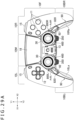
- FIG. 1 is a plan view illustrating the upper surface of an input device 1A according to an example of the embodiment of the present disclosure.
- FIG. 2 is a bottom view illustrating the lower surface of the input device 1A.
- FIG. 3 is a perspective view illustrating a side surface and the lower surface of the input device 1A.
- FIG. 4 is a perspective view illustrating the upper surface of the input device 1A, and illustrates a state in which an upper cover 20 and two stick units 30 to be described later are removed.
- FIG. 5 is an exploded perspective view of the input device 1A.
- an X1 direction and an X2 direction of an X-axis (direction in which left and right grips 10BL and 10BR to be described later are arranged side by side) illustrated in FIG. 1 and the like are respectively set as a right direction and a left direction.
- a Y1 direction and a Y2 direction of a Y-axis perpendicular to the X-axis are respectively set as a frontward direction and a rearward direction.
- a Z1 direction and a Z2 direction of a Z-axis (extending direction of operation sticks 400 to be described later) perpendicular to the X-axis and the Y-axis illustrated in FIG.
- the input device 1A is used as a game-purpose input device for an information processing device that has a function of executing a game program.
- the input device 1A may be used as an input device for an information processing device that has a function of reproducing moving images, a function of communicating via the Internet, and the like.
- the input device 1A is capable of communication with the information processing device wiredly or wirelessly.
- the input device 1A transmits, to the information processing device, a signal corresponding to an operation performed on the input device 1A by a user.
- the input device 1A has a main body 10 (see FIG. 4 ) that forms the external surface of the input device 1A.
- the main body 10 includes an upper case 40 and a lower case 80 (see FIG. 5 ) as well as an internal structure such as a main frame 50 (see FIG. 5 ) housed in these cases.
- An upper cover 20 (first exterior cover) and a lower cover 90 (second exterior cover) are attached to the main body 10.
- the upper case 40 and the lower case 80 may be referred to simply as cases 40 and 80.
- the upper cover 20 and the lower cover 90 may be referred to simply as covers 20 and 90.
- a part of the external surface of the input device 1A is formed by the cases 40 and 80, and another part thereof is formed by the covers 20 and 90.
- the external surface of the input device 1A includes an upper surface 1d (see FIG. 1 ) facing upward (first direction), a front surface 1e (see FIG. 3 ) facing frontward (second direction orthogonal to the first direction), and a lower surface 1f (see FIG. 3 ) facing downward.
- the upper surface 1f is a surface formed by the upper case 40 and the upper cover 20.
- the main body 10 of the input device 1A has four operation buttons 11 and a direction key 12 protruding upward from the upper surface 1d, an operation pad 18, and the like.
- the input device 1A has operation sticks 400 that protrude upward from the upper surface 1d.
- the lower surface 1f is a surface formed by the lower case 80 and the lower cover 90. Rear switches 19 and rear buttons 17 to be described later are arranged on the lower surface 1f.
- the front surface 1e is a surface that couples the front side of the upper surface 1d and the front side of the lower surface 1f to each other.
- the main body 10 of the input device 1A has two operation buttons 15 and two trigger buttons 16 that protrude frontward from the front surface 1e.
- the main body 10 of the input device 1A includes a device front portion 10F on which a plurality of operation members are arranged.
- the device front portion 10F includes: a right portion 10R on which the four operation buttons 11 as push buttons are arranged; a left portion 10L on which the direction key 12 is disposed; and a central portion 10M as a part between the right portion 10R and the left portion 10L.
- the two operation buttons 15 are respectively arranged on the front surface of the right portion 10R and the front surface of the left portion 10L.
- the two trigger buttons 16 are respectively arranged below the two operation buttons 15.
- the input device 1A has a right grip 10BR extending rearward from the right portion 10R of the device front portion 10F and a left grip 10BL extending rearward from the left portion 10L of the device front portion 10F.
- the right grip 10BR and the left grip 10BL extend rearward of a rear edge 10Ma of the central portion 10M.
- a rear end of the right grip 10BR and a rear end of the left grip 10BL are located rearward of the rear edge 10Ma of the central portion 10M.
- the user can stably grip the input device 1A by supporting the right grip 10BR by a right hand and supporting the left grip 10BL by a left hand. In this state, the user can perform operations of pressing the operation buttons 11 downward by a thumb of the right hand, pressing the direction key 12 by a thumb of the left hand, or pressing the operation buttons 15 and the trigger buttons 16 rearward by an index finger or a middle finger.
- the main body 10 of the input device 1A has the operation pad 18 in a plate shape in the central portion 10M.
- the operation pad 18 has a touch sensor.
- the touch sensor is a capacitive-type sensor, for example.
- the touch sensor outputs a signal corresponding to the position of a finger touching the upper surface of the operation pad 18.
- the operation pad 18 may be supported so as to be vertically movable according to a depressing operation of the user.
- the input device 1A has the operation sticks 400 in the rear of the operation pad 18.
- the input device 1A has two operation sticks 400.
- the two operation sticks 400 are arranged on a rear portion of the central portion 10M, the rear portion being in the rear of the operation pad 18, and are arranged side by side in a left-right direction.
- One of the two operation sticks 400 is located on a left portion of the central portion 10M.
- the other is located on a right portion of the central portion 10M.
- the user can tilt the operation sticks 400 with respect to the center lines of the operation sticks 400 located at initial positions, and can also rotate the operation sticks 400 about the center lines.
- the operation sticks 400 may be vertically movably supported so as to function as operation buttons.
- An operation member (such as an operation button) different from the operation sticks 400 may be disposed between the two operation sticks 400.
- buttons 350 are respectively arranged in the rear of the two operation sticks 400.
- the function buttons 350 can, for example, be used as buttons for setting the environment of a game while the information processing device is executing the game (processing of the game program).
- instructions to an operation system can be input by operating the function buttons 350.
- the user can set the environment of the game by, for example, operating another operation member (for example, an operation button 11 or the direction key 12) while pressing one of the two function buttons 350.
- the "environment of the game” includes, for example, the volume of sound of the game generated from a speaker and the volume of sound in a voice chat (loudness of the voice of a partner), the magnitude or presence or absence of a vibration generated by a vibration motor 120 (see FIG. 5 ), the magnitude or presence or absence of a resistance to a depression of a trigger button 16, the sensitivity of the touch sensor possessed by the operation pad 18, the sensitivity of the operation sticks 400 (an amount of movement of a game screen, a game object, or the like relative to an angle of an operation stick 400), and the like.
- the "environment of the game” also includes an allocation of functions in the game to operation members such as the operation buttons 11 and the operation buttons 15.
- the function buttons 350 can also function as, for example, a shift key button or a control key button that imparts another function to another operation member (such as an operation button 11) other than the function buttons 350.
- the function buttons 350 project rearward from the central portion 10M of the input device 1A, and are arranged in a region A surrounded by the rear edge 10Ma of the central portion 10M, a right side surface 10La of the left grip, and a left side surface 10Ra of the right grip as viewed in plan as illustrated in FIG. 1 .
- Such an arrangement of the function buttons 350 does not hinder game play (operation of the operation buttons 11, the direction key 12, the operation sticks 400, and the like) by the user, and enables the user to operate the function buttons 350 promptly as necessary.
- the function buttons 350 are arranged in the rear of the operation sticks 400 that are operated by the thumbs of the user. More specifically, the function button 350 on a left side is disposed in the rear of the operation stick 400 located on a left portion of the central portion 10M, and the function button 350 on a right side is disposed in the rear of the operation stick 400 located on a right portion of the central portion 10M. Therefore, the user can easily operate the function button 350 on the right side by, for example, shifting the position of the thumb operating an operation member on the right portion 10R (for example, the operation stick 400 on the right side) rearward. In addition, the function button 350 on the left side can be operated easily by shifting the position of the thumb operating an operation member on the left portion 10L (for example, the operation stick 400 on the left side) rearward.
- the function buttons 350 can be pushed downward.
- the other operation members arranged on the upper surface 1d of the input device 1A are also members that can be pressed downward. That is, the operation direction of the function buttons 350 and the operation direction of the other operation members are the same.
- the user can press the function buttons 350 by the thumbs easily.
- an uneven pattern may be formed on the upper surfaces of the function buttons 350. This suppresses slippage of the thumbs of the user on the upper surfaces of the function buttons 350, and facilitates the operation of the function buttons 350 by using the thumbs.
- two holes H10 are provided in the lower surface 1f of the main body 10 of the input device 1A, and two rear buttons 17 (operated members) are respectively attached thereto.
- the two holes H10 are arranged side by side in the left-right direction in the device front portion 10F.
- One of the two holes H10 is located in a left portion of the main body 10.
- the other is located in a right portion of the main body 10.
- the two holes H10 are located frontward of the left grip 10BL and the right grip 10BR, and are located between the left grip 10BL and the right grip 10BR in the left-right direction.
- the lower surface 1f of the main body 10 of the input device 1A is provided with two holes H20 from which the rear switches 19 to be described later are exposed.
- the two holes H20 are located frontward of the two holes H10 in the device front portion 10F, and are arranged side by side in the left-right direction.
- the two holes H20 are located between the two trigger buttons 16 in the left-right direction.
- the rear buttons 17 attached to the respective holes H10 project downward from the lower surface 1f of the main body 10, and have an operated surface 17a to be pressed by a finger of the user.
- the operated surface 17a of the rear button 17 attached to the hole H10 on the left side (hole H10 on the right side in FIG. 2 ) of the two holes H10 faces a frontward and rightward oblique direction.
- the operated surface 17a of the rear button 17 attached to the hole H10 on the right side (hole H10 on the left side in FIG. 2 ) faces a frontward and leftward oblique direction.
- the rear button 17 on the left side can be pushed and tilted in a leftward and rearward oblique direction.
- the rear button 17 on the right side can be pushed and tilted in a rightward and rearward oblique direction.
- the user can perform an operation of pushing and tilting the rear buttons 17 by using middle fingers, for example, in a state in which the user is holding the left grip 10BL and the right grip 10BR. Because the user can perform an operation of pushing and tilting the rear button 17 on the left side toward the left grip 10BL, the user can easily operate the rear button 17 by using the middle finger of the left hand. Because the user can perform an operation of pushing and tilting the rear button 17 on the right side toward the right grip 10BR, the user can easily operate the rear button 17 by using the middle finger of the right hand.
- the rear buttons 17 are attached to the holes H10 by magnetic force.
- the user can remove the rear buttons 17 attached to the main body 10 without the use of a tool or the like.
- some games executed on the information processing device do not use the rear buttons 17. Therefore, because the rear buttons 17 are made removable, the user can optionally select whether or not to attach the rear buttons 17 to the input device 1A according to the kind of a game to be executed on the information processing device.
- the upper cover 20 is attached to the main body 10 of the input device 1A (more specifically, the upper case 40 to be described later, which is illustrated in FIG. 5 ), and covers the upper surface of the main body 10.
- the user can remove the upper cover 20 from the main body 10 without the use of a tool such as a driver. Structures for attachment of the rear buttons 17 will be explained later in detail.
- the main body 10 of the input device 1A has housing recessed portions U10 for housing stick units 30.
- the stick units 30 are operation member units including the operation sticks 400 and circuits for detecting movement of the operation sticks 400 (circuits mounted on circuit boards 320 illustrated in FIG. 16 ).
- the stick units 30 can be attached to and detached from the housing recessed portions U10 of the main body 10.
- the housing recessed portions U10 open upward (in the Z1 direction) and rearward (in the Y2 direction). That is, the housing recessed portions U10 open in a direction, which is indicated by an arrow D1 in FIG. 4 and is orthogonal to a circuit board 60 to be described later (see FIG. 5 ) (in the projecting direction of the operation sticks 400), and in a direction, which is indicated by an arrow D2 in the same figure and is along the circuit board 60.
- the user can extract the stick units 30 attached to the main body 10 rearward in a state in which the upper cover 20 is removed from the main body 10 and stopper members 77 to be described later are pulled outward in the left-right direction.
- the user can replace the stick units 30 with other stick units (for example, unused stick units, stick units including operation sticks 400 with a different height, or stick units provided with a decoration or the like).
- the housing recessed portions U10 open in the two directions of the upward direction (Z1 direction) and the rearward direction (Y2 direction), the user can extract the stick units 30 rearward, for example, while holding the upper sides of the stick units 30. The work of removing the stick units 30 can therefore be facilitated.
- the stick units 30 are provided with the operation sticks 400 and the function buttons 350.
- holes (openings) H30 and H40 that each expose at least a part of the stick units 30 are formed in the upper cover 20.
- the operation sticks 400 that project upward from the stick units 30 penetrate the holes H30 of the upper cover 20.
- the function buttons 350 that project rearward from the stick units 30 penetrate the holes H40 of the upper cover 20. Structures for attachment of the stick units 30 will be explained later in detail.
- the input device 1A has the upper cover 20, the two stick units 30, the upper case 40, the main frame 50 (first frame), the circuit board 60, a reinforcing frame 70 (second frame), the lower case 80, and the lower cover 90.
- the rear buttons 17 are removed.
- the upper case 40 and the lower case 80 are a housing that houses the internal structure of the input device 1A, and form the external surface of the input device 1A.
- the upper case 40 forms a part of the external surface of each of the device front portion 10F, the right grip 10BR, and the left grip 10BL.
- the lower case 80 forms a part of the external surface of each of the device front portion 10F, the right grip 10BR, and the left grip 10BL.
- the input device 1A includes, as the internal structure thereof, the main frame 50, the circuit board 60, and the reinforcing frame 70.
- the main frame 50 and the reinforcing frame 70 are attached to each other in an upward-downward direction.
- the circuit board 60 has a processor not illustrated, and is disposed in the central portion 10M of the input device 1A (see FIG. 1 ).
- the circuit board 60 is disposed between the main frame 50 and the reinforcing frame 70.
- a battery 110 is disposed between the reinforcing frame 70 and the lower case 80.
- the main frame 50 and the reinforcing frame 70 may be referred to simply as the frames 50 and 70.
- the upper case 40 covers the upper side of the internal structure (specifically, the main frame 50 and the reinforcing frame 70) of the input device 1A including the main frame 50 and the reinforcing frame 70, and is attached to the internal structure.
- the lower case 80 covers the lower side of the internal structure, and is attached to the internal structure, as with the upper case 40. Because the internal structure thus includes the reinforcing frame 70 in addition to the main frame 50, an improvement in the rigidity of the internal structure is achieved.
- the rigidity of the upper case 40 and the rigidity of the lower case 80 can be ensured by attaching the upper case 40 and the lower case 80 to the internal structure having a high rigidity.
- the upper case 40, the main frame 50, the reinforcing frame 70, and the lower case 80 are formed by a resin, for example. This facilitates the processing of the upper case 40, the main frame 50, the reinforcing frame 70, and the lower case 80, and increases a degree of freedom of the attachment positions of screws for fixing these (positions of attachment holes).
- the material of the upper case 40, the main frame 50, the reinforcing frame 70, and the lower case 80 is not limited to a resin, but may, for example, be a metal or the like.
- the upper case 40 has recessed portions U11 at positions at which the two stick units 30 are respectively arranged.
- the recessed portions U11 are formed at the rear edge of the upper case 40, and open toward the rear.
- the main frame 50 has recessed portions U12 at positions at which the two stick units 30 are respectively arranged.
- the recessed portions U12 are formed at the rear edge of the main frame 50, and open toward the rear.
- the housing recessed portions U10 (see FIG. 4 ) that house the stick units 30 are constituted by the recessed portions U11 of the upper case 40 and the recessed portions U12 of the main frame 50.
- the lower case 80 does not have recessed portions such as those of the upper case 40 and the main frame 50.
- recessed portions that house the stick units 30 and open only upward may be formed in the upper case 40 and the main frame 50 in place of the recessed portions U11 and U12.
- a circuit board mounted with switches corresponding to the respective operation buttons 11 may be disposed on the upper surface of the main frame 50.
- the switches may be membrane switches, for example.
- a resin sheet mounted with the membrane switches may be used as the circuit board.
- Switches corresponding to respective directions indicated by the direction key 12 may also be arranged under the direction key 12.
- FIG. 6 is a perspective view illustrating the lower side of the main frame 50.
- two vibration motors 120 are respectively attached to parts arranged inside the right grip 10BR and the left grip 10BL.
- Two trigger units 130L and 130R including the operation buttons 15 and the trigger buttons 16 are attached to the lower side of the main frame 50.
- the two trigger units 130L and 130R are attached to the lower side of the main frame 50 by screws.
- the two trigger units 130L and 130R are arranged side by side in the left-right direction.
- the trigger unit 130L is disposed in a left portion of the input device 1A (left portion 10L of the device front portion 10F).
- the trigger unit 130R is disposed in a right portion of the input device 1A (right portion 10R of the device front portion 10F).
- the two trigger units 130L and 130R may be referred to simply as trigger units 130.
- the main frame 50 has two attachment holes H51 (a first part and a second part) separated from each other in the left-right direction.
- the two recessed portions U12 formed in the main frame 50 are formed at positions separated from each other in the left-right direction.
- the two recessed portions U12 are formed between the two attachment holes H51 and H51.
- the reinforcing frame 70 is fixed to the attachment holes H51 and H51.
- the rigidity of the main frame 50 can be enhanced on the peripheries of the recessed portions U12.
- the two attachment holes H51 and H51 are respectively arranged in the vicinities of the vibration motors 120. Therefore, because the reinforcing frame 70 is fixed to the attachment holes H51 and H51, the rigidity of the main frame 50 can be enhanced on the peripheries of the vibration motors 120.
- the circuit board 60 is attached to the lower side of the main frame 50.
- the circuit board 60 has substantially the shape of a letter T, which is a shape avoiding the two recessed portions U12 formed in the main frame 50.
- the circuit board 60 includes a rectangular board front portion 61 located below the operation pad 18 and a board rear portion 62 extending rearward from a lower end of the center of the board front portion 61.
- the recessed portions U12 are secured in the rear of a right portion and a left portion of the board front portion 61.
- the board rear portion 62 is disposed between the two recessed portions U12.
- the surface area of the circuit board 60 can be increased, and a space for arranging wiring and mounting components on the circuit board 60 can be secured, as compared with a case where the circuit board 60 includes only the rectangular board front portion 61.
- the reinforcing frame 70 is attached to the main frame 50, and is disposed below the main frame 50.
- the reinforcing frame 70 is, for example, formed by a material having a higher rigidity than the main frame 50.
- the rigidity of the whole of the internal structure including the main frame 50, the circuit board 60, and the like can be secured by attaching the reinforcing frame 70 to the main frame 50.
- the upper case 40 and the lower case 80 are fixed to the internal structure including the main frame 50 and the reinforcing frame 70 by screws not illustrated in the figure. This can secure the rigidity of the upper case 40 and the lower case 80, and thus improves the rigidity of the input device 1A as a whole.
- the reinforcing frame 70 includes a frame front portion 71 for supporting the board front portion 61 of the circuit board 60 and a frame rear portion 72 for supporting the board rear portion 62 of the circuit board 60.
- the frame front portion 71 and the frame rear portion 72 are of a rectangular shape, for example.
- the frame rear portion 72 is connected to the rear edge of the frame front portion 71, and is of a rectangular shape longer in the left-right direction than the frame front portion 71.
- Two stages 73 (see FIG. 4 ) on which the two stick units 30 are respectively arranged are secured in a right portion and a left portion of the frame rear portion 72.
- the board rear portion 62 is disposed between the two stages 73 in the frame rear portion 72.
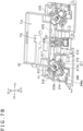
- FIG. 7A is a perspective view illustrating the lower side of the reinforcing frame 70 to which the rear buttons 17 are attached.
- FIG. 7B is a perspective view illustrating the lower side of the reinforcing frame 70, and is a diagram illustrating a state in which the rear buttons 17 and falling-off preventing members 220 to be described later are removed.
- a box-shaped housing portion 71a for housing the battery 110 is formed in the frame front portion 71 of the reinforcing frame 70.
- a recessed portion 71b for housing a cable connected to the battery 110 is formed on the inside of the housing portion 71a.
- a plurality of attachment holes H71, H72, H75, and H76 are formed in the reinforcing frame 70.
- a plurality of the attachment holes H71 and a plurality of the attachment holes H72 are arranged side by side in the left-right direction at the rear edge of the reinforcing frame 70.
- a plurality of the attachment holes H76 are respectively located at the left edge and the right edge of the reinforcing frame 70, and are formed frontward of the attachment holes H71.
- the attachment hole H75 (see FIG. 8 ) is located on the inside of the housing portion 71a.
- the attachment hole H75 may be located between the attachment holes H76.
- FIG. 8 is an exploded perspective view illustrating structures for attachment of the upper case 40, the main frame 50, the circuit board 60, the reinforcing frame 70, and the lower case 80.
- FIG. 9 is an exploded perspective view illustrating the lower case 80 and the lower cover 90.
- the lower case 80 has a plurality of attachment holes H81, H82, H86, H88, and H89 formed therein as attachment portions to be attached to at least one of the upper case 40, the main frame 50, and the reinforcing frame 70.
- a plurality of the attachment holes H81 and H82 are arranged side by side in the left-right direction along the rear edge of the case 80.
- a plurality of the attachment holes H86 are located between the front edge and the rear edge of the case 80, and are formed so as to be separated from each other in the left-right direction.
- the two attachment holes H88 are formed in rear end portions of the left and right grips 10BR and 10BL.
- the two attachment holes H89 are provided at the front edge of the case 80. Specifically, the two attachment holes H89 are formed at the edges of openings within which the operation buttons 15 are arranged.
- the input device 1A has a plurality of screws. These screws fix the lower case 80 to at least one of the upper case 40, the main frame 50, and the reinforcing frame 70. Attachment holes (attachment portions) into which common screws are inserted are formed in each of the upper case 40, the main frame 50, the reinforcing frame 70, and the lower case 80.
- respective screws inserted into the attachment holes H82 (see FIG. 9 ) of the lower case 80 are respectively passed through the attachment holes H72 (see FIG. 7A ) of the reinforcing frame 70 along straight lines L2 and L3 (see FIG. 8 ), respectively, and are fitted into attachment holes (not illustrated) of the upper case 40.
- the attachment holes H72 of the reinforcing frame 70 are not fixed to the main frame 50. However, between the attachment holes H72, a part of the reinforcing frame 70, which is between the two recessed portions U12 of the main frame 50, is fitted to the inside of the upper case 40. Thus, rattling of the main frame 50 can be suppressed between the attachment holes H72 and H72.
- Screws inserted into the attachment holes H86 (see FIG. 9 ) of the lower case 80 from the lower side are fitted into the attachment holes H76 of the reinforcing frame 70.
- screws inserted into attachment holes H88 and H88 located in rear end portions of the left and right grips 10BL and 10BR in the lower case 80 are passed through attachment holes H58 and H58 of the main frame 50 along straight lines L5 and L6, and are fitted into attachment holes (not illustrated) of the upper case 40.
- rattling of rear end portions of the main frame 50 parts in the rear of the vibration motors 120
- screws inserted into the attachment holes H89 (see FIG. 9 ) formed at the front edge of the lower case 80 from the lower side are fitted into attachment holes of the upper case 40.
- a screw inserted into the attachment hole H75 of the reinforcing frame 70 is passed through an attachment hole (not illustrated) of the circuit board 60 and an attachment hole H55 (see FIG. 6 ) of the main frame 50 along a straight line L7, and is fitted into an attachment hole (not illustrated) of the upper case 40.
- the circuit board 60 is fixed between the main frame 50 and the reinforcing frame 70.
- the board rear portion 62 (see FIG. 5 ) of the circuit board 60 is fitted, between the attachment holes H72 (see FIG. 7A ) of the reinforcing frame 70, to the inside of the upper case 40. Consequently, rattling of the board rear portion 62 can also be suppressed.
- the plurality of screws that are inserted into the lower case 80 are inserted from the lower side of the lower case 80 toward the upper case 40. As illustrated in FIG. 4 , the screws are not exposed from the upper case 40 in a state in which the upper cover 20 is removed from the input device 1A to replace the stick units 30. Therefore, even in the state in which the upper cover 20 is removed from the input device 1A, the external appearance of the input device 1A can be made excellent, and accidental removal of the screws by the user can be prevented.
- the lower cover 90 forms the left side surface 10Ra of the right grip 10BR and the right side surface 10La of the left grip 10BL.
- the lower cover 90 exposes the lower case 80 at a right side surface 10Rb of the right grip 10BR and a left side surface 10Lb of the left grip 10BL.
- the surface (left side surface 10Ra) of a right portion 90R (see FIG. 9 ) of the lower cover 90 has the form of a surface (part indicated by hatching in FIG. 9 ) different from the right side surface 10Rb of the right grip 10BR.
- the surface (right side surface 10La) of a left portion 90L (see FIG. 9 ) of the lower cover 90 has the form of a surface different from the left side surface 10Lb of the left grip 10BL.
- a description that "form of a surface is different” means that a tactile feeling (texture) when the user touches the surface is different, and means that, for example, the shape or material (hardness or the like) of the surface is different.
- the form of the surfaces is different from the right side surface 10Rb of the right grip 10BR and the left side surface 10Lb of the left grip 10BL.
- the fingers of the user are in contact with the surfaces facing the center of the input device 1A in the external surfaces of the left and right grips 10BL and 10BR.
- the regions in which the form of the surfaces is different are provided to the parts touched by the fingers of the user on the lower cover 90, the user can select a lower cover 90 that makes the own fingers feel a desired tactile feeling.
- the surface of the lower cover 90 has an uneven pattern on the left side surface 10Ra of the right grip 10BR and the right side surface 10La of the left grip 10BL as the form of the surfaces different from the right side surface 10Rb of the right grip 10BR and the left side surface 10Lb of the left grip 10BL. Because an uneven pattern is thus formed on the parts with which the fingers are in contact, the user can grip the input device 1A more stably.
- the lower cover 90 may be formed by two-color molding. That is, the material of the parts on which the uneven pattern is formed may be different from the material of other parts.
- the parts on which the uneven pattern is formed may be formed by a resin having an elastic property or a rubber.
- no uneven pattern is formed on the right side surface 10Rb of the right grip 10BR and the left side surface 10Lb of the left grip 10BL. That is, no uneven pattern is formed on the right side surface 10Rb and the left side surface 10Lb constituting the outside of the input device 1A in the left-right direction. This suppresses wear of the uneven pattern due to contact of the outside of the input device 1A in the left-right direction with another member (a wall or a floor within a room or the like), and makes it possible to maintain the quality of the input device 1A over a long period of time.
- a part 90M constituting the central portion 10M in the lower cover 90 has no uneven pattern formed thereon either.
- the rear buttons 17 are arranged on the lower surface of the central portion 10M. Because no uneven pattern is formed on this part, the user can smoothly move fingers along the lower surface of the lower cover 90 in order to operate the rear buttons 17.
- the left portion 90L and the right portion 90R of the lower cover 90 are coupled to each other by the part 90M. Therefore, as compared with a structure in which the left portion 90L and the right portion 90R are two members independent of each other, it is possible to reduce the number of parts, and facilitate the assembling of the input device 1A.
- the lower cover 90 covers a part rearward of the two holes H20 that expose the rear switches 19 in the device front portion 10F.
- the front edge of the lower cover 90 is located rearward of the two holes H20. This can suppress a decrease in a space within the lower case 80 (space in which the internal structure including the frames 50 and 70 and the like is disposed) by an amount corresponding to a thickness part of the lower cover 90 on the periphery of the two holes H20.
- two holes H11 arranged side by side in the left-right direction are formed in the lower case 80.
- Two holes H12 arranged side by side in the left-right direction are also formed in the lower cover 90.
- the holes H11 and the holes H12 are located at same positions in the left-right direction and the front-rear direction, and constitute the holes H10 into which the rear buttons 17 are inserted.
- a plurality of engaging portions 81 are formed in the lower case 80.
- the engaging portions 81 are, for example, holes or recessed portions.
- Engaging portions 91 (see FIG. 5 ) that catch the engaging portions 81 are formed on the cover 90.
- the engaging portions 91 are, for example, projecting portions to be fitted into the engaging portions 81 as holes or recessed portions, and pawls are formed on the projecting portions.
- the lower cover 90 can be attached to the lower case 80 by engagement between the engaging portions 81 and 91.
- the upper cover 20 has edge portions 24 at parts of the peripheral edge thereof, and the lower cover 90 has edge portions 92 at parts of the peripheral edge thereof, the edge portions 92 being adjacent to the edge portions 24 of the upper cover 20. Because the upper cover 20 and the lower cover 90 thus have the edge portions 24 and 92 adjacent to each other, the external appearance of the input device 1B can be made excellent.
- the upper cover 20 has a rear wall portion 23 constituting a rear edge in a central portion of the upper cover 20, and has the edge portions 24 respectively at a right portion and a left portion thereof located on opposite sides from each other with the rear edge of the upper cover 20 interposed therebetween.
- the lower cover 90 has the edge portions 92 respectively at the right portion and the left portion thereof.
- the edge portions 24 (protruding edges) located at the right portion and the left portion of the upper cover 20 are located rearward of the rear edge located in the central portion of the upper cover 20 (more specifically, the external surface of the rear wall portion 23).
- the lower cover 90 forms the left side surface 10Ra of the right grip 10BR and the right side surface 10La of the left grip 10BL.
- the two edge portions 92 of the lower cover 90 are respectively arranged at the left side surface 10Ra of the right grip 10BR and the right side surface 10La of the left grip 10BL.
- the two edge portions 24 of the upper cover 20 are respectively adjacent to the left side surface 10Ra of the right grip 10BR and the right side surface 10La of the left grip 10BL.
- the external surface of the upper cover 20 and the external surface of the lower cover 90 at the edge portions 24 are flush with each other at the edge portions 24 and 92. This can further improve the external appearance of the input device 1B.
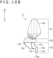
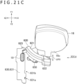
- FIG. 10A is a view of the operated surface 17a of a rear button 17 as viewed from the front.
- FIG. 10B is a side view of the rear button 17.
- the two rear buttons 17 attached to the input device 1A have the same shape. However, the two rear buttons 17 may be different from each other in shape.
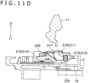
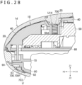
- FIG. 11A is a sectional view taken along a line XIA-XIA in FIG. 7A .
- FIG. 11B , FIG. 11C , and FIG. 11D are views illustrating an action of removing the rear button 17 in the sectional view of FIG. 11A .
- the two rear buttons 17 can be attached to the reinforcing frame 70. More specifically, two supporting members 210 that respectively support the two rear buttons 17 are attached to the reinforcing frame 70, and the rear buttons 17 can be attached to the supporting member 210.
- the supporting members 210 and the rear buttons 17 can move integrally with each other about shaft portions 212 (see FIG. 7B ) formed in the supporting members 210.
- Two falling-off preventing members 220 are respectively arranged under (in the Z2 direction in FIG. 7A with respect to) the two supporting members 210.
- the falling-off preventing members 220 prevent the falling off of the shaft portions 212 possessed by the supporting member 210.
- the falling-off preventing members 220 are each attached to the reinforcing frame 70.
- the falling-off preventing members 220 are fixed to the reinforcing frame 70 by screws, for example.
- the supporting members 210 and the falling-off preventing members 220 may be formed by a metal. The rigidity of the supporting members 210 and the falling-off preventing members 220 can be thereby ensured.
- the material of the supporting members 210 and the falling-off preventing members 220 is not limited to a metal.
- the supporting members 210 and the falling-off preventing members 220 may be formed by a resin or the like. In addition, the supporting members 210 and the falling-off preventing members 220 may be formed by respective different materials.
- the two supporting members 210 are thus biased by one leaf spring 230, the number of parts can be reduced as compared with a case where two elastic members that bias the two supporting members 210 are provided.
- the elastic member that biases the supporting members 210 to the initial positions does not necessarily have to be the leaf spring 230.
- Two coil springs may be respectively provided to the two supporting members 210, or two leaf springs may be respectively provided to the two supporting members 210.
- the supporting members 210 attached to the reinforcing frame 70 include a base portion 211 having a hole H17 formed therein and two shaft portions 212 projecting from the base portion 211 in directions opposite from each other.
- the shaft portions 212 have a cylindrical shape, and are fitted into grooves formed in the reinforcing frame 70.
- the supporting member 210 can move about an axis Ax1 of the two shaft portions 212.
- the axis Ax1 extends in an oblique direction with respect to both the left-right direction and the front-rear direction so as to approach the center in the left-right direction of the input device 1A toward the rear (in the Y2 direction).
- the left side rear button 17 attached to the supporting member 210 can be pushed and tilted toward the left grip 10BL gripped by the user.
- the right side rear button 17 attached to the supporting member 210 can be pushed and tilted toward the right grip 10BR.
- the shaft portions 212 of the supporting member 210 are not limited to the example illustrated in FIG. 7B , but may be recessed portions or holes formed in two side surfaces facing each other. In this case, projecting portions to be fitted to the insides of the shaft portions 212 as recessed portions or holes may be formed on the reinforcing frame 70. In addition, the shaft portions 212 may be one shaft as long as the shaft does not interfere with the hole H17.
- the supporting member 210 has a first extending portion 213 that extends from the base portion 211 in a direction orthogonal to the axis Ax1 of the shaft portions 212 and that is pushed upward (in the Z1 direction) by the leaf spring 230.
- the supporting member 210 has a second extending portion 214 that extends from the base portion 211 in an opposite direction (direction indicated by a straight line Ax2 in FIG. 7B ) from the direction in which the first extending portion 213 extends.
- the second extending portion 214 is provided on an opposite side from the first extending portion 213 with the shaft portions 212 interposed therebetween. As illustrated in FIG.
- the falling-off preventing member 220 regulates the falling off of the shaft portions 212 from the grooves formed in the reinforcing frame 70.
- the falling-off preventing member 220 is substantially U-shaped.
- the falling-off preventing member 220 covers the second extending portion 214 in addition to the two shaft portions 212.
- the input device 1A has a sensor (switch) 240 that outputs a signal corresponding to movement of the supporting member 210.
- a sensor board 240a mounted with the sensor 240 may be attached to the reinforcing frame 70, for example.
- the sensor 240 is separated from the axis Ax1 in the direction orthogonal to the axis Ax1 (direction indicated by the straight line Ax2 in FIG. 7B ).
- the sensor 240 is disposed between the reinforcing frame 70 and the second extending portion 214 of the supporting member 210.
- the upper case 40 and the lower case 80 as a housing that houses the internal structure of the input device 1A house the supporting member 210, the falling-off preventing member 220, the leaf spring 230, and the sensor 240 together with the reinforcing frame 70.
- the rear button 17 extends in a direction orthogonal to the axis Ax1 and intersecting the straight line Ax2. Specifically, as illustrated in FIG. 2 , FIG. 7A , and FIG. 7B , the rear button 17 extends downward (in the Z2 direction) from the position of the axis Ax1. Then, the rear button 17 projects from the lower case 80 and the lower cover 90.
- the rear button 17 is attached to the supporting member 210 so as to move together with the supporting member 210. More specifically, as illustrated in FIG. 7A and FIG. 7B , the rear button 17 is attached to the inside of the hole H17 formed in the base portion 211 of the supporting member 210.
- the rear button 17 includes an insertion portion 172 that is inserted into the hole H17.
- the insertion portion 172 has a surface (inclined surface 17g to be described later) that is in contact with the inside of the hole H17 in an operating direction of the rear button 17 (rotational direction about the axis Ax1). Thus, due to this contact, the rear button 17 moves together with the supporting member 210.
- the second extending portion 214 of the supporting member 210 is located on the lower side of the sensor 240.
- the second extending portion 214 of the supporting member 210 slightly moves upward, and presses the sensor 240.
- the sensor 240 When the sensor 240 is pressed by the second extending portion 214, the sensor 240 outputs a signal corresponding to the pressing. It is thereby possible to detect the pushing operation of the user on the rear button 17.
- the rear button 17 includes a projecting portion 171 that projects downward from the lower case 80 and the lower cover 90 in a state in which the rear button 17 is attached to the input device 1A.
- the rear button 17 includes the insertion portion 172 that is inserted into the hole H17 formed in the base portion 211 of the supporting member 210 and a supported portion 173 that covers the opening of the hole H17 in a state in which the insertion portion 172 is inserted in the hole H17.
- the projecting portion 171 has the operated surface 17a that is operated by a finger of the user.
- the projecting portion 171, the supported portion 173, and the insertion portion 172 formed in the rear button 17 are arranged in the upward-downward direction in this order.
- a width W173 of the supported portion 173 is larger than a width W172 of the insertion portion 172.
- the supported portion 173 may be in contact with a lower surface 211b (see FIG. 7B ) of the base portion 211 of the supporting member 210.
- a width W171 of the projecting portion 171 is larger than the width W173 of the supported portion 173.
- the width W171 of the projecting portion 171 is larger than twice the width W173 of the supported portion 173 (more specifically, three times the width W173). It is thereby possible to make the operated surface 17a of the projecting portion 171 wider and thus facilitate operation of the user on the operated surface 17a.
- the projecting portion 171 (operated surface 17a) of the rear button 17 is formed in substantially a semicircular shape.
- the operated surface 17a of the rear button 17 has a shape in which a lower end at a center thereof in the direction of the axis Ax1 bulges.
- the insertion portion 172 of the rear button 17 includes a curved portion 17b that extends upward (in the Z1 direction) (direction of separating from the supported portion 173) from the supported portion 173 and then extends toward the first extending portion 213 (see FIG. 11A ) of the supporting member 210.
- the curved portion 17b and the supported portion 173 form a recessed portion 17c.
- a projecting portion 172a (first projecting portion) that projects upward is formed as an end (end portion in the Z1 direction) of the insertion portion 172.
- the projecting portion 172a has a magnetic force receiving surface 17d facing in the direction of a magnet 250 to be described later and a stopper target surface 17e facing in an opposite direction from the magnetic force receiving surface 17d in a state in which the rear button 17 is attached to the supporting member 210.
- the stopper target surface 17e faces in a direction in which the sensor 240 is located.
- the insertion portion 172 includes a projecting portion 17f (first projecting portion) that projects from the curved portion 17b toward the sensor 240.
- a recessed portion (groove portion) 210a recessed with a narrow width toward the direction of the sensor 240 is formed in the inner surface of the hole H17 formed in the base portion 211 of the supporting member 210.
- the projecting portion 17f formed in the rear button 17 is fitted into this recessed portion 210a.
- a direction in which the rear button 17 is oriented with respect to the hole H17 can be thereby limited to only one direction. That is, movement (rattling) of the rear button 17 in the direction along the axis Ax1 can be suppressed.
- the supporting member 210 includes the magnet 250.
- the rear button 17 is formed by a magnetic substance such as iron.
- the rear button 17 is attached to the supporting member 210 by the magnetic force of the magnet 250. That is, the insertion portion 172 of the rear button 17 receives the magnetic force of the magnet 250, and is retained on the inside of the hole H17. At this time, the magnetic force receiving surface 17d is pulled by the magnet 250, and the inner surface of the recessed portion 210a of the supporting member 210 supports the projecting portion 17f of the rear button 17.
- the rear button 17 may, for example, have a magnet, and may be attached to the supporting member 210 by the magnetic force of the magnet.
- the supporting member 21 may be formed by a magnetic substance.
- a part of the rear button 17 may be formed by a magnetic substance (or a magnet).
- the insertion portion 172 of the rear button 17 or the projecting portion 172a at the end of the insertion portion 172 it suffices for the insertion portion 172 of the rear button 17 or the projecting portion 172a at the end of the insertion portion 172 to be a magnetic substance (or a magnet).
- the magnet 250 is retained by the first extending portion 213 of the supporting member 210, and is located between the first extending portion 213 and the reinforcing frame 70.
- the magnet 250 is disposed on an opposite side from the sensor 240 with the axis Ax1 interposed therebetween, the axis Ax1 being defined by the shaft portions 212 of the supporting member 210.
- the magnet 250 is disposed on an opposite side from the sensor 240 with respect to the base portion 211 of the supporting member 210 (position in which the rear button 17 is attached).
- the rear button 17 can move about the shaft portions 212 between the initial position indicated by a solid line in FIG. 11A and a first inclination posture indicated by a chain double-dashed line in FIG. 11A .
- the rear button 17 can move between the initial position and the first inclination posture together with the supporting member 210.
- the first inclination posture is defined in a first rotational direction R1 (see FIG. 11A ) about the axis Ax1 (see FIG. 7B ) defined by the shaft portions 212 of the supporting member 210 with respect to the initial position.
- the rear button 17 presses the sensor 240 via the second extending portion 214 of the supporting member 210.
- the supporting member 210 is biased to the initial position by the leaf spring 230 (see FIG. 7B ).
- the leaf spring 230 is disposed in an opposite direction from the sensor 240 with the axis Ax1 of the supporting member 210 interposed therebetween. This makes it possible to easily avoid interference between the leaf spring 230 and the sensor 240 and secure a sufficient size of the leaf spring 230.
- a projecting portion 210b is formed at the edge of the opening of the hole H17 formed in the supporting member 210.
- the projecting portion 210b is fitted into the recessed portion 17c formed in the insertion portion 172 of the rear button 17.
- the magnetic force receiving surface 17d of the insertion portion 172 is located above (in the Z1 direction with respect to) the projecting portion 210b.
- an inclined surface 17g is formed on the projecting portion 17f of the rear button 17.
- the inclined surface 210c is formed also on the recessed portion 210a of the hole H17 formed in the supporting member 210.
- the inclined surface 17g of the rear button 17 is in contact with the inclined surface 210c of the supporting member 210 also when the rear button 17 is at the initial position. It is thereby possible to suppress rattling of the rear button 17 against the supporting member 210 when the user operates the rear button 17.
- the rear button 17 can be moved to a second inclination posture illustrated in FIG. 11B .
- the second inclination posture is defined in a second rotational direction R2 as an opposite direction from the first rotational direction R1 with respect to the initial position in FIG. 11A .
- the projecting portion 210b (see FIG. 11A ) formed on the supporting member 210 is fitted in the recessed portion 17c formed in the rear button 17.
- the rear button 17 can be moved from the initial position to the second inclination posture about a distal end of the projecting portion 210b.
- movement of the supporting member 210 is regulated by the falling-off preventing member 220.
- the rear button 17 is allowed to move in the downward direction (the Z2 direction or the projecting direction of the projecting portion 171), as illustrated in FIG. 11C and FIG. 11D , in a state in which the rear button 17 is in the second inclination posture. That is, the rear button 17 is allowed to move in a direction orthogonal to the axis Ax1.
- the rear button 17 can be removed from the supporting member 210 by an operation of the user from the outside of the upper case 40 and the lower case 80 as a housing.
- the user removes the rear button 17, the user needs to perform a two-step operation of extracting the rear button 17 in the upward-downward direction after moving the rear button 17 in the second rotational direction R2. It is therefore possible to suppress the falling of the rear button 17 off the supporting member 210 without an intention of the user.
- a width W21 of a passage defined by the distal end of the projecting portion 210b and a lower end of the inclined surface 210c that supports the insertion portion 172 is larger than a width W17 of the projecting portion 172a of the rear button 17. Therefore, when the posture of the rear button 17 (posture of the projecting portion 172a) coincides with the opening direction of the passage defined by the distal end of the projecting portion 210b and the lower end of the inclined surface 210c, the rear button 17 can be removed from the supporting member 210 in the opening direction.
- a corner portion 210d in the projecting portion 210b of the supporting member 210 fitted in the recessed portion 17c of the rear button 17, a corner portion 210d (see FIG.
- Supporting structures supporting the operation sticks 400 are detachably attached to the reinforcing frame 70.
- the supporting structures of the operation sticks 400 are attached to the upper surface of the reinforcing frame 70.
- the rear buttons 17 are detachably attached to the lower surface of the reinforcing frame 70.
- the two stages 73 are provided to the upper surface of the reinforcing frame 70.
- the two stick units 30 including the supporting structures of the operation sticks 400 are detachably attached to the two stages 73, respectively.
- the two stages 73 are exposed from the housing recessed portions U10 in a state in which the upper cover 20 and the two stick units 30 are removed from the input device 1A.
- FIG. 12 is a perspective view illustrating the circuit board 60, the reinforcing frame 70, and the stick units 30.
- FIG. 13 is a perspective view illustrating the lower surface of a stick unit 30.
- FIG. 14 is a rear view illustrating the rear side of the reinforcing frame 70 in a state in which the stick unit 30 is attached thereto.
- FIG. 15 is an exploded perspective view of the stick unit 30.
- FIG. 16 is a sectional view taken along a line XVI-XVI of FIG. 14 .
- the circuit board 60 is attached to the reinforcing frame 70.
- the circuit board 60 is disposed along the front-rear direction and the left-right direction in the main body 10 of the input device 1A.
- the stick units 30 can be attached to and detached from the housing recessed portions U10 illustrated in FIG. 4 in the front-rear direction.
- the circuit board 60 has connectors 63 (see FIG. 16 ) that open rearward.
- the stick units 30 have connectors 31 (see FIG. 16 ) that open frontward.
- the connectors 63 of the circuit board 60 and the connectors 31 of the stick unit 30 are fitted to each other in the front-rear direction.
- the stick units 30 are thereby electrically connected to the main body 10 of the input device 1A.
- the stick units 30 can be extracted rearward from the circuit board 60.
- the main body 10 of the input device 1A and the stick units 30 have guides that extend in the front-rear direction and that regulate movement of the stick units 30 in the front-rear direction.
- a guide projecting portion 74 that projects upward from the upper surface of the reinforcing frame 70 is formed on the stage 73 of the reinforcing frame 70.
- the guide projecting portion 74 includes a rectangular front end portion 74a projecting on the stage 73 and an extending portion 74b extending rearward from the front end portion 74a.
- the extending portion 74b is formed with a narrower width than the front end portion 74a in the left-right direction.
- a guide recessed portion 32 that opens downward and frontward is formed in a lower surface 310a of the stick unit 30 (lower surface of a pedestal member 310 to be described later).
- the guide projecting portion 74 of the reinforcing frame 70 fits into the guide recessed portion 32 of the stick unit 30. That is, the guide projecting portion 74 and the guide recessed portion 32 constitute a guide that regulates movement of the stick unit 30 in the front-rear direction.
- the guide recessed portion 32 includes: a first part 32a that extends rearward from a front end of the lower surface 310a of the pedestal member 310; a second part 32b that further extends rearward from the first part 32a and gradually decreases in width in the left-right direction; and a third part 32c that further extends rearward from the second part 32b.
- the front end portion 74a having a larger width in the left-right direction than the extending portion 74b of the guide projecting portion 74 passes through the first part 32a of the guide recessed portion 32, and catches inner walls of the second part 32b that gradually decreases in width in the left-right direction. It is thereby possible to suppress rattling in the left-right direction of the stick unit 30 attached to the housing recessed portion U10.
- the guide recessed portion 32 includes a rear end portion 32d located in the rear of the third part 32c. Projections that project to the inside of the guide recessed portion 32 are formed at a boundary between side surfaces of the third part 32c and side surfaces of the rear end portion 32d. The left and right projections formed at the boundary between the third part 32c and the rear end portion 32d sandwich the extending portion 74b of the guide projecting portion 74. It is thereby possible to suppress rattling in the left-right direction of the stick unit 30 in the housing recessed portion U10.
- guide walls 75L and 75R that extend upward are respectively formed on the left and right of the stage 73 in the reinforcing frame 70.
- the stick unit 30 is disposed between the guide wall 75L on the left side and the guide wall 75R on the right side.
- the left side surface of the stick unit 30 may be in contact with the guide wall 75L on the left side.
- the right side surface of the stick unit 30 may be in contact with the guide wall 75R on the right side. It is thereby possible to suppress rattling in the left-right direction of the stick unit 30.
- the main body 10 of the input device 1A has a stopper member 77.
- the stopper member 77 is attached to the reinforcing frame 70 constituting the main body 10 via a spring 78 as an elastic member.
- the stopper member 77 can be moved between a locking position (first position) for regulating movement in the front-rear direction of the stick unit 30 and an unlocking position (second position) for allowing movement in the front-rear direction of the stick unit 30.
- the stopper member 77 can move in a rotational direction R3 (see FIG. 14 ) about an axis Ax2 defined by a shaft portion to which the spring 78 is attached. As illustrated in FIG.
- the stopper member 77 when the stopper member 77 is at an initial position as the locking position by being biased by the spring 78, the stopper member 77 interferes with the stick unit 30 in the front-rear direction, and regulates rearward movement of the stick unit 30.
- the user can extract the stick unit 30 rearward by moving the stopper member 77 to the unlocking position in the rotational direction R3 against the elastic force of the spring 78.
- the pedestal member 310 forming the lower surface 310a of the stick unit 30 includes a projecting portion (guided portion) 310b projecting in the left direction at a lower edge on the left side of the pedestal member 310, and includes a projecting portion (guided portion) 310b projecting in the right direction at a lower edge on the right side of the pedestal member 310.
- a groove portion (guide portion) 76L recessed in the left direction is formed between the guide wall 75L on the left side and the stage 73.
- a groove portion (guide portion) 76R recessed in the right direction is also formed between the guide wall 75R on the right side and the stage 73.
- the left and right projecting portions 310b of the pedestal member 310 respectively enter the insides of the recessed portions 76L and 76R.
- the projecting portions 310b of the pedestal member 310 are sandwiched in the upward-downward direction by the inner surfaces of the recessed portions 76L and 76R. It is thereby possible to suppress rattling of the stick unit 30 also in the upward-downward direction.
- the stick unit 30 includes the pedestal member 310 and the connector 31, the circuit board 320, the supporting mechanism 330, a sensor part 340, the function button 350, a supporting member 360, a cover member 380, and the operation stick 400.
- the supporting mechanism 330 is a supporting mechanism that supports the operation stick 400.
- the supporting mechanism 330 has a supporting projecting portion 331 that projects upward.
- the supporting mechanism 330 allows the supporting projecting portion 331 to be inclined with respect to a center line along the upward-downward direction, and supports the supporting projecting portion 331 rotatably about the center line.
- the sensor part 340 has a contact 341 that detects movement of the function button 350.
- a recessed portion 424 that opens downward is formed in the operation stick 400 (more specifically, in a column portion 422 of a base member 420 to be described later).
- the supporting projecting portion 331 of the supporting mechanism 330 is inserted into this recessed portion 424.
- the operation stick 400 is thereby supported by the supporting projecting portion 331.
- the upper surface of the supporting projecting portion 331 may be in contact with a lower surface 424a formed on the inside of the recessed portion 424.
- the circuit board 320 is disposed on the upper side of the pedestal member 310 as a supporting member, and is supported by the pedestal member 310.
- a circuit for detecting movements of the operation stick 400 and the function button 350 is formed on the circuit board 320.
- the above-described connector 31 for electric connection to the main body 10 of the input device 1A is mounted on the circuit board 320.
- the supporting mechanism 330 and the sensor part 340 are also mounted on the circuit board 320.
- the connector 31 is disposed at a front end of the circuit board 320.
- the supporting mechanism 330 is disposed in the rear of the connector 31.
- the sensor part 340 is disposed in the rear of the supporting mechanism 330.
- the connector 31, the supporting mechanism 330, and the sensor part 340 are arranged in the front-rear direction in this order. Arranging the connector 31, the supporting mechanism 330, and the sensor part 340 on the same circuit board 320 obviates a need for dedicated circuit boards for providing the connector and the sensor, and can reduce the number of parts of the stick unit 30.
- the circuit board 320 of the stick unit 30 is disposed in the rear of the circuit board 60 included in the main body 10 of the input device 1A. As with the circuit board 60, the circuit board 320 is disposed along the front-rear direction. The circuit board 320 is disposed at a same position as the circuit board 60 in the upward-downward direction. That is, the circuit board 320 and the circuit board 60 are located on a substantially same plane. As described above, the guide projecting portion 74 and the recessed portions 76L and 76R (see FIG. 14 ) of the reinforcing frame 70 extend in a direction along the circuit board 320. The stick unit 30 can be fitted into the main body 10 in the direction along the circuit board 320.
- the circuit board 60 included in the main body 10 and the circuit board 320 included in the stick unit 30 are arranged in the central portion 10M of the input device 1A.
- the sensor part 340 that detects movement of the function button 350 is mounted on the circuit board 320. This enables the function button 350 to be disposed in the rear of the operation stick 400 and project rearward from the central portion 10M, as illustrated in FIG. 1 .
- the cover member 380 is placed on the pedestal member 310, and covers at least a part of each of the pedestal member 310, the supporting mechanism 330, and the sensor part 340.
- the cover member 380 and the pedestal member 310 constitute a case that houses the connector 31, the circuit board 320, the supporting mechanism 330, and the sensor part 340.
- an outer circumferential portion of the cover portion 421 overlaps the edge of the hole H40 as viewed in plan. It is therefore possible to prevent the inside of the cover member 380 (inside of the stick unit 30) from being exposed to the outside in a state in which the stick unit 30 is removed from the main body 10.
- the size of the cover portion 421 is set such that the outer circumferential portion of the cover portion 421 and the edge of the hole H40 overlap each other even in a state in which the operation stick 400 is inclined until coming into contact with the edge of the hole H40.
- a protruding portion 383 that protrudes frontward from the upper wall portion 381 is formed frontward of the lower wall portion 382 of the cover member 380.
- the protruding portion 383 covers the upper surface and left and right side surfaces of the connector 31. Because the protruding portion 383 thus covers the connector 31, damage to the connector 31 due to an external impact can be prevented.
- a notch U20 that opens rearward is formed in the lower wall portion 382.
- the supporting member 360 is exposed rearward from the notch U20.
- the supporting member 360 has a shaft portion 361 in a cylindrical shape extending in the left-right direction, and is fixed to the inside of the stick unit 30.
- the supporting member 360 is, for example, disposed on the upper side of the sensor part 340.
- a recessed portion 351 is formed in the front surface of the function button 350.
- the shaft portion 361 of the supporting member 360 is supported on the inside of the recessed portion 351. Specifically, end portions of the shaft portion 361 are supported by the left and right side surfaces of the recessed portion 351.
- the function button 350 is rotatably supported by the shaft portion 361 of the supporting member 360.
- the contact 341 of the sensor part 340 is provided on the rear surface of the sensor part 340.
- a projecting portion 352 is formed on the front surface of the function button 350.
- the projecting portion 352 of the function button 350 is formed on the lower side of the recessed portion 351 that houses the shaft portion 361 of the supporting member 360.
- the projecting portion 352 pushes the contact 341 when the function button 350 is pushed by the user and thereby moves about the shaft portion 361.
- the sensor part 340 can detect the pushing operation of the user on the function button 350.
- the contact 341 can move in a direction along the circuit board 320 (specifically, in the front-rear direction).
- the function button 350 can move in a direction intersecting the circuit board 320 (specifically, in the upward-downward direction).
- the function button 350 can move in a rotational direction R4 (see FIG. 16 ) about an axis Ax3 defined by the shaft portion 361 of the supporting member 360. Because the shaft portion 361 of the supporting member 360 thus converts the direction in which the function button 350 moves from the upward-downward direction to the front-rear direction, the movable direction of the contact 341 with respect to the circuit board 320 can be changed to a direction along the circuit board 320.
- the pushing direction of the function button 350 is the same as the pushing direction of the operation buttons 11 and the like (downward direction), so that user operation on the function button 350 is facilitated.
- FIG. 17 is an exploded perspective view of an operation stick 400.
- FIG. 18A and FIG. 18B are sectional views of the operation stick 400.
- FIG. 18A and FIG. 18B illustrate sections obtained by two cutting planes that perpendicularly intersect each other.
- FIG. 18A is a sectional view obtained by a cutting plane parallel with the Y-axis and the Z-axis
- FIG. 18B is a sectional view obtained by a cutting plane parallel with the X-axis and the Z-axis.
- the rotational positions about the Z axis of the operation stick 400 are not limited to the examples illustrated in FIG. 18A and FIG. 18B .
- FIG. 18B may be a sectional view obtained by a cutting plane parallel with the Y-axis and the Z-axis
- FIG. 18A may be a sectional view obtained by a cutting plane parallel with the X-axis and the Z-axis.
- the operation stick 400 includes a top member 410 having an upper surface 410a to be touched by a finger of the user and a base member 420 to which the top member 410 is attached.
- the top member 410 includes a disk-shaped top portion 411 including the upper surface 410a and a tubular portion 412 extending downward from the top portion 411.
- the tubular portion 412 of the top member 410 has a plurality of extending portions 413 that extend in the upward-downward direction and that constitute a lower end of the tubular portion 412.
- the top member 410 and the base member 420 may be formed by a resin, for example.
- the top portion 411 and the tubular portion 412 may be formed integrally with each other, or may be formed as respective separate members.
- the material of the top portion 411 may be different from the material of the tubular portion 412.
- the top portion 411 may be formed by an elastic material such as a rubber or an elastomer.
- the top member 410 may be molded by two-color molding. In this case, the upper surface 410a of the top portion 411 may be formed by an elastic material such as a rubber or an elastomer.
- the base member 420 includes a dome-shaped cover portion 421 and a column portion 422 that extends in the upward-downward direction. As illustrated in FIG. 18A , a recessed portion 424 is formed in the lower surface of the column portion 422. When the supporting projecting portion 331 extending upward from the supporting mechanism 330 is inserted into this recessed portion 424, the operation stick 400 including the column portion 422 is supported by the supporting projecting portion 331 (see FIG. 16 ). The cover portion 421 spreads in a radial direction from a lower end of the column portion 422. The column portion 422 is disposed in the center of the cover portion 421. In a state in which the base member 420 is supported by the supporting projecting portion 331 of the supporting mechanism 330, the cover portion 421 covers the upper side of the supporting mechanism 330.
- the column portion 422 of the base member 420 can be fitted into the inside of the tubular portion 412 of the top member 410.
- a plurality of holes H42 that surround a base portion of the column portion 422 are formed in the upper surface of the cover portion 421.
- the plurality of extending portions 413 formed on the top member 410 can be respectively fitted into these plurality of holes H42.
- an elastic member 430 is attached to the peripheral surface of the column portion 422 of the base member 420.
- the elastic member 430 is located on the inside of the tubular portion 412 of the top member 410, and catches the inner surface of the tubular portion 412.
- the elastic member 430 thereby limits upward movement of the top member 410. That is, the elastic member 430 regulates the slipping of the top member 410 from the base member 420.
- the elastic member 430 has, for example, a C-shape or a circular arc shape formed by a metal.
- the elastic member 430 is attached to the peripheral surface of the column portion 422 having a cylindrical shape. Without being limited to this, the elastic member 430 may have the shape of a rectangular frame. In addition, the column portion 422 may have a prism shape.
- the elastic member 430 is elastically deformable such that two end portions 431a and 431b thereof approach each other.
- the elastic member 430 has a slope 432 oriented obliquely downward.
- the tubular portion 412 of the top member 410 has, on an inner surface thereof, an engaging projecting portion 412a that engages with the slope 432 of the elastic member 430.
- the engaging projecting portion 412a projects from the inner surface of the tubular portion 412.
- the engaging projecting portion 412a has an upper surface 412c oriented obliquely upward with respect to the inner surface of the tubular portion 412 and a lower surface 412b oriented obliquely downward with respect to the inner surface of the tubular portion 412.
- the slipping of the top member 410 from the base member 420 can be regulated by thus limiting upward movement of the top member 410 by the elastic member 430 attached to the column portion 422 of the base member 420.
- the elastic member 430 is bent by being pressed by the engaging projecting portion 412a formed on the inside of the tubular portion 412.
- the user can extract the top member 410 from the base member 420 and replace the top member 410 with another operated member (for example, an operated member having a different height from the lower end to the top portion 411).
- a groove portion 423 to which the elastic member 430 is attached is formed in the external surface of the column portion 422 of the base member 420.
- the elastic member 430 catches the inside of the groove portion 423.
- the elastic member 430 is thereby attached to the base member 420.
- a projecting portion 433 that projects upward is formed on the elastic member 430.
- a recessed portion 423a is formed in the groove portion 423.
- the projecting portion 433 enters the inside of the recessed portion 423a.
- the projecting portion 433 comes into contact with the inner surface of the recessed portion 423a, and can thereby regulate rotation of the elastic member 430 about the axis of the column portion 422 along the upward-downward direction.
- the groove portion 423 extends to the two end portions 431a and 431b of the elastic member 430.
- the groove portion 423 is not formed between the two end portions 431a and 431b.
- the rotation of the elastic member 430 around the column portion 422 can be regulated also by contact of the end portions 431a and 431b with the inner surface of the groove portion 423 (end surfaces in a circumferential direction about the axis of the column portion 422).
- a thickness D1 in the Y-axis direction of the column portion 422 at a position at which the groove portion 423 is formed is smaller than a diameter D2 of a circle defined by the inner circumferential surface of the elastic member 430 having a C-shape or a circular arc shape. Therefore, a clearance is formed between the elastic member 430 and the column portion 422 in a direction orthogonal to the Z-axis direction. This clearance allows the elastic member 430 to be elastically deformed by being pressed by the engaging projecting portion 412a.
- a thickness D3 of the column portion 422 at the position at which the groove portion 423 is formed is larger than the thickness D1 of the column portion 422 and the diameter D2 of the circle defined by the elastic member 430 in the Y-axis direction illustrated in FIG. 18A . Therefore, at a position at which the projecting portion 433 ( FIG. 17 ) of the elastic member 430 is formed, no clearance is formed between the elastic member 430 and the column portion 422. Thus, the projecting portion 433 of the elastic member 430 catches the recessed portion 423a of the groove portion 423 formed in the column portion 422. It is thereby possible to suppress the falling of the elastic member 430 off the column portion 422 and movement of the elastic member 430 such that the elastic member 430 rotates with respect to the column portion 422.
- the base member 420 has a contact surface 421b (first surface) at a position lower than the position to which the elastic member 430 is attached, the contact surface 421b being in contact with the top member 410 in a direction orthogonal to the axis of the operation stick 400 along the upward-downward direction.
- This contact can regulate a positional displacement between the top member 410 and the base member 420 in the direction orthogonal to the axis of the operation stick 400.
- the top member 410 has the plurality of extending portions 413 that project downward from the tubular portion 412 and surround the column portion 422.
- the base member 420 has the plurality of holes H42 that surround the base portion of the column portion 422.
- the plurality of extending portions 413 are inserted into the plurality of holes H42.
- the external surfaces of the extending portions 413 (surfaces oriented outward in the radial direction of the operation stick 400) are in contact with the inner surfaces of the holes H42 (surfaces oriented inward in the radial direction of the operation stick 400). That is, the inner surfaces of the holes H42 function as the contact surface 421b. It is thereby possible to regulate a positional displacement between the top member 410 and the base member 420 in the Y-axis direction and the X-axis direction.
- the extending portions 413 are in contact with the inner surfaces of the holes H42 also in the circumferential direction of the operation stick 400. It is thereby possible to regulate a positional displacement between the top member 410 and the base member 420 in the circumferential direction of the operation stick 400.
- the inner surfaces of the extending portions 413 may be in contact with inner surfaces 422b of the holes H42 (surfaces oriented outward in the radial direction of the operation stick 400). This contact can also regulate a positional displacement between the top member 410 and the base member 420 in the direction orthogonal to the axis of the operation stick 400.
- the column portion 422 of the base member 420 has a contact surface (second surface) 422c at a position higher than the position to which the elastic member 430 is attached, the contact surface 422c being in contact with the top member 410.
- the contact surface 422c regulates a positional displacement between the top member 410 and the base member 420 in a direction orthogonal to the column portion 422.
- the column portion 422 has a first fitting portion 425 as a recessed portion at an upper end thereof.
- the top member 410 has a second fitting portion 415 as a projecting portion on a lower surface thereof.
- the first fitting portion 425 and the second fitting portion 415 are fitted to each other in the upward-downward direction. Then, the peripheral surface of the second fitting portion 415 is in contact with the inner surface of the first fitting portion 425. That is, the inner surface of the first fitting portion 425 functions as the contact surface 422c described above. This can regulate a positional displacement between the top member 410 and the base member 420 in the Y-axis direction and the X-axis direction orthogonal to the upward-downward direction in which the column portion 422 extends.
- the first fitting portion 425 may be a projecting portion.
- the second fitting portion 415 may be a recessed portion into which the first fitting portion 425 as a projecting portion is fitted. This also can regulate a positional displacement between the top member 410 and the base member 420 in the Y-axis direction and the X-axis direction.
- FIG. 19A and FIG. 19B are perspective views of a trigger unit 130 attached to the main frame 50.
- FIG. 19A is a view of the left side of a trigger unit 13 as viewed obliquely from below.
- FIG. 19B is a view of the left side of the trigger unit 130 as viewed obliquely from above.
- FIG. 20 is an exploded perspective view of the trigger unit 130.
- FIGS. 21A to 21D are views illustrating a part of members constituting the trigger unit 130, and illustrate the positions of a trigger button 16, a stopper member 620, and an operation member 630.
- FIGS. 21A to 21C illustrate the lower sides of the trigger button 16, the stopper member 620, and the operation member 630.
- FIG. 21A to 21D illustrate the lower sides of the trigger button 16, the stopper member 620, and the operation member 630.
- FIG. 21D illustrates the left side surfaces of the trigger button 16, the stopper member 620, and the operation member 630 in the state of FIG. 21C (view of the trigger button 16 and the like as viewed in the direction of an arrow XXId in FIG. 21C ).
- FIG. 19A and FIG. 19B illustrate the trigger unit 130L attached to the left side of the main frame 50
- the trigger unit 130R attached to the right side of the main frame 50 has a configuration similar to that of the trigger unit 130L on the left side.
- the trigger unit 130 has the operation button 15, the trigger button 16, and the rear switch 19.
- the trigger unit 130 includes a core unit 500 to which the operation button 15 and the trigger button 16 are attached and a stopper unit 600 that is attached to the core unit 500 and limits a movable range of the trigger button 16.
- the core unit 500 has a circuit board 510 and a motor 520.
- the circuit board 510 is attached to a side surface of the core unit 500.
- the motor 520 is attached to a rear end of the core unit 500. A rotating shaft of the motor 520 is disposed inside the core unit 500.
- the trigger button 16 has a supported portion H16 (see FIG. 21D ) in a base portion thereof.
- the supported portion H16 is a hole.
- a rod-shaped shaft member 501 (see FIG. 20 ) is fitted inside this hole H16.
- the trigger button 16 can move in a rotational direction R5 (see FIG. 21D ) about an axis Ax5 along the left-right direction which axis is defined by a shaft member 501.
- the stopper unit 600 includes a guide frame 610 as well as a stopper member 620 and an operation member 630 attached to the guide frame 610. As illustrated in FIG. 19A and FIG. 19B , the guide frame 610 is fixed to the core unit 500 by screws 641 and 642.
- the stopper member 620 is housed inside the upper case 40 and the lower case 80 as exterior members of the input device 1A.
- the rear switch 19 as a part of the operation member 630 is exposed to the outside (lower side) of the lower case 80 via the hole H20 (see FIG. 3 ).
- the rear switch 19 is formed integrally with the operation member 630, and projects downward from the operation member 630.
- a lower surface 16d of the trigger button 16 is curved so as to surround a center line Ax16 of the trigger button 16 along the front-rear direction.
- an opening 80a for exposing the trigger button 16 frontward is formed in the lower case 80.
- the edge of the opening 80a is curved along the lower surface 16d of the trigger button 16.
- a part 82a located on the periphery of the edge of the opening 80a is also curved so as to conform to the lower surface 16d of the trigger button 16 (this part 82a will hereinafter be referred to as a curved portion).
- the stopper member 620 moves along the curved portion 82a on the inside of the curved portion 82a of the lower surface 82. That is, the stopper member 620 moves along a curve on the inside of the curved portion 82a.
- a guide projecting portion 611 is formed in the guide frame 610.
- the guide projecting portion 611 is curved along the curved portion 82a.
- the stopper member 620 includes a guided portion 621.
- a recessed portion (groove portion) into which the guide projecting portion 611 is fitted is formed in the guided portion 621.
- the guided portion 621 is curved along the curved portion 82a.
- the stopper member 620 can move along the guide projecting portion 611.
- FIG. 21A illustrates a state in which the stopper member 620 is at an initial position (first position).
- FIG. 21C illustrates a state in which the stopper member 620 is at a final position (second position).
- FIG. 21B illustrates a state in which the stopper member 620 is at an intermediate position (third position) located between the initial position and the final position.
- the stopper member 620 is movable between the initial position illustrated in FIG. 21A and the final position illustrated in FIG. 21C .
- the stopper unit 600 is disposed on the left side of the trigger button 16.
- the rear edge (lower edge) of the trigger button 16 includes a rear edge 16b that projects more rearward than a rear edge 16a of a left portion of the trigger button 16 (rear edge on the stopper unit 600 side).
- the stopper member 620 has a head portion 622 as a stopper portion at a distal end of the guided portion 621, the head portion 622 projecting in the direction of the trigger button 16.
- the head portion 622 of the stopper member 620 limits the movable range of the trigger button 16 by abutting against the rear edge 16a or 16b as a stopper target portion of the trigger button 16.
- the head portion 622 of the stopper member 620 is located outside a region that the rear edges 16a and 16b pass when the trigger button 16 moves about the axis Ax5.
- the head portion 622 of the stopper member 620 is located leftward of the region that the rear edges 16a and 16b pass. Therefore, the interference of the head portion 622 with the rear edges 16a and 16b does not occur when the trigger button 16 moves about the axis Ax5.
- the trigger button 16 can move in the range of a distance ⁇ R1 (first range) as a maximum movable range.
- the stopper member 620 allows movement of the trigger button 16 in the range of the distance ⁇ R1 in a state in which the stopper member 620 is located at the initial position.
- the head portion 622 of the stopper member 620 is located midway in a region that the rear edge 16b (part projecting rearward) passes when the trigger button 16 moves about the axis Ax5. Therefore, when the trigger button 16 moves about the axis Ax5, the rear edge 16b abuts against the head portion 622 of the stopper member 620, and the movable range of the trigger button 16 becomes the range of a distance ⁇ R3 as a minimum movable range.
- the stopper member 620 limits the movable range of the trigger button 16 to the distance ⁇ R3 range smaller than the range of the distance ⁇ R1 in a state in which the stopper member 620 is located at the final position.
- the head portion 622 of the stopper member 620 is located midway in a region that the rear edge 16a (edge located frontward of the rear edge 16b) passes when the trigger button 16 moves about the axis Ax5. Therefore, when the trigger button 16 moves about the axis Ax5, the rear edge 16a abuts against the head portion 622 of the stopper member 620, and the movable range of the trigger button 16 becomes the range of a distance ⁇ R2 as an intermediate movable range.
- the stopper member 620 limits the movable range of the trigger button 16 to the distance ⁇ R2 range as a range between the range of the distance ⁇ R1 and the range of the distance ⁇ R3 in a state in which the stopper member 620 is located at the intermediate position.
- the shape of the stopper member 620 is not limited to the example illustrated in the figures.
- the stopper member 620 may not have the head portion 622 that projects toward the trigger button 16.
- the guided portion 621 of the stopper member 620 may abut against the edge 16a or 16b of the trigger button 16.
- the operation member 630 engages with the stopper member 620, and moves together with the stopper member 620.
- a projecting portion 623 that projects in the left direction (X2 direction) from an end portion (specifically, a front end portion) of the guided portion 621 is formed on the stopper member 620.
- a hole H63 (see FIG. 19B ) that opens in the left-right direction is formed in the operation member 630.
- the projecting portion 623 of the stopper member 620 is fitted to the inside of the hole H63. A movement of the operation member 630 is thereby transmitted to the stopper member 620 via the projecting portion 623.
- a recessed portion such as a notch or a groove into which the projecting portion 623 of the stopper member 620 is fitted may be formed in the operation member 630 in place of the hole H63.
- a recessed portion may be formed in the stopper member 620, and a projecting portion that fits into the recessed portion of the stopper member 620 may be formed on the operation member 630.
- the operation member 630 moves the stopper member 620 between the initial position illustrated in FIG. 21A and the final position illustrated in FIG. 21C .
- the stopper member 620 is disposed at the initial position (see FIG. 21A ).
- the stopper member 620 is disposed at the final position (see FIG. 21C ).
- the stopper member 620 is disposed at the intermediate position (see FIG. 21B ).
- the movable range of the trigger button 16 changes in a range of the distances ⁇ R1 to ⁇ R3 described above (see FIGS. 21A to 21C ).
- the user can set the movable range of the trigger button 16 to the range of one of the distances ⁇ R1 to ⁇ R3 and thus adjust the movable range of the trigger button 16.
- the operation member 630 can move in a direction different from that of the stopper member 620. Specifically, the operation member 630 can move along a straight line. The operation member 630 can move in a direction orthogonal to the rotational direction R5 in which the trigger button 16 moves. On the other hand, as illustrated in FIGS. 21A to 21C , the stopper member 620 moves in the left-right direction as viewed from the bottom of the trigger button 16. As described above, in the present embodiment, the stopper member 620 can move along the curved portion 82a of the lower case 80 (in other words, along the lower surface 16d of the trigger button 16). Because the moving direction of the operation member 630 and the moving direction of the stopper member 620 are thus made different from each other, the moving direction of the operation member 630 (rear switch 19) can be set to be a direction that facilitates the operation of the user.
- the operation member 630 can linearly move in the front-rear direction (Y-axis direction in FIG. 19A ) as the depression direction of the trigger button 16 along the lower surface of the guide frame 610.
- the user can move the rear switch 19 provided to the operation member 630 along the depression direction of the trigger button 16. This can make it easier to intuitively grasp that the rear switch 19 can set the movable range of the trigger button 16.
- the user can move the rear switch 19 exposed from the hole H20 in the front-rear direction.
- the whole of the operation member 630 including the rear switch 19 moves in the front-rear direction with respect to the guide frame 610.
- An uneven pattern is formed on the lower surface of the rear switch 19. This facilitates the operation of the user on the rear switch 19.
- the direction in which the operation member 630 and the rear switch 19 can be moved is not limited to the front-rear direction, but that the operation member 630 and the rear switch 19 may be able to be moved in the left-right direction, for example.
- the opening of the hole H63 formed in the operation member 630 extends in the upward-downward direction.
- the hole H63 regulates relative movement between the operation member 630 and the stopper member 620 in the front-rear direction (Y-axis direction), but allows relative movement therebetween in the upward-downward direction.
- the operation member 630 can move in a direction different from that of the stopper member 620.
- the operation member 630 includes a first plate portion 631 (see FIG. 21A ) having the lower surface of the operation member 630 and a second plate portion 632 (see FIG. 19B ) in which the hole H63 is formed.
- the second plate portion 632 connects to the first plate portion 631, and extends upward (in the Z1 direction in FIG. 19B ) from the first plate portion 631.
- a guide hole H61 (see FIG. 19B ) that opens in the upward-downward direction (Z-axis direction) is formed in the guide frame 610 to which the operation member 630 is attached.
- the second plate portion 632 of the operation member 630 is passed through the inside of this guide hole H61.
- the first plate portion 631 having the lower surface of the operation member 630 has a first recessed portion 631a and a second recessed portion 631b in a side surface thereof on the trigger button 16 side.
- An engaging member 612 (see FIG. 20 ) that projects to the side surface of the first plate portion 631 is attached to the guide frame 610.
- a distal end of the engaging member 612 catches a rear end of the first plate portion 631, and thereby limits rearward movement of the operation member 630.
- the operation member 630 is at the intermediate position illustrated in FIG.
- the distal end of the engaging member 612 catches the first recessed portion 631a.
- the engaging member 612 thereby retains the operation member 630 at the intermediate position.
- the engaging member 612 catches the second recessed portion 631b located frontward of the first recessed portion 631a, and thereby limits rearward movement of the operation member 630.
- the engagement of the operation member 630 with the engaging member 612 retains the operation member 630 at a predetermined position among the initial position, the intermediate position, and the final position respectively illustrated in FIGS. 21A to 21C , and sets the movable range of the trigger button 16 at one of a plurality of stages (three stages in the present embodiment).
- a torsion spring 644 is attached to the guide frame 610.
- One end of the torsion spring 644 catches the guide frame 610.
- Another end of the torsion spring 644 catches the engaging member 612.
- the torsion spring 644 thereby biases the engaging member 612 to the side surface of the operation member 630 (surface in which the recessed portions 631a and 631b are formed).
- the operation member 630 can be moved to the three positions described above against the elastic force of the torsion spring 644.
- FIG. 22 is a diagram illustrating the stopper member 620 and the circuit board 510 (see FIG. 20 ) that is attached to the core unit 500.
- the stopper member 620 has a projecting portion 624 that projects from the guided portion 621.
- the projecting portion 624 projects in a direction perpendicular to the direction in which the projecting portion 623 projects.
- the projecting portion 624 projects obliquely upward (Z1 direction) and rearward (Y2 direction) from the stopper member 620.
- An elastic member 650 is attached to a distal end of the projecting portion 624.
- the elastic member 650 is a sheet metal, for example.
- the elastic member 650 is fixed to the distal end of the projecting portion 624 by a screw 643.
- the projecting portion 624 of the stopper member 620 projects obliquely upward (Z1 direction) through a hole formed in the guide frame 610.
- the elastic member 650 attached to the projecting portion 624 is in contact with a guide slope 610a formed on the guide frame 610, and thereby presses the stopper member 620 against the guide frame 610. This can suppress a collision of the stopper member 620 with the guide frame 610 and the occurrence of an impact sound when the trigger button 16 collides with the stopper member 620.
- the circuit board 510 attached to the core unit 500 is mounted with a first sensor 511, a second sensor 512, and a processor not illustrated.
- the first sensor 511 is one for detecting the position of the stopper member 620.
- the first sensor 511 has a movable projecting portion 511a that projects toward the stopper member 620.
- the stopper member 620 has two wall portions 625a and 625b that project toward the first sensor 511.
- the movable projecting portion 511a of the first sensor 511 is disposed between the two wall portions 625a and 625b.
- the movable projecting portion 511a of the first sensor 511 is pushed by one of the two wall portions 625a and 625b, and moves about an axis Ax51 of the sensor 511 which axis is perpendicular to the circuit board 510.
- the first sensor 511 can detect the position of the stopper member 620 on the basis of the position of the movable projecting portion 511a.
- the first sensor 511 may be one for detecting the position of the operation member 630.
- the first sensor 511 may have a movable projecting portion that projects in the direction of the operation member 630 and moves by being pushed by the operation member 630. Then, the position of the stopper member 620 can be detected indirectly on the basis of the output of the first sensor 511.
- the first sensor 511 may be a sensor of a noncontact type such as an optical sensor. It suffices for the first sensor 511 to detect the position of the stopper member 620 or the operation member 630.
- the core unit 500 may include a sensor, not illustrated, which detects a depression amount of the trigger button 16.
- the processor mounted on the circuit board 510 or/and the processor mounted on the circuit board 60 attached to the main frame 50 may transmit a ratio of the depression amount of the trigger button 16 to the movable range of the trigger button 16 to the information processing device that is executing the game program.
- the processor(s) may maintain a certain resolution with regard to the position of the trigger button 16 without depending on the position of the stopper member 620.
- the movable range of the trigger button 16 is determined by the position of the operation member 630 and the stopper member 620. The movable range of the trigger button 16 can therefore be detected on the basis of the output from the first sensor 511.
- the second sensor 512 is one for detecting the position of an actuator 550 (see FIG. 23 ) to be described later.
- the second sensor 512 is disposed in the rear of the first sensor 511. Because the first and second sensors 511 and 512 are mounted on the same circuit board 510, the number of parts of the trigger unit 130 can be reduced as compared with a case where the sensors are respectively mounted on two circuit boards.
- FIG. 23 is a diagram illustrating an internal structure of the core unit 500.
- FIG. 23 illustrates a state in which a cover attached to a side surface of the core unit 500 (side surface on an opposite side from the side surface to which the circuit board 510 is attached) is removed.
- the rotating shaft of the motor 520 attached to the core unit 500 is inserted into a first gear 530, which is a worm gear, for example.
- a second gear 540 and an actuator 550 are arranged inside the core unit 500.
- the actuator 550 has a gear portion 551 constituting a part of a gear and a projecting portion 552 projecting in the direction of the trigger button 16.
- the second gear 540 meshes with the first gear 530 and the gear portion 551 of the actuator 550.
- the actuator 550 is attached to the shaft member 501. As with the trigger button 16, the actuator 550 can move in the rotational direction R5 about the axis Ax5 defined by the shaft member 501.
- the second gear 540 is a spur gear having two stages.
- the first gear 530 meshes with a large-diameter gear of the second gear 540.
- the gear portion 551 of the actuator 550 meshes with a small-diameter gear of the second gear 540.
- the internal structure of the core unit 500 is not limited to this.
- the second gear 540 may not be a spur gear having two stages, and the first gear 530 may not be a worm gear.
- the core unit 500 may not have the second gear 540, and the gear portion 551 of the actuator 550 may directly mesh with the first gear 530.
- the projecting portion 552 formed on the actuator 550 abuts against a rear edge 16c of the trigger button 16.
- the rear edge 16c is an edge on an opposite side from the stopper member 620 with the rear edge 16a interposed therebetween, the rear edge 16a projecting rearward as illustrated in FIG. 21A .
- the processor mounted on the circuit board 510 or/and the processor mounted on the circuit board 60 attached to the main frame 50
- the motor 520 attached to the trigger unit 130 function as a control device that drives the actuator 550.
- the control device implemented by the processor, the motor 520, and the like moves the actuator 550 to a position at which the projecting portion 552 of the actuator 550 is in contact with the rear edge 16c of the trigger button 16, as illustrated in FIG. 23 , for example.
- the control device moves the actuator 550 to a position at which the projecting portion 552 of the actuator 550 does not interfere with the rear edge 16c of the trigger button 16.
- Whether or not to make the force in the opposite direction act when the trigger button 16 is pressed may be set according to the environment of the game executed by the information processing device and conditions of the game.
- the second sensor 512 is one for detecting the position of the actuator 550.
- the second sensor 512 is an encoder that outputs a signal corresponding to the rotational position of the motor 520.
- An end portion of a shaft portion of the second gear 540 is fitted into the second sensor 512.
- the position of the actuator 550 which changes according to the rotational angle of the second gear 540, can be detected on the basis of the output of the second sensor 512.
- the control device drives the actuator 550 on the basis of the output from the second sensor 512.
- the control device drives the actuator 550 such that the position of the projecting portion 552 is disposed at the target position.
- the movable range of the trigger button 16 changes according to the position of the stopper member 620 and the position of the operation member 630. Therefore, the control device implemented by the processor, the motor 520, and the like drives the actuator 550 on the basis of the position of the stopper member 620 or the position of the operation member 630. In a case where the stopper member 620 and the operation member 630 are at the initial position illustrated in FIG. 21A , and the trigger button 16 can move in the range of the distance ⁇ R1, for example, the control device drives the actuator 550 such that the projecting portion 552 of the actuator 550 is disposed in the range of the distance ⁇ R1, for example.
- the control device drives the actuator 550 such that the projecting portion 552 is disposed in the range of the distance ⁇ R2.
- the actuator 550 is driven such that the projecting portion 552 is disposed in the range of the distance ⁇ R3.
- the position of the stopper member 620 is detected by the first sensor 511, and the control device drives the actuator 550 on the basis of the output, from the first sensor 511, which indicates the position of the stopper member 620.
- the first sensor 511 may detect the position of the operation member 630, and the control device may drive the actuator 550 on the basis of the output, from the first sensor 511, which indicates the position of the operation member 630.
- timing in which the force in the opposite direction by the actuator 550 acts on the finger of the user may be a time at which the user starts to press the trigger button 16, or may be a midpoint during the pressing of the trigger button 16 by the user.
- the force in the opposite direction can be made to act at a midpoint during the pressing of the trigger button 16 by the user by disposing the actuator 550 at an intermediate position in the range of the distance ⁇ R1.
- the actuator 550 is disposed at an intermediate position in the range of the distance ⁇ R2, for example.
- the actuator 550 is disposed at an intermediate position in the range of the distance ⁇ R3, for example. This enables the force in the opposite direction to act at a midpoint during the pressing of the trigger button 16 by the user even in cases where the movable range of the trigger button 16 is smaller than the range of the distance ⁇ R1 as a maximum range.
- the present invention is not limited to the input device 1A described above, but may be subjected to various changes.
- the arrangement of operation members (operation buttons 11 and the like) in the input device 1A is not limited to the example of FIG. 1 .
- the number of operation buttons 11 may be one, or may be plural other than four.
- the position of the plurality of operation buttons 11 and the position of the direction key 12 may be interchanged.
- the function buttons 350 project rearward from the central portion 10M.
- the function buttons 350 may project in the right direction from the left grip 10BL, or may project in the right direction from the right grip 10BR.
- operations of the operation buttons 11, the direction key 12, the operation sticks 400, and the like by the user are not hindered, and the user can operate the function buttons 350 promptly as necessary.
- the arrangement of the operation sticks 400 and the function buttons 350 in the input device 1A is not limited to the example of FIG. 1 .
- the numbers of the operation sticks 400 and the function buttons 350 in the input device 1A may be one, or may be a plural number of three or more.
- the number of the operation sticks 400 and the number of the function buttons 350 may not coincide with each other.
- both the upper case 40 covering the upper side of the internal structure including the main frame 50 and the reinforcing frame 70 and the lower case 80 covering the lower side of the internal structure are attached to the internal structure by screws.
- the upper case 40 may be attached to only the lower case 80, or may be attached to both the internal structure and the lower case 80.
- the lower case 80 may be attached to only the upper case 40. This also can ensure the rigidity of the upper case 40 and the lower case 80.
- FIG. 24 is an exploded perspective view illustrating the lower surface of an upper cover 90 and a main body 10 of the input device 1B.
- FIG. 25 is a bottom view illustrating the lower surface of the input device 1B.
- FIG. 26 is a diagram illustrating a part of the lower surface of the input device 1B in a state in which a lower cover 90 is removed from the input device 1B.
- the input device 1B is different from the input device 1A in that the input device 1B includes a cover lock member 700 to be described later and the upper cover 20 can be removed by an operation of the cover lock member 700.
- the input device 1B is different from the input device 1A in that the input device 1B includes operation levers 800 to be described later and stick units 30 can be attached and removed by operations of the operation levers 800.
- the upper cover 20 (first exterior cover) is attached to the main body 10 of the input device 1B.
- housing recessed portions U10 formed in the main body 10 of the input device 1B open in the two directions of the upward direction (the Z1 direction or a direction indicated by an arrow D1 in FIG. 24 ) and the rearward direction (the Y2 direction or a direction indicated by an arrow D2 in FIG. 24 ).
- the stick units 30 including operation sticks 400 and supporting mechanisms 330 of the operation sticks 400 can be attached to and detached from the housing recessed portions U10 in the front-rear direction.
- the upper cover 20 covers at least a part of the openings of the housing recessed portions U10 by being attached to the main body 10.
- the main body 10 of the input device 1B includes an upper case 40 and a lower case 80 combined with each other in the upward-downward direction.
- the operation sticks 400 as at least a part of the stick units 30 project upward from the upper case 40.
- the upper cover 20 covers the external surface of the upper case 40 by being attached to the main body 10. Thus, the upper cover 20 forms at least a part of an upper surface 1d of the input device 1B together with the upper case 40.
- the upper cover 20 has engaging portions 21 (first engaging portions) that catch the main body 10 of the input device 1B.
- the engaging portions 21 are formed at the rear edge (first edge) of the upper cover 20. More specifically, the upper cover 20 has a rear wall portion 23 forming the rear edge in a central portion of the upper cover 20. The engaging portions 21 are formed at a lower end of the rear wall portion 23.
- the upper cover 20 has two engaging portions 21 arranged side by side at an interval in the left-right direction. Two recessed portions U40 in which two function buttons 350 are respectively arranged are formed in the rear wall portion 23. In the left-right direction, the two engaging portions 21 are located between the two recessed portions U40.
- the two engaging portions 21 catch engaging portions 701 of the cover lock member 700 to be described later, which is attached to the main body 10 of the input device 1B.
- the main body 10 of the input device 1B includes the cover lock member 700.
- the cover lock member 700 extends along the left-right direction, and is attached to the lower case 80 constituting the main body 10 of the input device 1B.
- the cover lock member 700 is attached to the rear edge of the lower case 80.
- FIG. 27 is a diagram illustrating a part of the upper cover 20 and a part of the cover lock member 700.
- FIG. 27 illustrates the cover lock member 700 and the front side (inside) of the upper cover 20 attached to the cover lock member 700.
- the cover lock member 700 has engaging portions 701 (second engaging portions) for catching the engaging portions 21 of the upper cover 20.
- the engaging portions 21 include a pawl portion 21a that project to one side in the left-right direction (to the right side (in the X2 direction) in the example of FIG. 27 ).
- the engaging portions 701 include a pawl portion 701a that projects to the other side in the left-right direction (to the left side (in the X1 direction) in the example of FIG. 27 ).
- the upper surface of the pawl portion 21a and the lower surface of the projecting portion 701 are in contact with each other.
- the pawl portion 701a of the engaging portion 701 thereby catches the pawl portion 21a of the engaging portion 21.
- the upper cover 20 has two engaging portions 21.
- the pawl portions 21a of the two engaging portions 21 each project in the same direction.
- the cover lock member 700 has two engaging portions 701.
- the pawl portions 701a of the two engaging portions 701 each project in the same direction.
- the cover lock member 700 can move relative to the main body 10 of the input device 1B.
- the cover lock member 700 can move along the left-right direction with respect to the lower case 80 constituting the main body 10.
- the cover lock member 700 can move between a locking position at which the engaging portions 701 of the cover lock member 700 engage with the engaging portions 21 of the upper cover 20, the locking position being indicated by solid lines in FIG. 26 and FIG. 27 , and an unlocking position at which the engagement between the engaging portions 701 of the cover lock member 700 and the engaging portions 21 of the upper cover 20 is released, the unlocking position being indicated by chain double-dashed lines in FIG. 26 and FIG. 27 .
- the locking position of the cover lock member 700 is defined in a direction in which the pawl portions 701a of the engaging portions 701 project with respect to the unlocking position.
- the unlocking position of the cover lock member 700 is defined in a direction in which the pawl portions 21a of the engaging portions 21 project with respect to the locking position.
- the cover lock member 700 is biased to the locking position as an initial position by an elastic member 710.
- the elastic member 710 is a tension spring, for example.
- the elastic member 710 biases the cover lock member 700 to the locking position by pulling the cover lock member 700 in a state in which two ends of the elastic member 710 are attached to the cover lock member 700 and the lower case 80.
- the elastic member 710 is attached to the left side or the right side of the cover lock member 700 (to the left side in the example illustrated in FIG. 26 ).
- the cover lock member 700 has an attachment portion 702 to which one end of the elastic member 710 is attached.
- the lower case 80 has an attachment portion 84 to which the other end of the elastic member 710 is attached.
- FIG. 28 is a sectional view taken along a line XXVIII-XXVIII in FIG. 25 .
- the cover lock member 700 has an operation portion 703 that projects downward from a lower surface 700f of the cover lock member 700 and that is operated by the user.
- the operation portion 703 of the cover lock member 700 is located on the lower side of the lower case 80. More specifically, the whole of the cover lock member 700 is located on the lower side of the lower case 80.
- the lower case 80 has a recessed portion 83 at a rear edge thereof. The recessed portion 83 opens downward and rearward.
- the cover lock member 700 is attached to the inside of the recessed portion 83.
- the lower surface 700f of the cover lock member 700 is flush with the lower surface 82 of the lower case 80.
- a distance between the upper surface 1d and the lower surface 1f of the input device 1B gradually decreases toward the rear.
- the upper cover 20 constituting at least a part of the upper surface 1d of the input device 1B has the engaging portions 21 at the rear edge of the upper cover 20.
- the engaging portions 21 are provided at a position at which the distance between the upper surface 1d and the lower surface 1f is reduced, and the engaging portions 21 engage with the engaging portions 701 of the cover lock member 700.
- the length of the engaging portions 21 and 701 in the upward-downward direction can be consequently reduced. It is thereby possible to ensure the strength of the engaging portions 21 and 701.
- the engaging portions 701 of the cover lock member 700 are located at the rear edge of the lower case 80. This also makes it possible to reduce the length of the engaging portions 21 and 701 in the upward-downward direction and ensure the strength of the engaging portions 21 and 701.
- the operation portion 703 of the cover lock member 700 is exposed on the lower surface 1f of the input device 1B.
- the operation portion 703 of the cover lock member 700 is located on the lower side of the lower case 80, and is exposed on the external surface of the input device 1B.
- the lower cover 90 (second exterior cover) attached to the lower side of the input device 1B covers at least a part of the lower surface 82 of the lower case 80 and at least a part of the lower surface 700f of the cover lock member 700, and exposes the operation portion 703 of the cover lock member 700.
- the lower cover 90 has a hole H21 that exposes the operation portion 703 of the cover lock member 700.
- the hole H21 is wider than the operation portion 703 in the left-right direction in which movement of the cover lock member 700 is allowed. Therefore, the user can move the operation portion 703 exposed from the hole H21 in the left-right direction.
- the whole of the cover lock member 700 including the operation portion 703 moves in the left-right direction with respect to the lower case 80.
- the cover lock member 700 can thereby move between the locking position indicated by the solid lines in FIG. 26 and FIG. 27 and the unlocking position indicated by the chain double-dashed lines in the same figures.
- the upper cover 20 has engaging portions 22 (third engaging portions) at the front edge (second edge) of the upper cover 20, the engaging portions 22 engaging with the main body 10 of the input device 1B. Because the engaging portions 22 and the engaging portions 21 are respectively provided to the front edge and the rear edge of the upper cover 20, the user can perform work of, for example, engaging the engaging portions 21 at the rear edge of the upper cover 20 with the main body 10 after engaging the engaging portions 22 at the front edge of the upper cover 20 with the main body 10. That is, the work of attaching the upper cover 20 is facilitated.
- the upper cover 20 has two engaging portions 22 arranged side by side at an interval in the left-right direction at the front edge of the upper cover 20.
- the two engaging portions 22 respectively fit into two recessed portions U13 arranged side by side in the left-right direction at the same interval in the main body 10 of the input device 1B.
- Each of the engaging portions 22 has a shape that extends downward from a front end of the edge of the hole H30 penetrated by the operation stick 400, and projects frontward at a lower end portion thereof.
- the recessed portions U13 that are fitted with the engaging portions 22 of the upper cover 20 are formed in the upper case 40.
- the upper case 40 has the two recessed portions U13 that open rearward and into which the two engaging portions 22 are respectively fitted.
- the upper case 40 has recessed portions U11 opening upward and rearward in the positions of the housing recessed portions U10 in which the stick units 30 are arranged.
- the recessed portions U13 that open rearward are formed at front ends of rear surfaces 41 that curve along the recessed portions U11.
- the main body 10 of the input device 1B has an elastic member 750 that biases the upper cover 20 in a direction of separating from the main body 10.
- the elastic member 750 is a coil spring.
- the elastic member 750 may be, for example, a metallic leaf spring, a rubber, a resin, or the like as long as the elastic member 750 is elastically deformable.
- biasing the upper cover 20 in the direction of separating from the main body 10 by the elastic member 750 can suppress rattling of the upper cover 20 against the main body 10 when the vibration motors 120 provided to the main body 10 vibrate, for example.
- the upper cover 20 has the holes H30 (openings).
- the stick units 30 that are attached to the main body 10 of the input device 1B include the operation sticks 400 that extend in a direction of passing through the holes H30 of the upper cover 20.
- the elastic member 750 biases the upper cover 20 in the upward direction, which is the direction in which the operation sticks 400 extend. This makes it easy for the user to remove the upper cover 20 in the upward direction of the main body 10 when the user releases the catching of the engaging portions 701 of the cover lock member 700 on the engaging portions 21 of the upper cover 20 by moving the cover lock member 70 to the unlocking position.
- the main body 10 has recessed portions U14 that open upward.
- Elastic members 750 are housed inside the recessed portions U14.
- the recessed portions U14 are formed by holes penetrating the upper case 40 in the upward-downward direction and an upper surface 50d of the main frame 50.
- the upper cover 20 has projecting portions 25 that fit into the recessed portions U14.
- the projecting portions 25 are formed on a lower surface (undersurface) 20f of the upper cover 20, and project downward from the lower surface 20f of the upper cover 20.
- the elastic members 750 push the projecting portions 25 of the upper cover 20 upward. It is thereby possible to suppress rattling of the upper cover 20 against the main body 10 of the input device 1B and facilitate removing the upper cover 20 from the main body 10.
- the main body 10 of the input device 1B has two housing recessed portions U10 that respectively house the two stick units 30.
- the two holes H30 formed in the upper cover 20 that is attached to the main body 10 expose at least a part of one of the two stick units 30 (the operation stick 400 and the like) and at least a part of the other of the two stick units 30 (the operation stick 400 and the like).
- the projecting portions 25 of the upper cover 20 are located between the two holes H30. This can suppress the biasing of the upper cover 20 in an upward and rightward (or leftward) oblique direction and more effectively suppress rattling of the upper cover 20 against the main body 10.
- the upper cover 20 separates in the projecting direction of the operation sticks 400. It is therefore possible to suppress the catching of the operation sticks 400 or the like on the edges of the holes H30.
- the projecting portions 25 are located rearward of the front edges of the holes H30, and are located frontward of the rear edges of the holes H30. This also can suppress the catching of the operation sticks 400 or the like on the edges of the holes H30 because the upper cover 20 separates from the main body 10 in the projecting direction of the operation sticks 400 when the upper cover 20 is removed from the main body 10.
- the upper cover 20 has two projecting portions 25.
- the main body 10 of the input device 1B has two recessed portions U14, and two elastic members 750 are respectively housed inside the two recessed portions U14.
- the two projecting portions 25 of the upper cover 20 respectively fit into the two recessed portions U14 of the main body 10. Therefore, a distance between the two projecting portions 25 is equal to a distance between the two recessed portions U14.
- the two projecting portions 25 are arranged side by side in the left-right direction.
- the two projecting portions are each located between the two holes H30, and are located between front ends and rear ends of the edges of the holes H30 in the front-rear direction.
- a distance between one of the two projecting portions 25 and one of the two holes H30 is equal to a distance between the other of the two projecting portions 25 and the other of the two holes H30.
- the main body 10 has an operation button 13 projecting upward in the central portion 10M, and a hole H31 that exposes the operation button 13 upward is formed in a central portion of the upper cover 20.
- a distance between the hole H31 and one of the two projecting portions 25 is equal to a distance between the hole H31 and the other of the two projecting portions 25.
- the upper cover 20 has edge portions 24 at parts of the peripheral edge thereof
- the lower cover 90 that covers the lower case 80 and the cover lock member 700 has edge portions 92 at parts of the peripheral edge thereof, the edge portions 92 being adjacent to the edge portions 24 of the upper cover 20. Because the upper cover 20 and the lower cover 90 thus have the edge portions 24 and 92 adjacent to each other, the external appearance of the input device 1B can be made excellent.
- the upper cover 20 has the edge portions 24 respectively at a right portion and a left portion thereof located on opposite sides from each other with the rear wall portion 23 interposed therebetween, the rear wall portion 23 forming the rear edge of the upper cover 20.
- the lower cover 90 has the edge portions 92 respectively at a right portion and a left portion thereof.
- the two edge portions 92 of the lower cover 90 are respectively arranged at a left side surface 10Ra of a right grip 10BR and a right side surface 10La of a left grip 10BL.
- the two edge portions 24 of the upper cover 20 are respectively adjacent to the left side surface 10Ra of the right grip 10BR and the right side surface 10La of the left grip 10BL.
- the external surface of the upper cover 20 and the external surface of the lower cover 90 are flush with each other at the edge portions 24 and 92. This can further improve the external appearance of the input device 1B.
- Parts of housing recessed portions U15 that house the operation levers 800 are formed in the left side surface 10Ra of the right grip 10BR and the right side surface 10La of the left grip 10BL, as will be described later.
- the edge portions 24 (projecting edges) of the upper cover 20 are located rearward of the rear edge of the upper cover 20 (external surface of the rear wall portion 23), and are located at the left side surface 10Ra of the right grip 10BR and the right side surface 10La of the left grip 10BL. This makes it possible to enlarge the housing recessed portions U15 and the operation levers 800 in the extending direction of the grips BL and BR and facilitate the operation of the user on the operation levers 800.
- the main body 10 of the input device 1B has operation levers (stopper members) 800L and 800R in the housing recessed portions U10.
- the main body 10 has the two housing recessed portions U10 separated from each other in the left-right direction in a device front portion 10F.
- the operation lever 800L is attached to the housing recessed portion U10 located in a left portion of the input device 1B (left portion 10L of the device front portion 10F).
- the operation lever 800R is attached to the housing recessed portion U10 located in a right portion of the input device 1B (right portion 10R of the device front portion 10F).
- the operation lever 800L is attached to the left side of the housing recessed portion U10.
- the operation lever 800R is attached to the right side of the housing recessed portion U10.
- the two operation levers 800L and 800R may be referred to simply as operation levers 800.
- FIG. 29A and FIG. 29B are plan views of the input device 1B in a state in which the upper cover 20 (see FIG. 24 ) is removed.
- FIGS. 30A to 30C are views illustrating the side surfaces of a stick unit 30 and an operation lever 800 (more specifically, the operation lever 800L).
- FIG. 29A and FIG. 30A illustrate a state in which the operation lever 800L is at a locking position (first position).
- FIG. 29B and FIG. 30C illustrate a state in which the operation lever 800L is at an unlocking position (second position).
- FIG. 30B illustrates a state in which the operation lever 800L is at an intermediate position between the locking position and the unlocking position.
- the operation lever 800L can move between the locking position illustrated in FIG. 29A and FIG. 30A and the unlocking position illustrated in FIG. 29B and FIG. 30C .
- the operation lever 800L includes a shaft portion 810 (see FIG. 30A ) in which an axis Ax8L along a direction intersecting the front-rear direction (direction of attachment and detachment of the stick unit 30 to and from the main body 10 of the input device 1B) is defined, and the operation lever 800L is rotatable about the axis Ax8L.
- the operation lever 800R also includes a shaft portion 810 in which an axis Ax8R along a direction intersecting the front-rear direction is defined, and the operation lever 800R is rotatable about the axis Ax8R between the locking position and the unlocking position.
- the axis Ax8L and the axis Ax8R are located on a same straight line along the left-right direction (direction perpendicular to the direction of attachment and detachment of the stick unit 30).
- the axis Ax8L and the axis Ax8R may be along an oblique direction with respect to the left-right direction, or may not be on a same straight line.
- the axis Ax8L and the axis Ax8R may be referred to simply as an axis Ax8.
- the operation lever 800 includes an operation portion 820 that extends from the shaft portion 810.
- the user can move the operation lever 800 in a rotational direction R8-1 (direction of moving from the locking position to the unlocking position of the operation lever 800), and move the operation lever 800 in a rotational direction R8-2 as an opposite direction from the rotational direction R8-1 (direction of moving from the unlocking position to the locking position).
- the housing recessed portions U10 formed in the main body 10 of the input device 1B open in two directions, that is, the upward direction (the Z1 direction or a direction indicated by an arrow D1 in FIG. 24 ) and the rearward direction (the Y2 direction or a direction indicated by an arrow D2 in FIG. 24 ).
- the stick units 30 can be attached to and detached from the main body 10 in the front-rear direction.
- the operation levers 800 regulate movement in the front-rear direction of the stick units 30 when the operation levers 800 are at the locking position.
- the operation levers 800 allow movement in the front-rear direction of the stick units 30 when the operation levers 800 are at the unlocking position.
- FIG. 31 is a rear view illustrating the rear surface of a stick unit.
- the stick unit 30 has projecting portions 385 that project in the left direction or the right direction from a side surface 30d of the stick unit 30.
- the stick unit 30 has two projecting portions 385 respectively arranged on the left side and the right side of the stick unit 30.
- This makes it possible to use identical stick units 30 (stick units 30 that are identical in structure, shape, and the like) as the stick unit 30 to be housed in the housing recessed portion U10 located in the left portion of the input device 1B and the stick unit 30 to be housed in the housing recessed portion U10 located in the right portion of the input device 1B.
- the projecting portions 385 are located below a dome-shaped upper wall portion 381 that forms the external surface of the stick unit 30.
- the projecting portion 385 located on the left side of the stick unit 30 projects leftward of a left end of the upper wall portion 381.
- the projecting portion 385 located on the right side of the stick unit 30 projects rightward of a right end of the upper wall portion 381.
- the operation lever 800 includes a stopper portion (first portion) 850 that is located rearward of the projecting portion 385 of the stick unit 30 and that abuts against the projecting portion 385 when the operation lever 800 is at the locking position.
- the stopper portion 850 of the operation lever 800 regulates rearward movement of the stick unit 30 by abutting against the rear side of the projecting portion 385.
- a recessed portion 385a is formed in the rear surface of the projecting portion 385 of the stick unit 30.
- a projecting portion 850a is formed on the front surface of the stopper portion 850.
- the projecting portion 850a of the stopper portion 850 is fitted to the inside of the recessed portion 385a of the stick unit 30. It is thereby possible to regulate movement of the operation lever 800 at the locking position in the rotational direction R8-1 about the axis Ax8 (direction of moving from the locking position to the unlocking position of the operation lever 800).
- a spring mechanism 900 is attached to the shaft portion 810 of the operation lever 800.
- the spring mechanism 900 biases the shaft portion 810 of the operation lever 800 such that the operation lever 800 moves in the rotational direction R8-2. This also can regulate natural movement of the operation lever 800 at the locking position in the rotational direction R8-1.
- the user can move the operation lever 800 in the rotational direction R8-1 against the force of the spring mechanism 900 and the like.
- the stopper portion 850 of the operation lever 800 moves to above the projecting portion 385, and thus ceases to interfere with the projecting portion 385 in the front-rear direction.
- rearward movement of the stick unit 30 is allowed.
- the stopper portion 850 of the operation lever 800 moves the stick unit 30 in the direction of the main body 10.
- the projecting portion 850a of the stopper portion 850 moves along the rotational direction R8-2 while abutting against the projecting portion 385 of the stick unit 30, and pushes the projecting portion 385 frontward (direction indicated by an arrow D3 in FIG. 30B ).
- the whole of the stick unit 30 including the projecting portion 385 is pushed frontward, and the connector 31 of the stick unit 30 moves in a direction of being fitted to the connector 63 of the main body 10.
- the operation lever 800 By moving the operation lever 800 to the locking position via the operation portion 820, the user can move the stick unit 30 in the direction of the main body 10, and fit the connector 31 of the stick unit 30 to the connector 63 of the main body 10.
- the length of the operation portion 820 (distance from the axis Ax8 to a rear end of the operation portion 820) is larger than a distance from the axis Ax8 to the projecting portion 850a. It is therefore possible to reduce a force necessary to push the stick unit 30 frontward. As a result, the stick unit 30 can be fitted into the housing recessed portion U10 with a small operating force even in a case where a tolerance between the projecting portions 310b (guided portions) formed on the stick unit 30 and the groove portions 76L and 76R (guide portions) formed in the reinforcing frame 70 as illustrated in FIG. 14 is reduced in order to suppress rattling of the stick unit 30 against the main body 10.
- the rear surface of the projecting portion 385 of the stick unit 30 has an inclined surface 385b at an upper end thereof.
- the operation lever 800 is moved in the rotational direction R8-2 from the intermediate position illustrated in FIG. 30B , the projecting portion 850a of the stopper portion 850 can move toward the recessed portion 385a while pressing the inclined surface 385b frontward.
- the operation lever 800 has an inclined surface 850b (see FIG. 30A ) between the projecting portion 850a and the shaft portion 810 in which the axis Ax8 is defined. As illustrated in FIG.
- the stick unit 30 includes an extending portion 860 that extends from the shaft portion 810 in a direction different from that of the operation portion 820.
- the extending portion 860 extends in a direction intersecting the direction in which the operation portion 820 extends.
- the extending portion 860 moves along the rotational direction R8-1 while abutting against the front surface of the projecting portion 385 of the stick unit 30, and pushes the projecting portion 385 rearward (direction indicated by an arrow D2 in FIG. 30C ).
- the whole of the stick unit 30 including the projecting portion 385 is pushed rearward, and the connector 31 of the stick unit 30 moves in a direction of being removed from the connector 63 of the main body 10.
- the user can remove the connector 31 of the stick unit 30 from the connector 63 of the main body 10 by moving the operation lever 800 to the unlocking position via the operation portion 820. That is, the stick unit 30 can be easily removed from the main body 10 by using the operation lever 800.
- the operation lever 800 includes the operation portion 820 that extends from the shaft portion 810. As illustrated in FIG. 29A and FIG. 29B , in the left-right direction (direction perpendicular to the direction of attachment and detachment of the stick unit 30 to and from the main body 10 of the input device 1B), the operation portion 820 extends in a direction of separating from the housing recessed portion U10 in which the stick unit 30 is disposed. The operation portion 820 extends along a direction which is not perpendicular to the axis Ax8 and intersects the axis Ax8.
- an end portion of the operation lever 800 including the operation portion 820 is separated from the stick unit 30 in the left-right direction.
- the operation portion 820 of the operation lever 800L on the left side at the locking position extends in a rearward and leftward oblique direction with respect to the housing recessed portion U10.
- the operation portion 820 of the operation lever 800R on the right side at the locking position extends in a rearward and rightward oblique direction with respect to the housing recessed portion U10. This can suppress interference of a finger of the user with the stick unit 30 when the user is touching the operation portion 820 in order to operate the operation lever 800.
- the operation lever 800 is attached to the main body 10 of the input device 1B. More specifically, the operation lever 800 is attached to the upper case 40 constituting the main body 10.
- the main body 10 has a housing recessed portion U15 that opens upward and rearward on the left side or the right side of the housing recessed portion U10 in which the stick unit 30 is disposed.
- the whole of the operation lever 800 is housed inside the housing recessed portion U15. In other words, in a state in which the operation lever 800 is at the locking position, the whole of the operation lever 800 is disposed below the upper surface 1d of the input device 1B.
- a space U15a is provided below the housing recessed portion U15. The user can raise the operation portion 820 of the operation lever 800 easily by inserting a fingertip into the space U15a.
- a part of the housing recessed portion U15 housing the operation lever 800L on the left side is formed in the right side surface 10La of the left grip 10BL.
- a part of the housing recessed portion U15 housing the operation lever 800R on the right side is formed in the left side surface 10Ra of the right grip 10BR. This makes it possible to enlarge the housing recessed portions U15 and the operation levers 800 in the extending direction of the left and right grips 10BL and 10BR and thus facilitate the operation of the user on the operation levers 800.
Landscapes
- Engineering & Computer Science (AREA)
- Multimedia (AREA)
- General Engineering & Computer Science (AREA)
- Theoretical Computer Science (AREA)
- Human Computer Interaction (AREA)
- Physics & Mathematics (AREA)
- General Physics & Mathematics (AREA)
- Position Input By Displaying (AREA)
Abstract
Description
- The present disclosure relates to an input device and an operated member.
-
PTL 1 below discloses an input device for inputting an instruction of a user to a game device. The input device has a left grip and a right grip to be held by the user. A plurality of operation buttons and a direction key to be operated by thumbs of the user holding the left and right grips are each arranged on the upper surface of the input device. In addition, two operation buttons to be operated by middle fingers of the user holding the left and right grips are arranged on the lower surface of the input device. -
- An information processing device such as the game device can execute various games (game programs). However, some of these games do not use a part of operated members (operation buttons or the like). Therefore, there is a desire to be able to select the presence or absence of operated members on the input device at the discretion of the user according to the games.
- It is an object of the present disclosure to enable the presence or absence of operated members on an input device to be selected at the discretion of a user.
- An input device according to the present disclosure includes a supporting member having a shaft portion, and configured to move about an axis defined in the shaft portion, a sensor separated from the axis in a first direction orthogonal to the axis, and configured to output a signal according to movement of the supporting member, a housing configured to house the supporting member and the sensor, and an operated member extending in a second direction orthogonal to the axis and intersecting the first direction, and projecting from the housing. The operated member is attached to the supporting member so as to move together with the supporting member, and is removable from the supporting member by an operation from an outside of the housing. According to this, the presence or absence of the operated member on the input device can be selected at the discretion of a user.
- In addition, an operated member according to the present disclosure is an operated member for attachment to a supporting member of an input device, the operated member including a projecting portion having an operated surface configured to be operated by a finger of a user, and an insertion portion extending in a first direction and configured to be inserted into a hole formed in the supporting member. The insertion portion has a magnetic force receiving surface facing in a second direction intersecting the first direction, and facing a magnet of the supporting member. According to this, the operated member can be removed from the supporting member of the input device, and the presence or absence of the operated member on the input device can be selected at the discretion of the user.
-
- [
FIG. 1 ]
FIG. 1 is a plan view illustrating the upper surface of an input device according to an example of an embodiment of the present disclosure. - [
FIG. 2 ]
FIG. 2 is a bottom view illustrating the lower surface of the input device. - [
FIG. 3 ]
FIG. 3 is a perspective view illustrating a side surface and the lower surface of the input device and illustrating a state in which rear buttons are removed. - [
FIG. 4 ]
FIG. 4 is a perspective view illustrating the upper surface of the input device and illustrating a state in which an upper cover and stick units are removed. - [
FIG. 5 ]
FIG. 5 is an exploded perspective view of the input device. - [
FIG. 6 ]
FIG. 6 is a perspective view illustrating the lower surface of a main frame, and is an exploded perspective view illustrating a state in which two trigger units are removed. - [
FIG. 7A ]
FIG. 7A is a perspective view illustrating the lower surface of a reinforcing frame. - [
FIG. 7B ]
FIG. 7B is a perspective view illustrating the lower surface of the reinforcing frame, and is a view illustrating a state in which the rear buttons and falling-off preventing members are removed. - [
FIG. 8 ]
FIG. 8 is an exploded perspective view illustrating structures for attachment of an upper case, the main frame, a circuit board, the reinforcing frame, and a lower case. - [
FIG. 9 ]
FIG. 9 is an exploded perspective view illustrating the lower case and a lower cover. - [
FIG. 10A ]
FIG. 10A is a side view of a rear button. - [
FIG. 10B ]
FIG. 10B is a side view of the rear button. - [
FIG. 11A ]
FIG. 11A is a sectional view taken along a line XIA-XIA inFIG. 7A . - [
FIG. 11B ]
FIG. 11B is a view illustrating a motion of removing the rear button in the sectional view ofFIG. 11A . - [
FIG. 11C ]
FIG. 11C is a view illustrating the motion of removing the rear button in the sectional view ofFIG. 11A . - [
FIG. 11D ]
FIG. 11D is a view illustrating the motion of removing the rear button in the sectional view ofFIG. 11A . - [
FIG. 12 ]
FIG. 12 is a perspective view illustrating the circuit board, the reinforcing frame, and the stick units. - [
FIG. 13 ]
FIG. 13 is a perspective view illustrating the lower surface of a stick unit. - [
FIG. 14 ]
FIG. 14 is a rear view illustrating the rear surface of the reinforcing frame to which the stick unit is attached. - [
FIG. 15 ]
FIG. 15 is an exploded perspective view of the stick unit. - [
FIG. 16 ]
FIG. 16 is a sectional view taken along a line XVI-XVI inFIG. 14 . - [
FIG. 17 ]
FIG. 17 is an exploded perspective view of an operation stick. - [
FIG. 18A ]
FIG. 18A is a sectional view of the operation stick. - [
FIG. 18B ]
FIG. 18B is a sectional view of the operation stick. - [
FIG. 19A ]
FIG. 19A is a perspective view of a trigger unit. - [
FIG. 19B ]
FIG. 19B is a perspective view of the trigger unit. - [
FIG. 20 ]
FIG. 20 is an exploded perspective view of the trigger unit. - [
FIG. 21A ]
FIG. 21A is a view illustrating a trigger button, a stopper member, and an operation member. - [
FIG. 21B ]
FIG. 21B is a view illustrating the trigger button, the stopper member, and the operation member. - [
FIG. 21C ]
FIG. 21C is a view illustrating the trigger button, the stopper member, and the operation member. - [
FIG. 21D ]
FIG. 21D is a view illustrating the trigger button, the stopper member, and the operation member. - [
FIG. 22 ]
FIG. 22 is a view illustrating the stopper member and a circuit board. - [
FIG. 23 ]
FIG. 23 is a view illustrating an internal structure of a core unit. - [
FIG. 24 ]
FIG. 24 is an exploded perspective view illustrating the lower surface of an upper cover and a main body of an input device. - [
FIG. 25 ]
FIG. 25 is a bottom view illustrating the lower surface of the input device according to another example of the embodiment of the present disclosure. - [
FIG. 26 ]
FIG. 26 is a view illustrating a part of the lower surface of the input device in a state in which a lower cover is removed. - [
FIG. 27 ]
FIG. 27 is a view illustrating a part of the upper cover and a part of a slide member. - [
FIG. 28 ]
FIG. 28 is a sectional view taken along a line XXVIII-XXVIII inFIG. 25 . - [
FIG. 29A ]
FIG. 29A is a plan view of the input device in a state in which the upper cover is removed. - [
FIG. 29B ]
FIG. 29B is a plan view of the input device in a state in which the upper cover is removed. - [
FIG. 30A ]
FIG. 30A is a view illustrating a stick unit and a stopper member. - [
FIG. 30B ]
FIG. 30B is a view illustrating the stick unit and the stopper member. - [
FIG. 30C ]
FIG. 30C is a view illustrating the stick unit and the stopper member. - [
FIG. 31 ]
FIG. 31 is a rear view illustrating the rear surface of the stick unit. - An embodiment of the present disclosure will hereinafter be described with reference to the drawings.
FIG. 1 is a plan view illustrating the upper surface of aninput device 1A according to an example of the embodiment of the present disclosure.FIG. 2 is a bottom view illustrating the lower surface of theinput device 1A. In addition,FIG. 3 is a perspective view illustrating a side surface and the lower surface of theinput device 1A.FIG. 4 is a perspective view illustrating the upper surface of theinput device 1A, and illustrates a state in which anupper cover 20 and twostick units 30 to be described later are removed.FIG. 5 is an exploded perspective view of theinput device 1A. - In the following description, an X1 direction and an X2 direction of an X-axis (direction in which left and right grips 10BL and 10BR to be described later are arranged side by side) illustrated in
FIG. 1 and the like are respectively set as a right direction and a left direction. In addition, a Y1 direction and a Y2 direction of a Y-axis perpendicular to the X-axis are respectively set as a frontward direction and a rearward direction. In addition, a Z1 direction and a Z2 direction of a Z-axis (extending direction of operation sticks 400 to be described later) perpendicular to the X-axis and the Y-axis illustrated inFIG. 3 and the like are respectively set as an upward direction and a downward direction. However, these directions and arrangement positions are defined to describe the shapes and relative positional relations of elements (parts, members, and portions) of theinput device 1A, and do not limit the posture of theinput device 1A. - The
input device 1A is used as a game-purpose input device for an information processing device that has a function of executing a game program. Incidentally, theinput device 1A may be used as an input device for an information processing device that has a function of reproducing moving images, a function of communicating via the Internet, and the like. Theinput device 1A is capable of communication with the information processing device wiredly or wirelessly. Theinput device 1A transmits, to the information processing device, a signal corresponding to an operation performed on theinput device 1A by a user. - The
input device 1A has a main body 10 (seeFIG. 4 ) that forms the external surface of theinput device 1A. Themain body 10 includes anupper case 40 and a lower case 80 (seeFIG. 5 ) as well as an internal structure such as a main frame 50 (seeFIG. 5 ) housed in these cases. An upper cover 20 (first exterior cover) and a lower cover 90 (second exterior cover) are attached to themain body 10. In the following description, theupper case 40 and thelower case 80 may be referred to simply ascases upper cover 20 and thelower cover 90 may be referred to simply as covers 20 and 90. A part of the external surface of theinput device 1A is formed by thecases covers - The external surface of the
input device 1A includes anupper surface 1d (seeFIG. 1 ) facing upward (first direction), afront surface 1e (seeFIG. 3 ) facing frontward (second direction orthogonal to the first direction), and alower surface 1f (seeFIG. 3 ) facing downward. - The
upper surface 1f is a surface formed by theupper case 40 and theupper cover 20. As illustrated inFIG. 1 , themain body 10 of theinput device 1A has fouroperation buttons 11 and a direction key 12 protruding upward from theupper surface 1d, anoperation pad 18, and the like. In addition, theinput device 1A has operation sticks 400 that protrude upward from theupper surface 1d. Thelower surface 1f is a surface formed by thelower case 80 and thelower cover 90. Rear switches 19 andrear buttons 17 to be described later are arranged on thelower surface 1f. Thefront surface 1e is a surface that couples the front side of theupper surface 1d and the front side of thelower surface 1f to each other. As illustrated inFIG. 3 , themain body 10 of theinput device 1A has twooperation buttons 15 and twotrigger buttons 16 that protrude frontward from thefront surface 1e. - In addition, as illustrated in
FIG. 1 , themain body 10 of theinput device 1A includes adevice front portion 10F on which a plurality of operation members are arranged. Thedevice front portion 10F includes: aright portion 10R on which the fouroperation buttons 11 as push buttons are arranged; aleft portion 10L on which the direction key 12 is disposed; and acentral portion 10M as a part between theright portion 10R and theleft portion 10L. The twooperation buttons 15 are respectively arranged on the front surface of theright portion 10R and the front surface of theleft portion 10L. As illustrated inFIG. 3 , the twotrigger buttons 16 are respectively arranged below the twooperation buttons 15. - As illustrated in
FIG. 1 , theinput device 1A has a right grip 10BR extending rearward from theright portion 10R of thedevice front portion 10F and a left grip 10BL extending rearward from theleft portion 10L of thedevice front portion 10F. The right grip 10BR and the left grip 10BL extend rearward of a rear edge 10Ma of thecentral portion 10M. A rear end of the right grip 10BR and a rear end of the left grip 10BL are located rearward of the rear edge 10Ma of thecentral portion 10M. The user can stably grip theinput device 1A by supporting the right grip 10BR by a right hand and supporting the left grip 10BL by a left hand. In this state, the user can perform operations of pressing theoperation buttons 11 downward by a thumb of the right hand, pressing the direction key 12 by a thumb of the left hand, or pressing theoperation buttons 15 and thetrigger buttons 16 rearward by an index finger or a middle finger. - As illustrated in
FIG. 1 , themain body 10 of theinput device 1A has theoperation pad 18 in a plate shape in thecentral portion 10M. Theoperation pad 18 has a touch sensor. The touch sensor is a capacitive-type sensor, for example. The touch sensor outputs a signal corresponding to the position of a finger touching the upper surface of theoperation pad 18. Theoperation pad 18 may be supported so as to be vertically movable according to a depressing operation of the user. - As illustrated in
FIG. 1 , theinput device 1A has the operation sticks 400 in the rear of theoperation pad 18. In the present embodiment, theinput device 1A has two operation sticks 400. The two operation sticks 400 are arranged on a rear portion of thecentral portion 10M, the rear portion being in the rear of theoperation pad 18, and are arranged side by side in a left-right direction. One of the two operation sticks 400 is located on a left portion of thecentral portion 10M. The other is located on a right portion of thecentral portion 10M. The user can tilt the operation sticks 400 with respect to the center lines of the operation sticks 400 located at initial positions, and can also rotate the operation sticks 400 about the center lines. The operation sticks 400 may be vertically movably supported so as to function as operation buttons. An operation member (such as an operation button) different from the operation sticks 400 may be disposed between the two operation sticks 400. - In the present embodiment, two
function buttons 350 are respectively arranged in the rear of the two operation sticks 400. Thefunction buttons 350 can, for example, be used as buttons for setting the environment of a game while the information processing device is executing the game (processing of the game program). In other words, instructions to an operation system can be input by operating thefunction buttons 350. The user can set the environment of the game by, for example, operating another operation member (for example, anoperation button 11 or the direction key 12) while pressing one of the twofunction buttons 350. - The "environment of the game" includes, for example, the volume of sound of the game generated from a speaker and the volume of sound in a voice chat (loudness of the voice of a partner), the magnitude or presence or absence of a vibration generated by a vibration motor 120 (see
FIG. 5 ), the magnitude or presence or absence of a resistance to a depression of atrigger button 16, the sensitivity of the touch sensor possessed by theoperation pad 18, the sensitivity of the operation sticks 400 (an amount of movement of a game screen, a game object, or the like relative to an angle of an operation stick 400), and the like. In addition, the "environment of the game" also includes an allocation of functions in the game to operation members such as theoperation buttons 11 and theoperation buttons 15. Thefunction buttons 350 can also function as, for example, a shift key button or a control key button that imparts another function to another operation member (such as an operation button 11) other than thefunction buttons 350. - The
function buttons 350 project rearward from thecentral portion 10M of theinput device 1A, and are arranged in a region A surrounded by the rear edge 10Ma of thecentral portion 10M, a right side surface 10La of the left grip, and a left side surface 10Ra of the right grip as viewed in plan as illustrated inFIG. 1 . Such an arrangement of thefunction buttons 350, for example, does not hinder game play (operation of theoperation buttons 11, the direction key 12, the operation sticks 400, and the like) by the user, and enables the user to operate thefunction buttons 350 promptly as necessary. - In the example of
FIG. 1 , thefunction buttons 350 are arranged in the rear of the operation sticks 400 that are operated by the thumbs of the user. More specifically, thefunction button 350 on a left side is disposed in the rear of theoperation stick 400 located on a left portion of thecentral portion 10M, and thefunction button 350 on a right side is disposed in the rear of theoperation stick 400 located on a right portion of thecentral portion 10M. Therefore, the user can easily operate thefunction button 350 on the right side by, for example, shifting the position of the thumb operating an operation member on theright portion 10R (for example, theoperation stick 400 on the right side) rearward. In addition, thefunction button 350 on the left side can be operated easily by shifting the position of the thumb operating an operation member on theleft portion 10L (for example, theoperation stick 400 on the left side) rearward. - The
function buttons 350 can be pushed downward. The other operation members arranged on theupper surface 1d of theinput device 1A (theoperation buttons 11 and the direction key 12) are also members that can be pressed downward. That is, the operation direction of thefunction buttons 350 and the operation direction of the other operation members are the same. Thus, the user can press thefunction buttons 350 by the thumbs easily. In addition, an uneven pattern may be formed on the upper surfaces of thefunction buttons 350. This suppresses slippage of the thumbs of the user on the upper surfaces of thefunction buttons 350, and facilitates the operation of thefunction buttons 350 by using the thumbs. - As illustrated in
FIG. 3 , two holes H10 are provided in thelower surface 1f of themain body 10 of theinput device 1A, and two rear buttons 17 (operated members) are respectively attached thereto. The two holes H10 are arranged side by side in the left-right direction in thedevice front portion 10F. One of the two holes H10 is located in a left portion of themain body 10. The other is located in a right portion of themain body 10. The two holes H10 are located frontward of the left grip 10BL and the right grip 10BR, and are located between the left grip 10BL and the right grip 10BR in the left-right direction. - In addition, as illustrated in
FIG. 3 , thelower surface 1f of themain body 10 of theinput device 1A is provided with two holes H20 from which the rear switches 19 to be described later are exposed. The two holes H20 are located frontward of the two holes H10 in thedevice front portion 10F, and are arranged side by side in the left-right direction. The two holes H20 are located between the twotrigger buttons 16 in the left-right direction. - As illustrated in
FIG. 2 andFIG. 3 , therear buttons 17 attached to the respective holes H10 project downward from thelower surface 1f of themain body 10, and have an operatedsurface 17a to be pressed by a finger of the user. The operatedsurface 17a of therear button 17 attached to the hole H10 on the left side (hole H10 on the right side inFIG. 2 ) of the two holes H10 faces a frontward and rightward oblique direction. The operatedsurface 17a of therear button 17 attached to the hole H10 on the right side (hole H10 on the left side inFIG. 2 ) faces a frontward and leftward oblique direction. Therear button 17 on the left side can be pushed and tilted in a leftward and rearward oblique direction. Therear button 17 on the right side can be pushed and tilted in a rightward and rearward oblique direction. The user can perform an operation of pushing and tilting therear buttons 17 by using middle fingers, for example, in a state in which the user is holding the left grip 10BL and the right grip 10BR. Because the user can perform an operation of pushing and tilting therear button 17 on the left side toward the left grip 10BL, the user can easily operate therear button 17 by using the middle finger of the left hand. Because the user can perform an operation of pushing and tilting therear button 17 on the right side toward the right grip 10BR, the user can easily operate therear button 17 by using the middle finger of the right hand. - As will be described later, the
rear buttons 17 are attached to the holes H10 by magnetic force. The user can remove therear buttons 17 attached to themain body 10 without the use of a tool or the like. For example, some games executed on the information processing device do not use therear buttons 17. Therefore, because therear buttons 17 are made removable, the user can optionally select whether or not to attach therear buttons 17 to theinput device 1A according to the kind of a game to be executed on the information processing device. - The
upper cover 20 is attached to themain body 10 of theinput device 1A (more specifically, theupper case 40 to be described later, which is illustrated inFIG. 5 ), and covers the upper surface of themain body 10. The user can remove theupper cover 20 from themain body 10 without the use of a tool such as a driver. Structures for attachment of therear buttons 17 will be explained later in detail. - As illustrated in
FIG. 4 , themain body 10 of theinput device 1A has housing recessed portions U10 forhousing stick units 30. Thestick units 30 are operation member units including the operation sticks 400 and circuits for detecting movement of the operation sticks 400 (circuits mounted oncircuit boards 320 illustrated inFIG. 16 ). Thestick units 30 can be attached to and detached from the housing recessed portions U10 of themain body 10. The housing recessed portions U10 open upward (in the Z1 direction) and rearward (in the Y2 direction). That is, the housing recessed portions U10 open in a direction, which is indicated by an arrow D1 inFIG. 4 and is orthogonal to acircuit board 60 to be described later (seeFIG. 5 ) (in the projecting direction of the operation sticks 400), and in a direction, which is indicated by an arrow D2 in the same figure and is along thecircuit board 60. - The user can extract the
stick units 30 attached to themain body 10 rearward in a state in which theupper cover 20 is removed from themain body 10 andstopper members 77 to be described later are pulled outward in the left-right direction. Thus, the user can replace thestick units 30 with other stick units (for example, unused stick units, stick units including operation sticks 400 with a different height, or stick units provided with a decoration or the like). Because the housing recessed portions U10 open in the two directions of the upward direction (Z1 direction) and the rearward direction (Y2 direction), the user can extract thestick units 30 rearward, for example, while holding the upper sides of thestick units 30. The work of removing thestick units 30 can therefore be facilitated. - As illustrated in
FIG. 4 , thestick units 30 are provided with the operation sticks 400 and thefunction buttons 350. In addition, holes (openings) H30 and H40 that each expose at least a part of thestick units 30 are formed in theupper cover 20. The operation sticks 400 that project upward from thestick units 30 penetrate the holes H30 of theupper cover 20. Thefunction buttons 350 that project rearward from thestick units 30 penetrate the holes H40 of theupper cover 20. Structures for attachment of thestick units 30 will be explained later in detail. - As illustrated in
FIG. 5 , theinput device 1A has theupper cover 20, the twostick units 30, theupper case 40, the main frame 50 (first frame), thecircuit board 60, a reinforcing frame 70 (second frame), thelower case 80, and thelower cover 90. Incidentally, in the example illustrated inFIG. 5 , therear buttons 17 are removed. - The
upper case 40 and thelower case 80 are a housing that houses the internal structure of theinput device 1A, and form the external surface of theinput device 1A. Theupper case 40 forms a part of the external surface of each of thedevice front portion 10F, the right grip 10BR, and the left grip 10BL. Similarly to this, thelower case 80 forms a part of the external surface of each of thedevice front portion 10F, the right grip 10BR, and the left grip 10BL. - As illustrated in
FIG. 5 , theinput device 1A includes, as the internal structure thereof, themain frame 50, thecircuit board 60, and the reinforcingframe 70. Themain frame 50 and the reinforcingframe 70 are attached to each other in an upward-downward direction. Thecircuit board 60 has a processor not illustrated, and is disposed in thecentral portion 10M of theinput device 1A (seeFIG. 1 ). Thecircuit board 60 is disposed between themain frame 50 and the reinforcingframe 70. In addition, abattery 110 is disposed between the reinforcingframe 70 and thelower case 80. Incidentally, in the following description, themain frame 50 and the reinforcingframe 70 may be referred to simply as theframes - The
upper case 40 covers the upper side of the internal structure (specifically, themain frame 50 and the reinforcing frame 70) of theinput device 1A including themain frame 50 and the reinforcingframe 70, and is attached to the internal structure. Thelower case 80 covers the lower side of the internal structure, and is attached to the internal structure, as with theupper case 40. Because the internal structure thus includes the reinforcingframe 70 in addition to themain frame 50, an improvement in the rigidity of the internal structure is achieved. The rigidity of theupper case 40 and the rigidity of thelower case 80 can be ensured by attaching theupper case 40 and thelower case 80 to the internal structure having a high rigidity. - The
upper case 40, themain frame 50, the reinforcingframe 70, and thelower case 80 are formed by a resin, for example. This facilitates the processing of theupper case 40, themain frame 50, the reinforcingframe 70, and thelower case 80, and increases a degree of freedom of the attachment positions of screws for fixing these (positions of attachment holes). However, the material of theupper case 40, themain frame 50, the reinforcingframe 70, and thelower case 80 is not limited to a resin, but may, for example, be a metal or the like. - As illustrated in
FIG. 5 , theupper case 40 has recessed portions U11 at positions at which the twostick units 30 are respectively arranged. The recessed portions U11 are formed at the rear edge of theupper case 40, and open toward the rear. Similarly to this, themain frame 50 has recessed portions U12 at positions at which the twostick units 30 are respectively arranged. The recessed portions U12 are formed at the rear edge of themain frame 50, and open toward the rear. The housing recessed portions U10 (seeFIG. 4 ) that house thestick units 30 are constituted by the recessed portions U11 of theupper case 40 and the recessed portions U12 of themain frame 50. Thelower case 80 does not have recessed portions such as those of theupper case 40 and themain frame 50. Unlike the example illustrated in the figure, recessed portions that house thestick units 30 and open only upward may be formed in theupper case 40 and themain frame 50 in place of the recessed portions U11 and U12. - As illustrated in
FIG. 5 , a circuit board mounted with switches corresponding to therespective operation buttons 11 may be disposed on the upper surface of themain frame 50. The switches may be membrane switches, for example. In this case, a resin sheet mounted with the membrane switches may be used as the circuit board. Switches corresponding to respective directions indicated by the direction key 12 may also be arranged under the direction key 12. -
FIG. 6 is a perspective view illustrating the lower side of themain frame 50. In themain frame 50, twovibration motors 120 are respectively attached to parts arranged inside the right grip 10BR and the left grip 10BL. Twotrigger units operation buttons 15 and thetrigger buttons 16 are attached to the lower side of themain frame 50. The twotrigger units main frame 50 by screws. - As illustrated in
FIG. 6 , the twotrigger units trigger unit 130L is disposed in a left portion of theinput device 1A (leftportion 10L of thedevice front portion 10F). Thetrigger unit 130R is disposed in a right portion of theinput device 1A (right portion 10R of thedevice front portion 10F). In the following, the twotrigger units - As illustrated in
FIG. 6 , themain frame 50 has two attachment holes H51 (a first part and a second part) separated from each other in the left-right direction. The two recessed portions U12 formed in the main frame 50 (recessed portions in which thestick units 30 are arranged) are formed at positions separated from each other in the left-right direction. The two recessed portions U12 are formed between the two attachment holes H51 and H51. As will be described later, the reinforcingframe 70 is fixed to the attachment holes H51 and H51. Thus, the rigidity of themain frame 50 can be enhanced on the peripheries of the recessed portions U12. In addition, the two attachment holes H51 and H51 are respectively arranged in the vicinities of thevibration motors 120. Therefore, because the reinforcingframe 70 is fixed to the attachment holes H51 and H51, the rigidity of themain frame 50 can be enhanced on the peripheries of thevibration motors 120. - As illustrated in
FIG. 5 , thecircuit board 60 is attached to the lower side of themain frame 50. In the example illustrated inFIG. 5 , thecircuit board 60 has substantially the shape of a letter T, which is a shape avoiding the two recessed portions U12 formed in themain frame 50. Specifically, thecircuit board 60 includes a rectangularboard front portion 61 located below theoperation pad 18 and a boardrear portion 62 extending rearward from a lower end of the center of theboard front portion 61. The recessed portions U12 are secured in the rear of a right portion and a left portion of theboard front portion 61. The boardrear portion 62 is disposed between the two recessed portions U12. Because the shape of thecircuit board 60 is thus formed, the surface area of thecircuit board 60 can be increased, and a space for arranging wiring and mounting components on thecircuit board 60 can be secured, as compared with a case where thecircuit board 60 includes only the rectangularboard front portion 61. - The reinforcing
frame 70 is attached to themain frame 50, and is disposed below themain frame 50. The reinforcingframe 70 is, for example, formed by a material having a higher rigidity than themain frame 50. The rigidity of the whole of the internal structure including themain frame 50, thecircuit board 60, and the like can be secured by attaching the reinforcingframe 70 to themain frame 50. In addition, theupper case 40 and thelower case 80 are fixed to the internal structure including themain frame 50 and the reinforcingframe 70 by screws not illustrated in the figure. This can secure the rigidity of theupper case 40 and thelower case 80, and thus improves the rigidity of theinput device 1A as a whole. - As illustrated in
FIG. 5 , the reinforcingframe 70 includes a frame front portion 71 for supporting theboard front portion 61 of thecircuit board 60 and a framerear portion 72 for supporting the boardrear portion 62 of thecircuit board 60. The frame front portion 71 and the framerear portion 72 are of a rectangular shape, for example. The framerear portion 72 is connected to the rear edge of the frame front portion 71, and is of a rectangular shape longer in the left-right direction than the frame front portion 71. Two stages 73 (seeFIG. 4 ) on which the twostick units 30 are respectively arranged are secured in a right portion and a left portion of the framerear portion 72. - The board
rear portion 62 is disposed between the twostages 73 in the framerear portion 72. -
FIG. 7A is a perspective view illustrating the lower side of the reinforcingframe 70 to which therear buttons 17 are attached.FIG. 7B is a perspective view illustrating the lower side of the reinforcingframe 70, and is a diagram illustrating a state in which therear buttons 17 and falling-off preventingmembers 220 to be described later are removed. As illustrated inFIG. 5 andFIG. 7A , a box-shapedhousing portion 71a for housing thebattery 110 is formed in the frame front portion 71 of the reinforcingframe 70. In addition, a recessedportion 71b for housing a cable connected to thebattery 110 is formed on the inside of thehousing portion 71a. - In addition, as illustrated in
FIG. 7A , a plurality of attachment holes H71, H72, H75, and H76 are formed in the reinforcingframe 70. A plurality of the attachment holes H71 and a plurality of the attachment holes H72 are arranged side by side in the left-right direction at the rear edge of the reinforcingframe 70. A plurality of the attachment holes H76 are respectively located at the left edge and the right edge of the reinforcingframe 70, and are formed frontward of the attachment holes H71. The attachment hole H75 (seeFIG. 8 ) is located on the inside of thehousing portion 71a. The attachment hole H75 may be located between the attachment holes H76. -
FIG. 8 is an exploded perspective view illustrating structures for attachment of theupper case 40, themain frame 50, thecircuit board 60, the reinforcingframe 70, and thelower case 80.FIG. 9 is an exploded perspective view illustrating thelower case 80 and thelower cover 90. As illustrated inFIG. 9 , thelower case 80 has a plurality of attachment holes H81, H82, H86, H88, and H89 formed therein as attachment portions to be attached to at least one of theupper case 40, themain frame 50, and the reinforcingframe 70. A plurality of the attachment holes H81 and H82 are arranged side by side in the left-right direction along the rear edge of thecase 80. A plurality of the attachment holes H86 are located between the front edge and the rear edge of thecase 80, and are formed so as to be separated from each other in the left-right direction. The two attachment holes H88 are formed in rear end portions of the left and right grips 10BR and 10BL. The two attachment holes H89 are provided at the front edge of thecase 80. Specifically, the two attachment holes H89 are formed at the edges of openings within which theoperation buttons 15 are arranged. - The
input device 1A has a plurality of screws. These screws fix thelower case 80 to at least one of theupper case 40, themain frame 50, and the reinforcingframe 70. Attachment holes (attachment portions) into which common screws are inserted are formed in each of theupper case 40, themain frame 50, the reinforcingframe 70, and thelower case 80. - For example, screws inserted into the attachment holes H81 of the
lower case 80 from the lower side are passed through the attachment holes H71 (seeFIG. 7A ) of the reinforcingframe 70 and the attachment holes H51 (seeFIG. 6 ) of themain frame 50 along straight lines L1 and L4, and are fitted into attachment holes (not illustrated) of theupper case 40. Consequently, thelower case 80, the reinforcingframe 70, themain frame 50, and theupper case 40 are attached to each other. As illustrated inFIG. 6 , peripheral parts of the two recessed portions U12 formed between the attachment holes H51 and H51 in themain frame 50 are attached to the reinforcingframe 70 by using the attachment holes H51 and H51, and can be thereby increased in strength. In addition, because theupper case 40, themain frame 50, the reinforcingframe 70, and thelower case 80 are fixed to each other by the common screws, the work of attaching these members is facilitated. - In addition, respective screws inserted into the attachment holes H82 (see
FIG. 9 ) of thelower case 80 are respectively passed through the attachment holes H72 (seeFIG. 7A ) of the reinforcingframe 70 along straight lines L2 and L3 (seeFIG. 8 ), respectively, and are fitted into attachment holes (not illustrated) of theupper case 40. The attachment holes H72 of the reinforcingframe 70 are not fixed to themain frame 50. However, between the attachment holes H72, a part of the reinforcingframe 70, which is between the two recessed portions U12 of themain frame 50, is fitted to the inside of theupper case 40. Thus, rattling of themain frame 50 can be suppressed between the attachment holes H72 and H72. - Screws inserted into the attachment holes H86 (see
FIG. 9 ) of thelower case 80 from the lower side are fitted into the attachment holes H76 of the reinforcingframe 70. In addition, screws inserted into attachment holes H88 and H88 located in rear end portions of the left and right grips 10BL and 10BR in thelower case 80 are passed through attachment holes H58 and H58 of themain frame 50 along straight lines L5 and L6, and are fitted into attachment holes (not illustrated) of theupper case 40. Thus, rattling of rear end portions of the main frame 50 (parts in the rear of the vibration motors 120) can be suppressed within theinput device 1A. In addition, screws inserted into the attachment holes H89 (seeFIG. 9 ) formed at the front edge of thelower case 80 from the lower side are fitted into attachment holes of theupper case 40. - As illustrated in
FIG. 8 , a screw inserted into the attachment hole H75 of the reinforcingframe 70 is passed through an attachment hole (not illustrated) of thecircuit board 60 and an attachment hole H55 (seeFIG. 6 ) of themain frame 50 along a straight line L7, and is fitted into an attachment hole (not illustrated) of theupper case 40. Thus, thecircuit board 60 is fixed between themain frame 50 and the reinforcingframe 70. As with themain frame 50, the board rear portion 62 (seeFIG. 5 ) of thecircuit board 60 is fitted, between the attachment holes H72 (seeFIG. 7A ) of the reinforcingframe 70, to the inside of theupper case 40. Consequently, rattling of the boardrear portion 62 can also be suppressed. - The rigidity of the
input device 1A can be secured by attaching thelower case 80 to theupper case 40, themain frame 50, thecircuit board 60, and the reinforcingframe 70 by thus inserting a plurality of screws into thelower case 80. Because all of the plurality of screws for fixing theupper case 40 or the reinforcingframe 70 to thelower case 80 are inserted from the lower side of thelower case 80, it is possible to improve work efficiency at a time of assembling theinput device 1A. - The plurality of screws inserted into the
lower case 80 are exposed on alower surface 82 of thelower case 80. As illustrated inFIG. 9 , thelower cover 90 is attached to thelower surface 82 of thelower case 80, and covers the plurality of attachment holes (for example, the attachment holes H81, H82, H86, and H88) formed in thelower case 80. As illustrated inFIG. 2 andFIG. 9 , thelower cover 90 forms at least a part of each of the lower surface of thedevice front portion 10F, the left side surface 10Ra of the right grip 10BR, and the right side surface 10La of the left grip 10BL. Thus covering the plurality of screws inserted into thelower case 80 by thelower cover 90 can increase the fixation strength of thecases frames input device 1A is being suppressed. - The plurality of screws that are inserted into the
lower case 80 are inserted from the lower side of thelower case 80 toward theupper case 40. As illustrated inFIG. 4 , the screws are not exposed from theupper case 40 in a state in which theupper cover 20 is removed from theinput device 1A to replace thestick units 30. Therefore, even in the state in which theupper cover 20 is removed from theinput device 1A, the external appearance of theinput device 1A can be made excellent, and accidental removal of the screws by the user can be prevented. - As illustrated in
FIG. 2 andFIG. 9 , thelower cover 90 forms the left side surface 10Ra of the right grip 10BR and the right side surface 10La of the left grip 10BL. Thelower cover 90 exposes thelower case 80 at a right side surface 10Rb of the right grip 10BR and a left side surface 10Lb of the left grip 10BL. The surface (left side surface 10Ra) of aright portion 90R (seeFIG. 9 ) of thelower cover 90 has the form of a surface (part indicated by hatching inFIG. 9 ) different from the right side surface 10Rb of the right grip 10BR. In addition, the surface (right side surface 10La) of aleft portion 90L (seeFIG. 9 ) of thelower cover 90 has the form of a surface different from the left side surface 10Lb of the left grip 10BL. - Here, a description that "form of a surface is different" means that a tactile feeling (texture) when the user touches the surface is different, and means that, for example, the shape or material (hardness or the like) of the surface is different. For example, in regions shaded in
FIG. 2 andFIG. 9 , the form of the surfaces is different from the right side surface 10Rb of the right grip 10BR and the left side surface 10Lb of the left grip 10BL. When the user is holding theinput device 1A, fingers of the user holding the left grip 10BL are in contact with the right side surface 10La of the left grip 10BL, and fingers of the user holding the right grip 10BR are in contact with the left side surface 10Ra of the right grip 10BR. The fingers of the user are in contact with the surfaces facing the center of theinput device 1A in the external surfaces of the left and right grips 10BL and 10BR. Here, because the regions in which the form of the surfaces is different are provided to the parts touched by the fingers of the user on thelower cover 90, the user can select alower cover 90 that makes the own fingers feel a desired tactile feeling. - In the present embodiment, the surface of the
lower cover 90 has an uneven pattern on the left side surface 10Ra of the right grip 10BR and the right side surface 10La of the left grip 10BL as the form of the surfaces different from the right side surface 10Rb of the right grip 10BR and the left side surface 10Lb of the left grip 10BL. Because an uneven pattern is thus formed on the parts with which the fingers are in contact, the user can grip theinput device 1A more stably. Thelower cover 90 may be formed by two-color molding. That is, the material of the parts on which the uneven pattern is formed may be different from the material of other parts. The parts on which the uneven pattern is formed may be formed by a resin having an elastic property or a rubber. - In the present embodiment, no uneven pattern is formed on the right side surface 10Rb of the right grip 10BR and the left side surface 10Lb of the left grip 10BL. That is, no uneven pattern is formed on the right side surface 10Rb and the left side surface 10Lb constituting the outside of the
input device 1A in the left-right direction. This suppresses wear of the uneven pattern due to contact of the outside of theinput device 1A in the left-right direction with another member (a wall or a floor within a room or the like), and makes it possible to maintain the quality of theinput device 1A over a long period of time. - A
part 90M constituting thecentral portion 10M in thelower cover 90 has no uneven pattern formed thereon either. Therear buttons 17 are arranged on the lower surface of thecentral portion 10M. Because no uneven pattern is formed on this part, the user can smoothly move fingers along the lower surface of thelower cover 90 in order to operate therear buttons 17. In addition, theleft portion 90L and theright portion 90R of thelower cover 90 are coupled to each other by thepart 90M. Therefore, as compared with a structure in which theleft portion 90L and theright portion 90R are two members independent of each other, it is possible to reduce the number of parts, and facilitate the assembling of theinput device 1A. - The
lower cover 90 covers a part rearward of the two holes H20 that expose therear switches 19 in thedevice front portion 10F. The front edge of thelower cover 90 is located rearward of the two holes H20. This can suppress a decrease in a space within the lower case 80 (space in which the internal structure including theframes lower cover 90 on the periphery of the two holes H20. - As illustrated in
FIG. 9 , two holes H11 arranged side by side in the left-right direction are formed in thelower case 80. Two holes H12 arranged side by side in the left-right direction are also formed in thelower cover 90. The holes H11 and the holes H12 are located at same positions in the left-right direction and the front-rear direction, and constitute the holes H10 into which therear buttons 17 are inserted. - As illustrated in
FIG. 9 , a plurality of engagingportions 81 are formed in thelower case 80. The engagingportions 81 are, for example, holes or recessed portions. Engaging portions 91 (seeFIG. 5 ) that catch the engagingportions 81 are formed on thecover 90. The engagingportions 91 are, for example, projecting portions to be fitted into the engagingportions 81 as holes or recessed portions, and pawls are formed on the projecting portions. Thelower cover 90 can be attached to thelower case 80 by engagement between the engagingportions - As illustrated in
FIG. 1 andFIG. 4 , theupper cover 20 hasedge portions 24 at parts of the peripheral edge thereof, and thelower cover 90 hasedge portions 92 at parts of the peripheral edge thereof, theedge portions 92 being adjacent to theedge portions 24 of theupper cover 20. Because theupper cover 20 and thelower cover 90 thus have theedge portions upper cover 20 has arear wall portion 23 constituting a rear edge in a central portion of theupper cover 20, and has theedge portions 24 respectively at a right portion and a left portion thereof located on opposite sides from each other with the rear edge of theupper cover 20 interposed therebetween. In addition, thelower cover 90 has theedge portions 92 respectively at the right portion and the left portion thereof. The edge portions 24 (protruding edges) located at the right portion and the left portion of theupper cover 20 are located rearward of the rear edge located in the central portion of the upper cover 20 (more specifically, the external surface of the rear wall portion 23). - As described above, the
lower cover 90 forms the left side surface 10Ra of the right grip 10BR and the right side surface 10La of the left grip 10BL. Here, the twoedge portions 92 of thelower cover 90 are respectively arranged at the left side surface 10Ra of the right grip 10BR and the right side surface 10La of the left grip 10BL. In addition, the twoedge portions 24 of theupper cover 20 are respectively adjacent to the left side surface 10Ra of the right grip 10BR and the right side surface 10La of the left grip 10BL. The external surface of theupper cover 20 and the external surface of thelower cover 90 at theedge portions 24 are flush with each other at theedge portions -
FIG. 10A is a view of the operatedsurface 17a of arear button 17 as viewed from the front.FIG. 10B is a side view of therear button 17. In the present embodiment, the tworear buttons 17 attached to theinput device 1A have the same shape. However, the tworear buttons 17 may be different from each other in shape.FIG. 11A is a sectional view taken along a line XIA-XIA inFIG. 7A .FIG. 11B ,FIG. 11C , andFIG. 11D are views illustrating an action of removing therear button 17 in the sectional view ofFIG. 11A . - As illustrated in
FIG. 7A , the tworear buttons 17 can be attached to the reinforcingframe 70. More specifically, two supportingmembers 210 that respectively support the tworear buttons 17 are attached to the reinforcingframe 70, and therear buttons 17 can be attached to the supportingmember 210. The supportingmembers 210 and therear buttons 17 can move integrally with each other about shaft portions 212 (seeFIG. 7B ) formed in the supportingmembers 210. Two falling-off preventingmembers 220 are respectively arranged under (in the Z2 direction inFIG. 7A with respect to) the two supportingmembers 210. The falling-off preventingmembers 220 prevent the falling off of theshaft portions 212 possessed by the supportingmember 210. The falling-off preventingmembers 220 are each attached to the reinforcingframe 70. The falling-off preventingmembers 220 are fixed to the reinforcingframe 70 by screws, for example. - The supporting
members 210 and the falling-off preventingmembers 220 may be formed by a metal. The rigidity of the supportingmembers 210 and the falling-off preventingmembers 220 can be thereby ensured. The material of the supportingmembers 210 and the falling-off preventingmembers 220 is not limited to a metal. The supportingmembers 210 and the falling-off preventingmembers 220 may be formed by a resin or the like. In addition, the supportingmembers 210 and the falling-off preventingmembers 220 may be formed by respective different materials. - As illustrated in
FIG. 7A , aleaf spring 230 as an elastic member is attached to the reinforcingframe 70. Theleaf spring 230 biases the supportingmembers 210 to initial positions (position indicated inFIG. 11A ). Theleaf spring 230 is, for example, a metallic sheet extending in the left-right direction. Theleaf spring 230 is attached to the center of the reinforcingframe 70 by ascrew 231. Both ends of theleaf spring 230 respectively catch ends of the two supporting members 210 (end portions of extendingportions 213 to be described later; seeFIG. 7B ), and bias the ends of the respective supportingmembers 210 upward (in the Z1 direction). Because the two supportingmembers 210 are thus biased by oneleaf spring 230, the number of parts can be reduced as compared with a case where two elastic members that bias the two supportingmembers 210 are provided. Incidentally, the elastic member that biases the supportingmembers 210 to the initial positions does not necessarily have to be theleaf spring 230. Two coil springs may be respectively provided to the two supportingmembers 210, or two leaf springs may be respectively provided to the two supportingmembers 210. - As illustrated in
FIG. 7B , the supportingmembers 210 attached to the reinforcingframe 70 include abase portion 211 having a hole H17 formed therein and twoshaft portions 212 projecting from thebase portion 211 in directions opposite from each other. Theshaft portions 212 have a cylindrical shape, and are fitted into grooves formed in the reinforcingframe 70. The supportingmember 210 can move about an axis Ax1 of the twoshaft portions 212. As illustrated inFIG. 7B , the axis Ax1 extends in an oblique direction with respect to both the left-right direction and the front-rear direction so as to approach the center in the left-right direction of theinput device 1A toward the rear (in the Y2 direction). The left siderear button 17 attached to the supportingmember 210 can be pushed and tilted toward the left grip 10BL gripped by the user. The right siderear button 17 attached to the supportingmember 210 can be pushed and tilted toward the right grip 10BR. - Incidentally, the
shaft portions 212 of the supportingmember 210 are not limited to the example illustrated inFIG. 7B , but may be recessed portions or holes formed in two side surfaces facing each other. In this case, projecting portions to be fitted to the insides of theshaft portions 212 as recessed portions or holes may be formed on the reinforcingframe 70. In addition, theshaft portions 212 may be one shaft as long as the shaft does not interfere with the hole H17. - In addition, as illustrated in
FIG. 7B , the supportingmember 210 has a first extendingportion 213 that extends from thebase portion 211 in a direction orthogonal to the axis Ax1 of theshaft portions 212 and that is pushed upward (in the Z1 direction) by theleaf spring 230. The supportingmember 210 has a second extendingportion 214 that extends from thebase portion 211 in an opposite direction (direction indicated by a straight line Ax2 inFIG. 7B ) from the direction in which the first extendingportion 213 extends. The second extendingportion 214 is provided on an opposite side from the first extendingportion 213 with theshaft portions 212 interposed therebetween. As illustrated inFIG. 7A , the falling-off preventingmember 220 regulates the falling off of theshaft portions 212 from the grooves formed in the reinforcingframe 70. The falling-off preventingmember 220 is substantially U-shaped. The falling-off preventingmember 220 covers the second extendingportion 214 in addition to the twoshaft portions 212. - As illustrated in
FIG. 7B , theinput device 1A has a sensor (switch) 240 that outputs a signal corresponding to movement of the supportingmember 210. Asensor board 240a mounted with thesensor 240 may be attached to the reinforcingframe 70, for example. Thesensor 240 is separated from the axis Ax1 in the direction orthogonal to the axis Ax1 (direction indicated by the straight line Ax2 inFIG. 7B ). Thesensor 240 is disposed between the reinforcingframe 70 and the second extendingportion 214 of the supportingmember 210. Theupper case 40 and thelower case 80 as a housing that houses the internal structure of theinput device 1A house the supportingmember 210, the falling-off preventingmember 220, theleaf spring 230, and thesensor 240 together with the reinforcingframe 70. - The
rear button 17 extends in a direction orthogonal to the axis Ax1 and intersecting the straight line Ax2. Specifically, as illustrated inFIG. 2 ,FIG. 7A , andFIG. 7B , therear button 17 extends downward (in the Z2 direction) from the position of the axis Ax1. Then, therear button 17 projects from thelower case 80 and thelower cover 90. Therear button 17 is attached to the supportingmember 210 so as to move together with the supportingmember 210. More specifically, as illustrated inFIG. 7A andFIG. 7B , therear button 17 is attached to the inside of the hole H17 formed in thebase portion 211 of the supportingmember 210. Therear button 17 includes aninsertion portion 172 that is inserted into the hole H17. Theinsertion portion 172 has a surface (inclined surface 17g to be described later) that is in contact with the inside of the hole H17 in an operating direction of the rear button 17 (rotational direction about the axis Ax1). Thus, due to this contact, therear button 17 moves together with the supportingmember 210. - The second extending
portion 214 of the supportingmember 210 is located on the lower side of thesensor 240. When the operatedsurface 17a of therear button 17 is pushed by the user, and the supportingmember 210 moves about the axis Ax1, the second extendingportion 214 of the supportingmember 210 slightly moves upward, and presses thesensor 240. When thesensor 240 is pressed by the second extendingportion 214, thesensor 240 outputs a signal corresponding to the pressing. It is thereby possible to detect the pushing operation of the user on therear button 17. - As illustrated in
FIG. 7A ,FIG. 7B ,FIG. 10A , andFIG. 10B , therear button 17 includes a projectingportion 171 that projects downward from thelower case 80 and thelower cover 90 in a state in which therear button 17 is attached to theinput device 1A. In addition, therear button 17 includes theinsertion portion 172 that is inserted into the hole H17 formed in thebase portion 211 of the supportingmember 210 and a supportedportion 173 that covers the opening of the hole H17 in a state in which theinsertion portion 172 is inserted in the hole H17. The projectingportion 171 has the operatedsurface 17a that is operated by a finger of the user. - As illustrated in
FIG. 10A , the projectingportion 171, the supportedportion 173, and theinsertion portion 172 formed in therear button 17 are arranged in the upward-downward direction in this order. In the direction of the axis Ax1 (left-right direction inFIG. 10A ), a width W173 of the supportedportion 173 is larger than a width W172 of theinsertion portion 172. In a state in which theinsertion portion 172 is inserted in the hole H17, the supportedportion 173 may be in contact with alower surface 211b (seeFIG. 7B ) of thebase portion 211 of the supportingmember 210. In addition, in the direction of the axis Ax1, a width W171 of the projectingportion 171 is larger than the width W173 of the supportedportion 173. In the example illustrated inFIG. 10A , the width W171 of the projectingportion 171 is larger than twice the width W173 of the supported portion 173 (more specifically, three times the width W173). It is thereby possible to make the operatedsurface 17a of the projectingportion 171 wider and thus facilitate operation of the user on the operatedsurface 17a. - In
FIG. 10A , the projecting portion 171 (operatedsurface 17a) of therear button 17 is formed in substantially a semicircular shape. In addition, as illustrated inFIG. 10B , the operatedsurface 17a of therear button 17 has a shape in which a lower end at a center thereof in the direction of the axis Ax1 bulges. Theinsertion portion 172 of therear button 17 includes acurved portion 17b that extends upward (in the Z1 direction) (direction of separating from the supported portion 173) from the supportedportion 173 and then extends toward the first extending portion 213 (seeFIG. 11A ) of the supportingmember 210. Thecurved portion 17b and the supportedportion 173 form a recessedportion 17c. In addition, a projectingportion 172a (first projecting portion) that projects upward is formed as an end (end portion in the Z1 direction) of theinsertion portion 172. The projectingportion 172a has a magneticforce receiving surface 17d facing in the direction of amagnet 250 to be described later and astopper target surface 17e facing in an opposite direction from the magneticforce receiving surface 17d in a state in which therear button 17 is attached to the supportingmember 210. Thestopper target surface 17e faces in a direction in which thesensor 240 is located. In addition, theinsertion portion 172 includes a projectingportion 17f (first projecting portion) that projects from thecurved portion 17b toward thesensor 240. - As illustrated in
FIG. 7B , a recessed portion (groove portion) 210a recessed with a narrow width toward the direction of thesensor 240 is formed in the inner surface of the hole H17 formed in thebase portion 211 of the supportingmember 210. The projectingportion 17f formed in therear button 17 is fitted into this recessedportion 210a. A direction in which therear button 17 is oriented with respect to the hole H17 can be thereby limited to only one direction. That is, movement (rattling) of therear button 17 in the direction along the axis Ax1 can be suppressed. - As illustrated in
FIG. 11A , the supportingmember 210 includes themagnet 250. Therear button 17 is formed by a magnetic substance such as iron. Therear button 17 is attached to the supportingmember 210 by the magnetic force of themagnet 250. That is, theinsertion portion 172 of therear button 17 receives the magnetic force of themagnet 250, and is retained on the inside of the hole H17. At this time, the magneticforce receiving surface 17d is pulled by themagnet 250, and the inner surface of the recessedportion 210a of the supportingmember 210 supports the projectingportion 17f of therear button 17. Incidentally, without limitation to the example illustrated in the figure, therear button 17 may, for example, have a magnet, and may be attached to the supportingmember 210 by the magnetic force of the magnet. In this case, the supportingmember 21 may be formed by a magnetic substance. In addition, a part of therear button 17 may be formed by a magnetic substance (or a magnet). In this case, it suffices for theinsertion portion 172 of therear button 17 or the projectingportion 172a at the end of theinsertion portion 172 to be a magnetic substance (or a magnet). - As illustrated in
FIG. 7B andFIG. 11A , themagnet 250 is retained by the first extendingportion 213 of the supportingmember 210, and is located between the first extendingportion 213 and the reinforcingframe 70. Themagnet 250 is disposed on an opposite side from thesensor 240 with the axis Ax1 interposed therebetween, the axis Ax1 being defined by theshaft portions 212 of the supportingmember 210. In other words, themagnet 250 is disposed on an opposite side from thesensor 240 with respect to thebase portion 211 of the supporting member 210 (position in which therear button 17 is attached). - The
rear button 17 can move about theshaft portions 212 between the initial position indicated by a solid line inFIG. 11A and a first inclination posture indicated by a chain double-dashed line inFIG. 11A . Therear button 17 can move between the initial position and the first inclination posture together with the supportingmember 210. The first inclination posture is defined in a first rotational direction R1 (seeFIG. 11A ) about the axis Ax1 (seeFIG. 7B ) defined by theshaft portions 212 of the supportingmember 210 with respect to the initial position. When therear button 17 is in the first inclination posture, therear button 17 presses thesensor 240 via the second extendingportion 214 of the supportingmember 210. - The supporting
member 210 is biased to the initial position by the leaf spring 230 (seeFIG. 7B ). Theleaf spring 230 is disposed in an opposite direction from thesensor 240 with the axis Ax1 of the supportingmember 210 interposed therebetween. This makes it possible to easily avoid interference between theleaf spring 230 and thesensor 240 and secure a sufficient size of theleaf spring 230. - As illustrated in
FIG. 11A , a projectingportion 210b is formed at the edge of the opening of the hole H17 formed in the supportingmember 210. The projectingportion 210b is fitted into the recessedportion 17c formed in theinsertion portion 172 of therear button 17. The magneticforce receiving surface 17d of theinsertion portion 172 is located above (in the Z1 direction with respect to) the projectingportion 210b. Therefore, when the magneticforce receiving surface 17d is attracted by themagnet 250, a moment toward the first inclination posture acts on therear button 17 at the initial position, and the projectingportion 17f of therear button 17 comes into contact with the inner surface of the recessedportion 210a (inclined surface 210c) formed in the inner surface of the hole H17 of the supportingmember 210. - As illustrated in
FIG. 10B , aninclined surface 17g is formed on the projectingportion 17f of therear button 17. In addition, as illustrated inFIG. 7B andFIG. 11A , theinclined surface 210c is formed also on the recessedportion 210a of the hole H17 formed in the supportingmember 210. When the user moves therear button 17 from the initial position to the first inclination posture in the first rotational direction R1 (operating direction of the rear button 17), theinclined surface 17g of therear button 17 presses theinclined surface 210c of the supportingmember 210. Thus, therear button 17 moves from the initial position to the first inclination posture together with the supportingmember 210. As described above, theinclined surface 17g of therear button 17 is in contact with theinclined surface 210c of the supportingmember 210 also when therear button 17 is at the initial position. It is thereby possible to suppress rattling of therear button 17 against the supportingmember 210 when the user operates therear button 17. - The
rear button 17 can be moved to a second inclination posture illustrated inFIG. 11B . The second inclination posture is defined in a second rotational direction R2 as an opposite direction from the first rotational direction R1 with respect to the initial position inFIG. 11A . As described above, the projectingportion 210b (seeFIG. 11A ) formed on the supportingmember 210 is fitted in the recessedportion 17c formed in therear button 17. As illustrated inFIG. 11B , therear button 17 can be moved from the initial position to the second inclination posture about a distal end of the projectingportion 210b. When therear button 17 moves from the initial position to the second inclination posture, movement of the supportingmember 210 is regulated by the falling-off preventingmember 220. Therear button 17 is allowed to move in the downward direction (the Z2 direction or the projecting direction of the projecting portion 171), as illustrated inFIG. 11C andFIG. 11D , in a state in which therear button 17 is in the second inclination posture. That is, therear button 17 is allowed to move in a direction orthogonal to the axis Ax1. Thus, therear button 17 can be removed from the supportingmember 210 by an operation of the user from the outside of theupper case 40 and thelower case 80 as a housing. When the user removes therear button 17, the user needs to perform a two-step operation of extracting therear button 17 in the upward-downward direction after moving therear button 17 in the second rotational direction R2. It is therefore possible to suppress the falling of therear button 17 off the supportingmember 210 without an intention of the user. - In addition, as illustrated in
FIG. 11B , when therear button 17 is in the second inclination posture, thestopper target surface 17e of theinsertion portion 172 collides with the supportingmember 210. This regulates further movement in the second rotational direction R2. Thus, in a case where the user intends to remove therear button 17, the user can remove therear button 17 by an easy operation. - As illustrated in
FIG. 11C , a width W21 of a passage defined by the distal end of the projectingportion 210b and a lower end of theinclined surface 210c that supports theinsertion portion 172 is larger than a width W17 of the projectingportion 172a of therear button 17. Therefore, when the posture of the rear button 17 (posture of the projectingportion 172a) coincides with the opening direction of the passage defined by the distal end of the projectingportion 210b and the lower end of theinclined surface 210c, therear button 17 can be removed from the supportingmember 210 in the opening direction. In the projectingportion 210b of the supportingmember 210 fitted in the recessedportion 17c of therear button 17, acorner portion 210d (seeFIG. 11C ) that comes into contact with thecurved portion 17b of therear button 17 is chamfered. This makes it possible to smoothly make therear button 17 coincide with the opening direction of the passage defined by the distal end of the projectingportion 210b and the lower end of theinclined surface 210c, as illustrated inFIG. 11C , after the user moves therear button 17 in the second rotational direction R2 and disposes therear button 17 in the second inclination posture. - Supporting structures supporting the operation sticks 400 (a supporting
mechanism 330 of theoperation stick 400 illustrated inFIG. 15 and apedestal member 310 as a supporting member of the operation stick 400) are detachably attached to the reinforcingframe 70. The supporting structures of the operation sticks 400 are attached to the upper surface of the reinforcingframe 70. In addition, as described above, therear buttons 17 are detachably attached to the lower surface of the reinforcingframe 70. As illustrated inFIG. 4 , the twostages 73 are provided to the upper surface of the reinforcingframe 70. The twostick units 30 including the supporting structures of the operation sticks 400 are detachably attached to the twostages 73, respectively. The twostages 73 are exposed from the housing recessed portions U10 in a state in which theupper cover 20 and the twostick units 30 are removed from theinput device 1A. -
FIG. 12 is a perspective view illustrating thecircuit board 60, the reinforcingframe 70, and thestick units 30.FIG. 13 is a perspective view illustrating the lower surface of astick unit 30.FIG. 14 is a rear view illustrating the rear side of the reinforcingframe 70 in a state in which thestick unit 30 is attached thereto.FIG. 15 is an exploded perspective view of thestick unit 30.FIG. 16 is a sectional view taken along a line XVI-XVI ofFIG. 14 . - As illustrated in
FIG. 12 , thecircuit board 60 is attached to the reinforcingframe 70. Thecircuit board 60 is disposed along the front-rear direction and the left-right direction in themain body 10 of theinput device 1A. Thestick units 30 can be attached to and detached from the housing recessed portions U10 illustrated inFIG. 4 in the front-rear direction. Thecircuit board 60 has connectors 63 (seeFIG. 16 ) that open rearward. Thestick units 30 have connectors 31 (seeFIG. 16 ) that open frontward. Theconnectors 63 of thecircuit board 60 and theconnectors 31 of thestick unit 30 are fitted to each other in the front-rear direction. Thestick units 30 are thereby electrically connected to themain body 10 of theinput device 1A. In addition, thestick units 30 can be extracted rearward from thecircuit board 60. - The
main body 10 of theinput device 1A and thestick units 30 have guides that extend in the front-rear direction and that regulate movement of thestick units 30 in the front-rear direction. As illustrated inFIG. 12 , for example, aguide projecting portion 74 that projects upward from the upper surface of the reinforcingframe 70 is formed on thestage 73 of the reinforcingframe 70. Theguide projecting portion 74 includes a rectangular front end portion 74a projecting on thestage 73 and an extending portion 74b extending rearward from the front end portion 74a. The extending portion 74b is formed with a narrower width than the front end portion 74a in the left-right direction. - As illustrated in
FIG. 13 , a guide recessedportion 32 that opens downward and frontward is formed in alower surface 310a of the stick unit 30 (lower surface of apedestal member 310 to be described later). When thestick unit 30 is fitted into the housing recessed portion U10, theguide projecting portion 74 of the reinforcingframe 70 fits into the guide recessedportion 32 of thestick unit 30. That is, theguide projecting portion 74 and the guide recessedportion 32 constitute a guide that regulates movement of thestick unit 30 in the front-rear direction. - As illustrated in
FIG. 13 , the guide recessedportion 32 includes: afirst part 32a that extends rearward from a front end of thelower surface 310a of thepedestal member 310; asecond part 32b that further extends rearward from thefirst part 32a and gradually decreases in width in the left-right direction; and athird part 32c that further extends rearward from thesecond part 32b. When theguide projecting portion 74 of the reinforcingframe 70 is inserted into an opening at a front end of the guide recessedportion 32, the front end portion 74a having a larger width in the left-right direction than the extending portion 74b of theguide projecting portion 74 passes through thefirst part 32a of the guide recessedportion 32, and catches inner walls of thesecond part 32b that gradually decreases in width in the left-right direction. It is thereby possible to suppress rattling in the left-right direction of thestick unit 30 attached to the housing recessed portion U10. - In addition, as illustrated in
FIG. 13 , the guide recessedportion 32 includes arear end portion 32d located in the rear of thethird part 32c. Projections that project to the inside of the guide recessedportion 32 are formed at a boundary between side surfaces of thethird part 32c and side surfaces of therear end portion 32d. The left and right projections formed at the boundary between thethird part 32c and therear end portion 32d sandwich the extending portion 74b of theguide projecting portion 74. It is thereby possible to suppress rattling in the left-right direction of thestick unit 30 in the housing recessed portion U10. - As illustrated in
FIG. 12 andFIG. 14 ,guide walls stage 73 in the reinforcingframe 70. Thestick unit 30 is disposed between theguide wall 75L on the left side and theguide wall 75R on the right side. The left side surface of thestick unit 30 may be in contact with theguide wall 75L on the left side. In addition, the right side surface of thestick unit 30 may be in contact with theguide wall 75R on the right side. It is thereby possible to suppress rattling in the left-right direction of thestick unit 30. - As illustrated in
FIG. 12 , themain body 10 of theinput device 1A has astopper member 77. Thestopper member 77 is attached to the reinforcingframe 70 constituting themain body 10 via aspring 78 as an elastic member. Thestopper member 77 can be moved between a locking position (first position) for regulating movement in the front-rear direction of thestick unit 30 and an unlocking position (second position) for allowing movement in the front-rear direction of thestick unit 30. Thestopper member 77 can move in a rotational direction R3 (seeFIG. 14 ) about an axis Ax2 defined by a shaft portion to which thespring 78 is attached. As illustrated inFIG. 14 , when thestopper member 77 is at an initial position as the locking position by being biased by thespring 78, thestopper member 77 interferes with thestick unit 30 in the front-rear direction, and regulates rearward movement of thestick unit 30. The user can extract thestick unit 30 rearward by moving thestopper member 77 to the unlocking position in the rotational direction R3 against the elastic force of thespring 78. - As illustrated in
FIG. 14 andFIG. 15 , thepedestal member 310 forming thelower surface 310a of thestick unit 30 includes a projecting portion (guided portion) 310b projecting in the left direction at a lower edge on the left side of thepedestal member 310, and includes a projecting portion (guided portion) 310b projecting in the right direction at a lower edge on the right side of thepedestal member 310. In addition, a groove portion (guide portion) 76L recessed in the left direction is formed between theguide wall 75L on the left side and thestage 73. A groove portion (guide portion) 76R recessed in the right direction is also formed between theguide wall 75R on the right side and thestage 73. - As illustrated in
FIG. 14 , in a state in which thestick unit 30 is attached to the reinforcingframe 70, the left and right projectingportions 310b of thepedestal member 310 respectively enter the insides of the recessedportions portions 310b of thepedestal member 310 are sandwiched in the upward-downward direction by the inner surfaces of the recessedportions stick unit 30 also in the upward-downward direction. - As illustrated in
FIG. 15 , thestick unit 30 includes thepedestal member 310 and theconnector 31, thecircuit board 320, the supportingmechanism 330, asensor part 340, thefunction button 350, a supportingmember 360, acover member 380, and theoperation stick 400. The supportingmechanism 330 is a supporting mechanism that supports theoperation stick 400. The supportingmechanism 330 has a supporting projectingportion 331 that projects upward. The supportingmechanism 330 allows the supporting projectingportion 331 to be inclined with respect to a center line along the upward-downward direction, and supports the supporting projectingportion 331 rotatably about the center line. Thesensor part 340 has acontact 341 that detects movement of thefunction button 350. - As illustrated in
FIG. 16 , a recessedportion 424 that opens downward is formed in the operation stick 400 (more specifically, in acolumn portion 422 of abase member 420 to be described later). The supporting projectingportion 331 of the supportingmechanism 330 is inserted into this recessedportion 424. Theoperation stick 400 is thereby supported by the supporting projectingportion 331. The upper surface of the supporting projectingportion 331 may be in contact with alower surface 424a formed on the inside of the recessedportion 424. - As illustrated in
FIG. 16 , thecircuit board 320 is disposed on the upper side of thepedestal member 310 as a supporting member, and is supported by thepedestal member 310. A circuit for detecting movements of theoperation stick 400 and thefunction button 350 is formed on thecircuit board 320. In addition, the above-describedconnector 31 for electric connection to themain body 10 of theinput device 1A is mounted on thecircuit board 320. The supportingmechanism 330 and thesensor part 340 are also mounted on thecircuit board 320. Theconnector 31 is disposed at a front end of thecircuit board 320. The supportingmechanism 330 is disposed in the rear of theconnector 31. Thesensor part 340 is disposed in the rear of the supportingmechanism 330. Theconnector 31, the supportingmechanism 330, and thesensor part 340 are arranged in the front-rear direction in this order. Arranging theconnector 31, the supportingmechanism 330, and thesensor part 340 on thesame circuit board 320 obviates a need for dedicated circuit boards for providing the connector and the sensor, and can reduce the number of parts of thestick unit 30. - As illustrated in
FIG. 16 , thecircuit board 320 of thestick unit 30 is disposed in the rear of thecircuit board 60 included in themain body 10 of theinput device 1A. As with thecircuit board 60, thecircuit board 320 is disposed along the front-rear direction. Thecircuit board 320 is disposed at a same position as thecircuit board 60 in the upward-downward direction. That is, thecircuit board 320 and thecircuit board 60 are located on a substantially same plane. As described above, theguide projecting portion 74 and the recessedportions FIG. 14 ) of the reinforcingframe 70 extend in a direction along thecircuit board 320. Thestick unit 30 can be fitted into themain body 10 in the direction along thecircuit board 320. - The
circuit board 60 included in themain body 10 and thecircuit board 320 included in thestick unit 30 are arranged in thecentral portion 10M of theinput device 1A. Thesensor part 340 that detects movement of thefunction button 350 is mounted on thecircuit board 320. This enables thefunction button 350 to be disposed in the rear of theoperation stick 400 and project rearward from thecentral portion 10M, as illustrated inFIG. 1 . - As illustrated in
FIG. 15 andFIG. 16 , thecover member 380 is placed on thepedestal member 310, and covers at least a part of each of thepedestal member 310, the supportingmechanism 330, and thesensor part 340. Thecover member 380 and thepedestal member 310 constitute a case that houses theconnector 31, thecircuit board 320, the supportingmechanism 330, and thesensor part 340. - As illustrated in
FIG. 15 , thecover member 380 includes: a dome-shapedupper wall portion 381 that surrounds the periphery of the supportingmechanism 330; and alower wall portion 382 that extends downward from theupper wall portion 381 and constitutes a lower end of thecover member 380. A circular hole H40 is formed in the center of theupper wall portion 381. Theoperation stick 400 passes through the hole H40, and projects upward. As illustrated inFIG. 16 , a disk-shapedtop portion 411 and a dome-shapedcover portion 421 are formed in theoperation stick 400, as will be described later. As viewed in plan, the size (diameter) of the hole H40 is smaller than the size (diameter) of thecover portion 421 of theoperation stick 400. Then, an outer circumferential portion of thecover portion 421 overlaps the edge of the hole H40 as viewed in plan. It is therefore possible to prevent the inside of the cover member 380 (inside of the stick unit 30) from being exposed to the outside in a state in which thestick unit 30 is removed from themain body 10. In particular, in the example illustrated in the figure, the size of thecover portion 421 is set such that the outer circumferential portion of thecover portion 421 and the edge of the hole H40 overlap each other even in a state in which theoperation stick 400 is inclined until coming into contact with the edge of the hole H40. - In addition, as illustrated in
FIG. 15 , a protrudingportion 383 that protrudes frontward from theupper wall portion 381 is formed frontward of thelower wall portion 382 of thecover member 380. The protrudingportion 383 covers the upper surface and left and right side surfaces of theconnector 31. Because the protrudingportion 383 thus covers theconnector 31, damage to theconnector 31 due to an external impact can be prevented. - As illustrated in
FIG. 15 , a notch U20 that opens rearward is formed in thelower wall portion 382. The supportingmember 360 is exposed rearward from the notch U20. The supportingmember 360 has ashaft portion 361 in a cylindrical shape extending in the left-right direction, and is fixed to the inside of thestick unit 30. As illustrated inFIG. 16 , the supportingmember 360 is, for example, disposed on the upper side of thesensor part 340. A recessedportion 351 is formed in the front surface of thefunction button 350. Theshaft portion 361 of the supportingmember 360 is supported on the inside of the recessedportion 351. Specifically, end portions of theshaft portion 361 are supported by the left and right side surfaces of the recessedportion 351. Thus, thefunction button 350 is rotatably supported by theshaft portion 361 of the supportingmember 360. - As illustrated in
FIG. 16 , thecontact 341 of thesensor part 340 is provided on the rear surface of thesensor part 340. In addition, a projectingportion 352 is formed on the front surface of thefunction button 350. The projectingportion 352 of thefunction button 350 is formed on the lower side of the recessedportion 351 that houses theshaft portion 361 of the supportingmember 360. The projectingportion 352 pushes thecontact 341 when thefunction button 350 is pushed by the user and thereby moves about theshaft portion 361. Thus, thesensor part 340 can detect the pushing operation of the user on thefunction button 350. - In the present embodiment, the
contact 341 can move in a direction along the circuit board 320 (specifically, in the front-rear direction). Thefunction button 350 can move in a direction intersecting the circuit board 320 (specifically, in the upward-downward direction). Thefunction button 350 can move in a rotational direction R4 (seeFIG. 16 ) about an axis Ax3 defined by theshaft portion 361 of the supportingmember 360. Because theshaft portion 361 of the supportingmember 360 thus converts the direction in which thefunction button 350 moves from the upward-downward direction to the front-rear direction, the movable direction of thecontact 341 with respect to thecircuit board 320 can be changed to a direction along thecircuit board 320. In addition, the pushing direction of thefunction button 350 is the same as the pushing direction of theoperation buttons 11 and the like (downward direction), so that user operation on thefunction button 350 is facilitated. -
FIG. 17 is an exploded perspective view of anoperation stick 400.FIG. 18A andFIG. 18B are sectional views of theoperation stick 400.FIG. 18A andFIG. 18B illustrate sections obtained by two cutting planes that perpendicularly intersect each other. Incidentally, in the present disclosure,FIG. 18A is a sectional view obtained by a cutting plane parallel with the Y-axis and the Z-axis, andFIG. 18B is a sectional view obtained by a cutting plane parallel with the X-axis and the Z-axis. The rotational positions about the Z axis of theoperation stick 400 are not limited to the examples illustrated inFIG. 18A andFIG. 18B . For example,FIG. 18B may be a sectional view obtained by a cutting plane parallel with the Y-axis and the Z-axis, andFIG. 18A may be a sectional view obtained by a cutting plane parallel with the X-axis and the Z-axis. - As illustrated in
FIG. 17 , theoperation stick 400 includes atop member 410 having anupper surface 410a to be touched by a finger of the user and abase member 420 to which thetop member 410 is attached. Thetop member 410 includes a disk-shapedtop portion 411 including theupper surface 410a and atubular portion 412 extending downward from thetop portion 411. In addition, thetubular portion 412 of thetop member 410 has a plurality of extendingportions 413 that extend in the upward-downward direction and that constitute a lower end of thetubular portion 412. - The
top member 410 and thebase member 420 may be formed by a resin, for example. Thetop portion 411 and thetubular portion 412 may be formed integrally with each other, or may be formed as respective separate members. In addition, in a case where thetop portion 411 and thetubular portion 412 are formed as separate members, the material of thetop portion 411 may be different from the material of thetubular portion 412. For example, thetop portion 411 may be formed by an elastic material such as a rubber or an elastomer. As yet another example, thetop member 410 may be molded by two-color molding. In this case, theupper surface 410a of thetop portion 411 may be formed by an elastic material such as a rubber or an elastomer. - The
base member 420 includes a dome-shapedcover portion 421 and acolumn portion 422 that extends in the upward-downward direction. As illustrated inFIG. 18A , a recessedportion 424 is formed in the lower surface of thecolumn portion 422. When the supporting projectingportion 331 extending upward from the supportingmechanism 330 is inserted into this recessedportion 424, theoperation stick 400 including thecolumn portion 422 is supported by the supporting projecting portion 331 (seeFIG. 16 ). Thecover portion 421 spreads in a radial direction from a lower end of thecolumn portion 422. Thecolumn portion 422 is disposed in the center of thecover portion 421. In a state in which thebase member 420 is supported by the supporting projectingportion 331 of the supportingmechanism 330, thecover portion 421 covers the upper side of the supportingmechanism 330. - As illustrated in
FIG. 18A andFIG. 18B , thecolumn portion 422 of thebase member 420 can be fitted into the inside of thetubular portion 412 of thetop member 410. In addition, as illustrated inFIG. 17 andFIG. 18A , a plurality of holes H42 that surround a base portion of thecolumn portion 422 are formed in the upper surface of thecover portion 421. The plurality of extendingportions 413 formed on thetop member 410 can be respectively fitted into these plurality of holes H42. - As illustrated in
FIG. 17 andFIG. 18A , anelastic member 430 is attached to the peripheral surface of thecolumn portion 422 of thebase member 420. Theelastic member 430 is located on the inside of thetubular portion 412 of thetop member 410, and catches the inner surface of thetubular portion 412. Theelastic member 430 thereby limits upward movement of thetop member 410. That is, theelastic member 430 regulates the slipping of thetop member 410 from thebase member 420. Theelastic member 430 has, for example, a C-shape or a circular arc shape formed by a metal. Theelastic member 430 is attached to the peripheral surface of thecolumn portion 422 having a cylindrical shape. Without being limited to this, theelastic member 430 may have the shape of a rectangular frame. In addition, thecolumn portion 422 may have a prism shape. - As illustrated in
FIG. 17 , theelastic member 430 is elastically deformable such that twoend portions FIG. 18A , theelastic member 430 has aslope 432 oriented obliquely downward. Thetubular portion 412 of thetop member 410 has, on an inner surface thereof, an engaging projectingportion 412a that engages with theslope 432 of theelastic member 430. The engaging projectingportion 412a projects from the inner surface of thetubular portion 412. The engaging projectingportion 412a has anupper surface 412c oriented obliquely upward with respect to the inner surface of thetubular portion 412 and alower surface 412b oriented obliquely downward with respect to the inner surface of thetubular portion 412. When thecolumn portion 422 of thebase member 420 is fitted into the inside of thetubular portion 412, thelower surface 412b of the engaging projectingportion 412a goes over theelastic member 430, and theupper surface 412c of the engaging projectingportion 412a catches theslope 432 of theelastic member 430. - The slipping of the
top member 410 from thebase member 420 can be regulated by thus limiting upward movement of thetop member 410 by theelastic member 430 attached to thecolumn portion 422 of thebase member 420. In addition, when the user pulls thetop member 410 attached to thebase member 420 upward, theelastic member 430 is bent by being pressed by the engaging projectingportion 412a formed on the inside of thetubular portion 412. Thus, the user can extract thetop member 410 from thebase member 420 and replace thetop member 410 with another operated member (for example, an operated member having a different height from the lower end to the top portion 411). - As illustrated in
FIG. 17 , agroove portion 423 to which theelastic member 430 is attached is formed in the external surface of thecolumn portion 422 of thebase member 420. Theelastic member 430 catches the inside of thegroove portion 423. Theelastic member 430 is thereby attached to thebase member 420. - In addition, a projecting
portion 433 that projects upward is formed on theelastic member 430. A recessedportion 423a is formed in thegroove portion 423. As illustrated inFIG. 18B , the projectingportion 433 enters the inside of the recessedportion 423a. The projectingportion 433 comes into contact with the inner surface of the recessedportion 423a, and can thereby regulate rotation of theelastic member 430 about the axis of thecolumn portion 422 along the upward-downward direction. In addition, thegroove portion 423 extends to the twoend portions elastic member 430. Thegroove portion 423 is not formed between the twoend portions elastic member 430 around thecolumn portion 422 can be regulated also by contact of theend portions - As illustrated in
FIG. 18A , a thickness D1 in the Y-axis direction of thecolumn portion 422 at a position at which thegroove portion 423 is formed is smaller than a diameter D2 of a circle defined by the inner circumferential surface of theelastic member 430 having a C-shape or a circular arc shape. Therefore, a clearance is formed between theelastic member 430 and thecolumn portion 422 in a direction orthogonal to the Z-axis direction. This clearance allows theelastic member 430 to be elastically deformed by being pressed by the engaging projectingportion 412a. - In addition, in the X-axis direction illustrated in
FIG. 18B , a thickness D3 of thecolumn portion 422 at the position at which thegroove portion 423 is formed is larger than the thickness D1 of thecolumn portion 422 and the diameter D2 of the circle defined by theelastic member 430 in the Y-axis direction illustrated inFIG. 18A . Therefore, at a position at which the projecting portion 433 (FIG. 17 ) of theelastic member 430 is formed, no clearance is formed between theelastic member 430 and thecolumn portion 422. Thus, the projectingportion 433 of theelastic member 430 catches the recessedportion 423a of thegroove portion 423 formed in thecolumn portion 422. It is thereby possible to suppress the falling of theelastic member 430 off thecolumn portion 422 and movement of theelastic member 430 such that theelastic member 430 rotates with respect to thecolumn portion 422. - As illustrated in
FIG. 18A , thebase member 420 has acontact surface 421b (first surface) at a position lower than the position to which theelastic member 430 is attached, thecontact surface 421b being in contact with thetop member 410 in a direction orthogonal to the axis of theoperation stick 400 along the upward-downward direction. This contact can regulate a positional displacement between thetop member 410 and thebase member 420 in the direction orthogonal to the axis of theoperation stick 400. In the example illustrated in the figure, as described above, thetop member 410 has the plurality of extendingportions 413 that project downward from thetubular portion 412 and surround thecolumn portion 422. On the other hand, thebase member 420 has the plurality of holes H42 that surround the base portion of thecolumn portion 422. The plurality of extendingportions 413 are inserted into the plurality of holes H42. Then, the external surfaces of the extending portions 413 (surfaces oriented outward in the radial direction of the operation stick 400) are in contact with the inner surfaces of the holes H42 (surfaces oriented inward in the radial direction of the operation stick 400). That is, the inner surfaces of the holes H42 function as thecontact surface 421b. It is thereby possible to regulate a positional displacement between thetop member 410 and thebase member 420 in the Y-axis direction and the X-axis direction. The extendingportions 413 are in contact with the inner surfaces of the holes H42 also in the circumferential direction of theoperation stick 400. It is thereby possible to regulate a positional displacement between thetop member 410 and thebase member 420 in the circumferential direction of theoperation stick 400. - Incidentally, unlike the example illustrated in the figure, the inner surfaces of the extending portions 413 (surfaces oriented inward in the radial direction of the operation stick 400) may be in contact with
inner surfaces 422b of the holes H42 (surfaces oriented outward in the radial direction of the operation stick 400). This contact can also regulate a positional displacement between thetop member 410 and thebase member 420 in the direction orthogonal to the axis of theoperation stick 400. - In addition, the
column portion 422 of thebase member 420 has a contact surface (second surface) 422c at a position higher than the position to which theelastic member 430 is attached, the contact surface 422c being in contact with thetop member 410. The contact surface 422c regulates a positional displacement between thetop member 410 and thebase member 420 in a direction orthogonal to thecolumn portion 422. As illustrated inFIG. 17 , thecolumn portion 422 has a firstfitting portion 425 as a recessed portion at an upper end thereof. In addition, as illustrated inFIG. 18A , thetop member 410 has a secondfitting portion 415 as a projecting portion on a lower surface thereof. The firstfitting portion 425 and the secondfitting portion 415 are fitted to each other in the upward-downward direction. Then, the peripheral surface of the secondfitting portion 415 is in contact with the inner surface of the firstfitting portion 425. That is, the inner surface of the firstfitting portion 425 functions as the contact surface 422c described above. This can regulate a positional displacement between thetop member 410 and thebase member 420 in the Y-axis direction and the X-axis direction orthogonal to the upward-downward direction in which thecolumn portion 422 extends. - Incidentally, as opposed to the example illustrated in the figure, the first
fitting portion 425 may be a projecting portion. In this case, the secondfitting portion 415 may be a recessed portion into which the firstfitting portion 425 as a projecting portion is fitted. This also can regulate a positional displacement between thetop member 410 and thebase member 420 in the Y-axis direction and the X-axis direction. -
FIG. 19A andFIG. 19B are perspective views of a trigger unit 130 attached to themain frame 50.FIG. 19A is a view of the left side of atrigger unit 13 as viewed obliquely from below.FIG. 19B is a view of the left side of the trigger unit 130 as viewed obliquely from above.FIG. 20 is an exploded perspective view of the trigger unit 130.FIGS. 21A to 21D are views illustrating a part of members constituting the trigger unit 130, and illustrate the positions of atrigger button 16, astopper member 620, and anoperation member 630.FIGS. 21A to 21C illustrate the lower sides of thetrigger button 16, thestopper member 620, and theoperation member 630.FIG. 21D illustrates the left side surfaces of thetrigger button 16, thestopper member 620, and theoperation member 630 in the state ofFIG. 21C (view of thetrigger button 16 and the like as viewed in the direction of an arrow XXId inFIG. 21C ). Incidentally, whileFIG. 19A andFIG. 19B illustrate thetrigger unit 130L attached to the left side of themain frame 50, thetrigger unit 130R attached to the right side of themain frame 50 has a configuration similar to that of thetrigger unit 130L on the left side. - As illustrated in
FIG. 19A , the trigger unit 130 has theoperation button 15, thetrigger button 16, and therear switch 19. As illustrated inFIG. 20 , the trigger unit 130 includes acore unit 500 to which theoperation button 15 and thetrigger button 16 are attached and astopper unit 600 that is attached to thecore unit 500 and limits a movable range of thetrigger button 16. Thecore unit 500 has acircuit board 510 and amotor 520. Thecircuit board 510 is attached to a side surface of thecore unit 500. Themotor 520 is attached to a rear end of thecore unit 500. A rotating shaft of themotor 520 is disposed inside thecore unit 500. - The
trigger button 16 has a supported portion H16 (seeFIG. 21D ) in a base portion thereof. The supported portion H16 is a hole. A rod-shaped shaft member 501 (seeFIG. 20 ) is fitted inside this hole H16. Thetrigger button 16 can move in a rotational direction R5 (seeFIG. 21D ) about an axis Ax5 along the left-right direction which axis is defined by ashaft member 501. - The
stopper unit 600 includes aguide frame 610 as well as astopper member 620 and anoperation member 630 attached to theguide frame 610. As illustrated inFIG. 19A andFIG. 19B , theguide frame 610 is fixed to thecore unit 500 byscrews - The
stopper member 620 is housed inside theupper case 40 and thelower case 80 as exterior members of theinput device 1A. In addition, as illustrated inFIG. 2 , therear switch 19 as a part of theoperation member 630 is exposed to the outside (lower side) of thelower case 80 via the hole H20 (seeFIG. 3 ). Therear switch 19 is formed integrally with theoperation member 630, and projects downward from theoperation member 630. - As illustrated in
FIG. 20 , alower surface 16d of thetrigger button 16 is curved so as to surround a center line Ax16 of thetrigger button 16 along the front-rear direction. As illustrated inFIG. 3 , anopening 80a for exposing thetrigger button 16 frontward is formed in thelower case 80. The edge of theopening 80a is curved along thelower surface 16d of thetrigger button 16. Then, in thelower surface 82 of thelower case 80, apart 82a located on the periphery of the edge of theopening 80a is also curved so as to conform to thelower surface 16d of the trigger button 16 (thispart 82a will hereinafter be referred to as a curved portion). Thestopper member 620 moves along thecurved portion 82a on the inside of thecurved portion 82a of thelower surface 82. That is, thestopper member 620 moves along a curve on the inside of thecurved portion 82a. As illustrated inFIG. 20 , aguide projecting portion 611 is formed in theguide frame 610. Theguide projecting portion 611 is curved along thecurved portion 82a. Thestopper member 620 includes a guidedportion 621. A recessed portion (groove portion) into which theguide projecting portion 611 is fitted is formed in the guidedportion 621. As with theguide projecting portion 611, the guidedportion 621 is curved along thecurved portion 82a. Thestopper member 620 can move along theguide projecting portion 611. -
FIG. 21A illustrates a state in which thestopper member 620 is at an initial position (first position).FIG. 21C illustrates a state in which thestopper member 620 is at a final position (second position).FIG. 21B illustrates a state in which thestopper member 620 is at an intermediate position (third position) located between the initial position and the final position. Thestopper member 620 is movable between the initial position illustrated inFIG. 21A and the final position illustrated inFIG. 21C . - In the example illustrated in the figures, the
stopper unit 600 is disposed on the left side of thetrigger button 16. As illustrated inFIGS. 21A to 21C , the rear edge (lower edge) of thetrigger button 16 includes arear edge 16b that projects more rearward than arear edge 16a of a left portion of the trigger button 16 (rear edge on thestopper unit 600 side). Thestopper member 620 has ahead portion 622 as a stopper portion at a distal end of the guidedportion 621, thehead portion 622 projecting in the direction of thetrigger button 16. Thehead portion 622 of thestopper member 620 limits the movable range of thetrigger button 16 by abutting against therear edge trigger button 16. - Specifically, as illustrated in
FIG. 21A , in a case where thestopper member 620 is located at the initial position, thehead portion 622 of thestopper member 620 is located outside a region that therear edges trigger button 16 moves about the axis Ax5. In the example illustrated in the figure, thehead portion 622 of thestopper member 620 is located leftward of the region that therear edges head portion 622 with therear edges trigger button 16 moves about the axis Ax5. Hence, thetrigger button 16 can move in the range of a distance ΔR1 (first range) as a maximum movable range. In other words, thestopper member 620 allows movement of thetrigger button 16 in the range of the distance ΔR1 in a state in which thestopper member 620 is located at the initial position. - As illustrated in
FIG. 21C , in a case where thestopper member 620 is located at the final position, thehead portion 622 of thestopper member 620 is located midway in a region that therear edge 16b (part projecting rearward) passes when thetrigger button 16 moves about the axis Ax5. Therefore, when thetrigger button 16 moves about the axis Ax5, therear edge 16b abuts against thehead portion 622 of thestopper member 620, and the movable range of thetrigger button 16 becomes the range of a distance ΔR3 as a minimum movable range. In other words, thestopper member 620 limits the movable range of thetrigger button 16 to the distance ΔR3 range smaller than the range of the distance ΔR1 in a state in which thestopper member 620 is located at the final position. - As illustrated in
FIG. 21B , in a case where thestopper member 620 is located at the intermediate position, thehead portion 622 of thestopper member 620 is located midway in a region that therear edge 16a (edge located frontward of therear edge 16b) passes when thetrigger button 16 moves about the axis Ax5. Therefore, when thetrigger button 16 moves about the axis Ax5, therear edge 16a abuts against thehead portion 622 of thestopper member 620, and the movable range of thetrigger button 16 becomes the range of a distance ΔR2 as an intermediate movable range. In other words, thestopper member 620 limits the movable range of thetrigger button 16 to the distance ΔR2 range as a range between the range of the distance ΔR1 and the range of the distance ΔR3 in a state in which thestopper member 620 is located at the intermediate position. - It is to be noted that the shape of the
stopper member 620 is not limited to the example illustrated in the figures. For example, thestopper member 620 may not have thehead portion 622 that projects toward thetrigger button 16. In this case, the guidedportion 621 of thestopper member 620 may abut against theedge trigger button 16. - The
operation member 630 engages with thestopper member 620, and moves together with thestopper member 620. As illustrated inFIG. 19B andFIG. 21C , a projectingportion 623 that projects in the left direction (X2 direction) from an end portion (specifically, a front end portion) of the guidedportion 621 is formed on thestopper member 620. A hole H63 (seeFIG. 19B ) that opens in the left-right direction is formed in theoperation member 630. The projectingportion 623 of thestopper member 620 is fitted to the inside of the hole H63. A movement of theoperation member 630 is thereby transmitted to thestopper member 620 via the projectingportion 623. Incidentally, a recessed portion such as a notch or a groove into which the projectingportion 623 of thestopper member 620 is fitted may be formed in theoperation member 630 in place of the hole H63. In addition, a recessed portion may be formed in thestopper member 620, and a projecting portion that fits into the recessed portion of thestopper member 620 may be formed on theoperation member 630. - The
operation member 630 moves thestopper member 620 between the initial position illustrated inFIG. 21A and the final position illustrated inFIG. 21C . When therear switch 19 is at a frontmost position, thestopper member 620 is disposed at the initial position (seeFIG. 21A ). When therear switch 19 is at a rearmost position, thestopper member 620 is disposed at the final position (seeFIG. 21C ). When therear switch 19 is at a position (intermediate position) between the frontmost position and the rearmost position, thestopper member 620 is disposed at the intermediate position (seeFIG. 21B ). When the user operates therear switch 19, theoperation member 630 moves, and thestopper member 620 moves between the initial position and the final position with respect to theguide frame 610. Then, due to the movement of thestopper member 620, the movable range of thetrigger button 16 changes in a range of the distances ΔR1 to ΔR3 described above (seeFIGS. 21A to 21C ). Hence, by operating therear switch 19, the user can set the movable range of thetrigger button 16 to the range of one of the distances ΔR1 to ΔR3 and thus adjust the movable range of thetrigger button 16. - The
operation member 630 can move in a direction different from that of thestopper member 620. Specifically, theoperation member 630 can move along a straight line. Theoperation member 630 can move in a direction orthogonal to the rotational direction R5 in which thetrigger button 16 moves. On the other hand, as illustrated inFIGS. 21A to 21C , thestopper member 620 moves in the left-right direction as viewed from the bottom of thetrigger button 16. As described above, in the present embodiment, thestopper member 620 can move along thecurved portion 82a of the lower case 80 (in other words, along thelower surface 16d of the trigger button 16). Because the moving direction of theoperation member 630 and the moving direction of thestopper member 620 are thus made different from each other, the moving direction of the operation member 630 (rear switch 19) can be set to be a direction that facilitates the operation of the user. - In the present embodiment, the
operation member 630 can linearly move in the front-rear direction (Y-axis direction inFIG. 19A ) as the depression direction of thetrigger button 16 along the lower surface of theguide frame 610. The user can move therear switch 19 provided to theoperation member 630 along the depression direction of thetrigger button 16. This can make it easier to intuitively grasp that therear switch 19 can set the movable range of thetrigger button 16. - The user can move the
rear switch 19 exposed from the hole H20 in the front-rear direction. When therear switch 19 is moved, the whole of theoperation member 630 including therear switch 19 moves in the front-rear direction with respect to theguide frame 610. An uneven pattern is formed on the lower surface of therear switch 19. This facilitates the operation of the user on therear switch 19. It is to be noted that the direction in which theoperation member 630 and therear switch 19 can be moved is not limited to the front-rear direction, but that theoperation member 630 and therear switch 19 may be able to be moved in the left-right direction, for example. - As illustrated in
FIG. 19A andFIG. 19B , the opening of the hole H63 formed in theoperation member 630 extends in the upward-downward direction. The hole H63 regulates relative movement between theoperation member 630 and thestopper member 620 in the front-rear direction (Y-axis direction), but allows relative movement therebetween in the upward-downward direction. Thus, theoperation member 630 can move in a direction different from that of thestopper member 620. - The
operation member 630 includes a first plate portion 631 (seeFIG. 21A ) having the lower surface of theoperation member 630 and a second plate portion 632 (seeFIG. 19B ) in which the hole H63 is formed. Thesecond plate portion 632 connects to thefirst plate portion 631, and extends upward (in the Z1 direction inFIG. 19B ) from thefirst plate portion 631. In addition, a guide hole H61 (seeFIG. 19B ) that opens in the upward-downward direction (Z-axis direction) is formed in theguide frame 610 to which theoperation member 630 is attached. Thesecond plate portion 632 of theoperation member 630 is passed through the inside of this guide hole H61. - As illustrated in
FIG. 21B , thefirst plate portion 631 having the lower surface of theoperation member 630 has a first recessedportion 631a and a second recessedportion 631b in a side surface thereof on thetrigger button 16 side. An engaging member 612 (seeFIG. 20 ) that projects to the side surface of thefirst plate portion 631 is attached to theguide frame 610. In a state in which theoperation member 630 is at the initial position illustrated inFIG. 21A (frontmost position that disposes thestopper member 620 at the initial position), a distal end of the engagingmember 612 catches a rear end of thefirst plate portion 631, and thereby limits rearward movement of theoperation member 630. In a state in which theoperation member 630 is at the intermediate position illustrated inFIG. 21B (position that places thestopper member 620 at the intermediate position), the distal end of the engagingmember 612 catches the first recessedportion 631a. The engagingmember 612 thereby retains theoperation member 630 at the intermediate position. In a state in which theoperation member 630 is at the final position illustrated inFIG. 21C (rearmost position that places thestopper member 620 at the final position), the engagingmember 612 catches the second recessedportion 631b located frontward of the first recessedportion 631a, and thereby limits rearward movement of theoperation member 630. Thus, the engagement of theoperation member 630 with the engagingmember 612 retains theoperation member 630 at a predetermined position among the initial position, the intermediate position, and the final position respectively illustrated inFIGS. 21A to 21C , and sets the movable range of thetrigger button 16 at one of a plurality of stages (three stages in the present embodiment). - As illustrated in
FIG. 20 , atorsion spring 644 is attached to theguide frame 610. One end of thetorsion spring 644 catches theguide frame 610. Another end of thetorsion spring 644 catches the engagingmember 612. Thetorsion spring 644 thereby biases the engagingmember 612 to the side surface of the operation member 630 (surface in which the recessedportions operation member 630 can be moved to the three positions described above against the elastic force of thetorsion spring 644. -
FIG. 22 is a diagram illustrating thestopper member 620 and the circuit board 510 (seeFIG. 20 ) that is attached to thecore unit 500. As illustrated inFIG. 22 , thestopper member 620 has a projectingportion 624 that projects from the guidedportion 621. The projectingportion 624 projects in a direction perpendicular to the direction in which the projectingportion 623 projects. The projectingportion 624 projects obliquely upward (Z1 direction) and rearward (Y2 direction) from thestopper member 620. Anelastic member 650 is attached to a distal end of the projectingportion 624. Theelastic member 650 is a sheet metal, for example. Theelastic member 650 is fixed to the distal end of the projectingportion 624 by ascrew 643. - As illustrated in
FIG. 19B , in a state in which thestopper member 620 is attached to theguide frame 610, the projectingportion 624 of thestopper member 620 projects obliquely upward (Z1 direction) through a hole formed in theguide frame 610. Theelastic member 650 attached to the projectingportion 624 is in contact with aguide slope 610a formed on theguide frame 610, and thereby presses thestopper member 620 against theguide frame 610. This can suppress a collision of thestopper member 620 with theguide frame 610 and the occurrence of an impact sound when thetrigger button 16 collides with thestopper member 620. - As illustrated in
FIG. 22 , thecircuit board 510 attached to thecore unit 500 is mounted with afirst sensor 511, asecond sensor 512, and a processor not illustrated. Thefirst sensor 511 is one for detecting the position of thestopper member 620. Thefirst sensor 511 has a movable projectingportion 511a that projects toward thestopper member 620. Thestopper member 620 has twowall portions first sensor 511. The movable projectingportion 511a of thefirst sensor 511 is disposed between the twowall portions stopper member 620 moves between the initial position and the final position, the movable projectingportion 511a of thefirst sensor 511 is pushed by one of the twowall portions sensor 511 which axis is perpendicular to thecircuit board 510. Thefirst sensor 511 can detect the position of thestopper member 620 on the basis of the position of the movable projectingportion 511a. - The
first sensor 511 may be one for detecting the position of theoperation member 630. In this case, thefirst sensor 511 may have a movable projecting portion that projects in the direction of theoperation member 630 and moves by being pushed by theoperation member 630. Then, the position of thestopper member 620 can be detected indirectly on the basis of the output of thefirst sensor 511. In addition, thefirst sensor 511 may be a sensor of a noncontact type such as an optical sensor. It suffices for thefirst sensor 511 to detect the position of thestopper member 620 or theoperation member 630. - The
core unit 500 may include a sensor, not illustrated, which detects a depression amount of thetrigger button 16. The processor mounted on thecircuit board 510 or/and the processor mounted on thecircuit board 60 attached to themain frame 50 may transmit a ratio of the depression amount of thetrigger button 16 to the movable range of thetrigger button 16 to the information processing device that is executing the game program. The processor(s) may maintain a certain resolution with regard to the position of thetrigger button 16 without depending on the position of thestopper member 620. The movable range of thetrigger button 16 is determined by the position of theoperation member 630 and thestopper member 620. The movable range of thetrigger button 16 can therefore be detected on the basis of the output from thefirst sensor 511. - The
second sensor 512 is one for detecting the position of an actuator 550 (seeFIG. 23 ) to be described later. Thesecond sensor 512 is disposed in the rear of thefirst sensor 511. Because the first andsecond sensors same circuit board 510, the number of parts of the trigger unit 130 can be reduced as compared with a case where the sensors are respectively mounted on two circuit boards. -
FIG. 23 is a diagram illustrating an internal structure of thecore unit 500.FIG. 23 illustrates a state in which a cover attached to a side surface of the core unit 500 (side surface on an opposite side from the side surface to which thecircuit board 510 is attached) is removed. As illustrated inFIG. 23 , the rotating shaft of themotor 520 attached to thecore unit 500 is inserted into afirst gear 530, which is a worm gear, for example. In addition, asecond gear 540 and anactuator 550 are arranged inside thecore unit 500. Theactuator 550 has agear portion 551 constituting a part of a gear and a projecting portion 552 projecting in the direction of thetrigger button 16. Thesecond gear 540 meshes with thefirst gear 530 and thegear portion 551 of theactuator 550. Theactuator 550 is attached to theshaft member 501. As with thetrigger button 16, theactuator 550 can move in the rotational direction R5 about the axis Ax5 defined by theshaft member 501. - In the example illustrated in
FIG. 23 , thesecond gear 540 is a spur gear having two stages. Thefirst gear 530 meshes with a large-diameter gear of thesecond gear 540. Thegear portion 551 of theactuator 550 meshes with a small-diameter gear of thesecond gear 540. However, the internal structure of thecore unit 500 is not limited to this. For example, thesecond gear 540 may not be a spur gear having two stages, and thefirst gear 530 may not be a worm gear. In addition, thecore unit 500 may not have thesecond gear 540, and thegear portion 551 of theactuator 550 may directly mesh with thefirst gear 530. - The projecting portion 552 formed on the
actuator 550 abuts against arear edge 16c of thetrigger button 16. Therear edge 16c is an edge on an opposite side from thestopper member 620 with therear edge 16a interposed therebetween, therear edge 16a projecting rearward as illustrated inFIG. 21A . When the user presses thetrigger button 16, the projecting portion 552 abuts against therear edge 16c of thetrigger button 16, and thereby makes a force in an opposite direction from the direction in which thetrigger button 16 is pressed act on the finger of the user. Here, the processor mounted on the circuit board 510 (or/and the processor mounted on thecircuit board 60 attached to the main frame 50) and themotor 520 attached to the trigger unit 130 function as a control device that drives theactuator 550. In a case where the force in the opposite direction is made to act on the finger of the user when thetrigger button 16 is pressed, the control device implemented by the processor, themotor 520, and the like moves theactuator 550 to a position at which the projecting portion 552 of theactuator 550 is in contact with therear edge 16c of thetrigger button 16, as illustrated inFIG. 23 , for example. In addition, in a case where the force in the opposite direction is not made to act when thetrigger button 16 is pressed, the control device moves theactuator 550 to a position at which the projecting portion 552 of theactuator 550 does not interfere with therear edge 16c of thetrigger button 16. Whether or not to make the force in the opposite direction act when thetrigger button 16 is pressed (that is, a target position at which the projecting portion 552 of theactuator 550 is disposed) may be set according to the environment of the game executed by the information processing device and conditions of the game. - The
second sensor 512 is one for detecting the position of theactuator 550. In the present embodiment, thesecond sensor 512 is an encoder that outputs a signal corresponding to the rotational position of themotor 520. An end portion of a shaft portion of thesecond gear 540 is fitted into thesecond sensor 512. The position of theactuator 550, which changes according to the rotational angle of thesecond gear 540, can be detected on the basis of the output of thesecond sensor 512. Then, the control device drives theactuator 550 on the basis of the output from thesecond sensor 512. In a case where the position of the projecting portion 552 indicated by the output from thesecond sensor 512 is different from the target position, for example, the control device drives theactuator 550 such that the position of the projecting portion 552 is disposed at the target position. - As illustrated in
FIGS. 21A to 21C , the movable range of thetrigger button 16 changes according to the position of thestopper member 620 and the position of theoperation member 630. Therefore, the control device implemented by the processor, themotor 520, and the like drives theactuator 550 on the basis of the position of thestopper member 620 or the position of theoperation member 630. In a case where thestopper member 620 and theoperation member 630 are at the initial position illustrated inFIG. 21A , and thetrigger button 16 can move in the range of the distance ΔR1, for example, the control device drives theactuator 550 such that the projecting portion 552 of theactuator 550 is disposed in the range of the distance ΔR1, for example. In addition, in a case where thestopper member 620 and theoperation member 630 are at the intermediate position illustrated inFIG. 21B and thetrigger button 16 can move in the range of the distance ΔR2, the control device drives theactuator 550 such that the projecting portion 552 is disposed in the range of the distance ΔR2. Similarly, in a case where thestopper member 620 and theoperation member 630 are at the final position illustrated inFIG. 21C and thetrigger button 16 can move in the range of the distance ΔR3, theactuator 550 is driven such that the projecting portion 552 is disposed in the range of the distance ΔR3. - In the present embodiment, the position of the
stopper member 620 is detected by thefirst sensor 511, and the control device drives theactuator 550 on the basis of the output, from thefirst sensor 511, which indicates the position of thestopper member 620. Without being limited to this, thefirst sensor 511 may detect the position of theoperation member 630, and the control device may drive theactuator 550 on the basis of the output, from thefirst sensor 511, which indicates the position of theoperation member 630. - In addition, timing in which the force in the opposite direction by the
actuator 550 acts on the finger of the user may be a time at which the user starts to press thetrigger button 16, or may be a midpoint during the pressing of thetrigger button 16 by the user. In a case where thetrigger button 16 can move in the range of the distance ΔR1, for example, the force in the opposite direction can be made to act at a midpoint during the pressing of thetrigger button 16 by the user by disposing theactuator 550 at an intermediate position in the range of the distance ΔR1. In addition, in a case where thetrigger button 16 can move in the range of the distance ΔR2, theactuator 550 is disposed at an intermediate position in the range of the distance ΔR2, for example. In a case where thetrigger button 16 can move in the range of the distance ΔR3, theactuator 550 is disposed at an intermediate position in the range of the distance ΔR3, for example. This enables the force in the opposite direction to act at a midpoint during the pressing of thetrigger button 16 by the user even in cases where the movable range of thetrigger button 16 is smaller than the range of the distance ΔR1 as a maximum range. -
- (1) As described above, the
input device 1A has thefunction buttons 350 that project rearward from thecentral portion 10M of theinput device 1A and that are disposed in the region A surrounded by the rear edge 10Ma of thecentral portion 10M, the right side surface 10La of the left grip, and the left side surface 10Ra of the right grip as viewed in plan as illustrated inFIG. 1 . Thus, operations of theoperation buttons 11, the direction key 12, theoperation stick 400, and the like by the user are not hindered, and the user can operate thefunction buttons 350 promptly as necessary. - (2) In addition, as illustrated in
FIG. 4 and the like, theinput device 1A includes themain body 10 in which the housing recessed portions U10 that open upward and rearward are formed, and thestick units 30 including the operation sticks 400 can be attached to and detached from the housing recessed portions U10. This enables the user to replace thestick units 30 with other stick units (unused stick units or the like). At this time, the user can extract thestick units 30 rearward while holding the upper sides of thestick units 30. The user can therefore remove thestick units 30 easily. Thus, the user can easily replace the parts provided with the operation sticks 400. - (3) In addition, as illustrated in
FIG. 7A andFIG. 7B and the like, theinput device 1A includes the reinforcingframe 70 that houses the supportingmembers 210 supporting therear buttons 17 and thesensors 240. The supportingmembers 210 include theshaft portion 212, and can move about the axis Ax1 defined by theshaft portion 212. Therear buttons 17 project from thelower case 80 and thelower cover 90 in a state in which therear buttons 17 are attached to the supportingmembers 210 so as to move together with the supportingmembers 210, and therear buttons 17 can be removed from the supportingmembers 210 by operation of therear buttons 17 from the outside of thelower case 80 and thelower cover 90 by the user. This enables the presence or absence of therear buttons 17 on theinput device 1A to be selected at the discretion of the user according to the kind of the game to be executed by the information processing device. - (4) In addition, as illustrated in
FIG. 8 and the like, the internal structure of theinput device 1A includes themain frame 50 and the reinforcingframe 70. The reinforcingframe 70 is formed by a material having a higher rigidity than themain frame 50, and is attached to themain frame 50. Moreover, theupper case 40 covering the upper side of the internal structure of theinput device 1A and thelower case 80 covering the lower side of the internal structure are attached to the internal structure. By thus attaching theupper case 40 and thelower case 80 to the internal structure including the reinforcingframe 70 formed by a material having a high rigidity, it is possible to ensure the rigidity of theupper case 40 and the rigidity of thelower case 80 and ensure the rigidity of theinput device 1A as a whole. - (5) In addition, the
input device 1A has a plurality of screws that fix thelower case 80 to at least one of theupper case 40, themain frame 50, and the reinforcingframe 70. Moreover, as illustrated inFIG. 2 andFIG. 9 , theinput device 1A includes thelower cover 90 that is attached to thelower surface 82 of thelower case 80 and that covers a plurality of attachment holes formed in thelower case 80. Thelower cover 90 constitutes at least a part of each of the lower surface of thedevice front portion 10F, the left side surface 10Ra of the right grip 10BR, and the right side surface 10La of the left grip 10BL. By thus covering the plurality of screws inserted into thelower case 80 by thelower cover 90 and forming at least a part of theinput device 1A by thelower cover 90, it is possible to increase the fixation strength of thecases frames input device 1A while an effect on the external appearance of theinput device 1A is being suppressed. - (6) In addition, the
input device 1A has anoperation stick 400, as illustrated inFIG. 15 . As illustrated inFIG. 17 , thetop member 410 including theupper surface 410a touched by a finger of the user in theoperation stick 400 includes thetubular portion 412 that extends downward. Thebase member 420 to which thetop member 410 is attached includes thecolumn portion 422 that can be fitted into the inside of thetubular portion 412. Moreover, as illustrated inFIG. 18A , theelastic member 430 is attached to the peripheral surface of thecolumn portion 422. Theelastic member 430 is located on the inside of thetubular portion 412, and catches the inner surface of thetubular portion 412. Theelastic member 430 thereby limits upward movement of thetop member 410. Theelastic member 430 bends when the user biases thetop member 410 upward in a state of being attached to thebase member 420. Thus, the user can extract thetop member 410 from thebase member 420. By replacing thetop member 410 with another one, the user can easily change the height, size, shape, texture, and the like of theoperation stick 400. - (7) In addition, as illustrated in
FIG. 19A andFIG. 20 , the trigger unit 130 of theinput device 1A includes thestopper member 620 that abuts against therear edge trigger button 16. As illustrated inFIG. 21A andFIG. 21C , thestopper member 620 can move between the initial position that allows movement of the trigger button in the range of the distance ΔR1 and the final position that limits the movement of the trigger button to the range of the distance ΔR3 smaller than the range of the distance ΔR1. Theoperation member 630 engages with thestopper member 620, can move in a direction different from that of thestopper member 620, and moves thestopper member 620 between the initial position and the final position. The user moves thestopper member 620 between the initial position and the final position by operating theoperation member 630, and can thus adjust the movable range of thetrigger button 16. - The present invention is not limited to the
input device 1A described above, but may be subjected to various changes. For example, the arrangement of operation members (operation buttons 11 and the like) in theinput device 1A is not limited to the example ofFIG. 1 . The number ofoperation buttons 11 may be one, or may be plural other than four. In addition, the position of the plurality ofoperation buttons 11 and the position of the direction key 12 may be interchanged. - In addition, in the example of
FIG. 1 , thefunction buttons 350 project rearward from thecentral portion 10M. However, thefunction buttons 350 may project in the right direction from the left grip 10BL, or may project in the right direction from the right grip 10BR. Also in this case, operations of theoperation buttons 11, the direction key 12, the operation sticks 400, and the like by the user are not hindered, and the user can operate thefunction buttons 350 promptly as necessary. It is to be noted that the arrangement of the operation sticks 400 and thefunction buttons 350 in theinput device 1A is not limited to the example ofFIG. 1 . For example, the numbers of the operation sticks 400 and thefunction buttons 350 in theinput device 1A may be one, or may be a plural number of three or more. In addition, the number of the operation sticks 400 and the number of thefunction buttons 350 may not coincide with each other. - In addition, in the example of
FIG. 8 , both theupper case 40 covering the upper side of the internal structure including themain frame 50 and the reinforcingframe 70 and thelower case 80 covering the lower side of the internal structure are attached to the internal structure by screws. However, theupper case 40 may be attached to only thelower case 80, or may be attached to both the internal structure and thelower case 80. By ensuring the rigidity of thelower case 80 by the internal structure including the reinforcingframe 70, it is possible to secure the rigidity of theupper case 40 even in a case where theupper case 40 is attached to only thelower case 80. In addition, in a case where theupper case 40 is attached to the internal structure, thelower case 80 may be attached to only theupper case 40. This also can ensure the rigidity of theupper case 40 and thelower case 80. - In the following, an input device 1B according to a modification of the present disclosure (another example of the embodiment) will be described.
FIG. 24 is an exploded perspective view illustrating the lower surface of anupper cover 90 and amain body 10 of the input device 1B.FIG. 25 is a bottom view illustrating the lower surface of the input device 1B.FIG. 26 is a diagram illustrating a part of the lower surface of the input device 1B in a state in which alower cover 90 is removed from the input device 1B. The input device 1B is different from theinput device 1A in that the input device 1B includes acover lock member 700 to be described later and theupper cover 20 can be removed by an operation of thecover lock member 700. In addition, the input device 1B is different from theinput device 1A in that the input device 1B includes operation levers 800 to be described later andstick units 30 can be attached and removed by operations of the operation levers 800. - As in the
input device 1A, the upper cover 20 (first exterior cover) is attached to themain body 10 of the input device 1B. As illustrated inFIG. 24 , housing recessed portions U10 formed in themain body 10 of the input device 1B open in the two directions of the upward direction (the Z1 direction or a direction indicated by an arrow D1 inFIG. 24 ) and the rearward direction (the Y2 direction or a direction indicated by an arrow D2 inFIG. 24 ). Moreover, thestick units 30 including operation sticks 400 and supportingmechanisms 330 of the operation sticks 400 can be attached to and detached from the housing recessed portions U10 in the front-rear direction. Theupper cover 20 covers at least a part of the openings of the housing recessed portions U10 by being attached to themain body 10. Themain body 10 of the input device 1B includes anupper case 40 and alower case 80 combined with each other in the upward-downward direction. The operation sticks 400 as at least a part of thestick units 30 project upward from theupper case 40. Theupper cover 20 covers the external surface of theupper case 40 by being attached to themain body 10. Thus, theupper cover 20 forms at least a part of anupper surface 1d of the input device 1B together with theupper case 40. - As illustrated in
FIG. 24 , theupper cover 20 has engaging portions 21 (first engaging portions) that catch themain body 10 of the input device 1B. The engagingportions 21 are formed at the rear edge (first edge) of theupper cover 20. More specifically, theupper cover 20 has arear wall portion 23 forming the rear edge in a central portion of theupper cover 20. The engagingportions 21 are formed at a lower end of therear wall portion 23. Theupper cover 20 has twoengaging portions 21 arranged side by side at an interval in the left-right direction. Two recessed portions U40 in which twofunction buttons 350 are respectively arranged are formed in therear wall portion 23. In the left-right direction, the twoengaging portions 21 are located between the two recessed portions U40. The twoengaging portions 21catch engaging portions 701 of thecover lock member 700 to be described later, which is attached to themain body 10 of the input device 1B. - As illustrated in
FIG. 26 , themain body 10 of the input device 1B includes thecover lock member 700. Thecover lock member 700 extends along the left-right direction, and is attached to thelower case 80 constituting themain body 10 of the input device 1B. Thecover lock member 700 is attached to the rear edge of thelower case 80. -
FIG. 27 is a diagram illustrating a part of theupper cover 20 and a part of thecover lock member 700.FIG. 27 illustrates thecover lock member 700 and the front side (inside) of theupper cover 20 attached to thecover lock member 700. As illustrated inFIG. 27 , thecover lock member 700 has engaging portions 701 (second engaging portions) for catching the engagingportions 21 of theupper cover 20. The engagingportions 21 include a pawl portion 21a that project to one side in the left-right direction (to the right side (in the X2 direction) in the example ofFIG. 27 ). The engagingportions 701 include apawl portion 701a that projects to the other side in the left-right direction (to the left side (in the X1 direction) in the example ofFIG. 27 ). The upper surface of the pawl portion 21a and the lower surface of the projectingportion 701 are in contact with each other. Thepawl portion 701a of the engagingportion 701 thereby catches the pawl portion 21a of the engagingportion 21. Theupper cover 20 has twoengaging portions 21. The pawl portions 21a of the twoengaging portions 21 each project in the same direction. In addition, thecover lock member 700 has twoengaging portions 701. Thepawl portions 701a of the twoengaging portions 701 each project in the same direction. - As illustrated in
FIG. 26 andFIG. 27 , thecover lock member 700 can move relative to themain body 10 of the input device 1B. Thecover lock member 700 can move along the left-right direction with respect to thelower case 80 constituting themain body 10. Thecover lock member 700 can move between a locking position at which the engagingportions 701 of thecover lock member 700 engage with the engagingportions 21 of theupper cover 20, the locking position being indicated by solid lines inFIG. 26 andFIG. 27 , and an unlocking position at which the engagement between the engagingportions 701 of thecover lock member 700 and the engagingportions 21 of theupper cover 20 is released, the unlocking position being indicated by chain double-dashed lines inFIG. 26 andFIG. 27 . As illustrated inFIG. 27 , the locking position of thecover lock member 700 is defined in a direction in which thepawl portions 701a of the engagingportions 701 project with respect to the unlocking position. In other words, the unlocking position of thecover lock member 700 is defined in a direction in which the pawl portions 21a of the engagingportions 21 project with respect to the locking position. When thecover lock member 700 is moved to the unlocking position, the lower surfaces of the projectingportions 701 of the engagingportions 701 are separated from the upper surfaces of the pawl portions 21a of the engagingportions 21, and the engagement (catching) of the engagingportions 701 with the engagingportions 21 is released. That is, the locking of theupper cover 20 to themain body 10 is released. - As illustrated in
FIG. 26 , thecover lock member 700 is biased to the locking position as an initial position by anelastic member 710. Theelastic member 710 is a tension spring, for example. Theelastic member 710 biases thecover lock member 700 to the locking position by pulling thecover lock member 700 in a state in which two ends of theelastic member 710 are attached to thecover lock member 700 and thelower case 80. Theelastic member 710 is attached to the left side or the right side of the cover lock member 700 (to the left side in the example illustrated inFIG. 26 ). Thecover lock member 700 has anattachment portion 702 to which one end of theelastic member 710 is attached. Thelower case 80 has anattachment portion 84 to which the other end of theelastic member 710 is attached. -
FIG. 28 is a sectional view taken along a line XXVIII-XXVIII inFIG. 25 . As illustrated inFIG. 26 andFIG. 28 , thecover lock member 700 has anoperation portion 703 that projects downward from alower surface 700f of thecover lock member 700 and that is operated by the user. Theoperation portion 703 of thecover lock member 700 is located on the lower side of thelower case 80. More specifically, the whole of thecover lock member 700 is located on the lower side of thelower case 80. Thelower case 80 has a recessedportion 83 at a rear edge thereof. The recessedportion 83 opens downward and rearward. Thecover lock member 700 is attached to the inside of the recessedportion 83. Thelower surface 700f of thecover lock member 700 is flush with thelower surface 82 of thelower case 80. - As illustrated in
FIG. 28 , a distance between theupper surface 1d and thelower surface 1f of the input device 1B gradually decreases toward the rear. Here, as illustrated inFIG. 24 , theupper cover 20 constituting at least a part of theupper surface 1d of the input device 1B has the engagingportions 21 at the rear edge of theupper cover 20. Thus, the engagingportions 21 are provided at a position at which the distance between theupper surface 1d and thelower surface 1f is reduced, and the engagingportions 21 engage with the engagingportions 701 of thecover lock member 700. The length of the engagingportions portions FIG. 24 , the engagingportions 701 of thecover lock member 700 are located at the rear edge of thelower case 80. This also makes it possible to reduce the length of the engagingportions portions - As illustrated in
FIG. 25 , theoperation portion 703 of thecover lock member 700 is exposed on thelower surface 1f of the input device 1B. In other words, theoperation portion 703 of thecover lock member 700 is located on the lower side of thelower case 80, and is exposed on the external surface of the input device 1B. As illustrated inFIG. 28 , the lower cover 90 (second exterior cover) attached to the lower side of the input device 1B covers at least a part of thelower surface 82 of thelower case 80 and at least a part of thelower surface 700f of thecover lock member 700, and exposes theoperation portion 703 of thecover lock member 700. Thelower cover 90 has a hole H21 that exposes theoperation portion 703 of thecover lock member 700. The hole H21 is wider than theoperation portion 703 in the left-right direction in which movement of thecover lock member 700 is allowed. Therefore, the user can move theoperation portion 703 exposed from the hole H21 in the left-right direction. When theoperation portion 703 is moved, the whole of thecover lock member 700 including theoperation portion 703 moves in the left-right direction with respect to thelower case 80. Thecover lock member 700 can thereby move between the locking position indicated by the solid lines inFIG. 26 andFIG. 27 and the unlocking position indicated by the chain double-dashed lines in the same figures. - As illustrated in
FIG. 24 , theupper cover 20 has engaging portions 22 (third engaging portions) at the front edge (second edge) of theupper cover 20, the engagingportions 22 engaging with themain body 10 of the input device 1B. Because the engagingportions 22 and the engagingportions 21 are respectively provided to the front edge and the rear edge of theupper cover 20, the user can perform work of, for example, engaging the engagingportions 21 at the rear edge of theupper cover 20 with themain body 10 after engaging the engagingportions 22 at the front edge of theupper cover 20 with themain body 10. That is, the work of attaching theupper cover 20 is facilitated. Theupper cover 20 has twoengaging portions 22 arranged side by side at an interval in the left-right direction at the front edge of theupper cover 20. The twoengaging portions 22 respectively fit into two recessed portions U13 arranged side by side in the left-right direction at the same interval in themain body 10 of the input device 1B. Each of the engagingportions 22 has a shape that extends downward from a front end of the edge of the hole H30 penetrated by theoperation stick 400, and projects frontward at a lower end portion thereof. - The recessed portions U13 that are fitted with the engaging
portions 22 of theupper cover 20 are formed in theupper case 40. Theupper case 40 has the two recessed portions U13 that open rearward and into which the twoengaging portions 22 are respectively fitted. Theupper case 40 has recessed portions U11 opening upward and rearward in the positions of the housing recessed portions U10 in which thestick units 30 are arranged. The recessed portions U13 that open rearward are formed at front ends ofrear surfaces 41 that curve along the recessed portions U11. - As illustrated in
FIG. 28 , themain body 10 of the input device 1B has anelastic member 750 that biases theupper cover 20 in a direction of separating from themain body 10. In the example illustrated inFIG. 28 , theelastic member 750 is a coil spring. However, theelastic member 750 may be, for example, a metallic leaf spring, a rubber, a resin, or the like as long as theelastic member 750 is elastically deformable. Thus biasing theupper cover 20 in the direction of separating from themain body 10 by theelastic member 750 can suppress rattling of theupper cover 20 against themain body 10 when thevibration motors 120 provided to themain body 10 vibrate, for example. - As illustrated in
FIG. 24 , theupper cover 20 has the holes H30 (openings). Thestick units 30 that are attached to themain body 10 of the input device 1B include the operation sticks 400 that extend in a direction of passing through the holes H30 of theupper cover 20. Here, theelastic member 750 biases theupper cover 20 in the upward direction, which is the direction in which the operation sticks 400 extend. This makes it easy for the user to remove theupper cover 20 in the upward direction of themain body 10 when the user releases the catching of the engagingportions 701 of thecover lock member 700 on the engagingportions 21 of theupper cover 20 by moving thecover lock member 70 to the unlocking position. - As illustrated in
FIG. 24 andFIG. 28 , themain body 10 has recessed portions U14 that open upward.Elastic members 750 are housed inside the recessed portions U14. As illustrated inFIG. 28 , the recessed portions U14 are formed by holes penetrating theupper case 40 in the upward-downward direction and anupper surface 50d of themain frame 50. - As illustrated in
FIG. 24 andFIG. 28 , theupper cover 20 has projectingportions 25 that fit into the recessed portions U14. The projectingportions 25 are formed on a lower surface (undersurface) 20f of theupper cover 20, and project downward from thelower surface 20f of theupper cover 20. Theelastic members 750 push the projectingportions 25 of theupper cover 20 upward. It is thereby possible to suppress rattling of theupper cover 20 against themain body 10 of the input device 1B and facilitate removing theupper cover 20 from themain body 10. - As illustrated in
FIG. 24 , themain body 10 of the input device 1B has two housing recessed portions U10 that respectively house the twostick units 30. In addition, the two holes H30 formed in theupper cover 20 that is attached to themain body 10 expose at least a part of one of the two stick units 30 (theoperation stick 400 and the like) and at least a part of the other of the two stick units 30 (theoperation stick 400 and the like). Here, the projectingportions 25 of theupper cover 20 are located between the two holes H30. This can suppress the biasing of theupper cover 20 in an upward and rightward (or leftward) oblique direction and more effectively suppress rattling of theupper cover 20 against themain body 10. In addition, when theupper cover 20 is removed from themain body 10, theupper cover 20 separates in the projecting direction of the operation sticks 400. It is therefore possible to suppress the catching of the operation sticks 400 or the like on the edges of the holes H30. - In addition, as illustrated in
FIG. 24 , the projectingportions 25 are located rearward of the front edges of the holes H30, and are located frontward of the rear edges of the holes H30. This also can suppress the catching of the operation sticks 400 or the like on the edges of the holes H30 because theupper cover 20 separates from themain body 10 in the projecting direction of the operation sticks 400 when theupper cover 20 is removed from themain body 10. - As illustrated in
FIG. 24 , theupper cover 20 has two projectingportions 25. In addition, themain body 10 of the input device 1B has two recessed portions U14, and twoelastic members 750 are respectively housed inside the two recessed portions U14. The two projectingportions 25 of theupper cover 20 respectively fit into the two recessed portions U14 of themain body 10. Therefore, a distance between the two projectingportions 25 is equal to a distance between the two recessed portions U14. By thus providing the two projectingportions 25 to theupper cover 20, and pushing the two projectingportions 25 by the twoelastic members 750, it is possible to suppress rattling of theupper cover 20 against the vibration of themain body 10 more effectively and make it easier to remove theupper cover 20 from themain body 10. The two projectingportions 25 are arranged side by side in the left-right direction. The two projecting portions are each located between the two holes H30, and are located between front ends and rear ends of the edges of the holes H30 in the front-rear direction. A distance between one of the two projectingportions 25 and one of the two holes H30 is equal to a distance between the other of the two projectingportions 25 and the other of the two holes H30. In addition, themain body 10 has anoperation button 13 projecting upward in thecentral portion 10M, and a hole H31 that exposes theoperation button 13 upward is formed in a central portion of theupper cover 20. A distance between the hole H31 and one of the two projectingportions 25 is equal to a distance between the hole H31 and the other of the two projectingportions 25. - As in the example of the
input device 1A, theupper cover 20 hasedge portions 24 at parts of the peripheral edge thereof, and thelower cover 90 that covers thelower case 80 and thecover lock member 700 hasedge portions 92 at parts of the peripheral edge thereof, theedge portions 92 being adjacent to theedge portions 24 of theupper cover 20. Because theupper cover 20 and thelower cover 90 thus have theedge portions - The
upper cover 20 has theedge portions 24 respectively at a right portion and a left portion thereof located on opposite sides from each other with therear wall portion 23 interposed therebetween, therear wall portion 23 forming the rear edge of theupper cover 20. In addition, thelower cover 90 has theedge portions 92 respectively at a right portion and a left portion thereof. In addition, the twoedge portions 92 of thelower cover 90 are respectively arranged at a left side surface 10Ra of a right grip 10BR and a right side surface 10La of a left grip 10BL. In addition, the twoedge portions 24 of theupper cover 20 are respectively adjacent to the left side surface 10Ra of the right grip 10BR and the right side surface 10La of the left grip 10BL. The external surface of theupper cover 20 and the external surface of thelower cover 90 are flush with each other at theedge portions - Parts of housing recessed portions U15 that house the operation levers 800 are formed in the left side surface 10Ra of the right grip 10BR and the right side surface 10La of the left grip 10BL, as will be described later. The edge portions 24 (projecting edges) of the
upper cover 20 are located rearward of the rear edge of the upper cover 20 (external surface of the rear wall portion 23), and are located at the left side surface 10Ra of the right grip 10BR and the right side surface 10La of the left grip 10BL. This makes it possible to enlarge the housing recessed portions U15 and the operation levers 800 in the extending direction of the grips BL and BR and facilitate the operation of the user on the operation levers 800. - As illustrated in
FIG. 24 , themain body 10 of the input device 1B has operation levers (stopper members) 800L and 800R in the housing recessed portions U10. Themain body 10 has the two housing recessed portions U10 separated from each other in the left-right direction in adevice front portion 10F. Theoperation lever 800L is attached to the housing recessed portion U10 located in a left portion of the input device 1B (leftportion 10L of thedevice front portion 10F). Theoperation lever 800R is attached to the housing recessed portion U10 located in a right portion of the input device 1B (right portion 10R of thedevice front portion 10F). Theoperation lever 800L is attached to the left side of the housing recessed portion U10. Theoperation lever 800R is attached to the right side of the housing recessed portion U10. In the following description, the twooperation levers -
FIG. 29A andFIG. 29B are plan views of the input device 1B in a state in which the upper cover 20 (seeFIG. 24 ) is removed.FIGS. 30A to 30C are views illustrating the side surfaces of astick unit 30 and an operation lever 800 (more specifically, theoperation lever 800L).FIG. 29A andFIG. 30A illustrate a state in which theoperation lever 800L is at a locking position (first position).FIG. 29B andFIG. 30C illustrate a state in which theoperation lever 800L is at an unlocking position (second position).FIG. 30B illustrates a state in which theoperation lever 800L is at an intermediate position between the locking position and the unlocking position. - The
operation lever 800L can move between the locking position illustrated inFIG. 29A andFIG. 30A and the unlocking position illustrated inFIG. 29B andFIG. 30C . In the example of the input device 1B, theoperation lever 800L includes a shaft portion 810 (seeFIG. 30A ) in which an axis Ax8L along a direction intersecting the front-rear direction (direction of attachment and detachment of thestick unit 30 to and from themain body 10 of the input device 1B) is defined, and theoperation lever 800L is rotatable about the axis Ax8L. In addition, theoperation lever 800R also includes ashaft portion 810 in which an axis Ax8R along a direction intersecting the front-rear direction is defined, and theoperation lever 800R is rotatable about the axis Ax8R between the locking position and the unlocking position. In the example illustrated inFIG. 29A andFIG. 29B , the axis Ax8L and the axis Ax8R are located on a same straight line along the left-right direction (direction perpendicular to the direction of attachment and detachment of the stick unit 30). Without being limited to this, the axis Ax8L and the axis Ax8R may be along an oblique direction with respect to the left-right direction, or may not be on a same straight line. In the following description, the axis Ax8L and the axis Ax8R may be referred to simply as an axis Ax8. - As illustrated in
FIG. 30A , the operation lever 800 includes anoperation portion 820 that extends from theshaft portion 810. By operating theoperation portion 820, the user can move the operation lever 800 in a rotational direction R8-1 (direction of moving from the locking position to the unlocking position of the operation lever 800), and move the operation lever 800 in a rotational direction R8-2 as an opposite direction from the rotational direction R8-1 (direction of moving from the unlocking position to the locking position). - As illustrated in
FIG. 24 , the housing recessed portions U10 formed in themain body 10 of the input device 1B open in two directions, that is, the upward direction (the Z1 direction or a direction indicated by an arrow D1 inFIG. 24 ) and the rearward direction (the Y2 direction or a direction indicated by an arrow D2 inFIG. 24 ). Thestick units 30 can be attached to and detached from themain body 10 in the front-rear direction. Here, as will be described later, the operation levers 800 regulate movement in the front-rear direction of thestick units 30 when the operation levers 800 are at the locking position. In addition, the operation levers 800 allow movement in the front-rear direction of thestick units 30 when the operation levers 800 are at the unlocking position. -
FIG. 31 is a rear view illustrating the rear surface of a stick unit. As illustrated inFIG. 31 , thestick unit 30 has projectingportions 385 that project in the left direction or the right direction from aside surface 30d of thestick unit 30. In the example illustrated inFIG. 30 , thestick unit 30 has two projectingportions 385 respectively arranged on the left side and the right side of thestick unit 30. This makes it possible to use identical stick units 30 (stickunits 30 that are identical in structure, shape, and the like) as thestick unit 30 to be housed in the housing recessed portion U10 located in the left portion of the input device 1B and thestick unit 30 to be housed in the housing recessed portion U10 located in the right portion of the input device 1B. The projectingportions 385 are located below a dome-shapedupper wall portion 381 that forms the external surface of thestick unit 30. The projectingportion 385 located on the left side of thestick unit 30 projects leftward of a left end of theupper wall portion 381. The projectingportion 385 located on the right side of thestick unit 30 projects rightward of a right end of theupper wall portion 381. - As illustrated in
FIG. 30A , the operation lever 800 includes a stopper portion (first portion) 850 that is located rearward of the projectingportion 385 of thestick unit 30 and that abuts against the projectingportion 385 when the operation lever 800 is at the locking position. When theconnector 31 of thestick unit 30 is fitted to theconnector 63 of themain body 10, and the operation lever 800 is at the locking position, thestopper portion 850 of the operation lever 800 regulates rearward movement of thestick unit 30 by abutting against the rear side of the projectingportion 385. A recessedportion 385a is formed in the rear surface of the projectingportion 385 of thestick unit 30. A projectingportion 850a is formed on the front surface of thestopper portion 850. When the operation lever 800 is at the locking position, the projectingportion 850a of thestopper portion 850 is fitted to the inside of the recessedportion 385a of thestick unit 30. It is thereby possible to regulate movement of the operation lever 800 at the locking position in the rotational direction R8-1 about the axis Ax8 (direction of moving from the locking position to the unlocking position of the operation lever 800). - A
spring mechanism 900 is attached to theshaft portion 810 of the operation lever 800. Thespring mechanism 900 biases theshaft portion 810 of the operation lever 800 such that the operation lever 800 moves in the rotational direction R8-2. This also can regulate natural movement of the operation lever 800 at the locking position in the rotational direction R8-1. The user can move the operation lever 800 in the rotational direction R8-1 against the force of thespring mechanism 900 and the like. When the operation lever 800 is moved in the rotational direction R8-1 and moved to the unlocking position illustrated inFIG. 30C , thestopper portion 850 of the operation lever 800 moves to above the projectingportion 385, and thus ceases to interfere with the projectingportion 385 in the front-rear direction. Hence, in a case where the operation lever 800 is at the unlocking position, rearward movement of thestick unit 30 is allowed. - When the operation lever 800 is moved from the intermediate position illustrated in
FIG. 30B to the locking position illustrated inFIG. 30A , thestopper portion 850 of the operation lever 800 moves thestick unit 30 in the direction of themain body 10. For example, in a state in which thestick unit 30 is located in the housing recessed portion U10 of the input device 1B, and theconnector 31 of thestick unit 30 is not completely fitted (not electrically connected) to theconnector 63 of themain body 10, as illustrated inFIG. 30B , the projectingportion 850a of thestopper portion 850 moves along the rotational direction R8-2 while abutting against the projectingportion 385 of thestick unit 30, and pushes the projectingportion 385 frontward (direction indicated by an arrow D3 inFIG. 30B ). Thus, the whole of thestick unit 30 including the projectingportion 385 is pushed frontward, and theconnector 31 of thestick unit 30 moves in a direction of being fitted to theconnector 63 of themain body 10. By moving the operation lever 800 to the locking position via theoperation portion 820, the user can move thestick unit 30 in the direction of themain body 10, and fit theconnector 31 of thestick unit 30 to theconnector 63 of themain body 10. By thus using the operation lever 800, it becomes easy to attach thestick unit 30 to themain body 10. - The length of the operation portion 820 (distance from the axis Ax8 to a rear end of the operation portion 820) is larger than a distance from the axis Ax8 to the projecting
portion 850a. It is therefore possible to reduce a force necessary to push thestick unit 30 frontward. As a result, thestick unit 30 can be fitted into the housing recessed portion U10 with a small operating force even in a case where a tolerance between the projectingportions 310b (guided portions) formed on thestick unit 30 and thegroove portions frame 70 as illustrated inFIG. 14 is reduced in order to suppress rattling of thestick unit 30 against themain body 10. - As illustrated in
FIG. 30B , the rear surface of the projectingportion 385 of thestick unit 30 has aninclined surface 385b at an upper end thereof. When the operation lever 800 is moved in the rotational direction R8-2 from the intermediate position illustrated inFIG. 30B , the projectingportion 850a of thestopper portion 850 can move toward the recessedportion 385a while pressing theinclined surface 385b frontward. In addition, the operation lever 800 has aninclined surface 850b (seeFIG. 30A ) between the projectingportion 850a and theshaft portion 810 in which the axis Ax8 is defined. As illustrated inFIG. 30A , when the operation lever 800 is at the locking position, theinclined surface 850b of thestopper portion 850 is in contact with theinclined surface 385b of the projectingportion 385, and thereby regulates movement of thestick unit 30 in the front-rear direction. - The
stick unit 30 includes an extendingportion 860 that extends from theshaft portion 810 in a direction different from that of theoperation portion 820. The extendingportion 860 extends in a direction intersecting the direction in which theoperation portion 820 extends. When theconnector 31 of thestick unit 30 is fitted to theconnector 63 of themain body 10, and the operation lever 800 is moved from the intermediate position illustrated inFIG. 30B to the unlocking position illustrated inFIG. 30C , the extendingportion 860 of the operation lever 800 moves thestick unit 30 in a direction of separating from themain body 10. That is, the extendingportion 860 moves thestick unit 30 in a direction in which theconnector 31 of thestick unit 30 is removed from theconnector 63 of themain body 10. When the operation lever 800 is moved in the rotational direction R8-1 and moved to the unlocking position, the extendingportion 860 moves along the rotational direction R8-1 while abutting against the front surface of the projectingportion 385 of thestick unit 30, and pushes the projectingportion 385 rearward (direction indicated by an arrow D2 inFIG. 30C ). Thus, the whole of thestick unit 30 including the projectingportion 385 is pushed rearward, and theconnector 31 of thestick unit 30 moves in a direction of being removed from theconnector 63 of themain body 10. The user can remove theconnector 31 of thestick unit 30 from theconnector 63 of themain body 10 by moving the operation lever 800 to the unlocking position via theoperation portion 820. That is, thestick unit 30 can be easily removed from themain body 10 by using the operation lever 800. - As described above, the operation lever 800 includes the
operation portion 820 that extends from theshaft portion 810. As illustrated inFIG. 29A andFIG. 29B , in the left-right direction (direction perpendicular to the direction of attachment and detachment of thestick unit 30 to and from themain body 10 of the input device 1B), theoperation portion 820 extends in a direction of separating from the housing recessed portion U10 in which thestick unit 30 is disposed. Theoperation portion 820 extends along a direction which is not perpendicular to the axis Ax8 and intersects the axis Ax8. In a state in which thestick unit 30 is attached to themain body 10, an end portion of the operation lever 800 including theoperation portion 820 is separated from thestick unit 30 in the left-right direction. As illustrated inFIG. 29A , theoperation portion 820 of theoperation lever 800L on the left side at the locking position extends in a rearward and leftward oblique direction with respect to the housing recessed portion U10. In addition, theoperation portion 820 of theoperation lever 800R on the right side at the locking position extends in a rearward and rightward oblique direction with respect to the housing recessed portion U10. This can suppress interference of a finger of the user with thestick unit 30 when the user is touching theoperation portion 820 in order to operate the operation lever 800. - As illustrated in
FIG. 24 , the operation lever 800 is attached to themain body 10 of the input device 1B. More specifically, the operation lever 800 is attached to theupper case 40 constituting themain body 10. In addition, themain body 10 has a housing recessed portion U15 that opens upward and rearward on the left side or the right side of the housing recessed portion U10 in which thestick unit 30 is disposed. In a state in which the operation lever 800 is at the locking position, the whole of the operation lever 800 is housed inside the housing recessed portion U15. In other words, in a state in which the operation lever 800 is at the locking position, the whole of the operation lever 800 is disposed below theupper surface 1d of the input device 1B. It is thereby possible to suppress interference of the operation lever 800 with theupper cover 20 attached to themain body 10 of the input device 1B. In addition, a space U15a is provided below the housing recessed portion U15. The user can raise theoperation portion 820 of the operation lever 800 easily by inserting a fingertip into the space U15a. - A part of the housing recessed portion U15 housing the
operation lever 800L on the left side is formed in the right side surface 10La of the left grip 10BL. In addition, a part of the housing recessed portion U15 housing theoperation lever 800R on the right side is formed in the left side surface 10Ra of the right grip 10BR. This makes it possible to enlarge the housing recessed portions U15 and the operation levers 800 in the extending direction of the left and right grips 10BL and 10BR and thus facilitate the operation of the user on the operation levers 800.
Claims (13)
- An input device comprising:a supporting member having a shaft portion, and configured to move about an axis defined in the shaft portion;a sensor separated from the axis in a first direction orthogonal to the axis, and configured to output a signal according to movement of the supporting member;a housing configured to house the supporting member and the sensor; andan operated member extending in a second direction orthogonal to the axis and intersecting the first direction, and projecting from the housing,the operated member being attached to the supporting member so as to move together with the supporting member, and being removable from the supporting member by an operation from an outside of the housing.
- The input device according to claim 1, wherein
one of the supporting member and the operated member has a magnet, and is attached to the other member by a magnetic force of the magnet. - The input device according to claim 2, wherein
the magnet is disposed on an opposite side of the sensor with respect to the axis. - The input device according to claim 1, whereinthe operated member is able to move toan initial position,a first inclination posture defined in a first rotational direction about the axis with respect to the initial position, and configured to press the sensor via the supporting member, anda second inclination posture defined in a second rotational direction as an opposite direction from the first rotational direction with respect to the initial position,the operated member has a stopper target portion, and,when the operated member is in the second inclination posture,further movement of the operated member in the second rotational direction is regulated by collision between the stopper target portion and another member, and movement of the operated member in a direction orthogonal to the axis is allowed.
- The input device according to claim 1, further comprising:a magnet, whereinthe supporting member and the operated member are attached to each other by a magnetic force of the magnet,the operated member is able to move to an initial position and a first inclination posture, the first inclination posture being defined in a first rotational direction about the axis with respect to the initial position and configured to press the sensor via the supporting member, and,when the operated member is at the initial position, the operated member is biased toward the first inclination posture by the magnetic force, and is in contact with the supporting member.
- The input device according to claim 1, whereinthe supporting member is able to move about the axis to a first position separated from the sensor and a second position for pushing the sensor,the supporting member is biased to the first position by a spring, andthe spring is disposed on an opposite side from the sensor with the axis interposed between the spring and the sensor.
- An operated member for attachment to a supporting member of an input device, the operated member comprising:a projecting portion having an operated surface configured to be operated by a finger of a user; andan insertion portion extending in a first direction andconfigured to be inserted into a hole formed in the supporting member,the insertion portion having a magnetic force receiving surface facing in a second direction intersecting the first direction, and facing a magnet of the supporting member.
- The operated member according to claim 7, comprising:
a supported portion located between the projecting portion and the insertion portion, configured to cover an opening of the hole formed in the supporting member, and supported by the supporting member. - The operated member according to claim 8, wherein
a width of the projecting portion in a third direction intersecting the first direction and the second direction is larger than twice a width of the supported portion in the third direction. - The operated member according to claim 8, wherein
the insertion portion has a curved portion curving after extending in the first direction from the supported portion, and the supported portion and the curved portion form a recessed portion configured to be caught by an edge of the opening. - The operated member according to claim 10, whereinthe insertion portion has a first projecting portion projecting in the first direction from the curved portion, andthe first projecting portion has the magnetic force receiving surface and a surface facing in an opposite direction from the magnetic force receiving surface.
- The operated member according to claim 10, wherein
the insertion portion includes a second projecting portion projecting from the curved portion in a direction intersecting the first direction, and configured to be fitted in a recessed portion formed in an inner surface of the hole. - The operated member according to claim 12, wherein
an inclined surface is formed on the second projecting portion.
Applications Claiming Priority (2)
| Application Number | Priority Date | Filing Date | Title |
|---|---|---|---|
| JP2021215203 | 2021-12-28 | ||
| PCT/JP2022/047231 WO2023127662A1 (en) | 2021-12-28 | 2022-12-21 | Input device and operated member |
Publications (2)
| Publication Number | Publication Date |
|---|---|
| EP4459440A1 true EP4459440A1 (en) | 2024-11-06 |
| EP4459440A4 EP4459440A4 (en) | 2026-01-07 |
Family
ID=86999029
Family Applications (1)
| Application Number | Title | Priority Date | Filing Date |
|---|---|---|---|
| EP22915885.2A Pending EP4459440A4 (en) | 2021-12-28 | 2022-12-21 | INPUT DEVICE AND ACTIVATED ELEMENT |
Country Status (6)
| Country | Link |
|---|---|
| US (1) | US20250065226A1 (en) |
| EP (1) | EP4459440A4 (en) |
| JP (1) | JPWO2023127662A1 (en) |
| CN (1) | CN118369639A (en) |
| TW (1) | TW202344290A (en) |
| WO (1) | WO2023127662A1 (en) |
Families Citing this family (2)
| Publication number | Priority date | Publication date | Assignee | Title |
|---|---|---|---|---|
| WO2025063109A1 (en) | 2023-09-21 | 2025-03-27 | 株式会社ソニー・インタラクティブエンタテインメント | Input device |
| JP7624544B1 (en) | 2024-06-07 | 2025-01-30 | エーエーシー テクノロジーズ ピーティーイー リミテッド | Operation mechanism and operation input device |
Family Cites Families (5)
| Publication number | Priority date | Publication date | Assignee | Title |
|---|---|---|---|---|
| JPH11232968A (en) * | 1998-02-19 | 1999-08-27 | Sensor Tec Kk | Stick controller |
| JP4210229B2 (en) * | 2004-03-05 | 2009-01-14 | シャープ株式会社 | Remote control device |
| US20090054146A1 (en) * | 2007-08-23 | 2009-02-26 | Michael Epstein | Configurable single handed video game controller |
| CN206516054U (en) * | 2016-12-22 | 2017-09-22 | 深圳市道通智能航空技术有限公司 | Rocker structure and remote control |
| EP3812017B1 (en) | 2018-06-21 | 2024-08-21 | Sony Interactive Entertainment Inc. | Input device |
-
2022
- 2022-12-21 EP EP22915885.2A patent/EP4459440A4/en active Pending
- 2022-12-21 WO PCT/JP2022/047231 patent/WO2023127662A1/en not_active Ceased
- 2022-12-21 US US18/722,610 patent/US20250065226A1/en active Pending
- 2022-12-21 JP JP2023570918A patent/JPWO2023127662A1/ja active Pending
- 2022-12-21 CN CN202280081775.9A patent/CN118369639A/en active Pending
- 2022-12-28 TW TW111150383A patent/TW202344290A/en unknown
Also Published As
| Publication number | Publication date |
|---|---|
| US20250065226A1 (en) | 2025-02-27 |
| EP4459440A4 (en) | 2026-01-07 |
| WO2023127662A1 (en) | 2023-07-06 |
| JPWO2023127662A1 (en) | 2023-07-06 |
| TW202344290A (en) | 2023-11-16 |
| CN118369639A (en) | 2024-07-19 |
Similar Documents
| Publication | Publication Date | Title |
|---|---|---|
| EP4459437A1 (en) | Input device | |
| EP4459435A1 (en) | Input device | |
| EP4459438A1 (en) | Input device and top member of operation stick | |
| EP4321229A2 (en) | Manipulation input device | |
| CN113826055B (en) | Operation input device and button driving unit | |
| US20250065226A1 (en) | Input device and operated member | |
| EP4459439A1 (en) | Input device and operational stick unit | |
| JP6063201B2 (en) | Operation device | |
| JP7758756B2 (en) | Input devices | |
| JPWO2023127191A5 (en) | ||
| US20120080294A1 (en) | Force-feedback multidirectional input device | |
| US20250060792A1 (en) | Input device and cover of input device | |
| US20250060794A1 (en) | Input device and exterior cover of input device | |
| CN121889195A (en) | Input device | |
| JP2006228620A (en) | Steering switching device |
Legal Events
| Date | Code | Title | Description |
|---|---|---|---|
| STAA | Information on the status of an ep patent application or granted ep patent |
Free format text: STATUS: THE INTERNATIONAL PUBLICATION HAS BEEN MADE |
|
| PUAI | Public reference made under article 153(3) epc to a published international application that has entered the european phase |
Free format text: ORIGINAL CODE: 0009012 |
|
| STAA | Information on the status of an ep patent application or granted ep patent |
Free format text: STATUS: REQUEST FOR EXAMINATION WAS MADE |
|
| 17P | Request for examination filed |
Effective date: 20240714 |
|
| AK | Designated contracting states |
Kind code of ref document: A1 Designated state(s): AL AT BE BG CH CY CZ DE DK EE ES FI FR GB GR HR HU IE IS IT LI LT LU LV MC ME MK MT NL NO PL PT RO RS SE SI SK SM TR |
|
| DAV | Request for validation of the european patent (deleted) | ||
| DAX | Request for extension of the european patent (deleted) | ||
| REG | Reference to a national code |
Ref country code: DE Ref legal event code: R079 Free format text: PREVIOUS MAIN CLASS: G06F0003020000 Ipc: A63F0013240000 |
|
| A4 | Supplementary search report drawn up and despatched |
Effective date: 20251208 |
|
| RIC1 | Information provided on ipc code assigned before grant |
Ipc: A63F 13/24 20140101AFI20251202BHEP Ipc: A63F 13/98 20140101ALI20251202BHEP Ipc: G06F 3/02 20060101ALI20251202BHEP Ipc: G06F 3/03 20060101ALI20251202BHEP |