EP4459425A1 - Operation device and operation system - Google Patents
Operation device and operation system Download PDFInfo
- Publication number
- EP4459425A1 EP4459425A1 EP21969960.0A EP21969960A EP4459425A1 EP 4459425 A1 EP4459425 A1 EP 4459425A1 EP 21969960 A EP21969960 A EP 21969960A EP 4459425 A1 EP4459425 A1 EP 4459425A1
- Authority
- EP
- European Patent Office
- Prior art keywords
- section
- user
- operation device
- fingers
- hand
- Prior art date
- Legal status (The legal status is an assumption and is not a legal conclusion. Google has not performed a legal analysis and makes no representation as to the accuracy of the status listed.)
- Pending
Links
Images




Classifications
-
- G—PHYSICS
- G06—COMPUTING OR CALCULATING; COUNTING
- G06F—ELECTRIC DIGITAL DATA PROCESSING
- G06F3/00—Input arrangements for transferring data to be processed into a form capable of being handled by the computer; Output arrangements for transferring data from processing unit to output unit, e.g. interface arrangements
- G06F3/01—Input arrangements or combined input and output arrangements for interaction between user and computer
- G06F3/016—Input arrangements with force or tactile feedback as computer generated output to the user
-
- G—PHYSICS
- G06—COMPUTING OR CALCULATING; COUNTING
- G06F—ELECTRIC DIGITAL DATA PROCESSING
- G06F3/00—Input arrangements for transferring data to be processed into a form capable of being handled by the computer; Output arrangements for transferring data from processing unit to output unit, e.g. interface arrangements
- G06F3/01—Input arrangements or combined input and output arrangements for interaction between user and computer
- G06F3/011—Arrangements for interaction with the human body, e.g. for user immersion in virtual reality
- G06F3/014—Hand-worn input/output arrangements, e.g. data gloves
-
- G—PHYSICS
- G06—COMPUTING OR CALCULATING; COUNTING
- G06F—ELECTRIC DIGITAL DATA PROCESSING
- G06F3/00—Input arrangements for transferring data to be processed into a form capable of being handled by the computer; Output arrangements for transferring data from processing unit to output unit, e.g. interface arrangements
- G06F3/01—Input arrangements or combined input and output arrangements for interaction between user and computer
- G06F3/011—Arrangements for interaction with the human body, e.g. for user immersion in virtual reality
Definitions
- the present invention relates to an operation device and an operation system.
- a hand puppet manipulation system that includes a puppet operation device and a control module (refer, for example, to PTL 1) has been known.
- the puppet operation device is mounted inside a hand puppet to operate the hand puppet.
- the control module remotely controls the puppet operation device.
- the control module included in the hand puppet manipulation system described in PTL 1 is used while being fitted in a hand of a user, and includes a data glove that detects the movement of the user's hand.
- the data glove includes multiple types of sensors for measuring physical quantities that vary with the movement of the user's hand. Data concerning physical quantities measured by the data glove is transmitted to a conversion module, and converted to various control signals by the conversion module. The control signals resulting from conversion are transmitted to the puppet operation device. The puppet operation device then operates the hand puppet according to the control signals.
- the hand puppet manipulation system described in PTL 1 has a problem in that the user operating the control module is unable to sense the stimulus applied to the puppet operation device.
- an operation device including a mounting section, a first position detection section, and a stimulus generation section.
- the mounting section is attached to a hand and fingers of a user.
- the first position detection section is disposed on the mounting section to detect the positions of the user's fingers.
- the stimulus generation section is disposed on the mounting section, placed at a position corresponding to one of the user's fingers, and configured to apply an external stimulus to the user.
- an operation system that includes an operation device according to the first aspect and an operation target.
- the operation target operates according to operation information based on the result of detection by the first position detection section.
- FIG. 1 is a schematic diagram illustrating an outline configuration of an operation system 1 according to the first embodiment.
- the operation system 1 includes a puppet main body 2, a control device 3, a communication device 4, a magnetic field generation device 5, and an operation device 6.
- the puppet main body 2 is attached to a puppet PP.
- the operation device 6 remotely controls the puppet main body 2 through the control device 3 and the communication device 4, and causes a user to perceive a stimulus detected by the puppet main body 2.
- the puppet PP is a hollow doll having a torso PP1, a head PP2, a right arm PP3, and a left arm PP4, and is made, for example, by cloth.
- the magnetic field generation device 5 generates a magnetic field that is detected by a later-described position/posture detection section 62 of the operation device 6.
- the puppet main body 2 is an operation target to be operated by the operation device 6.
- the puppet main body 2 is inserted into the puppet PP to operate the puppet PP.
- the puppet main body 2 can be said to be an operation device that is operated by a user other than the user using the operation device 6 for the purpose of applying an external stimulus to the user through the operation device 6.
- the puppet main body 2 includes a drive section 21.
- the drive section 21 operates according to a control signal inputted from the control device 3.
- the drive section 21 operates the head PP2, the right arm PP3, and the left arm PP4.
- the drive section 21 includes a support section 211, a head drive section 212, a right-arm drive section 213, and a left-arm drive section 214.
- the support section 211 is provided in correspondence with the torso PP1 to support the head drive section 212, the right-arm drive section 213, and the left-arm drive section 214.
- the head drive section 212 bends or extends the head PP2.
- the right-arm drive section 213 bends or extends the right arm PP3.
- the left-arm drive section 214 bends or extends the left arm PP4.
- the drive sections 212 to 214 may be exemplified as having a plurality of links and a motor.
- the plurality of links are configured to be bendable with respect to each other.
- the motor is configured to operate the plurality of links.
- FIG. 2 is a block diagram illustrating a configuration of the puppet main body 2 and a configuration of the control device 3.
- the puppet main body 2 includes a detection section 22.
- the detection section 22 detects a stimulus acting on the puppet main body 2, and outputs the result of detection to the control device 3.
- the detection section 22 includes a tactile sensor 23 and a temperature sensor 24.
- the tactile sensor 23 detects proximity of an object without contact. Further, when the object comes into contact with the tactile sensor 23, the tactile sensor 23 detects the pressure applied to the object. Stated differently, the tactile sensor 23 detects the pressure exerted by the object brought into contact with the tactile sensor 23.
- the tactile sensor 23 provided, for example, for the puppet main body 2 is placed at a position corresponding to each of the torso PP1, the head PP2, the tip of the right arm PP3, and the tip of the left arm PP4.
- the tactile sensor 23 transmits the result of detection to the control device 3. It should be noted that the tactile sensor 23 functions as a proximity sensor for detecting the proximity of an object, and additionally functions as a pressure sensor for detecting a pressure. However, the tactile sensor 23 need not necessarily have such two functions.
- the tactile sensor 23 may have either the function of the proximity sensor or the function of the pressure sensor. Furthermore, at least either the proximity sensor or the pressure sensor may be provided instead of the tactile sensor 23.
- the temperature sensor 24 detects a temperature.
- the temperature sensor 24 provided, for example, for the puppet main body 2 is placed at a position corresponding to each of the torso PP1, the head PP2, the right arm PP3, and the left arm PP4, and transmits the detected temperature to the control device 3.
- the control device 3 controls the operation of the puppet main body 2. Specifically, the control device 3 drives the drive section 21 according to operation information received from the communication device 4, in order to operate the puppet main body 2 and thus operate the puppet PP. As depicted in FIG. 2 , the control device 3 includes a communication section 31, a storage section 32, and a control section 33.
- the communication section 31 not only communicates with the puppet main body 2, but also communicates with the communication device 4 through a network NT. Under the control of the control section 33, the communication section 31 not only outputs the operation information, which is received from the communication device 4, to the control section 33, but also transmits detected information, which indicates the result of detection by the detection section 22 of the puppet main body 2, to the communication device 4. It should be noted that the communication section 31 may be connected to the puppet main body 2 by wire or by a communication method compliant with wireless communication standards such as Bluetooth (registered trademark) and IEEE (Institute of Electrical and Electronics Engineers) 802.11.
- the storage section 32 stores programs and data necessary for the operation of the control device 3.
- the storage section 32 stores information regarding the connection to the communication device 4, information indicating the type of the puppet main body 2, and an operation program for operating the puppet main body 2 according to the received operation information.
- the control section 33 includes an arithmetic processing circuit such as a CPU (Central Processing Unit), and controls the operation of the puppet main body 2 according to a program stored in the storage section 32. Specifically, the control section 33 transmits to the puppet main body 2 through the communication section 31 a control signal for operating the drive section 21 of the puppet main body 2 according to the operation information received from the communication device 4. Further, the control section 33 causes the communication section 31 to transmit the detected information which indicates the result of detection by the detection section 22 of the puppet main body 2, to the communication device 4.
- arithmetic processing circuit such as a CPU (Central Processing Unit)
- FIG. 3 is a block diagram illustrating a configuration of the communication device 4 and a configuration of the operation device 6.
- the communication device 4 not only transmits the operation information based on an operation signal inputted from the operation device 6, but also operates the operation device 6 according to the detected information received from the control device 3. That is, the communication device 4 acts as an operation device control device that controls some component elements included in the operation device 6.
- the communication device 4 includes a communication section 41, a storage section 42, and a control section 43.
- the communication section 41 not only communicates with the operation device 6, but also communicates with the control device 3 through the network NT. Under the control of the control section 43, the communication section 41 not only outputs the detected information, which is received from the control device 3, to the control section 43, but also transmits the operation information, which is based on the operation signal received from the operation device 6, to the control device 3. It should be noted that the communication section 41 may be connected to the operation device 6 by wire or by a communication method compliant with wireless communication standards such as Bluetooth (registered trademark) and IEEE 802.11.
- the storage section 42 stores programs and data necessary for the operation of the communication device 4.
- the storage section 42 stores a conversion program for converting the operation signal received from the operation device 6 to operation information suitable for causing the control device 3 to operate the puppet main body 2.
- the storage section 42 stores connection information for connecting to the control device 3 that controls the puppet main body 2, which is an operation target to be operated by the operation device 6. Therefore, in a case where multiple pairs of control device 3 and puppet main body 2 are connected to the network NT, the storage section 42 stores the connection information for each control device 3.
- the control section 43 converts the operation signal which is received from the operation device 6 to the above-mentioned operation information according to the conversion program, and causes the communication section 41 to transmit the operation information to the control device 3. Further, the control section 43 generates a control signal for operating the operation device 6 according to the detected information which is received from the control device 3 by the communication section 41, and transmits the generated control signal to the operation device 6 in order to control some component elements included in the operation device 6.
- the operation device 6 remotely controls the puppet main body 2. Specifically, the operation device 6 detects the movement of the user, transmits an operation signal corresponding to the detected movement of the user to the communication device 4, and causes the communication device 4 and the control device 3 to operate the puppet main body 2. In the present embodiment, the operation device 6 detects the movement of a hand and fingers of the user. Further, the operation device 6 applies an external stimulus to the user in response to a control signal that is received from the communication device 4 according to the result of detection by the detection section 22 of the puppet main body 2.
- FIG. 4 is a perspective view schematically illustrating the operation device 6.
- the operation device 6 includes a mounting section 61 that is attached to one hand of the user.
- the mounting section 61 is shaped like a glove and worn on the fingers of one hand of the user. Therefore, the user can also wear a puppet similar to the puppet PP on the user's hand so as to cover the outside of the operation device 6 while wearing the operation device 6 on the user's hand.
- the mounting section 61 is preferably formed by a stretchable material that can be firmly attached to the user's hand.
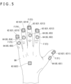
- FIG. 5 is a schematic diagram illustrating a positional relation between the user's hand, the position/posture detection section 62, and a vibration generation section 65.
- the operation device 6 includes the position/posture detection section 62, a proximity detection section 63, a stimulus generation section 64, and a control section 68 in addition to the mounting section 61.
- the position/posture detection section 62 is disposed on the mounting section 61 to detect the movement of the user's hand and fingers. As depicted in FIGS. 4 and 5 , the position/posture detection section 62 includes a plurality of first position detection sections 621 and a second position detection section 622. The plurality of first position detection sections 621 are disposed for the individual fingers F. The second position detection section 622 is disposed at a position other than those of the fingers F of the user's hand.
- the plurality of first position detection sections 621 are disposed on the mounting section 61, provided in correspondence with the fingertips of the individual fingers F, and positioned on the nail side of the individual fingers F. Specifically, as depicted in FIG. 5 , the first position detection sections 621 are provided for the individual fingers F to detect the positions of the first position detection sections 621 as the positions of the fingertips of the fingers F, which are detection targets.
- the plurality of first position detection sections 621 include first position detection sections 6211 to 6215.
- the first position detection section 6211 is disposed on a first finger F1 (thumb), the first position detection section 6212 is disposed on a second finger F2 (index finger), the first position detection section 6213 is disposed on a third finger F3 (middle finger), the first position detection section 6214 is disposed on a fourth finger F4 (ring finger), and the first position detection section 6215 is disposed on a fifth finger F5 (little finger).
- the second position detection section 622 is disposed on the mounting section 61, positioned in correspondence with the back of the hand BH, and configured to detect the position of the second position detection section 622 as the position of the back of the hand BH.
- the first position detection sections 621 and the second position detection section 622 each include a magnetic sensor whose resistance value varies with the strength and direction of the magnetic field that is generated outside the operation device 6 by the magnetic field generation device 5, which is a transmitter. Then, the position detection sections 621 and 622 each calculate the position and the posture, which are calculated on the basis of the result of detection by the magnetic sensor, as the position and the posture of the corresponding finger, and thus as the position and the posture of the hand and fingers.
- FIG. 6 is a schematic diagram illustrating a positional relation between the user's hand and the proximity detection section 63.
- the proximity detection section 63 is disposed on the mounting section 61 to detect the proximity of an object relative to the user's hand and fingers. Specifically, as depicted in FIGS. 4 and 6 , the proximity detection section 63 is formed by a proximity sensor that is disposed on the outer surface of the mounting section 61 and positioned on the ball side of the fingertip of each finger F. That is, the proximity detection section 63 disposed on the mounting section 61 is placed at a position corresponding to the ball of the fingertip of each finger F, which is a detection target. When the user attempts to grasp an object with the fingers F of the hand wearing the operation device 6, the proximity detection section 63 detects whether or not the object is brought into contact with the fingers, that is, whether or not the hand wearing the operation device 6 has grasped the object.
- the proximity sensor forming the proximity detection section 63 is provided for each of the user's fingers F1-F5.
- the proximity sensor may alternatively be provided on the palm PL and the back of the hand BH instead of the fingers F1-F5 or in addition to the fingers F1-F5.
- Another alternative is to provide the above-described tactile sensor instead of the proximity sensor.
- the stimulus generation section 64 depicted in FIG. 3 is disposed on the mounting section 61, and configured to operate based on a control signal received from the communication device 4, in order to apply an external stimulus to the user. That is, the stimulus generation section 64 artificially reproduces the stimulus to the puppet PP according to the control signal based on the result of detection by the detection section 22, which detects a stimulus acting on the puppet main body 2.
- the stimulus generation section 64 includes the vibration generation section 65, a temperature adjustment section 66, and a pressing section 67.
- the vibration generation section 65 applies a vibration to the user to create an illusion causing the user to feel as if an object is brought into contact with the user's hand and fingers.
- a plurality of vibration generation sections 65 may each include, for example, a voice coil motor.
- the vibration generation section 65 includes vibration generation sections 651 to 655 that are disposed on the mounting section 61 and placed at positions corresponding to the individual fingers.
- the vibration generation sections 652 to 655 are disposed on the mounting section 61 and placed at positions corresponding to the second finger F2, the third finger F3, the fourth finger F4, and the fifth finger F5. More specifically, the vibration generation sections 652 to 655 are disposed on the mounting section 61 and placed at positions between the first and second joints of the fingers F2 to F5.
- the vibration generation section 651 in the present embodiment is disposed at a position between the first joint of the first finger F1 and the joint at the base of the first finger, and the vibration generation sections 652 to 655 are disposed at positions between the first and second joints of each of the second finger F2, the third finger F3, the fourth finger F4, and the fifth finger F5.
- the pressing section 67 is disposed on the mounting section 61, placed at positions corresponding to the hand and fingers, and configured to press the user's hand and fingers. Although not depicted, the pressing section 67 is disposed on the mounting section 61 and placed at positions corresponding to the fingers F, at a position corresponding to the palm PL, and at a position corresponding to the back of the hand BH. More specifically, five out of a plurality of pressing sections 67, which are provided for the fingers F, are placed at positions corresponding to the fingertips of the fingers to be pressed, and configured to press the fingertips of the fingers F.
- the plurality of pressing sections 67 disposed on the mounting section 61 may be placed at positions corresponding to the palm PL and at positions corresponding to the back of the hand BH.
- Examples of the pressing section 67 may include a combination of an air pump and a silicone air chamber that is expanded or contracted by a gas supplied from the air pump, or a combination of a piezoelectric element and a pressing piece that is moved by the piezoelectric element to press the hand and fingers.
- the control section 68 controls the operation of the operation device 6.
- the control section 68 is electrically connected to the position/posture detection section 62, the proximity detection section 63, and the stimulus generation section 64.
- the control section 68 not only transmits an operation signal indicating the position and the posture of the hand and fingers, which are detected by the position/posture detection section 62, to the communication device 4, but also transmits a detection signal, which indicates the result of detection by the proximity detection section 63, to the communication device 4. Further, the control section 68 operates the vibration generation section 65, the temperature adjustment section 66, and the pressing section 67 of the stimulus generation section 64 according to the control signal received from the communication device 4.
- control section 68 is disposed on the mounting section 61 and placed at a position corresponding to the wrist of the user.
- the operation system 1 according to the present embodiment which has been described above, provides the following advantages.
- the operation system 1 includes the operation device 6 and the puppet main body 2, which operates according to the operation information based on the result of detection by the first position detection sections 621 of the operation device 6.
- the puppet main body 2 corresponds to the operation target.
- the configuration described above enables the first position detection sections 621 to detect the positions of the fingers F of the user wearing the operation device 6 and the postures of the fingers F. Further, the stimulus generation section 64 is able to apply an external stimulus to the user's fingers F. Therefore, based on the positions and the postures of the fingers F, which are detected by the first position detection sections 621, the external stimulus can be applied to the fingers F targeted for detection by the first position detection sections 621 or applied to the other fingers F. This increases the versatility of the operation device 6. Furthermore, the operation system 1 can be configured such that the operation target (e.g., the puppet main body 2) can be operated by the operation device 6, and that a stimulus externally applied to the operation target can be fed back to the user.
- the operation target e.g., the puppet main body 2
- the configuration described above eliminates the necessity of providing the first position detection sections 621 at the fingertips of the fingers F targeted for detection by the first position detection sections 621. Therefore, a higher degree of freedom can be provided for the fingertips targeted for position detection than in a case where the first position detection sections 621 are provided in correspondence with the fingertips of the fingers F targeted for position detection.
- the operation device 6 is configured such that the stimulus generation section 64 includes the vibration generation section 65.
- the vibration generation sections 652 to 655 which are included in the vibration generation section 65 disposed on the mounting section 61, are positioned between the first and second joints of the corresponding fingers to generate a vibration.
- the configuration described above makes it possible to transmit the vibration to the fingertips of the corresponding fingers F. Consequently, the same illusion can be given to the user as in the case of direct vibration of the fingertips.
- the operation device 6 includes the proximity detection section 63, which is disposed on the mounting section 61, positioned on the ball side of the user's fingertips, and configured to detect the proximity of an object.
- the configuration described above enables the proximity detection section 63 to accurately detect the proximity of an object relative to the user's fingertips.
- the operation device 6 is configured such that the stimulus generation section 64 includes the temperature adjustment section 66, which is able to adjust the temperature.
- the configuration described above makes it possible to give the user a cool sensation and a warm sensation. Consequently, the versatility of the operation device 6 can be increased, so that the user operating the operation device 6 is able to perceive the temperature indicative of contact between the operation target and another user or an object.
- the operation device 6 is configured such that the stimulus generation section 64 includes the pressing section 67, which presses the user's hand and fingers.
- the configuration described above enables the pressing section 67 to apply a reaction force to the user when the user grasps an object, and give the user a tactile sensation as if the user's hand is touched by another person.
- the operation device 6 includes the second position detection section 622, which is disposed on the mounting section 61, placed at a position corresponding to the back of the user's hand BH, and configured to detect the position of the back of the hand BH.
- the configuration described above enables the second position detection section 622 to detect the movement of turning the user's wrist. Consequently, the user's hand movements can be detected in detail.
- the operation device 6 is configured such that the mounting section 61 is shaped like a glove that is worn on the user's hand and fingers.
- the configuration described above ensures that the operation device 6 can easily be worn on the user's hand.
- the operation device 6 is configured such that the first position detection sections 621 include the magnetic sensor, which detects an externally generated magnetic field. The same applies to the second position detection section 622.
- the configuration described above makes it possible to detect the positions of the fingers F without interfering with the movement of the fingers F compared to the case where, for example, the first position detection sections 621 include an exoskeleton attached to the finger F and a movement amount detection device configured to detect the amount of movement of the exoskeleton.
- the operation device 6 includes the control section 68, which is disposed on the mounting section 61, placed at a position corresponding to the user's wrist, and configured to control the stimulus generation section 64.
- the configuration described above makes it possible to dispose the control section 68 at a position where hand movements are unlikely to be interfered with. This suppresses a decrease in the degree of freedom of the user's hand and fingers.
- the operation system according to the second embodiment is similar in configuration to the operation system 1 according to the first embodiment. However, there are some differences in configuration between the operation system according to the second embodiment and the operation system according to the first embodiment. Incidentally, in the following description, parts identical or substantially identical with already described parts are designated by the same reference signs as the corresponding parts and will not be redundantly described.
- FIG. 7 is a schematic diagram illustrating an operation device 7 included in the operation system according to the second embodiment.
- the operation system according to the second embodiment has the same configuration and functions as the operation system 1 according to the first embodiment, except that the former includes the operation device 7, which is depicted in FIG. 7 , instead of the operation device 6 according to the first embodiment.
- the operation system according to the second embodiment includes the puppet main body 2 disposed inside the puppet PP, the control device 3, the communication device 4, and the operation device 7.
- the operation device 7 communicates with the communication device 4 to remotely control the puppet main body 2, which has been described in conjunction with the first embodiment.
- the operation device 7 detects the movement of the user's hand and fingers, and transmits to the communication device 4 an operation signal corresponding to the detected movement of the hand and fingers. Additionally, the operation device 7 applies an external stimulus to the user according to a control signal received from the communication device 4.
- the operation device 7 has the same configuration and functions as the operation device 6 except that the former includes a stimulus generation section 64A instead of the stimulus generation section 64. That is, the operation device 7 includes the mounting section 61, the position/posture detection section 62, the proximity detection section 63, the stimulus generation section 64A, and the control section 68.
- the control section 68 is disposed on the mounting section 61 and placed at a position corresponding to the back of the hand BH.
- the control section 68 may alternatively be placed at a position corresponding to the user's wrist, as is the case with the control section 68 of the operation device 6 according to the first embodiment.
- the stimulus generation section 64A includes a reaction force generation section 71 in addition to the vibration generation section 65, the temperature adjustment section 66, and the pressing section 67, which are similarly included in the stimulus generation section 64 described in conjunction with the first embodiment.
- the reaction force generation section 71 generates a reaction force against the movement of the user's hand and fingers, causing the user to feel as if the hand and fingers are in contact with an object. Specifically, the reaction force generation section 71 generates a reaction force that restricts the movement of the user's fingers F, causing the user to feel as if the fingers F is in contact with an object.
- the reaction force generation section 71 includes a reaction force generation section 711, a reaction force generation section 712, a reaction force generation section 713, a reaction force generation section 714, and a reaction force generation section 715.
- the reaction force generation section 711 exerts a reaction force on the first finger F1.
- the reaction force generation section 712 exerts a reaction force on the second finger F2.
- the reaction force generation section 713 exerts a reaction force on the third finger F3.
- the reaction force generation section 714 exerts a reaction force on the fourth finger F4.
- the reaction force generation section 715 exerts a reaction force on the fifth finger F5.
- the reaction force generation sections 711-715 each include a link mechanism 72 and a resistance section 73.
- the link mechanism 72 connects the resistance section 73 to a finger F on which the reaction force is to be exerted.
- the link mechanism 72 includes a plurality of links that are bendably connected to each other, and is displaced according to the movement of the connected finger F.
- One end of the link mechanism 72 is connected to the fingertip of the finger F on which the reaction force is to be exerted, and the other end of the link mechanism 72 is connected to the resistance section 73.
- one end of the link mechanism 72 of the reaction force generation section 712 that exerts a reaction force on the second finger F2 is connected to the fingertip of the second finger F2, and the other end of the link mechanism 72 of the reaction force generation section 712 is connected to the resistance section 73 of the reaction force generation section 712.
- the operation device 7 is a generally-called exoskeleton controller.
- the resistance section 73 changes the resistance to the displacement of the link mechanism 72, which is displaced according to the movement of the finger F on which the reaction force is to be exerted, and thus exerts the reaction force against the movement of the finger F on the finger F.
- the resistance section 73 of the reaction force generation section 712 makes it difficult to bend the second finger F2 by increasing the resistance to the displacement of the link mechanism 72 that is displaced according to the bending motion of the second finger F2.
- the reaction force against the bending motion of the second finger F2 acts on the second finger F2. Therefore, the user is able to recognize the illusion that an object is in contact with the second finger F2.
- the operation system according to the second embodiment which has been described above, is able to provide the same advantages as the operation system 1 according to the first embodiment.
- a potentiometer or other displacement amount detection section for detecting the amount of displacement of the link mechanism 72 may be provided in place of the resistance section 73 in order to configure the reaction force generation section 71 as a first position detection section for detecting the position of the finger F targeted for position detection by detecting the movement of the finger F.
- the present invention is not limited to the foregoing embodiments, but includes modifications and improvements within a range where the purpose of the present invention can be achieved.
- the position/posture detection section 62 including the first position detection sections 621 and the second position detection section 622 is provided with a magnetic sensor that detects magnetism.
- the position/posture detection section may adopt an alternative method that is not based on the use of a magnetic sensor.
- the position/posture detection section 62 includes the first position detection sections 621 (6211 to 6215) and the second position detection section 622.
- the first position detection sections 621 (6211 to 6215) are disposed on the mounting section 61 and placed at positions corresponding to the fingertips of the fingers F targeted for detection.
- the second position detection section 622 is placed at a position corresponding to the back of the hand BH.
- the present invention is not limited to such configuration, but the position/posture detection section 62 may alternatively include at least one of the first position detection sections 6211 to 6215. Further, the second position detection section 622 need not necessarily be included in the position/posture detection section 62.
- first position detection sections 621 in the foregoing embodiments are disposed on the mounting section 61 and positioned on the nail side of the fingertips of the fingers F.
- the present invention is not limited to such configuration, but the first position detection sections may be disposed at any positions where the first position detection sections are able to detect the positions of the fingers F.
- the vibration generation sections 652 to 655 provided for the second finger F2, the third finger F3, the fourth finger F4, and the fifth finger F5 are disposed on the mounting section 61 and positioned between the first and second joints of the individual fingers F.
- the present invention is not limited to such configuration, but the vibration generation sections 652 to 655 may alternatively be placed at other positions. Further, the vibration generation section 65 need not necessarily be provided.
- the operation devices 6 and 7 include the proximity detection section 63, which is disposed on the mounting section 61 and positioned on the ball side of the user's fingertips.
- the proximity detection section 63 need not necessarily be included in the operation devices 6 and 7.
- the proximity detection section 63, which is disposed on the mounting section 61 need not necessarily be positioned on the ball side of the user's fingertips. The position of the proximity detection section 63 may be changed as appropriate.
- the stimulus generation section 64 includes the temperature adjustment section 66. That is, the operation devices 6 and 7 in the foregoing embodiments includes the temperature adjustment section 66, which is able to adjust the temperature.
- the present invention is not limited to such a configuration.
- the temperature adjustment section 66 need not necessarily be included in the operation devices 6 and 7. Further, the position of the temperature adjustment section 66 is not limited to the one described above, but may be different from the above-described one.
- the stimulus generation section 64 includes the pressing section 67. That is, the operation devices 6 and 7 are provided with the pressing section 67 that presses the user's hand and fingers.
- the present invention is not limited to such configuration.
- the pressing section 67 need not necessarily be provided. Further, the position of the pressing section 67 is not limited to the one described above, but may be different from the above-described one.
- the operation devices 6 and 7 is disposed on the mounting section 61, placed at a position corresponding to the back of the user's hand BH, and provided with the second position detection section 622, which detects the position of the back of the hand BH.
- the present invention is not limited to such configuration.
- the second position detection section 622 need not necessarily be provided.
- the mounting section 61 is shaped like a glove that is worn on the user's hand and fingers.
- the mounting section 61 need not necessarily be shaped like a glove.
- the shape of the mounting section 61 may be changed as appropriate as long as the component elements of the operation devices 6 and 7 can be disposed on the mounting section 61.
- the mounting section 61 may be shaped like a band or may be similar in shape to the puppet PP.
- the operation device 6 is disposed on the mounting section 61, placed at a position corresponding to the user's wrist, and provided with the control section 68, which controls the stimulus generation section 64.
- the present invention is not limited to such configuration.
- the control section 68 need not necessarily be provided.
- the control section 68 may be disposed on the mounting section 61 and placed at a position corresponding to the back of the hand or at another position. That is, the position of the control section 68 may be changed as appropriate, and may be a position other than the user's hand and fingers.
- the operation system is formed by the operation devices 6 and 7 and the operation target (e.g., the puppet main body 2), which operates according to the operation information based on the result of detection by the position/posture detection section 62.
- the present invention is not limited to such configuration.
- the operation target of the operation devices 6 and 7 need not necessarily be the puppet main body 2, but may be another component element.
- the operation target may alternatively be, for example, a robot hand or a manipulator.
- the operation devices 6 and 7 operate the puppet main body 2 through the control device 3 and the communication device 4, which use the network NT to communicate with the operation devices 6 and 7.
- the present invention is not limited to such configuration.
- the operation devices 6 and 7 may directly operate the puppet main body 2, which is the operation target.
- the present invention is outlined below.
- the configuration described above enables the first position detection section to detect the positions of the fingers of the user wearing the operation device and the postures of the fingers. Further, the stimulus generation section is able to apply an external stimulus to the user's fingers. Therefore, based on the positions and the postures of the fingers, which are detected by the first position detection section, the external stimulus can be applied to the fingers targeted for position detection by the first position detection section or applied to the other fingers. This increases the versatility of the operation device.
- the operation device described in [1] above may be configured such that the first position detection section is disposed on the mounting section and positioned on a nail side of the user's fingertips.
- the configuration described above eliminates the necessity of providing the first position detection section at the fingertips of the fingers targeted for position detection by the first position detection section. Therefore, a higher degree of freedom can be provided for the fingertips targeted for position detection than in a case where the first position detection section is provided in correspondence with the fingertips of the fingers targeted for position detection.
- the operation device described in [1] or [2] above may be configured such that the stimulus generation section includes the vibration generation section, which is disposed on the mounting section, positioned between the first and second joints of the user's fingers, and configured to generate a vibration.
- the configuration described above makes it possible to transmit the vibration to the fingertips and give the same illusion to the user as in the case of direct vibration of the fingertips. This eliminates the necessity of providing the vibration generation section at the fingertips. Therefore, a higher degree of freedom can be provided for the fingertips than in a case where the vibration generation section is disposed at the fingertips.
- the operation device described in any one of [1] to [3] above may include the proximity detection section, which is disposed on the mounting section, positioned on a ball side of the user's fingertips, and configured to detect the proximity of an object.
- the proximity detection section for detecting the proximity of an object is disposed on the ball side of the fingertips, the configuration described above enables the proximity detection section to accurately detect the proximity of an object relative to the user's fingertips.
- the operation device described in any one of [1] to [4] above may be configured such that the stimulus generation section includes the temperature adjustment section, which is able to adjust the temperature.
- the configuration described above makes it possible to give the user a cool sensation and a warm sensation. Consequently, the versatility of the operation device can be increased, so that the user operating the operation device is able to perceive the temperature indicative of contact between the operation target, which is operated by the operation device, and another user or an object.
- the operation device described in any one of [1] to [5] above may be configured such that the stimulus generation section includes the pressing section, which presses the user's hand and fingers.
- the configuration described above enables the pressing section to apply a reaction force to the user when the user grasps an object, and give the user a tactile sensation as if the user's hand is touched by another person. Consequently, the versatility of the operation device can be increased.
- the second position detection section which is disposed on the mounting section, placed at a position corresponding to a back of the user's hand, and configured to detect a position of the back of the hand.
- the configuration described above enables the second position detection section to detect the movement of turning the user's wrist. Consequently, the user's hand movements can be detected in detail.
- the operation device described in any one of [1] to [7] above may be configured such that the mounting section is shaped like a glove that is worn on the user's hand and fingers.
- the operation device described in any one of [1] to [8] above may be configured such that the first position detection section includes the magnetic sensor, which detects an externally generated magnetic field.
- the configuration described above makes it possible to detect the positions of the fingers without interfering with the movement of the fingers compared to the case where, for example, the first position detection section includes an exoskeleton attached to the fingers and a movement amount detection device configured to detect the amount of movement of the exoskeleton.
- the operation device described in any one of [1] to [9] above may include the control section, which is disposed on the mounting section, placed at a position corresponding to the user's wrist, and configured to control the stimulus generation section.
- the configuration described above makes it possible to dispose the control section at a position where hand movements are unlikely to be interfered with. This suppresses a decrease in the degree of freedom of the user's hand and fingers.
- the operation system includes the operation device described in any one of [1] to [10] above and the operation target configured to operate according to operation information based on the result of detection by the first position detection section.
Landscapes
- Engineering & Computer Science (AREA)
- General Engineering & Computer Science (AREA)
- Theoretical Computer Science (AREA)
- Human Computer Interaction (AREA)
- Physics & Mathematics (AREA)
- General Physics & Mathematics (AREA)
- User Interface Of Digital Computer (AREA)
- Mechanical Control Devices (AREA)
- Position Input By Displaying (AREA)
Abstract
Description
- The present invention relates to an operation device and an operation system.
- In the past, a hand puppet manipulation system that includes a puppet operation device and a control module (refer, for example, to PTL 1) has been known. The puppet operation device is mounted inside a hand puppet to operate the hand puppet. The control module remotely controls the puppet operation device.
- The control module included in the hand puppet manipulation system described in
PTL 1 is used while being fitted in a hand of a user, and includes a data glove that detects the movement of the user's hand. The data glove includes multiple types of sensors for measuring physical quantities that vary with the movement of the user's hand. Data concerning physical quantities measured by the data glove is transmitted to a conversion module, and converted to various control signals by the conversion module. The control signals resulting from conversion are transmitted to the puppet operation device. The puppet operation device then operates the hand puppet according to the control signals. - [PTL 1]
Japanese Patent Laid-open No. 2010-89248 - In recent years, there has been a demand for a more realistic operational feeling.
- However, the hand puppet manipulation system described in
PTL 1 has a problem in that the user operating the control module is unable to sense the stimulus applied to the puppet operation device. - According to a first aspect of the present invention, there is provided an operation device including a mounting section, a first position detection section, and a stimulus generation section. The mounting section is attached to a hand and fingers of a user. The first position detection section is disposed on the mounting section to detect the positions of the user's fingers. The stimulus generation section is disposed on the mounting section, placed at a position corresponding to one of the user's fingers, and configured to apply an external stimulus to the user.
- According to a second aspect of the present invention, there is provided an operation system that includes an operation device according to the first aspect and an operation target. The operation target operates according to operation information based on the result of detection by the first position detection section.
-
- [
FIG. 1 ]
FIG. 1 is a schematic diagram illustrating an outline configuration of an operation system according to a first embodiment. - [
FIG. 2 ]
FIG. 2 is a block diagram illustrating a configuration of a puppet main body and a configuration of a control device according to the first embodiment. - [
FIG. 3 ]
FIG. 3 is a block diagram illustrating a configuration of a communication device and a configuration of an operation device according to the first embodiment. - [
FIG. 4 ]
FIG. 4 is a perspective view schematically illustrating the operation device according to the first embodiment. - [
FIG. 5 ]
FIG. 5 is a schematic diagram illustrating a positional relation between a hand of a user, a position/posture detection section, and a vibration generation section according to the first embodiment. - [
FIG. 6 ]
FIG. 6 is a schematic diagram illustrating a positional relation between the user's hand and a proximity detection section according to the first embodiment. - [
FIG. 7 ]
FIG. 7 is a perspective view schematically illustrating the operation device included in the operation system according to a second embodiment. - A first embodiment of the present invention will now be described with reference to the accompanying drawings.
-
FIG. 1 is a schematic diagram illustrating an outline configuration of anoperation system 1 according to the first embodiment. - As depicted in
FIG. 1 , theoperation system 1 according to the present embodiment includes a puppetmain body 2, acontrol device 3, acommunication device 4, a magneticfield generation device 5, and anoperation device 6. The puppetmain body 2 is attached to a puppet PP. In theoperation system 1, theoperation device 6 remotely controls the puppetmain body 2 through thecontrol device 3 and thecommunication device 4, and causes a user to perceive a stimulus detected by the puppetmain body 2. - It should be noted that the puppet PP is a hollow doll having a torso PP1, a head PP2, a right arm PP3, and a left arm PP4, and is made, for example, by cloth.
- Further, the magnetic
field generation device 5 generates a magnetic field that is detected by a later-described position/posture detection section 62 of theoperation device 6. - The puppet
main body 2 is an operation target to be operated by theoperation device 6. The puppetmain body 2 is inserted into the puppet PP to operate the puppet PP. Further, the puppetmain body 2 can be said to be an operation device that is operated by a user other than the user using theoperation device 6 for the purpose of applying an external stimulus to the user through theoperation device 6. - As depicted in
FIG. 1 , the puppetmain body 2 includes adrive section 21. - The
drive section 21 operates according to a control signal inputted from thecontrol device 3. Thedrive section 21 operates the head PP2, the right arm PP3, and the left arm PP4. Thedrive section 21 includes asupport section 211, ahead drive section 212, a right-arm drive section 213, and a left-arm drive section 214. - The
support section 211 is provided in correspondence with the torso PP1 to support thehead drive section 212, the right-arm drive section 213, and the left-arm drive section 214. - The
head drive section 212 bends or extends the head PP2. The right-arm drive section 213 bends or extends the right arm PP3. The left-arm drive section 214 bends or extends the left arm PP4. Thedrive sections 212 to 214 may be exemplified as having a plurality of links and a motor. The plurality of links are configured to be bendable with respect to each other. The motor is configured to operate the plurality of links. -
FIG. 2 is a block diagram illustrating a configuration of the puppetmain body 2 and a configuration of thecontrol device 3. - As depicted in
FIG. 2 , the puppetmain body 2 includes adetection section 22. - The
detection section 22 detects a stimulus acting on the puppetmain body 2, and outputs the result of detection to thecontrol device 3. Thedetection section 22 includes atactile sensor 23 and atemperature sensor 24. - The
tactile sensor 23 detects proximity of an object without contact. Further, when the object comes into contact with thetactile sensor 23, thetactile sensor 23 detects the pressure applied to the object. Stated differently, thetactile sensor 23 detects the pressure exerted by the object brought into contact with thetactile sensor 23. Thetactile sensor 23 provided, for example, for the puppetmain body 2 is placed at a position corresponding to each of the torso PP1, the head PP2, the tip of the right arm PP3, and the tip of the left arm PP4. Thetactile sensor 23 transmits the result of detection to thecontrol device 3. It should be noted that thetactile sensor 23 functions as a proximity sensor for detecting the proximity of an object, and additionally functions as a pressure sensor for detecting a pressure. However, thetactile sensor 23 need not necessarily have such two functions. Thetactile sensor 23 may have either the function of the proximity sensor or the function of the pressure sensor. Furthermore, at least either the proximity sensor or the pressure sensor may be provided instead of thetactile sensor 23. - The
temperature sensor 24 detects a temperature. Thetemperature sensor 24 provided, for example, for the puppetmain body 2 is placed at a position corresponding to each of the torso PP1, the head PP2, the right arm PP3, and the left arm PP4, and transmits the detected temperature to thecontrol device 3. - The
control device 3 controls the operation of the puppetmain body 2. Specifically, thecontrol device 3 drives thedrive section 21 according to operation information received from thecommunication device 4, in order to operate the puppetmain body 2 and thus operate the puppet PP. As depicted inFIG. 2 , thecontrol device 3 includes acommunication section 31, astorage section 32, and acontrol section 33. - The
communication section 31 not only communicates with the puppetmain body 2, but also communicates with thecommunication device 4 through a network NT. Under the control of thecontrol section 33, thecommunication section 31 not only outputs the operation information, which is received from thecommunication device 4, to thecontrol section 33, but also transmits detected information, which indicates the result of detection by thedetection section 22 of the puppetmain body 2, to thecommunication device 4. It should be noted that thecommunication section 31 may be connected to the puppetmain body 2 by wire or by a communication method compliant with wireless communication standards such as Bluetooth (registered trademark) and IEEE (Institute of Electrical and Electronics Engineers) 802.11. - The
storage section 32 stores programs and data necessary for the operation of thecontrol device 3. For example, thestorage section 32 stores information regarding the connection to thecommunication device 4, information indicating the type of the puppetmain body 2, and an operation program for operating the puppetmain body 2 according to the received operation information. - The
control section 33 includes an arithmetic processing circuit such as a CPU (Central Processing Unit), and controls the operation of the puppetmain body 2 according to a program stored in thestorage section 32. Specifically, thecontrol section 33 transmits to the puppetmain body 2 through the communication section 31 a control signal for operating thedrive section 21 of the puppetmain body 2 according to the operation information received from thecommunication device 4. Further, thecontrol section 33 causes thecommunication section 31 to transmit the detected information which indicates the result of detection by thedetection section 22 of the puppetmain body 2, to thecommunication device 4. -
FIG. 3 is a block diagram illustrating a configuration of thecommunication device 4 and a configuration of theoperation device 6. - As depicted in
FIG. 1 , thecommunication device 4 not only transmits the operation information based on an operation signal inputted from theoperation device 6, but also operates theoperation device 6 according to the detected information received from thecontrol device 3. That is, thecommunication device 4 acts as an operation device control device that controls some component elements included in theoperation device 6. As depicted inFIG. 3 , thecommunication device 4 includes acommunication section 41, astorage section 42, and acontrol section 43. - The
communication section 41 not only communicates with theoperation device 6, but also communicates with thecontrol device 3 through the network NT. Under the control of thecontrol section 43, thecommunication section 41 not only outputs the detected information, which is received from thecontrol device 3, to thecontrol section 43, but also transmits the operation information, which is based on the operation signal received from theoperation device 6, to thecontrol device 3. It should be noted that thecommunication section 41 may be connected to theoperation device 6 by wire or by a communication method compliant with wireless communication standards such as Bluetooth (registered trademark) and IEEE 802.11. - The
storage section 42 stores programs and data necessary for the operation of thecommunication device 4. For example, thestorage section 42 stores a conversion program for converting the operation signal received from theoperation device 6 to operation information suitable for causing thecontrol device 3 to operate the puppetmain body 2. Further, for example, thestorage section 42 stores connection information for connecting to thecontrol device 3 that controls the puppetmain body 2, which is an operation target to be operated by theoperation device 6. Therefore, in a case where multiple pairs ofcontrol device 3 and puppetmain body 2 are connected to the network NT, thestorage section 42 stores the connection information for eachcontrol device 3. - The
control section 43 converts the operation signal which is received from theoperation device 6 to the above-mentioned operation information according to the conversion program, and causes thecommunication section 41 to transmit the operation information to thecontrol device 3. Further, thecontrol section 43 generates a control signal for operating theoperation device 6 according to the detected information which is received from thecontrol device 3 by thecommunication section 41, and transmits the generated control signal to theoperation device 6 in order to control some component elements included in theoperation device 6. - The
operation device 6 remotely controls the puppetmain body 2. Specifically, theoperation device 6 detects the movement of the user, transmits an operation signal corresponding to the detected movement of the user to thecommunication device 4, and causes thecommunication device 4 and thecontrol device 3 to operate the puppetmain body 2. In the present embodiment, theoperation device 6 detects the movement of a hand and fingers of the user. Further, theoperation device 6 applies an external stimulus to the user in response to a control signal that is received from thecommunication device 4 according to the result of detection by thedetection section 22 of the puppetmain body 2. -
FIG. 4 is a perspective view schematically illustrating theoperation device 6. - As depicted in
FIG. 4 , theoperation device 6 includes a mountingsection 61 that is attached to one hand of the user. The mountingsection 61 is shaped like a glove and worn on the fingers of one hand of the user. Therefore, the user can also wear a puppet similar to the puppet PP on the user's hand so as to cover the outside of theoperation device 6 while wearing theoperation device 6 on the user's hand. The mountingsection 61 is preferably formed by a stretchable material that can be firmly attached to the user's hand. -
FIG. 5 is a schematic diagram illustrating a positional relation between the user's hand, the position/posture detection section 62, and avibration generation section 65. As depicted inFIG. 3 , theoperation device 6 includes the position/posture detection section 62, aproximity detection section 63, astimulus generation section 64, and acontrol section 68 in addition to the mountingsection 61. - The position/
posture detection section 62 is disposed on the mountingsection 61 to detect the movement of the user's hand and fingers. As depicted inFIGS. 4 and5 , the position/posture detection section 62 includes a plurality of firstposition detection sections 621 and a secondposition detection section 622. The plurality of firstposition detection sections 621 are disposed for the individual fingers F. The secondposition detection section 622 is disposed at a position other than those of the fingers F of the user's hand. - The plurality of first
position detection sections 621 are disposed on the mountingsection 61, provided in correspondence with the fingertips of the individual fingers F, and positioned on the nail side of the individual fingers F. Specifically, as depicted inFIG. 5 , the firstposition detection sections 621 are provided for the individual fingers F to detect the positions of the firstposition detection sections 621 as the positions of the fingertips of the fingers F, which are detection targets. The plurality of firstposition detection sections 621 include firstposition detection sections 6211 to 6215. - The first
position detection section 6211 is disposed on a first finger F1 (thumb), the firstposition detection section 6212 is disposed on a second finger F2 (index finger), the firstposition detection section 6213 is disposed on a third finger F3 (middle finger), the firstposition detection section 6214 is disposed on a fourth finger F4 (ring finger), and the firstposition detection section 6215 is disposed on a fifth finger F5 (little finger). - The second
position detection section 622 is disposed on the mountingsection 61, positioned in correspondence with the back of the hand BH, and configured to detect the position of the secondposition detection section 622 as the position of the back of the hand BH. - In the present embodiment, the first
position detection sections 621 and the secondposition detection section 622 each include a magnetic sensor whose resistance value varies with the strength and direction of the magnetic field that is generated outside theoperation device 6 by the magneticfield generation device 5, which is a transmitter. Then, theposition detection sections -
FIG. 6 is a schematic diagram illustrating a positional relation between the user's hand and theproximity detection section 63. - The
proximity detection section 63 is disposed on the mountingsection 61 to detect the proximity of an object relative to the user's hand and fingers. Specifically, as depicted inFIGS. 4 and6 , theproximity detection section 63 is formed by a proximity sensor that is disposed on the outer surface of the mountingsection 61 and positioned on the ball side of the fingertip of each finger F. That is, theproximity detection section 63 disposed on the mountingsection 61 is placed at a position corresponding to the ball of the fingertip of each finger F, which is a detection target. When the user attempts to grasp an object with the fingers F of the hand wearing theoperation device 6, theproximity detection section 63 detects whether or not the object is brought into contact with the fingers, that is, whether or not the hand wearing theoperation device 6 has grasped the object. - In the present embodiment, the proximity sensor forming the
proximity detection section 63 is provided for each of the user's fingers F1-F5. However, the proximity sensor may alternatively be provided on the palm PL and the back of the hand BH instead of the fingers F1-F5 or in addition to the fingers F1-F5. Another alternative is to provide the above-described tactile sensor instead of the proximity sensor. - The
stimulus generation section 64 depicted inFIG. 3 is disposed on the mountingsection 61, and configured to operate based on a control signal received from thecommunication device 4, in order to apply an external stimulus to the user. That is, thestimulus generation section 64 artificially reproduces the stimulus to the puppet PP according to the control signal based on the result of detection by thedetection section 22, which detects a stimulus acting on the puppetmain body 2. - The
stimulus generation section 64 includes thevibration generation section 65, atemperature adjustment section 66, and apressing section 67. - The
vibration generation section 65 applies a vibration to the user to create an illusion causing the user to feel as if an object is brought into contact with the user's hand and fingers. A plurality ofvibration generation sections 65 may each include, for example, a voice coil motor. - In the present embodiment, as depicted in
FIGS. 4 and5 , thevibration generation section 65 includesvibration generation sections 651 to 655 that are disposed on the mountingsection 61 and placed at positions corresponding to the individual fingers. - The
vibration generation section 651 is disposed on the mountingsection 61 and placed at a position between the first joint of the first finger F1 and the joint at the base of the first finger. - The
vibration generation sections 652 to 655 are disposed on the mountingsection 61 and placed at positions corresponding to the second finger F2, the third finger F3, the fourth finger F4, and the fifth finger F5. More specifically, thevibration generation sections 652 to 655 are disposed on the mountingsection 61 and placed at positions between the first and second joints of the fingers F2 to F5. - When a vibration is directly applied to a fingertip in the above situation, the user is likely to have the illusion that an object is brought into contact with the fingertip to which the vibration is applied. However, disposing the
vibration generation sections 65, which are relatively large in size, on the fingertips is difficult and reduces the operability of theoperation device 6. Theoperation device 6 according to the present embodiment is configured such that theproximity detection section 63 and thetemperature adjustment section 66 are disposed on the fingertips. Therefore, a space for disposing thevibration generation sections 65 cannot easily be provided at the fingertips. - Meanwhile, the
vibration generation section 651 in the present embodiment is disposed at a position between the first joint of the first finger F1 and the joint at the base of the first finger, and thevibration generation sections 652 to 655 are disposed at positions between the first and second joints of each of the second finger F2, the third finger F3, the fourth finger F4, and the fifth finger F5. - Consequently, when a vibration is generated, for example, by the
vibration generation section 652, the vibration is transmitted to the fingertip of the second finger F2, giving the user the illusion that the vibration is directly applied to the fingertip of the second finger F2. As described above, thevibration generation sections 651 to 655 can be disposed at positions other than the fingertips. As a result, a vibration can be applied to the fingertip of each finger F. - The
temperature adjustment section 66 depicted inFIG. 3 is disposed on the mountingsection 61, placed at positions corresponding to the hand and fingers, and configured to give the user a warm sensation and a cool sensation. Although detailed illustrations are omitted, thetemperature adjustment section 66 is disposed on the mountingsection 61 and placed, for example, at a position corresponding to the fingertip of each finger F, at a position corresponding to the palm PL, and at a position corresponding to the back of the hand BH. Thetemperature adjustment section 66 is positioned inside the mountingsection 61. Thetemperature adjustment section 66 may be formed, for example, by a thermoelectric conversion element such as a Peltier element. - The
pressing section 67 is disposed on the mountingsection 61, placed at positions corresponding to the hand and fingers, and configured to press the user's hand and fingers. Although not depicted, thepressing section 67 is disposed on the mountingsection 61 and placed at positions corresponding to the fingers F, at a position corresponding to the palm PL, and at a position corresponding to the back of the hand BH. More specifically, five out of a plurality ofpressing sections 67, which are provided for the fingers F, are placed at positions corresponding to the fingertips of the fingers to be pressed, and configured to press the fingertips of the fingers F. It should be noted that the plurality ofpressing sections 67 disposed on the mountingsection 61 may be placed at positions corresponding to the palm PL and at positions corresponding to the back of the hand BH. Examples of thepressing section 67 may include a combination of an air pump and a silicone air chamber that is expanded or contracted by a gas supplied from the air pump, or a combination of a piezoelectric element and a pressing piece that is moved by the piezoelectric element to press the hand and fingers. - The
control section 68 controls the operation of theoperation device 6. Thecontrol section 68 is electrically connected to the position/posture detection section 62, theproximity detection section 63, and thestimulus generation section 64. Thecontrol section 68 not only transmits an operation signal indicating the position and the posture of the hand and fingers, which are detected by the position/posture detection section 62, to thecommunication device 4, but also transmits a detection signal, which indicates the result of detection by theproximity detection section 63, to thecommunication device 4. Further, thecontrol section 68 operates thevibration generation section 65, thetemperature adjustment section 66, and thepressing section 67 of thestimulus generation section 64 according to the control signal received from thecommunication device 4. - In the present embodiment, as depicted in
FIG. 5 , thecontrol section 68 is disposed on the mountingsection 61 and placed at a position corresponding to the wrist of the user. - The
operation system 1 according to the present embodiment, which has been described above, provides the following advantages. - The
operation system 1 includes theoperation device 6 and the puppetmain body 2, which operates according to the operation information based on the result of detection by the firstposition detection sections 621 of theoperation device 6. The puppetmain body 2 corresponds to the operation target. - The
operation device 6 includes the mountingsection 61, the firstposition detection sections 621, and thestimulus generation section 64. The mountingsection 61 is attached to the user's hand and fingers. The firstposition detection sections 621 are disposed on the mountingsection 61 to detect the positions of the corresponding fingers F. Thestimulus generation section 64 is disposed on the mountingsection 61, placed at a position corresponding to one of the user's fingers F, and configured to apply an external stimulus to the user. - The configuration described above enables the first
position detection sections 621 to detect the positions of the fingers F of the user wearing theoperation device 6 and the postures of the fingers F. Further, thestimulus generation section 64 is able to apply an external stimulus to the user's fingers F. Therefore, based on the positions and the postures of the fingers F, which are detected by the firstposition detection sections 621, the external stimulus can be applied to the fingers F targeted for detection by the firstposition detection sections 621 or applied to the other fingers F. This increases the versatility of theoperation device 6. Furthermore, theoperation system 1 can be configured such that the operation target (e.g., the puppet main body 2) can be operated by theoperation device 6, and that a stimulus externally applied to the operation target can be fed back to the user. - The
operation device 6 is configured such that the firstposition detection sections 621 are disposed on the mountingsection 61 and positioned on the nail side of the user's fingertips. - The configuration described above eliminates the necessity of providing the first
position detection sections 621 at the fingertips of the fingers F targeted for detection by the firstposition detection sections 621. Therefore, a higher degree of freedom can be provided for the fingertips targeted for position detection than in a case where the firstposition detection sections 621 are provided in correspondence with the fingertips of the fingers F targeted for position detection. - The
operation device 6 is configured such that thestimulus generation section 64 includes thevibration generation section 65. Thevibration generation sections 652 to 655, which are included in thevibration generation section 65 disposed on the mountingsection 61, are positioned between the first and second joints of the corresponding fingers to generate a vibration. - In a case where the vibration is generated by the
vibration generation sections 652 to 655, which are positioned as described above, the configuration described above makes it possible to transmit the vibration to the fingertips of the corresponding fingers F. Consequently, the same illusion can be given to the user as in the case of direct vibration of the fingertips. This eliminates the necessity of providing thevibration generation section 65 at the fingertips. Therefore, a higher degree of freedom can be provided for the fingertips than in a case where thevibration generation section 65 is disposed at the fingertips. - The
operation device 6 includes theproximity detection section 63, which is disposed on the mountingsection 61, positioned on the ball side of the user's fingertips, and configured to detect the proximity of an object. - The configuration described above enables the
proximity detection section 63 to accurately detect the proximity of an object relative to the user's fingertips. - The
operation device 6 is configured such that thestimulus generation section 64 includes thetemperature adjustment section 66, which is able to adjust the temperature. - The configuration described above makes it possible to give the user a cool sensation and a warm sensation. Consequently, the versatility of the
operation device 6 can be increased, so that the user operating theoperation device 6 is able to perceive the temperature indicative of contact between the operation target and another user or an object. - The
operation device 6 is configured such that thestimulus generation section 64 includes thepressing section 67, which presses the user's hand and fingers. - The configuration described above enables the
pressing section 67 to apply a reaction force to the user when the user grasps an object, and give the user a tactile sensation as if the user's hand is touched by another person. - The
operation device 6 includes the secondposition detection section 622, which is disposed on the mountingsection 61, placed at a position corresponding to the back of the user's hand BH, and configured to detect the position of the back of the hand BH. - The configuration described above enables the second
position detection section 622 to detect the movement of turning the user's wrist. Consequently, the user's hand movements can be detected in detail. - The
operation device 6 is configured such that the mountingsection 61 is shaped like a glove that is worn on the user's hand and fingers. - The configuration described above ensures that the
operation device 6 can easily be worn on the user's hand. - The
operation device 6 is configured such that the firstposition detection sections 621 include the magnetic sensor, which detects an externally generated magnetic field. The same applies to the secondposition detection section 622. - The configuration described above makes it possible to detect the positions of the fingers F without interfering with the movement of the fingers F compared to the case where, for example, the first
position detection sections 621 include an exoskeleton attached to the finger F and a movement amount detection device configured to detect the amount of movement of the exoskeleton. - The
operation device 6 includes thecontrol section 68, which is disposed on the mountingsection 61, placed at a position corresponding to the user's wrist, and configured to control thestimulus generation section 64. - The configuration described above makes it possible to dispose the
control section 68 at a position where hand movements are unlikely to be interfered with. This suppresses a decrease in the degree of freedom of the user's hand and fingers. - A second embodiment of the present invention will now be described.
- The operation system according to the second embodiment is similar in configuration to the
operation system 1 according to the first embodiment. However, there are some differences in configuration between the operation system according to the second embodiment and the operation system according to the first embodiment. Incidentally, in the following description, parts identical or substantially identical with already described parts are designated by the same reference signs as the corresponding parts and will not be redundantly described. -
FIG. 7 is a schematic diagram illustrating an operation device 7 included in the operation system according to the second embodiment. - The operation system according to the second embodiment has the same configuration and functions as the
operation system 1 according to the first embodiment, except that the former includes the operation device 7, which is depicted inFIG. 7 , instead of theoperation device 6 according to the first embodiment. The operation system according to the second embodiment includes the puppetmain body 2 disposed inside the puppet PP, thecontrol device 3, thecommunication device 4, and the operation device 7. - As is the case with the
operation device 6, the operation device 7 communicates with thecommunication device 4 to remotely control the puppetmain body 2, which has been described in conjunction with the first embodiment. The operation device 7 detects the movement of the user's hand and fingers, and transmits to thecommunication device 4 an operation signal corresponding to the detected movement of the hand and fingers. Additionally, the operation device 7 applies an external stimulus to the user according to a control signal received from thecommunication device 4. - The operation device 7 has the same configuration and functions as the
operation device 6 except that the former includes astimulus generation section 64A instead of thestimulus generation section 64. That is, the operation device 7 includes the mountingsection 61, the position/posture detection section 62, theproximity detection section 63, thestimulus generation section 64A, and thecontrol section 68. In the example ofFIG. 7 , thecontrol section 68 is disposed on the mountingsection 61 and placed at a position corresponding to the back of the hand BH. However, thecontrol section 68 may alternatively be placed at a position corresponding to the user's wrist, as is the case with thecontrol section 68 of theoperation device 6 according to the first embodiment. - The
stimulus generation section 64A includes a reactionforce generation section 71 in addition to thevibration generation section 65, thetemperature adjustment section 66, and thepressing section 67, which are similarly included in thestimulus generation section 64 described in conjunction with the first embodiment. - The reaction
force generation section 71 generates a reaction force against the movement of the user's hand and fingers, causing the user to feel as if the hand and fingers are in contact with an object. Specifically, the reactionforce generation section 71 generates a reaction force that restricts the movement of the user's fingers F, causing the user to feel as if the fingers F is in contact with an object. The reactionforce generation section 71 includes a reactionforce generation section 711, a reactionforce generation section 712, a reactionforce generation section 713, a reactionforce generation section 714, and a reactionforce generation section 715. The reactionforce generation section 711 exerts a reaction force on the first finger F1. The reactionforce generation section 712 exerts a reaction force on the second finger F2. The reactionforce generation section 713 exerts a reaction force on the third finger F3. The reactionforce generation section 714 exerts a reaction force on the fourth finger F4. The reactionforce generation section 715 exerts a reaction force on the fifth finger F5. - The reaction force generation sections 711-715 each include a
link mechanism 72 and aresistance section 73. - The
link mechanism 72 connects theresistance section 73 to a finger F on which the reaction force is to be exerted. Thelink mechanism 72 includes a plurality of links that are bendably connected to each other, and is displaced according to the movement of the connected finger F. One end of thelink mechanism 72 is connected to the fingertip of the finger F on which the reaction force is to be exerted, and the other end of thelink mechanism 72 is connected to theresistance section 73. For example, one end of thelink mechanism 72 of the reactionforce generation section 712 that exerts a reaction force on the second finger F2 is connected to the fingertip of the second finger F2, and the other end of thelink mechanism 72 of the reactionforce generation section 712 is connected to theresistance section 73 of the reactionforce generation section 712. As described above, the operation device 7 is a generally-called exoskeleton controller. - Under the control of the
control section 68, theresistance section 73 changes the resistance to the displacement of thelink mechanism 72, which is displaced according to the movement of the finger F on which the reaction force is to be exerted, and thus exerts the reaction force against the movement of the finger F on the finger F. For example, when the second finger F2 bends, theresistance section 73 of the reactionforce generation section 712 makes it difficult to bend the second finger F2 by increasing the resistance to the displacement of thelink mechanism 72 that is displaced according to the bending motion of the second finger F2. As a result, the reaction force against the bending motion of the second finger F2 acts on the second finger F2. Therefore, the user is able to recognize the illusion that an object is in contact with the second finger F2. - The operation system according to the second embodiment, which has been described above, is able to provide the same advantages as the
operation system 1 according to the first embodiment. - It should be noted that a potentiometer or other displacement amount detection section for detecting the amount of displacement of the
link mechanism 72 may be provided in place of theresistance section 73 in order to configure the reactionforce generation section 71 as a first position detection section for detecting the position of the finger F targeted for position detection by detecting the movement of the finger F. - The present invention is not limited to the foregoing embodiments, but includes modifications and improvements within a range where the purpose of the present invention can be achieved.
- In the foregoing embodiments, the position/
posture detection section 62 including the firstposition detection sections 621 and the secondposition detection section 622 is provided with a magnetic sensor that detects magnetism. However, for the purpose of detecting the position and the posture of the hand and fingers, the position/posture detection section may adopt an alternative method that is not based on the use of a magnetic sensor. - In the foregoing embodiments, the position/
posture detection section 62 includes the first position detection sections 621 (6211 to 6215) and the secondposition detection section 622. The first position detection sections 621 (6211 to 6215) are disposed on the mountingsection 61 and placed at positions corresponding to the fingertips of the fingers F targeted for detection. The secondposition detection section 622 is placed at a position corresponding to the back of the hand BH. However, the present invention is not limited to such configuration, but the position/posture detection section 62 may alternatively include at least one of the firstposition detection sections 6211 to 6215. Further, the secondposition detection section 622 need not necessarily be included in the position/posture detection section 62. Additionally, the firstposition detection sections 621 in the foregoing embodiments are disposed on the mountingsection 61 and positioned on the nail side of the fingertips of the fingers F. However, the present invention is not limited to such configuration, but the first position detection sections may be disposed at any positions where the first position detection sections are able to detect the positions of the fingers F. - In the foregoing embodiments, the
vibration generation sections 652 to 655 provided for the second finger F2, the third finger F3, the fourth finger F4, and the fifth finger F5 are disposed on the mountingsection 61 and positioned between the first and second joints of the individual fingers F. However, the present invention is not limited to such configuration, but thevibration generation sections 652 to 655 may alternatively be placed at other positions. Further, thevibration generation section 65 need not necessarily be provided. - In the foregoing embodiments, the
operation devices 6 and 7 include theproximity detection section 63, which is disposed on the mountingsection 61 and positioned on the ball side of the user's fingertips. However, the present invention is not limited to such configuration. Theproximity detection section 63 need not necessarily be included in theoperation devices 6 and 7. Further, theproximity detection section 63, which is disposed on the mountingsection 61, need not necessarily be positioned on the ball side of the user's fingertips. The position of theproximity detection section 63 may be changed as appropriate. - In the foregoing embodiments, the
stimulus generation section 64 includes thetemperature adjustment section 66. That is, theoperation devices 6 and 7 in the foregoing embodiments includes thetemperature adjustment section 66, which is able to adjust the temperature. However, the present invention is not limited to such a configuration. Thetemperature adjustment section 66 need not necessarily be included in theoperation devices 6 and 7. Further, the position of thetemperature adjustment section 66 is not limited to the one described above, but may be different from the above-described one. - In the foregoing embodiments, the
stimulus generation section 64 includes thepressing section 67. That is, theoperation devices 6 and 7 are provided with thepressing section 67 that presses the user's hand and fingers. However, the present invention is not limited to such configuration. Thepressing section 67 need not necessarily be provided. Further, the position of thepressing section 67 is not limited to the one described above, but may be different from the above-described one. - In the foregoing embodiments, the
operation devices 6 and 7 is disposed on the mountingsection 61, placed at a position corresponding to the back of the user's hand BH, and provided with the secondposition detection section 622, which detects the position of the back of the hand BH. However, the present invention is not limited to such configuration. The secondposition detection section 622 need not necessarily be provided. - In the foregoing embodiments, the mounting
section 61 is shaped like a glove that is worn on the user's hand and fingers. However, the mountingsection 61 need not necessarily be shaped like a glove. The shape of the mountingsection 61 may be changed as appropriate as long as the component elements of theoperation devices 6 and 7 can be disposed on the mountingsection 61. For example, the mountingsection 61 may be shaped like a band or may be similar in shape to the puppet PP. - In the foregoing embodiments, the
operation device 6 is disposed on the mountingsection 61, placed at a position corresponding to the user's wrist, and provided with thecontrol section 68, which controls thestimulus generation section 64. However, the present invention is not limited to such configuration. For example, in a case where the component elements of theoperation devices 6 and 7, such as the position/posture detection section 62 and thestimulus generation section 64, are directly connected to thecommunication device 4, thecontrol section 68 need not necessarily be provided. Further, as is the case with thecontrol section 68 in the operation device 7 according to the second embodiment, thecontrol section 68 may be disposed on the mountingsection 61 and placed at a position corresponding to the back of the hand or at another position. That is, the position of thecontrol section 68 may be changed as appropriate, and may be a position other than the user's hand and fingers. - In the foregoing embodiments, the operation system is formed by the
operation devices 6 and 7 and the operation target (e.g., the puppet main body 2), which operates according to the operation information based on the result of detection by the position/posture detection section 62. However, the present invention is not limited to such configuration. The operation target of theoperation devices 6 and 7 need not necessarily be the puppetmain body 2, but may be another component element. The operation target may alternatively be, for example, a robot hand or a manipulator. - In the operation system according to the foregoing embodiments, the
operation devices 6 and 7 operate the puppetmain body 2 through thecontrol device 3 and thecommunication device 4, which use the network NT to communicate with theoperation devices 6 and 7. However, the present invention is not limited to such configuration. Alternatively, theoperation devices 6 and 7 may directly operate the puppetmain body 2, which is the operation target. - The present invention is outlined below.
- [1] The operation device includes a mounting section, a first position detection section, and a stimulus generation section. The mounting section is attached to a hand and fingers of a user. The first position detection section is disposed on the mounting section to detect positions of the fingers. The stimulus generation section is disposed on the mounting section, placed at a position corresponding to one of the user's fingers, and configured to apply an external stimulus to the user.
- The configuration described above enables the first position detection section to detect the positions of the fingers of the user wearing the operation device and the postures of the fingers. Further, the stimulus generation section is able to apply an external stimulus to the user's fingers. Therefore, based on the positions and the postures of the fingers, which are detected by the first position detection section, the external stimulus can be applied to the fingers targeted for position detection by the first position detection section or applied to the other fingers. This increases the versatility of the operation device.
- [2] The operation device described in [1] above may be configured such that the first position detection section is disposed on the mounting section and positioned on a nail side of the user's fingertips.
- The configuration described above eliminates the necessity of providing the first position detection section at the fingertips of the fingers targeted for position detection by the first position detection section. Therefore, a higher degree of freedom can be provided for the fingertips targeted for position detection than in a case where the first position detection section is provided in correspondence with the fingertips of the fingers targeted for position detection.
- [3] The operation device described in [1] or [2] above may be configured such that the stimulus generation section includes the vibration generation section, which is disposed on the mounting section, positioned between the first and second joints of the user's fingers, and configured to generate a vibration.
- In a case where the vibration is generated by the vibration generation section positioned as described above, the configuration described above makes it possible to transmit the vibration to the fingertips and give the same illusion to the user as in the case of direct vibration of the fingertips. This eliminates the necessity of providing the vibration generation section at the fingertips. Therefore, a higher degree of freedom can be provided for the fingertips than in a case where the vibration generation section is disposed at the fingertips.
- [4] The operation device described in any one of [1] to [3] above may include the proximity detection section, which is disposed on the mounting section, positioned on a ball side of the user's fingertips, and configured to detect the proximity of an object.
- Since the proximity detection section for detecting the proximity of an object is disposed on the ball side of the fingertips, the configuration described above enables the proximity detection section to accurately detect the proximity of an object relative to the user's fingertips.
- [5] The operation device described in any one of [1] to [4] above may be configured such that the stimulus generation section includes the temperature adjustment section, which is able to adjust the temperature.
- The configuration described above makes it possible to give the user a cool sensation and a warm sensation. Consequently, the versatility of the operation device can be increased, so that the user operating the operation device is able to perceive the temperature indicative of contact between the operation target, which is operated by the operation device, and another user or an object.
- [6] The operation device described in any one of [1] to [5] above may be configured such that the stimulus generation section includes the pressing section, which presses the user's hand and fingers.
- The configuration described above enables the pressing section to apply a reaction force to the user when the user grasps an object, and give the user a tactile sensation as if the user's hand is touched by another person. Consequently, the versatility of the operation device can be increased.
- above may include the second position detection section, which is disposed on the mounting section, placed at a position corresponding to a back of the user's hand, and configured to detect a position of the back of the hand.
- The configuration described above enables the second position detection section to detect the movement of turning the user's wrist. Consequently, the user's hand movements can be detected in detail.
- [8] The operation device described in any one of [1] to [7] above may be configured such that the mounting section is shaped like a glove that is worn on the user's hand and fingers.
- The configuration described above ensures that the operation device can easily be worn on the user's hand.
- [9] The operation device described in any one of [1] to [8] above may be configured such that the first position detection section includes the magnetic sensor, which detects an externally generated magnetic field.
- The configuration described above makes it possible to detect the positions of the fingers without interfering with the movement of the fingers compared to the case where, for example, the first position detection section includes an exoskeleton attached to the fingers and a movement amount detection device configured to detect the amount of movement of the exoskeleton.
- [10] The operation device described in any one of [1] to [9] above may include the control section, which is disposed on the mounting section, placed at a position corresponding to the user's wrist, and configured to control the stimulus generation section.
- The configuration described above makes it possible to dispose the control section at a position where hand movements are unlikely to be interfered with. This suppresses a decrease in the degree of freedom of the user's hand and fingers.
- [11] The operation system includes the operation device described in any one of [1] to [10] above and the operation target configured to operate according to operation information based on the result of detection by the first position detection section.
- The configuration described above makes it possible to provide the same advantages as those of the above-described operation device. Consequently, this makes it possible to configure the operation system such that the operation target can be operated by the operation device, and that a stimulus externally applied to the operation target can be fed back to the user.
-
- 1: Operation system
- 2: Puppet main body (operation target)
- 3: Control device
- 4: Communication device
- 5: Magnetic field generation device
- 6, 7: Operation device
- 61: Mounting section
- 62: Position/posture detection section
- 621: First position detection section
- 6211 to 6215: First position detection section
- 622: Second position detection section
- 63: Proximity detection section
- 64, 64A: Stimulus generation section
- 65: Vibration generation section
- 651 to 655: Vibration generation section
- 66: Temperature adjustment section
- 67: Pressing section
- 68: Control section
- 71: Reaction force generation section
- 711 to 715: Reaction force generation section
- 72: Link mechanism
- 73: Resistance section
- BH: Back of hand
- F: Finger
- PP: Puppet
Claims (11)
- An operation device comprising:a mounting section that is attached to a hand and fingers of a user;a first position detection section that is disposed on the mounting section to detect positions of the fingers; anda stimulus generation section that is disposed on the mounting section, placed at a position corresponding to one of the user's fingers, and configured to apply an external stimulus to the user.
- The operation device according to claim 1,
wherein the first position detection section is disposed on the mounting section and positioned on a nail side of the user's fingertips. - The operation device according to claim 1 or 2,
wherein the stimulus generation section includes a vibration generation section that is disposed on the mounting section, positioned between the first and second joints of the user's fingers, and configured to generate a vibration. - The operation device according to any one of claims 1 to 3, further comprising:a proximity detection section that is disposed on the mounting section, positioned on a ball side of the user's fingertips,and configured to detect proximity of an object.
- The operation device according to any one of claims 1 to 4,
wherein the stimulus generation section includes a temperature adjustment section that is able to adjust a temperature. - The operation device according to any one of claims 1 to 5, wherein the stimulus generation section includes a pressing section that presses the hand and fingers.
- The operation device according to any one of claims 1 to 6, further comprising:
a second position detection section that is disposed on the mounting section, placed at a position corresponding to a back of the user's hand, and configured to detect a position of the back of the hand. - The operation device according to any one of claims 1 to 7,
wherein the mounting section is shaped like a glove that is worn on the user's hand and fingers. - The operation device according to any one of claims 1 to 8,
wherein the first position detection section includes a magnetic sensor that detects an externally generated magnetic field. - The operation device according to any one of claims 1 to 9, further comprising:
a control position that is disposed on the mounting section, placed at a position corresponding to the wrist of the user, and configured to control the stimulus generation section. - An operation system comprising:the operation device according to any one of claims 1 to 10; andan operation target that operates according to operation information based on a result of detection by the first position detection section.
Applications Claiming Priority (1)
| Application Number | Priority Date | Filing Date | Title |
|---|---|---|---|
| PCT/JP2021/048754 WO2023127078A1 (en) | 2021-12-28 | 2021-12-28 | Operation device and operation system |
Publications (2)
| Publication Number | Publication Date |
|---|---|
| EP4459425A1 true EP4459425A1 (en) | 2024-11-06 |
| EP4459425A4 EP4459425A4 (en) | 2025-09-03 |
Family
ID=86998386
Family Applications (1)
| Application Number | Title | Priority Date | Filing Date |
|---|---|---|---|
| EP21969960.0A Pending EP4459425A4 (en) | 2021-12-28 | 2021-12-28 | OPERATING DEVICE AND OPERATING SYSTEM |
Country Status (4)
| Country | Link |
|---|---|
| US (1) | US20250044872A1 (en) |
| EP (1) | EP4459425A4 (en) |
| JP (1) | JPWO2023127078A1 (en) |
| WO (1) | WO2023127078A1 (en) |
Families Citing this family (2)
| Publication number | Priority date | Publication date | Assignee | Title |
|---|---|---|---|---|
| US20250329270A1 (en) * | 2022-06-02 | 2025-10-23 | Sony Group Corporation | Information processing device, information processing method, and information processing program |
| JP7855295B1 (en) | 2026-03-19 | 2026-05-08 | Diver-X株式会社 | Glove-type device |
Family Cites Families (13)
| Publication number | Priority date | Publication date | Assignee | Title |
|---|---|---|---|---|
| WO1997020305A1 (en) * | 1995-11-30 | 1997-06-05 | Virtual Technologies, Inc. | Tactile feedback man-machine interface device |
| JP2000338858A (en) * | 1999-05-28 | 2000-12-08 | Toshiba Corp | Virtual space experience device |
| JP4085691B2 (en) * | 2002-05-17 | 2008-05-14 | セイコーエプソン株式会社 | Image processing device |
| JP2004029999A (en) * | 2002-06-24 | 2004-01-29 | Matsushita Electric Ind Co Ltd | Haptic display hand and method of manufacturing the same |
| JP2004213350A (en) * | 2002-12-27 | 2004-07-29 | Seiko Epson Corp | Force sense presentation device and image correction method |
| TWI373361B (en) | 2008-10-09 | 2012-10-01 | Univ Nat Chiao Tung | Glove puppet manipulation system |
| WO2015193856A1 (en) * | 2014-06-20 | 2015-12-23 | Scuola Superiore S.Anna | A haptic feedback device |
| CN204044747U (en) * | 2014-08-20 | 2014-12-24 | 博世(中国)投资有限公司 | For gathering the gloves of Sign Language Recognition data |
| US9665174B2 (en) * | 2015-02-20 | 2017-05-30 | Sony Interactive Entertainment Inc. | Magnetic tracking of glove fingertips with peripheral devices |
| EP3543828B1 (en) * | 2016-11-17 | 2021-03-17 | Sony Corporation | Vibration presentation device, vibration presentation method, and program |
| US20180335842A1 (en) * | 2017-05-19 | 2018-11-22 | Axonvr Corporation | Haptic feedback glove |
| DE112018005530T5 (en) * | 2017-09-29 | 2020-07-02 | Apple Inc. | IMU-based glove |
| JP6890355B1 (en) * | 2020-03-24 | 2021-06-18 | 株式会社エヌアンドエヌ | Information transmission device and information transmission system |
-
2021
- 2021-12-28 JP JP2023570560A patent/JPWO2023127078A1/ja active Pending
- 2021-12-28 EP EP21969960.0A patent/EP4459425A4/en active Pending
- 2021-12-28 WO PCT/JP2021/048754 patent/WO2023127078A1/en not_active Ceased
- 2021-12-28 US US18/718,638 patent/US20250044872A1/en active Pending
Also Published As
| Publication number | Publication date |
|---|---|
| WO2023127078A1 (en) | 2023-07-06 |
| EP4459425A4 (en) | 2025-09-03 |
| JPWO2023127078A1 (en) | 2023-07-06 |
| US20250044872A1 (en) | 2025-02-06 |
Similar Documents
| Publication | Publication Date | Title |
|---|---|---|
| JP5725603B2 (en) | Side-mounted haptic interface | |
| JP6111344B2 (en) | Force feedback controller and force feedback controller exoskeleton | |
| JP5187856B2 (en) | Tactile sensor | |
| KR102225783B1 (en) | Haptic controller, and System and Method for providing haptic feedback using the haptic controller | |
| WO2019063815A1 (en) | Glove, feedback device and method, remote control system, method and device, and medium | |
| WO2016044251A1 (en) | Method and System for Joint Position Measurement | |
| Carrozza et al. | A wearable biomechatronic interface for controlling robots with voluntary foot movements | |
| US20250044872A1 (en) | Operation device and operation system | |
| CN113341564A (en) | a computer input device | |
| US12130630B2 (en) | Motion detecting device | |
| KR20190092782A (en) | Glove-type Motion Recognizing Apparatus Capable of Recognizing Motion of Fingers and Hands on the Space and Recognizing Method thereof | |
| KR20170006816A (en) | A wearable hand exoskeleton system using cables | |
| US20230142242A1 (en) | Device for Intuitive Dexterous Touch and Feel Interaction in Virtual Worlds | |
| US10247628B2 (en) | Force measurement mechanism | |
| Iwata et al. | Design of anthropomorphic 4-DOF tactile interaction manipulator with passive joints | |
| JP2008276664A (en) | Detection device | |
| JP6709006B2 (en) | Robot system and sensory presentation device | |
| WO2009026538A1 (en) | Oral controller apparatus and methods | |
| KR101348940B1 (en) | Sensory Reproduction System to transmit physical intercations in whole-body remote control of Robot | |
| KR20210051277A (en) | Wearable Device for Motion Detecting and Method for Manufacturing Thereof | |
| KR20200011168A (en) | Apparatus for Recognizing Sign Language | |
| KR20250062462A (en) | Smart glove | |
| JP7719292B2 (en) | Pressure sensor and operating device | |
| WO2025088497A1 (en) | A device, especially for controlling a video game | |
| KR20240176886A (en) | Exercising assist device for upper body |
Legal Events
| Date | Code | Title | Description |
|---|---|---|---|
| STAA | Information on the status of an ep patent application or granted ep patent |
Free format text: STATUS: THE INTERNATIONAL PUBLICATION HAS BEEN MADE |
|
| PUAI | Public reference made under article 153(3) epc to a published international application that has entered the european phase |
Free format text: ORIGINAL CODE: 0009012 |
|
| STAA | Information on the status of an ep patent application or granted ep patent |
Free format text: STATUS: REQUEST FOR EXAMINATION WAS MADE |
|
| 17P | Request for examination filed |
Effective date: 20240507 |
|
| AK | Designated contracting states |
Kind code of ref document: A1 Designated state(s): AL AT BE BG CH CY CZ DE DK EE ES FI FR GB GR HR HU IE IS IT LI LT LU LV MC MK MT NL NO PL PT RO RS SE SI SK SM TR |
|
| DAV | Request for validation of the european patent (deleted) | ||
| DAX | Request for extension of the european patent (deleted) | ||
| A4 | Supplementary search report drawn up and despatched |
Effective date: 20250805 |
|
| RIC1 | Information provided on ipc code assigned before grant |
Ipc: G06F 3/01 20060101AFI20250730BHEP |