EP4459317A1 - Computer-implemented automatic annotation of a lidar point cloud - Google Patents
Computer-implemented automatic annotation of a lidar point cloud Download PDFInfo
- Publication number
- EP4459317A1 EP4459317A1 EP24168219.4A EP24168219A EP4459317A1 EP 4459317 A1 EP4459317 A1 EP 4459317A1 EP 24168219 A EP24168219 A EP 24168219A EP 4459317 A1 EP4459317 A1 EP 4459317A1
- Authority
- EP
- European Patent Office
- Prior art keywords
- point cloud
- lidar
- ground
- lidar point
- airport
- Prior art date
- Legal status (The legal status is an assumption and is not a legal conclusion. Google has not performed a legal analysis and makes no representation as to the accuracy of the status listed.)
- Granted
Links
Images



Classifications
-
- G—PHYSICS
- G01—MEASURING; TESTING
- G01S—RADIO DIRECTION-FINDING; RADIO NAVIGATION; DETERMINING DISTANCE OR VELOCITY BY USE OF RADIO WAVES; LOCATING OR PRESENCE-DETECTING BY USE OF THE REFLECTION OR RERADIATION OF RADIO WAVES; ANALOGOUS ARRANGEMENTS USING OTHER WAVES
- G01S17/00—Systems using the reflection or reradiation of electromagnetic waves other than radio waves, e.g. lidar systems
- G01S17/88—Lidar systems specially adapted for specific applications
- G01S17/93—Lidar systems specially adapted for specific applications for anti-collision purposes
- G01S17/933—Lidar systems specially adapted for specific applications for anti-collision purposes of aircraft or spacecraft
-
- G—PHYSICS
- G06—COMPUTING OR CALCULATING; COUNTING
- G06V—IMAGE OR VIDEO RECOGNITION OR UNDERSTANDING
- G06V20/00—Scenes; Scene-specific elements
- G06V20/70—Labelling scene content, e.g. deriving syntactic or semantic representations
-
- G—PHYSICS
- G06—COMPUTING OR CALCULATING; COUNTING
- G06V—IMAGE OR VIDEO RECOGNITION OR UNDERSTANDING
- G06V10/00—Arrangements for image or video recognition or understanding
- G06V10/70—Arrangements for image or video recognition or understanding using pattern recognition or machine learning
- G06V10/764—Arrangements for image or video recognition or understanding using pattern recognition or machine learning using classification, e.g. of video objects
-
- G—PHYSICS
- G01—MEASURING; TESTING
- G01S—RADIO DIRECTION-FINDING; RADIO NAVIGATION; DETERMINING DISTANCE OR VELOCITY BY USE OF RADIO WAVES; LOCATING OR PRESENCE-DETECTING BY USE OF THE REFLECTION OR RERADIATION OF RADIO WAVES; ANALOGOUS ARRANGEMENTS USING OTHER WAVES
- G01S17/00—Systems using the reflection or reradiation of electromagnetic waves other than radio waves, e.g. lidar systems
- G01S17/02—Systems using the reflection of electromagnetic waves other than radio waves
- G01S17/06—Systems determining position data of a target
- G01S17/42—Simultaneous measurement of distance and other co-ordinates
-
- G—PHYSICS
- G01—MEASURING; TESTING
- G01S—RADIO DIRECTION-FINDING; RADIO NAVIGATION; DETERMINING DISTANCE OR VELOCITY BY USE OF RADIO WAVES; LOCATING OR PRESENCE-DETECTING BY USE OF THE REFLECTION OR RERADIATION OF RADIO WAVES; ANALOGOUS ARRANGEMENTS USING OTHER WAVES
- G01S17/00—Systems using the reflection or reradiation of electromagnetic waves other than radio waves, e.g. lidar systems
- G01S17/86—Combinations of lidar systems with systems other than lidar, radar or sonar, e.g. with direction finders
-
- G—PHYSICS
- G01—MEASURING; TESTING
- G01S—RADIO DIRECTION-FINDING; RADIO NAVIGATION; DETERMINING DISTANCE OR VELOCITY BY USE OF RADIO WAVES; LOCATING OR PRESENCE-DETECTING BY USE OF THE REFLECTION OR RERADIATION OF RADIO WAVES; ANALOGOUS ARRANGEMENTS USING OTHER WAVES
- G01S17/00—Systems using the reflection or reradiation of electromagnetic waves other than radio waves, e.g. lidar systems
- G01S17/88—Lidar systems specially adapted for specific applications
- G01S17/89—Lidar systems specially adapted for specific applications for mapping or imaging
-
- G—PHYSICS
- G01—MEASURING; TESTING
- G01S—RADIO DIRECTION-FINDING; RADIO NAVIGATION; DETERMINING DISTANCE OR VELOCITY BY USE OF RADIO WAVES; LOCATING OR PRESENCE-DETECTING BY USE OF THE REFLECTION OR RERADIATION OF RADIO WAVES; ANALOGOUS ARRANGEMENTS USING OTHER WAVES
- G01S7/00—Details of systems according to groups G01S13/00, G01S15/00, G01S17/00
- G01S7/48—Details of systems according to groups G01S13/00, G01S15/00, G01S17/00 of systems according to group G01S17/00
- G01S7/4802—Details of systems according to groups G01S13/00, G01S15/00, G01S17/00 of systems according to group G01S17/00 using analysis of echo signal for target characterisation; Target signature; Target cross-section
-
- G—PHYSICS
- G01—MEASURING; TESTING
- G01S—RADIO DIRECTION-FINDING; RADIO NAVIGATION; DETERMINING DISTANCE OR VELOCITY BY USE OF RADIO WAVES; LOCATING OR PRESENCE-DETECTING BY USE OF THE REFLECTION OR RERADIATION OF RADIO WAVES; ANALOGOUS ARRANGEMENTS USING OTHER WAVES
- G01S7/00—Details of systems according to groups G01S13/00, G01S15/00, G01S17/00
- G01S7/48—Details of systems according to groups G01S13/00, G01S15/00, G01S17/00 of systems according to group G01S17/00
- G01S7/4808—Evaluating distance, position or velocity data
-
- G—PHYSICS
- G01—MEASURING; TESTING
- G01S—RADIO DIRECTION-FINDING; RADIO NAVIGATION; DETERMINING DISTANCE OR VELOCITY BY USE OF RADIO WAVES; LOCATING OR PRESENCE-DETECTING BY USE OF THE REFLECTION OR RERADIATION OF RADIO WAVES; ANALOGOUS ARRANGEMENTS USING OTHER WAVES
- G01S7/00—Details of systems according to groups G01S13/00, G01S15/00, G01S17/00
- G01S7/48—Details of systems according to groups G01S13/00, G01S15/00, G01S17/00 of systems according to group G01S17/00
- G01S7/51—Display arrangements
-
- G—PHYSICS
- G06—COMPUTING OR CALCULATING; COUNTING
- G06V—IMAGE OR VIDEO RECOGNITION OR UNDERSTANDING
- G06V10/00—Arrangements for image or video recognition or understanding
- G06V10/70—Arrangements for image or video recognition or understanding using pattern recognition or machine learning
- G06V10/762—Arrangements for image or video recognition or understanding using pattern recognition or machine learning using clustering, e.g. of similar faces in social networks
-
- G—PHYSICS
- G06—COMPUTING OR CALCULATING; COUNTING
- G06V—IMAGE OR VIDEO RECOGNITION OR UNDERSTANDING
- G06V10/00—Arrangements for image or video recognition or understanding
- G06V10/70—Arrangements for image or video recognition or understanding using pattern recognition or machine learning
- G06V10/82—Arrangements for image or video recognition or understanding using pattern recognition or machine learning using neural networks
-
- G—PHYSICS
- G06—COMPUTING OR CALCULATING; COUNTING
- G06V—IMAGE OR VIDEO RECOGNITION OR UNDERSTANDING
- G06V20/00—Scenes; Scene-specific elements
- G06V20/10—Terrestrial scenes
- G06V20/17—Terrestrial scenes taken from planes or by drones
Definitions
- the present disclosure relates generally to the field of light detection and ranging (LiDAR), and more specifically to annotating a LiDAR point cloud with classification labels.
- LiDAR light detection and ranging
- LiDAR Light detection and ranging
- LiDAR scanning can be performed to generate extremely accurate, detailed three-dimensional (3D) measurements of an environment including various features, such as the ground, vegetation, buildings, and other objects.
- LiDAR scanning produces a 3D point cloud of the scanned environment.
- the speed and accuracy of LiDAR made it feasible to map large areas with the kind of detail that before had only been possible with time-consuming and expensive ground survey crews.
- LiDAR point clouds are commonly used to generate labeled maps of airport environments. Annotation of a LiDAR point cloud with classification labels is traditionally performed by humans. However, such human annotation of LiDAR point clouds representing airport environments can have issues. As one example, a human annotator, even if experienced, can create labeling errors that produce a mislabeled LiDAR point cloud that misrepresents an airport environment. As another example, the time it takes for a human annotator to annotate a LiDAR point cloud of an airport environment can be substantial to the point that the resulting human-annotated LiDAR point cloud of the airport environment can be rendered obsolete by the time it is finished. More particularly, dynamic objects may change position during the time it takes for the human annotator to produce the human-annotated LiDAR point cloud, such that it does not accurately represent the current state of the airport environment.
- a computing device comprises one or more processors configured to execute instructions stored in memory to (1) receive LiDAR data for an airport environment, wherein the LiDAR data includes a LiDAR point cloud including a plurality of points in the airport environment, (2) segment the LiDAR point cloud into a ground region and a non-ground region, (3) automatically cluster, via a trained machine learning model, different points in the non-ground region into a plurality of non-ground segments, (4) automatically annotate, via the trained machine learning model, the plurality of non-ground segments with classification labels selected from an airport domain, and (5) output a panoptic labeled LiDAR point cloud including the plurality of non-ground segments labeled with respective classification labels and the points in the ground region.
- LiDAR light detection and ranging
- LiDAR data for an airport environment is received, the LiDAR data including a LiDAR point cloud with a plurality of points representing the airport environment.
- the LiDAR point cloud is segmented into a ground region and a non-ground region. Different points in the non-ground region are automatically clustered, via a trained machine learning model, into a plurality of non-ground segments.
- the plurality of non-ground segments are automatically annotated, via the trained machine learning model, with classification labels selected from an airport domain.
- a panoptic labeled LiDAR point cloud is output.
- the panoptic labeled LiDAR point cloud includes the plurality of non-ground segments labeled with respective classification labels and the points in the ground region.
- the computer-implemented approach performs unsupervised panoptic segmentation of a LiDAR point cloud of an airport environment using auto-learning/self-learning techniques that enable automatic annotation of the LiDAR point cloud with classification labels without human involvement.
- the computer-implemented approach intelligently segments the LiDAR point cloud into ground and non-ground regions to reduce an overall number of points that need to be analyzed by the trained machine learning model, to reduce time and processing resources needed to generate the panoptic labeled LiDAR point cloud.
- the trained machine learning model is trained using airport-specific domain knowledge that enables the trained machine learning model to automatically cluster points in the non-ground region into segments that correspond to objects typically found in an airport environment without human involvement. Training the machine learning model based on airport-specific domain knowledge enables the trained machine learning model to identify airport-specific objects in the LiDAR point cloud with increased accuracy relative to a human annotator or a generically trained machine learning model. Moreover, the trained machine learning model leverages the airport-specific domain knowledge to automatically annotate the non-ground segments with airport-specific classification labels (e.g., aircraft, truck, terminal, skybridge, tower) that provide a higher granularity of classification relative to more generic labels (e.g., dynamic object, non-dynamic object labels).
- airport-specific classification labels e.g., aircraft, truck, terminal, skybridge, tower
- panoptic labeled LiDAR point clouds generated using the computer-implemented approach can be used by a navigation system of an autonomous aircraft.
- the computer-implemented approach can produce the panoptic labeled LiDAR point clouds suitably fast enough that the information embedded within the panoptic labeled LiDAR point clouds is still accurate enough for the navigation system to operate the autonomous aircraft based on such information.
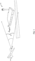
- FIG. 1 shows an example scenario in which an aircraft 100 scans an airport environment 102 with a LiDAR device 104 to acquire LiDAR data for the airport environment 102.
- the LiDAR device 104 includes an emitter configured to emit numerous pulses of laser light toward the airport environment 102, such as representative pulses 106.
- the pulses emitted by the LiDAR device 104 reflect off of surfaces in the airport environment 102 and are received by a sensor of the LiDAR device 104. Each pulse generates an individual point representative of a part of the airport environment 102.
- the LiDAR device 104 aggregates these points to form a LiDAR point cloud 200 (shown in FIG. 2 ) that collectively represents the airport environment 102.
- the number of pulses emitted / received by the LiDAR device 104 to generate a LiDAR point cloud can vary, in accordance with the particular application and without undue experimentation, from that which is shown in FIG. 1 .
- a LiDAR point cloud of an airport environment can include a range of 2-10 or more points per square meter of the airport environment.
- the aircraft 100 may perform a plurality of LiDAR scans of the airport environment 102 from different positions to aggregate points to contribute to the LiDAR point cloud 200 (shown in FIG. 2 ) throughout different phases of a mission.
- the aircraft 100 can scan the airport environment 102 with the LiDAR device 104 during taxi, takeoff, approach, and/or landing, depending on the mission.
- Different vehicles outfitted with LiDAR devices may perform scans of the airport environment 102 during a designated time window to collect LiDAR data (e.g., points in the LiDAR point cloud 200 shown in FIG. 2 ).
- the LiDAR scans may be performed within the designated time window in order to increase the likelihood that dynamic objects (e.g., vehicles) in the airport environment 102 remain in the same position to be captured in the LiDAR point cloud.
- Different aircraft may perform LiDAR scans throughout different phases of their respective missions to collect LiDAR data.
- Different ground vehicles e.g., tractor vehicles, stairway vehicles, belt loader vehicles
- Fixed LiDAR devices may be positioned around the airport environment 102 to collect LiDAR data.
- LiDAR data generated from a plurality of LiDAR scans from different LiDAR devices can be aggregated to form the LiDAR point cloud 200 (shown in FIG. 2 ).
- the LiDAR point cloud 200 (shown in FIG. 2 ) may be generated in any suitable manner.
- FIG. 2 shows the LiDAR point cloud 200 of the airport environment 102 of FIG. 1 .
- the LiDAR point cloud 200 typically includes a very large collection of individual points plotted in three-dimensional (3D) space.
- Each point, such as point 202, included in the LiDAR point cloud 200 includes Cartesian coordinates (X, Y, and Z) and an intensity value (i).
- the intensity value (i) represents the recorded return strength of a laser beam. In one example, the intensity value (i) can be between 1-256.
- the intensity value (i) varies with the composition of the surface object reflecting the laser beam. For example, a low number may indicate low reflectivity while a high number indicates high reflectivity.
- the scale of the intensity value (i) can depend on the LiDAR sensor that is taking the measurements. In one example, the intensity scale includes decimal values between [0, 1]. In another example, the intensity scale includes values between [0, 255].
- the intensity of the laser beam return can also be affected by the angle of arrival (scan angle), range, surface composition, roughness, and moisture content in the atmosphere when the LiDAR scan is performed. This means that features under the nadir of the LiDAR device usually have higher intensity than the same features along the edges (tilted further), as the returned energy decreases.
- the intensity values of the LiDAR point cloud 200 may be used for various analysis of the LiDAR point cloud 200. For example, analysis of the intensity values may be performed for data registration, feature extraction, classification, surface analysis, and segmentation, among other types of analysis.
- FIG. 3 schematically shows an example computing system 300 configured to execute a processing pipeline 301 that is configured to automatically annotate a LiDAR point cloud, such as the LiDAR point cloud 200 shown in FIG. 2 .
- the processing pipeline 301 is configured to receive LiDAR data 302.
- the LiDAR data 302 can be received from one or more LiDAR devices that perform one or more LiDAR scans of an airport environment, such as the airport environment 102 shown in FIG. 1 .
- a LiDAR scan can include emitting laser light pulses via an emitter of a LiDAR device into an airport environment and receiving reflected pulses that are reflected off of airport-related objects in the airport environment via a sensor of the LiDAR device.
- the LiDAR data 302 is received from a single LiDAR device.
- the LiDAR device is an aircraft-mounted LiDAR device.
- the LiDAR data 302 is accumulated from a plurality of LiDAR scans performed by the LiDAR device.
- the LiDAR data 302 is received from a plurality of LiDAR devices.
- the plurality of LiDAR devices are mounted to different vehicles in the airport environment, such as aircraft and ground vehicles.
- at least some of the LiDAR data 302 is received from one or more fixed LiDAR devices positioned within the airport environment.
- the LiDAR data 302 is accumulated from a plurality of LiDAR scans performed by a plurality of LiDAR devices.
- the LiDAR data 302 is aggregated by the processing pipeline 301 to form a LiDAR point cloud 304.
- the LiDAR point cloud 304 includes a plurality of points in the airport environment. More particularly, each point included in the LiDAR point cloud 304 includes X, Y, and Z coordinates and an intensity value (i) representing a reflectivity of a surface in the airport environment.
- the processing pipeline 301 includes segmentation logic 306.
- the segmentation logic 306 is configured to receive the LiDAR point cloud 304 and output a segmented LiDAR point cloud 308 including a ground region 310 and a non-ground region 312.
- the ground region 310 includes points corresponding to the ground surface in the airport environment.
- the ground region 310 can include various surface level airport-related objects or features, such as runways, roads, sidewalks, fields, water, etc.
- the non-ground region 312 includes points corresponding to objects or features above or extending above ground level, such as vehicles, terminals, hangars, air traffic control towers, etc.
- the segmentation logic 306 may be configured to segment the LiDAR point cloud 304 using any suitable segmentation algorithm or technique. In one example, the segmentation logic 306 segments the LiDAR point cloud 304 using a plane fitting algorithm.
- the processing pipeline 301 includes a trained machine learning model 314 that is configured to receive the segmented LiDAR point cloud 308 as input. Additionally, the trained machine learning model 314 is configured to receive an airport domain 316 as input.
- the airport domain 316 includes a library of classification labels 318 that are specific to airport environments.
- the library of classification labels 318 includes different types of classification labels including dynamic semantic labels 320 for movable objects (e.g., aircraft, ground vehicles) and non-dynamic semantic labels 322 for fixed objects (e.g., terminals, hangars, air traffic control towers). Note that such classification labels denote objects as being dynamic or non-dynamic. Further, the classification labels denote particular airport-related classes of objects (e.g., aircraft, ground vehicles, terminals, hangars, air traffic control towers).
- the trained machine learning model 314 leverages the airport domain 316 to perform automatic clustering and annotation operations that are specialized for airport environments.
- the trained machine learning model 314 is configured to automatically cluster different points in the non-ground region 312 into a plurality of non-ground segments 324 (e.g., 1, 2, N).
- the trained machine learning model 314 typically does not perform clustering of points in the ground region 310 in order to reduce consumption of resources and reduce the time it takes to perform the clustering operations.
- the non-ground segments 324 represent airport-related objects that are typically found in airport environments.
- the airport domain 316 informs the trained machine learning model 314 about features of airport-related objects that the trained machine learning model 314 can then recognize and use for making clustering decisions for the non-ground segments 324.
- the trained machine learning model 314 is configured to automatically annotate the plurality of non-ground segments 324 with classification labels 326 selected from the library of classification labels 318 of the airport domain 316.
- a non-ground segment 324 corresponding to a moveable object may be labeled with a dynamic semantic label 320.
- a non-ground segment 324 corresponding to a fixed object may be labeled with a non-dynamic semantic label 322.
- the trained machine learning model 314 is configured to automatically annotate the plurality of non-ground segments 324 with one or more classification labels 326 and one or more confidences corresponding to the one or more classification labels.
- a confidence indicates a level of correlation between the non-ground segment and the particular classification label. For example, a higher confidence indicates a stronger correlation with a particular classification label and vice versa. For example, a confidence greater than 90% may indicate a strong correlation that the non-ground segment is, in fact, the particular type of classification. Note that confidences may be assessed based on any suitable threshold. In one example, a non-ground segment might be classified as an aircraft with 95% confidence and a refueling truck with 5% confidence.
- the non-ground segment has a strong correlation to the aircraft and a weak correlation to the refueling truck.
- a non-ground segment may be labeled with a plurality of classification labels based at least on a highest determined confidence corresponding to a classification label being below a threshold.
- the trained machine learning model 314 may be configured to automatically annotate the plurality of non-ground segments 324 with any suitable number of classification labels and corresponding confidences.
- the trained machine learning model 314 is configured to output a panoptic labeled LiDAR point cloud 328 including the plurality of non-ground segments 324 labeled with respective classification labels 326 and the points in the ground region 310.
- the points in the ground region 310 are added back into the panoptic labeled LiDAR point cloud 328, so that it provides a comprehensive representation of the entire airport environment, including airport-related objects that are accurately identified and classified as non-ground segments 324.
- the trained machine learning model 314 is configured to generate a plurality of masks 332 corresponding to the plurality of non-ground segments 324.
- each mask 332 forms solid surfaces of a non-ground segment (e.g., an airport-related object) that collectively produce a solid representation of the non-ground segment.
- the trained machine learning model 314 may be configured to texture map the plurality of masks 332 onto the plurality of non-ground segments 324 in the panoptic labeled LiDAR point cloud 328 to make it easier to visually recognize the objects in the panoptic labeled LiDAR point cloud 328.
- the trained machine learning model 314 is configured to annotate the plurality of non-ground segments 324 with individualized identifiers 330.
- positions of the plurality of non-ground segments 324 can be tracked via respective individualized identifiers 330 across a plurality of panoptic labeled LiDAR point clouds output by the processing pipeline 301 over a designated time period.
- Such position tracking may allow for the behavior or tendencies of dynamic non-ground segments to be learned and applied to re-training of the trained machine learning model 314 to improve classification accuracy and/or to learn additional functionality.
- the mask generation functionality and/or the individualized identifier annotation functionality may be performed by other logic in the processing pipeline 301 instead of the trained machine learning model 314.
- the trained machine learning model 314 may take various forms.
- the trained machine learning model 314 is a neural network.
- the neural network is a convolutional neural network.
- the convolutional neural network is a dynamic graph convolutional neural network.
- the neural network is a fully connected neural network.
- the neural network is a one-stage type of neural network, such as a single shot detection neural network.
- the neural network is a two-stage type of neural network, such as a feature pyramid neural network or a region proposal neural network.
- the trained machine learning model 314 may be any suitable type of neural network that is trained to classify non-ground segments with airport-based classification labels using any suitable object detection and/or localization techniques.
- the processing pipeline 301 includes labeling logic 334 that is configured to receive one or more images 336 of the airport environment captured by one or more cameras.
- an aircraft equipped with a LiDAR device may also be equipped with an RGB camera, an infrared camera, a night vision camera, and/or another type of camera that outputs images of the airport environment.
- the labeling logic 334 is configured to receive the panoptic labeled LiDAR point cloud 328.
- the labeling logic 334 is configured to automatically annotate a plurality of objects in the one or more images 336 with classification labels 326 corresponding to the plurality of non-ground segments 324 in the panoptic labeled LiDAR point cloud 328.
- the classification information in the panoptic labeled LiDAR point cloud 328 can be leveraged to automatically label the image(s) in a faster and more accurate manner than human annotation of a LiDAR point cloud without any human involvement.
- Such labeled images may be beneficially used for various applications, such as input for navigation systems of automated aircraft or training data for training machine learning models to automatically label images of airport environments.
- the panoptic labeled LiDAR point cloud 328 is included in a set of training data 340.
- the computing system 300 includes a model trainer 342 that is configured to re-train the trained machine learning model 314 based at least on the set of training data 340.
- the set of training data 340 may include a plurality of panoptic labeled LiDAR point clouds 328 generated over a designated time period.
- Such re-training of the trained machine learning model 314 allows for the trained machine learning model 314 to self-learn relevant features directly from the panoptic labeled LiDAR point clouds 328 to improve clustering and classification accuracy with each re-training cycle and without the need for human involvement in the annotation process.
- the model trainer 342 can re-train the trained machine learning model 314 based at least on any suitable number of panoptic labeled LiDAR point clouds 328.
- the model trainer 342 can re-train the trained machine learning model 314 according to any suitable frequency in any suitable manner. In some examples, the frequency at which the model is re-trained depends on the residual error of the model, and re-training is performed when new data is processed and new/corner cases are discovered.
- FIG. 4 schematically shows an example process flow 400 according to which the processing pipeline 301 shown in FIG. 3 generates a panoptic labeled LiDAR point cloud 328.
- a LiDAR point cloud is received as input.
- the LiDAR point cloud is segmented, via the segmentation logic 306, into a ground region 406 of points corresponding to the ground and to a non-ground region 408 of points corresponding to points above the ground.
- points in the non-ground region 408 are clustered into non-ground segments via the trained machine learning model 314.
- non-ground segments are annotated with classification labels selected from the airport domain via the trained machine learning model 314.
- a panoptic labeled LiDAR point cloud 328 is output.
- the panoptic labeled LiDAR point cloud 328 includes the plurality of non-ground segments labeled with respective classification labels and the points in the ground region.
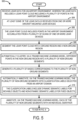
- FIGS. 5-6 show a flowchart of an example computer-implemented method 500 for automatically annotating a LiDAR point cloud with classification labels to generate a panoptic labeled LiDAR point cloud.
- the computer-implemented method 500 may be performed by the computing system 300 shown in FIG. 3 or another computing system.
- the computer-implemented method 500 includes receiving LiDAR data for an airport environment.
- the LiDAR data includes a LiDAR point cloud including a plurality of points in the airport environment.
- Each point included in the LiDAR point cloud includes X, Y, and Z coordinates and an intensity value (i).
- At 504 at least some of the LiDAR data can be received from an aircraft-mounted LiDAR device, such as the LiDAR device 104 mounted to the aircraft 100 shown in FIG. 1 .
- the LiDAR point cloud may include points in the airport environment accumulated from a plurality of scans of one or more LiDAR devices.
- the plurality of scans may be performed by the same LiDAR device, such as an aircraft-mounted LiDAR device.
- the plurality of scans be performed by different LiDAR devices, such as different vehicle-mounted LiDAR devices.
- the computer-implemented method 500 includes segmenting the LiDAR point cloud into a ground region and a non-ground region. Any suitable segmentation technique may be used to segment the LiDAR point cloud.
- the LiDAR point cloud is segmented by employing a plane fitting segmentation technique that is applied to points aligned with the ground in the airport environment.
- the computer-implemented method 500 includes automatically clustering, via a trained machine learning model, different points in the non-ground region into a plurality of non-ground segments.
- the non-ground segments may correspond to different objects in the airport environment, such as buildings, vehicles, trees, and other objects.
- the trained machine learning model may be trained on a set of training data including LiDAR point clouds of airport environments including different airport related objects (e.g., aircraft, ground vehicles, terminals, traffic control towers, runways) at different positions within the LiDAR point clouds.
- the computer-implemented method 500 may include generating a plurality of masks corresponding to the plurality of non-ground segments. Each of the plurality of masks connects groups of points in the non-ground segments to form surfaces in order to visualize identified objects more easily in the LiDAR point cloud.
- the computer-implemented method 500 includes automatically annotating, via the trained machine learning model, the plurality of non-ground segments with classification labels selected from an airport domain.
- the airport domain includes a library of classification labels corresponding to airport-related objects.
- the classification labels include dynamic semantic labels for movable objects and non-dynamic semantic labels for fixed objects. Note that these semantic classification labels identify an object as being dynamic or non-dynamic, and in addition, identifying the object as being part of a more granular airport-related class, such as an aircraft, ground vehicle, terminal, traffic control tower, runway, or another class of airport-related object.
- the computer-implemented method 500 may include annotating, via the trained machine learning model, each of the plurality of non-ground segments with an individualized identifier.
- individualized identifiers enable positions of the plurality of non-ground segments (e.g., dynamic airport-related objects, such as aircraft or ground vehicles) to be tracked across a plurality of panoptic labeled LiDAR point clouds generated for a designated time period.
- the computer-implemented method 500 includes outputting a panoptic labeled LiDAR point cloud including the plurality of non-ground segments labeled with respective classification labels and the points in the ground region.
- the panoptic labeled LiDAR point cloud provides a comprehensive representation of the airport environment including airport-related objects that are accurately identified and classified.
- the panoptic labeled LiDAR point cloud includes non-ground segments annotated with the individualized identifiers.
- the individualized identifiers allow for the non-ground segments to be tracked across a plurality of panoptic labeled LiDAR point clouds generated for a designated time period.
- the panoptic labeled LiDAR point cloud includes the plurality of masks aligned with the non-ground segments.
- the plurality of masks form surfaces of airport-related objects that allow for the airport-related objects to be recognized more easily.
- the computer-implemented method 500 may include receiving one or more images of the airport environment captured by one or more cameras.
- an aircraft equipped with a LiDAR device may also be equipped with an RGB camera, an infrared camera, a night vision camera, and/or another type of camera that outputs images of the airport environment.
- the computer-implemented method 500 may include automatically annotating a plurality of objects in the one or more images with classification labels corresponding to the plurality of non-ground segments in the panoptic labeled LiDAR point cloud.
- the classification information in the panoptic labeled LiDAR point cloud can be leveraged to automatically label the image(s) in a faster and more accurate manner than human annotation of a LiDAR point cloud without any human involvement.
- Such labeled images may be beneficially used for various applications, such as input for navigation systems of automated aircraft or training data for training machine learning models to automatically label images of airport environments.
- the computer-implemented method 500 may include re-training the trained machine learning model based at least on a set of training data including the panoptic labeled LiDAR point cloud.
- the set of training data may include a plurality of panoptic labeled LiDAR point clouds generated over a designated time period.
- Such re-training of the trained machine learning model allows for the trained machine learning model to self-learn relevant features (e.g., aircraft, ground vehicles, terminals, hangars, air traffic control towers, and other airport-related objects) directly from the panoptic labeled LiDAR point clouds to improve clustering and classification accuracy with each re-training cycle and without the need for human involvement in the annotation process.
- the above systems and methods may be employed to perform unsupervised segmentation, clustering, and annotation of points in a LiDAR point cloud using a trained machine learning model that produces a panoptic labeled LiDAR point cloud faster and having higher classification accuracy relative to a LiDAR point cloud that is annotated by a human.
- the methods and processes described herein may be tied to a computing system of one or more computing devices.
- such methods and processes may be implemented as a computer-application program or service, an application-programming interface (API), a library, and/or other computer-program product.
- API application-programming interface
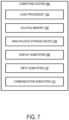
- FIG. 7 schematically shows an example implementation of a computing system 700 that can enact one or more of the methods and processes described above.
- Computing system 700 may embody the computing system 300 shown in FIG. 3 .
- Computing system 700 may take the form of one or more personal computers, server computers, tablet computers, network computing devices, mobile computing devices, mobile communication devices (e.g., smart phones), wearable computing devices such as smart wristwatches and head mounted augmented reality devices, embedded computing devices, Internet of Things (IoT) computing devices, and/or other computing devices.
- Computing system 700 includes a logic processor 702, volatile memory 704, and a non-volatile storage device 706.
- Computing system 700 may optionally include a display subsystem 708, input subsystem 710, communication subsystem 712, and/or other components not shown in FIG. 7 .
- Logic processor 702 includes one or more physical devices configured to execute instructions.
- the logic processor may be configured to execute instructions that are part of one or more applications, programs, routines, libraries, objects, components, data structures, or other logical constructs. Such instructions may be implemented to perform a task, implement a data type, transform the state of one or more components, achieve a technical effect, and/or otherwise arrive at a desired result.
- the logic processor may include one or more physical processors (e.g., hardware) configured to execute software instructions. Additionally or alternatively, the logic processor may include one or more hardware logic circuits or firmware devices configured to execute hardware-implemented logic or firmware instructions. Processors of the logic processor 702 may be single-core or multi-core, and the instructions executed thereon may be configured for sequential, parallel, and/or distributed processing. Individual components of the logic processor optionally may be distributed among two or more separate devices, which may be remotely located and/or configured for coordinated processing. Aspects of the logic processor may be virtualized and executed by remotely accessible, networked computing devices configured in a cloud-computing configuration.
- Non-volatile storage device 706 includes one or more physical devices configured to hold instructions executable by the logic processors to implement the methods and processes described herein. When such methods and processes are implemented, the state of non-volatile storage device 706 may be transformed-e.g., to hold different data.
- Non-volatile storage device 706 may include physical devices that are removable and/or built-in.
- Non-volatile storage device 706 may include optical memory (e.g., CD, DVD, HD-DVD, Blu-Ray Disc), semiconductor memory (e.g., ROM, EPROM, EEPROM, FLASH memory), and/or magnetic memory (e.g., hard-disk drive, floppy-disk drive, tape drive, MRAM), and/or other mass storage device technology.
- Non-volatile storage device 706 may include nonvolatile, dynamic, static, read/write, read-only, sequential-access, location-addressable, file-addressable, and/or content-addressable devices.
- non-volatile storage device 706 is configured to hold instructions even if the supply of power to the non-volatile storage device 706 is interrupted or discontinued.
- Volatile memory 704 may include physical devices that include random access memory (RAM).
- RAM random access memory
- Volatile memory 704 is typically utilized by logic processor 702 to temporarily store information during processing of software instructions. It will be appreciated by those of ordinary skill in the art without undue experimentation that volatile memory 704 typically does not continue to store instructions if the supply of power to the volatile memory 704 is interrupted or discontinued.
- logic processor 702, volatile memory 704, and non-volatile storage device 706 may be integrated together into one or more hardware-logic components.
- Such hardware-logic components may include field-programmable gate arrays (FPGAs), program- and application-specific integrated circuits (PASIC / ASICs), program- and application-specific standard products (PSSP / ASSPs), system-on-a-chip (SOC), and/or complex programmable logic devices (CPLDs), for example.
- FPGAs field-programmable gate arrays
- PASIC / ASICs program- and application-specific integrated circuits
- PSSP / ASSPs program- and application-specific standard products
- SOC system-on-a-chip
- CPLDs complex programmable logic devices
- module may describe an aspect of computing system 700 typically implemented in software by a processor to perform a particular function using portions of volatile memory, which function involves transformative processing that specially configures the processor to perform the function.
- a module, program, or engine may be instantiated via logic processor 702 executing instructions held by non-volatile storage device 706, using portions of volatile memory 704. It will be understood by those of ordinary skill in the art without undue experimentation that different modules, programs, and/or engines may be instantiated from the same application, service, code block, object, library, routine, API, function, etc.
- module may be instantiated by different applications, services, code blocks, objects, routines, APIs, functions, etc.
- the terms “module,” “program,” and “engine,” as used herein, may encompass individual or groups of executable files, data files, libraries, drivers, scripts, database records, etc.
- display subsystem 708 may be used to present a visual representation of data held by non-volatile storage device 706.
- the visual representation may take the form of a graphical user interface (GUI).
- GUI graphical user interface
- the state of display subsystem 708 may likewise be transformed to visually represent changes in the underlying data.
- Display subsystem 708 may include one or more display devices utilizing virtually any type of technology. Such display devices may be combined with logic processor 702, volatile memory 704, and/or non-volatile storage device 706 in a shared enclosure, or such display devices may be peripheral display devices.
- input subsystem 710 may comprise or interface with one or more user-input devices such as a keyboard, mouse, touch screen, or game controller.
- the input subsystem may comprise or interface with selected natural user input (NUI) componentry.
- NUI natural user input
- Such componentry may be integrated or peripheral, and the transduction and/or processing of input actions may be handled on- or off-board.
- NUI componentry may include a microphone for speech and/or voice recognition; an infrared, color, stereoscopic, and/or depth camera for machine vision and/or gesture recognition; a head tracker, eye tracker, accelerometer, and/or gyroscope for motion detection and/or intent recognition; as well as electric-field sensing componentry for assessing brain activity; and/or any other suitable sensor.
- communication subsystem 712 may be configured to communicatively couple various computing devices described herein with each other, and/or with other devices.
- Communication subsystem 712 may include wired and/or wireless communication devices compatible with one or more different communication protocols.
- the communication subsystem may be configured for communication via a wireless telephone network, or a wired or wireless local- or wide-area network, such as a HDMI over Wi-Fi connection.
- the communication subsystem may allow computing system 700 to send and/or receive messages to and/or from other devices via a network such as the Internet.
- a computing device comprises one or more processors configured to execute instructions stored in memory to receive laser imaging detection and ranging (LiDAR) data for an airport environment, wherein the LiDAR data includes a LiDAR point cloud including a plurality of points in the airport environment, segment the LiDAR point cloud into a ground region and a non-ground region, automatically cluster, via a trained machine learning model, different points in the non-ground region into a plurality of non-ground segments, automatically annotate, via the trained machine learning model, the plurality of non-ground segments with classification labels selected from an airport domain, and output a labeled LiDAR point cloud including the plurality of non-ground segments labeled with respective classification labels and the points in the ground region.
- LiDAR laser imaging detection and ranging
- the LiDAR point cloud may include points in the airport environment accumulated from a plurality of scans of one or more LiDAR devices.
- at least some of the LiDAR data may be received from one or more aircraft-mounted LiDAR devices.
- the airport domain may include a library of classification labels corresponding to airport-related objects.
- each point included in the LiDAR point cloud may include X, Y, and Z coordinates and an intensity value.
- the classification labels may include dynamic semantic labels for movable objects and non-dynamic semantic labels for fixed objects.
- the one or more processors may be configured to execute instructions stored in memory to generate a plurality of masks corresponding to the plurality of non-ground segments, and wherein the labeled LiDAR point cloud includes the plurality of masks.
- the one or more processors may be configured to annotate each of the plurality of non-ground segments with an individualized identifier.
- the one or more processors may be configured to execute instructions stored in memory to receive one or more images of the airport environment captured by one or more cameras, and automatically annotate a plurality of objects in the one or more images with classification labels corresponding to the plurality of non-ground segments in the labeled LiDAR point cloud.
- the labeled LiDAR point cloud may be included in a set of training data
- the one or more processors may be configured to execute instructions stored in memory to re-train the trained machine learning model based at least on the set of training data.
- a computer-implemented method comprises receiving LiDAR data for an airport environment, wherein the LiDAR data includes a LiDAR point cloud including a plurality of points in the airport environment, segmenting the LiDAR point cloud into a ground region and a non-ground region, automatically clustering, via a trained machine learning model, different points in the non-ground region into a plurality of non-ground segments, automatically labeling, via the trained machine learning model, the plurality of non-ground segments with classification labels selected from an airport domain, and outputting a labeled LiDAR point cloud including the plurality of non-ground segments labeled with respective classification labels and the points in the ground region.
- the computer-implemented method may further comprise generating a plurality of masks corresponding to the plurality of non-ground segments, and wherein the labeled LiDAR point cloud includes the plurality of masks.
- the computer-implemented method may further comprise annotating via the trained machine learning model, each of the plurality of non-ground segments with an individualized identifier.
- the computer-implemented method may further comprise receiving one or more images of the airport environment captured by one or more cameras, and automatically annotating a plurality of objects in the one or more images with classification labels corresponding to the plurality of non-ground segments in the labeled LiDAR point cloud.
- the labeled LiDAR point cloud may be included in a set of training data, and the computer-implemented method may further comprise re-training the trained machine learning model based at least on the set of training data.
- the LiDAR point cloud may include points in the airport environment accumulated from a plurality of scans of one or more LiDAR devices.
- at least some of the LiDAR data may be received from one or more aircraft-mounted LiDAR devices.
- the airport domain may include a library of classification labels corresponding to airport-related objects.
- the classification labels may include dynamic semantic labels for movable objects and non-dynamic semantic labels for fixed objects.
- a computing device comprises one or more processors configured to execute instructions stored in memory to receive LiDAR data for an airport environment, wherein the LiDAR data includes a LiDAR point cloud including a plurality of points in the airport environment, segment the LiDAR point cloud into a ground region and a non-ground region, automatically cluster, via a trained machine learning model, different points in the non-ground region into a plurality of non-ground segments, automatically annotate, via the trained machine learning model, the plurality of non-ground segments with classification labels selected from an airport domain, output a labeled LiDAR point cloud including the plurality of non-ground segments labeled with respective classification labels and the points in the ground region, wherein the labeled LiDAR point cloud is in a set of training data, and re-train the trained machine learning model based at least on the set of training data including the labeled LiDAR point cloud.
Landscapes
- Engineering & Computer Science (AREA)
- Physics & Mathematics (AREA)
- General Physics & Mathematics (AREA)
- Remote Sensing (AREA)
- Theoretical Computer Science (AREA)
- Radar, Positioning & Navigation (AREA)
- Computer Networks & Wireless Communication (AREA)
- Multimedia (AREA)
- Electromagnetism (AREA)
- Evolutionary Computation (AREA)
- Software Systems (AREA)
- Databases & Information Systems (AREA)
- General Health & Medical Sciences (AREA)
- Medical Informatics (AREA)
- Computing Systems (AREA)
- Computer Vision & Pattern Recognition (AREA)
- Artificial Intelligence (AREA)
- Health & Medical Sciences (AREA)
- Computational Linguistics (AREA)
- Aviation & Aerospace Engineering (AREA)
- Image Analysis (AREA)
- Optical Radar Systems And Details Thereof (AREA)
- Traffic Control Systems (AREA)
Abstract
Description
- The present disclosure relates generally to the field of light detection and ranging (LiDAR), and more specifically to annotating a LiDAR point cloud with classification labels.
- Light detection and ranging (LiDAR) uses laser light to measure distances by targeting an object or a surface with a laser and measuring the time for the reflected light to return to a receiver. LiDAR scanning can be performed to generate extremely accurate, detailed three-dimensional (3D) measurements of an environment including various features, such as the ground, vegetation, buildings, and other objects. LiDAR scanning produces a 3D point cloud of the scanned environment. The speed and accuracy of LiDAR made it feasible to map large areas with the kind of detail that before had only been possible with time-consuming and expensive ground survey crews.
- LiDAR point clouds are commonly used to generate labeled maps of airport environments. Annotation of a LiDAR point cloud with classification labels is traditionally performed by humans. However, such human annotation of LiDAR point clouds representing airport environments can have issues. As one example, a human annotator, even if experienced, can create labeling errors that produce a mislabeled LiDAR point cloud that misrepresents an airport environment. As another example, the time it takes for a human annotator to annotate a LiDAR point cloud of an airport environment can be substantial to the point that the resulting human-annotated LiDAR point cloud of the airport environment can be rendered obsolete by the time it is finished. More particularly, dynamic objects may change position during the time it takes for the human annotator to produce the human-annotated LiDAR point cloud, such that it does not accurately represent the current state of the airport environment.
- Examples are disclosed that relate an approach for automatically annotating a light detection and ranging (LiDAR) point cloud of an airport with classification labels in a faster and more accurate manner than human annotation of a LiDAR point cloud. In one example, a computing device comprises one or more processors configured to execute instructions stored in memory to (1) receive LiDAR data for an airport environment, wherein the LiDAR data includes a LiDAR point cloud including a plurality of points in the airport environment, (2) segment the LiDAR point cloud into a ground region and a non-ground region, (3) automatically cluster, via a trained machine learning model, different points in the non-ground region into a plurality of non-ground segments, (4) automatically annotate, via the trained machine learning model, the plurality of non-ground segments with classification labels selected from an airport domain, and (5) output a panoptic labeled LiDAR point cloud including the plurality of non-ground segments labeled with respective classification labels and the points in the ground region.
- The features, functions, and advantages that have been discussed can be achieved independently in various embodiments or may be combined in yet other embodiments further details of which can be seen with reference to the following description and drawings.
-
-
FIG. 1 shows an example scenario in which an aircraft scans an airport environment with a light detection and ranging (LiDAR) device to acquire LiDAR data for the airport environment. -
FIG. 2 shows an example LiDAR point cloud of the airport environment ofFIG. 1 . -
FIG. 3 schematically shows an example computing system configured to automatically annotate a LiDAR point cloud with classification labels to generate a panoptic labeled LiDAR point cloud. -
FIG. 4 schematically shows an example process flow for generating a panoptic labeled LiDAR point cloud. -
FIGS. 5-6 show a flowchart of an example computer-implemented method for automatically annotating a LiDAR point cloud with classification labels to generate a panoptic labeled LiDAR point cloud. -
FIG. 7 schematically shows an example computing system that may embody the computing system ofFIG. 3 . - The present description is directed to a computer-implemented approach for automatically annotating a light detection and ranging (LiDAR) point cloud of an airport with classification labels in a faster and more accurate manner than human annotation of a LiDAR point cloud. In one example, LiDAR data for an airport environment is received, the LiDAR data including a LiDAR point cloud with a plurality of points representing the airport environment. The LiDAR point cloud is segmented into a ground region and a non-ground region. Different points in the non-ground region are automatically clustered, via a trained machine learning model, into a plurality of non-ground segments. The plurality of non-ground segments are automatically annotated, via the trained machine learning model, with classification labels selected from an airport domain. A panoptic labeled LiDAR point cloud is output. The panoptic labeled LiDAR point cloud includes the plurality of non-ground segments labeled with respective classification labels and the points in the ground region.
- The computer-implemented approach performs unsupervised panoptic segmentation of a LiDAR point cloud of an airport environment using auto-learning/self-learning techniques that enable automatic annotation of the LiDAR point cloud with classification labels without human involvement. The computer-implemented approach intelligently segments the LiDAR point cloud into ground and non-ground regions to reduce an overall number of points that need to be analyzed by the trained machine learning model, to reduce time and processing resources needed to generate the panoptic labeled LiDAR point cloud.
- The trained machine learning model is trained using airport-specific domain knowledge that enables the trained machine learning model to automatically cluster points in the non-ground region into segments that correspond to objects typically found in an airport environment without human involvement. Training the machine learning model based on airport-specific domain knowledge enables the trained machine learning model to identify airport-specific objects in the LiDAR point cloud with increased accuracy relative to a human annotator or a generically trained machine learning model. Moreover, the trained machine learning model leverages the airport-specific domain knowledge to automatically annotate the non-ground segments with airport-specific classification labels (e.g., aircraft, truck, terminal, skybridge, tower) that provide a higher granularity of classification relative to more generic labels (e.g., dynamic object, non-dynamic object labels).
- In some implementations, panoptic labeled LiDAR point clouds generated using the computer-implemented approach can be used by a navigation system of an autonomous aircraft. Moreover, particularly, the computer-implemented approach can produce the panoptic labeled LiDAR point clouds suitably fast enough that the information embedded within the panoptic labeled LiDAR point clouds is still accurate enough for the navigation system to operate the autonomous aircraft based on such information.
FIG. 1 shows an example scenario in which anaircraft 100 scans anairport environment 102 with a LiDAR device 104 to acquire LiDAR data for theairport environment 102. In particular, the LiDAR device 104 includes an emitter configured to emit numerous pulses of laser light toward theairport environment 102, such asrepresentative pulses 106. The pulses emitted by the LiDAR device 104 reflect off of surfaces in theairport environment 102 and are received by a sensor of the LiDAR device 104. Each pulse generates an individual point representative of a part of theairport environment 102. The LiDAR device 104 aggregates these points to form a LiDAR point cloud 200 (shown inFIG. 2 ) that collectively represents theairport environment 102. The number of pulses emitted / received by the LiDAR device 104 to generate a LiDAR point cloud can vary, in accordance with the particular application and without undue experimentation, from that which is shown inFIG. 1 . As one example, a LiDAR point cloud of an airport environment can include a range of 2-10 or more points per square meter of the airport environment. - The
aircraft 100 may perform a plurality of LiDAR scans of theairport environment 102 from different positions to aggregate points to contribute to the LiDAR point cloud 200 (shown inFIG. 2 ) throughout different phases of a mission. For example, theaircraft 100 can scan theairport environment 102 with the LiDAR device 104 during taxi, takeoff, approach, and/or landing, depending on the mission. - By performing a plurality of LiDAR scans from different positions, different parts of the
airport environment 102 can be exposed to the LiDAR device 104 at different positions and captured in the LiDAR point cloud 200 (shown inFIG. 2 ) to get a panoptic representation of theairport environment 102. Different vehicles outfitted with LiDAR devices may perform scans of theairport environment 102 during a designated time window to collect LiDAR data (e.g., points in the LiDARpoint cloud 200 shown inFIG. 2 ). The LiDAR scans may be performed within the designated time window in order to increase the likelihood that dynamic objects (e.g., vehicles) in theairport environment 102 remain in the same position to be captured in the LiDAR point cloud. Different aircraft may perform LiDAR scans throughout different phases of their respective missions to collect LiDAR data. Different ground vehicles (e.g., tractor vehicles, stairway vehicles, belt loader vehicles) may perform LiDAR scans to collect LiDAR data. Fixed LiDAR devices may be positioned around theairport environment 102 to collect LiDAR data. LiDAR data generated from a plurality of LiDAR scans from different LiDAR devices (attached to vehicles or fixed) can be aggregated to form the LiDAR point cloud 200 (shown inFIG. 2 ). The LiDAR point cloud 200 (shown inFIG. 2 ) may be generated in any suitable manner. -
FIG. 2 shows the LiDARpoint cloud 200 of theairport environment 102 ofFIG. 1 . Although not specifically depicted inFIG. 2 , it is understood by those of ordinary skill in the art that the LiDARpoint cloud 200 typically includes a very large collection of individual points plotted in three-dimensional (3D) space. Each point, such aspoint 202, included in the LiDARpoint cloud 200 includes Cartesian coordinates (X, Y, and Z) and an intensity value (i). The intensity value (i) represents the recorded return strength of a laser beam. In one example, the intensity value (i) can be between 1-256. - The intensity value (i) varies with the composition of the surface object reflecting the laser beam. For example, a low number may indicate low reflectivity while a high number indicates high reflectivity. The scale of the intensity value (i) can depend on the LiDAR sensor that is taking the measurements. In one example, the intensity scale includes decimal values between [0, 1]. In another example, the intensity scale includes values between [0, 255]. The intensity of the laser beam return can also be affected by the angle of arrival (scan angle), range, surface composition, roughness, and moisture content in the atmosphere when the LiDAR scan is performed. This means that features under the nadir of the LiDAR device usually have higher intensity than the same features along the edges (tilted further), as the returned energy decreases. The intensity values of the
LiDAR point cloud 200 may be used for various analysis of theLiDAR point cloud 200. For example, analysis of the intensity values may be performed for data registration, feature extraction, classification, surface analysis, and segmentation, among other types of analysis. -
FIG. 3 schematically shows anexample computing system 300 configured to execute aprocessing pipeline 301 that is configured to automatically annotate a LiDAR point cloud, such as theLiDAR point cloud 200 shown inFIG. 2 . Theprocessing pipeline 301 is configured to receiveLiDAR data 302. TheLiDAR data 302 can be received from one or more LiDAR devices that perform one or more LiDAR scans of an airport environment, such as theairport environment 102 shown inFIG. 1 . Note that a LiDAR scan can include emitting laser light pulses via an emitter of a LiDAR device into an airport environment and receiving reflected pulses that are reflected off of airport-related objects in the airport environment via a sensor of the LiDAR device. - In some examples, the
LiDAR data 302 is received from a single LiDAR device. In some examples, the LiDAR device is an aircraft-mounted LiDAR device. In some examples, theLiDAR data 302 is accumulated from a plurality of LiDAR scans performed by the LiDAR device. In other examples, theLiDAR data 302 is received from a plurality of LiDAR devices. In some examples, the plurality of LiDAR devices are mounted to different vehicles in the airport environment, such as aircraft and ground vehicles. In some examples, at least some of theLiDAR data 302 is received from one or more fixed LiDAR devices positioned within the airport environment. In some examples, theLiDAR data 302 is accumulated from a plurality of LiDAR scans performed by a plurality of LiDAR devices. - The
LiDAR data 302 is aggregated by theprocessing pipeline 301 to form aLiDAR point cloud 304. TheLiDAR point cloud 304 includes a plurality of points in the airport environment. More particularly, each point included in theLiDAR point cloud 304 includes X, Y, and Z coordinates and an intensity value (i) representing a reflectivity of a surface in the airport environment. - The
processing pipeline 301 includessegmentation logic 306. Thesegmentation logic 306 is configured to receive theLiDAR point cloud 304 and output a segmentedLiDAR point cloud 308 including aground region 310 and anon-ground region 312. Theground region 310 includes points corresponding to the ground surface in the airport environment. Theground region 310 can include various surface level airport-related objects or features, such as runways, roads, sidewalks, fields, water, etc. Thenon-ground region 312 includes points corresponding to objects or features above or extending above ground level, such as vehicles, terminals, hangars, air traffic control towers, etc. Thesegmentation logic 306 may be configured to segment theLiDAR point cloud 304 using any suitable segmentation algorithm or technique. In one example, thesegmentation logic 306 segments theLiDAR point cloud 304 using a plane fitting algorithm. - The
processing pipeline 301 includes a trainedmachine learning model 314 that is configured to receive the segmentedLiDAR point cloud 308 as input. Additionally, the trainedmachine learning model 314 is configured to receive anairport domain 316 as input. Theairport domain 316 includes a library ofclassification labels 318 that are specific to airport environments. The library ofclassification labels 318 includes different types of classification labels including dynamicsemantic labels 320 for movable objects (e.g., aircraft, ground vehicles) and non-dynamicsemantic labels 322 for fixed objects (e.g., terminals, hangars, air traffic control towers). Note that such classification labels denote objects as being dynamic or non-dynamic. Further, the classification labels denote particular airport-related classes of objects (e.g., aircraft, ground vehicles, terminals, hangars, air traffic control towers). - The trained
machine learning model 314 leverages theairport domain 316 to perform automatic clustering and annotation operations that are specialized for airport environments. The trainedmachine learning model 314 is configured to automatically cluster different points in thenon-ground region 312 into a plurality of non-ground segments 324 (e.g., 1, 2, N). The trainedmachine learning model 314 typically does not perform clustering of points in theground region 310 in order to reduce consumption of resources and reduce the time it takes to perform the clustering operations. - The
non-ground segments 324 represent airport-related objects that are typically found in airport environments. Theairport domain 316 informs the trainedmachine learning model 314 about features of airport-related objects that the trainedmachine learning model 314 can then recognize and use for making clustering decisions for thenon-ground segments 324. - The trained
machine learning model 314 is configured to automatically annotate the plurality ofnon-ground segments 324 withclassification labels 326 selected from the library ofclassification labels 318 of theairport domain 316. In some examples, anon-ground segment 324 corresponding to a moveable object may be labeled with a dynamicsemantic label 320. In some examples, anon-ground segment 324 corresponding to a fixed object may be labeled with a non-dynamicsemantic label 322. - In some implementations, the trained
machine learning model 314 is configured to automatically annotate the plurality ofnon-ground segments 324 with one ormore classification labels 326 and one or more confidences corresponding to the one or more classification labels. A confidence indicates a level of correlation between the non-ground segment and the particular classification label. For example, a higher confidence indicates a stronger correlation with a particular classification label and vice versa. For example, a confidence greater than 90% may indicate a strong correlation that the non-ground segment is, in fact, the particular type of classification. Note that confidences may be assessed based on any suitable threshold. In one example, a non-ground segment might be classified as an aircraft with 95% confidence and a refueling truck with 5% confidence. In this example, the non-ground segment has a strong correlation to the aircraft and a weak correlation to the refueling truck. In some examples, a non-ground segment may be labeled with a plurality of classification labels based at least on a highest determined confidence corresponding to a classification label being below a threshold. The trainedmachine learning model 314 may be configured to automatically annotate the plurality ofnon-ground segments 324 with any suitable number of classification labels and corresponding confidences. - The trained
machine learning model 314 is configured to output a panoptic labeledLiDAR point cloud 328 including the plurality ofnon-ground segments 324 labeled withrespective classification labels 326 and the points in theground region 310. The points in theground region 310 are added back into the panoptic labeledLiDAR point cloud 328, so that it provides a comprehensive representation of the entire airport environment, including airport-related objects that are accurately identified and classified asnon-ground segments 324. - In some implementations, the trained
machine learning model 314 is configured to generate a plurality ofmasks 332 corresponding to the plurality ofnon-ground segments 324. In particular, eachmask 332 forms solid surfaces of a non-ground segment (e.g., an airport-related object) that collectively produce a solid representation of the non-ground segment. The trainedmachine learning model 314 may be configured to texture map the plurality ofmasks 332 onto the plurality ofnon-ground segments 324 in the panoptic labeledLiDAR point cloud 328 to make it easier to visually recognize the objects in the panoptic labeledLiDAR point cloud 328. - In some implementations, the trained
machine learning model 314 is configured to annotate the plurality ofnon-ground segments 324 withindividualized identifiers 330. By assigning anindividualized identifier 330 to eachnon-ground segment 324, positions of the plurality ofnon-ground segments 324 can be tracked via respectiveindividualized identifiers 330 across a plurality of panoptic labeled LiDAR point clouds output by theprocessing pipeline 301 over a designated time period. Such position tracking may allow for the behavior or tendencies of dynamic non-ground segments to be learned and applied to re-training of the trainedmachine learning model 314 to improve classification accuracy and/or to learn additional functionality. - In some implementations, the mask generation functionality and/or the individualized identifier annotation functionality may be performed by other logic in the
processing pipeline 301 instead of the trainedmachine learning model 314. - The trained
machine learning model 314 may take various forms. In some implementations, the trainedmachine learning model 314 is a neural network. In some implementations, the neural network is a convolutional neural network. In some such implementations, the convolutional neural network is a dynamic graph convolutional neural network. In some implementations, the neural network is a fully connected neural network. In some implementations, the neural network is a one-stage type of neural network, such as a single shot detection neural network. In some implementations, the neural network is a two-stage type of neural network, such as a feature pyramid neural network or a region proposal neural network. The trainedmachine learning model 314 may be any suitable type of neural network that is trained to classify non-ground segments with airport-based classification labels using any suitable object detection and/or localization techniques. - In some implementations, the
processing pipeline 301 includeslabeling logic 334 that is configured to receive one ormore images 336 of the airport environment captured by one or more cameras. For example, an aircraft equipped with a LiDAR device may also be equipped with an RGB camera, an infrared camera, a night vision camera, and/or another type of camera that outputs images of the airport environment. Thelabeling logic 334 is configured to receive the panoptic labeledLiDAR point cloud 328. Thelabeling logic 334 is configured to automatically annotate a plurality of objects in the one ormore images 336 withclassification labels 326 corresponding to the plurality ofnon-ground segments 324 in the panoptic labeledLiDAR point cloud 328. In such implementations, the classification information in the panoptic labeledLiDAR point cloud 328 can be leveraged to automatically label the image(s) in a faster and more accurate manner than human annotation of a LiDAR point cloud without any human involvement. Such labeled images may be beneficially used for various applications, such as input for navigation systems of automated aircraft or training data for training machine learning models to automatically label images of airport environments. - In some implementations, the panoptic labeled
LiDAR point cloud 328 is included in a set oftraining data 340. In such implementations, thecomputing system 300 includes amodel trainer 342 that is configured to re-train the trainedmachine learning model 314 based at least on the set oftraining data 340. For example, the set oftraining data 340 may include a plurality of panoptic labeledLiDAR point clouds 328 generated over a designated time period. Such re-training of the trainedmachine learning model 314 allows for the trainedmachine learning model 314 to self-learn relevant features directly from the panoptic labeledLiDAR point clouds 328 to improve clustering and classification accuracy with each re-training cycle and without the need for human involvement in the annotation process. Themodel trainer 342 can re-train the trainedmachine learning model 314 based at least on any suitable number of panoptic labeled LiDAR point clouds 328. Themodel trainer 342 can re-train the trainedmachine learning model 314 according to any suitable frequency in any suitable manner. In some examples, the frequency at which the model is re-trained depends on the residual error of the model, and re-training is performed when new data is processed and new/corner cases are discovered. -
FIG. 4 schematically shows anexample process flow 400 according to which theprocessing pipeline 301 shown inFIG. 3 generates a panoptic labeledLiDAR point cloud 328. At 402, a LiDAR point cloud is received as input. At 404, the LiDAR point cloud is segmented, via thesegmentation logic 306, into aground region 406 of points corresponding to the ground and to anon-ground region 408 of points corresponding to points above the ground. At 410, points in thenon-ground region 408 are clustered into non-ground segments via the trainedmachine learning model 314. At 412, non-ground segments are annotated with classification labels selected from the airport domain via the trainedmachine learning model 314. At 414, a panoptic labeledLiDAR point cloud 328 is output. The panoptic labeledLiDAR point cloud 328 includes the plurality of non-ground segments labeled with respective classification labels and the points in the ground region. -
FIGS. 5-6 show a flowchart of an example computer-implementedmethod 500 for automatically annotating a LiDAR point cloud with classification labels to generate a panoptic labeled LiDAR point cloud. For example, the computer-implementedmethod 500 may be performed by thecomputing system 300 shown inFIG. 3 or another computing system. - In
FIG. 5 , at 502, the computer-implementedmethod 500 includes receiving LiDAR data for an airport environment. The LiDAR data includes a LiDAR point cloud including a plurality of points in the airport environment. Each point included in the LiDAR point cloud includes X, Y, and Z coordinates and an intensity value (i). - In some implementations, at 504, at least some of the LiDAR data can be received from an aircraft-mounted LiDAR device, such as the LiDAR device 104 mounted to the
aircraft 100 shown inFIG. 1 . - In some implementations, at 506, the LiDAR point cloud may include points in the airport environment accumulated from a plurality of scans of one or more LiDAR devices. In some examples, the plurality of scans may be performed by the same LiDAR device, such as an aircraft-mounted LiDAR device. In other examples, the plurality of scans be performed by different LiDAR devices, such as different vehicle-mounted LiDAR devices.
- At 508, the computer-implemented
method 500 includes segmenting the LiDAR point cloud into a ground region and a non-ground region. Any suitable segmentation technique may be used to segment the LiDAR point cloud. In one example, the LiDAR point cloud is segmented by employing a plane fitting segmentation technique that is applied to points aligned with the ground in the airport environment. - At 510, the computer-implemented
method 500 includes automatically clustering, via a trained machine learning model, different points in the non-ground region into a plurality of non-ground segments. The non-ground segments may correspond to different objects in the airport environment, such as buildings, vehicles, trees, and other objects. For example, the trained machine learning model may be trained on a set of training data including LiDAR point clouds of airport environments including different airport related objects (e.g., aircraft, ground vehicles, terminals, traffic control towers, runways) at different positions within the LiDAR point clouds. - In some implementations, at 512 the computer-implemented
method 500 may include generating a plurality of masks corresponding to the plurality of non-ground segments. Each of the plurality of masks connects groups of points in the non-ground segments to form surfaces in order to visualize identified objects more easily in the LiDAR point cloud. - At 514, the computer-implemented
method 500 includes automatically annotating, via the trained machine learning model, the plurality of non-ground segments with classification labels selected from an airport domain. The airport domain includes a library of classification labels corresponding to airport-related objects. - In some implementations, at 516, the classification labels include dynamic semantic labels for movable objects and non-dynamic semantic labels for fixed objects. Note that these semantic classification labels identify an object as being dynamic or non-dynamic, and in addition, identifying the object as being part of a more granular airport-related class, such as an aircraft, ground vehicle, terminal, traffic control tower, runway, or another class of airport-related object.
- In some implementations, at 518, the computer-implemented
method 500 may include annotating, via the trained machine learning model, each of the plurality of non-ground segments with an individualized identifier. Such individualized identifiers enable positions of the plurality of non-ground segments (e.g., dynamic airport-related objects, such as aircraft or ground vehicles) to be tracked across a plurality of panoptic labeled LiDAR point clouds generated for a designated time period. - In
FIG. 6 , at 520, the computer-implementedmethod 500 includes outputting a panoptic labeled LiDAR point cloud including the plurality of non-ground segments labeled with respective classification labels and the points in the ground region. The panoptic labeled LiDAR point cloud provides a comprehensive representation of the airport environment including airport-related objects that are accurately identified and classified. - In some implementations, at 522, the panoptic labeled LiDAR point cloud includes non-ground segments annotated with the individualized identifiers. The individualized identifiers allow for the non-ground segments to be tracked across a plurality of panoptic labeled LiDAR point clouds generated for a designated time period.
- In some implementations, at 524, the panoptic labeled LiDAR point cloud includes the plurality of masks aligned with the non-ground segments. The plurality of masks form surfaces of airport-related objects that allow for the airport-related objects to be recognized more easily.
- In some implementations, at 526, the computer-implemented
method 500 may include receiving one or more images of the airport environment captured by one or more cameras. For example, an aircraft equipped with a LiDAR device may also be equipped with an RGB camera, an infrared camera, a night vision camera, and/or another type of camera that outputs images of the airport environment. - In some implementations, at 528, the computer-implemented
method 500 may include automatically annotating a plurality of objects in the one or more images with classification labels corresponding to the plurality of non-ground segments in the panoptic labeled LiDAR point cloud. In such implementations, the classification information in the panoptic labeled LiDAR point cloud can be leveraged to automatically label the image(s) in a faster and more accurate manner than human annotation of a LiDAR point cloud without any human involvement. Such labeled images may be beneficially used for various applications, such as input for navigation systems of automated aircraft or training data for training machine learning models to automatically label images of airport environments. - In some implementations, at 530, the computer-implemented
method 500 may include re-training the trained machine learning model based at least on a set of training data including the panoptic labeled LiDAR point cloud. For example, the set of training data may include a plurality of panoptic labeled LiDAR point clouds generated over a designated time period. Such re-training of the trained machine learning model allows for the trained machine learning model to self-learn relevant features (e.g., aircraft, ground vehicles, terminals, hangars, air traffic control towers, and other airport-related objects) directly from the panoptic labeled LiDAR point clouds to improve clustering and classification accuracy with each re-training cycle and without the need for human involvement in the annotation process. - The above systems and methods may be employed to perform unsupervised segmentation, clustering, and annotation of points in a LiDAR point cloud using a trained machine learning model that produces a panoptic labeled LiDAR point cloud faster and having higher classification accuracy relative to a LiDAR point cloud that is annotated by a human.
- In some implementations, the methods and processes described herein may be tied to a computing system of one or more computing devices. In particular, such methods and processes may be implemented as a computer-application program or service, an application-programming interface (API), a library, and/or other computer-program product.
-
FIG. 7 schematically shows an example implementation of acomputing system 700 that can enact one or more of the methods and processes described above.Computing system 700 may embody thecomputing system 300 shown inFIG. 3 .Computing system 700 may take the form of one or more personal computers, server computers, tablet computers, network computing devices, mobile computing devices, mobile communication devices (e.g., smart phones), wearable computing devices such as smart wristwatches and head mounted augmented reality devices, embedded computing devices, Internet of Things (IoT) computing devices, and/or other computing devices.Computing system 700 includes alogic processor 702,volatile memory 704, and anon-volatile storage device 706.Computing system 700 may optionally include adisplay subsystem 708,input subsystem 710,communication subsystem 712, and/or other components not shown inFIG. 7 . -
Logic processor 702 includes one or more physical devices configured to execute instructions. For example, the logic processor may be configured to execute instructions that are part of one or more applications, programs, routines, libraries, objects, components, data structures, or other logical constructs. Such instructions may be implemented to perform a task, implement a data type, transform the state of one or more components, achieve a technical effect, and/or otherwise arrive at a desired result. - The logic processor may include one or more physical processors (e.g., hardware) configured to execute software instructions. Additionally or alternatively, the logic processor may include one or more hardware logic circuits or firmware devices configured to execute hardware-implemented logic or firmware instructions. Processors of the
logic processor 702 may be single-core or multi-core, and the instructions executed thereon may be configured for sequential, parallel, and/or distributed processing. Individual components of the logic processor optionally may be distributed among two or more separate devices, which may be remotely located and/or configured for coordinated processing. Aspects of the logic processor may be virtualized and executed by remotely accessible, networked computing devices configured in a cloud-computing configuration. In such a case, these virtualized aspects are run on different physical logic processors of various different machines, it will be understood by those of ordinary skill in the art without undue experimentation.Non-volatile storage device 706 includes one or more physical devices configured to hold instructions executable by the logic processors to implement the methods and processes described herein. When such methods and processes are implemented, the state ofnon-volatile storage device 706 may be transformed-e.g., to hold different data. -
Non-volatile storage device 706 may include physical devices that are removable and/or built-in.Non-volatile storage device 706 may include optical memory (e.g., CD, DVD, HD-DVD, Blu-Ray Disc), semiconductor memory (e.g., ROM, EPROM, EEPROM, FLASH memory), and/or magnetic memory (e.g., hard-disk drive, floppy-disk drive, tape drive, MRAM), and/or other mass storage device technology.Non-volatile storage device 706 may include nonvolatile, dynamic, static, read/write, read-only, sequential-access, location-addressable, file-addressable, and/or content-addressable devices. It will be appreciated by those of ordinary skill in the art without undue experimentation thatnon-volatile storage device 706 is configured to hold instructions even if the supply of power to thenon-volatile storage device 706 is interrupted or discontinued.Volatile memory 704 may include physical devices that include random access memory (RAM).Volatile memory 704 is typically utilized bylogic processor 702 to temporarily store information during processing of software instructions. It will be appreciated by those of ordinary skill in the art without undue experimentation thatvolatile memory 704 typically does not continue to store instructions if the supply of power to thevolatile memory 704 is interrupted or discontinued. - Aspects of
logic processor 702,volatile memory 704, andnon-volatile storage device 706 may be integrated together into one or more hardware-logic components. Such hardware-logic components may include field-programmable gate arrays (FPGAs), program- and application-specific integrated circuits (PASIC / ASICs), program- and application-specific standard products (PSSP / ASSPs), system-on-a-chip (SOC), and/or complex programmable logic devices (CPLDs), for example. - The terms "module," "program," and "engine," as used herein, may describe an aspect of
computing system 700 typically implemented in software by a processor to perform a particular function using portions of volatile memory, which function involves transformative processing that specially configures the processor to perform the function. Thus, a module, program, or engine may be instantiated vialogic processor 702 executing instructions held bynon-volatile storage device 706, using portions ofvolatile memory 704. It will be understood by those of ordinary skill in the art without undue experimentation that different modules, programs, and/or engines may be instantiated from the same application, service, code block, object, library, routine, API, function, etc. Likewise, the same module, program, and/or engine may be instantiated by different applications, services, code blocks, objects, routines, APIs, functions, etc. The terms "module," "program," and "engine," as used herein, may encompass individual or groups of executable files, data files, libraries, drivers, scripts, database records, etc. - When included,
display subsystem 708 may be used to present a visual representation of data held bynon-volatile storage device 706. The visual representation may take the form of a graphical user interface (GUI). As the herein described methods and processes change the data held by the non-volatile storage device, and thus transform the state of the non-volatile storage device, the state ofdisplay subsystem 708 may likewise be transformed to visually represent changes in the underlying data.Display subsystem 708 may include one or more display devices utilizing virtually any type of technology. Such display devices may be combined withlogic processor 702,volatile memory 704, and/ornon-volatile storage device 706 in a shared enclosure, or such display devices may be peripheral display devices. - When included,
input subsystem 710 may comprise or interface with one or more user-input devices such as a keyboard, mouse, touch screen, or game controller. In some implementations, the input subsystem may comprise or interface with selected natural user input (NUI) componentry. Such componentry may be integrated or peripheral, and the transduction and/or processing of input actions may be handled on- or off-board. Example NUI componentry may include a microphone for speech and/or voice recognition; an infrared, color, stereoscopic, and/or depth camera for machine vision and/or gesture recognition; a head tracker, eye tracker, accelerometer, and/or gyroscope for motion detection and/or intent recognition; as well as electric-field sensing componentry for assessing brain activity; and/or any other suitable sensor. - When included,
communication subsystem 712 may be configured to communicatively couple various computing devices described herein with each other, and/or with other devices.Communication subsystem 712 may include wired and/or wireless communication devices compatible with one or more different communication protocols. As some examples, the communication subsystem may be configured for communication via a wireless telephone network, or a wired or wireless local- or wide-area network, such as a HDMI over Wi-Fi connection. In some implementations, the communication subsystem may allowcomputing system 700 to send and/or receive messages to and/or from other devices via a network such as the Internet. - In one example, a computing device, comprises one or more processors configured to execute instructions stored in memory to receive laser imaging detection and ranging (LiDAR) data for an airport environment, wherein the LiDAR data includes a LiDAR point cloud including a plurality of points in the airport environment, segment the LiDAR point cloud into a ground region and a non-ground region, automatically cluster, via a trained machine learning model, different points in the non-ground region into a plurality of non-ground segments, automatically annotate, via the trained machine learning model, the plurality of non-ground segments with classification labels selected from an airport domain, and output a labeled LiDAR point cloud including the plurality of non-ground segments labeled with respective classification labels and the points in the ground region. In this example and/or other examples, the LiDAR point cloud may include points in the airport environment accumulated from a plurality of scans of one or more LiDAR devices. In this example and/or other examples, at least some of the LiDAR data may be received from one or more aircraft-mounted LiDAR devices. In this example and/or other examples, the airport domain may include a library of classification labels corresponding to airport-related objects. In this example and/or other examples, each point included in the LiDAR point cloud may include X, Y, and Z coordinates and an intensity value. In this example and/or other examples, the classification labels may include dynamic semantic labels for movable objects and non-dynamic semantic labels for fixed objects. In this example and/or other examples, the one or more processors may be configured to execute instructions stored in memory to generate a plurality of masks corresponding to the plurality of non-ground segments, and wherein the labeled LiDAR point cloud includes the plurality of masks. In this example and/or other examples, the one or more processors may be configured to annotate each of the plurality of non-ground segments with an individualized identifier. In this example and/or other examples, the one or more processors may be configured to execute instructions stored in memory to receive one or more images of the airport environment captured by one or more cameras, and automatically annotate a plurality of objects in the one or more images with classification labels corresponding to the plurality of non-ground segments in the labeled LiDAR point cloud. In this example and/or other examples, the labeled LiDAR point cloud may be included in a set of training data, and the one or more processors may be configured to execute instructions stored in memory to re-train the trained machine learning model based at least on the set of training data.
- In another example, a computer-implemented method comprises receiving LiDAR data for an airport environment, wherein the LiDAR data includes a LiDAR point cloud including a plurality of points in the airport environment, segmenting the LiDAR point cloud into a ground region and a non-ground region, automatically clustering, via a trained machine learning model, different points in the non-ground region into a plurality of non-ground segments, automatically labeling, via the trained machine learning model, the plurality of non-ground segments with classification labels selected from an airport domain, and outputting a labeled LiDAR point cloud including the plurality of non-ground segments labeled with respective classification labels and the points in the ground region. In this example and/or other examples, the computer-implemented method may further comprise generating a plurality of masks corresponding to the plurality of non-ground segments, and wherein the labeled LiDAR point cloud includes the plurality of masks. In this example and/or other examples, the computer-implemented method may further comprise annotating via the trained machine learning model, each of the plurality of non-ground segments with an individualized identifier. In this example and/or other examples, the computer-implemented method may further comprise receiving one or more images of the airport environment captured by one or more cameras, and automatically annotating a plurality of objects in the one or more images with classification labels corresponding to the plurality of non-ground segments in the labeled LiDAR point cloud. In this example and/or other examples, the labeled LiDAR point cloud may be included in a set of training data, and the computer-implemented method may further comprise re-training the trained machine learning model based at least on the set of training data. In this example and/or other examples, the LiDAR point cloud may include points in the airport environment accumulated from a plurality of scans of one or more LiDAR devices. In this example and/or other examples, at least some of the LiDAR data may be received from one or more aircraft-mounted LiDAR devices. In this example and/or other examples, the airport domain may include a library of classification labels corresponding to airport-related objects. In this example and/or other examples, the classification labels may include dynamic semantic labels for movable objects and non-dynamic semantic labels for fixed objects.
- In yet another example, a computing device comprises one or more processors configured to execute instructions stored in memory to receive LiDAR data for an airport environment, wherein the LiDAR data includes a LiDAR point cloud including a plurality of points in the airport environment, segment the LiDAR point cloud into a ground region and a non-ground region, automatically cluster, via a trained machine learning model, different points in the non-ground region into a plurality of non-ground segments, automatically annotate, via the trained machine learning model, the plurality of non-ground segments with classification labels selected from an airport domain, output a labeled LiDAR point cloud including the plurality of non-ground segments labeled with respective classification labels and the points in the ground region, wherein the labeled LiDAR point cloud is in a set of training data, and re-train the trained machine learning model based at least on the set of training data including the labeled LiDAR point cloud.
- It will be understood by those of ordinary skill in the art without undue experimentation that the configurations and/or approaches described herein are exemplary in nature, and that these specific implementations or examples are not to be considered in a limiting sense, because numerous variations are possible. The specific routines or methods described herein may represent one or more of any number of processing strategies. As such, various acts illustrated and/or described may be performed in the sequence illustrated and/or described, in other sequences, in parallel, or omitted. Likewise, the order of the above-described processes may be changed.
- Further, the disclosure comprises configurations according to the following Clauses.
-
Clause 1. A computer-implemented method (500) comprising:- receiving (502) LiDAR data (302) for an airport environment (102), wherein the LiDAR data (302) includes a LiDAR point cloud (304) including a plurality of points (202) in the airport environment (102;
- segmenting (508) the LiDAR point cloud (304) into a ground region (310) and a non-ground region (312);
- automatically clustering (510), via a trained machine learning model (314), different points in the non-ground region (312) into a plurality of non-ground segments (324);
- automatically annotating (514), via the trained machine learning model (314), the plurality of non-ground segments (324) with classification labels (326) selected from an airport domain (316); and
- outputting (520) a labeled LiDAR point cloud (328) including the plurality of non-ground segments (324) labeled with respective classification labels (326) and the points in the ground region (310).
-
Clause 2. The computer-implemented method (500) ofClause 1, further comprising:
generating (512) a plurality of masks (332) corresponding to the plurality of non-ground segments (324), and wherein the labeled LiDAR point cloud (328) includes the plurality of masks (332). - Clause 3. The computer-implemented method (300) of
Clause
annotating (518) via the trained machine learning model (314), each of the plurality of non-ground segments (324) with an individualized identifier (330). - Clause 4. The computer-implemented method (300) of any one of the preceding Clauses, further comprising:
- receiving (526) one or more images (336) of the airport environment (102) captured by one or more cameras; and
- automatically annotating (528) a plurality of objects in the one or more images (336) with classification labels (326) corresponding to the plurality of non-ground segments (324) in the labeled LiDAR point cloud (328).
- Clause 5. The computer-implemented method (300) of any one of the preceding Clauses, wherein the labeled LiDAR point cloud (328) is included in a set of training data (340), and wherein the computer-implemented method (500) further comprises re-training (530) the trained machine learning model (314) based at least on the set of training data (340).
- Clause 6. The computer-implemented method (500) of any one of the preceding Clauses, wherein the LiDAR point cloud (304) includes points (202) in the airport environment (102) accumulated from a plurality of scans of one or more LiDAR devices (104).
- Clause 7. The computer-implemented method (500) of any one of the preceding Clauses, wherein at least some of the LiDAR data (302) is received from one or more aircraft-mounted LiDAR devices (104).
- Clause 8. The computer-implemented method (500) of any one of the preceding Clauses, wherein the airport domain (316) includes a library of classification labels (318) corresponding to airport-related objects.
- Clause 9. The computer-implemented method (500) of Clause 8, wherein the classification labels (318) include dynamic semantic labels (320) for movable objects and non-dynamic semantic labels (322) for fixed objects.
- Clause 10. A computing device (300), comprising:
one or more processors (702) configured to execute instructions stored in a memory (704) to:- receive laser imaging detection and ranging, LiDAR, data (302) for an airport environment (102), wherein the LiDAR data includes a LiDAR point cloud (304) including a plurality of points (202) in the airport environment (102);
- segment the LiDAR point cloud (304) into a ground region (310) and a non-ground region (312);
- automatically cluster, via a trained machine learning model (314), different points in the non-ground region (312) into a plurality of non-ground segments (324);
- automatically annotate, via the trained machine learning model (314), the plurality of non-ground segments (324) with classification labels (326) selected from an airport domain (316); and
- output a labeled LiDAR point cloud (328) including the plurality of non-ground segments (324) labeled with respective classification labels (326) and the points in the ground region (310).
- Clause 11. The computing device (300) of Clause 10, wherein each point (202) included in the LiDAR point cloud (304) includes X, Y, and Z coordinates and an intensity value.
- Clause 12. The computing device (300) of Clause 10 or 11, wherein the one or more processors (702) are configured to execute instructions stored in the memory (704) to generate a plurality of masks (332) corresponding to the plurality of non-ground segments (324), and wherein the labeled LiDAR point cloud (328) includes the plurality of masks (332).
- Clause 13. The computing device (300) of any of Clauses 10 to 12, wherein the one or more processors (702) are configured to annotate each of the plurality of non-ground segments (324) with an individualized identifier (330).
- Clause 14. The computing device (300) of any one of Clauses 10 to 13, wherein the one or more processors (702) are configured to execute instructions stored in the memory (704) to:
- receive one or more images (336) of the airport environment (102) captured by one or more cameras; and
- automatically annotate a plurality of objects in the one or more images (336) with classification labels (326) corresponding to the plurality of non-ground segments (324) in the labeled LiDAR point cloud (328).
- Clause 15. The computing device (300) of any one of Clauses 10 to 14, wherein the labeled LiDAR point cloud (328) is included in a set of training data (340), and wherein the one or more processors (702) are configured to execute instructions stored in the memory (704) to re-train the trained machine learning model (314) based at least on the set of training data (340).
- Clause 16. The computing device (300) of any of Clauses 10 to 15, wherein the LiDAR point cloud (304) includes points (302) in the airport environment (102) accumulated from a plurality of scans of one or more LiDAR devices (104).
- Clause 17. The computing device (300) of any one of Clauses 10 to 16, wherein at least some of the LiDAR data (302) is received from one or more aircraft-mounted LiDAR devices (104).
- Clause 18. The computing device (300) of any one of Clauses 10 to 17, wherein the airport domain (316) includes a library of classification labels (318) corresponding to airport-related objects.
- Clause 19. The computing device (300) of any one of Clauses 10 to 18, wherein the classification labels (318) include dynamic semantic labels (320) for movable objects and non-dynamic semantic labels (322) for fixed objects.
- Clause 20. A computing device (300) comprising:
one or more processors (702) configured to execute instructions stored in a memory (704) to:- receive LiDAR data (302) for an airport environment (102), wherein the LiDAR data (302) includes a LiDAR point cloud (304) including a plurality of points (202) in the airport environment (102);
- segment the LiDAR point cloud (304) into a ground region (310) and a non-ground region (312);
- automatically cluster, via a trained machine learning model (314), different points in the non-ground region (312) into a plurality of non-ground segments (324);
- automatically annotate, via the trained machine learning model (314), the plurality of non-ground segments (324) with classification labels (326) selected from an airport domain (316);
- output a labeled LiDAR point cloud (328) including the plurality of non-ground segments (324) labeled with respective classification labels (326) and the points in the ground region (310), wherein the labeled LiDAR point cloud (328) is in a set of training data (340); and
- The subject matter of the present disclosure includes all novel and non-obvious combinations and sub-combinations of the various processes, systems and configurations, and other features, functions, acts, and/or properties disclosed herein, as well as any and all equivalents thereof.
Claims (15)
- A computer-implemented method (500) comprising:receiving (502) LiDAR data (302) for an airport environment (102), wherein the LiDAR data (302) includes a LiDAR point cloud (304) including a plurality of points (202) in the airport environment (102;segmenting (508) the LiDAR point cloud (304) into a ground region (310) and a non-ground region (312);automatically clustering (510), via a trained machine learning model (314), different points in the non-ground region (312) into a plurality of non-ground segments (324);automatically annotating (514), via the trained machine learning model (314), the plurality of non-ground segments (324) with classification labels (326) selected from an airport domain (316); andoutputting (520) a labeled LiDAR point cloud (328) including the plurality of non-ground segments (324) labeled with respective classification labels (326) and the points in the ground region (310).
- The computer-implemented method (500) of claim 1, further comprising:
generating (512) a plurality of masks (332) corresponding to the plurality of non-ground segments (324), and wherein the labeled LiDAR point cloud (328) includes the plurality of masks (332). - The computer-implemented method (300) of claim 1 or 2, further comprising:
annotating (518) via the trained machine learning model (314), each of the plurality of non-ground segments (324) with an individualized identifier (330). - The computer-implemented method (300) of any one of the preceding claims, further comprising:receiving (526) one or more images (336) of the airport environment (102) captured by one or more cameras; andautomatically annotating (528) a plurality of objects in the one or more images (336) with classification labels (326) corresponding to the plurality of non-ground segments (324) in the labeled LiDAR point cloud (328).
- The computer-implemented method (300) of any one of the preceding claims, wherein the labeled LiDAR point cloud (328) is included in a set of training data (340), and wherein the computer-implemented method (500) further comprises re-training (530) the trained machine learning model (314) based at least on the set of training data (340).
- The computer-implemented method (500) of any one of the preceding claims, wherein the LiDAR point cloud (304) includes points (202) in the airport environment (102) accumulated from a plurality of scans of one or more LiDAR devices (104).
- The computer-implemented method (500) of any one of the preceding claims, wherein at least some of the LiDAR data (302) is received from one or more aircraft-mounted LiDAR devices (104).
- The computer-implemented method (500) of any one of the preceding claims, wherein the airport domain (316) includes a library of classification labels (318) corresponding to airport-related objects.
- The computer-implemented method (500) of claim 8, wherein the classification labels (318) include dynamic semantic labels (320) for movable objects and non-dynamic semantic labels (322) for fixed objects.
- A computing device (300), comprising:
one or more processors (702) configured to execute instructions stored in a memory (704) to:receive laser imaging detection and ranging, LiDAR, data (302) for an airport environment (102), wherein the LiDAR data includes a LiDAR point cloud (304) including a plurality of points (202) in the airport environment (102);segment the LiDAR point cloud (304) into a ground region (310) and a non-ground region (312);automatically cluster, via a trained machine learning model (314), different points in the non-ground region (312) into a plurality of non-ground segments (324);automatically annotate, via the trained machine learning model (314), the plurality of non-ground segments (324) with classification labels (326) selected from an airport domain (316); andoutput a labeled LiDAR point cloud (328) including the plurality of non-ground segments (324) labeled with respective classification labels (326) and the points in the ground region (310). - The computing device (300) of claim 10, wherein each point (202) included in the LiDAR point cloud (304) includes X, Y, and Z coordinates and an intensity value.
- The computing device (300) of claim 10 or 11, wherein the one or more processors (702) are configured to execute instructions stored in the memory (704) to generate a plurality of masks (332) corresponding to the plurality of non-ground segments (324), and wherein the labeled LiDAR point cloud (328) includes the plurality of masks (332).
- The computing device (300) of any of claims 10 to 12, wherein the one or more processors (702) are configured to annotate each of the plurality of non-ground segments (324) with an individualized identifier (330).
- The computing device (300) of any one of claims 10 to 13, wherein the one or more processors (702) are configured to execute instructions stored in the memory (704) to:receive one or more images (336) of the airport environment (102) captured by one or more cameras; andautomatically annotate a plurality of objects in the one or more images (336) with classification labels (326) corresponding to the plurality of non-ground segments (324) in the labeled LiDAR point cloud (328).
- The computing device (300) of any one of claims 10 to 14, wherein the labeled LiDAR point cloud (328) is included in a set of training data (340), and wherein the one or more processors (702) are configured to execute instructions stored in the memory (704) to re-train the trained machine learning model (314) based at least on the set of training data (340).
Applications Claiming Priority (1)
| Application Number | Priority Date | Filing Date | Title |
|---|---|---|---|
| US18/312,895 US12614400B2 (en) | 2023-05-05 | 2023-05-05 | Computer-implemented automatic annotation of a LiDAR point cloud |
Publications (2)
| Publication Number | Publication Date |
|---|---|
| EP4459317A1 true EP4459317A1 (en) | 2024-11-06 |
| EP4459317B1 EP4459317B1 (en) | 2026-03-04 |
Family
ID=90717393
Family Applications (1)
| Application Number | Title | Priority Date | Filing Date |
|---|---|---|---|
| EP24168219.4A Active EP4459317B1 (en) | 2023-05-05 | 2024-04-03 | Computer-implemented automatic annotation of a lidar point cloud |
Country Status (5)
| Country | Link |
|---|---|
| US (1) | US12614400B2 (en) |
| EP (1) | EP4459317B1 (en) |
| JP (1) | JP2024167163A (en) |
| CN (1) | CN118898736A (en) |
| AU (1) | AU2024201311A1 (en) |
Families Citing this family (2)
| Publication number | Priority date | Publication date | Assignee | Title |
|---|---|---|---|---|
| US12352903B1 (en) * | 2022-10-31 | 2025-07-08 | Zoox, Inc. | Lidar debris detection based on annotated image data |
| US12592158B2 (en) * | 2024-02-12 | 2026-03-31 | Thierry D. Sarr | System for using a space integration sequencer system |
Citations (2)
| Publication number | Priority date | Publication date | Assignee | Title |
|---|---|---|---|---|
| US20210103033A1 (en) * | 2019-10-02 | 2021-04-08 | Quanergy Systems, Inc. | Apparatus and method for object motion analyses of lidar sensor data |
| US20210342609A1 (en) * | 2019-11-15 | 2021-11-04 | Nvidia Corporation | Top-down object detection from lidar point clouds |
Family Cites Families (2)
| Publication number | Priority date | Publication date | Assignee | Title |
|---|---|---|---|---|
| US11410388B1 (en) * | 2021-03-16 | 2022-08-09 | Huawei Technologies Co., Ltd. | Devices, systems, methods, and media for adaptive augmentation for a point cloud dataset used for training |
| US12008762B2 (en) * | 2022-02-19 | 2024-06-11 | Huawei Technologies Co., Ltd. | Systems and methods for generating a road surface semantic segmentation map from a sequence of point clouds |
-
2023
- 2023-05-05 US US18/312,895 patent/US12614400B2/en active Active
-
2024
- 2024-02-27 AU AU2024201311A patent/AU2024201311A1/en active Pending
- 2024-04-03 EP EP24168219.4A patent/EP4459317B1/en active Active
- 2024-04-22 CN CN202410481938.3A patent/CN118898736A/en active Pending
- 2024-05-02 JP JP2024074708A patent/JP2024167163A/en active Pending
Patent Citations (2)
| Publication number | Priority date | Publication date | Assignee | Title |
|---|---|---|---|---|
| US20210103033A1 (en) * | 2019-10-02 | 2021-04-08 | Quanergy Systems, Inc. | Apparatus and method for object motion analyses of lidar sensor data |
| US20210342609A1 (en) * | 2019-11-15 | 2021-11-04 | Nvidia Corporation | Top-down object detection from lidar point clouds |
Also Published As
| Publication number | Publication date |
|---|---|
| AU2024201311A1 (en) | 2024-11-21 |
| EP4459317B1 (en) | 2026-03-04 |
| US12614400B2 (en) | 2026-04-28 |
| JP2024167163A (en) | 2024-12-03 |
| CN118898736A (en) | 2024-11-05 |
| US20240371186A1 (en) | 2024-11-07 |
Similar Documents
| Publication | Publication Date | Title |
|---|---|---|
| US12373984B2 (en) | Multi-modal 3-D pose estimation | |
| US20230177819A1 (en) | Data synthesis for autonomous control systems | |
| EP3881226B1 (en) | Object classification using extra-regional context | |
| US20210390329A1 (en) | Image processing method, device, movable platform, unmanned aerial vehicle, and storage medium | |
| CN108764187B (en) | Method, device, equipment, storage medium and acquisition entity for extracting lane line | |
| US10592805B2 (en) | Physics modeling for radar and ultrasonic sensors | |
| CN112749594B (en) | Information completion method, lane line recognition method, intelligent driving method and related products | |
| CN109459734B (en) | Laser radar positioning effect evaluation method, device, equipment and storage medium | |
| EP4459317B1 (en) | Computer-implemented automatic annotation of a lidar point cloud | |
| Desaraju et al. | Vision-based landing site evaluation and informed optimal trajectory generation toward autonomous rooftop landing | |
| CN114092660B (en) | High-precision map generation method, apparatus, and vehicle for map generation | |
| CN117670979B (en) | Bulk cargo volume measurement method based on fixed point position monocular camera | |
| Zelener et al. | Cnn-based object segmentation in urban lidar with missing points | |
| CN116710809A (en) | Systems and methods for monitoring LiDAR sensor health | |
| CN114387202A (en) | 3D target detection method based on vehicle end point cloud and image fusion | |
| KR20200065590A (en) | Method and apparatus for detecting lane center point for accurate road map | |
| US12217330B2 (en) | Method and device for generating learning data for an artificial intelligence machine for aircraft landing assistance | |
| KR102664699B1 (en) | Method for building modeling aerial lidar, and computer program recorded on record-medium for executing method therefor | |
| Du et al. | A Lightweight UAV Visual Obstacle Avoidance Algorithm Based on Improved YOLOv8. | |
| Urmila et al. | Processing of LiDAR for Traffic Scene Perception of Autonomous Vehicles | |
| CN115082690A (en) | Target recognition method, target recognition model training method and device | |
| CN120375303A (en) | Method for detecting in-out state of airplane and related equipment | |
| Rangkuti et al. | Development of vehicle detection and counting systems with uav cameras: Deep learning and darknet algorithms | |
| Herath et al. | AI-Driven Landing Zone Detection Module for Vertical Take-Off and Landing Vehicles using Projection-Based LiDAR-Navigation Pipelines | |
| Rangkuti et al. | Optimization of vehicle object detection based on UAV dataset: CNN model and Darknet algorithm |
Legal Events
| Date | Code | Title | Description |
|---|---|---|---|
| PUAI | Public reference made under article 153(3) epc to a published international application that has entered the european phase |
Free format text: ORIGINAL CODE: 0009012 |
|
| STAA | Information on the status of an ep patent application or granted ep patent |
Free format text: STATUS: THE APPLICATION HAS BEEN PUBLISHED |
|
| AK | Designated contracting states |
Kind code of ref document: A1 Designated state(s): AL AT BE BG CH CY CZ DE DK EE ES FI FR GB GR HR HU IE IS IT LI LT LU LV MC ME MK MT NL NO PL PT RO RS SE SI SK SM TR |
|
| STAA | Information on the status of an ep patent application or granted ep patent |
Free format text: STATUS: REQUEST FOR EXAMINATION WAS MADE |
|
| 17P | Request for examination filed |
Effective date: 20250320 |
|
| GRAP | Despatch of communication of intention to grant a patent |
Free format text: ORIGINAL CODE: EPIDOSNIGR1 |
|
| STAA | Information on the status of an ep patent application or granted ep patent |
Free format text: STATUS: GRANT OF PATENT IS INTENDED |
|
| INTG | Intention to grant announced |
Effective date: 20251212 |
|
| GRAS | Grant fee paid |
Free format text: ORIGINAL CODE: EPIDOSNIGR3 |
|
| GRAA | (expected) grant |
Free format text: ORIGINAL CODE: 0009210 |
|
| STAA | Information on the status of an ep patent application or granted ep patent |
Free format text: STATUS: THE PATENT HAS BEEN GRANTED |
|
| AK | Designated contracting states |
Kind code of ref document: B1 Designated state(s): AL AT BE BG CH CY CZ DE DK EE ES FI FR GB GR HR HU IE IS IT LI LT LU LV MC ME MK MT NL NO PL PT RO RS SE SI SK SM TR |
|
| REG | Reference to a national code |
Ref country code: CH Ref legal event code: F10 Free format text: ST27 STATUS EVENT CODE: U-0-0-F10-F00 (AS PROVIDED BY THE NATIONAL OFFICE) Effective date: 20260304 Ref country code: GB Ref legal event code: FG4D |
|
| REG | Reference to a national code |
Ref country code: IE Ref legal event code: FG4D |
|
| REG | Reference to a national code |
Ref country code: DE Ref legal event code: R096 Ref document number: 602024002906 Country of ref document: DE |
|
| P01 | Opt-out of the competence of the unified patent court (upc) registered |
Free format text: CASE NUMBER: UPC_APP_0006325_4459317/2026 Effective date: 20260220 |