EP4459303A1 - Power loss detector - Google Patents
Power loss detector Download PDFInfo
- Publication number
- EP4459303A1 EP4459303A1 EP23171281.1A EP23171281A EP4459303A1 EP 4459303 A1 EP4459303 A1 EP 4459303A1 EP 23171281 A EP23171281 A EP 23171281A EP 4459303 A1 EP4459303 A1 EP 4459303A1
- Authority
- EP
- European Patent Office
- Prior art keywords
- voltage
- aircraft galley
- power
- initial
- power supply
- Prior art date
- Legal status (The legal status is an assumption and is not a legal conclusion. Google has not performed a legal analysis and makes no representation as to the accuracy of the status listed.)
- Pending
Links
Images

Classifications
-
- G—PHYSICS
- G01—MEASURING; TESTING
- G01R—MEASURING ELECTRIC VARIABLES; MEASURING MAGNETIC VARIABLES
- G01R31/00—Arrangements for testing electric properties; Arrangements for locating electric faults; Arrangements for electrical testing characterised by what is being tested not provided for elsewhere
- G01R31/40—Testing power supplies
-
- G—PHYSICS
- G01—MEASURING; TESTING
- G01R—MEASURING ELECTRIC VARIABLES; MEASURING MAGNETIC VARIABLES
- G01R31/00—Arrangements for testing electric properties; Arrangements for locating electric faults; Arrangements for electrical testing characterised by what is being tested not provided for elsewhere
- G01R31/08—Locating faults in cables, transmission lines, or networks
-
- B—PERFORMING OPERATIONS; TRANSPORTING
- B64—AIRCRAFT; AVIATION; COSMONAUTICS
- B64D—EQUIPMENT FOR FITTING IN OR TO AIRCRAFT; FLIGHT SUITS; PARACHUTES; ARRANGEMENT OR MOUNTING OF POWER PLANTS OR PROPULSION TRANSMISSIONS IN AIRCRAFT
- B64D11/00—Passenger or crew accommodation; Flight-deck installations not otherwise provided for
- B64D11/04—Galleys
-
- G—PHYSICS
- G01—MEASURING; TESTING
- G01R—MEASURING ELECTRIC VARIABLES; MEASURING MAGNETIC VARIABLES
- G01R31/00—Arrangements for testing electric properties; Arrangements for locating electric faults; Arrangements for electrical testing characterised by what is being tested not provided for elsewhere
- G01R31/005—Testing of electric installations on transport means
- G01R31/008—Testing of electric installations on transport means on air- or spacecraft, railway rolling stock or sea-going vessels
-
- G—PHYSICS
- G01—MEASURING; TESTING
- G01R—MEASURING ELECTRIC VARIABLES; MEASURING MAGNETIC VARIABLES
- G01R19/00—Arrangements for measuring currents or voltages or for indicating presence or sign thereof
- G01R19/165—Indicating that current or voltage is either above or below a predetermined value or within or outside a predetermined range of values
- G01R19/16533—Indicating that current or voltage is either above or below a predetermined value or within or outside a predetermined range of values characterised by the application
- G01R19/16538—Indicating that current or voltage is either above or below a predetermined value or within or outside a predetermined range of values characterised by the application in AC or DC supplies
- G01R19/16542—Indicating that current or voltage is either above or below a predetermined value or within or outside a predetermined range of values characterised by the application in AC or DC supplies for batteries
Definitions
- This application relates to a power loss detector, an aircraft galley power system, an aircraft galley, an aircraft and a method.
- Aircraft galleys require DC power to power aircraft galley loads (e.g. kitchen appliances).
- the voltage at which the DC power is provided may vary between different galleys and different loads, which can present difficulties in detecting power loss within a reasonable response time.
- a power loss detector for an aircraft galley, the aircraft galley comprising a power supply and an aircraft galley load, the power supply configured to supply DC power to an aircraft galley load, the power loss detector comprising: a voltage sensor configured to determine an initial voltage of the power supply and a subsequent voltage of the power supply; and a controller configured to determine from the initial voltage and the subsequent voltage a voltage change, the controller is configured to determine a power loss in the event that the voltage change exceeds a voltage change threshold.
- Power loss may be more reliably and quickly detected by considering voltage change (e.g. in comparison to determining when the supply voltage reaches a fixed threshold), particularly in systems where supply voltage may change or where it may be desirable to use the same type of power loss detector in different systems with different supply voltages.
- Response time in determining power loss may also be improved in contrast to waiting until supply voltage reaches a fixed, often necessarily lower, threshold.
- the voltage sensor is configured to measure an initial series of voltages of the power supply across an initial time period, wherein the voltage sensor is configured to determine the initial voltage from the initial series of voltages.
- the voltage sensor is configured to determine the initial voltage as an average of the voltages of the initial series of voltages.
- the initial time period has a duration of at least 1 second. In an example, the initial time period has a duration of at least 2 seconds. In an example, the initial time period has a duration of substantially 3 seconds.
- the voltage sensor is configured to measure a single voltage of the power supply and determine the subsequent voltage as the single voltage.
- the single voltage may be a current voltage.
- the voltage sensor is configured to measure a subsequent series of voltages of the power supply across a subsequent time period, wherein the voltage sensor is configured to determine the subsequent voltage from the subsequent series of voltages.
- the voltage sensor is configured to determine the subsequent voltage as an average of the voltages of the subsequent series of voltages.
- the subsequent time period has a duration of at least 1 second. In an example, the subsequent time period has a duration of at least 2 seconds. In an example, the subsequent time period has a duration of substantially 3 seconds.
- the subsequent time period overlaps the earlier time period.
- the subsequent time period is substantially equal in duration to the earlier time period.
- the voltage change threshold is at least 5% of the initial voltage. In an example, the voltage change threshold is substantially 10% of the initial voltage.
- the controller is configured to control a load of the aircraft galley to perform a graceful shutdown in response to the power loss event being determined.
- an aircraft galley load comprising the power loss detector.
- the aircraft galley load may comprise the power supply, the power supply configured to supply DC power to the aircraft galley load.
- the aircraft galley load may be an appliance.
- the aircraft galley load may be a kitchen appliance.
- an aircraft galley power system comprising the power loss detector and the power supply.
- an aircraft galley comprising the aircraft galley load of the second aspect or the aircraft galley power supply of the third aspect.
- an aircraft comprising the aircraft galley.
- a method of detecting power loss of a power supply in an aircraft galley power system comprising: determining an initial voltage of the power supply and a subsequent voltage of the power supply; determining from the initial voltage and the subsequent voltage a voltage change; and determine a power loss in the event that the voltage change exceeds a voltage change threshold.
- Fig. 1 shows an aircraft 10.
- the aircraft 10 comprises an aircraft galley 12.
- the aircraft galley 12 comprises an aircraft galley power system 14 and an aircraft galley load 16.
- the aircraft galley power system 14 is configured to supply power to the aircraft galley load 16, which may comprise, for example, kitchen appliances (e.g. a beverage maker, a refrigerator and a microwave) and/or communication devices.
- the communication devices may be comprised in the appliances.
- the aircraft galley load 16 may comprise a plurality of such appliances and/or devices, with the aircraft galley power system 14 being configured to apply to all appliances and/or devices.
- the aircraft galley power system 14 comprises a power supply 18 and a power loss detector 20.
- the power loss detector 20 comprises a voltage sensor 22 and a controller 24.
- the power supply 18 is configured to receive power from a power source (e.g. from an energy storage such as a battery or from an aircraft engine) and to supply the power to the aircraft galley loads 16.
- the power supply 18 is configured to supply low voltage DC power to the aircraft galley loads 16.
- the power supply 18 may comprise DC-DC converters and/or rectifiers, or may receive already converted and/or rectified power, simply passing the power onto the aircraft galley loads 16.
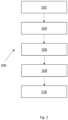
- Fig. 2 shows a method 100 of power loss detection, which is performed by the aircraft galley power system 14.
- the method 100 comprises an initial voltage determination step 102, a subsequent voltage determination step 104, a voltage change determination step 106, a voltage change comparison step 108 and a response step 110.
- the power supply 18 supplies direct current (DC) power to the aircraft galley load 16 until power loss of the power supply 8 occurs.
- DC direct current
- the power supply 8 applies a voltage across terminals (not shown) of the aircraft galley load 16.
- the voltage sensor 22 determines an initial voltage of the power supply 8.
- the voltage sensor measures an initial series of voltages.
- the initial series of voltages comprises a plurality of voltages of the power supply 8 measured over time, for example, with a constant time period between the voltages.
- the voltage sensor 22 measures the initial series of voltages over a time period, referred to as an initial time period.
- the initial time period has a duration of substantially 3 seconds.
- the voltage sensor 22 determines the initial voltage from the initial series of voltages as an average (in the present example, an arithmetic mean) of the voltages of the initial series of voltages. In other examples, the voltage sensor 22 may determine the initial voltage as the average of the initial series of voltages in another manner, for example, as a weighted average or as a median value. In other examples, the voltage sensor 22 may measure only one voltage value to determine the initial voltage, with the initial voltage being determined as the one voltage value.
- the voltage sensor 22 determines a subsequent voltage of the power supply 8.
- the voltage sensor measures a subsequent series of voltages.
- the subsequent series of voltages comprises a plurality of voltages of the power supply 8 measured over time, for example, with a constant time period between the voltages.
- the voltage sensor 22 measures the subsequent series of voltages over a time period, referred to as a subsequent time period.
- the subsequent time period has a duration of substantially 3 seconds.
- the subsequent time period has the same duration as the initial time period.
- initial and subsequent in relation to voltages and time periods are used to indicate those which occur generally earlier or later in time, such that initial voltages/time periods occur at generally earlier times than subsequent voltages/time periods.
- initial is intended to indicate initial in relation to the method 100 (e.g. occurring at the beginning of the method 100), rather than, for example, the absolute initial or first voltages measured on activation of the power supply. It will be understood that the method 100 may be performed on several occasions during activation of the power supply (e.g. periodically), with the initial time period generally occurring later in time for each next occasion that takes place.
- the subsequent time period and the initial time period overlap.
- a selection of the voltages of the initial series of voltages are also in the subsequent series of voltages.
- the subsequent time period begins after the initial time period begins.
- the subsequent time period ends after the initial time period ends.
- the voltage sensor 22 determines the subsequent voltage from the subsequent series of voltages as an average (in the present example, an arithmetic mean) of the voltages of the subsequent series of voltages. In other examples, the voltage sensor 22 may determine the subsequent voltage as the average of the subsequent series of voltages in another manner, for example, as a weighted average or as a median value.
- the voltage sensor 22 may measure only one voltage value (a single voltage, e.g. a current voltage, which may also be referred to as a realtime voltage) to determine the subsequent voltage, with the subsequent voltage being determined as the one voltage value.
- the voltage sensor may still be configured to determine the initial voltage from the initial series of voltages.
- the subsequent voltage may be measured shortly after the end of the initial time period (e.g. the first voltage measured after the end of the initial time period or a voltage measured a fixed interval after the end of the initial time period) or may be measured during the initial time period (e.g. the final voltage measured in the time period).
- the controller 24 determines a voltage change from the initial voltage and the subsequent voltage. In the present example, the controller 24 determines the voltage change as the difference between the initial voltage and the subsequent voltage. In the other examples, the voltage change may be determined differently, for example as a rate of change of voltage over time.
- the controller 24 compares the voltage change to a voltage change threshold. The controller 24 determines that a power loss has occurred in the event that the voltage change exceeds the voltage change threshold.
- the voltage change threshold is variable and is a proportion of the initial voltage.
- the voltage change threshold is 10% of the initial voltage.
- the voltage change threshold may be a fixed value regardless of the initial voltage.
- the controller 24 takes an action in the response step 110.
- the action may comprise controlling the aircraft galley load 16 (or a component thereof) to perform a graceful shutdown or transmitting a shutdown signal to the aircraft galley load 16 to cause the aircraft galley load 16 to perform the graceful shutdown.
- the method 100 occurs multiple times, particularly in the event that power loss does not occur.
- the method 100 may take place regularly e.g. periodically.
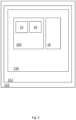
- Fig. 3 shows a second aircraft 210 comprising a second aircraft galley 212.
- the second aircraft galley 212 comprises a second aircraft galley load 216, which as for the aircraft galley load 16, may be a kitchen appliance and/or a communication device.
- the second aircraft galley 212 may comprise a plurality of such second aircraft galley loads 216.
- the second aircraft galley 212 does not comprise a separate aircraft galley power system as described above, with the second aircraft galley 212 itself comprising the power supply 18 and the power loss detector 20.
- the power supply 18 supplies power for the second aircraft galley load 16.
- the power supply receives power from the power source as before.
- the power loss detector 20 operates in the same manner as the aircraft galley 12, performing the method 100. Repeated description of that operation is omitted.
Landscapes
- Physics & Mathematics (AREA)
- General Physics & Mathematics (AREA)
- Engineering & Computer Science (AREA)
- Aviation & Aerospace Engineering (AREA)
- Measurement Of Current Or Voltage (AREA)
Abstract
A power loss detector for an aircraft galley, the aircraft galley comprising a power supply and an aircraft galley load, the power supply configured to supply DC power to an aircraft galley load, the power loss detector comprising: a voltage sensor configured to determine an initial voltage of the power supply and a subsequent voltage of the power supply; and a controller configured to determine from the initial voltage and the subsequent voltage a voltage change, the controller configured to determine a power loss in the event that the voltage change exceeds a voltage change threshold.
Description
- This application relates to a power loss detector, an aircraft galley power system, an aircraft galley, an aircraft and a method.
- Aircraft galleys require DC power to power aircraft galley loads (e.g. kitchen appliances). The voltage at which the DC power is provided may vary between different galleys and different loads, which can present difficulties in detecting power loss within a reasonable response time.
- In a first aspect of the invention, there is provided a power loss detector for an aircraft galley, the aircraft galley comprising a power supply and an aircraft galley load, the power supply configured to supply DC power to an aircraft galley load, the power loss detector comprising: a voltage sensor configured to determine an initial voltage of the power supply and a subsequent voltage of the power supply; and a controller configured to determine from the initial voltage and the subsequent voltage a voltage change, the controller is configured to determine a power loss in the event that the voltage change exceeds a voltage change threshold.
- Power loss may be more reliably and quickly detected by considering voltage change (e.g. in comparison to determining when the supply voltage reaches a fixed threshold), particularly in systems where supply voltage may change or where it may be desirable to use the same type of power loss detector in different systems with different supply voltages. Response time in determining power loss may also be improved in contrast to waiting until supply voltage reaches a fixed, often necessarily lower, threshold.
- In an example, the voltage sensor is configured to measure an initial series of voltages of the power supply across an initial time period, wherein the voltage sensor is configured to determine the initial voltage from the initial series of voltages.
- In an example, the voltage sensor is configured to determine the initial voltage as an average of the voltages of the initial series of voltages.
- In an example, the initial time period has a duration of at least 1 second. In an example, the initial time period has a duration of at least 2 seconds. In an example, the initial time period has a duration of substantially 3 seconds.
- In an example, the voltage sensor is configured to measure a single voltage of the power supply and determine the subsequent voltage as the single voltage. The single voltage may be a current voltage.
- In an example, the voltage sensor is configured to measure a subsequent series of voltages of the power supply across a subsequent time period, wherein the voltage sensor is configured to determine the subsequent voltage from the subsequent series of voltages.
- In an example, the voltage sensor is configured to determine the subsequent voltage as an average of the voltages of the subsequent series of voltages.
- In an example, the subsequent time period has a duration of at least 1 second. In an example, the subsequent time period has a duration of at least 2 seconds. In an example, the subsequent time period has a duration of substantially 3 seconds.
- In an example, the subsequent time period overlaps the earlier time period.
- In an example, the subsequent time period is substantially equal in duration to the earlier time period.
- In an example, the voltage change threshold is at least 5% of the initial voltage. In an example, the voltage change threshold is substantially 10% of the initial voltage.
- In an example, the controller is configured to control a load of the aircraft galley to perform a graceful shutdown in response to the power loss event being determined.
- According to a second aspect, there is provided an aircraft galley load comprising the power loss detector.
- The aircraft galley load may comprise the power supply, the power supply configured to supply DC power to the aircraft galley load.
- The aircraft galley load may be an appliance. The aircraft galley load may be a kitchen appliance.
- According to a third aspect, there is provided an aircraft galley power system comprising the power loss detector and the power supply.
- According to a fourth aspect, there is provided an aircraft galley comprising the aircraft galley load of the second aspect or the aircraft galley power supply of the third aspect.
- According to a fifth aspect, there is provided an aircraft comprising the aircraft galley.
- According to a sixth aspect, there is provided a method of detecting power loss of a power supply in an aircraft galley power system, the method comprising: determining an initial voltage of the power supply and a subsequent voltage of the power supply; determining from the initial voltage and the subsequent voltage a voltage change; and determine a power loss in the event that the voltage change exceeds a voltage change threshold.
- Any of the aspects may comprise any of the features described with respect to any of the other aspects.
- Various examples will now be described with reference to the accompanying drawings in which:
-
Figure 1 shows a schematic of an aircraft comprising an aircraft galley power system; and -
Figure 2 shows a method of detecting power loss; -
Figure 3 shows a schematic of an aircraft comprising an aircraft galley load. -
Fig. 1 shows anaircraft 10. Theaircraft 10 comprises anaircraft galley 12. Theaircraft galley 12 comprises an aircraftgalley power system 14 and anaircraft galley load 16. The aircraftgalley power system 14 is configured to supply power to theaircraft galley load 16, which may comprise, for example, kitchen appliances (e.g. a beverage maker, a refrigerator and a microwave) and/or communication devices. The communication devices may be comprised in the appliances. Theaircraft galley load 16 may comprise a plurality of such appliances and/or devices, with the aircraftgalley power system 14 being configured to apply to all appliances and/or devices. - The aircraft
galley power system 14 comprises apower supply 18 and apower loss detector 20. Thepower loss detector 20 comprises avoltage sensor 22 and acontroller 24. - The
power supply 18 is configured to receive power from a power source (e.g. from an energy storage such as a battery or from an aircraft engine) and to supply the power to theaircraft galley loads 16. Thepower supply 18 is configured to supply low voltage DC power to theaircraft galley loads 16. Thepower supply 18 may comprise DC-DC converters and/or rectifiers, or may receive already converted and/or rectified power, simply passing the power onto theaircraft galley loads 16. -
Fig. 2 shows amethod 100 of power loss detection, which is performed by the aircraftgalley power system 14. Themethod 100 comprises an initialvoltage determination step 102, a subsequentvoltage determination step 104, a voltagechange determination step 106, a voltagechange comparison step 108 and aresponse step 110. - During the
method 100, thepower supply 18 supplies direct current (DC) power to theaircraft galley load 16 until power loss of the power supply 8 occurs. To supply the DC power, the power supply 8 applies a voltage across terminals (not shown) of theaircraft galley load 16. - In the initial
voltage determination step 102, thevoltage sensor 22 determines an initial voltage of the power supply 8. In the present example, the voltage sensor measures an initial series of voltages. The initial series of voltages comprises a plurality of voltages of the power supply 8 measured over time, for example, with a constant time period between the voltages. - The
voltage sensor 22 measures the initial series of voltages over a time period, referred to as an initial time period. The initial time period has a duration of substantially 3 seconds. - The
voltage sensor 22 determines the initial voltage from the initial series of voltages as an average (in the present example, an arithmetic mean) of the voltages of the initial series of voltages. In other examples, thevoltage sensor 22 may determine the initial voltage as the average of the initial series of voltages in another manner, for example, as a weighted average or as a median value. In other examples, thevoltage sensor 22 may measure only one voltage value to determine the initial voltage, with the initial voltage being determined as the one voltage value. - In the subsequent
voltage determination step 104, thevoltage sensor 22 determines a subsequent voltage of the power supply 8. In the present example, the voltage sensor measures a subsequent series of voltages. The subsequent series of voltages comprises a plurality of voltages of the power supply 8 measured over time, for example, with a constant time period between the voltages. - The
voltage sensor 22 measures the subsequent series of voltages over a time period, referred to as a subsequent time period. The subsequent time period has a duration of substantially 3 seconds. The subsequent time period has the same duration as the initial time period. - Herein the terms "initial" and "subsequent" in relation to voltages and time periods are used to indicate those which occur generally earlier or later in time, such that initial voltages/time periods occur at generally earlier times than subsequent voltages/time periods.
- The term "initial" is intended to indicate initial in relation to the method 100 (e.g. occurring at the beginning of the method 100), rather than, for example, the absolute initial or first voltages measured on activation of the power supply. It will be understood that the
method 100 may be performed on several occasions during activation of the power supply (e.g. periodically), with the initial time period generally occurring later in time for each next occasion that takes place. - In the present example, the subsequent time period and the initial time period overlap. A selection of the voltages of the initial series of voltages are also in the subsequent series of voltages. The subsequent time period begins after the initial time period begins. The subsequent time period ends after the initial time period ends.
- The
voltage sensor 22 determines the subsequent voltage from the subsequent series of voltages as an average (in the present example, an arithmetic mean) of the voltages of the subsequent series of voltages. In other examples, thevoltage sensor 22 may determine the subsequent voltage as the average of the subsequent series of voltages in another manner, for example, as a weighted average or as a median value. - In other examples, the
voltage sensor 22 may measure only one voltage value (a single voltage, e.g. a current voltage, which may also be referred to as a realtime voltage) to determine the subsequent voltage, with the subsequent voltage being determined as the one voltage value. In such examples, the voltage sensor may still be configured to determine the initial voltage from the initial series of voltages. The subsequent voltage may be measured shortly after the end of the initial time period (e.g. the first voltage measured after the end of the initial time period or a voltage measured a fixed interval after the end of the initial time period) or may be measured during the initial time period (e.g. the final voltage measured in the time period). - In the voltage
change determination step 106, thecontroller 24 determines a voltage change from the initial voltage and the subsequent voltage. In the present example, thecontroller 24 determines the voltage change as the difference between the initial voltage and the subsequent voltage. In the other examples, the voltage change may be determined differently, for example as a rate of change of voltage over time. - In the voltage
change comparison step 108, thecontroller 24 compares the voltage change to a voltage change threshold. Thecontroller 24 determines that a power loss has occurred in the event that the voltage change exceeds the voltage change threshold. - In the present example, the voltage change threshold is variable and is a proportion of the initial voltage. The voltage change threshold is 10% of the initial voltage. In other examples, the voltage change threshold may be a fixed value regardless of the initial voltage.
- In the event that the power loss has occurred, the
controller 24 takes an action in theresponse step 110. The action may comprise controlling the aircraft galley load 16 (or a component thereof) to perform a graceful shutdown or transmitting a shutdown signal to theaircraft galley load 16 to cause theaircraft galley load 16 to perform the graceful shutdown. - As mentioned above, the
method 100 occurs multiple times, particularly in the event that power loss does not occur. Themethod 100 may take place regularly e.g. periodically. -
Fig. 3 shows asecond aircraft 210 comprising asecond aircraft galley 212. Thesecond aircraft galley 212 comprises a secondaircraft galley load 216, which as for theaircraft galley load 16, may be a kitchen appliance and/or a communication device. Thesecond aircraft galley 212 may comprise a plurality of such second aircraft galley loads 216. - In contrast to in the
aircraft galley 12, thesecond aircraft galley 212 does not comprise a separate aircraft galley power system as described above, with thesecond aircraft galley 212 itself comprising thepower supply 18 and thepower loss detector 20. - The
power supply 18 supplies power for the secondaircraft galley load 16. The power supply receives power from the power source as before. In thesecond aircraft galley 212, thepower loss detector 20 operates in the same manner as theaircraft galley 12, performing themethod 100. Repeated description of that operation is omitted. - While particular functional steps have been described with respect to the
voltage sensor 22 and thecontroller 24, it is possible that some functional steps could be performed with the other of the voltage sensor and the controller. Additionally, some functional steps may be performed in a different processor, for example, a remotely located processor. Analogue or digital circuitry may also be used in place of a processor - Various aspects of the apparatus disclosed in the various embodiments may be used alone, in combination, or in a variety of arrangements not specifically discussed in the embodiments described in the foregoing and this disclosure is therefore not limited in its application to the details and arrangement of components set forth in the foregoing description or illustrated in the drawings. For example, aspects described in one embodiment may be combined in any manner with aspects described in other embodiments. Although particular embodiments have been shown and described, it will be obvious to those skilled in the art that changes and modifications may be made without departing from this invention in its broader aspects. The scope of the following claims should not be limited by the embodiments set forth in the examples, but should be given the broadest reasonable interpretation consistent with the description as a whole.
Claims (14)
- A power loss detector for an aircraft galley, the aircraft galley comprising a power supply and an aircraft galley load, the power supply configured to supply DC power to an aircraft galley load, the power loss detector comprising:a voltage sensor configured to determine an initial voltage of the power supply and a subsequent voltage of the power supply; anda controller configured to determine from the initial voltage and the subsequent voltage a voltage change, the controller configured to determine a power loss in the event that the voltage change exceeds a voltage change threshold.
- A power loss detector according to claim 1, wherein the voltage sensor is configured to measure an initial series of voltages of the power supply across an initial time period, wherein the voltage sensor is configured to determine the initial voltage from the initial series of voltages.
- A power loss detector according to claim 2, wherein the voltage sensor is configured to determine the initial voltage as an average of the voltages of the initial series of voltages.
- A power loss detector according to claim 2 or 3, wherein the initial time period has a duration of at least 1 second.
- A power loss detector according to any preceding claim, wherein the voltage sensor is configured to measure a single voltage of the power supply and determine the subsequent voltage as the single voltage.
- A power loss detector according to any preceding claim, wherein the voltage change threshold is a proportion of the initial voltage.
- A power loss detector according to any preceding claim, wherein the controller is configured to control a load of the aircraft galley to perform a graceful shutdown in response to the power loss event being determined.
- An aircraft galley load comprising the power loss detector according to any preceding claim.
- An aircraft galley load according to claim 8 and comprising the power supply, the power supply configured to supply DC power to the aircraft galley load.
- An aircraft galley load according to claim 8 or 9, wherein the aircraft galley load is a kitchen appliance.
- An aircraft galley power system comprising the power loss detector according to any of claims 1 to 7 and the power supply, the power supply configured to supply DC power to the aircraft galley load.
- An aircraft galley comprising an aircraft galley load according to any of claims 8-10 or an aircraft galley power system according to claim 11.
- An aircraft comprising the aircraft galley of claim 12.
- A method detecting power loss of a power supply in an aircraft galley power system, the method comprising:determining an initial voltage of the power supply and a subsequent voltage of the power supply;determining from the initial voltage and the subsequent voltage a voltage change;anddetermine a power loss in the event that the voltage change exceeds a voltage change threshold.
Priority Applications (2)
| Application Number | Priority Date | Filing Date | Title |
|---|---|---|---|
| EP23171281.1A EP4459303A1 (en) | 2023-05-03 | 2023-05-03 | Power loss detector |
| US18/639,339 US20240369609A1 (en) | 2023-05-03 | 2024-04-18 | Power loss detector |
Applications Claiming Priority (1)
| Application Number | Priority Date | Filing Date | Title |
|---|---|---|---|
| EP23171281.1A EP4459303A1 (en) | 2023-05-03 | 2023-05-03 | Power loss detector |
Publications (1)
| Publication Number | Publication Date |
|---|---|
| EP4459303A1 true EP4459303A1 (en) | 2024-11-06 |
Family
ID=86328842
Family Applications (1)
| Application Number | Title | Priority Date | Filing Date |
|---|---|---|---|
| EP23171281.1A Pending EP4459303A1 (en) | 2023-05-03 | 2023-05-03 | Power loss detector |
Country Status (2)
| Country | Link |
|---|---|
| US (1) | US20240369609A1 (en) |
| EP (1) | EP4459303A1 (en) |
Citations (3)
| Publication number | Priority date | Publication date | Assignee | Title |
|---|---|---|---|---|
| US20070296273A1 (en) * | 2006-06-21 | 2007-12-27 | Airbus Deutschland Gmbh | Power supply network with integrated undervoltage protection in a passenger aircraft |
| CN112946347A (en) * | 2021-01-27 | 2021-06-11 | 许继集团有限公司 | Power supply over-voltage and under-voltage alarm monitoring system |
| US20220137150A1 (en) * | 2020-11-05 | 2022-05-05 | Samsung Sdi Co., Ltd. | Battery defect screening device and method |
-
2023
- 2023-05-03 EP EP23171281.1A patent/EP4459303A1/en active Pending
-
2024
- 2024-04-18 US US18/639,339 patent/US20240369609A1/en active Pending
Patent Citations (3)
| Publication number | Priority date | Publication date | Assignee | Title |
|---|---|---|---|---|
| US20070296273A1 (en) * | 2006-06-21 | 2007-12-27 | Airbus Deutschland Gmbh | Power supply network with integrated undervoltage protection in a passenger aircraft |
| US20220137150A1 (en) * | 2020-11-05 | 2022-05-05 | Samsung Sdi Co., Ltd. | Battery defect screening device and method |
| CN112946347A (en) * | 2021-01-27 | 2021-06-11 | 许继集团有限公司 | Power supply over-voltage and under-voltage alarm monitoring system |
Non-Patent Citations (2)
| Title |
|---|
| LEE YOUBOK: "Intelligent real-time monitoring and management of battery power", 1 April 2018 (2018-04-01), XP093084153, Retrieved from the Internet <URL:https://cdn.weka-fachmedien.de/whitepaper/files/107_mca488wp_battery_power_algorithm.pdf> [retrieved on 20230921] * |
| MONNAPPA AKSHITH ET AL: "Design and Development of Battery Capacity Management(BCM) Gauge", 1 May 2018 (2018-05-01), XP093084152, Retrieved from the Internet <URL:https://www.ijera.com/papers/Vol8_issue5/Part-2/C0805021015.pdf> [retrieved on 20230921], DOI: 10.9790/9622-0805021015 * |
Also Published As
| Publication number | Publication date |
|---|---|
| US20240369609A1 (en) | 2024-11-07 |
Similar Documents
| Publication | Publication Date | Title |
|---|---|---|
| US7365525B2 (en) | Protection for switched step up/step down regulators | |
| US12261447B2 (en) | On-grid/off-grid scheduling method and apparatus, and energy storage power supply system | |
| US8624570B2 (en) | Digitally controlling a power converter | |
| US8488339B2 (en) | Switching power supply | |
| US6809678B2 (en) | Data processor controlled DC to DC converter system and method of operation | |
| US20220231596A1 (en) | Power supply with controlled shunting element | |
| EP3054573B1 (en) | Methods and systems for improving load transient response in power conversion systems | |
| US9354650B2 (en) | Switching power supply circuit | |
| US5790392A (en) | Intelligent power supply with staged loading capability | |
| US20160254753A1 (en) | Detecting open connection of auxiliary winding in a switching mode power supply | |
| CN102594115A (en) | Adaptively controlled soft start-up scheme for switching power converters | |
| US20140119084A1 (en) | AC Input Voltage Detection Circuit and AC/DC Power Source | |
| US8659277B2 (en) | Current providing method and current providing system | |
| US4531214A (en) | Power loss analyzer circuit | |
| US9444356B2 (en) | Power supply device and power supply switching method | |
| CA2136384A1 (en) | Microprocessor watchdog circuit | |
| CN112290800A (en) | X capacitor discharge control circuit and method and switching power supply | |
| US6101105A (en) | Apparatus and method for identifying an unregulated DC bus voltage | |
| US10811877B2 (en) | Power supply system and power supply apparatus | |
| US20240369609A1 (en) | Power loss detector | |
| EP3796498A1 (en) | Self-power relay and method for preventing malfunction thereof | |
| US20250277873A1 (en) | Output Voltage Sense Protection Device and Method | |
| US11942813B2 (en) | Battery-system control method and battery system | |
| US12483024B2 (en) | Power supply device, control device for power supply circuit, and program | |
| WO2011149928A1 (en) | System and method for low battery detection |
Legal Events
| Date | Code | Title | Description |
|---|---|---|---|
| PUAI | Public reference made under article 153(3) epc to a published international application that has entered the european phase |
Free format text: ORIGINAL CODE: 0009012 |
|
| STAA | Information on the status of an ep patent application or granted ep patent |
Free format text: STATUS: THE APPLICATION HAS BEEN PUBLISHED |
|
| AK | Designated contracting states |
Kind code of ref document: A1 Designated state(s): AL AT BE BG CH CY CZ DE DK EE ES FI FR GB GR HR HU IE IS IT LI LT LU LV MC ME MK MT NL NO PL PT RO RS SE SI SK SM TR |
|
| STAA | Information on the status of an ep patent application or granted ep patent |
Free format text: STATUS: REQUEST FOR EXAMINATION WAS MADE |
|
| 17P | Request for examination filed |
Effective date: 20250506 |