EP4459301A1 - High-speed battery defect inspection method - Google Patents
High-speed battery defect inspection method Download PDFInfo
- Publication number
- EP4459301A1 EP4459301A1 EP23882832.1A EP23882832A EP4459301A1 EP 4459301 A1 EP4459301 A1 EP 4459301A1 EP 23882832 A EP23882832 A EP 23882832A EP 4459301 A1 EP4459301 A1 EP 4459301A1
- Authority
- EP
- European Patent Office
- Prior art keywords
- battery
- analysis target
- set frequency
- activation
- real part
- Prior art date
- Legal status (The legal status is an assumption and is not a legal conclusion. Google has not performed a legal analysis and makes no representation as to the accuracy of the status listed.)
- Granted
Links
Images


Classifications
-
- G—PHYSICS
- G01—MEASURING; TESTING
- G01R—MEASURING ELECTRIC VARIABLES; MEASURING MAGNETIC VARIABLES
- G01R31/00—Arrangements for testing electric properties; Arrangements for locating electric faults; Arrangements for electrical testing characterised by what is being tested not provided for elsewhere
- G01R31/36—Arrangements for testing, measuring or monitoring the electrical condition of accumulators or electric batteries, e.g. capacity or state of charge [SoC]
- G01R31/392—Determining battery ageing or deterioration, e.g. state of health
-
- B—PERFORMING OPERATIONS; TRANSPORTING
- B60—VEHICLES IN GENERAL
- B60L—PROPULSION OF ELECTRICALLY-PROPELLED VEHICLES; SUPPLYING ELECTRIC POWER FOR AUXILIARY EQUIPMENT OF ELECTRICALLY-PROPELLED VEHICLES; ELECTRODYNAMIC BRAKE SYSTEMS FOR VEHICLES IN GENERAL; MAGNETIC SUSPENSION OR LEVITATION FOR VEHICLES; MONITORING OPERATING VARIABLES OF ELECTRICALLY-PROPELLED VEHICLES; ELECTRIC SAFETY DEVICES FOR ELECTRICALLY-PROPELLED VEHICLES
- B60L3/00—Electric devices on electrically-propelled vehicles for safety purposes; Monitoring operating variables, e.g. speed, deceleration or energy consumption
- B60L3/0023—Detecting, eliminating, remedying or compensating for drive train abnormalities, e.g. failures within the drive train
- B60L3/0046—Detecting, eliminating, remedying or compensating for drive train abnormalities, e.g. failures within the drive train relating to electric energy storage systems, e.g. batteries or capacitors
-
- B—PERFORMING OPERATIONS; TRANSPORTING
- B60—VEHICLES IN GENERAL
- B60L—PROPULSION OF ELECTRICALLY-PROPELLED VEHICLES; SUPPLYING ELECTRIC POWER FOR AUXILIARY EQUIPMENT OF ELECTRICALLY-PROPELLED VEHICLES; ELECTRODYNAMIC BRAKE SYSTEMS FOR VEHICLES IN GENERAL; MAGNETIC SUSPENSION OR LEVITATION FOR VEHICLES; MONITORING OPERATING VARIABLES OF ELECTRICALLY-PROPELLED VEHICLES; ELECTRIC SAFETY DEVICES FOR ELECTRICALLY-PROPELLED VEHICLES
- B60L3/00—Electric devices on electrically-propelled vehicles for safety purposes; Monitoring operating variables, e.g. speed, deceleration or energy consumption
- B60L3/12—Recording operating variables ; Monitoring of operating variables
-
- B—PERFORMING OPERATIONS; TRANSPORTING
- B60—VEHICLES IN GENERAL
- B60L—PROPULSION OF ELECTRICALLY-PROPELLED VEHICLES; SUPPLYING ELECTRIC POWER FOR AUXILIARY EQUIPMENT OF ELECTRICALLY-PROPELLED VEHICLES; ELECTRODYNAMIC BRAKE SYSTEMS FOR VEHICLES IN GENERAL; MAGNETIC SUSPENSION OR LEVITATION FOR VEHICLES; MONITORING OPERATING VARIABLES OF ELECTRICALLY-PROPELLED VEHICLES; ELECTRIC SAFETY DEVICES FOR ELECTRICALLY-PROPELLED VEHICLES
- B60L58/00—Methods or circuit arrangements for monitoring or controlling batteries or fuel cells, specially adapted for electric vehicles
- B60L58/10—Methods or circuit arrangements for monitoring or controlling batteries or fuel cells, specially adapted for electric vehicles for monitoring or controlling batteries
- B60L58/16—Methods or circuit arrangements for monitoring or controlling batteries or fuel cells, specially adapted for electric vehicles for monitoring or controlling batteries responding to battery ageing, e.g. to the number of charging cycles or the state of health [SoH]
-
- G—PHYSICS
- G01—MEASURING; TESTING
- G01R—MEASURING ELECTRIC VARIABLES; MEASURING MAGNETIC VARIABLES
- G01R23/00—Arrangements for measuring frequencies; Arrangements for analysing frequency spectra
- G01R23/02—Arrangements for measuring frequency, e.g. pulse repetition rate; Arrangements for measuring period of current or voltage
-
- G—PHYSICS
- G01—MEASURING; TESTING
- G01R—MEASURING ELECTRIC VARIABLES; MEASURING MAGNETIC VARIABLES
- G01R31/00—Arrangements for testing electric properties; Arrangements for locating electric faults; Arrangements for electrical testing characterised by what is being tested not provided for elsewhere
- G01R31/36—Arrangements for testing, measuring or monitoring the electrical condition of accumulators or electric batteries, e.g. capacity or state of charge [SoC]
- G01R31/389—Measuring internal impedance, internal conductance or related variables
-
- H—ELECTRICITY
- H01—ELECTRIC ELEMENTS
- H01M—PROCESSES OR MEANS, e.g. BATTERIES, FOR THE DIRECT CONVERSION OF CHEMICAL ENERGY INTO ELECTRICAL ENERGY
- H01M10/00—Secondary cells; Manufacture thereof
- H01M10/42—Methods or arrangements for servicing or maintenance of secondary cells or secondary half-cells
-
- G—PHYSICS
- G01—MEASURING; TESTING
- G01R—MEASURING ELECTRIC VARIABLES; MEASURING MAGNETIC VARIABLES
- G01R31/00—Arrangements for testing electric properties; Arrangements for locating electric faults; Arrangements for electrical testing characterised by what is being tested not provided for elsewhere
- G01R31/36—Arrangements for testing, measuring or monitoring the electrical condition of accumulators or electric batteries, e.g. capacity or state of charge [SoC]
- G01R31/396—Acquisition or processing of data for testing or for monitoring individual cells or groups of cells within a battery
-
- H—ELECTRICITY
- H01—ELECTRIC ELEMENTS
- H01M—PROCESSES OR MEANS, e.g. BATTERIES, FOR THE DIRECT CONVERSION OF CHEMICAL ENERGY INTO ELECTRICAL ENERGY
- H01M10/00—Secondary cells; Manufacture thereof
- H01M10/42—Methods or arrangements for servicing or maintenance of secondary cells or secondary half-cells
- H01M10/4285—Testing apparatus
-
- Y—GENERAL TAGGING OF NEW TECHNOLOGICAL DEVELOPMENTS; GENERAL TAGGING OF CROSS-SECTIONAL TECHNOLOGIES SPANNING OVER SEVERAL SECTIONS OF THE IPC; TECHNICAL SUBJECTS COVERED BY FORMER USPC CROSS-REFERENCE ART COLLECTIONS [XRACs] AND DIGESTS
- Y02—TECHNOLOGIES OR APPLICATIONS FOR MITIGATION OR ADAPTATION AGAINST CLIMATE CHANGE
- Y02E—REDUCTION OF GREENHOUSE GAS [GHG] EMISSIONS, RELATED TO ENERGY GENERATION, TRANSMISSION OR DISTRIBUTION
- Y02E60/00—Enabling technologies; Technologies with a potential or indirect contribution to GHG emissions mitigation
- Y02E60/10—Energy storage using batteries
Definitions
- the present disclosure relates to high-speed battery defect inspection methods and more particularly, to high-speed battery defect inspection methods for determining a battery defect in a short time by predicting deterioration characteristics of a battery formed by stacking a plurality of monocells.
- Products such as ESSs and vehicle batteries equipped with low-voltage defective cells which are shipped, exhibit significant instability in performance over a long period of time and may reduce product reliability.
- HPCD high pressure current detection
- the present disclosure relates to high-speed battery defect inspection methods, and more particularly, provides high-speed battery defect inspection methods by predicting deterioration characteristics of a battery formed by stacking a plurality of monocells and determining a battery defect in a short time.
- a high-speed battery defect inspection method of the present disclosure may include
- a high-speed battery defect inspection method of the present disclosure may detect low-voltage defective batteries in a short time, and may be capable of inspecting thousands to tens of thousands of batteries per second.
- the high-speed battery defect inspection method of the present disclosure is capable of performing non-destructive inspection on finished batteries, and may be applicable to batteries in mass production lines and batteries that have already been produced.
- the high-speed battery defect inspection method of the present disclosure significantly reduces inspection time, and may be capable of determining defects even in batteries that have not been inspected.
- a high-speed battery defect inspection method of the present disclosure may include
- the set frequency may be from 10 -2 kHz to 7 MHz.
- the analysis target battery may include a plurality of monocells.
- the high-speed battery defect inspection method of the present disclosure may further include
- the reference battery may have a dOCV of 300 mV or greater or three sigma or more.
- the set frequency calculation step (s20) may include a variable separation step (s21) of separating the plurality of reference impedances into real part values Z SR and imaginary part values Zsi, a function fitting step (s22) of fitting a function f to relate the Z SR to the Zsi, and a set frequency acquisition step (s23) of obtaining the set frequency based on the function.
- the function f may be fitted by an equation of Formula 1 below.
- Z SR f Z SI .
- the set frequency may be selected from frequencies satisfying an equation of Formula 2 below for a section in which Zsi has a value greater than 0. ⁇ ⁇ ⁇ df Z SI dZ SI ⁇ ⁇ wherein ⁇ is from 0.0 to 0.2.
- ⁇ may be 0.
- the analysis target battery may be determined as a defective battery when the real part resistance is at least 30% greater than the Zsi value satisfying the equation of Formula 2.
- a battery activation method of the present disclosure may include
- the battery activation method of the present disclosure may further include
- FIG. 1 is a block diagram illustrating a high-speed battery defect inspection method of the present disclosure.
- FIG. 2 is a graph illustrating a general Nyquist diagram.
- FIG. 3 is a graph comparing impedance values of a normal battery and a defective battery.
- FIG. 4 is a block diagram illustrating another embodiment of a high-speed battery defect inspection method of the present disclosure.
- FIG. 5 is a block diagram illustrating a set frequency step.
- ahigh-speed battery defect inspection method of the present disclosure may include
- the analysis target battery may include a plurality of monocells.
- the monocell may be a unit cell having different types of electrodes located on both sides of the outermost surface when one or more cathodes and one or more anodes are stacked with a separator therebetween to form an electrode assembly.
- a monocell may be a unit cell having an electrode assembly having a structure in which a cathode-separator-anode are stacked in that order.
- the monocell may be a unit cell having an electrode assembly having a structure in which a cathode-separator-anode-separator-cathode-separator-anode are stacked in that order.
- the cathode may be a cathode current collector coated with a cathode active material.
- the anode may be an anode current collector coated with an anode active material.
- the separator may be an insulator through which ions pass.
- the set frequency may be 10 -2 kHz to 7 MHz.
- the set frequency In the case of a low-voltage defective battery, it has an impedance value different from that of a normal battery at a high frequency, and in particular, shows a difference in a real component among impedance values.
- a graph on the complex plane as shown in FIG. 2 may be obtained. Specifically, in the impedance value corresponding to each frequency, a value obtained by multiplying an imaginary part by (-) and a value of the real part may be displayed as coordinates to obtain a Nyquist diagram as shown in FIG. 2 .
- the high-speed battery defect inspection method of the present disclosure may be capable of high-speed discriminating low-voltage defects of a battery based on real part values in the second quadrant of the graph of FIG. 2 .
- FIG. 3 is a graph illustrating impedance spectroscopy measurement results for 15 batteries.
- five graphs of A_1, A_2, A_3, A_4 and A_5 are graphs for normal batteries
- five graphs E_1, E_2, E_3, E_4, and E_5 are graphs for grade E defective batteries
- five graphs L_1, L_2, L_3, L_4, and L_5 are graphs for grade L defective batteries.
- the grade E defective battery may be a defective battery that exhibits absolute OCV decrease.
- the grade L defective battery may be a defective battery that exhibits relative OCV decrease.
- FIG. 3 is a graph illustrating impedance spectroscopy measurement results for 15 batteries.
- five graphs of A_1, A_2, A_3, A_4 and A_5 are graphs for normal batteries
- five graphs E_1, E_2, E_3, E_4, and E_5 are graphs for grade E defective batteries
- five graphs L_1, L_2, L_3, L_4, and L_5 are
- the graphs of EIS measured values of low-voltage defective batteries overlap each other regardless of the defect grade, but the graphs of normal batteries exhibit different behaviors from those of defective batteries.
- the measured impedance value of about 10 kHz normal batteries appear in area A
- grade E defective batteries and grade L defective batteries appear in area B.
- the set frequency may be a frequency selected from 10 -2 kHz to 7 MHz.
- the set frequency may be a frequency selected from 10 -1 kHz to 10 2 kHz.
- the frequency range of 10 -2 kHz to 7 MHz the low-voltage defective battery has an abnormal increase in the real part resistance value, and using this, it is possible to determine whether the battery is a low-voltage defective battery.
- high-speed battery defect inspection methods of the present disclosure may further include prior to the analysis target impedance measurement step (s30),
- the high-speed battery defect inspection method of the present disclosure may obtain an optimal set frequency capable of accurately detecting low-voltage defective batteries, by performing the reference impedance measurement step (s10) and the set frequency calculation step (s20), prior to the analysis target impedance measurement step (s30).
- the reference battery may have a delta open circuit voltage (dOCV) of 300 mV or more or 3 sigma or more.
- the reference battery which is a low-voltage defective battery, may be obtained as a battery that has been inspected as a defective battery in the mass production process or a battery subjected to defective conditions such as electrode folding and active material application area defect.
- the reference impedance measurement step (s10) may be performed by impedance spectroscopy (EIS). Thus, a reference impedance value corresponding to each of the plurality of frequency values may be obtained.
- EIS impedance spectroscopy
- the set frequency calculation step (s20) may include a variable separation step (s21) of separating the plurality of reference impedances into real part values Z SR and imaginary part values Zsi, a function fitting step (s22) of obtaining a function f to relate the Z SR to the Zsi, and a set frequency acquisition step (s23) of obtaining the set frequency based on the function.
- the function f may be fitted by Formula 1 below.
- Z SR f Z SI .
- the function f may be obtained in the form of a function in which real part values Z SR are dependent variables and imaginary part values Zsi are independent variables.
- the set frequency may be selected from frequencies satisfying Formula 2 below for a section in which Zsi has a value greater than 0. ⁇ ⁇ ⁇ df Z SI dZ SI ⁇ ⁇ .
- ⁇ is a real number of from 0.0 to 0.2.
- ⁇ may be determined in consideration of tolerances of specifications and capacities of reference batteries, materials and structures of electrode materials, and the like.
- ⁇ may be determined in consideration of a deviation value of reference impedance values obtained for a plurality of reference batteries.
- ⁇ may be zero.
- a frequency when a value obtained by differentiating the function f by Zsi is 0 may be obtained as the set frequency.
- a frequency value when the function f has a maximum value may be obtained as the set frequency.
- the analysis target battery may be determined as a defective battery when the real part resistance is at least 30% greater than a Zsi value satisfying the Formula 2.
- the function f may have a maximum value with respect to the set frequency, and the real part resistance value may have an abnormally large value.
- the real part resistance value of the low-voltage defective battery is more than twice as large as the real part resistance value of the normal defective battery. Therefore, when the real part resistance is at least 30% or more or 50% or more greater than the Zsi values that satisfy Formula 2 above, the analysis target battery may be determined as a low-voltage defective battery.
- a battery activation method applying the high-speed battery defect inspection method of the present disclosure may include
- the activation target battery prepared in the activation battery preparation step may be a battery that has completed a packaging process.
- the time required for battery defect inspection before shipment may be significantly reduced.
- the battery activation method of the present disclosure may further include between the activation battery preparation step and the charging/discharging step, a pre-inspection step of pre-inspecting the activation target battery by performing the high-speed battery defect inspection method of the present disclosure using the activation target battery as the analysis target battery.
- the battery activation method of the present disclosure may prevent the charging/discharging process and the aging process from being performed on the defective battery by primarily screening defective batteries before the charging/discharging process and the aging process, and defective batteries that may occur during the solid electrolyte interphase (SEI) layer formation process may be removed again by secondarily screening defective batteries after the aging process.
- SEI solid electrolyte interphase
- the real part resistance values at a frequency of 10 kHz corresponding to the set frequency were measured as 500 ⁇ , 480 ⁇ , 470 ⁇ , 490 ⁇ , and 520 ⁇ , respectively, in the five grade E defective batteries, the real part resistance values at a frequency of 10 kHz corresponding to the set frequency were measured as 1160 ⁇ , 1140 ⁇ , 1110 ⁇ , 1130 ⁇ and 1110 ⁇ , respectively, and in the five grade L defective batteries, the real part resistance values at a frequency of 10 kHz corresponding to the set frequency were measured as 1120 ⁇ , 1070 ⁇ , 1150 ⁇ , 1140 ⁇ , and 1170 ⁇ , respectively.
- High-speed battery defect inspection methods of the present disclosure may detect low-voltage defective batteries in a short time, and may be capable of inspecting thousands to tens of thousands of batteries per second.
- the high-speed battery defect inspection methods of the present disclosure is capable of performing non-destructive inspection on finished batteries, and may be applicable to batteries in mass production lines and batteries that have already been produced.
- the high-speed battery defect inspection methods of the present disclosure significantly reduce inspection time, and may be capable of determining defects even in batteries that have not been inspected.
Landscapes
- Engineering & Computer Science (AREA)
- General Physics & Mathematics (AREA)
- Physics & Mathematics (AREA)
- Power Engineering (AREA)
- Sustainable Energy (AREA)
- Transportation (AREA)
- Mechanical Engineering (AREA)
- Sustainable Development (AREA)
- Life Sciences & Earth Sciences (AREA)
- Manufacturing & Machinery (AREA)
- Chemical & Material Sciences (AREA)
- Chemical Kinetics & Catalysis (AREA)
- Electrochemistry (AREA)
- General Chemical & Material Sciences (AREA)
- Secondary Cells (AREA)
- Tests Of Electric Status Of Batteries (AREA)
Abstract
Description
- The present application claims the benefit of priority based on
Korean Patent Application No. 10-2022-0140870 filed on October 28, 2022 - The present disclosure relates to high-speed battery defect inspection methods and more particularly, to high-speed battery defect inspection methods for determining a battery defect in a short time by predicting deterioration characteristics of a battery formed by stacking a plurality of monocells.
- In the case of a medium or large-sized battery in which a plurality of monocells are stacked, there is a problem in that some monocells inside exhibit a low-voltage defect phenomenon (a phenomenon in which the potential of a specific monocell decreases) for which the cause is unknown, and a defect phenomenon in which the capacity of all cells degrades.
- Products, such as ESSs and vehicle batteries equipped with low-voltage defective cells which are shipped, exhibit significant instability in performance over a long period of time and may reduce product reliability.
- Conventionally, battery voltage tracking is performed to detect low-voltage defective batteries in a battery shipping stage. In the case of battery voltage tracking, it generally took a long time of 2 weeks or more. In addition, there is a high pressure current detection (HPCD) inspection method that considers the main cause of the low-voltage defect as the folding phenomenon of the separator, but there is a limit to detecting by the HPCD inspection method.
- Therefore, there is a need for an inspection method capable of detecting low-voltage defective cells with existing inspection methods and simultaneously inspecting all of the cells in a short time.
- The present disclosure relates to high-speed battery defect inspection methods, and more particularly, provides high-speed battery defect inspection methods by predicting deterioration characteristics of a battery formed by stacking a plurality of monocells and determining a battery defect in a short time.
- Technical objects to be achieved by the present disclosure are not limited to the technical objects mentioned above, and other technical objects not mentioned will be clearly understood by those skilled in the art from the description below.
- A high-speed battery defect inspection method of the present disclosure may include
- an analysis target impedance measurement step (s30) of obtaining an analysis target impedance which is an impedance of an analysis target battery by applying alternating current of a set frequency to the analysis target battery;
- a real part resistance extraction step (s40) of extracting a real part value as a real part resistance from the analysis target impedance; and
- a defect determination step (s50) of determining a defect of the analysis target battery based on the real part resistance,
- wherein the set frequency is selected from frequencies when an imaginary part resistance which is an imaginary part value of the analysis target impedance is greater than 0.
- A high-speed battery defect inspection method of the present disclosure may detect low-voltage defective batteries in a short time, and may be capable of inspecting thousands to tens of thousands of batteries per second.
- The high-speed battery defect inspection method of the present disclosure is capable of performing non-destructive inspection on finished batteries, and may be applicable to batteries in mass production lines and batteries that have already been produced.
- Compared to conventional methods, the high-speed battery defect inspection method of the present disclosure significantly reduces inspection time, and may be capable of determining defects even in batteries that have not been inspected.
-
-
FIG. 1 is a block diagram illustrating a high-speed battery defect inspection method of the present disclosure. -
FIG. 2 is a graph illustrating a general Nyquist diagram. -
FIG. 3 is a graph comparing impedance values of a normal battery and a defective battery. -
FIG. 4 is a block diagram illustrating another embodiment of a high-speed battery defect inspection method of the present disclosure. -
FIG. 5 is a block diagram illustrating a set frequency step. - A high-speed battery defect inspection method of the present disclosure may include
- an analysis target impedance measurement step (s30) of obtaining an analysis target impedance which is impedance of an analysis target battery measured by applying an alternating current at a set frequency to the analysis target battery;
- a real part resistance extraction step (s40) of extracting a real part value as a real part resistance from the analysis target impedance; and
- a defect determination step (s50) of determining a defect of the analysis target battery based on the real part resistance,
- wherein the set frequency is selected from frequencies in which an imaginary part value of the analysis target impedance is greater than 0.
- In the high-speed battery defect inspection method of the present disclosure, the set frequency may be from 10-2 kHz to 7 MHz.
- In the high-speed battery defect inspection method of the present disclosure, the analysis target battery may include a plurality of monocells.
- The high-speed battery defect inspection method of the present disclosure may further include
- prior to the analysis target impedance measurement step (s30),
- a reference impedance measurement step (s10) of obtaining a plurality of reference impedances for a plurality of frequencies by applying an alternating current to a reference battery at varying frequencies; and
- a set frequency calculation step (s20) of calculating the set frequency based on the plurality of reference impedances.
- In the high-speed battery defect inspection method of the present disclosure, the reference battery may have a dOCV of 300 mV or greater or three sigma or more.
- In the high-speed battery defect inspection method of the present disclosure, the set frequency calculation step (s20) may include a variable separation step (s21) of separating the plurality of reference impedances into real part values ZSR and imaginary part values Zsi, a function fitting step (s22) of fitting a function f to relate the ZSR to the Zsi, and a set frequency acquisition step (s23) of obtaining the set frequency based on the function.
- In the function fitting step (s22) of the high-speed battery defect inspection method of the present disclosure, the function f may be fitted by an equation of Formula 1 below.

- In the set frequency acquisition step (s23) of the high-speed battery defect inspection method of the present disclosure, the set frequency may be selected from frequencies satisfying an equation of
Formula 2 below for a section in which Zsi has a value greater than 0.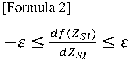
wherein ε is from 0.0 to 0.2. - In the set frequency acquisition step of the high-speed battery defect inspection method of the present disclosure, ε may be 0.
- In the defect determination step (s50) of the high-speed battery defect inspection method of the present disclosure, the analysis target battery may be determined as a defective battery when the real part resistance is at least 30% greater than the Zsi value satisfying the equation of
Formula 2. - A battery activation method of the present disclosure may include
- an activation battery preparation step of assembling an activation target battery;
- a charging/discharging step of charging or discharging the activation target battery;
- a stabilization step of stabilizing the activation target battery by storing the activation target battery for a predetermined period of time at a set temperature and a set humidity; and
- a defect screening step of finally screening defective batteries by performing the high-speed battery defect inspection method using the activation target battery as the analysis target battery.
- The battery activation method of the present disclosure may further include
- between the activation battery preparation step and the charging/discharging step,
- a pre-inspection step of pre-inspecting the activation target battery by performing the high-speed battery defect inspection method using the activation target battery as the analysis target battery.
- Hereinafter, embodiments according to the present disclosure will be described in detail with reference to the accompanying drawings. In this process, the size or shape of the components shown in the drawings may be exaggerated for clarity and convenience of explanation. In addition, terms specifically defined in consideration of the configuration and operation of the present disclosure may vary according to the intentions or customs of users and operators. Definitions of these terms should be made based on the content throughout this specification.
-
FIG. 1 is a block diagram illustrating a high-speed battery defect inspection method of the present disclosure.FIG. 2 is a graph illustrating a general Nyquist diagram.FIG. 3 is a graph comparing impedance values of a normal battery and a defective battery.FIG. 4 is a block diagram illustrating another embodiment of a high-speed battery defect inspection method of the present disclosure.FIG. 5 is a block diagram illustrating a set frequency step. - Hereinafter, with reference to
FIGS. 1 to 5 , high-speed battery defect inspection methods of the present disclosure will be described in detail. - As shown in
FIG. 1 , ahigh-speed battery defect inspection method of the present disclosure may include - an analysis target impedance measurement step (s30) of obtaining an analysis target impedance which is an impedance of an analysis target battery by applying an alternating current at a set frequency to the analysis target battery;
- a real part resistance extraction step (s40) of extracting a real part value as a real part resistance from the analysis target impedance; and
- a defect determination step (s50) of determining a defect of the analysis target battery based on the real part resistance,
- wherein the set frequency is selected from frequencies in which an imaginary part value of the analysis target impedance is greater than 0.
- In the high-speed battery defect inspection methods of the present disclosure, the analysis target battery may include a plurality of monocells.
- The monocell may be a unit cell having different types of electrodes located on both sides of the outermost surface when one or more cathodes and one or more anodes are stacked with a separator therebetween to form an electrode assembly. For example, a monocell may be a unit cell having an electrode assembly having a structure in which a cathode-separator-anode are stacked in that order. For another example, the monocell may be a unit cell having an electrode assembly having a structure in which a cathode-separator-anode-separator-cathode-separator-anode are stacked in that order.
- The cathode may be a cathode current collector coated with a cathode active material.
- The anode may be an anode current collector coated with an anode active material.
- The separator may be an insulator through which ions pass.
- In the analysis target impedance measurement step (s30), the set frequency may be 10-2 kHz to 7 MHz. In the case of a low-voltage defective battery, it has an impedance value different from that of a normal battery at a high frequency, and in particular, shows a difference in a real component among impedance values.
- When impedance spectroscopy (EIS) is performed on the battery, a graph on the complex plane as shown in
FIG. 2 may be obtained. Specifically, in the impedance value corresponding to each frequency, a value obtained by multiplying an imaginary part by (-) and a value of the real part may be displayed as coordinates to obtain a Nyquist diagram as shown inFIG. 2 . The high-speed battery defect inspection method of the present disclosure may be capable of high-speed discriminating low-voltage defects of a battery based on real part values in the second quadrant of the graph ofFIG. 2 . -
FIG. 3 is a graph illustrating impedance spectroscopy measurement results for 15 batteries. InFIG. 3 , five graphs of A_1, A_2, A_3, A_4 and A_5 are graphs for normal batteries, five graphs E_1, E_2, E_3, E_4, and E_5 are graphs for grade E defective batteries, and five graphs L_1, L_2, L_3, L_4, and L_5 are graphs for grade L defective batteries. The grade E defective battery may be a defective battery that exhibits absolute OCV decrease. The grade L defective battery may be a defective battery that exhibits relative OCV decrease. InFIG. 3 , it can be seen that the graphs of EIS measured values of low-voltage defective batteries (grade E defective batteries and grade L defective batteries) overlap each other regardless of the defect grade, but the graphs of normal batteries exhibit different behaviors from those of defective batteries. Specifically, at the measured impedance value of about 10 kHz, normal batteries appear in area A, and grade E defective batteries and grade L defective batteries appear in area B. In the case of grade E defective batteries and grade L defective batteries, it can be seen that they have a maximum value for the real part value in area B. Therefore, in the analysis target impedance measurement step (s30), the set frequency may be a frequency selected from 10-2 kHz to 7 MHz. More preferably, the set frequency may be a frequency selected from 10-1 kHz to 102 kHz. In the frequency range of 10-2 kHz to 7 MHz, the low-voltage defective battery has an abnormal increase in the real part resistance value, and using this, it is possible to determine whether the battery is a low-voltage defective battery. - As shown in
FIG. 4 , high-speed battery defect inspection methods of the present disclosure may further include prior to the analysis target impedance measurement step (s30), - a reference impedance measurement step (s10) of obtaining a plurality of reference impedances for a plurality of frequencies by applying an alternating current to a reference battery at varying frequencies; and
- a set frequency calculation step (s20) of calculating the set frequency based on the plurality of reference impedances.
- The high-speed battery defect inspection method of the present disclosure may obtain an optimal set frequency capable of accurately detecting low-voltage defective batteries, by performing the reference impedance measurement step (s10) and the set frequency calculation step (s20), prior to the analysis target impedance measurement step (s30).
- In the reference impedance measurement step (s10), as a low-voltage defective battery, the reference battery may have a delta open circuit voltage (dOCV) of 300 mV or more or 3 sigma or more. The reference battery, which is a low-voltage defective battery, may be obtained as a battery that has been inspected as a defective battery in the mass production process or a battery subjected to defective conditions such as electrode folding and active material application area defect.
- The reference impedance measurement step (s10) may be performed by impedance spectroscopy (EIS). Thus, a reference impedance value corresponding to each of the plurality of frequency values may be obtained.
- As shown in
FIG. 5 , the set frequency calculation step (s20) may include a variable separation step (s21) of separating the plurality of reference impedances into real part values ZSR and imaginary part values Zsi, a function fitting step (s22) of obtaining a function f to relate the ZSR to the Zsi, and a set frequency acquisition step (s23) of obtaining the set frequency based on the function. - In the function fitting step (s22) of the high-speed battery defect inspection method of the present disclosure, the function f may be fitted by Formula 1 below.

- In other words, in the function fitting step (s22), the function f may be obtained in the form of a function in which real part values ZSR are dependent variables and imaginary part values Zsi are independent variables.
- In the set frequency acquisition step (s23), the set frequency may be selected from
frequencies satisfying Formula 2 below for a section in which Zsi has a value greater than 0.
wherein ε is a real number of from 0.0 to 0.2. For example, ε may be determined in consideration of tolerances of specifications and capacities of reference batteries, materials and structures of electrode materials, and the like. For another example, ε may be determined in consideration of a deviation value of reference impedance values obtained for a plurality of reference batteries. - In the set frequency step, ε may be zero. In other words, a frequency when a value obtained by differentiating the function f by Zsi is 0 may be obtained as the set frequency. More specifically, a frequency value when the function f has a maximum value may be obtained as the set frequency.
- In the defect determination step (s50), the analysis target battery may be determined as a defective battery when the real part resistance is at least 30% greater than a Zsi value satisfying the
Formula 2. As described above for the low-voltage defective battery, the function f may have a maximum value with respect to the set frequency, and the real part resistance value may have an abnormally large value. According to the experimental example to be described later, it may be seen that at the set frequency, the real part resistance value of the low-voltage defective battery is more than twice as large as the real part resistance value of the normal defective battery. Therefore, when the real part resistance is at least 30% or more or 50% or more greater than the Zsi values that satisfyFormula 2 above, the analysis target battery may be determined as a low-voltage defective battery. - A battery activation method applying the high-speed battery defect inspection method of the present disclosure may include
- an activation battery preparation step of preparing an activation target battery through an assembly process;
- a charging/discharging step of charging or discharging the activation target battery;
- a stabilization step of stabilizing the activation target battery by storing the activation target battery for a predetermined period of time at a set temperature and a set humidity; and
- a defect screening step of finally screening defective batteries by performing the high-speed battery defect inspection method using the activation target battery as the analysis target battery.
- The activation target battery prepared in the activation battery preparation step may be a battery that has completed a packaging process.
- By applying the high-speed battery defect inspection method of the present disclosure to the battery activation process, the time required for battery defect inspection before shipment may be significantly reduced.
- The battery activation method of the present disclosure may further include between the activation battery preparation step and the charging/discharging step, a pre-inspection step of pre-inspecting the activation target battery by performing the high-speed battery defect inspection method of the present disclosure using the activation target battery as the analysis target battery.
- The battery activation method of the present disclosure may prevent the charging/discharging process and the aging process from being performed on the defective battery by primarily screening defective batteries before the charging/discharging process and the aging process, and defective batteries that may occur during the solid electrolyte interphase (SEI) layer formation process may be removed again by secondarily screening defective batteries after the aging process.
- Fifteen batteries of 100 Ah with the activation process completed were prepared. Of these, five are normal batteries, five are grade E defective batteries, and five are grade L defective batteries.
- EIS was performed on fifteen batteries, and the results shown in
FIG. 3 were obtained. - In the five normal batteries, the real part resistance values at a frequency of 10 kHz corresponding to the set frequency were measured as 500 µΩ, 480 µΩ, 470 µΩ, 490 µΩ, and 520 µΩ, respectively, in the five grade E defective batteries, the real part resistance values at a frequency of 10 kHz corresponding to the set frequency were measured as 1160 µΩ, 1140 µΩ, 1110 µΩ, 1130 µΩ and 1110 µΩ, respectively, and in the five grade L defective batteries, the real part resistance values at a frequency of 10 kHz corresponding to the set frequency were measured as 1120 µΩ, 1070 µΩ, 1150 µΩ, 1140 µΩ, and 1170 µΩ, respectively.
- In other words, it may be seen that in the low-voltage defective battery, a real part resistance value that is twice or more larger than that of the normal battery at the set frequency is measured.
- Although embodiments according to the present disclosure have been described above, they are only illustrative and those skilled in the art will understand that various modifications and embodiments of equivalent range are possible therefrom. Therefore, the true technical protection scope of the present disclosure should be defined by the following claims.
- High-speed battery defect inspection methods of the present disclosure may detect low-voltage defective batteries in a short time, and may be capable of inspecting thousands to tens of thousands of batteries per second.
- The high-speed battery defect inspection methods of the present disclosure is capable of performing non-destructive inspection on finished batteries, and may be applicable to batteries in mass production lines and batteries that have already been produced.
- Compared to conventional methods, the high-speed battery defect inspection methods of the present disclosure significantly reduce inspection time, and may be capable of determining defects even in batteries that have not been inspected.
Claims (12)
- A high-speed battery defect inspection method, comprising:an analysis target impedance measurement step (s30) of obtaining an analysis target impedance which is an impedance of an analysis target battery measured by applying an alternating current at a set frequency to the analysis target battery;a real part resistance extraction step (s40) of extracting a real part value as a real part resistance from the analysis target impedance; anda defect determination step (s50) of determining a defect of the analysis target battery based on the real part resistance,wherein the set frequency is selected from frequencies in which an imaginary part value of the analysis target impedance is greater than 0.
- The method of claim 1, wherein the set frequency is between 10-2 kHz and 7 MHz.
- The method of claim 1, wherein the analysis target battery comprises a plurality of monocells.
- The method of claim 1, further comprising:prior to the analysis target impedance measurement step (s30),a reference impedance measurement step (s10) of obtaining a plurality of reference impedances for a plurality of frequencies by applying an alternating current to a reference battery at varying frequencies; anda set frequency calculation step (s20) of calculating the set frequency based on the plurality of reference impedances.
- The method of claim 4, wherein the reference battery has a dOCV of 300 mV or greater or three sigma or more.
- The method of claim 4, wherein the set frequency calculation step (s20) comprises:a variable separation step (s21) of separating the plurality of reference impedances into real part values ZSR and imaginary part values Zsi;a function fitting step (s22) of fitting a function f to relate the ZSR to the Zsi; anda set frequency acquisition step (s23) of obtaining the set frequency based on the function.
- The method of claim 6, wherein in the function fitting step (s22),
the function f is fitted by an equation of Formula 1 below:
- The method of claim 7, wherein in the set frequency acquisition step (s23),the set frequency is selected from frequencies satisfying an equation of Formula 2 below for a section in which the Zsi has a value greater than 0:
 wherein ε is between 0.0 and 0.2.
 - The method of claim 8, wherein in the set frequency acquisition step, ε is 0.
- The method of claim 9, wherein in the defect determination step (s50),
the analysis target battery is determined as a defective battery when the real part resistance is at least 30% greater than the Zsi value satisfying the equation of Formula 2. - A battery activation method comprising:an activation battery preparation step of assembling an activation target battery;a charging/discharging step of charging or discharging the activation target battery;a stabilization step of stabilizing the activation target battery by storing the activation target battery for a predetermined period of time at a set temperature and a set humidity; anda defect screening step of finally screening defective batteries by performing the high-speed battery defect inspection method of claim 1 using the activation target battery as the analysis target battery.
- The method of claim 11, further comprising:between the activation battery preparation step and the charging/discharging step,a pre-inspection step of pre-inspecting the activation target battery by performing the high-speed battery defect inspection method of claim 1 using the activation target battery as the analysis target battery.
Applications Claiming Priority (2)
| Application Number | Priority Date | Filing Date | Title |
|---|---|---|---|
| KR1020220140870A KR102872690B1 (en) | 2022-10-28 | 2022-10-28 | High speed inspection method for battery failure |
| PCT/KR2023/010458 WO2024090724A1 (en) | 2022-10-28 | 2023-07-20 | High-speed battery defect inspection method |
Publications (3)
| Publication Number | Publication Date |
|---|---|
| EP4459301A1 true EP4459301A1 (en) | 2024-11-06 |
| EP4459301A4 EP4459301A4 (en) | 2025-07-16 |
| EP4459301B1 EP4459301B1 (en) | 2026-02-18 |
Family
ID=90831031
Family Applications (1)
| Application Number | Title | Priority Date | Filing Date |
|---|---|---|---|
| EP23882832.1A Active EP4459301B1 (en) | 2022-10-28 | 2023-07-20 | High-speed battery defect inspection method |
Country Status (5)
| Country | Link |
|---|---|
| EP (1) | EP4459301B1 (en) |
| JP (1) | JP7815458B2 (en) |
| KR (1) | KR102872690B1 (en) |
| CN (1) | CN119278388A (en) |
| WO (1) | WO2024090724A1 (en) |
Family Cites Families (21)
| Publication number | Priority date | Publication date | Assignee | Title |
|---|---|---|---|---|
| JP2007333494A (en) * | 2006-06-14 | 2007-12-27 | Shikoku Electric Power Co Inc | Storage battery deterioration diagnosis method and deterioration diagnosis apparatus |
| JP5071747B2 (en) * | 2011-01-13 | 2012-11-14 | 横河電機株式会社 | Secondary battery inspection device, secondary battery inspection method, secondary battery manufacturing method |
| JP5897344B2 (en) * | 2012-02-20 | 2016-03-30 | 日置電機株式会社 | Battery sorting apparatus and battery sorting method |
| KR101491102B1 (en) * | 2012-12-20 | 2015-02-06 | 포스코에너지 주식회사 | Characteristic measurement apparatus for secondary battery and method thereof |
| JP6245692B2 (en) * | 2013-11-13 | 2017-12-13 | 学校法人東海大学 | Battery state determination device and battery state determination method |
| CN103884995B (en) * | 2014-03-13 | 2017-01-04 | 清华大学 | The impedance measurement system of a kind of secondary cell and impedance measurement method |
| JP6382663B2 (en) * | 2014-09-25 | 2018-08-29 | プライムアースEvエナジー株式会社 | Battery state determination method and battery state determination device |
| JP2016085062A (en) * | 2014-10-23 | 2016-05-19 | エンネット株式会社 | Device and method for determining battery deterioration |
| JP6145824B2 (en) * | 2014-10-31 | 2017-06-14 | エンネット株式会社 | Battery diagnostic device and battery diagnostic method |
| CN104914312B (en) * | 2015-06-18 | 2018-01-30 | 哈尔滨工业大学 | A kind of method for calculating the distribution of ac impedance spectroscopy relaxation time |
| EP4417536A3 (en) | 2016-05-02 | 2025-04-16 | WestRock Packaging Systems, LLC | Blank for forming an article carrier |
| JP2019015664A (en) * | 2017-07-10 | 2019-01-31 | 日新電機株式会社 | Battery deterioration diagnosis device and battery deterioration diagnosis method |
| KR102255489B1 (en) * | 2017-11-09 | 2021-06-03 | 주식회사 엘지에너지솔루션 | System and method for evaluating performance of electrode |
| KR102772785B1 (en) * | 2019-05-09 | 2025-02-27 | 주식회사 엘지에너지솔루션 | Manufacturing methods for the secondary battery |
| WO2020255557A1 (en) * | 2019-06-17 | 2020-12-24 | 日置電機株式会社 | Cell deterioration diagnosis system, diagnosis processing device, measurement device, and program |
| JP7391621B2 (en) * | 2019-11-12 | 2023-12-05 | 日産自動車株式会社 | Secondary battery short circuit estimation device, short circuit estimation method, and short circuit estimation system |
| CN111537904A (en) * | 2020-04-09 | 2020-08-14 | 苏州湛云科技有限公司 | Lithium ion battery life estimation method based on alternating current impedance imaginary part |
| KR102707237B1 (en) * | 2020-09-22 | 2024-09-20 | 주식회사 엘지에너지솔루션 | Method for detecting a low voltage defective battery cell |
| KR102757479B1 (en) * | 2020-11-19 | 2025-01-20 | 주식회사 엘지에너지솔루션 | Apparatus and method for diagnosing battery |
| KR102657496B1 (en) * | 2020-12-28 | 2024-04-12 | 주식회사 엘지에너지솔루션 | Apparatus and method for managing battery |
| JP2022139501A (en) * | 2021-03-12 | 2022-09-26 | 株式会社豊田中央研究所 | Deterioration determination device, deterioration determination system, deterioration determination method and its program |
-
2022
- 2022-10-28 KR KR1020220140870A patent/KR102872690B1/en active Active
-
2023
- 2023-07-20 EP EP23882832.1A patent/EP4459301B1/en active Active
- 2023-07-20 WO PCT/KR2023/010458 patent/WO2024090724A1/en not_active Ceased
- 2023-07-20 JP JP2024546182A patent/JP7815458B2/en active Active
- 2023-07-20 CN CN202380021531.6A patent/CN119278388A/en active Pending
Also Published As
| Publication number | Publication date |
|---|---|
| KR102872690B1 (en) | 2025-10-17 |
| WO2024090724A1 (en) | 2024-05-02 |
| JP2025504135A (en) | 2025-02-06 |
| EP4459301B1 (en) | 2026-02-18 |
| CN119278388A (en) | 2025-01-07 |
| JP7815458B2 (en) | 2026-02-17 |
| KR20240059868A (en) | 2024-05-08 |
| EP4459301A4 (en) | 2025-07-16 |
Similar Documents
| Publication | Publication Date | Title |
|---|---|---|
| EP4083644B1 (en) | Method for detecting low voltage battery cell | |
| KR101288647B1 (en) | Secondary battery tester, secondary battery testing method, and manufacturing method of secondary battery | |
| Harting et al. | Identification of lithium plating in lithium-ion batteries using nonlinear frequency response analysis (NFRA) | |
| Chen et al. | Peak-tracking method to quantify degradation modes in lithium-ion batteries via differential voltage and incremental capacity | |
| EP3415938B1 (en) | Method and apparatus for detecting low voltage defect of secondary battery | |
| Kindermann et al. | Long-term equalization effects in Li-ion batteries due to local state of charge inhomogeneities and their impact on impedance measurements | |
| US20240044987A1 (en) | Method for screening low-voltage defective battery | |
| US20130162258A1 (en) | Method for determining a state variable of an electrochemical cell using complex impedance at radioelectric frequencies | |
| US20240133819A1 (en) | Methods for Analyzing an Electrode Layer of a Battery Cell Using a KI Engine, Training a KI Engine, Producing a Battery Storage Device, and Production Units | |
| Wildfeuer et al. | Teardown analysis and characterization of a commercial lithium-ion battery for advanced algorithms in battery electric vehicles | |
| CN115494394B (en) | Electrochemical methods for battery quality assessment | |
| EP4250466B1 (en) | Method for inspecting state of welds in battery | |
| KR20190105251A (en) | Method and System for Predicting the Time Required for Low Voltage Expression of a Secondary Battery, and Aging Method of the Secondary Battery Using the Same | |
| EP4459301B1 (en) | High-speed battery defect inspection method | |
| KR102858098B1 (en) | Prediction method of internal short circuit in battery | |
| KR20230090282A (en) | Battery formation process using electrochemical impedance spectroscopy | |
| Scharpmann et al. | Exploring restrictive overdischarge cycling as a method to accelerate characteristic ageing in lithium-ion cells | |
| EP4120428A1 (en) | Device for inspecting for electrode assembly defects before electrolyte injection and defect inspection method therefor | |
| KR20230114039A (en) | Inspection method of internal short defect in secondary battery | |
| Darcy et al. | Detecting Subtle Soft Shorts in Li-ion Cells | |
| KR20250032625A (en) | Method for detecting a low voltage defective secondary battery | |
| CN119828003A (en) | Evaluation method and evaluation system for impedance of lithium battery pole piece |
Legal Events
| Date | Code | Title | Description |
|---|---|---|---|
| STAA | Information on the status of an ep patent application or granted ep patent |
Free format text: STATUS: THE INTERNATIONAL PUBLICATION HAS BEEN MADE |
|
| PUAI | Public reference made under article 153(3) epc to a published international application that has entered the european phase |
Free format text: ORIGINAL CODE: 0009012 |
|
| STAA | Information on the status of an ep patent application or granted ep patent |
Free format text: STATUS: REQUEST FOR EXAMINATION WAS MADE |
|
| 17P | Request for examination filed |
Effective date: 20240731 |
|
| AK | Designated contracting states |
Kind code of ref document: A1 Designated state(s): AL AT BE BG CH CY CZ DE DK EE ES FI FR GB GR HR HU IE IS IT LI LT LU LV MC ME MK MT NL NO PL PT RO RS SE SI SK SM TR |
|
| A4 | Supplementary search report drawn up and despatched |
Effective date: 20250617 |
|
| RIC1 | Information provided on ipc code assigned before grant |
Ipc: G01R 31/392 20190101AFI20250611BHEP Ipc: G01R 31/389 20190101ALI20250611BHEP Ipc: G01R 23/02 20060101ALI20250611BHEP |
|
| GRAP | Despatch of communication of intention to grant a patent |
Free format text: ORIGINAL CODE: EPIDOSNIGR1 |
|
| STAA | Information on the status of an ep patent application or granted ep patent |
Free format text: STATUS: GRANT OF PATENT IS INTENDED |
|
| DAV | Request for validation of the european patent (deleted) | ||
| DAX | Request for extension of the european patent (deleted) | ||
| INTG | Intention to grant announced |
Effective date: 20251002 |
|
| P01 | Opt-out of the competence of the unified patent court (upc) registered |
Free format text: CASE NUMBER: UPC_APP_0010484_4459301/2025 Effective date: 20251021 |
|
| GRAS | Grant fee paid |
Free format text: ORIGINAL CODE: EPIDOSNIGR3 |
|
| GRAA | (expected) grant |
Free format text: ORIGINAL CODE: 0009210 |
|
| STAA | Information on the status of an ep patent application or granted ep patent |
Free format text: STATUS: THE PATENT HAS BEEN GRANTED |
|
| AK | Designated contracting states |
Kind code of ref document: B1 Designated state(s): AL AT BE BG CH CY CZ DE DK EE ES FI FR GB GR HR HU IE IS IT LI LT LU LV MC ME MK MT NL NO PL PT RO RS SE SI SK SM TR |
|
| REG | Reference to a national code |
Ref country code: CH Ref legal event code: F10 Free format text: ST27 STATUS EVENT CODE: U-0-0-F10-F00 (AS PROVIDED BY THE NATIONAL OFFICE) Effective date: 20260218 Ref country code: GB Ref legal event code: FG4D |
|
| REG | Reference to a national code |
Ref country code: DE Ref legal event code: R096 Ref document number: 602023012371 Country of ref document: DE |
|
| REG | Reference to a national code |
Ref country code: IE Ref legal event code: FG4D |