EP4459283A1 - Test strip - Google Patents
Test strip Download PDFInfo
- Publication number
- EP4459283A1 EP4459283A1 EP23766299.4A EP23766299A EP4459283A1 EP 4459283 A1 EP4459283 A1 EP 4459283A1 EP 23766299 A EP23766299 A EP 23766299A EP 4459283 A1 EP4459283 A1 EP 4459283A1
- Authority
- EP
- European Patent Office
- Prior art keywords
- reagent
- flow path
- arrow
- film
- test strip
- Prior art date
- Legal status (The legal status is an assumption and is not a legal conclusion. Google has not performed a legal analysis and makes no representation as to the accuracy of the status listed.)
- Pending
Links
Images


Classifications
-
- G—PHYSICS
- G01—MEASURING; TESTING
- G01N—INVESTIGATING OR ANALYSING MATERIALS BY DETERMINING THEIR CHEMICAL OR PHYSICAL PROPERTIES
- G01N33/00—Investigating or analysing materials by specific methods not covered by groups G01N1/00 - G01N31/00
- G01N33/48—Biological material, e.g. blood, urine; Haemocytometers
- G01N33/50—Chemical analysis of biological material, e.g. blood, urine; Testing involving biospecific ligand binding methods; Immunological testing
- G01N33/53—Immunoassay; Biospecific binding assay; Materials therefor
- G01N33/543—Immunoassay; Biospecific binding assay; Materials therefor with an insoluble carrier for immobilising immunochemicals
-
- B—PERFORMING OPERATIONS; TRANSPORTING
- B01—PHYSICAL OR CHEMICAL PROCESSES OR APPARATUS IN GENERAL
- B01L—CHEMICAL OR PHYSICAL LABORATORY APPARATUS FOR GENERAL USE
- B01L3/00—Containers or dishes for laboratory use, e.g. laboratory glassware; Droppers
- B01L3/50—Containers for the purpose of retaining a material to be analysed, e.g. test tubes
- B01L3/502—Containers for the purpose of retaining a material to be analysed, e.g. test tubes with fluid transport, e.g. in multi-compartment structures
- B01L3/5027—Containers for the purpose of retaining a material to be analysed, e.g. test tubes with fluid transport, e.g. in multi-compartment structures by integrated microfluidic structures, i.e. dimensions of channels and chambers are such that surface tension forces are important, e.g. lab-on-a-chip
- B01L3/50273—Containers for the purpose of retaining a material to be analysed, e.g. test tubes with fluid transport, e.g. in multi-compartment structures by integrated microfluidic structures, i.e. dimensions of channels and chambers are such that surface tension forces are important, e.g. lab-on-a-chip characterised by the means or forces applied to move the fluids
-
- G—PHYSICS
- G01—MEASURING; TESTING
- G01N—INVESTIGATING OR ANALYSING MATERIALS BY DETERMINING THEIR CHEMICAL OR PHYSICAL PROPERTIES
- G01N21/00—Investigating or analysing materials by the use of optical means, i.e. using sub-millimetre waves, infrared, visible or ultraviolet light
- G01N21/75—Systems in which material is subjected to a chemical reaction, the progress or the result of the reaction being investigated
- G01N21/77—Systems in which material is subjected to a chemical reaction, the progress or the result of the reaction being investigated by observing the effect on a chemical indicator
-
- G—PHYSICS
- G01—MEASURING; TESTING
- G01N—INVESTIGATING OR ANALYSING MATERIALS BY DETERMINING THEIR CHEMICAL OR PHYSICAL PROPERTIES
- G01N21/00—Investigating or analysing materials by the use of optical means, i.e. using sub-millimetre waves, infrared, visible or ultraviolet light
- G01N21/84—Systems specially adapted for particular applications
- G01N21/8483—Investigating reagent band
-
- G—PHYSICS
- G01—MEASURING; TESTING
- G01N—INVESTIGATING OR ANALYSING MATERIALS BY DETERMINING THEIR CHEMICAL OR PHYSICAL PROPERTIES
- G01N33/00—Investigating or analysing materials by specific methods not covered by groups G01N1/00 - G01N31/00
- G01N33/48—Biological material, e.g. blood, urine; Haemocytometers
- G01N33/50—Chemical analysis of biological material, e.g. blood, urine; Testing involving biospecific ligand binding methods; Immunological testing
- G01N33/53—Immunoassay; Biospecific binding assay; Materials therefor
- G01N33/558—Immunoassay; Biospecific binding assay; Materials therefor using diffusion or migration of antigen or antibody
-
- B—PERFORMING OPERATIONS; TRANSPORTING
- B01—PHYSICAL OR CHEMICAL PROCESSES OR APPARATUS IN GENERAL
- B01L—CHEMICAL OR PHYSICAL LABORATORY APPARATUS FOR GENERAL USE
- B01L2200/00—Solutions for specific problems relating to chemical or physical laboratory apparatus
- B01L2200/06—Fluid handling related problems
- B01L2200/0689—Sealing
-
- B—PERFORMING OPERATIONS; TRANSPORTING
- B01—PHYSICAL OR CHEMICAL PROCESSES OR APPARATUS IN GENERAL
- B01L—CHEMICAL OR PHYSICAL LABORATORY APPARATUS FOR GENERAL USE
- B01L2200/00—Solutions for specific problems relating to chemical or physical laboratory apparatus
- B01L2200/16—Reagents, handling or storing thereof
-
- B—PERFORMING OPERATIONS; TRANSPORTING
- B01—PHYSICAL OR CHEMICAL PROCESSES OR APPARATUS IN GENERAL
- B01L—CHEMICAL OR PHYSICAL LABORATORY APPARATUS FOR GENERAL USE
- B01L2300/00—Additional constructional details
- B01L2300/08—Geometry, shape and general structure
- B01L2300/0809—Geometry, shape and general structure rectangular shaped
- B01L2300/0816—Cards, e.g. flat sample carriers usually with flow in two horizontal directions
-
- B—PERFORMING OPERATIONS; TRANSPORTING
- B01—PHYSICAL OR CHEMICAL PROCESSES OR APPARATUS IN GENERAL
- B01L—CHEMICAL OR PHYSICAL LABORATORY APPARATUS FOR GENERAL USE
- B01L2300/00—Additional constructional details
- B01L2300/08—Geometry, shape and general structure
- B01L2300/0809—Geometry, shape and general structure rectangular shaped
- B01L2300/0825—Test strips
-
- B—PERFORMING OPERATIONS; TRANSPORTING
- B01—PHYSICAL OR CHEMICAL PROCESSES OR APPARATUS IN GENERAL
- B01L—CHEMICAL OR PHYSICAL LABORATORY APPARATUS FOR GENERAL USE
- B01L2300/00—Additional constructional details
- B01L2300/08—Geometry, shape and general structure
- B01L2300/0887—Laminated structure
-
- B—PERFORMING OPERATIONS; TRANSPORTING
- B01—PHYSICAL OR CHEMICAL PROCESSES OR APPARATUS IN GENERAL
- B01L—CHEMICAL OR PHYSICAL LABORATORY APPARATUS FOR GENERAL USE
- B01L2400/00—Moving or stopping fluids
- B01L2400/04—Moving fluids with specific forces or mechanical means
- B01L2400/0403—Moving fluids with specific forces or mechanical means specific forces
- B01L2400/0406—Moving fluids with specific forces or mechanical means specific forces capillary forces
-
- G—PHYSICS
- G01—MEASURING; TESTING
- G01N—INVESTIGATING OR ANALYSING MATERIALS BY DETERMINING THEIR CHEMICAL OR PHYSICAL PROPERTIES
- G01N21/00—Investigating or analysing materials by the use of optical means, i.e. using sub-millimetre waves, infrared, visible or ultraviolet light
- G01N21/01—Arrangements or apparatus for facilitating the optical investigation
- G01N21/03—Cuvette constructions
- G01N2021/0346—Capillary cells; Microcells
-
- G—PHYSICS
- G01—MEASURING; TESTING
- G01N—INVESTIGATING OR ANALYSING MATERIALS BY DETERMINING THEIR CHEMICAL OR PHYSICAL PROPERTIES
- G01N21/00—Investigating or analysing materials by the use of optical means, i.e. using sub-millimetre waves, infrared, visible or ultraviolet light
- G01N21/75—Systems in which material is subjected to a chemical reaction, the progress or the result of the reaction being investigated
- G01N21/77—Systems in which material is subjected to a chemical reaction, the progress or the result of the reaction being investigated by observing the effect on a chemical indicator
- G01N2021/7756—Sensor type
- G01N2021/7759—Dipstick; Test strip
-
- G—PHYSICS
- G01—MEASURING; TESTING
- G01N—INVESTIGATING OR ANALYSING MATERIALS BY DETERMINING THEIR CHEMICAL OR PHYSICAL PROPERTIES
- G01N21/00—Investigating or analysing materials by the use of optical means, i.e. using sub-millimetre waves, infrared, visible or ultraviolet light
- G01N21/75—Systems in which material is subjected to a chemical reaction, the progress or the result of the reaction being investigated
- G01N21/77—Systems in which material is subjected to a chemical reaction, the progress or the result of the reaction being investigated by observing the effect on a chemical indicator
- G01N2021/7769—Measurement method of reaction-produced change in sensor
- G01N2021/7783—Transmission, loss
Definitions
- the present invention relates to a test strip.
- WO 2021/192952 A discloses a test strip including a flow path for circulating a sample (blood) introduced from an inlet portion by capillary force.
- a reagent portion is arranged so as to form a lower surface of the flow path.
- An upper surface of the flow path is located above the reagent portion.
- the reagent component of the reagent portion diffuses toward the sample.
- the diffusion distance of the reagent component is a distance from the reagent portion to the upper surface of the flow path, the diffusion time of the reagent component becomes relatively long. Therefore, the time (measurement standby time) from introduction of the sample into the inlet portion to completion of diffusion of the reagent component into the sample becomes long.
- An object of the present invention is to solve the above problem.
- test strip having a flow path for circulating a sample introduced from an inlet portion by capillary force, the test strip including a first reagent portion and a second reagent portion provided in the flow path so as to face each other while being separated from each other.
- the flow path includes a first step portion located at an upstream end of the flow path in the first reagent portion and a second step portion located at an upstream end of the flow path in the second reagent portion, and the first step portion and the second step portion are offset from each other in a flow direction of the sample in the flow path.
- the first reagent portion and the second reagent portion are provided in the flow path so as to face each other while being separated from each other. Therefore, when the sample introduced from the inlet portion arrives between the first reagent portion and the second reagent portion (reaction flow path), the reagent component of the first reagent portion and the reagent component of the second reagent portion are diffused into the sample. At this time, the diffusion distance of the reagent component is half the distance between the first reagent portion and the second reagent portion. Therefore, the diffusion time of the reagent component into the blood can be made relatively short.
- first step portion and the second step portion are offset from each other in the flow direction of the sample in the flow path.
- the sample passes through one of the first step portion and the second step portion and then passes through the other of the first step portion and the second step portion.
- the flow path resistance can be dispersed in the flow direction of the sample in the flow path as compared with a case where the first step portion and the second step portion are provided at the same position in the flow direction of the sample in the flow path. Therefore, the sample introduced from the inlet portion can be smoothly guided to the reaction flow path. Therefore, the measurement standby time can be shortened.
- a component measurement system 12 includes a test strip 10A capable of holding a sample, and a component measurement device 14 that measures the amount of an analyte contained in the sample by attaching the test strip 10A.
- test strip 10A A sample is introduced into the test strip 10A.
- the test strip 10A is configured to be held at a detection target position in the component measurement device 14 in a state in which a sample and a reagent are reacted with each other to cause coloring (colored state).
- the component measurement device 14 optically detects a reaction product between the sample and the reagent at the detection target position of the test strip 10A.
- the test strip 10A is also referred to as a chip, a sensor, or the like.
- the "sample” may be whole blood (blood) or separated plasma.
- the sample may be another body fluid or an aqueous solution containing an analyte.
- the component measurement system 12 blood glucose level measurement system
- the component measurement device 14 is configured as a blood glucose meter 16 that measures the blood glucose level by including a measurement unit 18 that irradiates the detection target position with measurement light of a predetermined wavelength and detects the measurement light (transmitted light) transmitted through the detection target.
- the test strip 10A includes a reagent.
- the reagent contains a coloring reagent that is dissolved in the sample and reacts according to the amount of the analyte in the sample. Therefore, when the reagent and the analyte come into contact with each other, a color reaction occurs in which the coloring reagent develops color, and a color component (reaction product) is generated.
- the reagent of the present embodiment specifically reacts with glucose.
- the reagent of the present embodiment include: a mixed reagent of (i) glucose oxidase (GOD), (ii) peroxidase (POD), (iii) 1-(4-sulfophenyl)-2,3-dimethyl-4-amino-5-pyrazolone, and (iv) N-ethyl-N-(2-hydroxy-3-sulfopropyl)-3,5-dimethylaniline sodium salt monohydrate (MAOS); and a mixed reagent of glucose dehydrogenase (GDH) and a tetrazolium salt.
- the reagent of the present embodiment contains a hemolytic agent and a hydrophilizing agent (sugar alcohol or the like).
- the reagent may further contain a buffer such as a phosphate buffer, a mediator, and an additive.
- the blood glucose meter 16 detects a mixture of a color component (reaction product) and a sample.
- the prepared mixed reagent solution is preferably directly applied to a predetermined position in the test strip 10A without using a porous member or a carrier and dried.
- the component measurement system 12 is used as a personal use measurement system operated by a user (patient).
- the user uses the test strip 10A and the blood glucose meter 16 to measure his or her blood glucose level and control his or her blood glucose level.
- the component measurement system 12 may be used in a medical facility or the like as a device by which a medical worker measures a blood glucose level of a patient.
- test strip 10A When the test strip 10A is attached to the blood glucose meter 16, a part of the test strip 10A protrudes to the outside of the blood glucose meter 16.
- the test strip 10A has an opening (inlet portion 28) on its end surface.
- the blood glucose level is measured by the blood glucose meter 16 by introducing blood into the test strip 10A via the inlet portion 28.
- the test strip 10A is configured as a disposable component that is discarded after each measurement.
- the test strip 10A includes a main body portion 20 having a test paper shape (flat plate shape), and a first reagent piece 22a and a second reagent piece 22b provided in the main body portion 20.
- the first reagent piece 22a and the second reagent piece 22b may be simply referred to as "reagent piece 22" unless otherwise distinguished.
- the insertion and detachment direction of the blood glucose meter 16 coincides with the longitudinal direction (arrow X direction) of the main body portion 20.
- One end portion (end portion in arrow X1 direction) of the main body portion 20 is exposed from the blood glucose meter 16 when the main body portion 20 is attached to the blood glucose meter 16 (state of Fig. 1 ).
- One end portion of the main body portion 20 is formed in a substantially semicircular shape when viewed from the thickness direction of the main body portion 20 (when viewed from arrow Z direction).
- the other end portion (end portion in arrow X2 direction) of the main body portion 20 is accommodated in the blood glucose meter 16 when the main body portion 20 is attached to the blood glucose meter 16 (state of Fig. 1 ).
- the other end portion (end portion in arrow X2 direction) of the main body portion 20 is formed in a rectangular shape as viewed from the thickness direction of the main body portion 20 (as viewed from arrow Z direction). That is, the outer shape of the main body portion 20 is a substantially rectangular shape in which one side (side in arrow X1 direction) bulges in an arc shape when viewed from the thickness direction.
- the main body portion 20 is formed by sequentially laminating and integrating a first film 24A, a first adhesive layer 26A, a second film 24B, a second adhesive layer 26B, a third film 24C, the third adhesive layer 26C, the fourth film 24D, the fourth adhesive layer 26D, and the fifth film 24E from the upper direction (arrow Z1 direction) toward the lower direction (arrow Z2 direction) in Fig. 3 .
- the first film 24A, the second film 24B, the third film 24C, the fourth film 24D, and the fifth film 24E may be simply referred to as "film 24" unless otherwise distinguished.
- first adhesive layer 26A, the second adhesive layer 26B, the third adhesive layer 26C, and the fourth adhesive layer 26D may be simply referred to as "adhesive layer 26" unless otherwise distinguished.
- adhesive layer 26 Each of the film 24 and the adhesive layer 26 exemplified here does not refer to only those composed of a single member.
- Each of the film 24 and the adhesive layer 26 may be a member made of a plurality of base materials.
- each film 24 and each adhesive layer 26 is formed in a substantially rectangular shape having an arc at one end portion when viewed from the arrow Z direction. A space portion is appropriately cut out in each film 24 and each adhesive layer 26.
- the main body portion 20 is provided with the inlet portion 28 for taking blood into the main body portion 20, a flow path 30 that guides the blood taken in through the inlet portion 28 onto the reagent piece 22, and a buffer space 32 communicating with the flow path 30.
- the inlet portion 28 is provided at one end portion (end portion in arrow X1 direction) of the main body portion 20, which is formed in an arc shape in plan view in the arrow Z direction.
- One end of the inlet portion 28 in the arrow Z1 direction is open, and the other end in the arrow Z2 direction is covered with the fourth film 24D.
- One end (arrow X1 direction) of the flow path 30 is open to the inlet portion 28.
- the length of the inlet portion 28 in the width direction is longer than the length of the flow path 30 in the width direction.
- the flow path 30 transfers blood by capillary force.
- the inlet portion 28, the flow path 30, and the buffer space 32 are formed by laminating space portions formed in the film 24 and the adhesive layer 26.
- the first film 24A is arranged at an end in the arrow Z1 direction.
- the first film 24A is made of a light shielding member (e.g., black film).
- First film 24A is made of, for example, polyethylene terephthalate (PET) to which a black pigment is added. That is, the first film 24A includes a light shielding portion 36 that shields a part of the measurement light.
- the thickness of the first film 24A is preferably set to, for example, 50 um or more and 300 um or less, and more preferably set to 150 um or more and 200 um or less.
- a first cutout portion 28a and a first through-hole 38a are formed in the first film 24A.
- the first cutout portion 28a forms a part of the inlet portion 28.
- the first cutout portion 28a is formed at an end portion of the first film
- the first cutout portion 28a is formed in a rectangular shape with one side opened in plan view in the arrow Z direction.
- the first through-hole 38a is independently provided at a position away from the first cutout portion 28a by a predetermined distance in the arrow X2 direction.
- the first through-hole 38a penetrates the first film 24A in the arrow Z direction.
- the first through-hole 38a is located substantially at the center in the width direction (arrow Y direction) of the first film 24A.
- the first through-hole 38a is formed in a circular shape.
- the first adhesive layer 26A is laminated on the first film 24A in the arrow Z2 direction.
- the first adhesive layer 26A is made of, for example, an acrylic adhesive.
- the first adhesive layer 26A is a double-sided adhesive tape (adhesive sheet) having an adhesive function on both surfaces.
- the thickness of the first adhesive layer 26A is preferably set to 15 um or more and 35 um or less, and more preferably set to about 25 ⁇ m.
- the first adhesive layer 26A is formed in the same shape and the same size as the first film 24A in plan view in the arrow Z direction. Specifically, a second cutout portion 28b and a second through-hole 38b are formed in the first adhesive layer 26A.
- the second cutout portion 28b forms a part of the inlet portion 28.
- the second cutout portion 28b communicates with the first cutout portion 28a in the arrow Z2 direction.
- the second cutout portion 28b is formed in the same size and the same shape as the first cutout portion 28a in plan view in the arrow Z direction.
- the second through-hole 38b penetrates the first adhesive layer 26A in the arrow Z direction.
- the second through-hole 38b communicates with the first through-hole 38a in the arrow Z2 direction.
- the second through-hole 38b is formed in the same size and the same shape as the first through-hole 38a in plan view in the arrow Z direction.
- the first through-hole 38a and the second through-hole 38b communicate with each other to form a first opening 38 for allowing measurement light to pass in the thickness direction of the test strip 10A.
- a first opening 38 for allowing measurement light to pass in the thickness direction of the test strip 10A.
- an amount of measurement light necessary for optical detection of a reaction product (measurement target) between a sample and a reagent can reach the detection target through the first opening 38.
- the first film 24A is made of a light shielding member, measurement light can only pass through the first opening 38. As a result, stray light that affects detection accuracy can be reduced.
- the first film 24A and the first adhesive layer 26A may be provided with a transparent portion (light guide portion) through which measurement light can pass instead of the first opening 38 (first through-hole 38a and second through-hole 38b).
- the second film 24B is laminated on the first adhesive layer 26A in the arrow Z2 direction.
- the second film 24B is made of, for example, polyester (PE).
- a first hydrophilic treatment portion 40 hydrophilic coating is provided on the surface of the second film 24B in the arrow Z2 direction.
- the contact angle of the first hydrophilic treatment portion 40 is preferably set to less than 20°.
- the thickness of the second film 24B is preferably set to 90 um or more and 110 um or less, and more preferably set to about 100 um.
- the second film 24B is a first cover layer that covers the flow path 30 from the arrow Z1 direction.
- a third cutout portion 28c forms a part of the inlet portion 28.
- the third cutout portion 28c is formed at an end portion of the second film 24B in the X1 direction.
- the third cutout portion 28c communicates with the second cutout portion 28b in the arrow Z2 direction.
- the third cutout portion 28c is formed in the same size and the same shape as the first and second cutout portions 28a and 28b in plan view in the arrow Z direction.
- the first buffer hole 32a forms a part of the buffer space 32.
- the first buffer hole 32a is a rectangular through-hole penetrating the second film 24B in the thickness direction.
- the first buffer hole 32a is provided at a position away from the third cutout portion 28c by a predetermined distance in the arrow X2 direction.
- the first buffer hole 32a is located substantially at the center in the width direction of the second film 24B.
- the first reagent placement hole 42 is a space for placing the first reagent piece 22a, and is provided between the third cutout portion 28c and the first buffer hole 32a.
- the first reagent placement hole 42 penetrates the second film 24B in the thickness direction and extends in a rectangular shape over the entire width (entire length in arrow Y direction) of the second film 24B.
- the first reagent placement hole 42 communicates with the first buffer hole 32a.
- the second film 24B is divided into a first member 43a and a second member 43b by the first reagent placement hole 42.
- the first member 43a is located in the arrow X1 direction of the second member 43b.
- the third cutout portion 28c is formed in the first member 43a.
- a wall portion 44 of the second film 24B between the third cutout portion 28c and the first reagent placement hole 42 covers the flow path 30 described later from the arrow Z1 direction (see Fig. 4 ).
- the second film 24B it is possible to provide the first hydrophilic treatment portion 40 only on the surface of the wall portion 44 in the arrow Z2 direction and not provide the first hydrophilic treatment portion 40 in parts other than the wall portion 44.
- the second adhesive layer 26B is laminated on the second film 24B in the arrow Z2 direction.
- the second adhesive layer 26B is made of, for example, an acrylic adhesive.
- the second adhesive layer 26B is a double-sided adhesive tape (adhesive sheet) having an adhesive function on both surfaces.
- the second adhesive layer 26B may have adhesive layers on both surfaces of a film-like base material.
- the thickness of the second adhesive layer 26B is preferably set to 35 um or more and 55 um or less, and more preferably set to about 45 ⁇ m.
- the second adhesive layer 26B is a first spacer layer for forming the flow path 30.
- a fourth cutout portion 28d In the second adhesive layer 26B, a fourth cutout portion 28d, a first flow path groove 30a, and a second buffer hole 32b are formed.
- the fourth cutout portion 28d forms a part of the inlet portion 28.
- the fourth cutout portion 28d is formed at an end portion of the second adhesive layer 26B in the arrow X1 direction.
- the fourth cutout portion 28d communicates with the third cutout portion 28c in the arrow Z2 direction.
- the fourth cutout portion 28d is formed in the same size and the same shape as the first to third cutout portions 28a to 28c in plan view in the arrow Z direction.
- the first flow path groove 30a forms a part of the flow path 30.
- the first flow path groove 30a linearly extends along the longitudinal direction (arrow X direction) of the second adhesive layer 26B.
- the first flow path groove 30a penetrates the second adhesive layer 26B in the thickness direction.
- the first flow path groove 30a is located substantially at the center in the width direction of the second adhesive layer 26B.
- One end (end in arrow X1 direction and initial end) of the first flow path groove 30a communicates with the fourth cutout portion 28d.
- the other end (end in arrow X2 direction and terminal end) of the first flow path groove 30a communicates with the second buffer hole 32b. That is, the fourth cutout portion 28d, the first flow path groove 30a, and the second buffer hole 32b form one continuous space.
- the first flow path groove 30a is formed to be narrower than the fourth cutout portion 28d.
- the first flow path groove 30a is covered with the wall portion 44 of the second film 24B from the arrow Z1 direction (see Fig. 4 ). That is, the wall portion 44 of the second film 24B liquid-tightly blocks the first flow path groove 30a from the first opening 38.
- the wall portion 44 of the second film 24B is a top surface of the flow path 30 in the arrow Z1 direction.
- the second buffer hole 32b forms a part of the buffer space 32.
- the second buffer hole 32b is a rectangular through-hole penetrating the second adhesive layer 26B in the thickness direction.
- the second buffer hole 32b is formed at a position facing the first buffer hole 32a. That is, the second buffer hole 32b communicates with the first buffer hole 32a in the arrow Z2 direction.
- the second buffer hole 32b is formed in the same size and the same shape as the first buffer hole 32a in plan view in the arrow Z direction.
- the third film 24C is laminated on the second adhesive layer 26B in the arrow Z2 direction.
- the third film 24C is made of, for example, polyethylene terephthalate (PET).
- PET polyethylene terephthalate
- the thickness of the third film 24C is preferably set to 15 um or more and 35 um or less, and more preferably set to about 25 um. That is, the thickness (length in arrow Z direction) of the third film 24C is thinner than the thickness of the second adhesive layer 26B.
- the third film 24C is an intermediate spacer layer for forming the flow path 30.
- a fifth cutout portion 28e In the third film 24C, a fifth cutout portion 28e, an intermediate flow path groove 30b, a first placement hole 50a, and a third buffer hole 32c are formed.
- the fifth cutout portion 28e forms a part of the inlet portion 28.
- the fifth cutout portion 28e is formed at an end portion of the third film 24C in the arrow X1 direction.
- the fifth cutout portion 28e communicates with the fourth cutout portion 28d in the arrow Z2 direction.
- the fifth cutout portion 28e is formed in the same shape and the same size as the first to fourth cutout portions 28a to 28d in plan view in the arrow Z direction.
- the intermediate flow path groove 30b forms a part of the flow path 30.
- the intermediate flow path groove 30b extends linearly along the longitudinal direction of the third film 24C.
- the intermediate flow path groove 30b penetrates the third film 24C in the thickness direction.
- the intermediate flow path groove 30b is located substantially at the center in the width direction of the third film 24C.
- One end (end in arrow X1 direction and initial end) of the intermediate flow path groove 30b communicates with the fifth cutout portion 28e.
- the other end (end in arrow X2 direction and terminal end) of the intermediate flow path groove 30b is connected to the first placement hole 50a.
- the intermediate flow path groove 30b is formed to be narrower than the fifth cutout portion 28e.
- the intermediate flow path groove 30b is formed at a position facing the first flow path groove 30a. That is, the intermediate flow path groove 30b communicates with the first flow path groove 30a in the arrow Z2 direction.
- the width of the intermediate flow path groove 30b along the arrow Y direction is the same as the width of the first flow path groove 30a along the arrow Y direction.
- the entire length of the intermediate flow path groove 30b is shorter than the entire length of the first flow path groove 30a (see Fig. 4 ).
- the length of the first flow path groove 30a along the arrow Z direction is longer than the length of the intermediate flow path groove 30b along the arrow Z direction.
- the first placement hole 50a forms a part of a second reagent placement hole 50 for placing the second reagent piece 22b.
- the first placement hole 50a is provided between the intermediate flow path groove 30b and the third buffer hole 32c.
- the first placement hole 50a penetrates the third film 24C in the thickness direction and extends in a rectangular shape over the entire width (entire length in arrow Y direction) of the third film 24C.
- the first placement hole 50a is provided at an end of the intermediate flow path groove 30b in the arrow X2 direction.
- the third film 24C is divided into a first member 52a, a second member 52b, and a third member 52c by the fifth cutout portion 28e, the intermediate flow path groove 30b, and the first placement hole 50a.
- the first member 52a and the second member 52b are arranged on both sides of the intermediate flow path groove 30b in the arrow Y direction.
- the third member 52c is arranged in the arrow X2 direction of the first member 52a and the second member 52b with the first placement hole 50a interposed therebetween.
- the third buffer hole 32c forms a part of the buffer space 32.
- the third buffer hole 32c is a rectangular through-hole penetrating the third film 24C in the thickness direction.
- the third buffer hole 32c is formed at a position facing the second buffer hole 32b. That is, the third buffer hole 32c communicates with the second buffer hole 32b in the arrow Z2 direction.
- the third buffer hole 32c is formed in the same shape and the same size as the first and second buffer holes 32a and 32b in plan view in the arrow Z direction.
- the third adhesive layer 26C is laminated on the third film 24C in the arrow Z2 direction.
- the third adhesive layer 26C is made of, for example, an acrylic adhesive.
- the third adhesive layer 26C is a double-sided adhesive tape (adhesive sheet) having an adhesive function on both surfaces.
- the thickness of the third adhesive layer 26C is preferably set to 15 um or more and 35 um or less, and more preferably set to about 25 um. That is, the thickness of the third adhesive layer 26C is thinner than the thickness of the second adhesive layer 26B. Additionally, the thickness of the third adhesive layer 26C is substantially the same as the thickness of the third film 24C.
- the third adhesive layer 26C is a second spacer layer for forming the flow path 30.
- the third adhesive layer 26C is formed in the same shape and the same size as the third film 24C in plan view in the arrow Z direction.
- a sixth cutout portion 28f, a second flow path groove 30c, a second placement hole 50b, and a fourth buffer hole 32d are formed in the third adhesive layer 26C.
- the sixth cutout portion 28f forms a part of the inlet portion 28.
- the sixth cutout portion 28f communicates with the fifth cutout portion 28e in the arrow Z2 direction.
- the sixth cutout portion 28f is formed in the same shape and the same size as the first to fifth cutout portions 28a to 28e in plan view in the arrow Z direction.
- the second flow path groove 30c forms a part of the flow path 30.
- the second flow path groove 30c extends linearly along the longitudinal direction of the third adhesive layer 26C.
- the second flow path groove 30c penetrates the third adhesive layer 26C in the thickness direction.
- the second flow path groove 30c is located substantially at the center in the width direction of the third adhesive layer 26C.
- One end (end in arrow X1 direction and initial end) of the second flow path groove 30c communicates with the sixth cutout portion 28f.
- the other end (end in arrow X2 direction and terminal end) of the second flow path groove 30c is connected to the second placement hole 50b.
- the second flow path groove 30c is formed to be narrower than the sixth cutout portion 28f.
- the second flow path groove 30c is formed at a position facing the intermediate flow path groove 30b. That is, the second flow path groove 30c communicates with the intermediate flow path groove 30b in the arrow Z2 direction.
- the width of the second flow path groove 30c along the arrow Y direction is the same as the width of the intermediate flow path groove 30b along the arrow Y direction.
- the entire length of the second flow path groove 30c is equal to the entire length of intermediate flow path groove 30b (see Fig. 4 ).
- the length of the first flow path groove 30a along the arrow X direction is longer than the length of the second flow path groove 30c along the arrow X direction.
- the length of the second flow path groove 30c along the arrow X direction is substantially the same as the length of the intermediate flow path groove 30b along the arrow X direction.
- the second placement hole 50b forms a part of the second reagent placement hole 50 for placing the second reagent piece 22b.
- the second placement hole 50b is provided between the second flow path groove 30c and the fourth buffer hole 32d.
- the second placement hole 50b communicates with the first placement hole 50a in the arrow Z2 direction.
- the third adhesive layer 26C is divided into a first member 56a, a second member 56b, and a third member 56c by the sixth cutout portion 28f, the second flow path groove 30c, and the second placement hole 50b.
- the first member 56a is located in the arrow Z2 direction of the first member 52a of the third film 24C.
- the second member 56b is located in the arrow Z2 direction of the second member 52b of the third film 24C.
- the third member 56c is located in the arrow Z2 direction of the third member 52c of the third film 24C.
- the fourth buffer hole 32d forms a part of the buffer space 32.
- the fourth buffer hole 32d communicates with the third buffer hole 32c in the arrow Z2 direction.
- the fourth buffer hole 32d is formed in the same shape and the same size as the first to third buffer holes 32a to 32c in plan view in the arrow Z direction.
- the fourth film 24D is laminated on the third adhesive layer 26C in the arrow Z2 direction.
- the fourth film 24D is made of, for example, polyester (PE).
- a second hydrophilic treatment portion 58 (hydrophilic coating) is provided on the surface of the fourth film 24D in the arrow Z1 direction.
- the contact angle of the second hydrophilic treatment portion 58 is preferably set to less than 20°.
- the thickness of the fourth film 24D is preferably set to 80 um or more and 120 um or less, more preferably set to 90 um or more and 110 um or less, and still more preferably set to about 100 ⁇ m.
- the fourth film 24D is a second cover layer covering the flow path 30 from the arrow Z2 direction.
- a third placement hole 50c and a fifth buffer hole 32e are formed in the fourth film 24D.
- the third placement hole 50c forms a part of the second reagent placement hole 50 for placing the second reagent piece 22b.
- the third placement hole 50c is formed at a position facing the second placement hole 50b.
- the third placement hole 50c is formed in the same shape and the same size as the first placement hole 50a and the second placement hole 50b when viewed from the arrow Z direction.
- the third placement hole 50c penetrates the fourth film 24D in the thickness direction and extends over the entire width (entire length in arrow Y direction) of the fourth film 24D.
- the fourth film 24D is divided into a first member 64a and a second member 64b by the third placement hole 50c.
- the first member 64a is located in the arrow X1 direction of the second member 64b.
- the first member 64a liquid-tightly covers the sixth cutout portion 28f and the second flow path groove 30c from the arrow Z2 direction (see Fig. 4 ).
- An end portion of the first member 64a in the arrow X1 direction is formed in a semicircular shape.
- the fifth buffer hole 32e forms a part of the buffer space 32.
- the fifth buffer hole 32e is a rectangular through-hole penetrating the fourth film 24D in the thickness direction.
- the fifth buffer hole 32e is formed at a position facing the fourth buffer hole 32d. That is, the fifth buffer hole 32e communicates with the fourth buffer hole 32d in the arrow Z2 direction.
- the fifth buffer hole 32e is formed in the same shape and the same size as the first to fourth buffer holes 32a to 32d in plan view in the arrow Z direction.
- the fourth adhesive layer 26D is laminated on the fourth film 24D in the arrow Z2 direction.
- the fourth adhesive layer 26D is made of, for example, an acrylic adhesive.
- the fourth adhesive layer 26D is a double-sided adhesive tape (adhesive sheet) having an adhesive function on both surfaces.
- the thickness of the fourth adhesive layer 26D is preferably set to 15 um or more and 35 um or less, and more preferably set to about 25 ⁇ m.
- the fourth adhesive layer 26D is formed in the same shape and the same size as the fourth film 24D in plan view in the arrow Z direction. Specifically, a fourth placement hole 50d and a sixth buffer hole 32f are formed in the fourth adhesive layer 26D.
- the fourth placement hole 50d forms a part of the second reagent placement hole 50 for placing the second reagent piece 22b.
- the fourth placement hole 50d communicates with the third placement hole 50c in the arrow Z2 direction.
- the fourth placement hole 50d is formed in the same shape and the same size as the third placement hole 50c in plan view in the arrow Z direction.
- the first placement hole 50a, the second placement hole 50b, the third placement hole 50c, and the fourth placement hole 50d communicate with each other to form one second reagent placement hole 50.
- the fourth adhesive layer 26D is divided into a first member 66a and a second member 66b by the fourth placement hole 50d.
- the first member 66a is located in the arrow Z2 direction of the first member 64a of the fourth film 24D.
- the second member 66b is located in the arrow Z2 direction of the second member 64b of the fourth film 24D.
- the sixth buffer hole 32f forms a part of the buffer space 32.
- the sixth buffer hole 32f communicates with the fifth buffer hole 32e in the arrow Z2 direction.
- the sixth buffer hole 32f is formed in the same shape and the same size as the first to fifth buffer holes 32a to 32e in plan view in the arrow Z direction.
- the fifth film 24E may be further laminated on the fourth adhesive layer 26D in the arrow Z2 direction.
- the fifth film 24E is arranged at the end in the thickness direction (end in arrow Z2 direction) of the test strip 10A.
- the fifth film 24E forms one surface of the test strip 10A.
- the fifth film 24E liquid-tightly covers the sixth buffer hole 32f from the arrow Z2 direction (see Fig. 4 ).
- a second opening 68 is formed in the fifth film 24E.
- the second opening 68 is a circular through-hole that transmits measurement light in the thickness direction of the test strip 10A.
- the second opening 68 is positioned in the arrow Z2 direction of the first opening 38.
- the diameter of the second opening 68 is larger than the diameter of the first opening 38.
- the second opening 68 is provided such that the entire first opening 38 is located inside the second opening 68 when viewed from the arrow Z direction.
- the fifth film 24E may be provided with a transparent portion (light guide portion) through which measurement light can pass instead of the second opening 68.
- the inlet portion 28 is formed by the first to sixth cutout portions 28a to 28f.
- the flow path 30 is formed by the first flow path groove 30a, the intermediate flow path groove 30b, and the second flow path groove 30c.
- the buffer space 32 is formed by the first to sixth buffer holes 32a to 32f.
- the initial end of the flow path 30 communicates with the inlet portion 28.
- the terminal end of the flow path 30 (terminal end of first flow path groove 30a) communicates with the buffer space 32.
- the first reagent piece 22a and the second reagent piece 22b for analyte detection are placed at any position between the initial end and the terminal end of the flow path 30. That is, the buffer space 32 exists downstream of the first reagent piece 22a and the second reagent piece 22b in the flow path 30.
- the first reagent piece 22a includes a first support base 74a and a first reagent portion 76a provided on the first support base 74a.
- the first support base 74a is formed in a rectangular shape.
- the first reagent portion 76a is located substantially at the center in the longitudinal direction (arrow Y direction) of the first support base 74a.
- the surface of the first support base 74a in the arrow Z1 direction is bonded to the surface of the first adhesive layer 26A in the arrow Z2 direction.
- the surfaces of the first support base 74a in the arrow Z2 direction on both sides of the first reagent portion 76a in the longitudinal direction are bonded to the surface of the second adhesive layer 26B in the arrow Z1 direction such that the first reagent portion 76a is positioned in the first flow path groove 30a.
- a first gap Sa is formed between an inner surface (first inner surface 41) of the first reagent placement hole 42 on the upstream side of the flow path 30 and the first support base 74a.
- the length of the first gap Sa along the arrow X direction is more than 0 mm and 0.1 mm or less.
- the arrow Z1 side of the first gap Sa is sealed by the first adhesive layer 26A in order to prevent blood leakage to the first opening 38.
- the first adhesive layer 26A adheres the first film 24A and the first support base 74a in a slightly compressed state. The first adhesive layer 26A can prevent blood from reaching the first opening 38 even if blood leaks into the first gap Sa.
- the first support base 74a extends long in the lateral direction (width direction, i.e., arrow Y direction) of the test strip 10A. That is, the first support base 74a is formed in a rectangular shape where the length of the first support base 74a in the lateral direction of the test strip 10A is shorter than the length of the first support base 74a in the longitudinal direction (arrow X direction) of the test strip 10A.
- a film material having transparency can be used as the first support base 74a.
- the first reagent portion 76a is obtained by supporting a reagent that reacts with a sample on at least a part of the flow path 30.
- the first reagent portion 76a is applied to the first support base 74a without blocking the flow path 30.
- Various polymers and coating compositions may be further arranged on the first support base 74a depending on the properties of the reagent and the measurement system.
- the first reagent portion 76a is formed in a quadrangular shape (see Fig. 3 ). As illustrated in Fig. 5 , in the arrow X direction, the length of the first reagent portion 76a is the same as the length of the first support base 74a. The length of the first reagent portion 76a in the arrow X direction is set to, for example, 1.0 mm or more and 2.0 mm or less.
- the second reagent piece 22b includes a second support base 74b and a second reagent portion 76b provided on the second support base 74b.
- the second reagent piece 22b is basically configured similarly to the first reagent piece 22a. Note, however, that the length of the second reagent piece 22b in the arrow X direction is longer than the length of the first reagent piece 22a in the arrow X direction.
- the second reagent portion 76b is located substantially at the center in the longitudinal direction (arrow Y direction) of the second support base 74b.
- Both sides of the second reagent portion 76b in the longitudinal direction of the second support base 74b are bonded to the surface of the second adhesive layer 26B in the arrow Z2 direction such that the second reagent portion 76b is positioned in the first flow path groove 30a.
- a second gap Sb is formed between an inner surface (second inner surface 51) of the second reagent placement hole 50 on the upstream side of the flow path 30 and the second support base 74b.
- the length of the second gap Sb in the arrow X direction is more than 0 mm and 0.1 mm or less.
- the second reagent portion 76b is configured similarly to the first reagent portion 76a. Therefore, detailed description of the configuration of the second reagent portion 76b is omitted. Note that the reagent components contained in the first reagent portion 76a and the second reagent portion 76b may be the same or different from each other.
- the second reagent portion 76b is formed in a quadrangular shape (see Fig. 3 ). In the arrow X direction, the length of the second reagent portion 76b is the same as the length of the second support base 74b.
- the length of the second reagent portion 76b in the arrow X direction is set to, for example, 1.0 mm or more and 2.0 mm or less.
- the length of the second reagent portion 76b in the arrow X direction is longer than the length of the first reagent portion 76a in the arrow X direction.
- the first reagent portion 76a and the second reagent portion 76b are arranged in the flow path 30 so as to face each other in the vertical direction.
- the upstream end of the second reagent portion 76b is offset in the arrow X1 direction from the upstream end of the first reagent portion 76a. Note that in the flow direction of blood in the flow path 30, the downstream end of the second reagent portion 76b is at the same position as the downstream end of the first reagent portion 76a.
- downstream end of the second reagent portion 76b and the downstream end of the first reagent portion 76a may be arranged at the same position or may be offset from each other in the flow direction of blood (arrow X direction) in the flow path 30.
- the flow path 30 includes an introduction flow path 80 and a reaction flow path 82.
- the introduction flow path 80 guides blood (sample) introduced into the inlet portion 28 to the reaction flow path 82.
- the introduction flow path 80 extends from the inlet portion 28 to the first reagent portion 76a.
- the reaction flow path 82 is a portion between the first reagent portion 76a and the second reagent portion 76b. Note that the second reagent portion 76b is arranged below the first reagent portion 76a.
- the reaction flow path 82 (first reagent portion 76a and second reagent portion 76b) overlaps the first opening 38 when viewed from the arrow Z direction (see Fig. 4 ). Therefore, measurement light of the blood glucose meter 16 is emitted toward the reaction flow path 82.
- the length of the introduction flow path 80 in the arrow Z direction (first flow path height H1) is longer (higher) than the length of the reaction flow path 82 in the arrow Z direction (second flow path height H2).
- the second flow path height H2 is preferably set to 20 um or more and 40 um or less, and is set to 30 ⁇ m, for example. Note, however, that the second flow path height H2 can be appropriately set.
- the flow path 30 includes a first step portion 84 and a second step portion 86.
- the first step portion 84 is located at the upstream end (end in arrow X1 direction) of the flow path 30 in the first reagent portion 76a.
- the second step portion 86 is located at the upstream end (end in arrow X1 direction) of the flow path 30 in the second reagent portion 76b.
- the height from the bottom surface (second hydrophilic treatment portion 58) of the flow path 30 to the upper surface of the second reagent portion 76b (height of second step portion 86) is higher than the height from the upper surface (first hydrophilic treatment portion 40) of the flow path 30 to the lower surface of the first reagent portion 76a (height of first step portion 84).
- the first step portion 84 and the second step portion 86 are offset from each other. Specifically, the second step portion 86 is located upstream of the first step portion 84 in the flow path 30.
- An offset length L1 between the first step portion 84 and the second step portion 86 is 0.1 mm or more.
- the offset length L1 is preferably 0.2 mm or more and 0.8 mm or less.
- the second step portion 86 is located upstream (arrow X1 direction) of the first gap Sa in the flow path 30. Therefore, the second reagent portion 76b covers the first gap Sa from the arrow Z2 direction. Additionally, the first hydrophilic treatment portion 40 covers the second gap Sb from the arrow Z1 direction.
- the first gap Sa and the second gap Sb are offset so as not to face each other across the flow path 30. In other words, the second gap Sb is offset to the upstream side of the flow path 30 with respect to the first gap Sa.
- the second inner surface 51 is located upstream of the first inner surface 41 in the flow path 30.
- the plurality of films 24 is not limited to the examples made of the above-described materials.
- the plurality of films 24 can be made of resin materials such as polyethylene terephthalate (PET), polymethyl methacrylate (PMMA), polyester, polycarbonate, polystyrene, polypropylene, acrylonitrile-butadiene-styrene copolymer (ABS), cycloolefin polymer (COP), and cyclic olefin copolymer (COC).
- PET polyethylene terephthalate
- PMMA polymethyl methacrylate
- polyester polycarbonate
- polystyrene polypropylene
- ABS acrylonitrile-butadiene-styrene copolymer
- COP cycloolefin polymer
- COC cyclic olefin copolymer
- the path of the measurement light is made of a material having transparency.
- a pigment may be mixed depending on the purpose, and when the film 24 is used as a light shielding member, a resin material containing carbon black can be used. Note that based on the measurement method of JIS K7605;1976 (abolished standard), the light shielding ratio of the light shielding member is preferably 90% or more, and a black film member having a light shielding ratio of 99% or more can be suitably used.
- the flow path 30 is not limited to the example formed in three layers of the first spacer layer, the intermediate spacer layer, and the second spacer layer, and may be formed over four or more layers.
- the above-described test strip 10A is manufactured by cutting and laminating a plurality of films 24 subjected to an appropriate surface treatment and a plurality of adhesive sheets.
- the method of manufacturing the test strip 10A includes a processing step, a first lamination step, a first reagent piece placement step, a second lamination step, a second reagent piece placement step, and a third lamination step.
- the first to fifth films 24A to 24E are formed by processing (punching) the film 24 with a cutting tool
- the first to fourth adhesive layers 26A to 26D are formed by processing (punching) the adhesive sheet with the cutting tool.
- step S2 the first film 24A, the first adhesive layer 26A, and the second film 24B are laminated and bonded in this order.
- step S3 the first reagent piece 22a is placed in the first reagent placement hole 42. At this time, both sides of the first reagent portion 76a in the first support base 74a are bonded to the surface of the first adhesive layer 26A in the arrow Z2 direction. As a result, the first reagent piece 22a is fixed to the first adhesive layer 26A.
- step S4 the second adhesive layer 26B, the third film 24C, the third adhesive layer 26C, the fourth film 24D, and the fourth adhesive layer 26D are bonded to the second film 24B while being laminated in this order.
- step S5 the second reagent piece 22b is inserted from the fourth placement hole 50d into the second reagent placement hole 50.
- both sides of the second reagent portion 76b in the second support base 74b are bonded to the surface of the second adhesive layer 26B in the arrow Z2 direction.
- the second reagent piece 22b is fixed to the second adhesive layer 26B.
- step S6 the fifth film 24E is bonded to the fourth adhesive layer 26D.
- the test strip 10A is manufactured.
- the method of manufacturing the test strip 10A is not limited to the method described above.
- the blood glucose meter 16 is configured as a reusable type capable of repeatedly measuring the blood glucose level.
- a housing 90 of the blood glucose meter 16 has a box portion 94 having a size that allows the user to easily grip and operate the blood glucose meter and accommodating a control unit 92 of the blood glucose meter 16 therein, and a cylindrical photometric unit 96 protruding from the box portion 94 and accommodating the measurement unit 18 of the optical system therein.
- a power button 98, an operation button 100, and a display 102 are provided on an upper surface of the box portion 94.
- An eject lever 104 as an operation unit for detaching the test strip 10A after use is provided on an upper surface of the photometric unit 96.
- the eject lever 104 is provided to be movable along the extending direction of the photometric unit 96, and is connected to an eject pin 106 (see Fig. 7 ) provided in the photometric unit 96.
- the photometric unit 96 is provided with an insertion hole 108 into which the test strip 10A is inserted.
- the measurement unit 18 optically detects glucose in blood.
- the measurement unit 18 includes a light emitting unit 110 and a light receiving unit 112.
- the light emitting unit 110 and the light receiving unit 112 are arranged to face each other with the insertion hole 108 interposed therebetween.
- the light emitting unit 110 an LED, an organic EL, a laser diode, or the like is used. In a state where the test strip 10A is attached to the insertion hole 108, the light emitting unit 110 emits light having a predetermined wavelength toward the first opening 38 of the test strip 10A.
- the light receiving unit 112 for example, a photodiode is used. The light receiving unit 112 receives the light transmitted through the test strip 10A (first reagent portion 76a and second reagent portion 76b).
- the control unit 92 of the blood glucose meter 16 includes a control circuit (computer) having a converter, a processor, a memory, and an input/output interface (not illustrated).
- the control unit 92 drives the measurement unit 18 under the operation of the user to calculate the blood glucose level based on a signal corresponding to the amount (or concentration) of glucose in the blood.
- the calculated blood glucose level is displayed on the display 102.
- the user inserts the test strip 10A into the insertion hole 108 of the blood glucose meter 16, and positions the first reagent portion 76a and the second reagent portion 76b of the test strip 10A between the light emitting unit 110 and the light receiving unit 112.
- the user attaches a small amount of blood to the inlet portion 28 of the test strip 10A.
- the blood flows through the introduction flow path 80 toward the reagent portion by capillary force.
- the blood is pulled in the direction toward the reagent portion (arrow X2 direction) by the surface tension of the first hydrophilic treatment portion 40 provided on the surface of the second film 24B and the surface tension of the second hydrophilic treatment portion 58 provided on the surface of the fourth film 24D.
- the surface tension on the second film 24B is lost on the first gap Sa, so that the surface tension acting on the blood is reduced.
- the second reagent portion 76b is positioned so as to face the first gap Sa, tension toward the second reagent portion 76b dominantly acts on the blood. Therefore, the blood can flow through the first gap Sa and over the first step portion 84, to flow between the first reagent portion 76a and the second reagent portion 76b (reaction flow path 82) in the arrow X2 direction.
- the first reagent portion 76a is placed on the first step portion 84.
- reaction flow path 82 A space between the first reagent portion 76a and the second reagent portion 76b (reaction flow path 82) is narrower than the introduction flow path 80. Therefore, inflow into the reaction flow path 82 is even more difficult due to the increased shear stress effect of the blood.
- the reaction flow path 82 since the surface tension by the second reagent portion 76b and the first reagent portion 76a acts on the blood, the blood reaches the downstream end of the reaction flow path 82. As a result, the first reagent portion 76a diffuses while being dissolved in the blood in the reaction flow path 82, and flows toward the second reagent portion 76b (arrow Z2 direction). Similarly, the second reagent portion 76b is also dissolved and diffused in the blood in the reaction flow path 82.
- the blood in which the reagent components of the first reagent portion 76a and the second reagent portion 76b are dissolved flows to the downstream end of the second reagent portion 76b and the downstream end of the first reagent portion 76a (arrow X2 direction).
- the diffusion distance of each of the reagent component in the first reagent portion 76a and the reagent component in the second reagent portion 76b is half the second flow path height H2 of the reaction flow path 82. Therefore, the diffusion time of the reagent component into the blood is shortened, and the measurement standby time can be shortened.
- the test strip 10A can be made such that the blood and each reagent can react even under a low temperature or a condition where the amount of red blood cells is large and the blood is difficult to flow like blood of high hematocrit blood.
- glucose in the blood reacts with the reagent component.
- the reagent component contains a hemolytic agent. Therefore, the reagent component causes hemolysis of red blood cells in blood. As a result, the blood in the reaction flow path 82 becomes transparent and scattering is reduced, so that the accuracy of optical measurement is improved.
- glucose in red blood cells can also react with the reagent component, so that the measurement accuracy of the blood glucose level is improved.
- the user operates the operation button 100 of the blood glucose meter 16 to start the measurement of the blood glucose level.
- measurement light emitted from the light emitting unit 110 passes through the first opening 38, the wall portion 44 of the second film 24B, the first flow path groove 30a, the first reagent piece 22a, the reaction flow path 82, the second reagent piece 22b, and the second opening 68, and is received by the light receiving unit 112.
- the control unit 92 of the blood glucose meter 16 calculates the blood glucose level based on the output signal from the light receiving unit 112, and displays the blood glucose level on the display 102. As a result, the measurement of the blood glucose level ends.
- the present embodiment has the following effects.
- the first reagent portion 76a and the second reagent portion 76b are provided in the flow path 30 so as to face each other while being separated from each other. Therefore, when the blood introduced from the inlet portion 28 arrives between the first reagent portion 76a and the second reagent portion 76b (reaction flow path 82), the reagent component of the first reagent portion 76a and the reagent component of the second reagent portion 76b diffuse into the blood. At this time, the diffusion distance of the reagent component is half the distance between the first reagent portion 76a and the second reagent portion 76b (second flow path height H2). Therefore, the diffusion time (measurement standby time) of the reagent component into the blood can be made relatively short.
- first step portion 84 and the second step portion 86 are offset from each other in the flow direction of blood in the flow path 30.
- the second reagent portion 76b is located below the first reagent portion 76a
- the second step portion 86 is located upstream of the first step portion 84 in the flow path 30.
- the blood passes through the first step portion 84 after passing through the second step portion 86.
- the flow path resistance can be dispersed in the flow direction of blood in the flow path 30 as compared with a case where the first step portion 84 and the second step portion 86 are provided at the same position in the flow direction of blood in the flow path 30. Therefore, the blood introduced from the inlet portion 28 can be smoothly guided to the reaction flow path 82. Therefore, the measurement standby time can be shortened even under a condition where the blood is difficult to flow.
- the offset length L1 is 0.2 mm or more and 0.8 mm or less.
- the blood introduced from the inlet portion 28 can be more smoothly guided to the reaction flow path 82.
- a hydrophilic treatment portion is provided on the inner surface of the flow path 30.
- the blood introduced from the inlet portion 28 can be more smoothly guided to the reaction flow path 82.
- the test strip 10A includes the first reagent piece 22a, the second reagent piece 22b, the first reagent placement hole 42, and the second reagent placement hole 50.
- the first reagent piece 22a is formed by providing the first reagent portion 76a on the first support base 74a.
- the second reagent piece 22b is formed by providing the second reagent portion 76b on the second support base 74b.
- the first reagent piece 22a is placed in the first reagent placement hole 42.
- the second reagent piece 22b is placed in the second reagent placement hole 50.
- the first gap Sa is formed between an inner surface (first inner surface 41) of the first reagent placement hole 42 on the upstream side of the flow path 30 and the first reagent piece 22a.
- the second gap Sb is formed between an inner surface (second inner surface 51) of the second reagent placement hole 50 on the upstream side of the flow path 30 and the second reagent piece 22b.
- the first gap Sa and the second gap Sb are offset so as not to face each other.
- test strip 10B according to a second embodiment of the present invention will be described.
- the same components as those of the above-described test strip 10A are denoted by the same reference numerals, and detailed description thereof is omitted.
- the test strip 10B includes a main body portion 20a, a first reagent piece 120a, and a second reagent piece 120b.
- the main body portion 20a is configured similarly to the main body portion 20 described above except that a second inner surface 51 on the upstream side of a second reagent placement hole 50 is located downstream of a first inner surface 41 on the upstream side of a first reagent placement hole 42 in a flow path 30.
- the first reagent piece 120a and the second reagent piece 120b are configured similarly to the first reagent piece 22a and the second reagent piece 22b described above. Note, however, that the length of the second reagent piece 120b in the arrow X direction is shorter than the length of the first reagent piece 120a in the arrow X direction.
- a second step portion 86 is located downstream of a first step portion 84 in the flow path 30.
- An offset length L2 between the first step portion 84 and the second step portion 86 is 0.1 mm or more.
- the offset length L2 is preferably 0.2 mm or more and 0.8 mm or less.
- the first step portion 84 is located upstream (arrow X1 direction) of a second gap Sb in the flow path 30. Therefore, the first reagent portion 76a covers the arrow Z1 side of the second gap Sb. In addition, a second hydrophilic treatment portion 58 covers the arrow Z2 side of a first gap Sa. In the flow direction of blood in the flow path 30, the first gap Sa and the second gap Sb are offset so as not to face each other. In other words, the second gap Sb is offset to the downstream side of the flow path 30 with respect to the first gap Sa.
- test strip 10B According to such a test strip 10B, an effect similar to that of the test strip 10A described above is obtained.
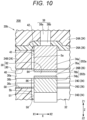
- test strip 200 in the present test, as illustrated in Fig. 9 , six each of a test strip 200 according to a comparative example, a test strip 10A according to a first example, a test strip 10A according to a second example, a test strip 10A according to a third example, a test strip 10B according to a fourth example, and a test strip 10B according to a fifth example were prepared.
- the test strip 200 includes a main body portion 20b, a first reagent piece 202a, and a second reagent piece 202b.
- the main body portion 20b is configured similarly to the main body portion 20 described above except that a second inner surface 51 and a first inner surface 41 are at the same position in the flow direction of blood (arrow X direction) in the flow path 30.
- the first reagent piece 202a and the second reagent piece 202b are configured similarly to the first reagent piece 22a and the second reagent piece 22b described above. Note, however, that the length of the second reagent piece 202b in the arrow X direction is the same as the length of the first reagent piece 202a in the arrow X direction.
- a first step portion 84 and a second step portion 86 are at the same position in the flow direction of blood in the flow path 30.
- a first gap Sa and a second gap Sb are positioned so as to face each other.
- the first to third examples are the test strip 10A according to the first embodiment.
- the offset length L1 is set to 0.35 mm.
- the offset length L1 is set to 0.85 mm.
- the offset length L1 is set to 0.2 mm.
- the fourth example and the fifth example are the test strips 10B according to the second embodiment.
- the offset length L2 is set to 0.35 mm.
- the offset length L2 is set to 0.85 mm.
- a blood circulation test (blood spreading evaluation) was performed on each of the test strips 200, 10A, and 10B. Specifically, in each of the test strips 200, 10A, and 10B, blood was introduced into the inlet portion 28 under an environment of 25°C, and it was confirmed whether or not the blood flowed to the downstream end of the reaction flow path 82 (whether or not the blood spread). Note that the hematocrit value (Ht) of the used blood is 60%.
- the blood spreading was evaluated in three stages of A, B, and C.
- the blood spreading evaluation was A when blood spread in all of the six test strips 200, 10A, and 10B.
- the blood spreading evaluation was B when blood spread in five of the six test strips 200, 10A, and 10B and blood did not spread in one.
- the blood spreading evaluation was C when blood spread in one of the six test strips 200, 10A, 10B and blood did not spread in five.
- the blood spreading evaluation of each of the first to third examples and the fifth example was A.
- the blood spreading evaluation of the fourth example was B.
- the blood spreading evaluation of the comparative example was C. From the above, the result was obtained that blood can be smoothly guided to the reaction flow path 82 by offsetting the first step portion 84 and the second step portion 86 from each other in the flow direction of blood in the flow path 30. In addition, a result was obtained that the blood spreading evaluation was good when the offset lengths L1 and L2 were 0.2 mm or more.
- test strips 10A and 10B the number of laminated layers of each of the film 24 and the adhesive layer 26 can be appropriately set.
- the test strips 10A and 10B may be configured such that the first reagent portion 76a and the second reagent portion 76b are directly applied to the inner surface of the flow path 30 without forming the first reagent placement hole 42 and the second reagent placement hole 50 in the main body portions 20 and 20a.
- the test strips 10A and 10B do not have the first gap Sa and the second gap Sb, but have the first step portion 84 and the second step portion 86.
- the present invention is not limited to the embodiments described above and may be modified in various manners without departing from the gist of the present invention.
- the above embodiment discloses a test strip (10A, 10B) having a flow path (30) for circulating a sample introduced from an inlet portion (28) by capillary force, the test strip including a first reagent portion (76a) and a second reagent portion (76b) provided in the flow path so as to face each other while being separated from each other, in which the flow path includes a first step portion (84) located at an upstream end of the flow path in the first reagent portion and a second step portion (86) located at an upstream end of the flow path in the second reagent portion, and the first step portion and the second step portion are offset from each other in a flow direction of the sample in the flow path.
- an offset length (L1, L2) between the first step portion and the second step portion may be 0.1 mm or more.
- the offset length may be 0.2 mm or more.
- the second reagent portion may be located below the first reagent portion, and the second step portion may be located upstream of the first step portion in the flow path.
- the second reagent portion may be located below the first reagent portion, and the second step portion may be located downstream of the first step portion in the flow path.
- a hydrophilic treatment portion (40, 58) may be provided on an inner surface of the flow path.
- the test strip may include a first reagent piece (22a, 120a) formed by providing the first reagent portion on a first support base (74a), a second reagent piece (22b, 120b) formed by providing the second reagent portion on a second support base (74b), a first reagent placement hole (42) in which the first reagent piece is placed, and a second reagent placement hole (50) in which the second reagent piece is placed.
- a first gap (Sa) may be formed between an inner surface (41) on the upstream side of the flow path in the first reagent placement hole and the first reagent piece
- a second gap (Sb) may be formed between an inner surface (51) on the upstream side of the flow path in the second reagent placement hole and the second reagent piece
- the first gap and the second gap may be offset so as not to face each other.
Landscapes
- Health & Medical Sciences (AREA)
- Life Sciences & Earth Sciences (AREA)
- Chemical & Material Sciences (AREA)
- Immunology (AREA)
- Engineering & Computer Science (AREA)
- Hematology (AREA)
- General Health & Medical Sciences (AREA)
- Physics & Mathematics (AREA)
- Molecular Biology (AREA)
- Analytical Chemistry (AREA)
- Biomedical Technology (AREA)
- Pathology (AREA)
- Biochemistry (AREA)
- General Physics & Mathematics (AREA)
- Urology & Nephrology (AREA)
- Biotechnology (AREA)
- Chemical Kinetics & Catalysis (AREA)
- Cell Biology (AREA)
- Microbiology (AREA)
- Food Science & Technology (AREA)
- Medicinal Chemistry (AREA)
- Plasma & Fusion (AREA)
- Clinical Laboratory Science (AREA)
- Dispersion Chemistry (AREA)
- Automatic Analysis And Handling Materials Therefor (AREA)
- Investigating Or Analysing Biological Materials (AREA)
Abstract
Description
- The present invention relates to a test strip.
-
WO 2021/192952 A discloses a test strip including a flow path for circulating a sample (blood) introduced from an inlet portion by capillary force. In the flow path, a reagent portion is arranged so as to form a lower surface of the flow path. An upper surface of the flow path is located above the reagent portion. - In the above-described test strip, when the sample introduced from the inlet portion reaches the reagent portion, the reagent component of the reagent portion diffuses toward the sample. In this case, since the diffusion distance of the reagent component is a distance from the reagent portion to the upper surface of the flow path, the diffusion time of the reagent component becomes relatively long. Therefore, the time (measurement standby time) from introduction of the sample into the inlet portion to completion of diffusion of the reagent component into the sample becomes long.
- An object of the present invention is to solve the above problem.
- One aspect of the present invention is a test strip having a flow path for circulating a sample introduced from an inlet portion by capillary force, the test strip including a first reagent portion and a second reagent portion provided in the flow path so as to face each other while being separated from each other. The flow path includes a first step portion located at an upstream end of the flow path in the first reagent portion and a second step portion located at an upstream end of the flow path in the second reagent portion, and the first step portion and the second step portion are offset from each other in a flow direction of the sample in the flow path.
- According to the present invention, the first reagent portion and the second reagent portion are provided in the flow path so as to face each other while being separated from each other. Therefore, when the sample introduced from the inlet portion arrives between the first reagent portion and the second reagent portion (reaction flow path), the reagent component of the first reagent portion and the reagent component of the second reagent portion are diffused into the sample. At this time, the diffusion distance of the reagent component is half the distance between the first reagent portion and the second reagent portion. Therefore, the diffusion time of the reagent component into the blood can be made relatively short.
- In addition, the first step portion and the second step portion are offset from each other in the flow direction of the sample in the flow path. In this case, the sample passes through one of the first step portion and the second step portion and then passes through the other of the first step portion and the second step portion. As a result, the flow path resistance can be dispersed in the flow direction of the sample in the flow path as compared with a case where the first step portion and the second step portion are provided at the same position in the flow direction of the sample in the flow path. Therefore, the sample introduced from the inlet portion can be smoothly guided to the reaction flow path. Therefore, the measurement standby time can be shortened.
-
-
Fig. 1 is a plan view illustrating an overall configuration of a component measurement system including a test strip according to a first embodiment of the present invention. -
Fig. 2 is a perspective view of the test strip ofFig. 1 . -
Fig. 3 is an exploded perspective view of the test strip ofFig. 2 . -
Fig. 4 is a longitudinal sectional view of the test strip ofFig. 2 . -
Fig. 5 is an enlarged cross-sectional view ofFig. 4 . -
Fig. 6 is a flowchart illustrating a method of manufacturing the test strip ofFig. 2 . -
Fig. 7 is a partially omitted cross-sectional explanatory view of the component measurement system ofFig. 1 . -
Fig. 8 is an enlarged cross-sectional view of a test strip according to a second embodiment of the present invention. -
Fig. 9 is an experimental result for explaining the effect of the test strip according to the present invention. -
Fig. 10 is an enlarged cross-sectional view of a test strip according to a comparative example. - As illustrated in
Fig. 1 , acomponent measurement system 12 according to a first embodiment of the present invention includes atest strip 10A capable of holding a sample, and acomponent measurement device 14 that measures the amount of an analyte contained in the sample by attaching thetest strip 10A. - A sample is introduced into the
test strip 10A. Thetest strip 10A is configured to be held at a detection target position in thecomponent measurement device 14 in a state in which a sample and a reagent are reacted with each other to cause coloring (colored state). On the other hand, thecomponent measurement device 14 optically detects a reaction product between the sample and the reagent at the detection target position of thetest strip 10A. Note that thetest strip 10A is also referred to as a chip, a sensor, or the like. The "sample" may be whole blood (blood) or separated plasma. In addition, the sample may be another body fluid or an aqueous solution containing an analyte. - Hereinafter, the component measurement system 12 (blood glucose level measurement system) that detects the amount of an analyte (glucose in this case) when the sample is blood will be representatively described. In particular, the
component measurement device 14 is configured as ablood glucose meter 16 that measures the blood glucose level by including ameasurement unit 18 that irradiates the detection target position with measurement light of a predetermined wavelength and detects the measurement light (transmitted light) transmitted through the detection target. - The
test strip 10A includes a reagent. The reagent contains a coloring reagent that is dissolved in the sample and reacts according to the amount of the analyte in the sample. Therefore, when the reagent and the analyte come into contact with each other, a color reaction occurs in which the coloring reagent develops color, and a color component (reaction product) is generated. - The reagent of the present embodiment specifically reacts with glucose. Examples of the reagent of the present embodiment include: a mixed reagent of (i) glucose oxidase (GOD), (ii) peroxidase (POD), (iii) 1-(4-sulfophenyl)-2,3-dimethyl-4-amino-5-pyrazolone, and (iv) N-ethyl-N-(2-hydroxy-3-sulfopropyl)-3,5-dimethylaniline sodium salt monohydrate (MAOS); and a mixed reagent of glucose dehydrogenase (GDH) and a tetrazolium salt. In addition, the reagent of the present embodiment contains a hemolytic agent and a hydrophilizing agent (sugar alcohol or the like). The reagent may further contain a buffer such as a phosphate buffer, a mediator, and an additive.
- The type and components of the reagent are not limited to the above. In the present embodiment, the
blood glucose meter 16 detects a mixture of a color component (reaction product) and a sample. In particular, when the detection target position is irradiated with measurement light having a predetermined wavelength and the measurement light (transmitted light) transmitted through the detection target is detected, the prepared mixed reagent solution is preferably directly applied to a predetermined position in thetest strip 10A without using a porous member or a carrier and dried. - In addition, the
component measurement system 12 is used as a personal use measurement system operated by a user (patient). For example, the user uses thetest strip 10A and theblood glucose meter 16 to measure his or her blood glucose level and control his or her blood glucose level. Note that thecomponent measurement system 12 may be used in a medical facility or the like as a device by which a medical worker measures a blood glucose level of a patient. - When the
test strip 10A is attached to theblood glucose meter 16, a part of thetest strip 10A protrudes to the outside of theblood glucose meter 16. Thetest strip 10A has an opening (inlet portion 28) on its end surface. The blood glucose level is measured by theblood glucose meter 16 by introducing blood into thetest strip 10A via theinlet portion 28. Thetest strip 10A is configured as a disposable component that is discarded after each measurement. - As illustrated in
Fig. 2 , thetest strip 10A includes amain body portion 20 having a test paper shape (flat plate shape), and afirst reagent piece 22a and asecond reagent piece 22b provided in themain body portion 20. Hereinafter, thefirst reagent piece 22a and thesecond reagent piece 22b may be simply referred to as "reagent piece 22" unless otherwise distinguished. - In the
main body portion 20, the insertion and detachment direction of theblood glucose meter 16 coincides with the longitudinal direction (arrow X direction) of themain body portion 20. One end portion (end portion in arrow X1 direction) of themain body portion 20 is exposed from theblood glucose meter 16 when themain body portion 20 is attached to the blood glucose meter 16 (state ofFig. 1 ). One end portion of themain body portion 20 is formed in a substantially semicircular shape when viewed from the thickness direction of the main body portion 20 (when viewed from arrow Z direction). - The other end portion (end portion in arrow X2 direction) of the
main body portion 20 is accommodated in theblood glucose meter 16 when themain body portion 20 is attached to the blood glucose meter 16 (state ofFig. 1 ). The other end portion (end portion in arrow X2 direction) of themain body portion 20 is formed in a rectangular shape as viewed from the thickness direction of the main body portion 20 (as viewed from arrow Z direction). That is, the outer shape of themain body portion 20 is a substantially rectangular shape in which one side (side in arrow X1 direction) bulges in an arc shape when viewed from the thickness direction. Note that when themain body portion 20 is attached to theblood glucose meter 16, a region including at least thefirst reagent piece 22a and thesecond reagent piece 22b from the other end (end in arrow X2 direction) of themain body portion 20 is accommodated in theblood glucose meter 16. - As illustrated in
Figs. 2 to 4 , themain body portion 20 is formed by sequentially laminating and integrating afirst film 24A, a firstadhesive layer 26A, asecond film 24B, a secondadhesive layer 26B, athird film 24C, the thirdadhesive layer 26C, thefourth film 24D, the fourthadhesive layer 26D, and thefifth film 24E from the upper direction (arrow Z1 direction) toward the lower direction (arrow Z2 direction) inFig. 3 . Hereinafter, thefirst film 24A, thesecond film 24B, thethird film 24C, thefourth film 24D, and thefifth film 24E may be simply referred to as "film 24" unless otherwise distinguished. In addition, the firstadhesive layer 26A, the secondadhesive layer 26B, the thirdadhesive layer 26C, and the fourthadhesive layer 26D may be simply referred to as "adhesive layer 26" unless otherwise distinguished. Each of thefilm 24 and theadhesive layer 26 exemplified here does not refer to only those composed of a single member. Each of thefilm 24 and theadhesive layer 26 may be a member made of a plurality of base materials. - The outer edge of each
film 24 and eachadhesive layer 26 is formed in a substantially rectangular shape having an arc at one end portion when viewed from the arrow Z direction. A space portion is appropriately cut out in eachfilm 24 and eachadhesive layer 26. - The
main body portion 20 is provided with theinlet portion 28 for taking blood into themain body portion 20, aflow path 30 that guides the blood taken in through theinlet portion 28 onto thereagent piece 22, and abuffer space 32 communicating with theflow path 30. - The
inlet portion 28 is provided at one end portion (end portion in arrow X1 direction) of themain body portion 20, which is formed in an arc shape in plan view in the arrow Z direction. One end of theinlet portion 28 in the arrow Z1 direction is open, and the other end in the arrow Z2 direction is covered with thefourth film 24D. - One end (arrow X1 direction) of the
flow path 30 is open to theinlet portion 28. The length of theinlet portion 28 in the width direction is longer than the length of theflow path 30 in the width direction. Theflow path 30 transfers blood by capillary force. Theinlet portion 28, theflow path 30, and thebuffer space 32 are formed by laminating space portions formed in thefilm 24 and theadhesive layer 26. - As illustrated in
Figs. 3 and4 , thefirst film 24A is arranged at an end in the arrow Z1 direction. Thefirst film 24A is made of a light shielding member (e.g., black film).First film 24A is made of, for example, polyethylene terephthalate (PET) to which a black pigment is added. That is, thefirst film 24A includes alight shielding portion 36 that shields a part of the measurement light. The thickness of thefirst film 24A is preferably set to, for example, 50 um or more and 300 um or less, and more preferably set to 150 um or more and 200 um or less. - A
first cutout portion 28a and a first through-hole 38a are formed in thefirst film 24A. Thefirst cutout portion 28a forms a part of theinlet portion 28. Thefirst cutout portion 28a is formed at an end portion of the first film - 24A in the arrow X1 direction. The
first cutout portion 28a is formed in a rectangular shape with one side opened in plan view in the arrow Z direction. - The first through-
hole 38a is independently provided at a position away from thefirst cutout portion 28a by a predetermined distance in the arrow X2 direction. The first through-hole 38a penetrates thefirst film 24A in the arrow Z direction. The first through-hole 38a is located substantially at the center in the width direction (arrow Y direction) of thefirst film 24A. The first through-hole 38a is formed in a circular shape. - The first
adhesive layer 26A is laminated on thefirst film 24A in the arrow Z2 direction. The firstadhesive layer 26A is made of, for example, an acrylic adhesive. The firstadhesive layer 26A is a double-sided adhesive tape (adhesive sheet) having an adhesive function on both surfaces. The thickness of the firstadhesive layer 26A is preferably set to 15 um or more and 35 um or less, and more preferably set to about 25 µm. - The first
adhesive layer 26A is formed in the same shape and the same size as thefirst film 24A in plan view in the arrow Z direction. Specifically, asecond cutout portion 28b and a second through-hole 38b are formed in the firstadhesive layer 26A. Thesecond cutout portion 28b forms a part of theinlet portion 28. Thesecond cutout portion 28b communicates with thefirst cutout portion 28a in the arrow Z2 direction. Thesecond cutout portion 28b is formed in the same size and the same shape as thefirst cutout portion 28a in plan view in the arrow Z direction. - The second through-
hole 38b penetrates the firstadhesive layer 26A in the arrow Z direction. The second through-hole 38b communicates with the first through-hole 38a in the arrow Z2 direction. The second through-hole 38b is formed in the same size and the same shape as the first through-hole 38a in plan view in the arrow Z direction. - The first through-
hole 38a and the second through-hole 38b communicate with each other to form afirst opening 38 for allowing measurement light to pass in the thickness direction of thetest strip 10A. By forming thefirst opening 38 in thefirst film 24A and the firstadhesive layer 26A in this manner, an amount of measurement light necessary for optical detection of a reaction product (measurement target) between a sample and a reagent can reach the detection target through thefirst opening 38. In addition, since thefirst film 24A is made of a light shielding member, measurement light can only pass through thefirst opening 38. As a result, stray light that affects detection accuracy can be reduced. - The
first film 24A and the firstadhesive layer 26A may be provided with a transparent portion (light guide portion) through which measurement light can pass instead of the first opening 38 (first through-hole 38a and second through-hole 38b). - The
second film 24B is laminated on the firstadhesive layer 26A in the arrow Z2 direction. Thesecond film 24B is made of, for example, polyester (PE). A first hydrophilic treatment portion 40 (hydrophilic coating) is provided on the surface of thesecond film 24B in the arrow Z2 direction. The contact angle of the firsthydrophilic treatment portion 40 is preferably set to less than 20°. The thickness of thesecond film 24B is preferably set to 90 um or more and 110 um or less, and more preferably set to about 100 um. - The
second film 24B is a first cover layer that covers theflow path 30 from the arrow Z1 direction. In thesecond film 24B, athird cutout portion 28c, afirst buffer hole 32a, and a firstreagent placement hole 42 are formed. Thethird cutout portion 28c forms a part of theinlet portion 28. Thethird cutout portion 28c is formed at an end portion of thesecond film 24B in the X1 direction. Thethird cutout portion 28c communicates with thesecond cutout portion 28b in the arrow Z2 direction. Thethird cutout portion 28c is formed in the same size and the same shape as the first andsecond cutout portions - The
first buffer hole 32a forms a part of thebuffer space 32. Thefirst buffer hole 32a is a rectangular through-hole penetrating thesecond film 24B in the thickness direction. Thefirst buffer hole 32a is provided at a position away from thethird cutout portion 28c by a predetermined distance in the arrow X2 direction. Thefirst buffer hole 32a is located substantially at the center in the width direction of thesecond film 24B. - The first
reagent placement hole 42 is a space for placing thefirst reagent piece 22a, and is provided between thethird cutout portion 28c and thefirst buffer hole 32a. The firstreagent placement hole 42 penetrates thesecond film 24B in the thickness direction and extends in a rectangular shape over the entire width (entire length in arrow Y direction) of thesecond film 24B. The firstreagent placement hole 42 communicates with thefirst buffer hole 32a. - The
second film 24B is divided into afirst member 43a and asecond member 43b by the firstreagent placement hole 42. Thefirst member 43a is located in the arrow X1 direction of thesecond member 43b. Thethird cutout portion 28c is formed in thefirst member 43a. - A
wall portion 44 of thesecond film 24B between thethird cutout portion 28c and the firstreagent placement hole 42 covers theflow path 30 described later from the arrow Z1 direction (seeFig. 4 ). In thesecond film 24B, it is possible to provide the firsthydrophilic treatment portion 40 only on the surface of thewall portion 44 in the arrow Z2 direction and not provide the firsthydrophilic treatment portion 40 in parts other than thewall portion 44. - The second
adhesive layer 26B is laminated on thesecond film 24B in the arrow Z2 direction. The secondadhesive layer 26B is made of, for example, an acrylic adhesive. The secondadhesive layer 26B is a double-sided adhesive tape (adhesive sheet) having an adhesive function on both surfaces. The secondadhesive layer 26B may have adhesive layers on both surfaces of a film-like base material. The thickness of the secondadhesive layer 26B is preferably set to 35 um or more and 55 um or less, and more preferably set to about 45 µm. - The second
adhesive layer 26B is a first spacer layer for forming theflow path 30. In the secondadhesive layer 26B, afourth cutout portion 28d, a firstflow path groove 30a, and asecond buffer hole 32b are formed. Thefourth cutout portion 28d forms a part of theinlet portion 28. Thefourth cutout portion 28d is formed at an end portion of the secondadhesive layer 26B in the arrow X1 direction. Thefourth cutout portion 28d communicates with thethird cutout portion 28c in the arrow Z2 direction. Thefourth cutout portion 28d is formed in the same size and the same shape as the first tothird cutout portions 28a to 28c in plan view in the arrow Z direction. - The first flow path groove 30a forms a part of the
flow path 30. The firstflow path groove 30a linearly extends along the longitudinal direction (arrow X direction) of the secondadhesive layer 26B. The firstflow path groove 30a penetrates the secondadhesive layer 26B in the thickness direction. The firstflow path groove 30a is located substantially at the center in the width direction of the secondadhesive layer 26B. - One end (end in arrow X1 direction and initial end) of the first
flow path groove 30a communicates with thefourth cutout portion 28d. The other end (end in arrow X2 direction and terminal end) of the firstflow path groove 30a communicates with thesecond buffer hole 32b. That is, thefourth cutout portion 28d, the firstflow path groove 30a, and thesecond buffer hole 32b form one continuous space. - The first
flow path groove 30a is formed to be narrower than thefourth cutout portion 28d. The firstflow path groove 30a is covered with thewall portion 44 of thesecond film 24B from the arrow Z1 direction (seeFig. 4 ). That is, thewall portion 44 of thesecond film 24B liquid-tightly blocks the first flow path groove 30a from thefirst opening 38. Thewall portion 44 of thesecond film 24B is a top surface of theflow path 30 in the arrow Z1 direction. - The
second buffer hole 32b forms a part of thebuffer space 32. Thesecond buffer hole 32b is a rectangular through-hole penetrating the secondadhesive layer 26B in the thickness direction. Thesecond buffer hole 32b is formed at a position facing thefirst buffer hole 32a. That is, thesecond buffer hole 32b communicates with thefirst buffer hole 32a in the arrow Z2 direction. Thesecond buffer hole 32b is formed in the same size and the same shape as thefirst buffer hole 32a in plan view in the arrow Z direction. - The
third film 24C is laminated on the secondadhesive layer 26B in the arrow Z2 direction. Thethird film 24C is made of, for example, polyethylene terephthalate (PET). The thickness of thethird film 24C is preferably set to 15 um or more and 35 um or less, and more preferably set to about 25 um. That is, the thickness (length in arrow Z direction) of thethird film 24C is thinner than the thickness of the secondadhesive layer 26B. - The
third film 24C is an intermediate spacer layer for forming theflow path 30. In thethird film 24C, afifth cutout portion 28e, an intermediateflow path groove 30b, afirst placement hole 50a, and athird buffer hole 32c are formed. Thefifth cutout portion 28e forms a part of theinlet portion 28. Thefifth cutout portion 28e is formed at an end portion of thethird film 24C in the arrow X1 direction. Thefifth cutout portion 28e communicates with thefourth cutout portion 28d in the arrow Z2 direction. Thefifth cutout portion 28e is formed in the same shape and the same size as the first tofourth cutout portions 28a to 28d in plan view in the arrow Z direction. - The intermediate
flow path groove 30b forms a part of theflow path 30. The intermediateflow path groove 30b extends linearly along the longitudinal direction of thethird film 24C. The intermediateflow path groove 30b penetrates thethird film 24C in the thickness direction. The intermediateflow path groove 30b is located substantially at the center in the width direction of thethird film 24C. One end (end in arrow X1 direction and initial end) of the intermediateflow path groove 30b communicates with thefifth cutout portion 28e. The other end (end in arrow X2 direction and terminal end) of the intermediateflow path groove 30b is connected to thefirst placement hole 50a. - The intermediate
flow path groove 30b is formed to be narrower than thefifth cutout portion 28e. The intermediateflow path groove 30b is formed at a position facing the firstflow path groove 30a. That is, the intermediateflow path groove 30b communicates with the firstflow path groove 30a in the arrow Z2 direction. The width of the intermediateflow path groove 30b along the arrow Y direction is the same as the width of the firstflow path groove 30a along the arrow Y direction. In the arrow X direction, the entire length of the intermediateflow path groove 30b is shorter than the entire length of the firstflow path groove 30a (seeFig. 4 ). The length of the firstflow path groove 30a along the arrow Z direction is longer than the length of the intermediateflow path groove 30b along the arrow Z direction. - The
first placement hole 50a forms a part of a secondreagent placement hole 50 for placing thesecond reagent piece 22b. Thefirst placement hole 50a is provided between the intermediateflow path groove 30b and thethird buffer hole 32c. Thefirst placement hole 50a penetrates thethird film 24C in the thickness direction and extends in a rectangular shape over the entire width (entire length in arrow Y direction) of thethird film 24C. Thefirst placement hole 50a is provided at an end of the intermediateflow path groove 30b in the arrow X2 direction. - The
third film 24C is divided into afirst member 52a, asecond member 52b, and athird member 52c by thefifth cutout portion 28e, the intermediateflow path groove 30b, and thefirst placement hole 50a. Thefirst member 52a and thesecond member 52b are arranged on both sides of the intermediateflow path groove 30b in the arrow Y direction. Thethird member 52c is arranged in the arrow X2 direction of thefirst member 52a and thesecond member 52b with thefirst placement hole 50a interposed therebetween. - The
third buffer hole 32c forms a part of thebuffer space 32. Thethird buffer hole 32c is a rectangular through-hole penetrating thethird film 24C in the thickness direction. Thethird buffer hole 32c is formed at a position facing thesecond buffer hole 32b. That is, thethird buffer hole 32c communicates with thesecond buffer hole 32b in the arrow Z2 direction. Thethird buffer hole 32c is formed in the same shape and the same size as the first andsecond buffer holes - The third
adhesive layer 26C is laminated on thethird film 24C in the arrow Z2 direction. The thirdadhesive layer 26C is made of, for example, an acrylic adhesive. The thirdadhesive layer 26C is a double-sided adhesive tape (adhesive sheet) having an adhesive function on both surfaces. The thickness of the thirdadhesive layer 26C is preferably set to 15 um or more and 35 um or less, and more preferably set to about 25 um. That is, the thickness of the thirdadhesive layer 26C is thinner than the thickness of the secondadhesive layer 26B. Additionally, the thickness of the thirdadhesive layer 26C is substantially the same as the thickness of thethird film 24C. - The third
adhesive layer 26C is a second spacer layer for forming theflow path 30. The thirdadhesive layer 26C is formed in the same shape and the same size as thethird film 24C in plan view in the arrow Z direction. Specifically, in the thirdadhesive layer 26C, asixth cutout portion 28f, a secondflow path groove 30c, asecond placement hole 50b, and afourth buffer hole 32d are formed. Thesixth cutout portion 28f forms a part of theinlet portion 28. Thesixth cutout portion 28f communicates with thefifth cutout portion 28e in the arrow Z2 direction. Thesixth cutout portion 28f is formed in the same shape and the same size as the first tofifth cutout portions 28a to 28e in plan view in the arrow Z direction. - The second
flow path groove 30c forms a part of theflow path 30. The secondflow path groove 30c extends linearly along the longitudinal direction of the thirdadhesive layer 26C. The secondflow path groove 30c penetrates the thirdadhesive layer 26C in the thickness direction. The secondflow path groove 30c is located substantially at the center in the width direction of the thirdadhesive layer 26C. One end (end in arrow X1 direction and initial end) of the secondflow path groove 30c communicates with thesixth cutout portion 28f. The other end (end in arrow X2 direction and terminal end) of the secondflow path groove 30c is connected to thesecond placement hole 50b. - The second
flow path groove 30c is formed to be narrower than thesixth cutout portion 28f. The secondflow path groove 30c is formed at a position facing the intermediateflow path groove 30b. That is, the secondflow path groove 30c communicates with the intermediateflow path groove 30b in the arrow Z2 direction. The width of the secondflow path groove 30c along the arrow Y direction is the same as the width of the intermediateflow path groove 30b along the arrow Y direction. In the arrow X direction, the entire length of the secondflow path groove 30c is equal to the entire length of intermediateflow path groove 30b (seeFig. 4 ). The length of the firstflow path groove 30a along the arrow X direction is longer than the length of the secondflow path groove 30c along the arrow X direction. The length of the secondflow path groove 30c along the arrow X direction is substantially the same as the length of the intermediateflow path groove 30b along the arrow X direction. - The
second placement hole 50b forms a part of the secondreagent placement hole 50 for placing thesecond reagent piece 22b. Thesecond placement hole 50b is provided between the secondflow path groove 30c and thefourth buffer hole 32d. Thesecond placement hole 50b communicates with thefirst placement hole 50a in the arrow Z2 direction. - The third
adhesive layer 26C is divided into afirst member 56a, asecond member 56b, and athird member 56c by thesixth cutout portion 28f, the secondflow path groove 30c, and thesecond placement hole 50b. Thefirst member 56a is located in the arrow Z2 direction of thefirst member 52a of thethird film 24C. Thesecond member 56b is located in the arrow Z2 direction of thesecond member 52b of thethird film 24C. Thethird member 56c is located in the arrow Z2 direction of thethird member 52c of thethird film 24C. - The
fourth buffer hole 32d forms a part of thebuffer space 32. Thefourth buffer hole 32d communicates with thethird buffer hole 32c in the arrow Z2 direction. Thefourth buffer hole 32d is formed in the same shape and the same size as the first tothird buffer holes 32a to 32c in plan view in the arrow Z direction. - The
fourth film 24D is laminated on the thirdadhesive layer 26C in the arrow Z2 direction. Thefourth film 24D is made of, for example, polyester (PE). A second hydrophilic treatment portion 58 (hydrophilic coating) is provided on the surface of thefourth film 24D in the arrow Z1 direction. The contact angle of the secondhydrophilic treatment portion 58 is preferably set to less than 20°. The thickness of thefourth film 24D is preferably set to 80 um or more and 120 um or less, more preferably set to 90 um or more and 110 um or less, and still more preferably set to about 100 µm. - The
fourth film 24D is a second cover layer covering theflow path 30 from the arrow Z2 direction. Athird placement hole 50c and afifth buffer hole 32e are formed in thefourth film 24D. Thethird placement hole 50c forms a part of the secondreagent placement hole 50 for placing thesecond reagent piece 22b. Thethird placement hole 50c is formed at a position facing thesecond placement hole 50b. Thethird placement hole 50c is formed in the same shape and the same size as thefirst placement hole 50a and thesecond placement hole 50b when viewed from the arrow Z direction. Thethird placement hole 50c penetrates thefourth film 24D in the thickness direction and extends over the entire width (entire length in arrow Y direction) of thefourth film 24D. - The
fourth film 24D is divided into afirst member 64a and asecond member 64b by thethird placement hole 50c. Thefirst member 64a is located in the arrow X1 direction of thesecond member 64b. Thefirst member 64a liquid-tightly covers thesixth cutout portion 28f and the secondflow path groove 30c from the arrow Z2 direction (seeFig. 4 ). An end portion of thefirst member 64a in the arrow X1 direction is formed in a semicircular shape. - The
fifth buffer hole 32e forms a part of thebuffer space 32. Thefifth buffer hole 32e is a rectangular through-hole penetrating thefourth film 24D in the thickness direction. Thefifth buffer hole 32e is formed at a position facing thefourth buffer hole 32d. That is, thefifth buffer hole 32e communicates with thefourth buffer hole 32d in the arrow Z2 direction. Thefifth buffer hole 32e is formed in the same shape and the same size as the first tofourth buffer holes 32a to 32d in plan view in the arrow Z direction. In thefourth film 24D, it is possible to provide the secondhydrophilic treatment portion 58 only on the surface of thefirst member 64a in the arrow Z1 direction and not provide the secondhydrophilic treatment portion 58 in parts other than thefirst member 64a (second member 64b). - The fourth
adhesive layer 26D is laminated on thefourth film 24D in the arrow Z2 direction. The fourthadhesive layer 26D is made of, for example, an acrylic adhesive. The fourthadhesive layer 26D is a double-sided adhesive tape (adhesive sheet) having an adhesive function on both surfaces. The thickness of the fourthadhesive layer 26D is preferably set to 15 um or more and 35 um or less, and more preferably set to about 25 µm. - The fourth
adhesive layer 26D is formed in the same shape and the same size as thefourth film 24D in plan view in the arrow Z direction. Specifically, afourth placement hole 50d and asixth buffer hole 32f are formed in the fourthadhesive layer 26D. Thefourth placement hole 50d forms a part of the secondreagent placement hole 50 for placing thesecond reagent piece 22b. Thefourth placement hole 50d communicates with thethird placement hole 50c in the arrow Z2 direction. Thefourth placement hole 50d is formed in the same shape and the same size as thethird placement hole 50c in plan view in the arrow Z direction. Thefirst placement hole 50a, thesecond placement hole 50b, thethird placement hole 50c, and thefourth placement hole 50d communicate with each other to form one secondreagent placement hole 50. - The fourth
adhesive layer 26D is divided into afirst member 66a and asecond member 66b by thefourth placement hole 50d. Thefirst member 66a is located in the arrow Z2 direction of thefirst member 64a of thefourth film 24D. Thesecond member 66b is located in the arrow Z2 direction of thesecond member 64b of thefourth film 24D. - The
sixth buffer hole 32f forms a part of thebuffer space 32. Thesixth buffer hole 32f communicates with thefifth buffer hole 32e in the arrow Z2 direction. Thesixth buffer hole 32f is formed in the same shape and the same size as the first tofifth buffer holes 32a to 32e in plan view in the arrow Z direction. - The
fifth film 24E may be further laminated on the fourthadhesive layer 26D in the arrow Z2 direction. Thefifth film 24E is arranged at the end in the thickness direction (end in arrow Z2 direction) of thetest strip 10A. Thefifth film 24E forms one surface of thetest strip 10A. Thefifth film 24E liquid-tightly covers thesixth buffer hole 32f from the arrow Z2 direction (seeFig. 4 ). Asecond opening 68 is formed in thefifth film 24E. - The
second opening 68 is a circular through-hole that transmits measurement light in the thickness direction of thetest strip 10A. Thesecond opening 68 is positioned in the arrow Z2 direction of thefirst opening 38. The diameter of thesecond opening 68 is larger than the diameter of thefirst opening 38. In other words, thesecond opening 68 is provided such that the entirefirst opening 38 is located inside thesecond opening 68 when viewed from the arrow Z direction. Note that thefifth film 24E may be provided with a transparent portion (light guide portion) through which measurement light can pass instead of thesecond opening 68. - In the
main body portion 20 configured as described above, theinlet portion 28 is formed by the first tosixth cutout portions 28a to 28f. Theflow path 30 is formed by the firstflow path groove 30a, the intermediateflow path groove 30b, and the secondflow path groove 30c. Thebuffer space 32 is formed by the first tosixth buffer holes 32a to 32f. - In
Fig. 4 , the initial end of theflow path 30 communicates with theinlet portion 28. The terminal end of the flow path 30 (terminal end of firstflow path groove 30a) communicates with thebuffer space 32. Thefirst reagent piece 22a and thesecond reagent piece 22b for analyte detection are placed at any position between the initial end and the terminal end of theflow path 30. That is, thebuffer space 32 exists downstream of thefirst reagent piece 22a and thesecond reagent piece 22b in theflow path 30. - As illustrated in
Figs. 3 to 5 , thefirst reagent piece 22a includes afirst support base 74a and afirst reagent portion 76a provided on thefirst support base 74a. In plan view in the arrow Z direction, thefirst support base 74a is formed in a rectangular shape. Thefirst reagent portion 76a is located substantially at the center in the longitudinal direction (arrow Y direction) of thefirst support base 74a. The surface of thefirst support base 74a in the arrow Z1 direction is bonded to the surface of the firstadhesive layer 26A in the arrow Z2 direction. The surfaces of thefirst support base 74a in the arrow Z2 direction on both sides of thefirst reagent portion 76a in the longitudinal direction are bonded to the surface of the secondadhesive layer 26B in the arrow Z1 direction such that thefirst reagent portion 76a is positioned in the firstflow path groove 30a. In this case, a first gap Sa is formed between an inner surface (first inner surface 41) of the firstreagent placement hole 42 on the upstream side of theflow path 30 and thefirst support base 74a. The length of the first gap Sa along the arrow X direction is more than 0 mm and 0.1 mm or less. The arrow Z1 side of the first gap Sa is sealed by the firstadhesive layer 26A in order to prevent blood leakage to thefirst opening 38. At this time, the firstadhesive layer 26A adheres thefirst film 24A and thefirst support base 74a in a slightly compressed state. The firstadhesive layer 26A can prevent blood from reaching thefirst opening 38 even if blood leaks into the first gap Sa. - The
first support base 74a extends long in the lateral direction (width direction, i.e., arrow Y direction) of thetest strip 10A. That is, thefirst support base 74a is formed in a rectangular shape where the length of thefirst support base 74a in the lateral direction of thetest strip 10A is shorter than the length of thefirst support base 74a in the longitudinal direction (arrow X direction) of thetest strip 10A. As thefirst support base 74a, a film material having transparency can be used. - The
first reagent portion 76a is obtained by supporting a reagent that reacts with a sample on at least a part of theflow path 30. Thefirst reagent portion 76a is applied to thefirst support base 74a without blocking theflow path 30. Various polymers and coating compositions may be further arranged on thefirst support base 74a depending on the properties of the reagent and the measurement system. - In plan view in the arrow Z direction, the
first reagent portion 76a is formed in a quadrangular shape (seeFig. 3 ). As illustrated inFig. 5 , in the arrow X direction, the length of thefirst reagent portion 76a is the same as the length of thefirst support base 74a. The length of thefirst reagent portion 76a in the arrow X direction is set to, for example, 1.0 mm or more and 2.0 mm or less. - The
second reagent piece 22b includes asecond support base 74b and asecond reagent portion 76b provided on thesecond support base 74b. Thesecond reagent piece 22b is basically configured similarly to thefirst reagent piece 22a. Note, however, that the length of thesecond reagent piece 22b in the arrow X direction is longer than the length of thefirst reagent piece 22a in the arrow X direction. Thesecond reagent portion 76b is located substantially at the center in the longitudinal direction (arrow Y direction) of thesecond support base 74b. Both sides of thesecond reagent portion 76b in the longitudinal direction of thesecond support base 74b are bonded to the surface of the secondadhesive layer 26B in the arrow Z2 direction such that thesecond reagent portion 76b is positioned in the firstflow path groove 30a. In this case, a second gap Sb is formed between an inner surface (second inner surface 51) of the secondreagent placement hole 50 on the upstream side of theflow path 30 and thesecond support base 74b. The length of the second gap Sb in the arrow X direction is more than 0 mm and 0.1 mm or less. - The
second reagent portion 76b is configured similarly to thefirst reagent portion 76a. Therefore, detailed description of the configuration of thesecond reagent portion 76b is omitted. Note that the reagent components contained in thefirst reagent portion 76a and thesecond reagent portion 76b may be the same or different from each other. Thesecond reagent portion 76b is formed in a quadrangular shape (seeFig. 3 ). In the arrow X direction, the length of thesecond reagent portion 76b is the same as the length of thesecond support base 74b. The length of thesecond reagent portion 76b in the arrow X direction is set to, for example, 1.0 mm or more and 2.0 mm or less. - The length of the
second reagent portion 76b in the arrow X direction is longer than the length of thefirst reagent portion 76a in the arrow X direction. Thefirst reagent portion 76a and thesecond reagent portion 76b are arranged in theflow path 30 so as to face each other in the vertical direction. In the flow direction of blood in theflow path 30, the upstream end of thesecond reagent portion 76b is offset in the arrow X1 direction from the upstream end of thefirst reagent portion 76a. Note that in the flow direction of blood in theflow path 30, the downstream end of thesecond reagent portion 76b is at the same position as the downstream end of thefirst reagent portion 76a. Note, however, that the downstream end of thesecond reagent portion 76b and the downstream end of thefirst reagent portion 76a may be arranged at the same position or may be offset from each other in the flow direction of blood (arrow X direction) in theflow path 30. - In the
test strip 10A configured as described above, theflow path 30 includes anintroduction flow path 80 and areaction flow path 82. Theintroduction flow path 80 guides blood (sample) introduced into theinlet portion 28 to thereaction flow path 82. Theintroduction flow path 80 extends from theinlet portion 28 to thefirst reagent portion 76a. Thereaction flow path 82 is a portion between thefirst reagent portion 76a and thesecond reagent portion 76b. Note that thesecond reagent portion 76b is arranged below thefirst reagent portion 76a. The reaction flow path 82 (first reagent portion 76a andsecond reagent portion 76b) overlaps thefirst opening 38 when viewed from the arrow Z direction (seeFig. 4 ). Therefore, measurement light of theblood glucose meter 16 is emitted toward thereaction flow path 82. - The length of the
introduction flow path 80 in the arrow Z direction (first flow path height H1) is longer (higher) than the length of thereaction flow path 82 in the arrow Z direction (second flow path height H2). The second flow path height H2 is preferably set to 20 um or more and 40 um or less, and is set to 30 µm, for example. Note, however, that the second flow path height H2 can be appropriately set. - The
flow path 30 includes afirst step portion 84 and asecond step portion 86. Thefirst step portion 84 is located at the upstream end (end in arrow X1 direction) of theflow path 30 in thefirst reagent portion 76a. Thesecond step portion 86 is located at the upstream end (end in arrow X1 direction) of theflow path 30 in thesecond reagent portion 76b. The height from the bottom surface (second hydrophilic treatment portion 58) of theflow path 30 to the upper surface of thesecond reagent portion 76b (height of second step portion 86) is higher than the height from the upper surface (first hydrophilic treatment portion 40) of theflow path 30 to the lower surface of thefirst reagent portion 76a (height of first step portion 84). In the flow direction of blood in theflow path 30, thefirst step portion 84 and thesecond step portion 86 are offset from each other. Specifically, thesecond step portion 86 is located upstream of thefirst step portion 84 in theflow path 30. An offset length L1 between thefirst step portion 84 and thesecond step portion 86 is 0.1 mm or more. The offset length L1 is preferably 0.2 mm or more and 0.8 mm or less. - The
second step portion 86 is located upstream (arrow X1 direction) of the first gap Sa in theflow path 30. Therefore, thesecond reagent portion 76b covers the first gap Sa from the arrow Z2 direction. Additionally, the firsthydrophilic treatment portion 40 covers the second gap Sb from the arrow Z1 direction. In the flow direction of blood in theflow path 30, the first gap Sa and the second gap Sb are offset so as not to face each other across theflow path 30. In other words, the second gap Sb is offset to the upstream side of theflow path 30 with respect to the first gap Sa. Moreover, the secondinner surface 51 is located upstream of the firstinner surface 41 in theflow path 30. - The plurality of
films 24 is not limited to the examples made of the above-described materials. The plurality offilms 24 can be made of resin materials such as polyethylene terephthalate (PET), polymethyl methacrylate (PMMA), polyester, polycarbonate, polystyrene, polypropylene, acrylonitrile-butadiene-styrene copolymer (ABS), cycloolefin polymer (COP), and cyclic olefin copolymer (COC). In a case where thecomponent measurement device 14 is of a type that detects measurement light (transmitted light) transmitted through the detection target, the path of the measurement light is made of a material having transparency. As thefilm 24, a pigment may be mixed depending on the purpose, and when thefilm 24 is used as a light shielding member, a resin material containing carbon black can be used. Note that based on the measurement method of JIS K7605;1976 (abolished standard), the light shielding ratio of the light shielding member is preferably 90% or more, and a black film member having a light shielding ratio of 99% or more can be suitably used. - In the
test strip 10A, theflow path 30 is not limited to the example formed in three layers of the first spacer layer, the intermediate spacer layer, and the second spacer layer, and may be formed over four or more layers. - The above-described
test strip 10A is manufactured by cutting and laminating a plurality offilms 24 subjected to an appropriate surface treatment and a plurality of adhesive sheets. Specifically, as illustrated inFig. 6 , the method of manufacturing thetest strip 10A includes a processing step, a first lamination step, a first reagent piece placement step, a second lamination step, a second reagent piece placement step, and a third lamination step. - In the processing step (step S1), the first to
fifth films 24A to 24E are formed by processing (punching) thefilm 24 with a cutting tool, and the first to fourthadhesive layers 26A to 26D are formed by processing (punching) the adhesive sheet with the cutting tool. - In the first lamination step (step S2), the
first film 24A, the firstadhesive layer 26A, and thesecond film 24B are laminated and bonded in this order. - In the first reagent piece placement step (step S3), the
first reagent piece 22a is placed in the firstreagent placement hole 42. At this time, both sides of thefirst reagent portion 76a in thefirst support base 74a are bonded to the surface of the firstadhesive layer 26A in the arrow Z2 direction. As a result, thefirst reagent piece 22a is fixed to the firstadhesive layer 26A. - In the second lamination step (step S4), the second
adhesive layer 26B, thethird film 24C, the thirdadhesive layer 26C, thefourth film 24D, and the fourthadhesive layer 26D are bonded to thesecond film 24B while being laminated in this order. - In the second reagent piece placement step (step S5), the
second reagent piece 22b is inserted from thefourth placement hole 50d into the secondreagent placement hole 50. At this time, both sides of thesecond reagent portion 76b in thesecond support base 74b are bonded to the surface of the secondadhesive layer 26B in the arrow Z2 direction. As a result, thesecond reagent piece 22b is fixed to the secondadhesive layer 26B. - In the third lamination step (step S6), the
fifth film 24E is bonded to the fourthadhesive layer 26D. Thus, thetest strip 10A is manufactured. - The method of manufacturing the
test strip 10A is not limited to the method described above. - Next, the
blood glucose meter 16 to which thetest strip 10A is attached will be described. As illustrated inFig. 1 , theblood glucose meter 16 is configured as a reusable type capable of repeatedly measuring the blood glucose level. Ahousing 90 of theblood glucose meter 16 has abox portion 94 having a size that allows the user to easily grip and operate the blood glucose meter and accommodating acontrol unit 92 of theblood glucose meter 16 therein, and a cylindricalphotometric unit 96 protruding from thebox portion 94 and accommodating themeasurement unit 18 of the optical system therein. - A
power button 98, anoperation button 100, and adisplay 102 are provided on an upper surface of thebox portion 94. Aneject lever 104 as an operation unit for detaching thetest strip 10A after use is provided on an upper surface of thephotometric unit 96. Theeject lever 104 is provided to be movable along the extending direction of thephotometric unit 96, and is connected to an eject pin 106 (seeFig. 7 ) provided in thephotometric unit 96. - As illustrated in
Fig. 7 , thephotometric unit 96 is provided with aninsertion hole 108 into which thetest strip 10A is inserted. Themeasurement unit 18 optically detects glucose in blood. Themeasurement unit 18 includes alight emitting unit 110 and alight receiving unit 112. Thelight emitting unit 110 and thelight receiving unit 112 are arranged to face each other with theinsertion hole 108 interposed therebetween. - As the
light emitting unit 110, an LED, an organic EL, a laser diode, or the like is used. In a state where thetest strip 10A is attached to theinsertion hole 108, thelight emitting unit 110 emits light having a predetermined wavelength toward thefirst opening 38 of thetest strip 10A. As thelight receiving unit 112, for example, a photodiode is used. Thelight receiving unit 112 receives the light transmitted through thetest strip 10A (first reagent portion 76a andsecond reagent portion 76b). - The
control unit 92 of theblood glucose meter 16 includes a control circuit (computer) having a converter, a processor, a memory, and an input/output interface (not illustrated). For example, thecontrol unit 92 drives themeasurement unit 18 under the operation of the user to calculate the blood glucose level based on a signal corresponding to the amount (or concentration) of glucose in the blood. The calculated blood glucose level is displayed on thedisplay 102. - Next, the measurement of the blood glucose level using the
test strip 10A according to the present embodiment will be described. - As illustrated in
Fig. 7 , the user inserts thetest strip 10A into theinsertion hole 108 of theblood glucose meter 16, and positions thefirst reagent portion 76a and thesecond reagent portion 76b of thetest strip 10A between thelight emitting unit 110 and thelight receiving unit 112. Next, the user attaches a small amount of blood to theinlet portion 28 of thetest strip 10A. The blood flows through theintroduction flow path 80 toward the reagent portion by capillary force. Specifically, on the inner surface of theintroduction flow path 80, the blood is pulled in the direction toward the reagent portion (arrow X2 direction) by the surface tension of the firsthydrophilic treatment portion 40 provided on the surface of thesecond film 24B and the surface tension of the secondhydrophilic treatment portion 58 provided on the surface of thefourth film 24D. - When the blood reaches the second gap Sb, the action of the surface tension by the
fourth film 24D is lost, so that the surface tension acting on the blood is reduced. However, at this time, since the firsthydrophilic treatment portion 40 on thesecond film 24B exists at a position facing the second gap Sb, tension toward the firsthydrophilic treatment portion 40 acts on the blood. Therefore, the blood flows through the second gap Sb and over thesecond step portion 86 to the upper space of thesecond reagent portion 76b. - Next, when the blood reaches the first gap Sa, the surface tension on the
second film 24B is lost on the first gap Sa, so that the surface tension acting on the blood is reduced. However, at this time, since thesecond reagent portion 76b is positioned so as to face the first gap Sa, tension toward thesecond reagent portion 76b dominantly acts on the blood. Therefore, the blood can flow through the first gap Sa and over thefirst step portion 84, to flow between thefirst reagent portion 76a and thesecond reagent portion 76b (reaction flow path 82) in the arrow X2 direction. Thefirst reagent portion 76a is placed on thefirst step portion 84. A space between thefirst reagent portion 76a and thesecond reagent portion 76b (reaction flow path 82) is narrower than theintroduction flow path 80. Therefore, inflow into thereaction flow path 82 is even more difficult due to the increased shear stress effect of the blood. - However, in the
reaction flow path 82, since the surface tension by thesecond reagent portion 76b and thefirst reagent portion 76a acts on the blood, the blood reaches the downstream end of thereaction flow path 82. As a result, thefirst reagent portion 76a diffuses while being dissolved in the blood in thereaction flow path 82, and flows toward thesecond reagent portion 76b (arrow Z2 direction). Similarly, thesecond reagent portion 76b is also dissolved and diffused in the blood in thereaction flow path 82. The blood in which the reagent components of thefirst reagent portion 76a and thesecond reagent portion 76b are dissolved flows to the downstream end of thesecond reagent portion 76b and the downstream end of thefirst reagent portion 76a (arrow X2 direction). - In the present embodiment, the diffusion distance of each of the reagent component in the
first reagent portion 76a and the reagent component in thesecond reagent portion 76b is half the second flow path height H2 of thereaction flow path 82. Therefore, the diffusion time of the reagent component into the blood is shortened, and the measurement standby time can be shortened. In addition, thetest strip 10A can be made such that the blood and each reagent can react even under a low temperature or a condition where the amount of red blood cells is large and the blood is difficult to flow like blood of high hematocrit blood. - At this time, glucose in the blood reacts with the reagent component. Note that in the present embodiment, the reagent component contains a hemolytic agent. Therefore, the reagent component causes hemolysis of red blood cells in blood. As a result, the blood in the
reaction flow path 82 becomes transparent and scattering is reduced, so that the accuracy of optical measurement is improved. In addition, glucose in red blood cells can also react with the reagent component, so that the measurement accuracy of the blood glucose level is improved. - Next, the user operates the
operation button 100 of theblood glucose meter 16 to start the measurement of the blood glucose level. Then, measurement light emitted from thelight emitting unit 110 passes through thefirst opening 38, thewall portion 44 of thesecond film 24B, the firstflow path groove 30a, thefirst reagent piece 22a, thereaction flow path 82, thesecond reagent piece 22b, and thesecond opening 68, and is received by thelight receiving unit 112. Thecontrol unit 92 of theblood glucose meter 16 calculates the blood glucose level based on the output signal from thelight receiving unit 112, and displays the blood glucose level on thedisplay 102. As a result, the measurement of the blood glucose level ends. - The present embodiment has the following effects.
- According to the present embodiment, the
first reagent portion 76a and thesecond reagent portion 76b are provided in theflow path 30 so as to face each other while being separated from each other. Therefore, when the blood introduced from theinlet portion 28 arrives between thefirst reagent portion 76a and thesecond reagent portion 76b (reaction flow path 82), the reagent component of thefirst reagent portion 76a and the reagent component of thesecond reagent portion 76b diffuse into the blood. At this time, the diffusion distance of the reagent component is half the distance between thefirst reagent portion 76a and thesecond reagent portion 76b (second flow path height H2). Therefore, the diffusion time (measurement standby time) of the reagent component into the blood can be made relatively short. - In addition, the
first step portion 84 and thesecond step portion 86 are offset from each other in the flow direction of blood in theflow path 30. Specifically, thesecond reagent portion 76b is located below thefirst reagent portion 76a, and thesecond step portion 86 is located upstream of thefirst step portion 84 in theflow path 30. In this case, the blood passes through thefirst step portion 84 after passing through thesecond step portion 86. As a result, the flow path resistance can be dispersed in the flow direction of blood in theflow path 30 as compared with a case where thefirst step portion 84 and thesecond step portion 86 are provided at the same position in the flow direction of blood in theflow path 30. Therefore, the blood introduced from theinlet portion 28 can be smoothly guided to thereaction flow path 82. Therefore, the measurement standby time can be shortened even under a condition where the blood is difficult to flow. - The offset length L1 is 0.2 mm or more and 0.8 mm or less.
- According to such a configuration, the blood introduced from the
inlet portion 28 can be more smoothly guided to thereaction flow path 82. - A hydrophilic treatment portion is provided on the inner surface of the
flow path 30. - According to such a configuration, the blood introduced from the
inlet portion 28 can be more smoothly guided to thereaction flow path 82. - The
test strip 10A includes thefirst reagent piece 22a, thesecond reagent piece 22b, the firstreagent placement hole 42, and the secondreagent placement hole 50. Thefirst reagent piece 22a is formed by providing thefirst reagent portion 76a on thefirst support base 74a. Thesecond reagent piece 22b is formed by providing thesecond reagent portion 76b on thesecond support base 74b. Thefirst reagent piece 22a is placed in the firstreagent placement hole 42. Thesecond reagent piece 22b is placed in the secondreagent placement hole 50. The first gap Sa is formed between an inner surface (first inner surface 41) of the firstreagent placement hole 42 on the upstream side of theflow path 30 and thefirst reagent piece 22a. The second gap Sb is formed between an inner surface (second inner surface 51) of the secondreagent placement hole 50 on the upstream side of theflow path 30 and thesecond reagent piece 22b. In the flow direction of blood in theflow path 30, the first gap Sa and the second gap Sb are offset so as not to face each other. - According to such a configuration, it is possible to curb an excessive decrease in surface tension acting on the blood when the blood introduced from the
inlet portion 28 is guided to thereaction flow path 82. - Next, a
test strip 10B according to a second embodiment of the present invention will be described. In thetest strip 10B according to the present embodiment, the same components as those of the above-describedtest strip 10A are denoted by the same reference numerals, and detailed description thereof is omitted. - As illustrated in
Fig. 8 , thetest strip 10B includes amain body portion 20a, afirst reagent piece 120a, and asecond reagent piece 120b. Themain body portion 20a is configured similarly to themain body portion 20 described above except that a secondinner surface 51 on the upstream side of a secondreagent placement hole 50 is located downstream of a firstinner surface 41 on the upstream side of a firstreagent placement hole 42 in aflow path 30. Thefirst reagent piece 120a and thesecond reagent piece 120b are configured similarly to thefirst reagent piece 22a and thesecond reagent piece 22b described above. Note, however, that the length of thesecond reagent piece 120b in the arrow X direction is shorter than the length of thefirst reagent piece 120a in the arrow X direction. - In the
test strip 10B, asecond step portion 86 is located downstream of afirst step portion 84 in theflow path 30. An offset length L2 between thefirst step portion 84 and thesecond step portion 86 is 0.1 mm or more. The offset length L2 is preferably 0.2 mm or more and 0.8 mm or less. - The
first step portion 84 is located upstream (arrow X1 direction) of a second gap Sb in theflow path 30. Therefore, thefirst reagent portion 76a covers the arrow Z1 side of the second gap Sb. In addition, a secondhydrophilic treatment portion 58 covers the arrow Z2 side of a first gap Sa. In the flow direction of blood in theflow path 30, the first gap Sa and the second gap Sb are offset so as not to face each other. In other words, the second gap Sb is offset to the downstream side of theflow path 30 with respect to the first gap Sa. - According to such a
test strip 10B, an effect similar to that of thetest strip 10A described above is obtained. - Next, a test performed to confirm the effect of the present invention will be described.
- In the present test, as illustrated in
Fig. 9 , six each of atest strip 200 according to a comparative example, atest strip 10A according to a first example, atest strip 10A according to a second example, atest strip 10A according to a third example, atest strip 10B according to a fourth example, and atest strip 10B according to a fifth example were prepared. - As illustrated in
Fig. 10 , thetest strip 200 according to the comparative example includes amain body portion 20b, afirst reagent piece 202a, and asecond reagent piece 202b. Themain body portion 20b is configured similarly to themain body portion 20 described above except that a secondinner surface 51 and a firstinner surface 41 are at the same position in the flow direction of blood (arrow X direction) in theflow path 30. - The
first reagent piece 202a and thesecond reagent piece 202b are configured similarly to thefirst reagent piece 22a and thesecond reagent piece 22b described above. Note, however, that the length of thesecond reagent piece 202b in the arrow X direction is the same as the length of thefirst reagent piece 202a in the arrow X direction. In thetest strip 200, afirst step portion 84 and asecond step portion 86 are at the same position in the flow direction of blood in theflow path 30. A first gap Sa and a second gap Sb are positioned so as to face each other. - The first to third examples are the
test strip 10A according to the first embodiment. In the first example, the offset length L1 is set to 0.35 mm. In the second example, the offset length L1 is set to 0.85 mm. In the third example, the offset length L1 is set to 0.2 mm. The fourth example and the fifth example are thetest strips 10B according to the second embodiment. In the fourth example, the offset length L2 is set to 0.35 mm. In the fifth example, the offset length L2 is set to 0.85 mm. - A blood circulation test (blood spreading evaluation) was performed on each of the
test strips test strips inlet portion 28 under an environment of 25°C, and it was confirmed whether or not the blood flowed to the downstream end of the reaction flow path 82 (whether or not the blood spread). Note that the hematocrit value (Ht) of the used blood is 60%. - The blood spreading was evaluated in three stages of A, B, and C. The blood spreading evaluation was A when blood spread in all of the six
test strips test strips test strips - As illustrated in
Fig. 9 , the blood spreading evaluation of each of the first to third examples and the fifth example was A. The blood spreading evaluation of the fourth example was B. The blood spreading evaluation of the comparative example was C. From the above, the result was obtained that blood can be smoothly guided to thereaction flow path 82 by offsetting thefirst step portion 84 and thesecond step portion 86 from each other in the flow direction of blood in theflow path 30. In addition, a result was obtained that the blood spreading evaluation was good when the offset lengths L1 and L2 were 0.2 mm or more. - In the
test strips film 24 and theadhesive layer 26 can be appropriately set. In addition, thetest strips first reagent portion 76a and thesecond reagent portion 76b are directly applied to the inner surface of theflow path 30 without forming the firstreagent placement hole 42 and the secondreagent placement hole 50 in themain body portions test strips first step portion 84 and thesecond step portion 86. - The present invention is not limited to the embodiments described above and may be modified in various manners without departing from the gist of the present invention.
- The above-described embodiments are summarized as follows.
- The above embodiment discloses a test strip (10A, 10B) having a flow path (30) for circulating a sample introduced from an inlet portion (28) by capillary force, the test strip including a first reagent portion (76a) and a second reagent portion (76b) provided in the flow path so as to face each other while being separated from each other, in which the flow path includes a first step portion (84) located at an upstream end of the flow path in the first reagent portion and a second step portion (86) located at an upstream end of the flow path in the second reagent portion, and the first step portion and the second step portion are offset from each other in a flow direction of the sample in the flow path.
- In the test strip, an offset length (L1, L2) between the first step portion and the second step portion may be 0.1 mm or more.
- In the test strip, the offset length may be 0.2 mm or more.
- In the test strip, the second reagent portion may be located below the first reagent portion, and the second step portion may be located upstream of the first step portion in the flow path.
- In the test strip, the second reagent portion may be located below the first reagent portion, and the second step portion may be located downstream of the first step portion in the flow path.
- In the test strip, a hydrophilic treatment portion (40, 58) may be provided on an inner surface of the flow path.
- In the test strip, the test strip may include a first reagent piece (22a, 120a) formed by providing the first reagent portion on a first support base (74a), a second reagent piece (22b, 120b) formed by providing the second reagent portion on a second support base (74b), a first reagent placement hole (42) in which the first reagent piece is placed, and a second reagent placement hole (50) in which the second reagent piece is placed. A first gap (Sa) may be formed between an inner surface (41) on the upstream side of the flow path in the first reagent placement hole and the first reagent piece, a second gap (Sb) may be formed between an inner surface (51) on the upstream side of the flow path in the second reagent placement hole and the second reagent piece, and the first gap and the second gap may be offset so as not to face each other.
-
- 10A, 10B Test strip
- 20, 20a, 20b Main body portion
- 22a, 120a First reagent piece
- 22b, 120b Second reagent piece
- 28 Inlet portion
- 30 Flow path
- 40 First hydrophilic treatment portion (hydrophilic treatment portion)
- 41 First inner surface (inner surface)
- 42 First reagent placement hole
- 50 Second reagent placement hole
- 51 Second inner surface (inner surface)
- 58 Second hydrophilic treatment portion (hydrophilic treatment portion)
- 74a First support base
- 74b Second support base
- 76a First reagent portion
- 76b Second reagent portion
- 84 First step portion
- 86 Second step portion
- L1, L2 Offset length
- Sa First gap
- Sb Second gap
Claims (7)
- A test strip having a flow path for circulating a sample introduced from an inlet portion by capillary force, the test strip comprising a first reagent portion and a second reagent portion provided in the flow path so as to face each other while being separated from each other, whereinthe flow path includesa first step portion located at an upstream end of the flow path in the first reagent portion anda second step portion located at an upstream end of the flow path in the second reagent portion, andthe first step portion and the second step portion are offset from each other in a flow direction of the sample in the flow path.
- The test strip according to claim 1, wherein
an offset length between the first step portion and the second step portion is 0.1 mm or more. - The test strip according to claim 2, wherein
the offset length is 0.2 mm or more. - The test strip according to any one of claims 1 to 3, whereinthe second reagent portion is located below the first reagent portion, andthe second step portion is located upstream of the first step portion in the flow path.
- The test strip according to any one of claims 1 to 3, whereinthe second reagent portion is located below the first reagent portion, andthe second step portion is located downstream of the first step portion in the flow path.
- The test strip according to any one of claims 1 to 5, wherein
a hydrophilic treatment portion is provided on an inner surface of the flow path. - The test strip according to any one of claims 1 to 6 comprising:a first reagent piece formed by providing the first reagent portion on a first support base;a second reagent piece formed by providing the second reagent portion on a second support base;a first reagent placement hole in which the first reagent piece is placed; anda second reagent placement hole in which the second reagent piece is placed, wherein:a first gap is formed between an inner surface on the upstream side of the flow path in the first reagent placement hole and the first reagent piece;a second gap is formed between an inner surface on the upstream side of the flow path in the second reagent placement hole and the second reagent piece; andthe first gap and the second gap are offset so as not to face each other in the flow direction.
Applications Claiming Priority (2)
| Application Number | Priority Date | Filing Date | Title |
|---|---|---|---|
| JP2022034379 | 2022-03-07 | ||
| PCT/JP2023/000606 WO2023171118A1 (en) | 2022-03-07 | 2023-01-12 | Test strip |
Publications (2)
| Publication Number | Publication Date |
|---|---|
| EP4459283A1 true EP4459283A1 (en) | 2024-11-06 |
| EP4459283A4 EP4459283A4 (en) | 2025-06-18 |
Family
ID=87936703
Family Applications (1)
| Application Number | Title | Priority Date | Filing Date |
|---|---|---|---|
| EP23766299.4A Pending EP4459283A4 (en) | 2022-03-07 | 2023-01-12 | Test strip |
Country Status (4)
| Country | Link |
|---|---|
| EP (1) | EP4459283A4 (en) |
| JP (1) | JPWO2023171118A1 (en) |
| CN (1) | CN118076881A (en) |
| WO (1) | WO2023171118A1 (en) |
Families Citing this family (1)
| Publication number | Priority date | Publication date | Assignee | Title |
|---|---|---|---|---|
| TWI852826B (en) * | 2023-11-03 | 2024-08-11 | 五鼎生物技術股份有限公司 | Biochemical test module and fabricating method thereof |
Family Cites Families (7)
| Publication number | Priority date | Publication date | Assignee | Title |
|---|---|---|---|---|
| JP3856438B2 (en) * | 2001-06-14 | 2006-12-13 | 松下電器産業株式会社 | Biosensor |
| DE10234819A1 (en) * | 2002-07-31 | 2004-02-19 | Roche Diagnostics Gmbh | Test apparatus for blood, comprising compound body with test strip levels and transport channels to give complex tests in compact structure |
| US20070053790A1 (en) * | 2003-04-16 | 2007-03-08 | Arkray, Inc. | Analyzing tool being reduced in distance of diffusion of reagent and method for manufacture thereof |
| US7550290B2 (en) * | 2003-05-15 | 2009-06-23 | Panasonic Corporation | Sensor |
| EP3578634B1 (en) * | 2017-07-14 | 2021-12-15 | Terumo Kabushiki Kaisha | Blood sugar level measurement chip and blood sugar level measurement device set |
| EP3736571A4 (en) * | 2018-03-07 | 2021-03-24 | Terumo Kabushiki Kaisha | Method, reagent, and chip, for measuring analyte concentration in biological sample |
| EP4116712A4 (en) | 2020-03-23 | 2023-01-25 | Terumo Kabushiki Kaisha | TEST STRIP |
-
2023
- 2023-01-12 JP JP2024505920A patent/JPWO2023171118A1/ja active Pending
- 2023-01-12 EP EP23766299.4A patent/EP4459283A4/en active Pending
- 2023-01-12 CN CN202380013916.8A patent/CN118076881A/en active Pending
- 2023-01-12 WO PCT/JP2023/000606 patent/WO2023171118A1/en not_active Ceased
Also Published As
| Publication number | Publication date |
|---|---|
| EP4459283A4 (en) | 2025-06-18 |
| CN118076881A (en) | 2024-05-24 |
| WO2023171118A1 (en) | 2023-09-14 |
| JPWO2023171118A1 (en) | 2023-09-14 |
Similar Documents
| Publication | Publication Date | Title |
|---|---|---|
| PL192977B1 (en) | Strip holder for use in a test strip meter | |
| CZ20022781A3 (en) | Card with electrochemical test strips containing desiccant | |
| WO1993020939A1 (en) | Analytical cartridge and system for detecting analytes | |
| EP2257818A2 (en) | Cotton thread as a low-cost multi-assay diagnostic platform | |
| US10126232B2 (en) | Sample test method, microfluidic device, and test device | |
| EP3889587B1 (en) | Test strip and component measurement system | |
| EP3378559B1 (en) | Detection apparatus for detecting analyte in a liquid sample | |
| JP2020505606A (en) | Vertical flow assay device for detecting glucose concentration in a fluid sample | |
| US20220357347A1 (en) | Device and method to evaluate a fluid sample on a single-use multianalyte consumable | |
| EP2783209B1 (en) | Symmetrical test element for detecting an analyte | |
| WO2023171118A1 (en) | Test strip | |
| WO2011108576A1 (en) | Detection device | |
| US20220390381A1 (en) | Test strip | |
| EP3493908B1 (en) | Device and method for liquid analysis to detect biomarkers | |
| JP7507715B2 (en) | Test Strips | |
| EP3368220B1 (en) | Hematology test slide | |
| KR20150059413A (en) | Test method of sample and microfluidic device | |
| KR102812248B1 (en) | Vertical flow spectrometry apparatus and method for determining hemoglobin concentration | |
| CZ20022967A3 (en) | Apparatus for determining analyte concentration and method of using thereof | |
| EP3578634A1 (en) | Blood sugar level measurement chip and blood sugar level measurement device set | |
| US20150160206A1 (en) | Microfluidic device and apparatus for testing the same | |
| US20250003964A1 (en) | Assay Device and Method for Measuring Sodium Concentration in Blood Using Ion-Cryptand Complex Depletion | |
| KR20230058320A (en) | Analytical Apparatus and Method for Simultaneous Isolation of Red Blood Cells and Proteins from Blood Fluid Samples | |
| JP2024155435A (en) | Test Strips | |
| EP4716840A1 (en) | System and method of plasma separation and measurement in point-of-care diagnostic cartridges |
Legal Events
| Date | Code | Title | Description |
|---|---|---|---|
| STAA | Information on the status of an ep patent application or granted ep patent |
Free format text: STATUS: THE INTERNATIONAL PUBLICATION HAS BEEN MADE |
|
| PUAI | Public reference made under article 153(3) epc to a published international application that has entered the european phase |
Free format text: ORIGINAL CODE: 0009012 |
|
| STAA | Information on the status of an ep patent application or granted ep patent |
Free format text: STATUS: REQUEST FOR EXAMINATION WAS MADE |
|
| 17P | Request for examination filed |
Effective date: 20240731 |
|
| AK | Designated contracting states |
Kind code of ref document: A1 Designated state(s): AL AT BE BG CH CY CZ DE DK EE ES FI FR GB GR HR HU IE IS IT LI LT LU LV MC ME MK MT NL NO PL PT RO RS SE SI SK SM TR |
|
| DAV | Request for validation of the european patent (deleted) | ||
| DAX | Request for extension of the european patent (deleted) | ||
| A4 | Supplementary search report drawn up and despatched |
Effective date: 20250516 |
|
| RIC1 | Information provided on ipc code assigned before grant |
Ipc: B01L 3/00 20060101ALI20250512BHEP Ipc: G01N 21/78 20060101ALI20250512BHEP Ipc: G01N 21/05 20060101ALI20250512BHEP Ipc: G01N 33/543 20060101AFI20250512BHEP |