EP4459278A1 - Device for collecting odor data and method for collecting odor data using the same - Google Patents
Device for collecting odor data and method for collecting odor data using the same Download PDFInfo
- Publication number
- EP4459278A1 EP4459278A1 EP24150552.8A EP24150552A EP4459278A1 EP 4459278 A1 EP4459278 A1 EP 4459278A1 EP 24150552 A EP24150552 A EP 24150552A EP 4459278 A1 EP4459278 A1 EP 4459278A1
- Authority
- EP
- European Patent Office
- Prior art keywords
- odor
- gas
- measurement chamber
- circulation line
- sensors
- Prior art date
- Legal status (The legal status is an assumption and is not a legal conclusion. Google has not performed a legal analysis and makes no representation as to the accuracy of the status listed.)
- Pending
Links
Images



Classifications
-
- G—PHYSICS
- G01—MEASURING; TESTING
- G01N—INVESTIGATING OR ANALYSING MATERIALS BY DETERMINING THEIR CHEMICAL OR PHYSICAL PROPERTIES
- G01N33/00—Investigating or analysing materials by specific methods not covered by groups G01N1/00 - G01N31/00
- G01N33/0004—Gaseous mixtures, e.g. polluted air
- G01N33/0009—General constructional details of gas analysers, e.g. portable test equipment
- G01N33/0027—General constructional details of gas analysers, e.g. portable test equipment concerning the detector
- G01N33/0031—General constructional details of gas analysers, e.g. portable test equipment concerning the detector comprising two or more sensors, e.g. a sensor array
- G01N33/0032—General constructional details of gas analysers, e.g. portable test equipment concerning the detector comprising two or more sensors, e.g. a sensor array using two or more different physical functioning modes
-
- G—PHYSICS
- G01—MEASURING; TESTING
- G01N—INVESTIGATING OR ANALYSING MATERIALS BY DETERMINING THEIR CHEMICAL OR PHYSICAL PROPERTIES
- G01N33/00—Investigating or analysing materials by specific methods not covered by groups G01N1/00 - G01N31/00
- G01N33/0004—Gaseous mixtures, e.g. polluted air
- G01N33/0009—General constructional details of gas analysers, e.g. portable test equipment
- G01N33/0062—General constructional details of gas analysers, e.g. portable test equipment concerning the measuring method or the display, e.g. intermittent measurement or digital display
- G01N33/0067—General constructional details of gas analysers, e.g. portable test equipment concerning the measuring method or the display, e.g. intermittent measurement or digital display by measuring the rate of variation of the concentration
-
- G—PHYSICS
- G01—MEASURING; TESTING
- G01N—INVESTIGATING OR ANALYSING MATERIALS BY DETERMINING THEIR CHEMICAL OR PHYSICAL PROPERTIES
- G01N33/00—Investigating or analysing materials by specific methods not covered by groups G01N1/00 - G01N31/00
- G01N33/0004—Gaseous mixtures, e.g. polluted air
- G01N33/0009—General constructional details of gas analysers, e.g. portable test equipment
- G01N33/0022—General constructional details of gas analysers, e.g. portable test equipment using a number of analysing channels
-
- G—PHYSICS
- G01—MEASURING; TESTING
- G01N—INVESTIGATING OR ANALYSING MATERIALS BY DETERMINING THEIR CHEMICAL OR PHYSICAL PROPERTIES
- G01N33/00—Investigating or analysing materials by specific methods not covered by groups G01N1/00 - G01N31/00
- G01N33/0004—Gaseous mixtures, e.g. polluted air
- G01N33/0006—Calibrating gas analysers
-
- G—PHYSICS
- G01—MEASURING; TESTING
- G01N—INVESTIGATING OR ANALYSING MATERIALS BY DETERMINING THEIR CHEMICAL OR PHYSICAL PROPERTIES
- G01N1/00—Sampling; Preparing specimens for investigation
- G01N1/02—Devices for withdrawing samples
- G01N1/22—Devices for withdrawing samples in the gaseous state
- G01N1/2226—Sampling from a closed space, e.g. food package, head space
-
- G—PHYSICS
- G01—MEASURING; TESTING
- G01N—INVESTIGATING OR ANALYSING MATERIALS BY DETERMINING THEIR CHEMICAL OR PHYSICAL PROPERTIES
- G01N33/00—Investigating or analysing materials by specific methods not covered by groups G01N1/00 - G01N31/00
- G01N33/0004—Gaseous mixtures, e.g. polluted air
- G01N33/0009—General constructional details of gas analysers, e.g. portable test equipment
- G01N33/0011—Sample conditioning
- G01N33/0018—Sample conditioning by diluting a gas
-
- G—PHYSICS
- G01—MEASURING; TESTING
- G01N—INVESTIGATING OR ANALYSING MATERIALS BY DETERMINING THEIR CHEMICAL OR PHYSICAL PROPERTIES
- G01N33/00—Investigating or analysing materials by specific methods not covered by groups G01N1/00 - G01N31/00
- G01N33/0004—Gaseous mixtures, e.g. polluted air
- G01N33/0009—General constructional details of gas analysers, e.g. portable test equipment
- G01N33/0027—General constructional details of gas analysers, e.g. portable test equipment concerning the detector
- G01N33/0036—General constructional details of gas analysers, e.g. portable test equipment concerning the detector specially adapted to detect a particular component
- G01N33/0047—Organic compounds
-
- G—PHYSICS
- G01—MEASURING; TESTING
- G01N—INVESTIGATING OR ANALYSING MATERIALS BY DETERMINING THEIR CHEMICAL OR PHYSICAL PROPERTIES
- G01N33/00—Investigating or analysing materials by specific methods not covered by groups G01N1/00 - G01N31/00
- G01N33/0004—Gaseous mixtures, e.g. polluted air
- G01N33/0009—General constructional details of gas analysers, e.g. portable test equipment
- G01N33/0062—General constructional details of gas analysers, e.g. portable test equipment concerning the measuring method or the display, e.g. intermittent measurement or digital display
-
- G—PHYSICS
- G01—MEASURING; TESTING
- G01N—INVESTIGATING OR ANALYSING MATERIALS BY DETERMINING THEIR CHEMICAL OR PHYSICAL PROPERTIES
- G01N33/00—Investigating or analysing materials by specific methods not covered by groups G01N1/00 - G01N31/00
- G01N33/0004—Gaseous mixtures, e.g. polluted air
- G01N33/0009—General constructional details of gas analysers, e.g. portable test equipment
- G01N33/007—Arrangements to check the analyser
-
- G—PHYSICS
- G01—MEASURING; TESTING
- G01N—INVESTIGATING OR ANALYSING MATERIALS BY DETERMINING THEIR CHEMICAL OR PHYSICAL PROPERTIES
- G01N1/00—Sampling; Preparing specimens for investigation
- G01N1/02—Devices for withdrawing samples
- G01N1/22—Devices for withdrawing samples in the gaseous state
- G01N1/24—Suction devices
- G01N2001/245—Fans
-
- G—PHYSICS
- G01—MEASURING; TESTING
- G01N—INVESTIGATING OR ANALYSING MATERIALS BY DETERMINING THEIR CHEMICAL OR PHYSICAL PROPERTIES
- G01N1/00—Sampling; Preparing specimens for investigation
- G01N1/28—Preparing specimens for investigation including physical details of (bio-)chemical methods covered elsewhere, e.g. G01N33/50, C12Q
- G01N2001/2893—Preparing calibration standards
Definitions
- the present disclosure relates to a device and method for collecting odor data.
- VOC volatile organic compound
- an odor due to mold propagation caused by moisture condensed in an evaporator core during operation of an air conditioner of a vehicle also causes discomfort to vehicle users.
- odors may be included in external air flowing into vehicles during travel depending on the surrounding environment, and the odors introduced into vehicles from outside may also give vehicle users an unpleasant feeling.
- the emotional quality of vehicles may be degraded due to various kinds of odors generated in the vehicles or introduced thereinto from outside.
- electrochemical odor sensors or electrochemical odor sensor arrays may be used.
- odor biosensors such as biopeptide-type sensors or sensors using amino acid, may be used. Odor sensors having various other structures are being developed.
- the present disclosure relates to a device and method for collecting odor data.
- Particular embodiments relate to an odor data collection device and method capable of constructing standard data for determination of the intensity and kind of odor using odors measured from various kinds of gases.
- Embodiments of the present invention can solve problems associated with the related art, and embodiments of the present invention provide a device and method for collecting odor data, in which target concentrations for odor intensities of various kinds of gases, odors of which are to be measured, are set in advance, a specific gas is metered in an amount corresponding to a target concentration and then is injected into an odor measurement chamber in which different types of odor sensors are disposed, and the odor sensors sense an odor of the gas in order to collect data on the sensed odor, whereby the collected odor data may be used as standard data for determination of the intensity and kind of odor or may be used as data for training artificial intelligence robots or the like.
- An embodiment of the present invention provides a device for collecting odor data, the device including an odor measurement chamber including a gas injection hole formed therein, a first gas circulation line and a second gas circulation line selectively connected to the odor measurement chamber so as to communicate with the odor measurement chamber, two or more different types of internal odor sensors disposed in the odor measurement chamber, and an external odor sensor disposed outside the odor measurement chamber and connected to the first gas circulation line and the second gas circulation line.
- the device for collecting odor data may further include an injector connected to the gas injection hole in order to inject a gas, an odor of which is to be measured, into the odor measurement chamber.
- the injector may be filled with a gas metered in an amount corresponding to a target concentration for preset odor intensity.
- each of the two or more different types of internal odor sensors may include a first case including a gas inlet and a gas outlet formed in respective ends thereof, a first odor sensing portion disposed in the first case so as to be located between the gas inlet and the gas outlet to sense an odor of a gas, and a gas flow induction fan mounted in the gas inlet or the gas outlet.
- the external odor sensor may include a second case including a gas inlet and a gas outlet formed in respective ends thereof, first connectors mounted to the gas inlet and the gas outlet so as to be coupled to second connectors mounted to the first gas circulation line and the second gas circulation line, respectively, a second odor sensing portion disposed in the second case so as to be located between the gas inlet and the gas outlet to sense an odor of a gas, and a pump mounted in the gas inlet or the gas outlet to circulate a gas in the odor measurement chamber so that the gas sequentially flows through the first gas circulation line, the second odor sensing portion, and the second gas circulation line and returns back to the odor measurement chamber.
- the device for collecting odor data may further include a controller configured to collect data on an odor sensed by the two or more different types of internal odor sensors and the external odor sensor.
- the device for collecting odor data may further include an opening/closing door mounted on one side portion of the odor measurement chamber in order to secure a passage for replacement of the two or more different types of internal odor sensors.
- Another embodiment of the present invention provides a method of collecting odor data, the method including injecting a gas metered in an amount corresponding to a target concentration for preset odor intensity into an odor measurement chamber, sensing, by two or more different types of internal odor sensors disposed in the odor measurement chamber, an odor of the gas, sensing, by an external odor sensor, an odor of the gas when the gas injected into the odor measurement chamber sequentially flows through a first gas circulation line connected to the outside of the odor measurement chamber, the external odor sensor, and a second gas circulation line and returns back to the odor measurement chamber, and collecting, by a controller, data on the odor sensed by the two or more different types of internal odor sensors and the external odor sensor.
- the gas metered in an amount corresponding to a target concentration for preset odor intensity may be obtained through a method including manufacturing various kinds of standard gases, odors of which are to be measured, setting target concentrations for odor intensities of the standard gases in advance, and metering the standard gases in an amount corresponding to the set target concentrations for odor intensities.
- the gas in the injecting a gas metered in an amount corresponding to a target concentration for preset odor intensity into an odor measurement chamber, when a gas metered in an amount corresponding to a target concentration for odor intensity higher by one level is injected into the odor measurement chamber, the gas may be additionally injected into the odor measurement chamber by an amount obtained by subtracting an amount of gas metered so as to correspond to a target concentration for odor intensity lower by one level and previously injected into the odor measurement chamber from an amount of gas metered so as to correspond to a target concentration for odor intensity higher by one level.
- first, second, etc. may be used herein to describe various elements, these elements should not be limited by these terms. These terms are only used to distinguish one element from another. For example, a first element could be termed a second element, and, similarly, a second element could be termed a first element, without departing from the scope of the exemplary embodiments of the present invention.
- FIGs. 1 and 2 are schematic diagrams showing a device for collecting odor data according to embodiments of the present invention.
- Reference numeral 100 denotes an odor measurement chamber.
- the odor measurement chamber 100 may be manufactured in a sealed box structure having a predetermined internal volume using a transparent plate, such as an acrylic plate.
- the odor measurement chamber 100 includes a gas injection hole 102 formed in a predetermined portion of the upper side thereof to inject a gas, an odor of which is to be measured, into the odor measurement chamber 100.
- a packing member made of rubber or silicone may be inserted into the gas injection hole 102 in order to maintain sealing.
- An injector 140 configured to inject the gas, the odor of which is to be measured, into the odor measurement chamber 100 may be connected to the gas injection hole 102 in the odor measurement chamber 100.
- the injector 140 is a device such as a syringe and may be filled with a gas metered in an amount corresponding to a target concentration for preset odor intensity.
- An injection needle of the injector 140 may be inserted through the packing member in the gas injection hole 102 in order to inject the gas, the odor of which is to be measured, i.e., the gas metered in an amount corresponding to a target concentration for preset odor intensity, which is charged in the injector 140, into the odor measurement chamber 100.
- Two or more different types of internal odor sensors 200 may be disposed in the odor measurement chamber 100.
- a first internal odor sensor 200A and a second internal odor sensor 200B which are of different types, may be disposed in the odor measurement chamber 100.
- Each of the internal odor sensors 200 has a structure capable of suctioning and discharging a gas and capable of sensing an odor of the suctioned gas.
- each of the internal odor sensors 200 may include a first case 210, which includes a gas inlet 212 and a gas outlet 214 formed in respective ends thereof, a first odor sensing portion 220, which is mounted in the first case 210 so as to be located between the gas inlet 212 and the gas outlet 214 to sense an odor of a gas, and a gas flow induction fan 230, which is mounted in the gas inlet 212 or the gas outlet 214.
- the first case 210 serves to protect the first odor sensing portion 220, which is an odor sensing element, and the gas flow induction fan 230 serves to guide the gas, the odor of which is to be measured, to flow to the gas inlet 212, the first odor sensing portion 220, and the gas outlet 214.
- first odor sensing portions 220 having mutually different sensing principles may be mounted in the first internal odor sensor 200A and the second internal odor sensor 200B, respectively. Accordingly, the first internal odor sensor 200A and the second internal odor sensor 200B may be implemented as mutually different types of odor sensors.
- the gas, the odor of which is to be measured which is injected into the odor measurement chamber 100 through the gas injection hole 102, may enter the gas inlet 212 of the first case 210 and then may flow to the gas outlet 214 via the first odor sensing portion 220.
- the first odor sensing portion 220 may sense an odor of the gas.
- an opening/closing door 108 may be mounted on one side portion of the odor measurement chamber 100 in order to secure a passage for replacement of the internal odor sensors 200.
- the internal odor sensors 200 may be replaced or an additional odor sensor may be placed in the odor measurement chamber 100 in the state in which the opening/closing door 108 is opened.
- an external odor sensor 300 may be selectively connected to the odor measurement chamber 100 so as to sense an odor of the gas.
- a discharge hole 104 through which the gas in the odor measurement chamber 100 is discharged to the outside
- a return hole 106 through which the gas discharged to the outside returns back to the odor measurement chamber 100, are formed in one side portion of the odor measurement chamber 100.
- a first gas circulation line 110 and a second gas circulation line 120 are connected to the discharge hole 104 and the return hole 106 in the odor measurement chamber 100, respectively.
- the external odor sensor 300 which is of a different type than the internal odor sensors 200, may be disposed outside the odor measurement chamber 100 so as to be connected between the first gas circulation line 110 and the second gas circulation line 120.
- the external odor sensor 300 has a structure capable of circulating a gas along a predetermined path in a manner of suctioning a gas from a gas suction source and discharging the suctioned gas back to the gas suction source.
- the external odor sensor 300 may include a second case 310, which includes a gas inlet 312 and a gas outlet 314 formed in respective ends thereof, a second odor sensing portion 320, which is mounted in the second case 310 so as to be located between the gas inlet 312 and the gas outlet 314 to sense an odor of a gas, and a pump 330, which is mounted in the gas inlet 312 or the gas outlet 314 to circulate the gas in the odor measurement chamber 100 so that the gas sequentially flows through the first gas circulation line 110, the second odor sensing portion 320, and the second gas circulation line 120 and then returns back to the odor measurement chamber 100.
- the second case 310 serves to protect the second odor sensing portion 320, which is an odor sensing element, and the pump 330 serves to circulate the gas, the odor of which is to be measured, along a predetermined path in a manner of suctioning the gas from a gas suction source and discharging the suctioned gas back to the gas suction source.
- the external odor sensor 300 may further include first connectors 340 mounted to the gas inlet 312 and the gas outlet 314 of the second case 310.
- the first connectors 340 mounted to the gas inlet 312 and the gas outlet 314 of the second case 310 may be coupled to second connectors 130 mounted to the first gas circulation line 110 and the second gas circulation line 120, respectively, whereby the external odor sensor 300 may be connected between the first gas circulation line 110 and the second gas circulation line 120.
- the first odor sensing portions 220 having mutually different sensing principles may be mounted in the first internal odor sensor 200A and the second internal odor sensor 200B of the internal odor sensors 200, respectively, and the second odor sensing portion 320 having another sensing principle may be mounted in the external odor sensor 300.
- the first internal odor sensor 200A, the second internal odor sensor 200B, and the external odor sensor 300 may be implemented as mutually different types of odor sensors.
- the gas, the odor of which is to be measured, which is injected into the odor measurement chamber 100 may sequentially flow through the discharge hole 104, the first gas circulation line 110, and the gas inlet 312 of the second case 310 and then may reach the second odor sensing portion 320.
- the second odor sensing portion 320 may sense an odor of the gas.
- the gas that has passed through the second odor sensing portion 320 may sequentially flow through the gas outlet 314, the second gas circulation line 120, and the return hole 106 and then may return back to the odor measurement chamber 100.
- data on the odor sensed by the internal odor sensors 200 and the external odor sensor 300 may be transmitted to and collected in a controller 400.
- the internal odor sensors 200 and the external odor sensor 300 which are of different types, may sense an odor of the same gas at the same time, whereby the sensing performance of the different types of odor sensors may be evaluated at once, and pieces of data on the odor sensed by the respective odor sensors may be collected at once.
- the collected odor data may be used as odor data for training artificial intelligence robots or the like, or may be used as standard data for determination of the intensity and kind of odor measured by odor measurement devices mounted in vehicles, future mobility vehicles, or the like.
- Table 1 Component Molecular Weight Density Reagent Purity [%] Primary Standard Gas Manufacturing Concentration Injection Amount [ ⁇ l] Bag Capacity [l] Concentration [ppm] Formaldehyde 30.03 0.82 35.0 1,000.0 3.0 77,454.3 Acetaldehyde 44.05 0.78 85.0 20.0 3.0 2,465.7 Acrolein 56.07 0.84 90.0 50.0 3.0 5,487.8 Propionaldehyde 58.00 0.81 98.0 20.0 3.0 2,217.1 Acetone 58.08 0.78 99.5 10,000.0 3.0 1,095,335.2 n-Butyl Acetate 116.16 0.88 95.0 500.0 3.0 29,394.3 Propionic Acid 74.10 0.99 99.0 3.0 3.0 323.4 n-Butyric Acid 88.11 0.95 99.0 1.0 3.0 87.3 Methanol 21.
- the concentration (primary concentration) of each of various kinds of standard gases may be determined using Equation 1 below.
- Primary Concentration Injection Amount ⁇ Density ⁇ 24.44 ⁇ 1000 Molecular Weight ⁇ Bag Capacity ⁇ Reagent Purity
- bag capacity (l) represents the capacity of a storage bag configured to store a primary standard gas
- injection amount ( ⁇ l) represents an amount of gas injected into the storage bag at each injection time.
- target concentrations for odor intensities of the standard gases are set in advance (S102).
- the target concentrations for odor intensities may be set in advance as reference data by skilled odor panelists individually evaluating the odor intensities and concentrations of the standard gases. Examples of setting target concentrations for odor intensities of various kinds of standard gases are shown in Table 2 below.
- odor intensity (bad smell intensity) may be classified into 1, 2, 2.5, 3, 3.5, 4, and 5, and the target concentration for odor intensity may increase from odor intensity 1 to odor intensity 5.
- odor intensity 1 corresponds to an odor that a person may barely feel
- odor intensity 3 corresponds to an odor that a person may easily feel
- odor intensity 5 corresponds to an odor that a person may strongly feel.
- the target concentration for odor intensity 1 when the standard gas is formaldehyde, the target concentration for odor intensity 1 may be set to 4.1 ⁇ 10 -1 ppm, the target concentration for odor intensity 3 may be set to 8.4 ppm, and the target concentration for odor intensity 5 may be set to 170 ppm.
- the standard gases are metered in an amount corresponding to target concentrations for preset odor intensities (S103).
- Tables 3A and 3B Examples of metering the standard gases in an amount corresponding to target concentrations (secondary concentrations) for preset odor intensities are shown in Tables 3A and 3B below.
- Table 3A Component Odor Intensity 2 Odor Intensity 2.5 Odor Intensity 3 Target Concent ration [ppb] Substantial Volume of Chamber [l] Injection Amount [ml] Target Concent ration [ppb] Substantial Volume of Chamber [l] Injection Amount [ml] Target Concent ration [ppb] Substantial Volume of Chamber [l] Injection Amount [ml] Formaldehyde 1900.0 46.0 1.13 3900.0 46.0 2.316 8400 46.0 4.99 Acetaldehyde 15.0 46.0 0.28 47.0 46.0 0.88 150 46.0 2.80 Acrolein 140.0 46.0 1.17 290.0 46.0 2.43 630 46.0 5.28 Propionaldehyde 15 46.0 0.31 46 46.0 0.95 140 46.0 2.90 Acetone 110000 46.0 4.
- injection amount (ml) represents an amount of gas metered so as to correspond to a target concentration for specific odor intensity so as to be injected into the odor measurement chamber
- substantially volume of chamber represents a volume obtained by subtracting the volume of an internal odor sensor disposed in the odor measurement chamber from the total volume of the odor measurement chamber.
- the injection amount (ml) of the gas injected into the odor measurement chamber i.e., the amount of gas metered so as to correspond to a target concentration for specific odor intensity, needs to be determined based on the substantial volume of the odor measurement chamber.
- a gas metered in an amount corresponding to a target concentration for specific odor intensity is injected into the odor measurement chamber (S104).
- the injector 140 which is a device such as a syringe, is inserted into the storage bag storing a primary standard gas to suction the standard gas in the storage bag.
- the injector 140 suctions the gas metered in an amount corresponding to a target concentration for preset odor intensity. Accordingly, the gas metered in an amount corresponding to a target concentration for preset odor intensity may be filled in the injector 140.
- the injection needle of the injector 140 may be inserted through the packing member in the gas injection hole 102 to inject the gas, the odor of which is to be measured, i.e., the gas metered in an amount corresponding to a target concentration for preset odor intensity, which is charged in the injector 140, into the odor measurement chamber 100.
- two or more different types of internal odor sensors 200 disposed in the odor measurement chamber 100 may sense an odor of the gas (S105).
- the gas flow induction fan 230 of each of the internal odor sensors 200 when driven in response to a control signal of the controller, the gas, the odor of which is to be measured, i.e., the gas metered in an amount corresponding to a target concentration for specific odor intensity, which is injected into the odor measurement chamber 100 through the gas injection hole 102, may enter the gas inlet 212 of the first case 210 and then may flow to the gas outlet 214 via the first odor sensing portion 220. At this time, the first odor sensing portion 220 may sense an odor of the gas.
- the gas injected into the odor measurement chamber 100 may sequentially flow through the first gas circulation line 110 connected to the outside of the odor measurement chamber 100, the external odor sensor 300, and the second gas circulation line 120 and then may return back to the odor measurement chamber 100.
- the external odor sensor 300 may sense an odor of the gas (S106).
- the gas, the odor of which is to be measured i.e., the gas metered in an amount corresponding to a target concentration for specific odor intensity, which is injected into the odor measurement chamber 100
- the gas may sequentially flow through the first gas circulation line 110 and the gas inlet 312 of the second case 310 and then may reach the second odor sensing portion 320.
- the second odor sensing portion 320 may sense an odor of the gas.
- the gas that has passed through the second odor sensing portion 320 may sequentially flow through the gas outlet 314, the second gas circulation line 120, and the return hole 106 and then may return back to the odor measurement chamber 100.
- odor data of the gas sensed by the internal odor sensors 200 and odor data of the gas sensed by the external odor sensor 300 may be transmitted to and collected in the controller 400 (S107).
- odor data of the gas sensed by the internal odor sensors 200 and odor data of the gas sensed by the external odor sensor 300 may be transmitted to the controller 400 and may be stored in a memory of the controller.
- the internal odor sensors 200 and the external odor sensor 300 which are of different types, may sense an odor of the gas having the same target concentration at the same time, whereby the sensing performance of the different types of odor sensors may be evaluated at once, and pieces of data on the odor sensed by the respective odor sensors may be collected at once.
- the collected odor data may be used as odor data for training artificial intelligence robots or the like or may be used as standard data for determination of the intensity and kind of odor measured by odor measurement devices mounted in vehicles, future mobility vehicles, or the like.
- the internal odor sensors 200 and the external odor sensor 300 which are disposed inside and outside the odor measurement chamber 100, may repeatedly sense an odor of a specific standard gas according to target concentrations for various odor intensities.
- data on the sensed odor is completely collected in the controller
- a new gas (a gas metered in an amount corresponding to a target concentration for odor intensity higher by one level than that of the gas injected prior thereto, e.g., a gas having a target concentration corresponding to odor intensity 2.5) needs to be injected into the odor measurement chamber 100 so that the odor thereof is sensed.
- the target concentration for odor intensity 2 is 1900.0 ppb
- the injection amount of the gas injected into the odor measurement chamber (the amount of gas metered so as to correspond to a target concentration for the corresponding odor intensity) is 1.13 ml.
- the target concentration for odor intensity 2.5 is 3900.0 ppb
- the injection amount of a gas that is to be newly injected into the odor measurement chamber (the amount of gas metered so as to correspond to a target concentration for the corresponding odor intensity) needs to be increased to 2.316 ml.
- the amount of gas to be newly injected into the odor measurement chamber 100 may be equivalent to an amount obtained by subtracting the amount of gas metered so as to correspond to a target concentration for odor intensity lower by one level, i.e., the amount of gas previously injected into the odor measurement chamber 100, from the amount of gas metered so as to correspond to a target concentration for odor intensity higher by one level.
- the amount of gas having a target concentration (1900.0 ppb) for odor intensity 2, i.e., the amount of gas previously injected into the odor measurement chamber 100, is 1.13 ml
- the amount of gas having a target concentration (3900.0 ppb) for odor intensity 2.5 i.e., the amount of gas to be newly injected into the odor measurement chamber 100, is 2.316 ml.
- the gas is additionally injected into the odor measurement chamber 100 by an amount that is obtained by subtracting the amount of gas metered so as to correspond to a target concentration for odor intensity lower by one level, i.e., the amount of gas previously injected into the odor measurement chamber 100, from the amount of gas metered so as to correspond to a target concentration for odor intensity higher by one level. Accordingly, a standard gas reagent may be saved, and odor measurement tests may be continuously carried out without unnecessary waste of the standard gas reagent.
- a specific gas is metered in an amount corresponding to a target concentration for preset odor intensity, and the odor of the gas is sensed by different types of odor sensors, whereby data on the odor sensed by the odor sensors may be collected regardless of the type or kind of odor sensor, and the collected odor data may be used as standard data for determination of the intensity and kind of odor.
- the sensing performance of the different types of odor sensors may be evaluated at once and pieces of data on the odor sensed by the respective odor sensors may be collected at once.
- the collected data on the odor sensed by the different types of odor sensors may be used as odor data for training artificial intelligence robots or the like or may be used as standard data for determination of the intensity and kind of odor measured by odor measurement devices mounted in vehicles, future mobility vehicles, or the like.
- a system for collecting odor data comprising: an odor measurement chamber comprising a gas injection hole, a discharge hole, and a return hole; internal odor sensors disposed in the odor measurement chamber, wherein the internal odor sensors are of different types from each other, and wherein the internal odor sensors are configured to sense an odor of a gas injected into the odor measurement chamber; an external odor sensor disposed outside the odor measurement chamber, wherein the external odor sensor is configured to sense the odor of the gas; a first gas circulation line having a first end connected to the discharge hole and a second end connected to the external odor sensor; a second gas circulation line having a first end connected to the return hole and a second end connected to the external odor sensor; and a controller configured to collect data on the odor sensed by the internal odor sensors and the external odor sensor.
- the system of the first further embodiment further comprising an injector connectable to the gas injection hole, the injector being configured to inject the gas into the odor measurement chamber.
- the injector is filled with the gas metered in an amount corresponding to a target concentration for a preset odor intensity.
Landscapes
- Chemical & Material Sciences (AREA)
- Life Sciences & Earth Sciences (AREA)
- Health & Medical Sciences (AREA)
- Engineering & Computer Science (AREA)
- Analytical Chemistry (AREA)
- General Physics & Mathematics (AREA)
- Pathology (AREA)
- Physics & Mathematics (AREA)
- Immunology (AREA)
- Biochemistry (AREA)
- General Health & Medical Sciences (AREA)
- Combustion & Propulsion (AREA)
- Food Science & Technology (AREA)
- Medicinal Chemistry (AREA)
- Biomedical Technology (AREA)
- Molecular Biology (AREA)
- Investigating Or Analyzing Materials By The Use Of Electric Means (AREA)
- Sampling And Sample Adjustment (AREA)
Abstract
Description
- The present disclosure relates to a device and method for collecting odor data.
- As is well known, inherent odors and volatile organic compound (VOC) odors generated from various interior parts of vehicles, such as seat covers, head linings, door trims, and mats, are major causes of complaints about new vehicles.
- In addition, an odor due to mold propagation caused by moisture condensed in an evaporator core during operation of an air conditioner of a vehicle also causes discomfort to vehicle users.
- In addition, various kinds of odors may be included in external air flowing into vehicles during travel depending on the surrounding environment, and the odors introduced into vehicles from outside may also give vehicle users an unpleasant feeling.
- The emotional quality of vehicles may be degraded due to various kinds of odors generated in the vehicles or introduced thereinto from outside.
- Therefore, accurate odor sensing of an odor sensor and construction of odor data are required in order to analyze causes of various kinds of odors generated in vehicles or introduced thereinto from outside and to remove the odors. In addition, it is necessary to analyze the components of various kinds of odors generated in vehicles or introduced thereinto from outside and concentrations of the odor components in order to clearly identify actual causes of the odors.
- In addition, in order to settle civil complaints related to odors generated in various industrial sites as well as in vehicles, it is necessary to accurately measure the components of odors and concentrations of the odor components by installing odor sensors in the corresponding industrial sites.
- To this end, as conventional odor sensors for measuring odors generated in various industrial sites as well as in vehicles, electrochemical odor sensors or electrochemical odor sensor arrays may be used. Alternatively, odor biosensors, such as biopeptide-type sensors or sensors using amino acid, may be used. Odor sensors having various other structures are being developed.
- However, various types of odor sensors have mutually different levels of sensing response performance and accuracy. Therefore, there is a limitation in accurately collecting odor data. In addition, it is impossible to accurately determine the intensity and kind of odor based on collected odor data.
- The above information disclosed in this background section is only for enhancement of understanding of the background of embodiments of the invention, and therefore it may contain information that does not form the related art that is already known to a person of ordinary skill in the art.
- The present disclosure relates to a device and method for collecting odor data. Particular embodiments relate to an odor data collection device and method capable of constructing standard data for determination of the intensity and kind of odor using odors measured from various kinds of gases.
- Embodiments of the present invention can solve problems associated with the related art, and embodiments of the present invention provide a device and method for collecting odor data, in which target concentrations for odor intensities of various kinds of gases, odors of which are to be measured, are set in advance, a specific gas is metered in an amount corresponding to a target concentration and then is injected into an odor measurement chamber in which different types of odor sensors are disposed, and the odor sensors sense an odor of the gas in order to collect data on the sensed odor, whereby the collected odor data may be used as standard data for determination of the intensity and kind of odor or may be used as data for training artificial intelligence robots or the like.
- An embodiment of the present invention provides a device for collecting odor data, the device including an odor measurement chamber including a gas injection hole formed therein, a first gas circulation line and a second gas circulation line selectively connected to the odor measurement chamber so as to communicate with the odor measurement chamber, two or more different types of internal odor sensors disposed in the odor measurement chamber, and an external odor sensor disposed outside the odor measurement chamber and connected to the first gas circulation line and the second gas circulation line.
- In a preferred embodiment, the device for collecting odor data may further include an injector connected to the gas injection hole in order to inject a gas, an odor of which is to be measured, into the odor measurement chamber.
- In another preferred embodiment, the injector may be filled with a gas metered in an amount corresponding to a target concentration for preset odor intensity.
- In still another preferred embodiment, each of the two or more different types of internal odor sensors may include a first case including a gas inlet and a gas outlet formed in respective ends thereof, a first odor sensing portion disposed in the first case so as to be located between the gas inlet and the gas outlet to sense an odor of a gas, and a gas flow induction fan mounted in the gas inlet or the gas outlet.
- In yet another preferred embodiment, the external odor sensor may include a second case including a gas inlet and a gas outlet formed in respective ends thereof, first connectors mounted to the gas inlet and the gas outlet so as to be coupled to second connectors mounted to the first gas circulation line and the second gas circulation line, respectively, a second odor sensing portion disposed in the second case so as to be located between the gas inlet and the gas outlet to sense an odor of a gas, and a pump mounted in the gas inlet or the gas outlet to circulate a gas in the odor measurement chamber so that the gas sequentially flows through the first gas circulation line, the second odor sensing portion, and the second gas circulation line and returns back to the odor measurement chamber.
- In still yet another preferred embodiment, the device for collecting odor data may further include a controller configured to collect data on an odor sensed by the two or more different types of internal odor sensors and the external odor sensor.
- In a further preferred embodiment, the device for collecting odor data may further include an opening/closing door mounted on one side portion of the odor measurement chamber in order to secure a passage for replacement of the two or more different types of internal odor sensors.
- Another embodiment of the present invention provides a method of collecting odor data, the method including injecting a gas metered in an amount corresponding to a target concentration for preset odor intensity into an odor measurement chamber, sensing, by two or more different types of internal odor sensors disposed in the odor measurement chamber, an odor of the gas, sensing, by an external odor sensor, an odor of the gas when the gas injected into the odor measurement chamber sequentially flows through a first gas circulation line connected to the outside of the odor measurement chamber, the external odor sensor, and a second gas circulation line and returns back to the odor measurement chamber, and collecting, by a controller, data on the odor sensed by the two or more different types of internal odor sensors and the external odor sensor.
- In a preferred embodiment, the gas metered in an amount corresponding to a target concentration for preset odor intensity may be obtained through a method including manufacturing various kinds of standard gases, odors of which are to be measured, setting target concentrations for odor intensities of the standard gases in advance, and metering the standard gases in an amount corresponding to the set target concentrations for odor intensities.
- In another preferred embodiment, in the injecting a gas metered in an amount corresponding to a target concentration for preset odor intensity into an odor measurement chamber, when a gas metered in an amount corresponding to a target concentration for odor intensity higher by one level is injected into the odor measurement chamber, the gas may be additionally injected into the odor measurement chamber by an amount obtained by subtracting an amount of gas metered so as to correspond to a target concentration for odor intensity lower by one level and previously injected into the odor measurement chamber from an amount of gas metered so as to correspond to a target concentration for odor intensity higher by one level.
- Other aspects of preferred embodiments of the invention are discussed infra.
- The above and other features of embodiments of the invention are discussed infra.
- The above and other features of embodiments of the present invention will now be described in detail with reference to certain exemplary embodiments thereof illustrated in the accompanying drawings which are given hereinbelow by way of illustration only, and thus are not limitative of the embodiments of the present invention, and wherein:
-
FIG. 1 is a schematic diagram showing a device for collecting odor data according to embodiments of the present invention; -
FIG. 2 is a schematic diagram showing a state in which a gas, an odor of which is to be measured, flows to an internal odor sensor and an external odor sensor in the device for collecting odor data according to embodiments of the present invention; -
FIG. 3 is a cross-sectional view showing the internal odor sensor of the device for collecting odor data according to embodiments of the present invention; -
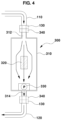
FIG. 4 is a cross-sectional view showing the external odor sensor of the device for collecting odor data according to embodiments of the present invention; and -
FIG. 5 is a flowchart showing a method of collecting odor data according to embodiments of the present invention. - It should be understood that the appended drawings are not necessarily to scale, presenting a somewhat simplified representation of various preferred features illustrative of the basic principles of embodiments of the invention. The specific design features of embodiments of the present invention as disclosed herein, including, for example, specific dimensions, orientations, locations, and shapes, will be determined in part by the particular intended application and use environment.
- In the figures, reference numbers refer to the same or equivalent parts of embodiments of the present invention throughout the several figures of the drawings.
- Various exemplary embodiments will now be described more fully with reference to the accompanying drawings, in which only some exemplary embodiments are shown. Specific structural and functional details disclosed herein are merely representative for the purpose of describing exemplary embodiments. Embodiments of the present invention, however, may be embodied in many alternate forms, and should not be construed as being limited only to the exemplary embodiments set forth herein. Accordingly, while exemplary embodiments of the invention are capable of being variously modified and taking alternative forms, embodiments thereof are shown by way of example in the drawings and will herein be described in detail. It should be understood, however, that there is no intent to limit the embodiments of the present invention to the particular exemplary embodiments disclosed. On the contrary, exemplary embodiments are to cover all modifications, equivalents, and alternatives falling within the scope of the invention.
- It will be understood that, although the terms "first", "second", etc. may be used herein to describe various elements, these elements should not be limited by these terms. These terms are only used to distinguish one element from another. For example, a first element could be termed a second element, and, similarly, a second element could be termed a first element, without departing from the scope of the exemplary embodiments of the present invention.
- It will be understood that when an element is referred to as being "connected" or "coupled" to another element, it can be directly connected or coupled to the other element or intervening elements may be present. In contrast, when an element is referred to as being "directly connected" or "directly coupled" to another element, there are no intervening elements present. Other words used to describe the relationship between elements should be interpreted in a like fashion (e.g., "between" versus "directly between", "adjacent" versus "directly adjacent", etc.).
- Wherever possible, the same reference numbers will be used throughout the drawings to refer to the same or like parts. The terminology used herein is for the purpose of describing particular embodiments only and is not intended to be limiting of exemplary embodiments of the invention. As used herein, the singular forms "a", "an", and "the" are intended to include the plural forms as well, unless the context clearly indicates otherwise. It will be further understood that the terms "comprises", "comprising", "includes", and/or "including", when used herein, specify the presence of stated components, steps, operations, and/or elements, but do not preclude the presence or addition of one or more other components, steps, operations, and/or elements.
- Hereinafter, exemplary embodiments of the present invention will be described in detail with reference to the accompanying drawings.
-
FIGs. 1 and2 are schematic diagrams showing a device for collecting odor data according to embodiments of the present invention.Reference numeral 100 denotes an odor measurement chamber. - The
odor measurement chamber 100 may be manufactured in a sealed box structure having a predetermined internal volume using a transparent plate, such as an acrylic plate. - The
odor measurement chamber 100 includes agas injection hole 102 formed in a predetermined portion of the upper side thereof to inject a gas, an odor of which is to be measured, into theodor measurement chamber 100. - Preferably, a packing member made of rubber or silicone may be inserted into the
gas injection hole 102 in order to maintain sealing. - An
injector 140 configured to inject the gas, the odor of which is to be measured, into theodor measurement chamber 100 may be connected to thegas injection hole 102 in theodor measurement chamber 100. - For example, the
injector 140 is a device such as a syringe and may be filled with a gas metered in an amount corresponding to a target concentration for preset odor intensity. - An injection needle of the
injector 140 may be inserted through the packing member in thegas injection hole 102 in order to inject the gas, the odor of which is to be measured, i.e., the gas metered in an amount corresponding to a target concentration for preset odor intensity, which is charged in theinjector 140, into theodor measurement chamber 100. - Two or more different types of
internal odor sensors 200 may be disposed in theodor measurement chamber 100. - For example, a first
internal odor sensor 200A and a secondinternal odor sensor 200B, which are of different types, may be disposed in theodor measurement chamber 100. - Each of the
internal odor sensors 200 has a structure capable of suctioning and discharging a gas and capable of sensing an odor of the suctioned gas. - To this end, as shown in
FIG. 3 , each of theinternal odor sensors 200 may include afirst case 210, which includes agas inlet 212 and agas outlet 214 formed in respective ends thereof, a firstodor sensing portion 220, which is mounted in thefirst case 210 so as to be located between thegas inlet 212 and thegas outlet 214 to sense an odor of a gas, and a gasflow induction fan 230, which is mounted in thegas inlet 212 or thegas outlet 214. - The
first case 210 serves to protect the firstodor sensing portion 220, which is an odor sensing element, and the gasflow induction fan 230 serves to guide the gas, the odor of which is to be measured, to flow to thegas inlet 212, the firstodor sensing portion 220, and thegas outlet 214. - In the case in which the first
internal odor sensor 200A and the secondinternal odor sensor 200B, which are of different types, are disposed in theodor measurement chamber 100, firstodor sensing portions 220 having mutually different sensing principles may be mounted in the firstinternal odor sensor 200A and the secondinternal odor sensor 200B, respectively. Accordingly, the firstinternal odor sensor 200A and the secondinternal odor sensor 200B may be implemented as mutually different types of odor sensors. - When the gas
flow induction fan 230 of each of theinternal odor sensors 200 is driven, the gas, the odor of which is to be measured, which is injected into theodor measurement chamber 100 through thegas injection hole 102, may enter thegas inlet 212 of thefirst case 210 and then may flow to thegas outlet 214 via the firstodor sensing portion 220. At this time, the firstodor sensing portion 220 may sense an odor of the gas. - Preferably, an opening/
closing door 108 may be mounted on one side portion of theodor measurement chamber 100 in order to secure a passage for replacement of theinternal odor sensors 200. Theinternal odor sensors 200 may be replaced or an additional odor sensor may be placed in theodor measurement chamber 100 in the state in which the opening/closing door 108 is opened. - Further, an
external odor sensor 300 may be selectively connected to theodor measurement chamber 100 so as to sense an odor of the gas. - To this end, a
discharge hole 104, through which the gas in theodor measurement chamber 100 is discharged to the outside, and areturn hole 106, through which the gas discharged to the outside returns back to theodor measurement chamber 100, are formed in one side portion of theodor measurement chamber 100. - In addition, a first
gas circulation line 110 and a secondgas circulation line 120 are connected to thedischarge hole 104 and thereturn hole 106 in theodor measurement chamber 100, respectively. - The
external odor sensor 300, which is of a different type than theinternal odor sensors 200, may be disposed outside theodor measurement chamber 100 so as to be connected between the firstgas circulation line 110 and the secondgas circulation line 120. - The
external odor sensor 300 has a structure capable of circulating a gas along a predetermined path in a manner of suctioning a gas from a gas suction source and discharging the suctioned gas back to the gas suction source. - To this end, as shown in
FIG. 4 , theexternal odor sensor 300 may include asecond case 310, which includes agas inlet 312 and agas outlet 314 formed in respective ends thereof, a secondodor sensing portion 320, which is mounted in thesecond case 310 so as to be located between thegas inlet 312 and thegas outlet 314 to sense an odor of a gas, and apump 330, which is mounted in thegas inlet 312 or thegas outlet 314 to circulate the gas in theodor measurement chamber 100 so that the gas sequentially flows through the firstgas circulation line 110, the secondodor sensing portion 320, and the secondgas circulation line 120 and then returns back to theodor measurement chamber 100. - The
second case 310 serves to protect the secondodor sensing portion 320, which is an odor sensing element, and thepump 330 serves to circulate the gas, the odor of which is to be measured, along a predetermined path in a manner of suctioning the gas from a gas suction source and discharging the suctioned gas back to the gas suction source. - In addition, the
external odor sensor 300 may further includefirst connectors 340 mounted to thegas inlet 312 and thegas outlet 314 of thesecond case 310. - The
first connectors 340 mounted to thegas inlet 312 and thegas outlet 314 of thesecond case 310 may be coupled tosecond connectors 130 mounted to the firstgas circulation line 110 and the secondgas circulation line 120, respectively, whereby theexternal odor sensor 300 may be connected between the firstgas circulation line 110 and the secondgas circulation line 120. - In this case, the first
odor sensing portions 220 having mutually different sensing principles may be mounted in the firstinternal odor sensor 200A and the secondinternal odor sensor 200B of theinternal odor sensors 200, respectively, and the secondodor sensing portion 320 having another sensing principle may be mounted in theexternal odor sensor 300. Accordingly, the firstinternal odor sensor 200A, the secondinternal odor sensor 200B, and theexternal odor sensor 300 may be implemented as mutually different types of odor sensors. - When the
pump 330 of theexternal odor sensor 300 is driven, the gas, the odor of which is to be measured, which is injected into theodor measurement chamber 100, may sequentially flow through thedischarge hole 104, the firstgas circulation line 110, and thegas inlet 312 of thesecond case 310 and then may reach the secondodor sensing portion 320. At this time, the secondodor sensing portion 320 may sense an odor of the gas. Subsequently, the gas that has passed through the secondodor sensing portion 320 may sequentially flow through thegas outlet 314, the secondgas circulation line 120, and thereturn hole 106 and then may return back to theodor measurement chamber 100. - Meanwhile, data on the odor sensed by the
internal odor sensors 200 and theexternal odor sensor 300 may be transmitted to and collected in acontroller 400. - In this way, the
internal odor sensors 200 and theexternal odor sensor 300, which are of different types, may sense an odor of the same gas at the same time, whereby the sensing performance of the different types of odor sensors may be evaluated at once, and pieces of data on the odor sensed by the respective odor sensors may be collected at once. The collected odor data may be used as odor data for training artificial intelligence robots or the like, or may be used as standard data for determination of the intensity and kind of odor measured by odor measurement devices mounted in vehicles, future mobility vehicles, or the like. - Hereinafter, a method of collecting odor data according to embodiments of the present invention using the above-described configuration will be described with reference to
FIG. 5 . - First, various kinds of standard gases, odors of which are to be measured, are manufactured (S101).
- That is, various kinds of primary standard gases, the odors of which are to be measured, are manufactured, and manufacturing examples of the primary standard gases are shown in Table 1 below.
Table 1 Component Molecular Weight Density Reagent Purity [%] Primary Standard Gas Manufacturing Concentration Injection Amount [µl] Bag Capacity [l] Concentration [ppm] Formaldehyde 30.03 0.82 35.0 1,000.0 3.0 77,454.3 Acetaldehyde 44.05 0.78 85.0 20.0 3.0 2,465.7 Acrolein 56.07 0.84 90.0 50.0 3.0 5,487.8 Propionaldehyde 58.00 0.81 98.0 20.0 3.0 2,217.1 Acetone 58.08 0.78 99.5 10,000.0 3.0 1,095,335.2 n-Butyl Acetate 116.16 0.88 95.0 500.0 3.0 29,394.3 Propionic Acid 74.10 0.99 99.0 3.0 3.0 323.4 n-Butyric Acid 88.11 0.95 99.0 1.0 3.0 87.3 Methanol 21.04 0.79 99.9 5,000.0 10.0 459,720.4 - The concentration (primary concentration) of each of various kinds of standard gases may be determined using Equation 1 below.

- In Table 1 and Equation 1 above, "bag capacity (l)" represents the capacity of a storage bag configured to store a primary standard gas, and "injection amount (µl)" represents an amount of gas injected into the storage bag at each injection time.
- Subsequently, target concentrations for odor intensities of the standard gases are set in advance (S102).
- The target concentrations for odor intensities may be set in advance as reference data by skilled odor panelists individually evaluating the odor intensities and concentrations of the standard gases. Examples of setting target concentrations for odor intensities of various kinds of standard gases are shown in Table 2 below.
Table 2 Kind of Standard Gas Odor Intensity (Bad Smell Intensity) 1 2 2.5 3 3.5 4 5 Target Concent ration (ppm) Target Concent ration (ppm) Target Concent ration (ppm) Target Concent ration (ppm) Target Concent ration (ppm) Target Concent ration (ppm) Target Concent ration (ppm) Formaldehyde 4.1×10⁻¹ 1.9 3.9 8.4 18 38 170 Acetaldehyde 1.5×10⁻³ 1.5×10⁻² 4.7×10⁻² 1.5×10⁻¹ 4.6×10⁻¹ 1.4 14 Acrolein 3.0×10⁻² 1.4×10⁻¹ 2.9×10⁻¹ 6.3×10⁻¹ 1.4 2.9 13 Propionaldehyde 1.5×10⁻³ 1.5×10⁻² 4.6×10⁻² 1.4×10⁻¹ 4.5×10⁻¹ 1.4 13 Acetone 30 110 210 400 760 1400 5200 n-Butyl Acetate 6.6×10⁻² 5.0×10⁻¹ 1.4 3.8 10 29 220 Propionic Acid (Once) 1.7×10⁻³ 8.4×10⁻³ 1.9×10⁻² 4.1×10⁻² 9.0×10⁻² 2.0×10⁻¹ 9.7×10⁻¹ n-Butyric Acid (Once) 9.6×10⁻⁵ 7.0×10⁻⁴ 1.9×10⁻³ 5.1×10⁻³ 1.4×10⁻² 3.7×10⁻² 2.7×10⁻¹ Methanol 57 200 374 700 1300 2500 8600 - As shown in Table 2 above, odor intensity (bad smell intensity) may be classified into 1, 2, 2.5, 3, 3.5, 4, and 5, and the target concentration for odor intensity may increase from odor intensity 1 to odor intensity 5.
- In detail, since the target concentration for odor intensity is set to increase from odor intensity 1 to odor intensity 5, odor intensity 1 corresponds to an odor that a person may barely feel, odor intensity 3 corresponds to an odor that a person may easily feel, and odor intensity 5 corresponds to an odor that a person may strongly feel.
- For example, as shown in Table 2 above, when the standard gas is formaldehyde, the target concentration for odor intensity 1 may be set to 4.1 × 10⁻¹ ppm, the target concentration for odor intensity 3 may be set to 8.4 ppm, and the target concentration for odor intensity 5 may be set to 170 ppm.
- Subsequently, the standard gases are metered in an amount corresponding to target concentrations for preset odor intensities (S103).
- Examples of metering the standard gases in an amount corresponding to target concentrations (secondary concentrations) for preset odor intensities are shown in Tables 3A and 3B below.
Table 3A Component Odor Intensity 2 Odor Intensity 2.5 Odor Intensity 3 Target Concent ration [ppb] Substantial Volume of Chamber [l] Injection Amount [ml] Target Concent ration [ppb] Substantial Volume of Chamber [l] Injection Amount [ml] Target Concent ration [ppb] Substantial Volume of Chamber [l] Injection Amount [ml] Formaldehyde 1900.0 46.0 1.13 3900.0 46.0 2.316 8400 46.0 4.99 Acetaldehyde 15.0 46.0 0.28 47.0 46.0 0.88 150 46.0 2.80 Acrolein 140.0 46.0 1.17 290.0 46.0 2.43 630 46.0 5.28 Propionaldehyde 15 46.0 0.31 46 46.0 0.95 140 46.0 2.90 Acetone 110000 46.0 4.62 210000 46.0 8.82 400000 46.0 16.80 n-Butyl Acetate 500 46.0 0.78 1400 46.0 2.19 3800 46.0 5.95 Propionic Acid 8.4 46.0 1.19 19.0 46.0 2.70 41 46.0 5.83 n-Butyric Acid 0.7 46.0 0.37 1.9 46.0 1.00 5.1 46.0 2.69 Methanol 200000 46.0 20.0122 374000 46.0 37.4227 700000 46.0 70.0426 Table 3B Component Odor Intensity 3.5 Odor Intensity 4 Target Concent ration [ppb] Substantial Volume of Chamber [l] Injection Amount [ml] Target Concent ration [ppb] Substantial Volume of Chamber [l] Injection Amount [ml] Formaldehyde 18000 46.0 10.690 38000 46.0 22.57 Acetaldehyde 460 46.0 8.58 1400 46.0 26.12 Acrolein 1400 46.0 11.74 2900 46.0 24.31 Propionaldehyde 450 46.0 9.34 1400 46.0 29.05 Acetone 760000 46.0 31.92 1400000 46.0 58.79 n-Butyl Acetate 10000 46.0 15.65 29000 46.0 45.38 Propionic Acid 90 46.0 12.80 200 46.0 28.45 n-Butyric Acid 14 46.0 7.38 37 46.0 19.51 Methanol 1300000 46.0 130.0791 2500000 46.0 250.1520 - The target concentration (secondary concentration) for odor intensity may be determined using Equation 2 below.

- In Tables 3A and 3B and Equation 2 above, "injection amount (ml)" represents an amount of gas metered so as to correspond to a target concentration for specific odor intensity so as to be injected into the odor measurement chamber, and "substantial volume of chamber" represents a volume obtained by subtracting the volume of an internal odor sensor disposed in the odor measurement chamber from the total volume of the odor measurement chamber.
- The injection amount (ml) of the gas injected into the odor measurement chamber, i.e., the amount of gas metered so as to correspond to a target concentration for specific odor intensity, needs to be determined based on the substantial volume of the odor measurement chamber.
- Subsequently, a gas metered in an amount corresponding to a target concentration for specific odor intensity is injected into the odor measurement chamber (S104).
- For example, the
injector 140, which is a device such as a syringe, is inserted into the storage bag storing a primary standard gas to suction the standard gas in the storage bag. In this case, theinjector 140 suctions the gas metered in an amount corresponding to a target concentration for preset odor intensity. Accordingly, the gas metered in an amount corresponding to a target concentration for preset odor intensity may be filled in theinjector 140. Subsequently, the injection needle of theinjector 140 may be inserted through the packing member in thegas injection hole 102 to inject the gas, the odor of which is to be measured, i.e., the gas metered in an amount corresponding to a target concentration for preset odor intensity, which is charged in theinjector 140, into theodor measurement chamber 100. - Subsequently, two or more different types of
internal odor sensors 200 disposed in theodor measurement chamber 100 may sense an odor of the gas (S105). - In detail, when the gas
flow induction fan 230 of each of theinternal odor sensors 200 is driven in response to a control signal of the controller, the gas, the odor of which is to be measured, i.e., the gas metered in an amount corresponding to a target concentration for specific odor intensity, which is injected into theodor measurement chamber 100 through thegas injection hole 102, may enter thegas inlet 212 of thefirst case 210 and then may flow to thegas outlet 214 via the firstodor sensing portion 220. At this time, the firstodor sensing portion 220 may sense an odor of the gas. - Further, the gas injected into the
odor measurement chamber 100 may sequentially flow through the firstgas circulation line 110 connected to the outside of theodor measurement chamber 100, theexternal odor sensor 300, and the secondgas circulation line 120 and then may return back to theodor measurement chamber 100. At this time, theexternal odor sensor 300 may sense an odor of the gas (S106). - In detail, when the
pump 330 of theexternal odor sensor 300 is driven in response to a control signal of the controller, the gas, the odor of which is to be measured, i.e., the gas metered in an amount corresponding to a target concentration for specific odor intensity, which is injected into theodor measurement chamber 100, may sequentially flow through the firstgas circulation line 110 and thegas inlet 312 of thesecond case 310 and then may reach the secondodor sensing portion 320. At this time, the secondodor sensing portion 320 may sense an odor of the gas. Subsequently, the gas that has passed through the secondodor sensing portion 320 may sequentially flow through thegas outlet 314, the secondgas circulation line 120, and thereturn hole 106 and then may return back to theodor measurement chamber 100. - At this time, odor data of the gas sensed by the
internal odor sensors 200 and odor data of the gas sensed by theexternal odor sensor 300 may be transmitted to and collected in the controller 400 (S107). - That is, odor data of the gas sensed by the
internal odor sensors 200 and odor data of the gas sensed by theexternal odor sensor 300 may be transmitted to thecontroller 400 and may be stored in a memory of the controller. - In this way, the
internal odor sensors 200 and theexternal odor sensor 300, which are of different types, may sense an odor of the gas having the same target concentration at the same time, whereby the sensing performance of the different types of odor sensors may be evaluated at once, and pieces of data on the odor sensed by the respective odor sensors may be collected at once. The collected odor data may be used as odor data for training artificial intelligence robots or the like or may be used as standard data for determination of the intensity and kind of odor measured by odor measurement devices mounted in vehicles, future mobility vehicles, or the like. - Meanwhile, the
internal odor sensors 200 and theexternal odor sensor 300, which are disposed inside and outside theodor measurement chamber 100, may repeatedly sense an odor of a specific standard gas according to target concentrations for various odor intensities. - To this end, when the
internal odor sensors 200 and theexternal odor sensor 300 sense an odor of a gas previously injected into the odor measurement chamber 100 (a gas metered in an amount corresponding to a target concentration for odor intensity lower by one level than that of a gas to be injected subsequently thereto, e.g., a gas having a target concentration corresponding to odor intensity 2) and data on the sensed odor is completely collected in the controller, a new gas (a gas metered in an amount corresponding to a target concentration for odor intensity higher by one level than that of the gas injected prior thereto, e.g., a gas having a target concentration corresponding to odor intensity 2.5) needs to be injected into theodor measurement chamber 100 so that the odor thereof is sensed. - For example, as shown in Tables 3A and 3B above, in the case of formaldehyde among various kinds of standard gases, the target concentration for odor intensity 2 is 1900.0 ppb, and the injection amount of the gas injected into the odor measurement chamber (the amount of gas metered so as to correspond to a target concentration for the corresponding odor intensity) is 1.13 ml. However, because the target concentration for odor intensity 2.5 is 3900.0 ppb, the injection amount of a gas that is to be newly injected into the odor measurement chamber (the amount of gas metered so as to correspond to a target concentration for the corresponding odor intensity) needs to be increased to 2.316 ml.
- In this case, when a gas metered in an amount corresponding to a target concentration for odor intensity higher by one level is newly injected into the
odor measurement chamber 100, the amount of gas to be newly injected into theodor measurement chamber 100 may be equivalent to an amount obtained by subtracting the amount of gas metered so as to correspond to a target concentration for odor intensity lower by one level, i.e., the amount of gas previously injected into theodor measurement chamber 100, from the amount of gas metered so as to correspond to a target concentration for odor intensity higher by one level. - For example, in the case of formaldehyde among various kinds of standard gases, the amount of gas having a target concentration (1900.0 ppb) for odor intensity 2, i.e., the amount of gas previously injected into the
odor measurement chamber 100, is 1.13 ml, and the amount of gas having a target concentration (3900.0 ppb) for odor intensity 2.5, i.e., the amount of gas to be newly injected into theodor measurement chamber 100, is 2.316 ml. In this case, since 1.13 ml of formaldehyde gas is already present in theodor measurement chamber 100, 1.186 ml of formaldehyde gas, which is obtained by subtracting 1.13 ml from 2.316 ml, may be additionally injected into theodor measurement chamber 100. - In this way, when a gas metered in an amount corresponding to a target concentration for odor intensity higher by one level is newly injected into the
odor measurement chamber 100 in order to repeatedly measure an odor of the corresponding standard gas according to target concentrations for various odor intensities, the gas is additionally injected into theodor measurement chamber 100 by an amount that is obtained by subtracting the amount of gas metered so as to correspond to a target concentration for odor intensity lower by one level, i.e., the amount of gas previously injected into theodor measurement chamber 100, from the amount of gas metered so as to correspond to a target concentration for odor intensity higher by one level. Accordingly, a standard gas reagent may be saved, and odor measurement tests may be continuously carried out without unnecessary waste of the standard gas reagent. - As is apparent from the above description, embodiments of the present invention have the following effects.
- First, after target concentrations for odor intensities of various kinds of gases, the odors of which are to be measured, are set in advance, a specific gas is metered in an amount corresponding to a target concentration for preset odor intensity, and the odor of the gas is sensed by different types of odor sensors, whereby data on the odor sensed by the odor sensors may be collected regardless of the type or kind of odor sensor, and the collected odor data may be used as standard data for determination of the intensity and kind of odor.
- Second, since different types of odor sensors sense an odor of the same gas at the same time, the sensing performance of the different types of odor sensors may be evaluated at once and pieces of data on the odor sensed by the respective odor sensors may be collected at once.
- Third, the collected data on the odor sensed by the different types of odor sensors may be used as odor data for training artificial intelligence robots or the like or may be used as standard data for determination of the intensity and kind of odor measured by odor measurement devices mounted in vehicles, future mobility vehicles, or the like.
- Embodiments of the present invention have been described above with reference to exemplary embodiments. The embodiments described in the specification and shown in the accompanying drawings are illustrative only and are not intended to represent all aspects of all embodiments of the invention. Therefore, the embodiments of the present invention are not limited to the embodiments presented herein, and it is to be understood by those skilled in the art that various modifications or changes can be made without departing from the technical spirit or scope of the invention as disclosed in the appended claims.
- For example, further embodiments of the invention are as follows:
- According to a first further embodiment, there is provided a system for collecting odor data, the system comprising: an odor measurement chamber comprising a gas injection hole, a discharge hole, and a return hole; internal odor sensors disposed in the odor measurement chamber, wherein the internal odor sensors are of different types from each other, and wherein the internal odor sensors are configured to sense an odor of a gas injected into the odor measurement chamber; an external odor sensor disposed outside the odor measurement chamber, wherein the external odor sensor is configured to sense the odor of the gas; a first gas circulation line having a first end connected to the discharge hole and a second end connected to the external odor sensor; a second gas circulation line having a first end connected to the return hole and a second end connected to the external odor sensor; and a controller configured to collect data on the odor sensed by the internal odor sensors and the external odor sensor.
- According to a second further embodiment, there is provided the system of the first further embodiment, further comprising an injector connectable to the gas injection hole, the injector being configured to inject the gas into the odor measurement chamber.
- According to a third further embodiment, there is provided the system of the first or second further embodiment, wherein the injector is filled with the gas metered in an amount corresponding to a target concentration for a preset odor intensity.
Claims (12)
- A device for collecting odor data, the device comprising:an odor measurement chamber comprising a gas injection hole;a first gas circulation line and a second gas circulation line selectively connected to the odor measurement chamber;internal odor sensors disposed in the odor measurement chamber, wherein the internal odor sensors are of different types from each other; andan external odor sensor disposed outside the odor measurement chamber and connected to the first gas circulation line and the second gas circulation line.
- The device of claim 1, further comprising an injector connected to the gas injection hole, the injector being configured to inject a gas into the odor measurement chamber.
- The device of claim 2, wherein the injector is filled with the gas metered in an amount corresponding to a target concentration for preset odor intensity.
- The device of one of claims 1-3, wherein each of the internal odor sensors comprises:a first case comprising a gas inlet and a gas outlet provided in respective ends thereof;a first odor sensing portion disposed in the first case between the gas inlet and the gas outlet, the first odor sensing portion being configured to sense an odor of a gas; anda gas flow induction fan mounted in the gas inlet or the gas outlet.
- The device of one of claims 1-4, wherein the external odor sensor comprises:a second case comprising a gas inlet and a gas outlet provided in respective ends thereof;first connectors mounted to the gas inlet and the gas outlet, the first connectors being configured to be coupled to second connectors mounted to the first gas circulation line and the second gas circulation line, respectively;a second odor sensing portion disposed in the second case so as to be located between the gas inlet and the gas outlet, the second odor sensing portion being configured to sense an odor of a gas; anda pump mounted in the gas inlet or the gas outlet, the pump being configured to circulate the gas in the odor measurement chamber so that the gas sequentially flows through the first gas circulation line, the second odor sensing portion, and the second gas circulation line and returns back to the odor measurement chamber.
- The device of one of claims 1-5, further comprising a controller configured to collect data on an odor sensed by the internal odor sensors and the external odor sensor.
- The device of one of claims 1-6, further comprising an opening/closing door mounted on one side portion of the odor measurement chamber, wherein the opening/closing door is configured to provide a passage for replacement of the internal odor sensors.
- A method of collecting odor data, the method comprising:injecting a gas metered in an amount corresponding to a target concentration for a preset odor intensity into an odor measurement chamber;sensing, by internal odor sensors disposed in the odor measurement chamber, an odor of the gas, wherein the internal odor sensors are of different types from each other;sensing, by an external odor sensor, the odor of the gas during a process in which the gas injected into the odor measurement chamber sequentially flows through a first gas circulation line connected to an outside of the odor measurement chamber, the external odor sensor, and a second gas circulation line and returns back to the odor measurement chamber; andcollecting, by a controller, data on the odor sensed by the internal odor sensors and the external odor sensor.
- The method of claim 8, further comprising obtaining the gas metered in the amount corresponding to the target concentration for the preset odor intensity, wherein obtaining the gas comprises:manufacturing various kinds of standard gases;setting target concentrations for odor intensities of the standard gases in advance; andmetering the standard gases in an amount corresponding to the set target concentrations for odor intensities.
- The method of claim 8 or 9, further comprising:determining an amount of the gas to be metered that corresponds to the target concentration for the preset odor intensity plus one level;subtracting the amount of the gas already injected into the odor measurement chamber from the amount of the gas to be metered that corresponds to the target concentration for the preset odor intensity plus one level to obtain an additional amount of the gas to be injected; andinjecting the additional amount of the gas into the odor measurement chamber.
- The method of one of claims 8-10, wherein each of the internal odor sensors comprises:a first case comprising a gas inlet and a gas outlet provided in respective ends thereof;a first odor sensing portion disposed in the first case between the gas inlet and the gas outlet, wherein the first odor sensing portion senses the odor of the gas; anda gas flow induction fan mounted in the gas inlet or the gas outlet.
- The method of one of claims 8-11, wherein the external odor sensor comprises:a second case comprising a gas inlet and a gas outlet provided in respective ends thereof;first connectors mounted to the gas inlet and the gas outlet, wherein the first connectors are coupled to second connectors mounted to the first gas circulation line and the second gas circulation line, respectively;a second odor sensing portion disposed in the second case between the gas inlet and the gas outlet, wherein the second odor sensing portion senses the odor of the gas; anda pump mounted in the gas inlet or the gas outlet, wherein the pump circulates the gas in the odor measurement chamber so that the gas sequentially flows through the first gas circulation line, the second odor sensing portion, and the second gas circulation line and returns back to the odor measurement chamber.
Applications Claiming Priority (1)
| Application Number | Priority Date | Filing Date | Title |
|---|---|---|---|
| KR1020230057423A KR20240160734A (en) | 2023-05-03 | 2023-05-03 | Device for collecting odor data and method for collecting odor data using the same |
Publications (1)
| Publication Number | Publication Date |
|---|---|
| EP4459278A1 true EP4459278A1 (en) | 2024-11-06 |
Family
ID=89474785
Family Applications (1)
| Application Number | Title | Priority Date | Filing Date |
|---|---|---|---|
| EP24150552.8A Pending EP4459278A1 (en) | 2023-05-03 | 2024-01-05 | Device for collecting odor data and method for collecting odor data using the same |
Country Status (3)
| Country | Link |
|---|---|
| EP (1) | EP4459278A1 (en) |
| KR (1) | KR20240160734A (en) |
| CN (1) | CN118897044A (en) |
Families Citing this family (1)
| Publication number | Priority date | Publication date | Assignee | Title |
|---|---|---|---|---|
| KR102912639B1 (en) * | 2025-03-13 | 2026-01-14 | 주식회사 일리아스에이아이 | Digital olfactory data service platform |
Citations (6)
| Publication number | Priority date | Publication date | Assignee | Title |
|---|---|---|---|---|
| US5627307A (en) * | 1995-11-20 | 1997-05-06 | Fortec Co., Ltd. | Method for measuring intensity index of odor |
| US6277649B1 (en) * | 1998-08-10 | 2001-08-21 | Michael Markelov | Recirculation analysis apparatus and method |
| US20130061692A1 (en) * | 2011-08-25 | 2013-03-14 | Muresan Enterprize | Electronic nose apparatus |
| US20140099729A1 (en) * | 2012-08-13 | 2014-04-10 | Andreas Mershin | Methods and Apparatus for Artificial Olfaction |
| US20170368904A1 (en) * | 2016-06-27 | 2017-12-28 | Hyundai Motor Company | Odor reproducing apparatus of hvac system for vehicle |
| US20180110457A1 (en) * | 2015-04-03 | 2018-04-26 | Olfaxis, Llc | Apparatus, method, and system for testing human olfactory systems |
-
2023
- 2023-05-03 KR KR1020230057423A patent/KR20240160734A/en active Pending
- 2023-10-18 CN CN202311348218.1A patent/CN118897044A/en active Pending
-
2024
- 2024-01-05 EP EP24150552.8A patent/EP4459278A1/en active Pending
Patent Citations (6)
| Publication number | Priority date | Publication date | Assignee | Title |
|---|---|---|---|---|
| US5627307A (en) * | 1995-11-20 | 1997-05-06 | Fortec Co., Ltd. | Method for measuring intensity index of odor |
| US6277649B1 (en) * | 1998-08-10 | 2001-08-21 | Michael Markelov | Recirculation analysis apparatus and method |
| US20130061692A1 (en) * | 2011-08-25 | 2013-03-14 | Muresan Enterprize | Electronic nose apparatus |
| US20140099729A1 (en) * | 2012-08-13 | 2014-04-10 | Andreas Mershin | Methods and Apparatus for Artificial Olfaction |
| US20180110457A1 (en) * | 2015-04-03 | 2018-04-26 | Olfaxis, Llc | Apparatus, method, and system for testing human olfactory systems |
| US20170368904A1 (en) * | 2016-06-27 | 2017-12-28 | Hyundai Motor Company | Odor reproducing apparatus of hvac system for vehicle |
Also Published As
| Publication number | Publication date |
|---|---|
| KR20240160734A (en) | 2024-11-12 |
| US20240369521A1 (en) | 2024-11-07 |
| CN118897044A (en) | 2024-11-05 |
Similar Documents
| Publication | Publication Date | Title |
|---|---|---|
| CA1291795C (en) | Blood analyzer | |
| KR101807802B1 (en) | Method for measuring breath alcohol concentration and apparatus therefor | |
| Carrieri et al. | Adjustment to concentration-dilution of spot urine samples: correlation between specific gravity and creatinine | |
| US8357542B2 (en) | Suspended particulate matter measurement apparatus and suspended particulate matter measurement method using the same | |
| CA3056855A1 (en) | A breath-condensate analyser | |
| US20120118044A1 (en) | Method and system for managing a pollution-prevention facility | |
| CN102239405A (en) | Method for determining an analyte in a water sample by means of a mobile water analysis arrangement | |
| EP2479561A1 (en) | Ion selective electrode cartridge | |
| WO2016161261A1 (en) | Apparatus, method, and system for testing human olfactory systems | |
| KR101256414B1 (en) | water pollution measurement system by using gas sensor | |
| DE29511566U1 (en) | Mobile handheld device with biosensor | |
| CN118897044A (en) | Device for collecting odor data and method for collecting odor data using the same | |
| US12631608B2 (en) | Device for collecting odor data and method for collecting odor data using the same | |
| US7084646B2 (en) | Method of detecting a gas bubble in a liquid | |
| DE20000122U1 (en) | Mobile handheld device with reusable biosensor | |
| US20240310372A1 (en) | Method and device for detecting biomolecule | |
| JP3087687B2 (en) | Liquid component measuring device | |
| EP4455660A1 (en) | Device for measuring odor and method for measuring odor using the same | |
| EP4459277B1 (en) | System for measuring odor and method for measuring odor using the same | |
| Lestina et al. | Laboratory evaluation of two passive alcohol sensors. | |
| Mráz et al. | Biological monitoring of N, N-dimethylformamide. Reference value for N-methylcarbamoyl adduct at the N-terminal valine of globin as a biomarker of chronic occupational exposure | |
| Törnqvist | Is ambient ethene a cancer risk factor? | |
| JP3216838B2 (en) | Gas sampling method and apparatus | |
| WO2020222990A1 (en) | Liquid sensor assemblies, apparatus, and methods | |
| CN116893130A (en) | Kit for white blood cell count, white blood cell count system, method and medium |
Legal Events
| Date | Code | Title | Description |
|---|---|---|---|
| PUAI | Public reference made under article 153(3) epc to a published international application that has entered the european phase |
Free format text: ORIGINAL CODE: 0009012 |
|
| STAA | Information on the status of an ep patent application or granted ep patent |
Free format text: STATUS: THE APPLICATION HAS BEEN PUBLISHED |
|
| AK | Designated contracting states |
Kind code of ref document: A1 Designated state(s): AL AT BE BG CH CY CZ DE DK EE ES FI FR GB GR HR HU IE IS IT LI LT LU LV MC ME MK MT NL NO PL PT RO RS SE SI SK SM TR |
|
| P01 | Opt-out of the competence of the unified patent court (upc) registered |
Free format text: CASE NUMBER: APP_12947/2025 Effective date: 20250314 |
|
| STAA | Information on the status of an ep patent application or granted ep patent |
Free format text: STATUS: REQUEST FOR EXAMINATION WAS MADE |
|
| 17P | Request for examination filed |
Effective date: 20250506 |