EP4459251A1 - Temperature-measurement terminal structure - Google Patents
Temperature-measurement terminal structure Download PDFInfo
- Publication number
- EP4459251A1 EP4459251A1 EP22914394.6A EP22914394A EP4459251A1 EP 4459251 A1 EP4459251 A1 EP 4459251A1 EP 22914394 A EP22914394 A EP 22914394A EP 4459251 A1 EP4459251 A1 EP 4459251A1
- Authority
- EP
- European Patent Office
- Prior art keywords
- temperature
- temperature sensor
- measurement
- terminal
- terminal structure
- Prior art date
- Legal status (The legal status is an assumption and is not a legal conclusion. Google has not performed a legal analysis and makes no representation as to the accuracy of the status listed.)
- Pending
Links
Images

Classifications
-
- G—PHYSICS
- G01—MEASURING; TESTING
- G01K—MEASURING TEMPERATURE; MEASURING QUANTITY OF HEAT; THERMALLY-SENSITIVE ELEMENTS NOT OTHERWISE PROVIDED FOR
- G01K1/00—Details of thermometers not specially adapted for particular types of thermometer
- G01K1/16—Special arrangements for conducting heat from the object to the sensitive element
-
- B—PERFORMING OPERATIONS; TRANSPORTING
- B60—VEHICLES IN GENERAL
- B60L—PROPULSION OF ELECTRICALLY-PROPELLED VEHICLES; SUPPLYING ELECTRIC POWER FOR AUXILIARY EQUIPMENT OF ELECTRICALLY-PROPELLED VEHICLES; ELECTRODYNAMIC BRAKE SYSTEMS FOR VEHICLES IN GENERAL; MAGNETIC SUSPENSION OR LEVITATION FOR VEHICLES; MONITORING OPERATING VARIABLES OF ELECTRICALLY-PROPELLED VEHICLES; ELECTRIC SAFETY DEVICES FOR ELECTRICALLY-PROPELLED VEHICLES
- B60L53/00—Methods of charging batteries, specially adapted for electric vehicles; Charging stations or on-board charging equipment therefor; Exchange of energy storage elements in electric vehicles
- B60L53/10—Methods of charging batteries, specially adapted for electric vehicles; Charging stations or on-board charging equipment therefor; Exchange of energy storage elements in electric vehicles characterised by the energy transfer between the charging station and the vehicle
- B60L53/14—Conductive energy transfer
- B60L53/16—Connectors, e.g. plugs or sockets, specially adapted for charging electric vehicles
-
- G—PHYSICS
- G01—MEASURING; TESTING
- G01K—MEASURING TEMPERATURE; MEASURING QUANTITY OF HEAT; THERMALLY-SENSITIVE ELEMENTS NOT OTHERWISE PROVIDED FOR
- G01K1/00—Details of thermometers not specially adapted for particular types of thermometer
- G01K1/14—Supports; Fastening devices; Arrangements for mounting thermometers in particular locations
-
- G—PHYSICS
- G01—MEASURING; TESTING
- G01K—MEASURING TEMPERATURE; MEASURING QUANTITY OF HEAT; THERMALLY-SENSITIVE ELEMENTS NOT OTHERWISE PROVIDED FOR
- G01K1/00—Details of thermometers not specially adapted for particular types of thermometer
- G01K1/14—Supports; Fastening devices; Arrangements for mounting thermometers in particular locations
- G01K1/143—Supports; Fastening devices; Arrangements for mounting thermometers in particular locations for measuring surface temperatures
-
- G—PHYSICS
- G01—MEASURING; TESTING
- G01K—MEASURING TEMPERATURE; MEASURING QUANTITY OF HEAT; THERMALLY-SENSITIVE ELEMENTS NOT OTHERWISE PROVIDED FOR
- G01K7/00—Measuring temperature based on the use of electric or magnetic elements directly sensitive to heat ; Power supply therefor, e.g. using thermoelectric elements
- G01K7/16—Measuring temperature based on the use of electric or magnetic elements directly sensitive to heat ; Power supply therefor, e.g. using thermoelectric elements using resistive elements
- G01K7/22—Measuring temperature based on the use of electric or magnetic elements directly sensitive to heat ; Power supply therefor, e.g. using thermoelectric elements using resistive elements the element being a non-linear resistance, e.g. thermistor
-
- H—ELECTRICITY
- H01—ELECTRIC ELEMENTS
- H01R—ELECTRICALLY-CONDUCTIVE CONNECTIONS; STRUCTURAL ASSOCIATIONS OF A PLURALITY OF MUTUALLY-INSULATED ELECTRICAL CONNECTING ELEMENTS; COUPLING DEVICES; CURRENT COLLECTORS
- H01R13/00—Details of coupling devices of the kinds covered by groups H01R12/70 or H01R24/00 - H01R33/00
- H01R13/66—Structural association with built-in electrical component
- H01R13/665—Structural association with built-in electrical component with built-in electronic circuit
- H01R13/6683—Structural association with built-in electrical component with built-in electronic circuit with built-in sensor
-
- B—PERFORMING OPERATIONS; TRANSPORTING
- B60—VEHICLES IN GENERAL
- B60L—PROPULSION OF ELECTRICALLY-PROPELLED VEHICLES; SUPPLYING ELECTRIC POWER FOR AUXILIARY EQUIPMENT OF ELECTRICALLY-PROPELLED VEHICLES; ELECTRODYNAMIC BRAKE SYSTEMS FOR VEHICLES IN GENERAL; MAGNETIC SUSPENSION OR LEVITATION FOR VEHICLES; MONITORING OPERATING VARIABLES OF ELECTRICALLY-PROPELLED VEHICLES; ELECTRIC SAFETY DEVICES FOR ELECTRICALLY-PROPELLED VEHICLES
- B60L2240/00—Control parameters of input or output; Target parameters
- B60L2240/10—Vehicle control parameters
- B60L2240/36—Temperature of vehicle components or parts
-
- H—ELECTRICITY
- H01—ELECTRIC ELEMENTS
- H01R—ELECTRICALLY-CONDUCTIVE CONNECTIONS; STRUCTURAL ASSOCIATIONS OF A PLURALITY OF MUTUALLY-INSULATED ELECTRICAL CONNECTING ELEMENTS; COUPLING DEVICES; CURRENT COLLECTORS
- H01R13/00—Details of coupling devices of the kinds covered by groups H01R12/70 or H01R24/00 - H01R33/00
- H01R13/02—Contact members
- H01R13/10—Sockets for co-operation with pins or blades
- H01R13/11—Resilient sockets
- H01R13/111—Resilient sockets co-operating with pins having a circular transverse section
-
- Y—GENERAL TAGGING OF NEW TECHNOLOGICAL DEVELOPMENTS; GENERAL TAGGING OF CROSS-SECTIONAL TECHNOLOGIES SPANNING OVER SEVERAL SECTIONS OF THE IPC; TECHNICAL SUBJECTS COVERED BY FORMER USPC CROSS-REFERENCE ART COLLECTIONS [XRACs] AND DIGESTS
- Y02—TECHNOLOGIES OR APPLICATIONS FOR MITIGATION OR ADAPTATION AGAINST CLIMATE CHANGE
- Y02T—CLIMATE CHANGE MITIGATION TECHNOLOGIES RELATED TO TRANSPORTATION
- Y02T90/00—Enabling technologies or technologies with a potential or indirect contribution to GHG emissions mitigation
- Y02T90/10—Technologies relating to charging of electric vehicles
- Y02T90/14—Plug-in electric vehicles
Definitions
- the present disclosure relates to the technical field of the manufacturing of electric energy transmission devices, and particularly to a temperature-measurement terminal structure.
- measure temperature ways can be divided into two categories, i.e., contact temperature measurement and non-contact temperature measurement, based on whether a measuring body is in contact with a measured medium.
- the non-contact temperature measurement has a wide temperature measurement range because the temperature measurement element is not in contact with the measured medium, and the upper limit of temperature measurement is not limited in principle.
- the non-contact temperature measurement generally has a larger error in temperature measurement due to being affected by the emissivity of the object, the distance from the measured object to the temperature measurement element, and other media such as smoke, dust, and water vapor.
- the heat is transferred by radiation, which takes a long time and has a slow speed of temperature measurement, failing to meet many occasions that require timeliness and accuracy of temperature measurement.
- the contact temperature measurement is simple and reliable with a high measurement accuracy.
- the present disclosure aims to provide a temperature-measurement terminal structure, which can increase a contact area by embedding a temperature sensor on a terminal, and reduce errors of a temperature measurement by omitting a heat conductor, thereby ensuring safe charging.
- the terminal includes an embedding groove with an inner contact surface.
- the temperature sensor is at least partially disposed in the embedding groove, and has a temperature measurement surface attached to the inner contact surface.
- the temperature sensor is provided with a plugging port for being connected to an electric transmission member.
- the inner contact surface is a flat surface or a curved surface.
- the terminal has a cylindrical section, the embedding groove is a circumferential groove disposed on the cylindrical section, and the temperature measurement surface is an arc surface matched with the circumferential groove.
- the arc surface has a radian of 28° to 180°.
- a fixing portion is further included, and the fixing portion and the temperature sensor are connected end to end to form a ring disposed in the circumferential groove.
- the fixing portion is elastic.
- Heat-conducting silica gel is disposed between the inner contact surface and the temperature measurement surface.
- the temperature sensor is an NTC temperature sensor or a PTC temperature sensor.
- a radial thickness of the temperature sensor is less than or equal to a depth of the embedding groove.
- the temperature-measurement terminal structure according to the present disclosure has the following effects: By disposing the temperature sensor in the groove, the temperature sensor can be more firmly attached to the terminal, so that the temperature signal collected by the temperature sensor is closer to the actual temperature change, with small error.
- the temperature sensor By connecting the plugging member with the temperature sensor, the temperature sensor can be conveniently installed before being connected to a wire, so as to meet the requirements of complicated installation environments.
- the temperature sensor is arc-shaped and matched with the circumferential groove, so as to be conveniently mounted on the terminal. With the assistance of the fixing portion, the temperature sensor is more closely attached to the circumferential groove, and the measured temperature is closer to the real value.
- the heat-conducting silica gel can assist the connection between the terminal and the temperature sensor, increase the effective contact area between the terminal and the temperature sensor, increase the adhesive force, and avoid the reduction in the effective contact area due to vibration or the reduction in the heat-conducting efficiency due to generation of an air gap.
- the present disclosure discloses a temperature-measurement terminal structure, as illustrated in FIGS. 1 to 4 , which includes a terminal 1 and a temperature sensor 2.
- the terminal 1 includes an embedding groove 11 with an inner contact surface 111.
- the temperature sensor 2 is at least partially disposed in the embedding groove 11, and has a temperature measurement surface 21 attached to the inner contact surface 111. According to the temperature measurement mode of the charging structure for the charging automobile in the prior art, the temperature sensor 2 is generally disposed on the surface of the terminal 1, and the temperature sensor 2 directly measures the temperature of the terminal 1. However, due to the influence of the shape of the temperature sensor 2, it is difficult for the temperature sensor 2 to have a sufficient contact area with the terminal; in addition, when the temperature is measured by means of disposing a heat conductor, the temperature measured by the temperature sensor 2 is not accurate due to the transmission and consumption of the temperature of the terminal 1.
- the terminal 1 is provided with the embedding groove 11 in which the temperature sensor 2 is embedded, so that the temperature measurement surface 21 of the temperature sensor 2 can be fully attached to the inner contact surface 11 of the embedding groove 11, which not only omits the heat conductor but also ensures the contact area between the temperature sensor 2 and the terminal 1, so that the temperature value of the terminal 1 measured by the temperature sensor 2 is closer to the real value.
- the temperature sensor 2 is provided with a plugging port 22, which is used to be connected to an electric transmission member.
- the electric transmission member may be a plugging member or a wire for electrically connecting the temperature sensor 2 with a control end or a detection end. Disposing the plugging port 22 on the temperature sensor 2 can facilitate the installation of the temperature sensor 2, i.e., the temperature sensor 2 can be installed on the terminal 1 before being connected to a wire, which can satisfy more complicated installation environments, and also make the wiring inside the charging socket more reasonable.
- the plugging port 22 may be disposed on a side surface of the terminal 1, and the plugging member or the wire may be disposed in a radial direction of the terminal 1.
- a boss on the temperature sensor 2 it is possible to dispose a boss on the temperature sensor 2, and dispose the plugging port 22 on the boss (e.g., a side surface of the boss), as illustrated in FIG. 2 , so that the plugging member or the wire is parallel to an axial direction of the terminal 1.
- the inner contact surface 111 is a flat surface or a curved surface. Accordingly, when the inner contact surface 111 is a flat surface, the temperature measurement surface 21 which is attached to the inner contact surface 111 is also a flat surface, and when the inner contact surface 111 is a curved surface, the temperature measuring surface 21 attached to the inner contact surface 111 is also a curved surface.
- the design of curved surface can increase the contact area between the temperature sensor 2 and the terminal 1 in a limited space, so as to obtain a more accurate temperature value.
- the terminal 1 has a cylindrical section 3, the embedding groove 11 is a circumferential groove disposed on the cylindrical section 3, and the temperature measurement surface 21 is an arc surface matched with the circumferential groove. Since the temperature sensor 2 is disposed in the circumferential groove, and the arc surface is curved along the circumferential groove, a more accurate temperature value can be obtained from the inner contact surface 111 attached to the circumferential groove.
- the arc surface has a radian of 28° to 180°.
- a large radian of the arc surface means a longer length of the temperature measurement surface of the temperature sensor 2 and a small radian of the arc surface means means a small contact area between the temperature sensor 2 and the terminal 1, which leads to inaccurate measured temperature.
- the inventor carries out relevant tests, in which the same terminals 1 are adopted, each having the same embedding groove 11 which is a circumferential groove on the cylindrical section 3, and the temperature sensors 2 with the same radius and different radians are adopted, so as to measure the temperature of the terminals 1 and obtain an absolute value of each difference between each measured temperature and the actual temperature.
- Table 1 Influence of the Radian of the Arc Surface on the Temperature Measurement Effect Radian of the Arc Surface (°) 27 28 30 35 40 50 60 70 80 100 120 140 160 180 Difference between the measured temperature and the actual temperature (°C) 0.51 0.5 0.49 0.45 0.42 0.38 0.32 0.28 0.23 0.19 0.15 0.11 0. 1 0
- the radian of the arc surface when the radian of the arc surface is less than 28°, the temperature difference between the measured temperature and the actual temperature is greater than 0.5 °C, which is unqualified; and when the radian of the arc surface is greater than or equal to 36°, the temperature difference between the measured temperature and the actual temperature is less than 0.5 °C, which is qualified.
- the radian reaches 180°, there is no difference between the measured temperature and the actual temperature. Therefore, the inventor prefers that the radian is 180°, i.e., it is ideal that the arc surface is semi-circular.
- the opening of the temperature sensor 2 is smaller than the diameter of the embedding groove 11 of the terminal 1, making it impossible to install the temperature sensor 2, so the inventor selects the radian of the arc surface to be 28° to 180°.
- a fixing portion 4 is further included, as illustrated in FIG. 4 .
- the fixing portion 4 and the temperature sensor 2 are connected end to end to form a ring which can be disposed in the circumferential groove.
- One end of the fixing portion 4 may be hinged with the temperature sensor 2, and the other end thereof is clamped or latched with the temperature sensor 2, so that the fixing portion 4 and the temperature sensor 2 form a ring that is at least partially embedded in the circumferential groove.
- the fixing portion 4 is elastic.
- the elastic fixing portion 4 may be sleeved in the circumferential groove after two ends thereof are connected to the temperature sensor 2, making it more convenient to use.
- heat-conducting silica gel is disposed between the inner contact surface 111 and the temperature measurement surface 21.
- the heat-conducting silica gel can assist the connection between the terminal 1 and the temperature sensor 2, improve the effective contact area, increase the adhesive force, and avoid the reduction in the effective contact area due to vibration or the reduction in the heat-conducting efficiency due to generation of an air gap.
- the filled heat-conducting silica gel can serve as a buffer between the temperature sensor 2 and the terminal 1.
- the temperature sensor 2 is an NTC (Negative Temperature Coefficient) temperature sensor or a PTC (Positive Temperature Coefficient) temperature sensor.
- the NTC temperature sensor and the PTC temperature sensor are convenient to use, have a resistance value ranging of 0.1 to 100 k ⁇ for arbitrary selection, are easy to be processed into complex shapes, can be mass-produced, have good stability and strong overload capacity, and are suitable for products such as adapters requiring small sizes and stable performances.
- the PTC sensor is more stable than the NTC sensor.
- a bimetal temperature sensor includes two metals with different expansion coefficients, in which the metal with a larger expansion coefficient bends when the temperature changes, so that the bimetal temperature sensor has a good vibration resistance and is suitable for electric automobiles.
- a radial thickness of the temperature sensor 2 is less than or equal to a depth of the embedding groove 11.
- the temperature sensor 2 is embedded in the embedding groove 11. Since an area of the terminal 1 where the temperature sensor 2 is located needs to be plugged with a mating terminal, if the temperature sensor 2 protrudes from the embedding groove 11, it will affect the plugging of the terminal 1 into the mating terminal. Therefore, the radial thickness of the temperature sensor 2 is less than or equal to the depth of the embedding groove 11, so as to ensure that the temperature sensor 2 will not affect the plugging of the terminal.
- the terminal 1 may also be provided with a recess for accommodating a plugging member or a wire connected to the plugging port 22 of the temperature sensor 2, so as to ensure that neither the temperature sensor 2 nor the electrical connector connected thereto will hinder the plugging between the terminal 1 and the mating terminal.
Landscapes
- Physics & Mathematics (AREA)
- General Physics & Mathematics (AREA)
- Engineering & Computer Science (AREA)
- Nonlinear Science (AREA)
- Power Engineering (AREA)
- Transportation (AREA)
- Mechanical Engineering (AREA)
- Microelectronics & Electronic Packaging (AREA)
- Measuring Temperature Or Quantity Of Heat (AREA)
- Details Of Connecting Devices For Male And Female Coupling (AREA)
Abstract
Description
- The present disclosure claims priority to
Chinese Patent Application No. 202123312383.0, entitled "temperature-measurement terminal structure", and filed on December 27, 2021 - The present disclosure relates to the technical field of the manufacturing of electric energy transmission devices, and particularly to a temperature-measurement terminal structure.
- With the rapid development of the new energy technologies, the number of the new energy automobiles is also increasing. At present, both a charging gun head and a charging socket of a new energy automobile have charging terminals of plugged structure. When the automobile is charged, the current at the charging terminals increases rapidly, resulting in a sharp rise in heat generation. Thus, for the sake of safety, many manufacturers provide temperature measurement devices at the charging terminals. There are many ways to measure temperature, for example, measure temperature ways can be divided into two categories, i.e., contact temperature measurement and non-contact temperature measurement, based on whether a measuring body is in contact with a measured medium. The non-contact temperature measurement has a wide temperature measurement range because the temperature measurement element is not in contact with the measured medium, and the upper limit of temperature measurement is not limited in principle. However, the non-contact temperature measurement generally has a larger error in temperature measurement due to being affected by the emissivity of the object, the distance from the measured object to the temperature measurement element, and other media such as smoke, dust, and water vapor. Moreover, in the non-contact temperature measurement, the heat is transferred by radiation, which takes a long time and has a slow speed of temperature measurement, failing to meet many occasions that require timeliness and accuracy of temperature measurement. The contact temperature measurement is simple and reliable with a high measurement accuracy. However, there are two common problems with contact temperature measurement: one is that the contact area between the temperature sensor and the terminal surface is insufficient, resulting in inconsistency between the measured temperature value and the actual temperature value; the other is that a heat conductor is often needed to be connected to both the terminal and the temperature sensor, and the temperature at the terminal is transferred to the temperature sensor through the heat conductor, during which a temperature loss inevitably occurs, resulting in an inaccurate temperature measurement, and moreover, additional space is needed to place the heat conductor. Therefore, there is an urgent need for a new solution to solve the above problems in the prior art.
- The present disclosure aims to provide a temperature-measurement terminal structure, which can increase a contact area by embedding a temperature sensor on a terminal, and reduce errors of a temperature measurement by omitting a heat conductor, thereby ensuring safe charging.
- It is a first aspect of the present disclosure to provide a temperature-measurement terminal structure, including a terminal and a temperature sensor. The terminal includes an embedding groove with an inner contact surface. The temperature sensor is at least partially disposed in the embedding groove, and has a temperature measurement surface attached to the inner contact surface.
- The temperature sensor is provided with a plugging port for being connected to an electric transmission member.
- The inner contact surface is a flat surface or a curved surface.
- The terminal has a cylindrical section, the embedding groove is a circumferential groove disposed on the cylindrical section, and the temperature measurement surface is an arc surface matched with the circumferential groove.
- The arc surface has a radian of 28° to 180°.
- A fixing portion is further included, and the fixing portion and the temperature sensor are connected end to end to form a ring disposed in the circumferential groove.
- The fixing portion is elastic.
- Heat-conducting silica gel is disposed between the inner contact surface and the temperature measurement surface.
- The temperature sensor is an NTC temperature sensor or a PTC temperature sensor.
- A radial thickness of the temperature sensor is less than or equal to a depth of the embedding groove.
- The temperature-measurement terminal structure according to the present disclosure has the following effects:
By disposing the temperature sensor in the groove, the temperature sensor can be more firmly attached to the terminal, so that the temperature signal collected by the temperature sensor is closer to the actual temperature change, with small error. - By connecting the plugging member with the temperature sensor, the temperature sensor can be conveniently installed before being connected to a wire, so as to meet the requirements of complicated installation environments.
- The temperature sensor is arc-shaped and matched with the circumferential groove, so as to be conveniently mounted on the terminal. With the assistance of the fixing portion, the temperature sensor is more closely attached to the circumferential groove, and the measured temperature is closer to the real value.
- The heat-conducting silica gel can assist the connection between the terminal and the temperature sensor, increase the effective contact area between the terminal and the temperature sensor, increase the adhesive force, and avoid the reduction in the effective contact area due to vibration or the reduction in the heat-conducting efficiency due to generation of an air gap.
- The drawings, which are incorporated in and constitute a part of the specification, illustrate the embodiments of the present disclosure and together with the description thereof, serve to explain the principles of the present disclosure.
-
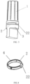
FIG. 1 illustrates a structural diagram of a terminal of a temperature-measurement terminal structure according to the present disclosure. -
FIG. 2 illustrates a structural diagram of a temperature sensor of a temperature-measurement terminal structure according to the present disclosure. -
FIG. 3 illustrates a structural diagram of a temperature-measurement terminal structure according to the present disclosure. -
FIG. 4 illustrates a structural diagram of a fixing portion of a temperature-measurement terminal structure according to the present disclosure. - 1: terminal; 11: embedding groove; 111: inner contact surface; 2: temperature sensor; 21: temperature measurement surface; 22: plugging port; 3: cylindrical section; and 4: fixing portion.
- Various exemplary embodiments of the present disclosure will now be described in detail with reference to the drawings. It should be noted that the relative arrangements, numerical expressions and values of components and steps set forth in these embodiments do not limit the scope of the present disclosure unless otherwise specified.
- The following description of at least one exemplary embodiment is merely illustrative and is in no way intended to limit the present disclosure and the application or use thereof.
- Techniques, methods and devices known to those of ordinary skill in the art may not be discussed in detail, but they should be regarded as part of the specification under appropriate circumstances.
- In all examples illustrated and discussed here, any specific value should be interpreted as illustrative only and not as a limitation. Therefore, other examples of the exemplary embodiments may have different values.
- The present disclosure discloses a temperature-measurement terminal structure, as illustrated in
FIGS. 1 to 4 , which includes aterminal 1 and atemperature sensor 2. Theterminal 1 includes anembedding groove 11 with aninner contact surface 111. - The
temperature sensor 2 is at least partially disposed in theembedding groove 11, and has atemperature measurement surface 21 attached to theinner contact surface 111. According to the temperature measurement mode of the charging structure for the charging automobile in the prior art, thetemperature sensor 2 is generally disposed on the surface of theterminal 1, and thetemperature sensor 2 directly measures the temperature of theterminal 1. However, due to the influence of the shape of thetemperature sensor 2, it is difficult for thetemperature sensor 2 to have a sufficient contact area with the terminal; in addition, when the temperature is measured by means of disposing a heat conductor, the temperature measured by thetemperature sensor 2 is not accurate due to the transmission and consumption of the temperature of theterminal 1. According to the solution provided by the present disclosure, theterminal 1 is provided with theembedding groove 11 in which thetemperature sensor 2 is embedded, so that thetemperature measurement surface 21 of thetemperature sensor 2 can be fully attached to theinner contact surface 11 of theembedding groove 11, which not only omits the heat conductor but also ensures the contact area between thetemperature sensor 2 and theterminal 1, so that the temperature value of theterminal 1 measured by thetemperature sensor 2 is closer to the real value. - In an exemplary embodiment, as illustrated in
FIG. 2 , thetemperature sensor 2 is provided with aplugging port 22, which is used to be connected to an electric transmission member. The electric transmission member may be a plugging member or a wire for electrically connecting thetemperature sensor 2 with a control end or a detection end. Disposing theplugging port 22 on thetemperature sensor 2 can facilitate the installation of thetemperature sensor 2, i.e., thetemperature sensor 2 can be installed on theterminal 1 before being connected to a wire, which can satisfy more complicated installation environments, and also make the wiring inside the charging socket more reasonable. Theplugging port 22 may be disposed on a side surface of theterminal 1, and the plugging member or the wire may be disposed in a radial direction of theterminal 1. Alternatively, it is possible to dispose a boss on thetemperature sensor 2, and dispose theplugging port 22 on the boss (e.g., a side surface of the boss), as illustrated inFIG. 2 , so that the plugging member or the wire is parallel to an axial direction of theterminal 1. - In an exemplary embodiment, the
inner contact surface 111 is a flat surface or a curved surface. Accordingly, when theinner contact surface 111 is a flat surface, thetemperature measurement surface 21 which is attached to theinner contact surface 111 is also a flat surface, and when theinner contact surface 111 is a curved surface, thetemperature measuring surface 21 attached to theinner contact surface 111 is also a curved surface. The design of curved surface can increase the contact area between thetemperature sensor 2 and theterminal 1 in a limited space, so as to obtain a more accurate temperature value. - In an exemplary embodiment, as illustrated in
FIG. 3 , theterminal 1 has acylindrical section 3, theembedding groove 11 is a circumferential groove disposed on thecylindrical section 3, and thetemperature measurement surface 21 is an arc surface matched with the circumferential groove. Since thetemperature sensor 2 is disposed in the circumferential groove, and the arc surface is curved along the circumferential groove, a more accurate temperature value can be obtained from theinner contact surface 111 attached to the circumferential groove. - In the case where the radius of the
temperature sensor 2 is fixed, a large radian of the arc surface means a longer length of the temperature measurement surface of thetemperature sensor 2 and a small radian of the arc surface means means a small contact area between thetemperature sensor 2 and theterminal 1, which leads to inaccurate measured temperature. In order to select an optimum radian, the inventor carries out relevant tests, in which thesame terminals 1 are adopted, each having the same embeddinggroove 11 which is a circumferential groove on thecylindrical section 3, and thetemperature sensors 2 with the same radius and different radians are adopted, so as to measure the temperature of theterminals 1 and obtain an absolute value of each difference between each measured temperature and the actual temperature. The absolute value greater than 0.5°Cis considered unqualified, and the results are recorded in Table 1.Table 1: Influence of the Radian of the Arc Surface on the Temperature Measurement Effect Radian of the Arc Surface (°) 27 28 30 35 40 50 60 70 80 100 120 140 160 180 Difference between the measured temperature and the actual temperature (°C) 0.51 0.5 0.49 0.45 0.42 0.38 0.32 0.28 0.23 0.19 0.15 0.11 0. 1 0 - As can be seen from Table 1, when the radian of the arc surface is less than 28°, the temperature difference between the measured temperature and the actual temperature is greater than 0.5 °C, which is unqualified; and when the radian of the arc surface is greater than or equal to 36°, the temperature difference between the measured temperature and the actual temperature is less than 0.5 °C, which is qualified. When the radian reaches 180°, there is no difference between the measured temperature and the actual temperature. Therefore, the inventor prefers that the radian is 180°, i.e., it is ideal that the arc surface is semi-circular. However, when the radian is greater than 180°, the opening of the
temperature sensor 2 is smaller than the diameter of the embeddinggroove 11 of theterminal 1, making it impossible to install thetemperature sensor 2, so the inventor selects the radian of the arc surface to be 28° to 180°. - In an exemplary embodiment, a fixing
portion 4 is further included, as illustrated inFIG. 4 . The fixingportion 4 and thetemperature sensor 2 are connected end to end to form a ring which can be disposed in the circumferential groove. One end of the fixingportion 4 may be hinged with thetemperature sensor 2, and the other end thereof is clamped or latched with thetemperature sensor 2, so that the fixingportion 4 and thetemperature sensor 2 form a ring that is at least partially embedded in the circumferential groove. - In an exemplary embodiment, the fixing
portion 4 is elastic. Theelastic fixing portion 4 may be sleeved in the circumferential groove after two ends thereof are connected to thetemperature sensor 2, making it more convenient to use. - In an exemplary embodiment, heat-conducting silica gel is disposed between the
inner contact surface 111 and thetemperature measurement surface 21. The heat-conducting silica gel can assist the connection between the terminal 1 and thetemperature sensor 2, improve the effective contact area, increase the adhesive force, and avoid the reduction in the effective contact area due to vibration or the reduction in the heat-conducting efficiency due to generation of an air gap. Meanwhile, the filled heat-conducting silica gel can serve as a buffer between thetemperature sensor 2 and theterminal 1. - In an exemplary embodiment, the
temperature sensor 2 is an NTC (Negative Temperature Coefficient) temperature sensor or a PTC (Positive Temperature Coefficient) temperature sensor. The NTC temperature sensor and the PTC temperature sensor are convenient to use, have a resistance value ranging of 0.1 to 100 kΩ for arbitrary selection, are easy to be processed into complex shapes, can be mass-produced, have good stability and strong overload capacity, and are suitable for products such as adapters requiring small sizes and stable performances. The PTC sensor is more stable than the NTC sensor. A bimetal temperature sensor includes two metals with different expansion coefficients, in which the metal with a larger expansion coefficient bends when the temperature changes, so that the bimetal temperature sensor has a good vibration resistance and is suitable for electric automobiles. - In an exemplary embodiment, a radial thickness of the
temperature sensor 2 is less than or equal to a depth of the embeddinggroove 11. In some cases, thetemperature sensor 2 is embedded in the embeddinggroove 11. Since an area of theterminal 1 where thetemperature sensor 2 is located needs to be plugged with a mating terminal, if thetemperature sensor 2 protrudes from the embeddinggroove 11, it will affect the plugging of theterminal 1 into the mating terminal. Therefore, the radial thickness of thetemperature sensor 2 is less than or equal to the depth of the embeddinggroove 11, so as to ensure that thetemperature sensor 2 will not affect the plugging of the terminal. Meanwhile, theterminal 1 may also be provided with a recess for accommodating a plugging member or a wire connected to the pluggingport 22 of thetemperature sensor 2, so as to ensure that neither thetemperature sensor 2 nor the electrical connector connected thereto will hinder the plugging between the terminal 1 and the mating terminal. - Although some specific embodiments of the present disclosure have been described in detail by way of examples, it should be understood by those skilled in the art that the above examples are illustrative only and are not intended to limit the scope of the present disclosure. It should be understood by those skilled in the art that the above embodiments can be modified without departing from the scope and spirit of the present disclosure. The scope of the present disclosure is defined by the appended claims.
Claims (10)
- A temperature-measurement terminal structure, comprising a terminal (1) and a temperature sensor (2);wherein the terminal (1) comprises an embedding groove (11) with an inner contact surface (111); andthe temperature sensor (2) is at least partially disposed in the embedding groove (11), and has a temperature measurement surface (21) attached to the inner contact surface (111).
- The temperature-measurement terminal structure according to claim 1, wherein the temperature sensor (2) is provided with a plugging port (22) for being connected to an electric transmission member.
- The temperature-measurement terminal structure according to claim 1, wherein the inner contact surface (111) is a flat surface or a curved surface.
- The temperature-measurement terminal structure according to claim 1, wherein the terminal (1) has a cylindrical section (3), the embedding groove (11) is a circumferential groove disposed on the cylindrical section (3), and the temperature measurement surface (21) is an arc surface matched with the circumferential groove.
- The temperature-measurement terminal structure according to claim 4, wherein the arc surface has a radian of 28° to 180°.
- The temperature-measurement terminal structure according to claim 4, further comprising a fixing portion (4), wherein the fixing portion (4) and the temperature sensor (2) are connected end to end to form a ring disposed in the circumferential groove.
- The temperature-measurement terminal structure according to claim 6, wherein the fixing portion (4) is elastic.
- The temperature-measurement terminal structure according to claim 1, wherein heat-conducting silica gel is disposed between the inner contact surface (111) and the temperature measurement surface (21).
- The temperature-measurement terminal structure according to claim 1, wherein the temperature sensor (2) is an NTC temperature sensor or a PTC temperature sensor.
- The temperature-measurement terminal structure according to claim 1, wherein a radial thickness of the temperature sensor (2) is less than or equal to a depth of the embedding groove (11).
Applications Claiming Priority (2)
| Application Number | Priority Date | Filing Date | Title |
|---|---|---|---|
| CN202123312383.0U CN217211165U (en) | 2021-12-27 | 2021-12-27 | Terminal temperature measurement structure |
| PCT/CN2022/140299 WO2023125140A1 (en) | 2021-12-27 | 2022-12-20 | Temperature-measurement terminal structure |
Publications (2)
| Publication Number | Publication Date |
|---|---|
| EP4459251A1 true EP4459251A1 (en) | 2024-11-06 |
| EP4459251A4 EP4459251A4 (en) | 2025-04-30 |
Family
ID=82785093
Family Applications (1)
| Application Number | Title | Priority Date | Filing Date |
|---|---|---|---|
| EP22914394.6A Pending EP4459251A4 (en) | 2021-12-27 | 2022-12-20 | CONNECTION STRUCTURE FOR TEMPERATURE MEASUREMENT |
Country Status (4)
| Country | Link |
|---|---|
| US (1) | US20250060256A1 (en) |
| EP (1) | EP4459251A4 (en) |
| CN (1) | CN217211165U (en) |
| WO (1) | WO2023125140A1 (en) |
Families Citing this family (2)
| Publication number | Priority date | Publication date | Assignee | Title |
|---|---|---|---|---|
| CN217211165U (en) * | 2021-12-27 | 2022-08-16 | 长春捷翼汽车零部件有限公司 | Terminal temperature measurement structure |
| CN219736599U (en) * | 2023-03-27 | 2023-09-22 | 长春捷翼汽车科技股份有限公司 | Terminal temperature measurement structure |
Family Cites Families (9)
| Publication number | Priority date | Publication date | Assignee | Title |
|---|---|---|---|---|
| CN104089721B (en) * | 2014-06-30 | 2018-06-12 | 国家电网公司 | A kind of cable terminal apparatus for monitoring temperature measurement |
| DE102015115657B3 (en) * | 2015-09-17 | 2017-02-09 | Harting Ag & Co. Kg | electrical contact element |
| DE102016001572A1 (en) * | 2016-02-11 | 2017-08-17 | Sumitomo Wiring Systems, Ltd. | Charging connector, terminal fitting and method for fixing a sensor to a terminal fitting |
| CN205958136U (en) * | 2016-07-18 | 2017-02-15 | 苏州三星电子有限公司 | Pipeline temperature sensor |
| CN106329674B (en) * | 2016-11-16 | 2018-10-12 | 国网黑龙江省电力有限公司大兴安岭供电公司 | Take electricity and stable-pressure device |
| BE1025169B1 (en) * | 2017-04-24 | 2018-11-28 | Phoenix Contact E-Mobility Gmbh | Connector part with a temperature monitoring device |
| CN207050872U (en) * | 2017-08-02 | 2018-02-27 | 厦门安普格电气有限公司 | The improved structure of contact arm wireless temperature measuring device |
| CN211868646U (en) * | 2020-03-06 | 2020-11-06 | 四川启物者科技有限公司 | 3D printing pen head capable of preventing material returning |
| CN217211165U (en) * | 2021-12-27 | 2022-08-16 | 长春捷翼汽车零部件有限公司 | Terminal temperature measurement structure |
-
2021
- 2021-12-27 CN CN202123312383.0U patent/CN217211165U/en active Active
-
2022
- 2022-12-20 WO PCT/CN2022/140299 patent/WO2023125140A1/en not_active Ceased
- 2022-12-20 US US18/724,165 patent/US20250060256A1/en active Pending
- 2022-12-20 EP EP22914394.6A patent/EP4459251A4/en active Pending
Also Published As
| Publication number | Publication date |
|---|---|
| CN217211165U (en) | 2022-08-16 |
| WO2023125140A1 (en) | 2023-07-06 |
| US20250060256A1 (en) | 2025-02-20 |
| EP4459251A4 (en) | 2025-04-30 |
Similar Documents
| Publication | Publication Date | Title |
|---|---|---|
| CN112254872B (en) | High-temperature pressure sensor with vacuum heat insulation cavity | |
| US20250060256A1 (en) | Temperature-measurement terminal structure | |
| EP4390348A1 (en) | Temperature measurement structure, charging apparatus and motor vehicle | |
| CN217211164U (en) | Terminal temperature measurement structure | |
| CN212963756U (en) | Temperature sensor, temperature sensor group and temperature measuring device | |
| CN216750372U (en) | Elastic conduction temperature measurement assembly and socket | |
| CN219161479U (en) | Terminal temperature measurement structure and connector | |
| CN219736599U (en) | Terminal temperature measurement structure | |
| US20210018344A1 (en) | Lightning proof sensor | |
| CN220649797U (en) | Two-wire Pt100 temperature sensor for traction inverter air inlet | |
| CN207019811U (en) | Temperature sensor | |
| CN213184258U (en) | Reactor core detector assembly thermocouple cold end shell, compensation temperature equalizer and assembly | |
| CN222460878U (en) | Novel temperature sensing detects device | |
| CN223581212U (en) | A temperature measuring ring for cable accessories | |
| CN208173915U (en) | Connection terminal component and connector | |
| CN223783760U (en) | A temperature sensor for a gearbox | |
| CN219919538U (en) | Peripheral elastic heat transfer's heat conduction mechanism | |
| CN223138826U (en) | Two-wire NTC temperature sensor for urban rail train air conditioning units | |
| CN221099915U (en) | Food thermometer | |
| CN222013333U (en) | Mounting structure of charging gun temperature sensor | |
| CN223243675U (en) | A temperature and pressure integrated sensor | |
| CN221260173U (en) | Pressure sensor of common rail system | |
| CN221350310U (en) | A temperature sensing control device | |
| CN222850170U (en) | Temperature measurement structure of terminal | |
| CN218330293U (en) | An in-line air temperature sensor |
Legal Events
| Date | Code | Title | Description |
|---|---|---|---|
| STAA | Information on the status of an ep patent application or granted ep patent |
Free format text: STATUS: THE INTERNATIONAL PUBLICATION HAS BEEN MADE |
|
| PUAI | Public reference made under article 153(3) epc to a published international application that has entered the european phase |
Free format text: ORIGINAL CODE: 0009012 |
|
| STAA | Information on the status of an ep patent application or granted ep patent |
Free format text: STATUS: REQUEST FOR EXAMINATION WAS MADE |
|
| 17P | Request for examination filed |
Effective date: 20240725 |
|
| AK | Designated contracting states |
Kind code of ref document: A1 Designated state(s): AL AT BE BG CH CY CZ DE DK EE ES FI FR GB GR HR HU IE IS IT LI LT LU LV MC ME MK MT NL NO PL PT RO RS SE SI SK SM TR |
|
| P01 | Opt-out of the competence of the unified patent court (upc) registered |
Free format text: CASE NUMBER: APP_62542/2024 Effective date: 20241123 |
|
| REG | Reference to a national code |
Ref country code: DE Ref legal event code: R079 Free format text: PREVIOUS MAIN CLASS: G01K0001140000 Ipc: G01K0001160000 |
|
| DAV | Request for validation of the european patent (deleted) | ||
| DAX | Request for extension of the european patent (deleted) | ||
| A4 | Supplementary search report drawn up and despatched |
Effective date: 20250328 |
|
| RIC1 | Information provided on ipc code assigned before grant |
Ipc: H01R 13/11 20060101ALI20250324BHEP Ipc: H01R 13/66 20060101ALI20250324BHEP Ipc: G01K 1/143 20210101ALI20250324BHEP Ipc: G01K 7/22 20060101ALI20250324BHEP Ipc: G01K 1/16 20060101AFI20250324BHEP |
|
| STAA | Information on the status of an ep patent application or granted ep patent |
Free format text: STATUS: EXAMINATION IS IN PROGRESS |
|
| 17Q | First examination report despatched |
Effective date: 20251125 |