EP4459233A2 - Aircraft and method of adjusting a pilot workload - Google Patents
Aircraft and method of adjusting a pilot workload Download PDFInfo
- Publication number
- EP4459233A2 EP4459233A2 EP24200033.9A EP24200033A EP4459233A2 EP 4459233 A2 EP4459233 A2 EP 4459233A2 EP 24200033 A EP24200033 A EP 24200033A EP 4459233 A2 EP4459233 A2 EP 4459233A2
- Authority
- EP
- European Patent Office
- Prior art keywords
- flight
- pilot
- operator
- workload
- aircraft
- Prior art date
- Legal status (The legal status is an assumption and is not a legal conclusion. Google has not performed a legal analysis and makes no representation as to the accuracy of the status listed.)
- Pending
Links
Images



Classifications
-
- G—PHYSICS
- G08—SIGNALLING
- G08G—TRAFFIC CONTROL SYSTEMS
- G08G5/00—Traffic control systems for aircraft
- G08G5/30—Flight plan management
- G08G5/34—Flight plan management for flight plan modification
-
- G—PHYSICS
- G06—COMPUTING OR CALCULATING; COUNTING
- G06Q—INFORMATION AND COMMUNICATION TECHNOLOGY [ICT] SPECIALLY ADAPTED FOR ADMINISTRATIVE, COMMERCIAL, FINANCIAL, MANAGERIAL OR SUPERVISORY PURPOSES; SYSTEMS OR METHODS SPECIALLY ADAPTED FOR ADMINISTRATIVE, COMMERCIAL, FINANCIAL, MANAGERIAL OR SUPERVISORY PURPOSES, NOT OTHERWISE PROVIDED FOR
- G06Q10/00—Administration; Management
- G06Q10/06—Resources, workflows, human or project management; Enterprise or organisation planning; Enterprise or organisation modelling
- G06Q10/063—Operations research, analysis or management
- G06Q10/0639—Performance analysis of employees; Performance analysis of enterprise or organisation operations
- G06Q10/06393—Score-carding, benchmarking or key performance indicator [KPI] analysis
-
- G—PHYSICS
- G08—SIGNALLING
- G08G—TRAFFIC CONTROL SYSTEMS
- G08G5/00—Traffic control systems for aircraft
- G08G5/20—Arrangements for acquiring, generating, sharing or displaying traffic information
- G08G5/21—Arrangements for acquiring, generating, sharing or displaying traffic information located onboard the aircraft
-
- A—HUMAN NECESSITIES
- A61—MEDICAL OR VETERINARY SCIENCE; HYGIENE
- A61B—DIAGNOSIS; SURGERY; IDENTIFICATION
- A61B5/00—Measuring for diagnostic purposes; Identification of persons
- A61B5/16—Devices for psychotechnics; Testing reaction times ; Devices for evaluating the psychological state
- A61B5/165—Evaluating the state of mind, e.g. depression, anxiety
-
- A—HUMAN NECESSITIES
- A61—MEDICAL OR VETERINARY SCIENCE; HYGIENE
- A61B—DIAGNOSIS; SURGERY; IDENTIFICATION
- A61B5/00—Measuring for diagnostic purposes; Identification of persons
- A61B5/16—Devices for psychotechnics; Testing reaction times ; Devices for evaluating the psychological state
- A61B5/18—Devices for psychotechnics; Testing reaction times ; Devices for evaluating the psychological state for vehicle drivers or machine operators
-
- B—PERFORMING OPERATIONS; TRANSPORTING
- B60—VEHICLES IN GENERAL
- B60K—ARRANGEMENT OR MOUNTING OF PROPULSION UNITS OR OF TRANSMISSIONS IN VEHICLES; ARRANGEMENT OR MOUNTING OF PLURAL DIVERSE PRIME-MOVERS IN VEHICLES; AUXILIARY DRIVES FOR VEHICLES; INSTRUMENTATION OR DASHBOARDS FOR VEHICLES; ARRANGEMENTS IN CONNECTION WITH COOLING, AIR INTAKE, GAS EXHAUST OR FUEL SUPPLY OF PROPULSION UNITS IN VEHICLES
- B60K28/00—Safety devices for propulsion-unit control, specially adapted for, or arranged in, vehicles, e.g. preventing fuel supply or ignition in the event of potentially dangerous conditions
- B60K28/02—Safety devices for propulsion-unit control, specially adapted for, or arranged in, vehicles, e.g. preventing fuel supply or ignition in the event of potentially dangerous conditions responsive to conditions relating to the driver
-
- B—PERFORMING OPERATIONS; TRANSPORTING
- B64—AIRCRAFT; AVIATION; COSMONAUTICS
- B64D—EQUIPMENT FOR FITTING IN OR TO AIRCRAFT; FLIGHT SUITS; PARACHUTES; ARRANGEMENT OR MOUNTING OF POWER PLANTS OR PROPULSION TRANSMISSIONS IN AIRCRAFT
- B64D45/00—Aircraft indicators or protectors not otherwise provided for
- B64D45/0015—Devices specially adapted for the protection against criminal attack, e.g. anti-hijacking systems
- B64D45/0051—Devices specially adapted for the protection against criminal attack, e.g. anti-hijacking systems by monitoring passengers or crew on aircraft
- B64D45/0056—Devices specially adapted for the protection against criminal attack, e.g. anti-hijacking systems by monitoring passengers or crew on aircraft detecting passenger or crew behavior by sensors, e.g. biometrics
-
- G—PHYSICS
- G06—COMPUTING OR CALCULATING; COUNTING
- G06F—ELECTRIC DIGITAL DATA PROCESSING
- G06F3/00—Input arrangements for transferring data to be processed into a form capable of being handled by the computer; Output arrangements for transferring data from processing unit to output unit, e.g. interface arrangements
- G06F3/01—Input arrangements or combined input and output arrangements for interaction between user and computer
- G06F3/011—Arrangements for interaction with the human body, e.g. for user immersion in virtual reality
- G06F3/013—Eye tracking input arrangements
-
- G—PHYSICS
- G06—COMPUTING OR CALCULATING; COUNTING
- G06Q—INFORMATION AND COMMUNICATION TECHNOLOGY [ICT] SPECIALLY ADAPTED FOR ADMINISTRATIVE, COMMERCIAL, FINANCIAL, MANAGERIAL OR SUPERVISORY PURPOSES; SYSTEMS OR METHODS SPECIALLY ADAPTED FOR ADMINISTRATIVE, COMMERCIAL, FINANCIAL, MANAGERIAL OR SUPERVISORY PURPOSES, NOT OTHERWISE PROVIDED FOR
- G06Q10/00—Administration; Management
- G06Q10/06—Resources, workflows, human or project management; Enterprise or organisation planning; Enterprise or organisation modelling
- G06Q10/063—Operations research, analysis or management
- G06Q10/0631—Resource planning, allocation, distributing or scheduling for enterprises or organisations
- G06Q10/06311—Scheduling, planning or task assignment for a person or group
-
- G—PHYSICS
- G08—SIGNALLING
- G08G—TRAFFIC CONTROL SYSTEMS
- G08G5/00—Traffic control systems for aircraft
- G08G5/50—Navigation or guidance aids
- G08G5/53—Navigation or guidance aids for cruising
-
- A—HUMAN NECESSITIES
- A61—MEDICAL OR VETERINARY SCIENCE; HYGIENE
- A61B—DIAGNOSIS; SURGERY; IDENTIFICATION
- A61B5/00—Measuring for diagnostic purposes; Identification of persons
- A61B5/48—Other medical applications
- A61B5/486—Biofeedback
-
- B—PERFORMING OPERATIONS; TRANSPORTING
- B64—AIRCRAFT; AVIATION; COSMONAUTICS
- B64C—AEROPLANES; HELICOPTERS
- B64C13/00—Control systems or transmitting systems for actuating flying-control surfaces, lift-increasing flaps, air brakes, or spoilers
- B64C13/02—Initiating means
- B64C13/16—Initiating means actuated automatically, e.g. responsive to gust detectors
- B64C13/18—Initiating means actuated automatically, e.g. responsive to gust detectors using automatic pilot
-
- G—PHYSICS
- G06—COMPUTING OR CALCULATING; COUNTING
- G06F—ELECTRIC DIGITAL DATA PROCESSING
- G06F2203/00—Indexing scheme relating to G06F3/00 - G06F3/048
- G06F2203/01—Indexing scheme relating to G06F3/01
- G06F2203/011—Emotion or mood input determined on the basis of sensed human body parameters such as pulse, heart rate or beat, temperature of skin, facial expressions, iris, voice pitch, brain activity patterns
-
- G—PHYSICS
- G08—SIGNALLING
- G08G—TRAFFIC CONTROL SYSTEMS
- G08G5/00—Traffic control systems for aircraft
- G08G5/50—Navigation or guidance aids
- G08G5/55—Navigation or guidance aids for a single aircraft
Definitions
- the disclosure relates to a method of monitoring and adjusting pilot workload.
- Contemporary aircraft travel flight paths that generally includes a climb, a cruise, and a descent. Pilots along with flight management systems (FMS) implement the flight plan.
- the FMS may generate the flight plan by taking into account parameters specific to the aircraft and to the flight conditions such as the payload, the weight of the aircraft, the quantity of fuel onboard, temperature, wind, altitude, etc., and of the time constraints imposed by the air traffic control.
- the flight plan may describe all the waypoints or positions through which the aircraft is to pass, with the altitude and corresponding speed at each waypoint.
- the disclosure relates to a method of adjusting pilot workload during a flight includes tracking over a time period, using at least one sensor, one of inputs by a pilot indicative of a pilot workload or image sensor data or a biometric parameter indicative of a pilot stress level during flight of the aircraft. Determining, using a controller that is operatively connected to the at least one sensor, a level of one of the pilot workload or pilot stress level. The method also includes adjusting, using a controller that is operatively connected to the flight control computer, the pilot workload when the level of one of the pilot workload or pilot stress level exceeds a predetermined threshold.
- the disclosure relates to a method of adjusting a planned pilot workload before the planned flight.
- the method includes tracking over a time period, using at least one sensor, inputs by a pilot indicative of a pilot workload or image sensor data or a biometric parameter indicative of a pilot stress level during one or more flights of an aircraft prior to the assigned flight. Correlating, using a controller that is operatively connected to the at least one sensor, one of the image sensor data, biometric parameters or pilot workload with one or more time periods for analysis. Identifying, using a processor that is operatively connected to a controller, which of the one or more time periods comprise pilot workload above a threshold value based on the analysis. Adjusting, a controller that is operatively connected to the flight control computer, the pilot workload during the time periods above the threshold value of pre-planned pilot workload of the assigned flight.
- aspects of the present disclosure are directed to a method of adjusting a pilot workload during a flight.
- workload means the tasks a pilot must perform during various stages of the flight.
- portions of a flight plan such as takeoff, landing or even flying over certain geographic areas can require significant pilot attention and workload and in some cases can increase a pilot's stress level.
- Other portions of a flight plan such as cruise during long flights, may need minimal pilot attention. It can be beneficial to track a pilot's workload or stress level during flight and adjust the pilot's workload when the pilot's stress level or workload exceeds a predetermined threshold.
- the present disclosure is also directed to a method of adjusting a pre-planned workload before a fight. Since flights often take place over the same flight path, such as from city-to-city, flight data can be collected that is representative of a typical flight. During any given flight, data representing a pilot's workload or stress level can be collected and correlated with portions of a flight plan such as takeoff, landing or flying over certain geographic areas. Statistical analysis of the data can determine when a pilot has experienced high workload volumes or high stress levels. The data can be saved and analyzed to understand when a pilot will likely experience increases in workload for a similar future planned flight. Prior to a future flight, it can be beneficial to understand when a pilot will likely experience higher workloads during the flight. In this scenario, it may be possible to adjust the expected pilot work load during heavy workload periods by shifting tasks during the heavy workload period to light workload periods. Moreover, understanding workloads during a flight can help airlines adjust crew rosters to adjust for workload conditions.
- a set can include any number of the respectively described elements, including only one element. All directional references (e.g., radial, axial, proximal, distal, upper, lower, upward, downward, left, right, lateral, front, back, top, bottom, above, below, vertical, horizontal, clockwise, counterclockwise, upstream, downstream, forward, aft, etc.) are only used for identification purposes to aid the reader's understanding of the present disclosure, and do not create limitations, particularly as to the position, orientation, or use of the disclosure. Connection references (e.g., attached, coupled, connected, and joined) are to be construed broadly and can include intermediate members between a collection of elements and relative movement between elements unless otherwise indicated. As such, connection references do not necessarily infer that two elements are directly connected and in fixed relation to one another.
- the exemplary drawings are for purposes of illustration only and the dimensions, positions, order, and relative sizes reflected in the drawings attached hereto can vary.
- a “controller” can include at least one processor and memory.
- the memory can include Random Access Memory (RAM), Read-Only Memory (ROM), flash memory, or one or more different types of portable electronic memory, such as discs, DVDs, CD-ROMs, etc., or any suitable combination of these types of memory.
- the processor can be configured to run any suitable programs or executable instructions designed to carry out various methods, functionality, processing tasks, calculations, or the like, to enable or achieve the technical operations or operations described herein.
- the program can include a computer program product that can include machine-readable media for carrying or having machine-executable instructions or data structures stored thereon.
- Such machine-readable media can be any available media, which can be accessed by a general purpose or special purpose computer or other machine with a processor.
- a computer program can include routines, programs, objects, components, data structures, algorithms, etc., that have the technical effect of performing particular tasks or implement particular abstract data types.
- FIG. 1 schematically illustrates an aircraft 10 according to various aspects described herein.
- One or more propulsion engines 12 can be coupled to a fuselage 14, a cockpit 16 can be positioned in the fuselage 14, and wing assemblies 18 can extend outward from the fuselage 14.
- a plurality of aircraft systems 20 that enable proper operation of the aircraft 10 can be included as well as a flight control computer 22 (or "computer” 22). While a commercial aircraft has been illustrated, it is contemplated that aspects of the disclosure can be used in any type of legacy aircraft, for example, without limitation, fixed-wing, rotating-wing, rocket, or personal aircraft.
- the plurality of aircraft systems 20 can reside within the cockpit 16, within an electronics and equipment bay 23, or in other locations throughout the aircraft 10 including that they can be associated with the engines 12.
- Such aircraft systems 20 can include but are not limited to: an electrical system, an oxygen system, hydraulics and/or pneumatics system, a fuel system, a propulsion system, navigation systems, flight controls, audio/video systems, an Integrated Vehicle Health Management (IVHM) system, and systems associated with the mechanical structure of the aircraft 10.
- IVHM Integrated Vehicle Health Management
- a variety of aircraft systems 20 have been illustrated for exemplary purposes and it will be understood that they are only a few of the systems that can be included in the aircraft 10.
- a data network 26 over which the plurality of aircraft systems 20 can communicate with each other and provide information to a crew of the aircraft 10 can be included.
- the aircraft systems 20 can output various information to a flight deck 30 located in a cockpit 16 of the aircraft 10.
- a communication interface 40 can be located within the aircraft 10 and operably coupled to at least some of the plurality of aircraft systems 20.
- the communication interface 40 has been illustrated as being included in the cockpit 16. It is contemplated that the communication interface 40 can be located in other locations within the aircraft 10 including within the electronics and equipment bay 23. Although only one communication interface 40 has been illustrated, it is contemplated that the aircraft 10 can have multiple communication interfaces.
- the communication interface 40 can be utilized for communication with other aircraft or a ground station 31, such as by radio contact in a non-limiting example.
- the communication interface 40 can transmit or receive data, including audio or visual data as appropriate.
- the ground station 31 can be in communication with the data network 26 or communication interface 40.
- the ground station 31 can have a processor and software and capabilities for uploading or downloading software or data to the aircraft.
- the ground station 31 might also capability to store, analyze, and manipulate flight data with data analysis or other statistical software.
- the aircraft 10 might also have a computing system capable of storing, analyzing, and manipulating flight data with data analysis or other statistical software.
- FIG. 2 illustrates a portion of the cockpit 16 of the aircraft 10 and an exemplary flight deck 30 having various instruments 50 and flight displays 52.
- a first pilot (herein, a "pilot”) can be present in a seat 54 at the left side of the cockpit 16 and a second pilot (herein, a "co-pilot”) can be present at the right side of the cockpit 16 in a seat 55 and the flight deck 30 can be located in front of the pilot and co-pilot and can provide the flight crew with information to aid in operating the aircraft 10.
- the flight displays 52 can include either primary flight displays or multi-function displays and can display a wide range of aircraft, flight, navigation, and other information used in the operation and control of the aircraft 10. Further, both the various instruments 50 and flight displays 52 of the flight deck 30 can provide one or more visual indicia indicative of a corresponding health condition of one or more of the aircraft systems 20.
- the instruments 50 and flight displays 52 can be laid out in any manner including having fewer or more instruments or displays. Further, the flight displays 52 need not be coplanar and need not be the same size.
- a touch screen display or touch screen surface can be included in the flight display 52 and may be used by one or more flight crew members, including the pilot and co-pilot, to interact with the systems of the aircraft 10. Such touch screen surface can take any suitable form including that of a liquid crystal display (LCD) and can use various physical or electrical attributes to sense inputs from the flight crew. It is contemplated that the flight display 52 can be dynamic and that one or more cursor control devices 56 and/or one or more multifunction keyboards 58 can be included in the cockpit 16 and can be used by one or more flight crew members to interact with the systems of the aircraft 10. In this manner, the flight deck 30 can be considered a user interface for the aircraft systems 20 and the aircraft 10.
- the flight control computer 22 can be operably coupled to components of the aircraft 10 including the aircraft systems 20, instruments 50, flight displays 52, touch screen surfaces, cursor control devices 56, keyboards 58, etc.
- the flight control computer 22 can receive inputs from any number of aircraft systems 20 or software programs responsible for managing the acquisition and storage of data.
- the flight control computer 22 can also be in the form of a controller, and can be connected with other controllers of the aircraft 10.
- the flight control computer 22 can include memory 60 and processing units 62, which can be running any suitable programs to implement a graphical user interface (GUI) and operating system.
- GUI graphical user interface
- the flight control computer 22 can include or be associated with, any suitable number of individual microprocessors, power supplies, storage devices, interface cards, auto flight systems, flight management computers, and other standard components.
- the flight control computer 22 can include or cooperate with any number of software programs (e.g., flight management programs) or instructions designed to carry out the various methods, process tasks, calculations, and control/display functions necessary for operation of the aircraft 10.
- the communication interface 40 can be communicably coupled to the flight control computer 22 or other processors of the aircraft 10 as well as any number of the plurality of aircraft systems 20 to transfer information on and off the aircraft 10.
- the communication interface 40 can include any desired communication mechanism capable of wirelessly linking with other systems and devices, such as by radio contact in a non-limiting example.
- one of the aircraft systems 20 can be in the form of a distress tracker 21 configured to transmit a state of aircraft distress (for example, "normal,” "abnormal,” or "distressed").
- a pilot tracking system or tracking system 100 is illustrated as being in communication with the flight control computer 22. It will be understood that the tracking system 100 can be hard wired to the flight control computer 22 or can communicate in any suitable manner with the flight control computer 22 including via wireless communication. Alternatively, the tracking system 100 can be included as a module within the flight control computer 22.
- the tracking system 100 can include at least one imaging module 102 and at least one audio module 104.
- the imaging module 102 can include an image sensor 103 configured to sense visual information about a pilot or co-pilot, such as rapid eye movement, eyes moving one direction or another, being open or closed, a direction of gaze, or a facial state such as eyebrows raised or lowered, by way of non-limiting examples and provide an output signal based thereon.
- An eye movement or body movement parameter can be stored by the tracking system 100
- the imaging module 102 or the flight control computer 22 can also be in signal communication with any of the flight displays 52, such as to display a visual indication based on the sensed visual information from the imaging module 102.
- the audio module 104 can include an audio sensor 105 configured to sense audio information about a pilot or co-pilot, such as a language being spoken in the cockpit 16, a voice volume, slurred or altered speech, a speech pattern, or sounds that can occur due to pilot or co-pilot interaction with an aircraft system 20 such as striking the flight deck 30 or typing on the multifunction keyboard 58 and provide an output signal based thereon.
- the audio module 104 can also provide audio feedback or sound to the pilot or co-pilot, such as through speakers mounted within the cockpit or through headphones worn by the pilot or co-pilot. Further, the audio module 104 can be in signal communication with the imaging module 102.
- the imaging module 102 can provide an indication for transmission through the audio module 104, such as spoken commands in a low-visibility environment within the cockpit 16.
- the audio module 104 can also provide a signal for transmission via the imaging module 102, such as a flashing light display or text-based indicator to be read by a pilot or co-pilot.
- At least one biometric sensor 106 configured to sense a biometric parameter of the pilot or co-pilot can be included in the tracking system 100.
- a biometric sensor 106 positioned on the first seat 54 can be configured to sense or detect a heart rate, breathing rate, perspiration rate, or bodily motion of the pilot when the pilot is sitting in the first seat 54.
- the biometric sensor 106 can be positioned on a wearable device such as a wrist strap or headband.
- the biometric sensor 106 can be in the form of an optical sensor, e.g. a camera that monitors the pilot or co-pilot.
- a seat tracking module 108 can control a seat distance 110 between the first seat 54 and the flight deck 30. While not shown, the second seat 55 can also include such a seat tracking module 108. Further, a seat belt sensor 112 can sense the position of a seat belt 70 on the first seat 54 or the second seat 55, such as the seat belt 70 being buckled or unbuckled.
- a haptic feedback generator 114 can be coupled or integrated with either or both of the first and second seats 54, 55.
- the haptic feedback generator 114 can be configured to vibrate, such as a steady or varying vibration pattern, to provide feedback to the pilot or co-pilot.
- the haptic feedback generator 114 can vibrate on a right-hand portion or left-hand portion of the seat 54, 55 to indicate to a pilot or co-pilot which direction to bank the aircraft 10 for correct orientation when flying.
- a timer 115 can also be included in the tracking system 100 and is illustrated as being coupled to the flight deck 30.
- the timer 115 can be positioned anywhere within or outside of the cockpit 16.
- the timer 115 can be configured to track an elapsed time of an event or to provide an alarm or other indication at a predetermined time.
- Non-limiting examples where the timer 115 can be utilized include tracking an elapsed time of flight, an elapsed time of a pilot interaction with an aircraft system 20 (such as updating flight records via the multifunction keyboard 58), tracking an elapsed sleep time, indicating a time for changing a flight direction, or indicating a wake time.
- An additional controller 120 having a processor 122 and a memory 124 can also be included in the tracking system 100.
- the controller 120 is illustrated as being coupled to the flight deck 30 and in signal communication with any or all of the flight control computer 22, instruments 50, flight displays 52, memory 60, processing unit 62, imaging module 102, audio module 104, biometric sensor 106, seat tracking module 108, seat belt sensor 112, haptic feedback generator 114, or timer 115. Dashed lines have been used to illustrate a portion of the signal connection between the above-described components. The lack of a dashed line for signal connections is done for clarity of the figures, and it will be understood that components not connected by a dashed line can nonetheless be in signal communication.
- FIG. 3 schematically illustrates components of the tracking system 100 in exemplary communicative connection, where a separate controller 120 is shown in signal connection with the various modules and sensors described above.
- the flight control computer 22 can be utilized or that each module or any combination of modules can include their own controller, processor, or memory.
- Arrows have been included to indicate an exemplary signal or control direction, and are provided for clarity in discussion. It will be understood that any signal communication or control between connected components in FIG. 3 can be transmitted in either direction, and an arrow's illustrated direction does not imply a one-way signal or control direction.
- a door lock module 116 with a door lock sensor 117 can further be included in the tracking system 100.
- a cockpit door 72 can include the door lock module 116 configured to sense whether the door 72 is locked or unlock.
- the module 116 can also automatically lock or unlock the door 72 based on a control signal within the tracking system 100.
- the controller 120 can be operably connected to and receive input from any or all of the flight control computer 22, image sensor 103, audio sensor 105, biometric sensor 106, seat tracking module 108, seat belt sensor 112, haptic feedback generator 114, timer 115, or door lock module 116. Any of the inputs received by the controller 120 can be stored in the memory 124.
- the memory 124 can store a history of audio input or recordings from data gathered within the cockpit 16, or an elapsed time since a pilot last interacted with a flight display 52 ( FIG. 2 ).
- the processor 122 of the controller 120 can send a signal or control command to any or all of the imaging module 102, audio module 104, seat tracking module 108, haptic feedback generator 114, or door lock module 116.
- the processor 122 can send a signal to the imaging module 102, such as a visual message to be read by the pilot or co-pilot on the flight display 52, or a command to enable or disable the image sensor 103.
- controller 120 of the tracking system 100 can issue a signal or command to another aircraft system, such as the communication interface 40 via the flight control computer 22.
- the controller 120 can communicate with an external aircraft or ground station (not shown).
- the controller 120 can also be communicatively coupled with any other aircraft system 20 as desired.
- the method 140 begins at 141 with tracking inputs by a pilot or tracking image sensor 103 data or a biometric parameters of the pilot to determine a stress level of the pilot during flight of the aircraft 10 by using at least one sensor within the tracking system 100.
- the tracking of inputs, sensor data or biometric parameters can occur over distinct periods of time such as over an entire flight, or portions of a flight such as an elapsed time over a geographic location, an elapsed time a pilot has been on-board, or an elapsed time of a flight phase such as flight take off, flight landing or cruising.
- Tracking inputs by the pilot can be an indication of the pilot's workload.
- tracking pilot input can be accomplished via the image sensor 103, such as visually detecting the pilot's hand interacting with the keyboard 58 or flight display 52.
- the controller 120 can detect that the pilot has touched or interacted with the touchscreen flight display 52.
- Tracking pilot input can also be accomplished via the flight control computer 22 which is communicatively coupled to the controller 120, including tracking that the pilot has interacted with or entered input to any cockpit system e.g. the keyboard 58 or the cursor control device 56.
- Tracking a pilot's stress level can be accomplished by tracking a pilot's eye movements or body movements from the image sensor 103 or by tracking various biometric parameters of the pilot.
- the image sensor 103 can track both the eye movements and body movements of the pilot during all or portions of the flight.
- biometric parameters of the pilot such as heart rate, breathing rate, skin temperature, and the like, can be indicative of the pilot's stress level. It should be recognized that this data can be used to make real-time decisions about pilot workload or stress level during a flight or the data can be saved to a database and processed after the flight.
- the controller 120 can determine the workload or stress level of the pilot based on the tracked pilot input, image sensor 103 data, or biometric parameter(s) from 141.
- the timer 115 in conjunction with the flight control computer 22 can indicate to the controller 120 that the pilot has input multiple inputs into various avionics systems over a short period of time and is backed up on flight control computer 22 requests.
- the controller 120 can then determine the rate at which the pilot is addressing flight control computer 22 requests and determine the workload level of the pilot.
- the controller 120 can also or alternatively determine, at 142, a stress level of the pilot based image sensor 103 data. For example, if the pilot's eyes are rapidly moving from screen to screen the controller 120 can determine the pilot stress level by correlating the movements with other real-time parameters, against pre-existing data, or above a predetermined threshold level.
- the controller 120 can also or alternatively determine, at 142, a stress level of the pilot based on the biometric parameter.
- the biometric sensor 106 can determine a pilot's rate of breathing, heart rate, pulse rate, and the like.
- the controller 120 can determine the pilot stress level by correlating any of the biometrics parameters with other real-time parameters such as data from the image sensor 103, against pre-existing data, or above a predetermined threshold level.
- the controller 120 can adjust the pilot workload during flight when one of the pilot workload or pilot stress level exceeds a predetermined threshold. For example, if the controller 120 determines that the pilot's stress level is above a predetermined threshold value based on sensor readings from one of the image sensor 103 or biometric sensor 106 then the controller 120 can be programmed to shift certain tasks such as non-critical or non-essential pilot tasks to the co-pilot or other crew member. In addition or alternatively, the controller 120 can be programmed to shift the non-critical or non-essential pilot tasks to a future time frame when the pilot has less tasks in his workload.
- the method includes, at 151, tracking inputs by a pilot, or tracking image sensor 103 data, or a biometric parameter of the pilot during flight of the aircraft 10 during one or more aircraft flights. Since flights often take place over the same flight path, such as from city-to-city, flight data can be collected that is representative of a typical flight between the two cities. At this step, it is contemplated that data can be tracked and collected from multiple flights over various time frames and preferably from flights that fly the same or similar flight paths. The data can be tracked, collected, and analyzed to understand time frames during a flight that pilot's experience heavy workloads and high stress. The data processing can be done on or off aircraft 10, where the flight control computer 22 or other processors on the aircraft 10 can adjust the expected pilot workload before the planned flight.
- data from the image sensor 103, biometric sensor 106 (i.e. biometric parameters), and pilot inputs responsive to the flight control computer 22 can be correlated with one or more time periods of the flight.
- data representing a pilot's workload or stress level can be collected and correlated over distinct periods of time such as over an entire flight, or portions of a flight such as an elapsed time over a geographic location, an elapsed time a pilot has been on-board, or an elapsed time of a flight phase such as flight take off, flight landing or cruising.
- the timer 115 can track the time of flight which can be correlated with the collected pilot data across the all or a portion of the flight. Data from each recorded flight can be stored onboard or can be transmitted offsite to a ground station 31 for analysis and processing.
- analysis of the data can identify which of the time periods the pilot's workload was above a predetermined threshold value indicative of a pilot experiencing high workload volumes or high stress levels.
- data from multiple independent flights with similar flight paths can be analyzed to understand specific time frames the pilots of each of flights experienced high workload volumes or stress levels.
- the controller 120 or other processor can predict when a pilot on a planned flight will likely experience increases in workload or higher stress levels.
- the controller 120 or other processer that is operatively connected to the flight control computer can adjust the expected pilot work load during the planned flight.
- the controller 120 or other processer can predict heavy workload periods in the planned flight and can adjust the pilot workload by shifting tasks from the predicted heavy workload period to periods where the pilot workload if predicted to be light.
- the controller 120 or other process can predict when work load will be heavy for the entire crew and can predict when additional or less crew may be required for certain flights or certain conditions.
Landscapes
- Engineering & Computer Science (AREA)
- Health & Medical Sciences (AREA)
- Life Sciences & Earth Sciences (AREA)
- Business, Economics & Management (AREA)
- Physics & Mathematics (AREA)
- Human Resources & Organizations (AREA)
- Psychiatry (AREA)
- General Physics & Mathematics (AREA)
- Molecular Biology (AREA)
- Surgery (AREA)
- Public Health (AREA)
- Veterinary Medicine (AREA)
- Heart & Thoracic Surgery (AREA)
- Biophysics (AREA)
- Pathology (AREA)
- Biomedical Technology (AREA)
- General Health & Medical Sciences (AREA)
- Medical Informatics (AREA)
- Animal Behavior & Ethology (AREA)
- Child & Adolescent Psychology (AREA)
- Social Psychology (AREA)
- Developmental Disabilities (AREA)
- Hospice & Palliative Care (AREA)
- Psychology (AREA)
- Educational Technology (AREA)
- Strategic Management (AREA)
- Economics (AREA)
- Entrepreneurship & Innovation (AREA)
- Theoretical Computer Science (AREA)
- Aviation & Aerospace Engineering (AREA)
- Educational Administration (AREA)
- Development Economics (AREA)
- Marketing (AREA)
- Game Theory and Decision Science (AREA)
- Quality & Reliability (AREA)
- Tourism & Hospitality (AREA)
- General Business, Economics & Management (AREA)
- Operations Research (AREA)
- General Engineering & Computer Science (AREA)
- Human Computer Interaction (AREA)
Abstract
Description
- The disclosure relates to a method of monitoring and adjusting pilot workload.
- Contemporary aircraft travel flight paths that generally includes a climb, a cruise, and a descent. Pilots along with flight management systems (FMS) implement the flight plan. The FMS may generate the flight plan by taking into account parameters specific to the aircraft and to the flight conditions such as the payload, the weight of the aircraft, the quantity of fuel onboard, temperature, wind, altitude, etc., and of the time constraints imposed by the air traffic control. The flight plan may describe all the waypoints or positions through which the aircraft is to pass, with the altitude and corresponding speed at each waypoint.
- In one aspect, the disclosure relates to a method of adjusting pilot workload during a flight includes tracking over a time period, using at least one sensor, one of inputs by a pilot indicative of a pilot workload or image sensor data or a biometric parameter indicative of a pilot stress level during flight of the aircraft. Determining, using a controller that is operatively connected to the at least one sensor, a level of one of the pilot workload or pilot stress level. The method also includes adjusting, using a controller that is operatively connected to the flight control computer, the pilot workload when the level of one of the pilot workload or pilot stress level exceeds a predetermined threshold.
- In another aspect, the disclosure relates to a method of adjusting a planned pilot workload before the planned flight. The method includes tracking over a time period, using at least one sensor, inputs by a pilot indicative of a pilot workload or image sensor data or a biometric parameter indicative of a pilot stress level during one or more flights of an aircraft prior to the assigned flight. Correlating, using a controller that is operatively connected to the at least one sensor, one of the image sensor data, biometric parameters or pilot workload with one or more time periods for analysis. Identifying, using a processor that is operatively connected to a controller, which of the one or more time periods comprise pilot workload above a threshold value based on the analysis. Adjusting, a controller that is operatively connected to the flight control computer, the pilot workload during the time periods above the threshold value of pre-planned pilot workload of the assigned flight.
- In the drawings:
-
FIG. 1 is a top-down schematic view of a portion of an aircraft according to various aspects described herein. -
FIG. 2 is a perspective view of a cockpit of the aircraft ofFIG. 1 including an attention tracking system according to various aspects described herein. -
FIG. 3 is a schematic illustration of the attention tracking system ofFIG. 2 according to various aspects described herein. -
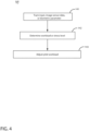
FIG. 4 is a flowchart illustrating a method of adjusting pilot workload during a flight of an aircraft ofFIG. 1 according to various aspects described herein. -
FIG. 5 is a flowchart illustrating another method of adjusting a planned pilot workload for an aircraft ofFIG. 1 before the planned flight according to various aspects described herein. - Aspects of the present disclosure are directed to a method of adjusting a pilot workload during a flight. As used herein, workload means the tasks a pilot must perform during various stages of the flight. During operation of an aircraft, portions of a flight plan such as takeoff, landing or even flying over certain geographic areas can require significant pilot attention and workload and in some cases can increase a pilot's stress level. Other portions of a flight plan, such as cruise during long flights, may need minimal pilot attention. It can be beneficial to track a pilot's workload or stress level during flight and adjust the pilot's workload when the pilot's stress level or workload exceeds a predetermined threshold.
- The present disclosure is also directed to a method of adjusting a pre-planned workload before a fight. Since flights often take place over the same flight path, such as from city-to-city, flight data can be collected that is representative of a typical flight. During any given flight, data representing a pilot's workload or stress level can be collected and correlated with portions of a flight plan such as takeoff, landing or flying over certain geographic areas. Statistical analysis of the data can determine when a pilot has experienced high workload volumes or high stress levels. The data can be saved and analyzed to understand when a pilot will likely experience increases in workload for a similar future planned flight. Prior to a future flight, it can be beneficial to understand when a pilot will likely experience higher workloads during the flight. In this scenario, it may be possible to adjust the expected pilot work load during heavy workload periods by shifting tasks during the heavy workload period to light workload periods. Moreover, understanding workloads during a flight can help airlines adjust crew rosters to adjust for workload conditions.
- For purposes of illustration, the present disclosure will be described in the context of a flight management system in an aircraft environment. It will be understood, however, that the disclosure is not so limited and may have general applicability in non-aircraft applications, such as other mobile applications.
- As used herein, "a set" can include any number of the respectively described elements, including only one element. All directional references (e.g., radial, axial, proximal, distal, upper, lower, upward, downward, left, right, lateral, front, back, top, bottom, above, below, vertical, horizontal, clockwise, counterclockwise, upstream, downstream, forward, aft, etc.) are only used for identification purposes to aid the reader's understanding of the present disclosure, and do not create limitations, particularly as to the position, orientation, or use of the disclosure. Connection references (e.g., attached, coupled, connected, and joined) are to be construed broadly and can include intermediate members between a collection of elements and relative movement between elements unless otherwise indicated. As such, connection references do not necessarily infer that two elements are directly connected and in fixed relation to one another. The exemplary drawings are for purposes of illustration only and the dimensions, positions, order, and relative sizes reflected in the drawings attached hereto can vary.
- As used herein, a "controller" can include at least one processor and memory. Non-limiting examples of the memory can include Random Access Memory (RAM), Read-Only Memory (ROM), flash memory, or one or more different types of portable electronic memory, such as discs, DVDs, CD-ROMs, etc., or any suitable combination of these types of memory. The processor can be configured to run any suitable programs or executable instructions designed to carry out various methods, functionality, processing tasks, calculations, or the like, to enable or achieve the technical operations or operations described herein. The program can include a computer program product that can include machine-readable media for carrying or having machine-executable instructions or data structures stored thereon. Such machine-readable media can be any available media, which can be accessed by a general purpose or special purpose computer or other machine with a processor. Generally, such a computer program can include routines, programs, objects, components, data structures, algorithms, etc., that have the technical effect of performing particular tasks or implement particular abstract data types.
-
FIG. 1 schematically illustrates anaircraft 10 according to various aspects described herein. One ormore propulsion engines 12 can be coupled to afuselage 14, acockpit 16 can be positioned in thefuselage 14, andwing assemblies 18 can extend outward from thefuselage 14. A plurality ofaircraft systems 20 that enable proper operation of theaircraft 10 can be included as well as a flight control computer 22 (or "computer" 22). While a commercial aircraft has been illustrated, it is contemplated that aspects of the disclosure can be used in any type of legacy aircraft, for example, without limitation, fixed-wing, rotating-wing, rocket, or personal aircraft. - The plurality of
aircraft systems 20 can reside within thecockpit 16, within an electronics andequipment bay 23, or in other locations throughout theaircraft 10 including that they can be associated with theengines 12.Such aircraft systems 20 can include but are not limited to: an electrical system, an oxygen system, hydraulics and/or pneumatics system, a fuel system, a propulsion system, navigation systems, flight controls, audio/video systems, an Integrated Vehicle Health Management (IVHM) system, and systems associated with the mechanical structure of theaircraft 10. A variety ofaircraft systems 20 have been illustrated for exemplary purposes and it will be understood that they are only a few of the systems that can be included in theaircraft 10. - A
data network 26 over which the plurality ofaircraft systems 20 can communicate with each other and provide information to a crew of theaircraft 10 can be included. For example, theaircraft systems 20 can output various information to aflight deck 30 located in acockpit 16 of theaircraft 10. - A
communication interface 40 can be located within theaircraft 10 and operably coupled to at least some of the plurality ofaircraft systems 20. Thecommunication interface 40 has been illustrated as being included in thecockpit 16. It is contemplated that thecommunication interface 40 can be located in other locations within theaircraft 10 including within the electronics andequipment bay 23. Although only onecommunication interface 40 has been illustrated, it is contemplated that theaircraft 10 can have multiple communication interfaces. Thecommunication interface 40 can be utilized for communication with other aircraft or aground station 31, such as by radio contact in a non-limiting example. In addition, thecommunication interface 40 can transmit or receive data, including audio or visual data as appropriate. - The
ground station 31 can be in communication with thedata network 26 orcommunication interface 40. Theground station 31 can have a processor and software and capabilities for uploading or downloading software or data to the aircraft. Theground station 31 might also capability to store, analyze, and manipulate flight data with data analysis or other statistical software. It should be recognized that theaircraft 10 might also have a computing system capable of storing, analyzing, and manipulating flight data with data analysis or other statistical software. -
FIG. 2 illustrates a portion of thecockpit 16 of theaircraft 10 and anexemplary flight deck 30 havingvarious instruments 50 and flight displays 52. A first pilot (herein, a "pilot") can be present in aseat 54 at the left side of thecockpit 16 and a second pilot (herein, a "co-pilot") can be present at the right side of thecockpit 16 in aseat 55 and theflight deck 30 can be located in front of the pilot and co-pilot and can provide the flight crew with information to aid in operating theaircraft 10. The flight displays 52 can include either primary flight displays or multi-function displays and can display a wide range of aircraft, flight, navigation, and other information used in the operation and control of theaircraft 10. Further, both thevarious instruments 50 and flight displays 52 of theflight deck 30 can provide one or more visual indicia indicative of a corresponding health condition of one or more of theaircraft systems 20. - The
instruments 50 and flight displays 52 can be laid out in any manner including having fewer or more instruments or displays. Further, the flight displays 52 need not be coplanar and need not be the same size. A touch screen display or touch screen surface can be included in theflight display 52 and may be used by one or more flight crew members, including the pilot and co-pilot, to interact with the systems of theaircraft 10. Such touch screen surface can take any suitable form including that of a liquid crystal display (LCD) and can use various physical or electrical attributes to sense inputs from the flight crew. It is contemplated that theflight display 52 can be dynamic and that one or morecursor control devices 56 and/or one or moremultifunction keyboards 58 can be included in thecockpit 16 and can be used by one or more flight crew members to interact with the systems of theaircraft 10. In this manner, theflight deck 30 can be considered a user interface for theaircraft systems 20 and theaircraft 10. - The
flight control computer 22 can be operably coupled to components of theaircraft 10 including theaircraft systems 20,instruments 50, flight displays 52, touch screen surfaces,cursor control devices 56,keyboards 58, etc. Theflight control computer 22 can receive inputs from any number ofaircraft systems 20 or software programs responsible for managing the acquisition and storage of data. Theflight control computer 22 can also be in the form of a controller, and can be connected with other controllers of theaircraft 10. Theflight control computer 22 can includememory 60 andprocessing units 62, which can be running any suitable programs to implement a graphical user interface (GUI) and operating system. Theflight control computer 22 can include or be associated with, any suitable number of individual microprocessors, power supplies, storage devices, interface cards, auto flight systems, flight management computers, and other standard components. Theflight control computer 22 can include or cooperate with any number of software programs (e.g., flight management programs) or instructions designed to carry out the various methods, process tasks, calculations, and control/display functions necessary for operation of theaircraft 10. - The
communication interface 40 can be communicably coupled to theflight control computer 22 or other processors of theaircraft 10 as well as any number of the plurality ofaircraft systems 20 to transfer information on and off theaircraft 10. Thecommunication interface 40 can include any desired communication mechanism capable of wirelessly linking with other systems and devices, such as by radio contact in a non-limiting example. For example, one of theaircraft systems 20 can be in the form of adistress tracker 21 configured to transmit a state of aircraft distress (for example, "normal," "abnormal," or "distressed"). - A pilot tracking system or
tracking system 100 is illustrated as being in communication with theflight control computer 22. It will be understood that thetracking system 100 can be hard wired to theflight control computer 22 or can communicate in any suitable manner with theflight control computer 22 including via wireless communication. Alternatively, thetracking system 100 can be included as a module within theflight control computer 22. - The
tracking system 100 can include at least oneimaging module 102 and at least oneaudio module 104. Theimaging module 102 can include animage sensor 103 configured to sense visual information about a pilot or co-pilot, such as rapid eye movement, eyes moving one direction or another, being open or closed, a direction of gaze, or a facial state such as eyebrows raised or lowered, by way of non-limiting examples and provide an output signal based thereon. An eye movement or body movement parameter can be stored by thetracking system 100 Theimaging module 102 or theflight control computer 22 can also be in signal communication with any of the flight displays 52, such as to display a visual indication based on the sensed visual information from theimaging module 102. - The
audio module 104 can include anaudio sensor 105 configured to sense audio information about a pilot or co-pilot, such as a language being spoken in thecockpit 16, a voice volume, slurred or altered speech, a speech pattern, or sounds that can occur due to pilot or co-pilot interaction with anaircraft system 20 such as striking theflight deck 30 or typing on themultifunction keyboard 58 and provide an output signal based thereon. Theaudio module 104 can also provide audio feedback or sound to the pilot or co-pilot, such as through speakers mounted within the cockpit or through headphones worn by the pilot or co-pilot. Further, theaudio module 104 can be in signal communication with theimaging module 102. For example, theimaging module 102 can provide an indication for transmission through theaudio module 104, such as spoken commands in a low-visibility environment within thecockpit 16. Theaudio module 104 can also provide a signal for transmission via theimaging module 102, such as a flashing light display or text-based indicator to be read by a pilot or co-pilot. - At least one
biometric sensor 106 configured to sense a biometric parameter of the pilot or co-pilot can be included in thetracking system 100. For example, abiometric sensor 106 positioned on thefirst seat 54 can be configured to sense or detect a heart rate, breathing rate, perspiration rate, or bodily motion of the pilot when the pilot is sitting in thefirst seat 54. Alternatively, thebiometric sensor 106 can be positioned on a wearable device such as a wrist strap or headband. In still another example, thebiometric sensor 106 can be in the form of an optical sensor, e.g. a camera that monitors the pilot or co-pilot. - In addition, a
seat tracking module 108 can control aseat distance 110 between thefirst seat 54 and theflight deck 30. While not shown, thesecond seat 55 can also include such aseat tracking module 108. Further, aseat belt sensor 112 can sense the position of aseat belt 70 on thefirst seat 54 or thesecond seat 55, such as theseat belt 70 being buckled or unbuckled. - A
haptic feedback generator 114 can be coupled or integrated with either or both of the first andsecond seats haptic feedback generator 114 can be configured to vibrate, such as a steady or varying vibration pattern, to provide feedback to the pilot or co-pilot. In a non-limiting example wherein theaircraft 10 is not level during flight in low-visibility conditions, thehaptic feedback generator 114 can vibrate on a right-hand portion or left-hand portion of theseat aircraft 10 for correct orientation when flying. - A
timer 115 can also be included in thetracking system 100 and is illustrated as being coupled to theflight deck 30. Thetimer 115 can be positioned anywhere within or outside of thecockpit 16. Thetimer 115 can be configured to track an elapsed time of an event or to provide an alarm or other indication at a predetermined time. Non-limiting examples where thetimer 115 can be utilized include tracking an elapsed time of flight, an elapsed time of a pilot interaction with an aircraft system 20 (such as updating flight records via the multifunction keyboard 58), tracking an elapsed sleep time, indicating a time for changing a flight direction, or indicating a wake time. - An
additional controller 120 having aprocessor 122 and amemory 124 can also be included in thetracking system 100. Thecontroller 120 is illustrated as being coupled to theflight deck 30 and in signal communication with any or all of theflight control computer 22,instruments 50, flight displays 52,memory 60, processingunit 62,imaging module 102,audio module 104,biometric sensor 106,seat tracking module 108,seat belt sensor 112,haptic feedback generator 114, ortimer 115. Dashed lines have been used to illustrate a portion of the signal connection between the above-described components. The lack of a dashed line for signal connections is done for clarity of the figures, and it will be understood that components not connected by a dashed line can nonetheless be in signal communication. -
FIG. 3 schematically illustrates components of thetracking system 100 in exemplary communicative connection, where aseparate controller 120 is shown in signal connection with the various modules and sensors described above. Alternatively, it will be understood that theflight control computer 22 can be utilized or that each module or any combination of modules can include their own controller, processor, or memory. Arrows have been included to indicate an exemplary signal or control direction, and are provided for clarity in discussion. It will be understood that any signal communication or control between connected components inFIG. 3 can be transmitted in either direction, and an arrow's illustrated direction does not imply a one-way signal or control direction. - A
door lock module 116 with adoor lock sensor 117 can further be included in thetracking system 100. For example, acockpit door 72 can include thedoor lock module 116 configured to sense whether thedoor 72 is locked or unlock. Themodule 116 can also automatically lock or unlock thedoor 72 based on a control signal within thetracking system 100. - The
controller 120 can be operably connected to and receive input from any or all of theflight control computer 22,image sensor 103,audio sensor 105,biometric sensor 106,seat tracking module 108,seat belt sensor 112,haptic feedback generator 114,timer 115, ordoor lock module 116. Any of the inputs received by thecontroller 120 can be stored in thememory 124. For example, thememory 124 can store a history of audio input or recordings from data gathered within thecockpit 16, or an elapsed time since a pilot last interacted with a flight display 52 (FIG. 2 ). - The
processor 122 of thecontroller 120 can send a signal or control command to any or all of theimaging module 102,audio module 104,seat tracking module 108,haptic feedback generator 114, ordoor lock module 116. In another non-limiting example, theprocessor 122 can send a signal to theimaging module 102, such as a visual message to be read by the pilot or co-pilot on theflight display 52, or a command to enable or disable theimage sensor 103. - It is further contemplated that the
controller 120 of thetracking system 100 can issue a signal or command to another aircraft system, such as thecommunication interface 40 via theflight control computer 22. In such a case, thecontroller 120 can communicate with an external aircraft or ground station (not shown). Thecontroller 120 can also be communicatively coupled with anyother aircraft system 20 as desired. - Referring now to
FIG. 4 , amethod 140 of adjusting pilot workflow during a flight is illustrated. Themethod 140 begins at 141 with tracking inputs by a pilot or trackingimage sensor 103 data or a biometric parameters of the pilot to determine a stress level of the pilot during flight of theaircraft 10 by using at least one sensor within thetracking system 100. The tracking of inputs, sensor data or biometric parameters can occur over distinct periods of time such as over an entire flight, or portions of a flight such as an elapsed time over a geographic location, an elapsed time a pilot has been on-board, or an elapsed time of a flight phase such as flight take off, flight landing or cruising. - Tracking inputs by the pilot can be an indication of the pilot's workload. For example, tracking pilot input can be accomplished via the
image sensor 103, such as visually detecting the pilot's hand interacting with thekeyboard 58 orflight display 52. In an example where theflight display 52 includes a touchscreen, thecontroller 120 can detect that the pilot has touched or interacted with thetouchscreen flight display 52. Tracking pilot input can also be accomplished via theflight control computer 22 which is communicatively coupled to thecontroller 120, including tracking that the pilot has interacted with or entered input to any cockpit system e.g. thekeyboard 58 or thecursor control device 56. - Tracking a pilot's stress level can be accomplished by tracking a pilot's eye movements or body movements from the
image sensor 103 or by tracking various biometric parameters of the pilot. For example, theimage sensor 103 can track both the eye movements and body movements of the pilot during all or portions of the flight. In addition, biometric parameters of the pilot such as heart rate, breathing rate, skin temperature, and the like, can be indicative of the pilot's stress level. It should be recognized that this data can be used to make real-time decisions about pilot workload or stress level during a flight or the data can be saved to a database and processed after the flight. - At 142, the
controller 120 can determine the workload or stress level of the pilot based on the tracked pilot input,image sensor 103 data, or biometric parameter(s) from 141. For example, thetimer 115 in conjunction with theflight control computer 22 can indicate to thecontroller 120 that the pilot has input multiple inputs into various avionics systems over a short period of time and is backed up onflight control computer 22 requests. Thecontroller 120 can then determine the rate at which the pilot is addressingflight control computer 22 requests and determine the workload level of the pilot. - The
controller 120 can also or alternatively determine, at 142, a stress level of the pilot basedimage sensor 103 data. For example, if the pilot's eyes are rapidly moving from screen to screen thecontroller 120 can determine the pilot stress level by correlating the movements with other real-time parameters, against pre-existing data, or above a predetermined threshold level. - Similarly, the
controller 120 can also or alternatively determine, at 142, a stress level of the pilot based on the biometric parameter. For example, thebiometric sensor 106 can determine a pilot's rate of breathing, heart rate, pulse rate, and the like. Thecontroller 120 can determine the pilot stress level by correlating any of the biometrics parameters with other real-time parameters such as data from theimage sensor 103, against pre-existing data, or above a predetermined threshold level. - At 143, the
controller 120 can adjust the pilot workload during flight when one of the pilot workload or pilot stress level exceeds a predetermined threshold. For example, if thecontroller 120 determines that the pilot's stress level is above a predetermined threshold value based on sensor readings from one of theimage sensor 103 orbiometric sensor 106 then thecontroller 120 can be programmed to shift certain tasks such as non-critical or non-essential pilot tasks to the co-pilot or other crew member. In addition or alternatively, thecontroller 120 can be programmed to shift the non-critical or non-essential pilot tasks to a future time frame when the pilot has less tasks in his workload. - Turning to
FIG. 5 , amethod 150 of adjusting a planned pilot workload before the planned flight is shown. The method includes, at 151, tracking inputs by a pilot, or trackingimage sensor 103 data, or a biometric parameter of the pilot during flight of theaircraft 10 during one or more aircraft flights. Since flights often take place over the same flight path, such as from city-to-city, flight data can be collected that is representative of a typical flight between the two cities. At this step, it is contemplated that data can be tracked and collected from multiple flights over various time frames and preferably from flights that fly the same or similar flight paths. The data can be tracked, collected, and analyzed to understand time frames during a flight that pilot's experience heavy workloads and high stress. The data processing can be done on or offaircraft 10, where theflight control computer 22 or other processors on theaircraft 10 can adjust the expected pilot workload before the planned flight. - At 152, data from the
image sensor 103, biometric sensor 106 (i.e. biometric parameters), and pilot inputs responsive to theflight control computer 22 can be correlated with one or more time periods of the flight. In other words, at thisstep 152, for any given flight, data representing a pilot's workload or stress level can be collected and correlated over distinct periods of time such as over an entire flight, or portions of a flight such as an elapsed time over a geographic location, an elapsed time a pilot has been on-board, or an elapsed time of a flight phase such as flight take off, flight landing or cruising. In this example, thetimer 115 can track the time of flight which can be correlated with the collected pilot data across the all or a portion of the flight. Data from each recorded flight can be stored onboard or can be transmitted offsite to aground station 31 for analysis and processing. - At 154, analysis of the data, either on-aircraft by an on-board processor or offsite by the ground station, can identify which of the time periods the pilot's workload was above a predetermined threshold value indicative of a pilot experiencing high workload volumes or high stress levels. In one example, data from multiple independent flights with similar flight paths can be analyzed to understand specific time frames the pilots of each of flights experienced high workload volumes or stress levels. Using this data, the
controller 120 or other processor can predict when a pilot on a planned flight will likely experience increases in workload or higher stress levels. - At 156, prior to a planned flight, the
controller 120 or other processer that is operatively connected to the flight control computer can adjust the expected pilot work load during the planned flight. In this scenario, thecontroller 120 or other processer can predict heavy workload periods in the planned flight and can adjust the pilot workload by shifting tasks from the predicted heavy workload period to periods where the pilot workload if predicted to be light. Moreover, thecontroller 120 or other process can predict when work load will be heavy for the entire crew and can predict when additional or less crew may be required for certain flights or certain conditions. - To the extent not already described, the different features and structures of the various embodiments can be used in combination, or in substitution with each other as desired. That one feature is not illustrated in all of the embodiments is not meant to be construed that it cannot be so illustrated, but is done for brevity of description. Thus, the various features of the different embodiments can be mixed and matched as desired to form new embodiments, whether or not the new embodiments are expressly described. All combinations or permutations of features described herein are covered by this disclosure.
- This written description uses examples to disclose the invention, including the best mode, and also to enable any person skilled in the art to practice the invention, including making and using any devices or systems and performing any incorporated methods. The patentable scope of the invention is defined by the claims, and may include other examples that occur to those skilled in the art. Such other examples are intended to be within the scope of the claims if they have structural elements that do not differ from the literal language of the claims, or if they include equivalent structural elements with insubstantial differences from the literal languages of the claims.
- Further aspects of the invention are provided by the subject matter of the following clauses:
- 1. A method of adjusting an operator workload during a travel segment, the method comprising: tracking over a time period, using at least one sensor, one of inputs by an operator indicative of an operator workload or image sensor data or a biometric parameter indicative of an operator stress level during the travel segment, determining, using a controller that is operatively connected to the at least one sensor, a level of one of the operator workload or operator stress level, and adjusting, using a controller that is operatively connected to the control computer, the operator workload when the level of one of the operator workload or operator stress level exceeds a predetermined threshold.
- 2. The method of any preceding clause wherein the operator is a pilot and the travel segment is a flight.
- 3.The method of any preceding clause wherein the time period comprises one of elapsed time over a geographic location, an elapsed time a pilot has been on-board, or an elapsed time of a flight phase.
- 4.The method of any preceding clause wherein flight phase comprises one of flight take off, flight landing, or cruising.
- 5.The method of any preceding clause wherein the image sensor data is indicative of one of an operator's eye movements or body movements.
- 6.The method of any preceding clause wherein the biometric parameter is based on one of an operator's breathing, heart rate, or pulse rate.
- 7.The method of any preceding clause wherein the image sensor data and biometric parameters are stored as data in a database.
- 8.The method of any preceding clause further comprising correlating one of the image sensor data or biometric parameters with the time period for analysis.
- 9.The method of any preceding clause further comprising identifying time periods of higher operator workloads by comparing inputs by an operator over a time period against a predetermined threshold.
- 10.The method of any preceding clause wherein identifying time periods of higher operator workloads occurs real-time during the travel segment.
- 11.The method of any preceding clause wherein the identifying time periods of higher operator workloads occurs after the travel segment has ended.
- 12. A method of adjusting a planned pilot workload before the planned flight, the method comprising: tracking over a time period, using at least one sensor, inputs by a pilot indicative of a pilot workload or image sensor data or a biometric parameter indicative of a pilot stress level during one or more flights of an aircraft prior to the assigned flight, correlating, using a controller that is operatively connected to the at least one sensor, one of the image sensor data, biometric parameters or pilot workload with one or more time periods for analysis, identifying, using a processor that is operatively connected to a controller, which of the one or more time periods comprise pilot workload above a threshold value based on the analysis, adjusting, using a controller that is operatively connected to the flight control computer, the pilot workload during the time periods above the threshold value of pre-planned pilot workload of the assigned flight.
- 13.The method of any preceding clause wherein the time period comprises one of elapsed time over a geographic location, an elapsed time a pilot has been on-board, or an elapsed time of a flight phase.
- 14.The method of any preceding clause wherein flight phase comprises one of flight take off, flight landing, or cruising.
- 15. The method of any preceding clause wherein the identifying time periods of higher pilot workloads comprises comparing inputs by a pilot over a time period against a predetermined threshold.
- 16.The method of any preceding clause wherein the identifying time periods of higher pilot workloads occurs after a flight has ended.
- 17.The method of any preceding clause wherein the adjusting the pilot workload comprises moving one or more pilot tasks of the flight control controller to a different time period.
- 18.The method of any preceding clause wherein the step of adjusting the pilot workload comprises adjusting crew roster for accommodating pilot workload.
- 19.The method of any preceding clause wherein the image sensor data is indicative of one of a pilot's eye movements or body movements.
- 20.The method of any preceding clause wherein the biometric parameter is based on one of a pilot's breathing, heart rate, or pulse rate.
Claims (11)
- A method of adjusting an operator workload during a travel segment, the method comprising:tracking, over a time period, inputs by an operator into an avionic system responsive to a request from a flight control computer during one or more flights of an aircraft, during the travel segment;determining a rate at which the inputs by the operator are made;determining an operator workload based on the rate at which the inputs by the operator are made; andadjusting, using a controller that is operatively connected to the flight control computer, the operator workload when the operator workload exceeds a predetermined threshold.
- The method of claim 1, wherein the operator is a pilot and the travel segment is a flight.
- The method of claim 2, wherein the time period comprises one of elapsed time over a geographic location, an elapsed time the pilot has been on-board, or an elapsed time of a flight phase.
- The method of claim 2 or claim 3, wherein flight phase comprises one of flight take off, flight landing, or cruising.
- The method of any of claims 1-4, wherein the rate at which the inputs by the operator are made is stored as data in a database.
- The method of claim 5, further comprising correlating the rate at which the inputs by the operator are made with the time period.
- The method of claim 6, further comprising identifying a time period of higher operator workload by comparing the rate at which the inputs by the operator are made over a time period against a predetermined threshold.
- The method of claim 7, wherein the identifying time periods of higher operator workloads occurs real-time during the travel segment.
- The method of claim 7, wherein the identifying time periods of higher operator workloads occurs after the travel segment has ended.
- The method of any of claims 1-9, wherein the adjusting the operator workload comprises moving one or more operator tasks by the controller to a different time period.
- The method of any of claims 1-10, wherein the adjusting the operator workload comprises adjusting a crew roster to accommodate the operator workload.
Applications Claiming Priority (2)
| Application Number | Priority Date | Filing Date | Title |
|---|---|---|---|
| GB1820118.6A GB2579775B (en) | 2018-12-11 | 2018-12-11 | Aircraft and method of adjusting a pilot workload |
| EP19214150.5A EP3667645B1 (en) | 2018-12-11 | 2019-12-06 | Aircraft and method of adjusting a pilot workload |
Related Parent Applications (2)
| Application Number | Title | Priority Date | Filing Date |
|---|---|---|---|
| EP19214150.5A Division-Into EP3667645B1 (en) | 2018-12-11 | 2019-12-06 | Aircraft and method of adjusting a pilot workload |
| EP19214150.5A Division EP3667645B1 (en) | 2018-12-11 | 2019-12-06 | Aircraft and method of adjusting a pilot workload |
Publications (2)
| Publication Number | Publication Date |
|---|---|
| EP4459233A2 true EP4459233A2 (en) | 2024-11-06 |
| EP4459233A3 EP4459233A3 (en) | 2025-02-12 |
Family
ID=65030007
Family Applications (2)
| Application Number | Title | Priority Date | Filing Date |
|---|---|---|---|
| EP19214150.5A Active EP3667645B1 (en) | 2018-12-11 | 2019-12-06 | Aircraft and method of adjusting a pilot workload |
| EP24200033.9A Pending EP4459233A3 (en) | 2018-12-11 | 2019-12-06 | Aircraft and method of adjusting a pilot workload |
Family Applications Before (1)
| Application Number | Title | Priority Date | Filing Date |
|---|---|---|---|
| EP19214150.5A Active EP3667645B1 (en) | 2018-12-11 | 2019-12-06 | Aircraft and method of adjusting a pilot workload |
Country Status (4)
| Country | Link |
|---|---|
| US (2) | US11928970B2 (en) |
| EP (2) | EP3667645B1 (en) |
| CN (1) | CN111311051A (en) |
| GB (1) | GB2579775B (en) |
Families Citing this family (8)
| Publication number | Priority date | Publication date | Assignee | Title |
|---|---|---|---|---|
| WO2022019826A1 (en) * | 2020-07-20 | 2022-01-27 | Hitachi, Ltd. | Scheduling system, methods of operating and forming the same |
| FR3117631B1 (en) * | 2020-12-15 | 2024-11-29 | Dassault Aviat | System for determining an operational state of an aircraft crew based on an adaptive task plan and associated method |
| FR3126517B1 (en) * | 2021-08-31 | 2024-09-20 | Thales Sa | SYSTEM FOR ASSISTING IN TAKING INTO ACCOUNT FEEDBACK CONCERNING A PREVIOUS ACTION OF A USER; ASSOCIATED METHOD AND COMPUTER PROGRAM PRODUCT |
| US12555052B2 (en) | 2022-01-19 | 2026-02-17 | Honeywell International Inc. | System for vehicle operator workload assessment and annunciation |
| CN114200962B (en) * | 2022-02-15 | 2022-05-17 | 四川腾盾科技有限公司 | Unmanned aerial vehicle flight task execution condition analysis method |
| US20230297123A1 (en) * | 2022-03-17 | 2023-09-21 | Honeywell International Inc. | Multimodal pilot monitoring methods and systems |
| EP4324749B1 (en) * | 2022-08-17 | 2025-10-29 | Airbus (S.A.S.) | Vehicle operator monitoring method and system |
| US20250259549A1 (en) * | 2024-02-09 | 2025-08-14 | Fly Hangar, LLC | Systems and methods for flight data content generation |
Family Cites Families (53)
| Publication number | Priority date | Publication date | Assignee | Title |
|---|---|---|---|---|
| US5900827A (en) | 1988-06-07 | 1999-05-04 | The Boeing Company | Flight crew response monitor |
| US5243339A (en) | 1988-06-07 | 1993-09-07 | The Boeing Company | Flight crew response monitor |
| US6070098A (en) | 1997-01-11 | 2000-05-30 | Circadian Technologies, Inc. | Method of and apparatus for evaluation and mitigation of microsleep events |
| US7664601B2 (en) * | 1999-11-10 | 2010-02-16 | Honeywell International Inc. | Weather incident prediction |
| US7383283B2 (en) * | 2001-10-16 | 2008-06-03 | Joseph Carrabis | Programable method and apparatus for real-time adaptation of presentations to individuals |
| EP1619997A4 (en) * | 2003-05-06 | 2008-07-23 | Univ Pittsburgh | APPARATUS AND METHOD FOR POSTURAL EXAMINATION COMPLETELY FOR REALIZING COGNITIVE TASKS |
| DE10322458A1 (en) * | 2003-05-16 | 2004-12-02 | Daimlerchrysler Ag | Method and device for influencing the stress of a driver in a motor vehicle |
| US8164464B2 (en) | 2005-03-24 | 2012-04-24 | Matos Jeffrey A | Method and system of aircraft pilot assessment |
| US7301464B2 (en) | 2005-05-24 | 2007-11-27 | Electronic Data Systems Corporation | Process and method for safer vehicle navigation through facial gesture recognition and operator condition monitoring |
| US7437225B1 (en) | 2005-07-29 | 2008-10-14 | Rockwell Collins, Inc. | Flight management system |
| FR2906048B1 (en) * | 2006-09-19 | 2008-12-19 | Thales Sa | METHOD AND DEVICE FOR MODIFYING A FLIGHT PLAN AND IN PARTICULAR A TAKE-OFF PROCEDURE FOR AN AIRCRAFT |
| FR2922642B1 (en) * | 2007-10-19 | 2010-01-22 | Airbus France | METHOD AND DEVICE FOR CREATING A FLIGHT PLAN OF AN AIRCRAFT |
| US20110102570A1 (en) * | 2008-04-14 | 2011-05-05 | Saar Wilf | Vision based pointing device emulation |
| US8200379B2 (en) | 2008-07-03 | 2012-06-12 | Manfredi Dario P | Smart recovery system |
| US20100106346A1 (en) * | 2008-10-23 | 2010-04-29 | Honeywell International Inc. | Method and system for managing flight plan data |
| KR101173944B1 (en) | 2008-12-01 | 2012-08-20 | 한국전자통신연구원 | System and method for controlling sensibility of driver |
| US8514104B1 (en) * | 2009-06-12 | 2013-08-20 | Rockwell Collins, Inc. | Integrated minimum equipment decision support system |
| US20120116186A1 (en) | 2009-07-20 | 2012-05-10 | University Of Florida Research Foundation, Inc. | Method and apparatus for evaluation of a subject's emotional, physiological and/or physical state with the subject's physiological and/or acoustic data |
| US20110118908A1 (en) * | 2009-11-18 | 2011-05-19 | The Boeing Company | Methods and systems for management of airplane speed profile |
| US8552850B2 (en) | 2010-02-17 | 2013-10-08 | Honeywell International Inc. | Near-to-eye tracking for adaptive operation |
| CN103003854B (en) * | 2010-07-29 | 2015-05-27 | 福特全球技术公司 | Systems and methods for scheduling driver interface tasks based on driver workload |
| US8972106B2 (en) * | 2010-07-29 | 2015-03-03 | Ford Global Technologies, Llc | Systems and methods for scheduling driver interface tasks based on driver workload |
| US20120075122A1 (en) | 2010-09-24 | 2012-03-29 | Honeywell International Inc. | Alert generation and related aircraft operating methods |
| US8928498B2 (en) * | 2010-09-27 | 2015-01-06 | Honeywell International Inc | Workload management system and method |
| US20120075123A1 (en) * | 2010-09-29 | 2012-03-29 | Honeywell International Inc. | Dynamic task and adaptive avionics display manager |
| US20120256749A1 (en) * | 2011-04-11 | 2012-10-11 | Ford Global Technologies, Llc | Method and Apparatus for Health Monitoring |
| US8766819B2 (en) * | 2011-06-17 | 2014-07-01 | The Boeing Company | Crew allertness monitoring of biowaves |
| US9380978B2 (en) * | 2011-06-29 | 2016-07-05 | Bruce Reiner | Method and apparatus for real-time measurement and analysis of occupational stress and fatigue and performance outcome predictions |
| US9124955B2 (en) * | 2011-09-19 | 2015-09-01 | Card Guard Scientific Survival Ltd. | Vehicle driver monitor and a method for monitoring a driver |
| US20140343765A1 (en) * | 2012-12-28 | 2014-11-20 | Sean Patrick Suiter | Flight Assistant with Automatic Configuration and Landing Site Selection |
| US8988524B2 (en) * | 2013-03-11 | 2015-03-24 | The United States Of America As Represented By The Secretary Of The Army | Apparatus and method for estimating and using a predicted vehicle speed in an indirect vision driving task |
| US9446852B2 (en) | 2013-09-18 | 2016-09-20 | Honeywell International Inc. | Aircraft systems and methods for detecting non-compliant pilot action |
| CA2969552A1 (en) * | 2013-12-04 | 2015-06-11 | Spatial Information Systems Research Limited | Method and apparatus for developing a flight path |
| US9227736B2 (en) | 2014-03-07 | 2016-01-05 | Honeywell International Inc. | Methods and apparatus for determining pilot awareness of a system-initiated change based on scanning behavior |
| US20150302653A1 (en) * | 2014-04-22 | 2015-10-22 | Cherif Atia Algreatly | Augmented Digital Data |
| EP3177204A1 (en) | 2014-09-09 | 2017-06-14 | Torvec, Inc. | Methods and apparatus for monitoring alertness of an individual utilizing a wearable device and providing notification |
| US9697737B2 (en) * | 2014-09-30 | 2017-07-04 | The Boeing Company | Automatic real-time flight plan updates |
| US9472106B2 (en) * | 2014-09-30 | 2016-10-18 | The Boeing Company | Automated flight object procedure selection system |
| GB2535544B (en) * | 2015-02-23 | 2018-10-03 | Jaguar Land Rover Ltd | Display control apparatus and method |
| US9919712B1 (en) | 2015-08-10 | 2018-03-20 | Rockwell Collins, Inc. | Crew biometrics and aircraft data analysis with real-time and proactive actions |
| US9637133B1 (en) | 2015-08-10 | 2017-05-02 | Rockwell Collins, Inc. | Operator capacity monitor and engagement of emergency action system and method |
| US9701418B2 (en) | 2015-10-06 | 2017-07-11 | Honeywell International Inc. | Pilot fatigue detection system and method from aircraft control device movement |
| US20170115124A1 (en) * | 2015-10-21 | 2017-04-27 | Ford Global Technologies, Llc | Driver Workload Prediction and Path Routing |
| US9786189B2 (en) * | 2016-01-25 | 2017-10-10 | Sikorsky Aircraft Corp. | Aircraft control systems |
| KR101663922B1 (en) | 2016-01-26 | 2016-10-14 | 이호석 | Apparatus and method for monitoring condition of pilot |
| US10065658B2 (en) * | 2016-05-23 | 2018-09-04 | International Business Machines Corporation | Bias of physical controllers in a system |
| US10216186B2 (en) * | 2016-05-23 | 2019-02-26 | Sikorsky Aircraft Corporation | Task allocation and variable autonomy levels |
| CN109716411B (en) * | 2016-09-08 | 2021-06-25 | 福特汽车公司 | Method and apparatus for monitoring driver's activity level |
| GB2559606B (en) * | 2017-02-13 | 2021-03-10 | Jaguar Land Rover Ltd | Controlling the operation of a head-up display apparatus |
| US10816970B2 (en) * | 2017-06-15 | 2020-10-27 | Aurora Flight Sciences Corporation | System and method for performing an emergency descent and landing |
| US10556703B1 (en) * | 2017-06-21 | 2020-02-11 | Rockwell Collins, Inc. | Predictive aircraft performance systems and methods |
| US10426393B2 (en) * | 2017-09-22 | 2019-10-01 | Aurora Flight Sciences Corporation | Systems and methods for monitoring pilot health |
| US20190340935A1 (en) * | 2018-05-03 | 2019-11-07 | Honeywell International Inc. | Aircraft navigation system for free route airspace |
-
2018
- 2018-12-11 GB GB1820118.6A patent/GB2579775B/en active Active
-
2019
- 2019-12-06 EP EP19214150.5A patent/EP3667645B1/en active Active
- 2019-12-06 EP EP24200033.9A patent/EP4459233A3/en active Pending
- 2019-12-09 CN CN201911249610.4A patent/CN111311051A/en active Pending
- 2019-12-10 US US16/709,409 patent/US11928970B2/en active Active
-
2024
- 2024-02-16 US US18/443,835 patent/US12494134B2/en active Active
Also Published As
| Publication number | Publication date |
|---|---|
| GB2579775B (en) | 2022-02-23 |
| EP3667645B1 (en) | 2024-10-30 |
| CN111311051A (en) | 2020-06-19 |
| US20200184833A1 (en) | 2020-06-11 |
| EP4459233A3 (en) | 2025-02-12 |
| GB2579775A (en) | 2020-07-08 |
| US20240185726A1 (en) | 2024-06-06 |
| GB201820118D0 (en) | 2019-01-23 |
| EP3667645A1 (en) | 2020-06-17 |
| US11928970B2 (en) | 2024-03-12 |
| US12494134B2 (en) | 2025-12-09 |
Similar Documents
| Publication | Publication Date | Title |
|---|---|---|
| US12494134B2 (en) | System and method of adjusting a pilot workload | |
| US11810400B2 (en) | Method of assessing a pilot emotional state | |
| US10426393B2 (en) | Systems and methods for monitoring pilot health | |
| US12168513B2 (en) | Mitigating operational risk in aircraft | |
| EP3415416B1 (en) | Aircrew automation system | |
| US12013692B2 (en) | Aircraft and method of controlling | |
| KR102269419B1 (en) | Crew automation systems and methods | |
| US8766819B2 (en) | Crew allertness monitoring of biowaves | |
| US20230297123A1 (en) | Multimodal pilot monitoring methods and systems | |
| US10328852B2 (en) | Systems and methods to provide feedback to pilot/operator by utilizing integration of navigation and physiological monitoring | |
| EP4246494A1 (en) | Multimodal pilot monitoring methods and systems | |
| GB2604716A (en) | Aircraft and method of adjusting a pilot workload | |
| GB2609873A (en) | Aircraft and method of controlling | |
| Nagel et al. | Human Error |
Legal Events
| Date | Code | Title | Description |
|---|---|---|---|
| PUAI | Public reference made under article 153(3) epc to a published international application that has entered the european phase |
Free format text: ORIGINAL CODE: 0009012 |
|
| STAA | Information on the status of an ep patent application or granted ep patent |
Free format text: STATUS: THE APPLICATION HAS BEEN PUBLISHED |
|
| AC | Divisional application: reference to earlier application |
Ref document number: 3667645 Country of ref document: EP Kind code of ref document: P |
|
| AK | Designated contracting states |
Kind code of ref document: A2 Designated state(s): AL AT BE BG CH CY CZ DE DK EE ES FI FR GB GR HR HU IE IS IT LI LT LU LV MC MK MT NL NO PL PT RO RS SE SI SK SM TR |
|
| REG | Reference to a national code |
Ref country code: DE Ref legal event code: R079 Free format text: PREVIOUS MAIN CLASS: G01C0023000000 Ipc: G08G0005000000 |
|
| PUAL | Search report despatched |
Free format text: ORIGINAL CODE: 0009013 |
|
| AK | Designated contracting states |
Kind code of ref document: A3 Designated state(s): AL AT BE BG CH CY CZ DE DK EE ES FI FR GB GR HR HU IE IS IT LI LT LU LV MC MK MT NL NO PL PT RO RS SE SI SK SM TR |
|
| RIC1 | Information provided on ipc code assigned before grant |
Ipc: G06F 3/01 20060101ALI20250109BHEP Ipc: A61B 5/00 20060101ALI20250109BHEP Ipc: A61B 5/18 20060101ALI20250109BHEP Ipc: A61B 5/16 20060101ALI20250109BHEP Ipc: G06F 3/00 20060101ALI20250109BHEP Ipc: G01C 23/00 20060101ALI20250109BHEP Ipc: G08G 5/00 20060101AFI20250109BHEP |
|
| STAA | Information on the status of an ep patent application or granted ep patent |
Free format text: STATUS: REQUEST FOR EXAMINATION WAS MADE |
|
| 17P | Request for examination filed |
Effective date: 20250723 |
|
| STAA | Information on the status of an ep patent application or granted ep patent |
Free format text: STATUS: EXAMINATION IS IN PROGRESS |
|
| 17Q | First examination report despatched |
Effective date: 20260211 |