EP4459200A1 - Heat exchange unit, and refrigeration cycle device - Google Patents
Heat exchange unit, and refrigeration cycle device Download PDFInfo
- Publication number
- EP4459200A1 EP4459200A1 EP22933467.7A EP22933467A EP4459200A1 EP 4459200 A1 EP4459200 A1 EP 4459200A1 EP 22933467 A EP22933467 A EP 22933467A EP 4459200 A1 EP4459200 A1 EP 4459200A1
- Authority
- EP
- European Patent Office
- Prior art keywords
- elastically deformable
- deformable portion
- lid
- electric components
- components box
- Prior art date
- Legal status (The legal status is an assumption and is not a legal conclusion. Google has not performed a legal analysis and makes no representation as to the accuracy of the status listed.)
- Pending
Links
Images





Classifications
-
- F—MECHANICAL ENGINEERING; LIGHTING; HEATING; WEAPONS; BLASTING
- F25—REFRIGERATION OR COOLING; COMBINED HEATING AND REFRIGERATION SYSTEMS; HEAT PUMP SYSTEMS; MANUFACTURE OR STORAGE OF ICE; LIQUEFACTION SOLIDIFICATION OF GASES
- F25B—REFRIGERATION MACHINES, PLANTS OR SYSTEMS; COMBINED HEATING AND REFRIGERATION SYSTEMS; HEAT PUMP SYSTEMS
- F25B49/00—Arrangement or mounting of control or safety devices
- F25B49/02—Arrangement or mounting of control or safety devices for compression type machines, plants or systems
-
- F—MECHANICAL ENGINEERING; LIGHTING; HEATING; WEAPONS; BLASTING
- F24—HEATING; RANGES; VENTILATING
- F24F—AIR-CONDITIONING; AIR-HUMIDIFICATION; VENTILATION; USE OF AIR CURRENTS FOR SCREENING
- F24F1/00—Room units for air-conditioning, e.g. separate or self-contained units or units receiving primary air from a central station
- F24F1/06—Separate outdoor units, e.g. outdoor unit to be linked to a separate room comprising a compressor and a heat exchanger
- F24F1/20—Electric components for separate outdoor units
- F24F1/22—Arrangement or mounting thereof
Definitions
- the present disclosure relates to a heat exchange unit, and a refrigeration cycle device.
- an air conditioning device that includes an electronic unit, the electronic unit having a sealing material that seals a space between a case main body (electric components box main body) and a case cover (cover main body) provided is known.
- Patent Document 1 Japanese Unexamined Application No. 10-220824 , First Publication
- the present disclosure has been made in order to address the problem above, and an object is to provide a heat exchange unit having a construction where a degradation in sealing ability is suppressed, and a refrigeration cycle device that includes such heat exchange unit.
- An embodiment of a heat exchange unit which is a heat exchange unit of a refrigeration cycle device according to the present disclosure includes: a housing; a heat exchanger housed on an inside of the housing; a blower housed on the inside of the housing, and an electric components box housed on the inside of the housing, wherein the electric components box has an electric components box main body having an opening that opens to a first side in a first direction, and a lid that plugs the opening, and is fixed to the electric components box main body, an elastically deformable portion that is elastically deformable in the first direction, is formed on an edge of the opening, the elastically deformable portion directly or indirectly contacts the lid, in a state where the elastically deformable portion is elastically deformed to a second side that is opposite to the first side in the first direction, and a force is applied to the lid in the first side direction.
- a refrigeration cycle device includes an outdoor unit, and an indoor unit, wherein the outdoor unit or the indoor unit is the heat exchange unit mentioned above.
- the drawings show an X axis, a Y axis, and a Z axis where appropriate.
- the X axis shows a side out of sides of a horizontal direction.
- the Y axis shows another side out of sides of the horizontal direction.
- the Z axis shows a vertical direction.
- a horizontal direction along the X axis is referred to as a "front-rear direction X”
- a horizontal direction along the Y axis is referred to as a "left-right direction Y”.
- a vertical direction is referred to as a "vertical direction Z”.
- the front-rear direction X, the left-right direction Y, and the vertical direction Z are mutually orthogonal directions.
- a side out of sides of the vertical direction Z in which an arrow of the Z axis faces is a top side (+Z side).
- the other side out of sides of the vertical direction Z which faces an opposite side the arrow of the Z axis faces is a bottom side (-Z side).
- a side out of sides of the front-rear direction X in which an arrow of the X axis faces is a front side (+X side).
- a side out of sides of the front-rear direction X which faces an opposite side the arrow of the X axis faces is a rear side (-X side).
- the left-right direction Y in the embodiment below, is the left-right direction Y in a case where an outdoor unit 10 is viewed from the front side (+X side).
- a side out of sides of the left-right direction Y in which an arrow of the Y axis faces is a right side (+Y side).
- a side out of sides in the left-right direction Y which faces an opposite side the arrow of the Y axis faces is a left side (-Y side).
- the vertical direction Z corresponds to a "first direction”.
- the top side corresponds to a "first side” in the first direction.
- the bottom side corresponds to a "second side", a side that is opposite to the first side in the first direction.
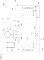
- FIG. 1 is a schematic view that shows an outline configuration of a refrigeration cycle device 100 in a first embodiment.
- the refrigeration cycle device 100 is a device that uses a refrigeration cycle in which a refrigerant 19 is circulated.
- the refrigeration cycle device 100 in the embodiment is an air conditioner.
- the refrigeration cycle device 100 includes the outdoor unit 10, an indoor unit 20, and a circulation path 18.
- the outdoor unit 10 is disposed outdoors.
- the indoor unit 20 is disposed indoors.
- the outdoor unit 10 and the indoor unit 20 are connected by the circulation path 18 that circulates a refrigerant 19.
- the outdoor unit 10 and the indoor unit 20 are heat exchange units that conduct heat exchange with air.
- a refrigerant such as a fluorine based refrigerant with a low global warming potential (GWP: Global Warming Potential), or a hydrocarbon based refrigerant or the like may be mentioned as examples of the refrigerant 19.
- GWP Global Warming Potential
- a density of the refrigerant 19 in a gaseous state is larger than a density of air.
- the fluorine based refrigerant with a low global warming potential is for example, HFC32.
- An example of the hydrocarbon based refrigerant is R290 (propane). Both the fluorine based refrigerant and the hydrocarbon based refrigerant are flammable refrigerants.
- the outdoor unit 10 includes a housing 11, a compressor 12, a heat exchanger 13, a flow adjustment valve 14, a blower 15, a four-way valve 16, a refrigerant pipe 18a, and a control unit 30.
- the compressor 12, the heat exchanger 13, the flow adjustment valve 14, the blower 15, the four-way valve 16, the refrigerant pipe 18a and the control unit 30 are housed on an inside of the housing 11.
- the four-way valve 16 is provided on a part that is connected to a discharge side of the compressor 12. By exchanging a portion of the circulation pathway 18, it is possible for the four-way valve 16 to reverse a direction of flow of the refrigerant 19 within the circulation pathway 18.
- the path connected by the four-way valve 16 is the path of the four-way valve 16 that is shown by solid lines in FIG. 1
- the refrigerant 19 within the circulation pathway 18 flows in the direction shown by the solid line arrow in FIG. 1 .
- the path connected by the four-way valve 16 is the path of the four-way valve 16 that is shown by dashed lines in FIG. 1
- the refrigerant 19 flows within the circulation pathway 18 in the direction shown by the dashed line arrow in FIG. 1 .
- the refrigerant pipe 18a is a pipe that configures a portion of the circulation pathway 18.
- the refrigerant pipe 18a is connected to a pipe that extends from the indoor unit 20.
- a plurality of refrigerant pipes 18a are provided on an inside of the housing 11 of the outdoor unit 10.
- the indoor unit 20 includes a housing 21, a heat exchanger 22, a blower 23, and a controller 24.
- the housing 21 houses the heat exchanger 22, the blower 23, and the controller 24 on an inside thereof. It is possible for the indoor unit 20 to have a cooling operation where the air of the room the indoor unit 20 is disposed in is cooled, and to have a heating operation where the air of the room the indoor unit 20 is disposed in is heated.
- the refrigerant 19 that flows within the circulation pathway 18 flows in the direction shown by solid lines in FIG. 1 .
- the refrigerant 19 that flows within the circulation pathway 18 circulates so as to return to the compressor 12 after passing through the compressor 12, the heat exchanger 13 of the outdoor unit 10, the flow adjustment valve 14, and the heat exchanger 22 of the indoor unit 20 in such an order.
- the heat exchanger 13 of the outdoor unit 10 functions as a condenser
- the heat exchanger 22 of the indoor unit 20 functions as an evaporator.
- the refrigerant 19 that flows within the circulation pathway 18 flows in the direction shown by dashed lines in FIG. 1 .
- the refrigerant 19 that flows within the circulation pathway 18 circulates so as to return to the compressor 12 after passing through the compressor 12, the heat exchanger 22 of the indoor unit 20, the flow adjustment valve 14, and the heat exchanger 13 on an inside of the outdoor unit 10 in such an order.
- the heat exchanger 13 of the outdoor unit 10 functions as the evaporator
- the heat exchanger 22 on an inside of the indoor unit 20 functions as the condenser.
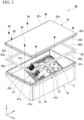
- FIG. 2 is a perspective view that shows a portion of the outdoor unit 10.
- the housing 11 has a blower room 11a and a mechanical room 11b that are partitioned from one another by a partition member 11c.
- the partition member 11c extends in the vertical direction Z.
- a plate surface of the partition member 11c is a semi-rectangular plate that faces the left-right direction Y.
- a top end of the partition member 11c is separately disposed to the bottom side, from a ceiling surface panel of the housing 11 that is not shown on the drawings.
- the ceiling surface panel not shown on the drawings is a wall portion located on the top side out of wall portions that configure the housing 11.
- the blower room 11a and the mechanical room 11b are adjacently disposed in the left-right direction Y.
- a dimension of the blower room 11a in the left-right direction Y is larger than a dimension of the mechanical room 11b in the left-right direction Y.
- the blower room 11a is located on the left side of the mechanical room 11b.
- a heat exchanger 13 and the blower 15 are disposed on an inside of the blower room 11a.
- the heat exchanger 13 in the present embodiment, as seen from the vertical direction Z, is approximately L shaped.
- the heat exchanger 13 has a first portion 13a that extends in the left-right direction Y as seen from the vertical direction Z, and a second portion 13b that extends to the front side (+X side) from an end on the left side of the first portion 13a.
- the first portion 13a is disposed on a rear end of the inside of the blower room 11a. A left end of the first portion 13a is exposed to an inside of the mechanical room 11b.
- the c refrigerant pipe 18a which is disposed on the inside of the mechanical room 11b is connected to a right end of the first portion 13a. Accordingly, the refrigerant pipe 18a is connected to the heat exchanger 13.
- the second portion 13b is disposed on a left end of an inside of the blower room 11a.
- the blower 15 is located on a front side of the first portion 13a in the heat exchanger 13, and a right side of the second portion 13b in the heat exchanger 13, on the inside of the blower room 11a.
- the air is taken into the blower room 11a from an intake port not shown on the drawings, that is provided on a wall portion on the rear side (-X side) of the blower room 11a.
- the air that is taken into the blower room 11a passes through the heat exchanger 13, and is discharged to an outside of the housing 11 from an exhaust port not shown on the drawings, that is provided on a wall portion on the front side (+X side) of the blower room 11a.
- the blower 15 sends the air to the heat exchanger 13.
- the compressor 12 is disposed on the inside of the mechanical room 11b.
- the compressor 12 is disposed on a bottom side portion out of the inside of the mechanical room 11b.
- the compressor 12 is a semi-cylindrical shape that extends in the vertical direction Z.
- the plurality of refrigerant pipes 18a are disposed on the inside of the mechanical room 11b.
- the control unit 30 controls various parts of the outdoor unit 10.
- the control unit 30, for example, is a system controller that regulates control of an entirety of the refrigeration cycle device 100. As shown in FIG. 2 , the control unit 30 is disposed so as to straddle between the inside of the blower room 11a and the inside of the mechanical room 11b. The control unit 30 extends in the left-right direction Y.
- the control unit 30 has the electric components box 40, first electric parts 70, a link 31, a wall portion 50, a holding member 60, and second electric parts 73 and 74.
- the electric components box 40 is a long box shape that extends in the left-right direction Y.
- the electric components box 40 is housed on the inside of the housing 11.
- the electric components box 40 is disposed on the inside of the blower room 11a.
- the electric components box 40 is separately located on the top side of the blower 15, on the inside of the blower room 11a.
- the electric components box 40 is located on a top end, on the inside of the blower room 11a.
- the electric components box 40 is fixed to the housing 11.
- An end on the right side of the electric components box 40 is separately located more to the left side than the partition member 11c.
- the electric components box 40 is made of a metal.
- the electric components box 40 is for example made by conducting press work on sheet metal.
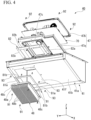
- FIG. 3 is an exploded perspective view that shows the electric components box 40.
- the electric components box 40 has an electric components box main body 41, and a lid 42.
- the electric components box main body 41 is a box shape member that has an opening 41h which opens to the top side.
- the opening 41h is rectangular shape which has a pair of sides that extend in the front-rear direction X, and a pair of sides that extend in the left-right direction Y.
- the opening 41h extends in the left-right direction Y.
- a bottom wall portion 41a of the electric components box main body 41 has an inclined wall portion 41b that inclines in the front-rear X direction with respect to a plane (XY plane) that is orthogonal to the vertical direction Z.
- the inclined wall portion 41b is located on the top side, as the rear side (-X side) is approached.
- the inclined wall portion 41b configures a rear side portion of the bottom wall portion 41a.
- An end of the rear side of the inclined wall portion 41b is an end on the rear side of the bottom wall portion 41a.
- the bottom wall portion 41a is a wall portion that is located on the bottom side.
- FIG. 4 is an exploded perspective view that shows the electric components box main body 41 and various parts affixed to the electric components box main body 41. As shown in FIG. 4 , a rectangular shaped through hole 41f is formed on the inclined wall portion 41b. The through hole 41f is formed on a portion on the right side (+Y side) out of the inclined wall portion 41b.
- the first electric parts 70 are housed on an inside of the electric components box 40.
- the first electric parts 70 has a substrate 71, and a plurality of electric parts 72 that are attached to the substrate 71.
- the substrate 71 is a long rectangular shape that faces the top side and the front side (+X side).
- the substrate 71 is a control board having a control circuit that controls the outdoor unit 10 mounted thereon.
- the plurality of electric parts 72 are attached to a surface on the top side of the substrate 71.
- the plurality of electric parts 72 include a micro-computer that conducts control of various parts of the outdoor unit 10, and a switching part or the like that switches a connection state of a portion of the control circuit that is mounted on the substrate 71.
- the substrate 71 is fixed to the inclined wall portion 41b via a substrate holding member 47.
- the substrate holding member 47 has a resin case 47a that supports the substrate 71 from the bottom side, and a frame shaped resin holder 47b that sandwiches an outside edge of the substrate 71 between the resin case 47a and the resin holder 47b.
- the resin holder 47b is fixed to the resin case 47a using a plurality of bolts 92.
- the resin case 47a is fixed to the inclined wall portion 41b using a plurality of bolts 93.
- the plurality of bolts 93 are fastened to the resin case 47a, after being inserted from an outside of the electric components box 40, through bolt holes that are formed on a circumferential edge of the through hole 41f out of the inclined wall portion 41b.
- a rectangular frame shaped sealing member 82 is provided between the resin case 47a and the inclined wall portion 41b.
- the frame shaped sealing member 82 seals a space between the resin case 47a and the inclined wall portion 41b.
- the frame shaped sealing member 82 is configured by combining a pair of first sealing materials 82a that extend in a direction of inclination of the inclined wall portion 41b, and a pair of second sealing materials 82b that extend in the left-right direction Y, into a rectangular frame shape. Holes through which bolts 93 used to fix the resin case 47a to the inclined wall portion 41b are inserted, are formed on the pair of first sealing materials 82a and the pair of second sealing materials 82b.
- the frame shaped sealing member 82 is elastically deformable. Materials that configure the frame shaped sealing member 82 for example, include urethane, and EPDM (Ethylene Propylene Diene Methylene) material (ethylene propylene diene rubber) or the like.
- a heatsink 48 is attached to a surface on the bottom side of the resin case 47, using a plurality of bolts 91.
- the heatsink 48 protrudes to the outside of the electric components box 40 via the through hole 41f formed on the inclined wall portion 41b.
- the heatsink 48 has a base 48a, a plurality of fins 48b that protrude from the base 48a to the bottom side and to the rear side (-X side), and a pair of flanges 48c that protrude from the base 48a to both sides in the left-right direction Y.
- the base 48a is in contact with parts that generate heat, out of the electric parts 72 attached to the substrate 71, via a through hole 47c formed on the resin case 47a.
- the base 48a plugs the through hole 41f formed on the inclined wall portion 41b, from the inside of the electric components box main body 41.
- the pair of flanges 48c are fixed to the resin case 47 by the plurality of bolts 91.
- Plate surfaces of the plurality of fins 48b are rectangular shapes that face the left-right direction Y.
- the plurality of fins 48b are disposed so as to align with intervals therebetween in the left-right direction Y.
- the plurality of fins 48b protrude to the outside of the electric components box 40, from the through hole 41f formed on the inclined wall portion 41b, to the bottom side and to the rear side (-X side).
- the plurality of fins 48b protrude to a direction that inclines towards the front-rear direction X with respect to the vertical direction Z.
- a frame shaped sealing member 81 is provided between the resin case 47a and the heatsink 48.
- the frame shaped sealing member 81 seals a space between the resin case 47a and the heatsink 48.
- the frame shaped sealing member 81 is configured by combining a pair of first sealing materials 81a that extend in a direction of inclination of the inclined wall portion 41b, and a pair of second sealing materials 81b that extend in the left-right direction Y, into a rectangular frame shape.
- the frame shaped sealing member 81 is elastically deformable.
- Materials that configure the frame shaped sealing member 81 for example, include urethane, and EPDM (Ethylene Propylene Diene Methylene) material (ethylene propylene diene rubber) or the like.
- the through hole 41f formed on the inclined wall portion 41b is sealed by the frame shaped sealing member 81 and the frame shaped sealing member 82. Accordingly, it is possible to prevent the refrigerant 19 from leaking to the inside of the electric components box 40, from the through hole 41f. There are few times when the first electric parts 70, the substrate holding member 47, and the heatsink 48 are removed after being attached to the electric components box main body 41. As such, the frame shaped sealing member 81 and the frame shaped sealing member 82 do not degrade easily, and sealing ability of the through hole 41f is not easily lost.
- FIG. 5 is a perspective view that shows the electric components box main body 41 and the first electric parts 70.
- elastically deformable portions 43, 44, 45, and 46 are formed on an edge of the opening 41h of the electric components box main body 41.
- the elastically deformable portions 43, 44, 45, and 46 are portions that are elastically deform in the vertical direction Z.
- the elastically deformable portions 43, 44, 45, and 46 are formed by conducting press work on sheet metal.
- the elastically deformable portions 43, 44, 45, and 46 are integrally formed with the electric components box main body 41.
- the elastically deformable portion 43 is formed on an edge located on the rear side (-X side), out of edges of the rectangular shaped opening 41h.
- the elastically deformable portion 44 is formed on an edge located on the front side (+X side), out of edges of the rectangular shaped opening 41h.
- the elastically deformable portion 45 is formed on an edge located on the left side (-Y side), out of edges of the rectangular shaped opening 41h.
- the elastically deformable portion 46 is formed on an edge located on the right side (+Y side), out of edges of the rectangular shaped opening 41h.
- the elastically deformable portion 43 and the elastically deformable portion 44 extend in the left-right direction Y.
- the elastically deformable portion 45 and the elastically deformable portion 46 extend in the front-rear direction X.
- Each of the elastically deformable portions 43, 44, 45, and 46 is almost formed on entire length of each edge of the rectangular shaped opening 41h. Details pertaining to the elastically deformable portions 43, 44, 45, and 46 are mentioned in later paragraphs.
- Flanges 41c, 41d, and 41e are provided on the electric components box main body 41.
- the flange 41c protrudes to the rear side (-X side), from a top end of a surface on the rear side of the electric components box main body 41.
- the flange 41d protrudes to the front side (+X side), from a top end of a surface on the front side of the electric components box main body 41.
- the flange 41e protrudes to the left side (-Y side), from an end on the left side of the elastically deformable portion 45.
- the flange 41c and the flange 41d are long thin rectangular shaped plates that extend in the left-right direction Y.
- the flange 41e is a long thin rectangular shaped plate that extends in the front-rear direction X. Plate surfaces of the flanges 41c, 41d, and 41e face the vertical direction Z.
- the flanges 41c and the 41d are formed by portions of separate members that are fixed to the electric components box main body 41. Said separate members that form the flanges 41c and 41d are L shaped metallic plates, as seen from the left-right direction Y.
- the flange 41e is integrally formed with the elastically deformable portion 45.
- FIG. 6 is a cross-sectional view that shows a portion of the electric components box 40, as seen from cross-sectional VI-VI of FIG. 2 .
- the lid 42 is located on the top side of the electric components box main body 41.
- the lid 42 is fixed to the electric components box main body 41.
- the lid 42 plugs the opening 41h of the electric components box main body 41.
- the lid 42 has a ceiling plate 42a, a frame 42b, and flanges 42c, 42d and 42e.
- the ceiling plate 42a is a long rectangular plate that extends in the left-right direction Y.
- a plate surface of the ceiling plate 42a faces the vertical direction Z.
- the frame 42b protrudes to the bottom side from an outer circumferential edge of the ceiling plate 42a.
- the frame 42b is a rectangular shaped frame that has a pair of edges that extend in the front-rear direction X, and a pair of edges that extend in the left-right direction Y. Top ends of the electric components box main body 41 are fitted into inner surfaces of the frame 42b.
- the flange 42c protrudes to the rear side from a bottom end of a portion located on the rear side (-X side) out of the frame 42b.
- the flange 42d protrudes to the front side from a bottom end of a portion located on the front side (+X side) out of the frame 42b.
- the flange 42e protrudes to the left side from a bottom end of a portion located on the left side (-Y side) out of the frame 42b.
- the flange 42c and the flange 42d are long thin rectangular shapes that extend in the left-right direction Y.
- the flange 42e is a long thin rectangular shape that extends in the front-rear direction X. Plate surfaces of the flanges 42c, 42d, and 42e face the vertical direction Z.
- the flange 42c is disposed so as to overlay the flange 41c provided in the electric components box main body 41 from the top side.
- the flange 42d is disposed so as to overlay the flange 41d provided in the electric components box main body 41 from the top side.
- the flange 42e is disposed so as to overlay the flange 41e provided in the electric components box main body 41 from the top side.
- the flange 42c is fixed to the flange 41c by three fastening members 90.
- the flange 42d is fixed to the flange 41d by three fastening members 90.
- the flange 42e is fixed to the flange 41e by two fastening members 90.
- the lid 42 is fixed to the electric components box main body 41 by a plurality of the fastening members 90 that fix each of the flanges 42c, 42d, and 42e.
- the fastening members 90 are self-tapping screws.
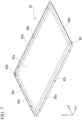
- FIG. 7 is a perspective view that shows a lid 42 in the first embodiment.
- a bottom surface of the ceiling plate 42a of the lid 42 is fixed to a frame shaped sealing member 80.
- the frame shaped sealing member 80 is a long rectangular shape in the left-right direction Y.
- the frame shaped sealing member 80 is fixed over an entire circumference of a circumferential edge on the bottom surface of the ceiling plate 42a.
- the frame shaped sealing member 80 is for example joined to the bottom surface of the ceiling plate 42a using an adhesive.
- the frame shaped sealing member 80 is fitted to an inside of the ceiling plate 42a of the lid 42.
- the frame shaped sealing member 80 seals spaces between the elastically deformable portions 43, 44, 45, 46 and the lid 42.
- the frame shaped sealing member 80 is configured by combining a pair of sealing materials 80a and 80b that extend in the left-right direction Y, and a pair of sealing materials 80c and 80d that extend in the front-rear direction X, into a rectangular frame shape.
- the sealing material 80a configures a portion located on the rear side (-X side), out of the frame shaped sealing member 80.
- the sealing material 80b configures a portion located on the front side (+X side), out of the frame shaped sealing member 80.
- the sealing material 80c configures a portion located on the left side (-Y side), out of the frame shaped sealing member 80.
- the sealing material 80d configures a portion located on the right side (+Y side), out of the frame shaped sealing member 80.
- the frame shaped sealing member 80 is elastically deformable.
- Materials that configure each of the sealing materials 80a, 80b, 80c, and 80d of the frame shaped sealing member 80 for example, include urethane, and EPDM (Ethylene Propylene Diene Methylene) material (ethylene propylene diene rubber) or the like.
- the elastically deformable portions 43, 44, 45, and 46 are explained in more detail.
- the explanation of the elastically deformable portion 43, out of the elastically deformable portions 43, 44, 45, and 46 is representative of portions thereof, and for cases where configurations of the elastically deformable portions 44, 45, and 46 have similar configurations as the elastically deformable portion 43, explanations thereof are omitted.
- FIG. 8 is a perspective view that shows a portion of the electric components box main body 41, and is a partial enlarged view of FIG. 5 .
- FIG. 9 is a partial cross-sectional view that shows a portion of the electric components box 40.
- FIG. 5 , FIG. 8 and FIG. 9 a state where the lid 42 is not fixed to the electric components box main body 41, and where the elastically deformable portion 43 is not deformed, is shown.
- FIG. 6 a state where the lid 42 is fixed to the electric components box main body 41, and where the elastically deformable portion 43 is deformed.
- the lid 42 is fixed to the electric components box main body 41, in other words, the elastically deformable portion 43 is in a state of being deformed.
- the elastically deformable portion 43 protrudes to a direction that faces an inside of the opening 41h from an edge of the opening 41h, as seen from the top side.
- the elastically deformable portion 43 protrudes to the front side (+X side) from the edge of the opening 41h.
- the elastically deformable portion 43 in a state where the lid 42 is not fixed to the electric components box main body 41 and no elastic deformation takes place, the elastically deformable portion 43 extends in a direction that inclines to the vertical direction Z with respect to the front-rear direction X, from the edge of the opening 41h.
- the nondeformed elastically deformable portion 43 protrudes to a direction located on the top side, as the front side thereof is approached, from the edge of the opening 41h.
- the elastically deformable portion 43 moves away to the vertical direction Z from the opening 41h, as the elastically deformable portion 43 separates to the front side in the front-rear direction X from the edge of the opening 41h.
- an amount of inclination ⁇ in a direction of protrusion thereof, where the elastically deformable portion 43 inclines with respect to the front-rear direction X is for example greater than or equal to 5 degrees, and less than or equal to 30.
- the elastically deformable portion 43 protrudes along a bottom surface of the sealing material 80a in the front-rear direction X, from the edge of the opening 41h, in a state where the lid 42 is fixed to the electric components box main body 41.
- the elastically deformable portion 43 in a state of being elastically deformed to the bottom side, indirectly contacts the lid 42.
- the expression a "certain object contacts another object indirectly" implies that that said certain object is indirectly in contact with said another object, by having an object different from both said objects sandwiched therebetween.
- the elastically deformable portion 43 is disposed so as to sandwich the sealing material 80a of the sealing member 80 in the vertical direction Z, with the ceiling plate 42a of the lid 42.
- the sealing material 80a is in contact with the ceiling plate 42a and the elastically deformable portion 43. Accordingly, the elastically deformable portion 43 is indirectly in contact with the lid 42, via the sealing material 80a.
- the elastically deformable portion 43 is in contact with the bottom surface of the sealing material 80a.
- the elastically deformable portion 43 applies a force F to the sealing material 80a in the top side direction. Accordingly, the elastically deformable portion 43 holds the sealing material 80a down onto the lid 42. More specifically, the elastically deformable portion 43 holds the sealing material 80a down onto the bottom surface of the ceiling plate 42a.
- the elastically deformable portion 43 applies a force F to the lid 42, by applying the force F to the sealing material 80a in the top side direction.
- the elastically deformable portion 43 has a leaf spring 43a, and a bend 43b.
- the leaf spring 43a protrudes to the front-rear direction X from the edge of the opening 41h.
- the leaf spring 43a is a rectangular shaped plate that extends in the left-right direction Y.
- a plate surface on the top side of the leaf spring 43a contacts the bottom surface of the sealing material 80a. Accordingly, the leaf spring 43a indirectly contacts the lid 42, via the sealing material 80a.
- the leaf spring 43a With the edge of the opening 41h as a pivot point, the leaf spring 43a is elastically deformable in the vertical direction Z.
- the leaf spring 43a applies a force to the lid 42 in the top side direction, via the sealing material 80a.
- a plate surface on the top side of the leaf spring 43a is a flat surface 43d.
- the flat surface 43d indirectly contacts the lid 42, via the sealing material 80a.
- the flat surface 43d in a state where the lid 42 is fixed to the electric components box main body 41, the flat surface 43d is flat surface that is orthogonal with the vertical direction Z.
- the flat surface 43d applies a force to the lid 42 in the top side direction, via the sealing material 80a.
- the flat surface 43d becomes an inclined surface, having an inclination of ⁇ with respect to a plane (XYZ plane) that is orthogonal to the vertical direction Z.
- the bend 43b is connected to a tip of the leaf spring 43a, in the front-rear direction X.
- the bend 43b is connected to an end on the front side (+X side) of the leaf spring 43a.
- the bend 43b is bent to the bottom side, with respect to the leaf spring 43a.
- the phrase "the bend 43b is bent to the bottom side, with respect to the leaf spring 43a" is satisfied so long as the leaf spring 43a is bent such that the bend 43b is located to the bottom side, more than the leaf spring 43a.
- the bend 43b is folded back to the rear side (-X side), after being bent from the tip of the leaf spring 43a.
- the bend 43b is located on the bottom side of the leaf spring 43a.
- a gap is provided between the bend 43b and the leaf spring 43a in the vertical direction Z.
- the bend 43b is separately disposed to the bottom side, from the ceiling plate 42a of the lid 42, more than the leaf spring 43a.
- connection portion 43c of the leaf spring 43a and the bend 43b is rounded.
- the connection portion 43c is an arc shape that protrudes to the front side (+X side), as seen from the left-right direction Y.
- the connection portion 43c is a tip of the elastically deformable portion 43 in the front-rear direction X.
- the connection portion 43c is an end on the front side of the elastically deformable portion 43.
- the connection portion 43c is disposed in a location that overlaps with the sealing material 80a, as seen from the vertical direction Z.
- the connection portion 43c is separately located on the front-rear direction X, from both ends of the sealing material 80a in the front-rear direction X that are in contact with the elastically deformable portion 43.
- connection portion 43c is separately disposed to the rear side (-X side) more than inner edges of the frame shaped sealing member 80.
- the connection portion 43c is located between the inner edges of the frame shaped sealing member 80 and outer edges of the frame shaped sealing member 80, as seen from the vertical direction Z.
- a distance L in the vertical direction Z, between a top end of the elastically deformable portion 43 when not elastically deformed, and the edge of the opening 41h, is larger than a thickness T of the sealing material 80a in the vertical direction Z. Accordingly, even in a case where the frame shaped sealing member 80 is not provided, by fixing the lid 42 to the electric components box main body 41, the ceiling plate 42a contacts the elastically deformable portion 43, and it is possible to have the elastically deformable portion 43 elastically deform to the bottom side.
- the elastically deformable portion 44 is the same as the elastically deformable portion 43.
- the elastically deformable portion 44 holds the sealing material 80b down onto the lid 42.
- the elastically deformable portion 45 and the elastically deformable portion 46 protrude to a direction that faces the outside of the opening 41h, from the edge of the opening 41h, as seen from the top.
- the elastically deformable portion 45 protrudes to the left side (-Y side) from the edge of the opening 41h.
- the elastically deformable portion 46 protrudes to the right side (+Y side) from the edge of the opening 41h.
- the elastically deformable portion 45 and the elastically deformable portion 46 are provided so as to be symmetrical about the left-right direction Y.
- the elastically deformable portion 45 holds the sealing material 80c down onto the lid 42.
- the elastically deformable portion 46 holds the sealing material 80d down onto the lid 42.
- the front-rear direction X in which the elastically deformable portions 43 and 44 protrude from the edge of the opening 41h
- the left-right direction Y in which the elastically deformable portions 45 and 46 protrude from the edge of the opening 41h
- the link 31 protrudes to the right side, from a top end of the electric components box 40.
- the link 31 is a flat semi-rectangular shape in the vertical direction Z.
- a right end of the link 31 is separately disposed on the top side of the partition member 11c.
- the holding member 60 is disposed on the inside of the mechanical room 11b.
- the holding member 60 is fixed to the electric components box 40 via the link 31 and the wall portion 50.
- the holding member 60 is a member that holds the second electric parts 73 and 74.
- the holding member 60 has a first holding member 61 and a second holding member 62.
- the first holding member 61 and the second holding member 62 in the first embodiment are mutually separate members.
- the first holding member 61 and the second holding member 62 are sheet metal members.
- the first holding member 61 and the second holding member 62 are fixed to one another.
- the second electric parts 73 are held by the first holding member 61.
- the second electric parts 74 are held by the second holding member 62.
- the second electric parts 73 and 74 are electrically connected to the substrate 71 of the first electric parts 70, by wires not shown on the drawings.
- the second electric parts 73 is a sensor substrate having a sensor which is not shown on the drawings electrically connected thereto, disposed on the inside of the mechanical room 11b. In contrast to the substrate 71, no switching part is mounted onto the second electric parts 73, which is a sensor substrate.
- the second electric parts 74 is a terminal block having a plurality of wires connected thereto.
- the wall portion 50 is located on the top side of the partition member 11c.
- the wall portion 50 is located between the partition member 11c, and a ceiling surface panel of the housing 11 that is not shown on the drawings, in the vertical direction Z.
- the wall portion 50 plugs a gap between the partition member 11c and said ceiling surface panel.
- a hole to having wires that connect the first electric parts 70 housed within the electric components box 40, with parts disposed on the inside of the mechanical room 11b is formed on the wall portion 50.
- FIG. 9 an operator attaching the lid 42 to the electric components box main body 41, brings the lid 42 having the frame shaped sealing member 80 fixed thereto closer to the electric components box main body 41 from the top side.
- the operator continues to bring the lid 42 closer to the electric components box main body 41 until each of the flanges 42c, 42d, and 42e of the lid 42 contact each of the flanges 41c, 41d, and 41e of the electric components box main body 41, and fixes each of the flanges 42c, 42d and 42e to each of the flanges 41c, 41d, and 41e using the fastening members 90.
- each of the various sealing materials 80a, 80b, 80c, and 80d that configure the frame shaped sealing member 80 contact each of the elastically deformable portions 43, 44, 45, and 46.
- the various elastically deformable portions 43, 44, 45, and 46 are pushed onto the ceiling plate 42a of the lid 42, via the frame shaped sealing member 80, and elastically deform to the bottom side.
- each of the flanges 42c, 42d, and 42e be in contact with, and fixed to the various flanges 41c, 41d, and 41e, it is possible to attach the lid 42 to the electric components box main body 41, in a state where the various elastically deformable portions 43, 44, 45, 46 are elastically deformed in the bottom side.
- the elastically deformable portion 43 is formed on the edge of the opening 41h of the electric components box main body 41, in the vertical direction Z.
- the elastically deformable portion 43 indirectly contacts the lid 42 in a state of being elastically deformed to the bottom side, which is a side opposite to the top side in the vertical direction Z, and applies a force F to the lid 42 in the top side direction.
- it is possible to suppress gap formation between the electric components box main body 41 and the lid 42, and it is possible to suppress the a degradation in sealing ability of the electric components box 40.
- the refrigerant 19 that has leaked from the refrigerant pipe 18a on the inside of the mechanical room 11b, leaks to the inside of the blower room 11a it is possible to suppress the refrigerant 19 from leaking to the inside of the electric components box 40.
- the refrigerant 19 that has leaked to the inside of the mechanical room 11b is for example, in a gaseous state.
- the sealing material 80a is provided between the elastically deformable portion 43 and the lid 42, in the vertical direction Z, and the elastically deformable portion 43 holds the sealing material 80a down onto the lid 42.
- the elastically deformable portion 43 holds the sealing material 80a down onto the lid 42.
- the elastically deformable portion 43 protrudes to the front-rear direction X which intersects with the vertical direction Z, from an edge of the opening 41h.
- a tip of the elastically deformable portion 43 in the front-rear direction X in other words, the connection portion 43c, is disposed in a location so as to overlap with the sealing material 80a, as seen from the vertical direction Z.
- the connection portion 43c of the elastically deformable portion 43 from directly contacting the ceiling plate 42a of the lid 42, and it is possible to have the elastically deformable portion 43 suitably come into contact, or the like, with the sealing material 80a.
- the tip of the elastically deformable portion 43 in the front-rear direction X in other words, the connection portion 43c is rounded.
- the connection portion 43c of the elastically deformable portion 43 is located to the top side, compared to other portions of the elastically deformable portion 43.
- the connection portion 43c first comes into contact with the sealing material 80a.
- connection portion 43c is of a shape that has a sharp angle
- the connection portion 43c is rounded, when attaching the lid 42 to the electric components box main body 41, it is possible to suppress the connection portion 43c from getting caught onto the sealing material 80a.
- a tip of the elastically deformable portion 43 in the front-rear direction X is separately located in the front-rear direction X from both ends of the sealing material 80a. As such, even when discrepancies or the like in dimensions of the sealing material 80a are present, it is still possible to suitably have the elastically deformable portion 43 contact the sealing material 80a.
- the elastically deformable portion 43 protrudes to the front-rear direction X which intersects with the vertical direction Z, from an end of the opening 41h.
- the elastically deformable portion 43 is connected to the leaf spring 43a which applies a force F to the lid 42 in the top side direction, and is connected to a tip of the leaf spring 43a in the direction of protrusion (front-rear direction X) of the leaf spring 43a.
- the elastically deformable portion 43 has the bend 43b that is bent to the bottom side, with respect to the leaf spring 43a. As such, it is possible to easily have the tip of the elastically deformable portion 43, in other words, the connection portion 43c, be rounded in the front-rear direction X.
- the elastically deformable portion 43 has the flat surface 43d, which applies a force F to the lid 42 in the top side direction. As such, it is possible to easily make a surface area of the above part out of the elastically deformable portion 43 which applies the force F in the top direction onto the lid 42 larger, and it is possible to more easily suppress the degradation in sealing ability of the electric components box 40.
- the flat surface 43d is in contact with the sealing material 80a as in the first embodiment, it is possible to make a surface area of a portion out of the elastically deformable portion 43 that contacts the sealing material 80a larger, and it is possible to more suitably hold down the sealing material 80a using the elastically deformable portion 43. Accordingly, it is possible to more suitably suppress the degradation in sealing ability of the electric components box 40.
- the same effects as the effects of the elastically deformable portion 43 explained above are obtainable from the elastically deformable portions 44, 45, and 46.
- the elastically deformable portion 44 holds the sealing material 80b down onto the lid 42.
- the elastically deformable portion 45 holds the sealing material 80c down onto the lid 42.
- the elastically deformable portion 46 holds the sealing material 80d down onto the lid 42.
- the lid 42 is opened and closed with respect to the electric components box main body 41 relatively frequently, due to inspection or the like of the first electric parts 70.
- the sealing ability of the opening 41h of the electric components box main body 41 degrades more easily.
- the substrate holding member 47 and the heatsink 48 or the like are removed less frequently, even if a construction similar to the construction of the elastically deformable portions 43, 44, 45, and 46 is not provided, the risk of degradation in sealing ability of the through hole 41f formed on the inclined wall portion 41b is low.
- the construction of the elastically deformable portions 43, 44, 45, and 46 may also be adopted at a location of the through hole 41f.
- the electric components box 40 is disposed on the inside of the blower room 11a. Since leakage of the refrigerant 19 easily occurs on the inside of the mechanical room 11b, by disposing the electric components box 40 on the inside of the blower room 11a, it is possible to suppress the refrigerant 19 from leaking into the electric components box 40. As previously mentioned, the density of the refrigerant 19 in a gaseous state is larger than the density of air.
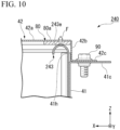
- FIG. 10 is a cross-sectional view that shows a portion of an electric components box 240 in a second embodiment.
- configurations similar to the configurations of the aforementioned embodiment have the same reference symbols or the like affixed thereto, with explanations thereof being omitted.
- the electric components box 240 of the second embodiment has an elastically deformable portion 243, and a curve 243e that extends in a curved shape so as to convex to the top side, from the edge of the opening 41h.
- the elastically deformable portion 243 in the second embodiment is formed from the curve 243e.
- the curve 243e is an arc shape that convexes to the top side, as seen from the left-right direction Y. More specifically, the curve 243e is approximately a semicircular shape that convexes to the top side, as seen from the left-right direction Y.
- the curve 243e is in contact with the bottom surface of the sealing material 80a.
- an end in the top side out of the curve 243e is in contact with the bottom surface of the sealing material 80a.
- the curve 243e holds the sealing material 80a down onto the ceiling plate 42a of the lid 42.
- the curve 243e applies a force F to the lid 42 in the top side direction, via the sealing material 80a.
- elastically deformable portions other than the elastically deformable portion 243 also have a curve portion.
- Other configurations of the electric components box 240 are the same as other configurations of the electric components box 40 in the first embodiment.
- the elastically deformable portion 243 applies a force F to the lid 42 in the top side direction, via the curve 243e.
- a portion that contacts the sealing member 80a out of the elastically deformable portion 243 is an apex of the curve 243e that extends in a curved shape so as to convex to the top side, from the edge of the opening 41h.
- a shape of an elastically deformable portion is not particularly limited. How the elastically deformable portion is made is not limited.
- the elastically deformable portion may be made of resin.
- the elastically deformable portion and an electric components box main body may be integrally formed. So long as a number of the elastically deformable portions is greater than or equal to one, the number thereof is not particularly limited.
- a portion of the four elastically deformable portions 43, 44, 45, and 46 need not be provided. Out of edges of an opening of an electric components box main body, the elastically deformable portion may only be formed on a location where there is a relatively higher chance of a refrigerant leaking.
- the sealing material may be a sealing material that is configured from any material.
- the frame shaped sealing member 80 may be formed by having the four sealing materials 80a, 80b, 80c and 80d integrally formed into a single sealing material.
- the sealing material need not be provided between the elastically deformable portion and the lid in the first direction (vertical direction Z). In such case, by having the elastically deformable portion, in a state of being elastically deformed, directly come into contact with the lid, the space between the lid and the electric components box main body is sealed.
- An electric components box may be disposed in any location on an inside of a housing of a heat exchange unit.
- the electric components box 40 may be disposed on the inside of the mechanical room 11b.
- the first direction to which the opening of the electric components box main body opens to is not particularly limited, and may be any direction other than the vertical direction.
- a second direction to which the elastically deformable portion protrudes, from an edge of the opening of the electric components box main body may be a direction which intersects the first direction, or may be a direction that is orthogonal to the first direction.
- a heat exchange unit in the present disclosure may be an indoor unit of a refrigeration cycle device.
- the refrigeration cycle device that includes the heat exchange unit may be a refrigeration cycle that circulates a refrigerant, and is not limited to an air conditioner.
- the refrigeration cycle device may be water heater of a heat pump or the like.
Landscapes
- Engineering & Computer Science (AREA)
- Mechanical Engineering (AREA)
- General Engineering & Computer Science (AREA)
- Chemical & Material Sciences (AREA)
- Combustion & Propulsion (AREA)
- Physics & Mathematics (AREA)
- Thermal Sciences (AREA)
- Casings For Electric Apparatus (AREA)
- Cooling Or The Like Of Electrical Apparatus (AREA)
- Devices That Are Associated With Refrigeration Equipment (AREA)
Abstract
Description
- The present disclosure relates to a heat exchange unit, and a refrigeration cycle device.
- As shown in Patent Document 1 for example, an air conditioning device that includes an electronic unit, the electronic unit having a sealing material that seals a space between a case main body (electric components box main body) and a case cover (cover main body) provided is known.
- [Patent Document 1]
Japanese Unexamined Application No. 10-220824 - In the above electronic unit, when a sealing material wears due to aging, or when gaps form due to opening and closing a case lid with respect to a case main body multiple times or the like, there is a risk of the electronic unit (electric components box) exhibiting a degradation in sealing ability thereof.
- The present disclosure has been made in order to address the problem above, and an object is to provide a heat exchange unit having a construction where a degradation in sealing ability is suppressed, and a refrigeration cycle device that includes such heat exchange unit.
- An embodiment of a heat exchange unit which is a heat exchange unit of a refrigeration cycle device according to the present disclosure includes: a housing; a heat exchanger housed on an inside of the housing; a blower housed on the inside of the housing, and an electric components box housed on the inside of the housing, wherein the electric components box has an electric components box main body having an opening that opens to a first side in a first direction, and a lid that plugs the opening, and is fixed to the electric components box main body, an elastically deformable portion that is elastically deformable in the first direction, is formed on an edge of the opening, the elastically deformable portion directly or indirectly contacts the lid, in a state where the elastically deformable portion is elastically deformed to a second side that is opposite to the first side in the first direction, and a force is applied to the lid in the first side direction.
- A refrigeration cycle device according to an embodiment of the present disclosure includes an outdoor unit, and an indoor unit, wherein the outdoor unit or the indoor unit is the heat exchange unit mentioned above.
- According to the present disclosure, it is possible to provide a heat exchange unit of a refrigeration cycle device where a degradation in sealing ability of an electric components box thereof is suppressed.
-
- [
FIG. 1 ] A schematic view that shows an outline configuration of a refrigeration cycle device in a first embodiment. - [
FIG. 2 ] A perspective view that shows a portion of an outdoor unit in the first embodiment. - [
FIG. 3 ] An exploded perspective view that shows an electric components box in the first embodiment. - [
FIG. 4 ] An exploded perspective view that shows an electric components box main body and various parts affixed to the electric components box main body in the first embodiment. - [
FIG. 5 ] A perspective view that shows the electric components box main body and first electric parts in the first embodiment. - [
FIG. 6 ] A cross-sectional view that shows a portion of the electric components box in the first embodiment, as seen from cross-sectional VI-VI ofFIG. 2 . - [
FIG. 7 ] A perspective view that shows a lid in the first embodiment. - [
FIG. 8 ] A perspective view that shows a portion of the electric components box main body in the first embodiment. - [
FIG. 9 ] A partial cross-sectional view that shows a portion of the electric components box in the first embodiment. - [
FIG. 10 ] A cross-sectional view that shows a portion of the electric components box in a second embodiment. - Hereinafter, an embodiment of the present disclosure is explained with reference to the drawings. The scope of the present disclosure is not limited to the embodiment below, and may be changed so long as the embodiment do not depart from the technical scope of the present disclosure. In the drawings below, to facilitate better understanding of the various embodiments, scales and dimensions or the like of various constructions may differ from scales and dimensions or the like of constructions in the drawings below.
- The drawings show an X axis, a Y axis, and a Z axis where appropriate. The X axis shows a side out of sides of a horizontal direction. The Y axis shows another side out of sides of the horizontal direction. The Z axis shows a vertical direction. In the explanation below, a horizontal direction along the X axis is referred to as a "front-rear direction X", and a horizontal direction along the Y axis is referred to as a "left-right direction Y". A vertical direction is referred to as a "vertical direction Z". The front-rear direction X, the left-right direction Y, and the vertical direction Z are mutually orthogonal directions. In the explanation below, a side out of sides of the vertical direction Z in which an arrow of the Z axis faces is a top side (+Z side). The other side out of sides of the vertical direction Z which faces an opposite side the arrow of the Z axis faces is a bottom side (-Z side). A side out of sides of the front-rear direction X in which an arrow of the X axis faces is a front side (+X side). A side out of sides of the front-rear direction X which faces an opposite side the arrow of the X axis faces is a rear side (-X side). The left-right direction Y in the embodiment below, is the left-right direction Y in a case where an
outdoor unit 10 is viewed from the front side (+X side). In other words, a side out of sides of the left-right direction Y in which an arrow of the Y axis faces is a right side (+Y side). A side out of sides in the left-right direction Y which faces an opposite side the arrow of the Y axis faces is a left side (-Y side). - In embodiments below, the vertical direction Z corresponds to a "first direction". The top side corresponds to a "first side" in the first direction. The bottom side corresponds to a "second side", a side that is opposite to the first side in the first direction.
-
FIG. 1 is a schematic view that shows an outline configuration of arefrigeration cycle device 100 in a first embodiment. Therefrigeration cycle device 100 is a device that uses a refrigeration cycle in which arefrigerant 19 is circulated. Therefrigeration cycle device 100 in the embodiment is an air conditioner. As shown inFIG. 1 , therefrigeration cycle device 100 includes theoutdoor unit 10, anindoor unit 20, and acirculation path 18. Theoutdoor unit 10 is disposed outdoors. Theindoor unit 20 is disposed indoors. Theoutdoor unit 10 and theindoor unit 20 are connected by thecirculation path 18 that circulates arefrigerant 19. Theoutdoor unit 10 and theindoor unit 20 are heat exchange units that conduct heat exchange with air. - By having the
refrigerant 19 that flows within thecirculation pathway 18, and theindoor unit 20 conduct heat exchange with air indoors, it is possible for theair conditioner 100 to adjust a temperature of the air indoors. A refrigerant such as a fluorine based refrigerant with a low global warming potential (GWP: Global Warming Potential), or a hydrocarbon based refrigerant or the like may be mentioned as examples of therefrigerant 19. A density of therefrigerant 19 in a gaseous state is larger than a density of air. Here, the fluorine based refrigerant with a low global warming potential is for example, HFC32. An example of the hydrocarbon based refrigerant is R290 (propane). Both the fluorine based refrigerant and the hydrocarbon based refrigerant are flammable refrigerants. - The
outdoor unit 10 includes ahousing 11, acompressor 12, aheat exchanger 13, aflow adjustment valve 14, ablower 15, a four-way valve 16, arefrigerant pipe 18a, and acontrol unit 30. Thecompressor 12, theheat exchanger 13, theflow adjustment valve 14, theblower 15, the four-way valve 16, therefrigerant pipe 18a and thecontrol unit 30 are housed on an inside of thehousing 11. - Out of the
circulation pathway 18, thecompressor 12, theheat exchanger 13, theflow adjustment valve 14, and the four-way valve 16 are provided on a portion located on the inside portion of thehousing 11. Out of thecirculation pathway 18, thecompressor 12, theheat exchanger 13, theflow adjustment valve 14, and the four-way valve 16 are connected by a portion located on the inside portion of thehousing 11. - Out of the
circulation pathway 18, the four-way valve 16 is provided on a part that is connected to a discharge side of thecompressor 12. By exchanging a portion of thecirculation pathway 18, it is possible for the four-way valve 16 to reverse a direction of flow of the refrigerant 19 within thecirculation pathway 18. When the path connected by the four-way valve 16 is the path of the four-way valve 16 that is shown by solid lines inFIG. 1 , the refrigerant 19 within thecirculation pathway 18 flows in the direction shown by the solid line arrow inFIG. 1 . On the other hand, when the path connected by the four-way valve 16 is the path of the four-way valve 16 that is shown by dashed lines inFIG. 1 , the refrigerant 19 flows within thecirculation pathway 18 in the direction shown by the dashed line arrow inFIG. 1 . - The
refrigerant pipe 18a is a pipe that configures a portion of thecirculation pathway 18. Therefrigerant pipe 18a is connected to a pipe that extends from theindoor unit 20. A plurality ofrefrigerant pipes 18a are provided on an inside of thehousing 11 of theoutdoor unit 10. - The
indoor unit 20 includes ahousing 21, aheat exchanger 22, ablower 23, and acontroller 24. Thehousing 21 houses theheat exchanger 22, theblower 23, and thecontroller 24 on an inside thereof. It is possible for theindoor unit 20 to have a cooling operation where the air of the room theindoor unit 20 is disposed in is cooled, and to have a heating operation where the air of the room theindoor unit 20 is disposed in is heated. - When the
indoor unit 20 is operated in the cooling operation, the refrigerant 19 that flows within thecirculation pathway 18 flows in the direction shown by solid lines inFIG. 1 . In other words, when theindoor unit 20 is operated in the cooling operation, the refrigerant 19 that flows within thecirculation pathway 18 circulates so as to return to thecompressor 12 after passing through thecompressor 12, theheat exchanger 13 of theoutdoor unit 10, theflow adjustment valve 14, and theheat exchanger 22 of theindoor unit 20 in such an order. During the cooling operation, theheat exchanger 13 of theoutdoor unit 10 functions as a condenser, and theheat exchanger 22 of theindoor unit 20 functions as an evaporator. - On the other hand, when the
indoor unit 20 is operated in the heating operation, the refrigerant 19 that flows within thecirculation pathway 18 flows in the direction shown by dashed lines inFIG. 1 . In other words, when theindoor unit 20 is operated in the heating operation, the refrigerant 19 that flows within thecirculation pathway 18 circulates so as to return to thecompressor 12 after passing through thecompressor 12, theheat exchanger 22 of theindoor unit 20, theflow adjustment valve 14, and theheat exchanger 13 on an inside of theoutdoor unit 10 in such an order. During the heating operation, theheat exchanger 13 of theoutdoor unit 10 functions as the evaporator, and theheat exchanger 22 on an inside of theindoor unit 20 functions as the condenser. - Next, the
outdoor unit 10 is explained in further detail.FIG. 2 is a perspective view that shows a portion of theoutdoor unit 10. As shown inFIG. 2 , thehousing 11 has ablower room 11a and amechanical room 11b that are partitioned from one another by apartition member 11c. Thepartition member 11c extends in the vertical direction Z. A plate surface of thepartition member 11c is a semi-rectangular plate that faces the left-right direction Y. A top end of thepartition member 11c is separately disposed to the bottom side, from a ceiling surface panel of thehousing 11 that is not shown on the drawings. The ceiling surface panel not shown on the drawings is a wall portion located on the top side out of wall portions that configure thehousing 11. - The
blower room 11a and themechanical room 11b are adjacently disposed in the left-right direction Y. A dimension of theblower room 11a in the left-right direction Y is larger than a dimension of themechanical room 11b in the left-right direction Y. Theblower room 11a is located on the left side of themechanical room 11b. Aheat exchanger 13 and theblower 15 are disposed on an inside of theblower room 11a. Theheat exchanger 13 in the present embodiment, as seen from the vertical direction Z, is approximately L shaped. Theheat exchanger 13 has afirst portion 13a that extends in the left-right direction Y as seen from the vertical direction Z, and asecond portion 13b that extends to the front side (+X side) from an end on the left side of thefirst portion 13a. Thefirst portion 13a is disposed on a rear end of the inside of theblower room 11a. A left end of thefirst portion 13a is exposed to an inside of themechanical room 11b. Thec refrigerant pipe 18a which is disposed on the inside of themechanical room 11b is connected to a right end of thefirst portion 13a. Accordingly, therefrigerant pipe 18a is connected to theheat exchanger 13. Thesecond portion 13b is disposed on a left end of an inside of theblower room 11a. The blower 15is located on a front side of thefirst portion 13a in theheat exchanger 13, and a right side of thesecond portion 13b in theheat exchanger 13, on the inside of theblower room 11a. - When the
blower 15 is driven, the air is taken into theblower room 11a from an intake port not shown on the drawings, that is provided on a wall portion on the rear side (-X side) of theblower room 11a. The air that is taken into theblower room 11a passes through theheat exchanger 13, and is discharged to an outside of thehousing 11 from an exhaust port not shown on the drawings, that is provided on a wall portion on the front side (+X side) of theblower room 11a. As such, theblower 15 sends the air to theheat exchanger 13. - The
compressor 12 is disposed on the inside of themechanical room 11b. Thecompressor 12 is disposed on a bottom side portion out of the inside of themechanical room 11b. Thecompressor 12 is a semi-cylindrical shape that extends in the vertical direction Z. As shown inFIG. 1 , the plurality ofrefrigerant pipes 18a are disposed on the inside of themechanical room 11b. - The
control unit 30 controls various parts of theoutdoor unit 10. Thecontrol unit 30, for example, is a system controller that regulates control of an entirety of therefrigeration cycle device 100. As shown inFIG. 2 , thecontrol unit 30 is disposed so as to straddle between the inside of theblower room 11a and the inside of themechanical room 11b. Thecontrol unit 30 extends in the left-right direction Y. Thecontrol unit 30 has theelectric components box 40, firstelectric parts 70, alink 31, awall portion 50, a holdingmember 60, and secondelectric parts - The
electric components box 40 is a long box shape that extends in the left-right direction Y. Theelectric components box 40 is housed on the inside of thehousing 11. In the first embodiment, theelectric components box 40 is disposed on the inside of theblower room 11a. Theelectric components box 40 is separately located on the top side of theblower 15, on the inside of theblower room 11a. Theelectric components box 40 is located on a top end, on the inside of theblower room 11a. Theelectric components box 40 is fixed to thehousing 11. An end on the right side of theelectric components box 40 is separately located more to the left side than thepartition member 11c. In the first embodiment, theelectric components box 40 is made of a metal. Theelectric components box 40 is for example made by conducting press work on sheet metal. -
FIG. 3 is an exploded perspective view that shows theelectric components box 40. As shown inFIG. 3 , theelectric components box 40 has an electric components boxmain body 41, and alid 42. The electric components boxmain body 41 is a box shape member that has anopening 41h which opens to the top side. Theopening 41h is rectangular shape which has a pair of sides that extend in the front-rear direction X, and a pair of sides that extend in the left-right direction Y. Theopening 41h extends in the left-right direction Y. - A
bottom wall portion 41a of the electric components boxmain body 41 has aninclined wall portion 41b that inclines in the front-rear X direction with respect to a plane (XY plane) that is orthogonal to the vertical direction Z. Theinclined wall portion 41b is located on the top side, as the rear side (-X side) is approached. Theinclined wall portion 41b configures a rear side portion of thebottom wall portion 41a. An end of the rear side of theinclined wall portion 41b is an end on the rear side of thebottom wall portion 41a. Out of wall portions that configure the electric components boxmain body 41, thebottom wall portion 41a is a wall portion that is located on the bottom side. -
FIG. 4 is an exploded perspective view that shows the electric components boxmain body 41 and various parts affixed to the electric components boxmain body 41. As shown inFIG. 4 , a rectangular shaped throughhole 41f is formed on theinclined wall portion 41b. The throughhole 41f is formed on a portion on the right side (+Y side) out of theinclined wall portion 41b. - As shown in
FIG. 3 , out of theinclined wall portion 41b, an inner surface that faces an inside of the electric components boxmain body 41 is fixed to the firstelectric parts 70. The firstelectric parts 70 are housed on an inside of theelectric components box 40. The firstelectric parts 70 has asubstrate 71, and a plurality ofelectric parts 72 that are attached to thesubstrate 71. Thesubstrate 71 is a long rectangular shape that faces the top side and the front side (+X side). Thesubstrate 71 is a control board having a control circuit that controls theoutdoor unit 10 mounted thereon. The plurality ofelectric parts 72 are attached to a surface on the top side of thesubstrate 71. The plurality ofelectric parts 72 include a micro-computer that conducts control of various parts of theoutdoor unit 10, and a switching part or the like that switches a connection state of a portion of the control circuit that is mounted on thesubstrate 71. - In the first embodiment, the
substrate 71 is fixed to theinclined wall portion 41b via asubstrate holding member 47. As shown inFIG. 4 , thesubstrate holding member 47 has aresin case 47a that supports thesubstrate 71 from the bottom side, and a frame shapedresin holder 47b that sandwiches an outside edge of thesubstrate 71 between theresin case 47a and theresin holder 47b. Theresin holder 47b is fixed to theresin case 47a using a plurality ofbolts 92. Theresin case 47a is fixed to theinclined wall portion 41b using a plurality ofbolts 93. The plurality ofbolts 93 are fastened to theresin case 47a, after being inserted from an outside of theelectric components box 40, through bolt holes that are formed on a circumferential edge of the throughhole 41f out of theinclined wall portion 41b. - A rectangular frame shaped sealing
member 82 is provided between theresin case 47a and theinclined wall portion 41b. The frame shaped sealingmember 82 seals a space between theresin case 47a and theinclined wall portion 41b. The frame shaped sealingmember 82 is configured by combining a pair offirst sealing materials 82a that extend in a direction of inclination of theinclined wall portion 41b, and a pair ofsecond sealing materials 82b that extend in the left-right direction Y, into a rectangular frame shape. Holes through whichbolts 93 used to fix theresin case 47a to theinclined wall portion 41b are inserted, are formed on the pair offirst sealing materials 82a and the pair ofsecond sealing materials 82b. The frame shaped sealingmember 82 is elastically deformable. Materials that configure the frame shaped sealingmember 82 for example, include urethane, and EPDM (Ethylene Propylene Diene Methylene) material (ethylene propylene diene rubber) or the like. - A
heatsink 48 is attached to a surface on the bottom side of theresin case 47, using a plurality ofbolts 91. Theheatsink 48 protrudes to the outside of theelectric components box 40 via the throughhole 41f formed on theinclined wall portion 41b. Theheatsink 48 has abase 48a, a plurality offins 48b that protrude from thebase 48a to the bottom side and to the rear side (-X side), and a pair offlanges 48c that protrude from thebase 48a to both sides in the left-right direction Y. Thebase 48a is in contact with parts that generate heat, out of theelectric parts 72 attached to thesubstrate 71, via a throughhole 47c formed on theresin case 47a. Thebase 48a plugs the throughhole 41f formed on theinclined wall portion 41b, from the inside of the electric components boxmain body 41. The pair offlanges 48c are fixed to theresin case 47 by the plurality ofbolts 91. - Plate surfaces of the plurality of
fins 48b are rectangular shapes that face the left-right direction Y. The plurality offins 48b are disposed so as to align with intervals therebetween in the left-right direction Y. The plurality offins 48b protrude to the outside of theelectric components box 40, from the throughhole 41f formed on theinclined wall portion 41b, to the bottom side and to the rear side (-X side). In the first embodiment, by having theheatsink 48 be attached to theinclined wall portion 41b via theresin case 47a, the plurality offins 48b protrude to a direction that inclines towards the front-rear direction X with respect to the vertical direction Z. Accordingly, it is possible to make it more difficult for the flow of the air, which is generated by theblower 15, be obstructed by the plurality offins 48b. Since the air that is sent by theblower 15 contacts the plurality offins 48b, it is possible to release heat that is generated in the firstelectric parts 70 to the air, from the plurality offins 48b. As such, cooling of the firstelectric parts 70 is possible. - A frame shaped sealing
member 81 is provided between theresin case 47a and theheatsink 48. The frame shaped sealingmember 81 seals a space between theresin case 47a and theheatsink 48. The frame shaped sealingmember 81 is configured by combining a pair offirst sealing materials 81a that extend in a direction of inclination of theinclined wall portion 41b, and a pair ofsecond sealing materials 81b that extend in the left-right direction Y, into a rectangular frame shape. The frame shaped sealingmember 81 is elastically deformable. Materials that configure the frame shaped sealingmember 81 for example, include urethane, and EPDM (Ethylene Propylene Diene Methylene) material (ethylene propylene diene rubber) or the like. - The through
hole 41f formed on theinclined wall portion 41b is sealed by the frame shaped sealingmember 81 and the frame shaped sealingmember 82. Accordingly, it is possible to prevent the refrigerant 19 from leaking to the inside of theelectric components box 40, from the throughhole 41f. There are few times when the firstelectric parts 70, thesubstrate holding member 47, and theheatsink 48 are removed after being attached to the electric components boxmain body 41. As such, the frame shaped sealingmember 81 and the frame shaped sealingmember 82 do not degrade easily, and sealing ability of the throughhole 41f is not easily lost. -
FIG. 5 is a perspective view that shows the electric components boxmain body 41 and the firstelectric parts 70. As shown inFIG. 5 , elasticallydeformable portions opening 41h of the electric components boxmain body 41. The elasticallydeformable portions deformable portions deformable portions main body 41. - The elastically
deformable portion 43 is formed on an edge located on the rear side (-X side), out of edges of the rectangular shapedopening 41h. The elasticallydeformable portion 44 is formed on an edge located on the front side (+X side), out of edges of the rectangular shapedopening 41h. The elasticallydeformable portion 45 is formed on an edge located on the left side (-Y side), out of edges of the rectangular shapedopening 41h. The elasticallydeformable portion 46 is formed on an edge located on the right side (+Y side), out of edges of the rectangular shapedopening 41h. - The elastically
deformable portion 43 and the elasticallydeformable portion 44 extend in the left-right direction Y. The elasticallydeformable portion 45 and the elasticallydeformable portion 46 extend in the front-rear direction X. Each of the elasticallydeformable portions opening 41h. Details pertaining to the elasticallydeformable portions -
Flanges main body 41. Theflange 41c protrudes to the rear side (-X side), from a top end of a surface on the rear side of the electric components boxmain body 41. Theflange 41d protrudes to the front side (+X side), from a top end of a surface on the front side of the electric components boxmain body 41. Theflange 41e protrudes to the left side (-Y side), from an end on the left side of the elasticallydeformable portion 45. Theflange 41c and theflange 41d are long thin rectangular shaped plates that extend in the left-right direction Y. Theflange 41e is a long thin rectangular shaped plate that extends in the front-rear direction X. Plate surfaces of theflanges flanges 41c and the 41d are formed by portions of separate members that are fixed to the electric components boxmain body 41. Said separate members that form theflanges flange 41e is integrally formed with the elasticallydeformable portion 45. -
FIG. 6 is a cross-sectional view that shows a portion of theelectric components box 40, as seen from cross-sectional VI-VI ofFIG. 2 . As shown inFIG. 6 , thelid 42 is located on the top side of the electric components boxmain body 41. Thelid 42 is fixed to the electric components boxmain body 41. Thelid 42 plugs theopening 41h of the electric components boxmain body 41. As shown inFIG. 3 , thelid 42 has aceiling plate 42a, aframe 42b, andflanges ceiling plate 42a is a long rectangular plate that extends in the left-right direction Y. A plate surface of theceiling plate 42a faces the vertical direction Z. Theframe 42b protrudes to the bottom side from an outer circumferential edge of theceiling plate 42a. Theframe 42b is a rectangular shaped frame that has a pair of edges that extend in the front-rear direction X, and a pair of edges that extend in the left-right direction Y. Top ends of the electric components boxmain body 41 are fitted into inner surfaces of theframe 42b. - The
flange 42c protrudes to the rear side from a bottom end of a portion located on the rear side (-X side) out of theframe 42b. Theflange 42d protrudes to the front side from a bottom end of a portion located on the front side (+X side) out of theframe 42b. Theflange 42e protrudes to the left side from a bottom end of a portion located on the left side (-Y side) out of theframe 42b. Theflange 42c and theflange 42d are long thin rectangular shapes that extend in the left-right direction Y. Theflange 42e is a long thin rectangular shape that extends in the front-rear direction X. Plate surfaces of theflanges - As shown in
FIG. 6 theflange 42c is disposed so as to overlay theflange 41c provided in the electric components boxmain body 41 from the top side. Theflange 42d is disposed so as to overlay theflange 41d provided in the electric components boxmain body 41 from the top side. Theflange 42e is disposed so as to overlay theflange 41e provided in the electric components boxmain body 41 from the top side. As shown inFIG. 3 , theflange 42c is fixed to theflange 41c by threefastening members 90. Theflange 42d is fixed to theflange 41d by threefastening members 90. Theflange 42e is fixed to theflange 41e by twofastening members 90. Thelid 42 is fixed to the electric components boxmain body 41 by a plurality of thefastening members 90 that fix each of theflanges fastening members 90 are self-tapping screws. -
FIG. 7 is a perspective view that shows alid 42 in the first embodiment. - As shown in
FIG. 7 , a bottom surface of theceiling plate 42a of thelid 42 is fixed to a frame shaped sealingmember 80. The frame shaped sealingmember 80 is a long rectangular shape in the left-right direction Y. The frame shaped sealingmember 80 is fixed over an entire circumference of a circumferential edge on the bottom surface of theceiling plate 42a. The frame shaped sealingmember 80 is for example joined to the bottom surface of theceiling plate 42a using an adhesive. The frame shaped sealingmember 80 is fitted to an inside of theceiling plate 42a of thelid 42. The frame shaped sealingmember 80 seals spaces between the elasticallydeformable portions lid 42. In the first embodiment, the frame shaped sealingmember 80 is configured by combining a pair of sealingmaterials materials material 80a configures a portion located on the rear side (-X side), out of the frame shaped sealingmember 80. The sealingmaterial 80b configures a portion located on the front side (+X side), out of the frame shaped sealingmember 80. The sealingmaterial 80c configures a portion located on the left side (-Y side), out of the frame shaped sealingmember 80. The sealingmaterial 80d configures a portion located on the right side (+Y side), out of the frame shaped sealingmember 80. The frame shaped sealingmember 80 is elastically deformable. Materials that configure each of the sealingmaterials member 80 for example, include urethane, and EPDM (Ethylene Propylene Diene Methylene) material (ethylene propylene diene rubber) or the like. - Next, the elastically
deformable portions deformable portion 43, out of the elasticallydeformable portions deformable portions deformable portion 43, explanations thereof are omitted. -
FIG. 8 is a perspective view that shows a portion of the electric components boxmain body 41, and is a partial enlarged view ofFIG. 5 .FIG. 9 is a partial cross-sectional view that shows a portion of theelectric components box 40. InFIG. 5 ,FIG. 8 andFIG. 9 , a state where thelid 42 is not fixed to the electric components boxmain body 41, and where the elasticallydeformable portion 43 is not deformed, is shown. InFIG. 6 , a state where thelid 42 is fixed to the electric components boxmain body 41, and where the elasticallydeformable portion 43 is deformed. In the explanations of the elasticallydeformable portion 43 below, unless otherwise specified, thelid 42 is fixed to the electric components boxmain body 41, in other words, the elasticallydeformable portion 43 is in a state of being deformed. - As shown in
FIG. 6 ,FIG. 8 , andFIG. 9 , the elasticallydeformable portion 43 protrudes to a direction that faces an inside of theopening 41h from an edge of theopening 41h, as seen from the top side. The elasticallydeformable portion 43 protrudes to the front side (+X side) from the edge of theopening 41h. As shown inFIG. 8 and inFIG. 9 , in a state where thelid 42 is not fixed to the electric components boxmain body 41 and no elastic deformation takes place, the elasticallydeformable portion 43 extends in a direction that inclines to the vertical direction Z with respect to the front-rear direction X, from the edge of theopening 41h. The nondeformed elasticallydeformable portion 43 protrudes to a direction located on the top side, as the front side thereof is approached, from the edge of theopening 41h. In other words, in a state where no elastic deformation takes place, the elasticallydeformable portion 43 moves away to the vertical direction Z from theopening 41h, as the elasticallydeformable portion 43 separates to the front side in the front-rear direction X from the edge of theopening 41h. In a state where the elasticallydeformable portion 43 is not deformed, an amount of inclination θ in a direction of protrusion thereof, where the elasticallydeformable portion 43 inclines with respect to the front-rear direction X, is for example greater than or equal to 5 degrees, and less than or equal to 30. As shown inFIG. 6 , in the first embodiment, the elasticallydeformable portion 43 protrudes along a bottom surface of the sealingmaterial 80a in the front-rear direction X, from the edge of theopening 41h, in a state where thelid 42 is fixed to the electric components boxmain body 41. - In the first embodiment, the elastically
deformable portion 43, in a state of being elastically deformed to the bottom side, indirectly contacts thelid 42. In the present disclosure, the expression a "certain object contacts another object indirectly", implies that that said certain object is indirectly in contact with said another object, by having an object different from both said objects sandwiched therebetween. In the first embodiment, the elasticallydeformable portion 43 is disposed so as to sandwich the sealingmaterial 80a of the sealingmember 80 in the vertical direction Z, with theceiling plate 42a of thelid 42. The sealingmaterial 80a is in contact with theceiling plate 42a and the elasticallydeformable portion 43. Accordingly, the elasticallydeformable portion 43 is indirectly in contact with thelid 42, via the sealingmaterial 80a. - The elastically
deformable portion 43 is in contact with the bottom surface of the sealingmaterial 80a. The elasticallydeformable portion 43 applies a force F to the sealingmaterial 80a in the top side direction. Accordingly, the elasticallydeformable portion 43 holds the sealingmaterial 80a down onto thelid 42. More specifically, the elasticallydeformable portion 43 holds the sealingmaterial 80a down onto the bottom surface of theceiling plate 42a. The elasticallydeformable portion 43 applies a force F to thelid 42, by applying the force F to the sealingmaterial 80a in the top side direction. - The elastically
deformable portion 43 has aleaf spring 43a, and abend 43b. Theleaf spring 43a protrudes to the front-rear direction X from the edge of theopening 41h. As shown inFIG. 8 , theleaf spring 43a is a rectangular shaped plate that extends in the left-right direction Y. As shown inFIG. 6 , a plate surface on the top side of theleaf spring 43a contacts the bottom surface of the sealingmaterial 80a. Accordingly, theleaf spring 43a indirectly contacts thelid 42, via the sealingmaterial 80a. With the edge of theopening 41h as a pivot point, theleaf spring 43a is elastically deformable in the vertical direction Z. Theleaf spring 43a applies a force to thelid 42 in the top side direction, via the sealingmaterial 80a. - A plate surface on the top side of the
leaf spring 43a is aflat surface 43d. Theflat surface 43d indirectly contacts thelid 42, via the sealingmaterial 80a. In the first embodiment, in a state where thelid 42 is fixed to the electric components boxmain body 41, theflat surface 43d is flat surface that is orthogonal with the vertical direction Z. Theflat surface 43d applies a force to thelid 42 in the top side direction, via the sealingmaterial 80a. As shown inFIG. 9 , in a state where thelid 42 is fixed to the electric components boxmain body 41, theflat surface 43d becomes an inclined surface, having an inclination of θ with respect to a plane (XYZ plane) that is orthogonal to the vertical direction Z. - As shown in
FIG. 6 , thebend 43b is connected to a tip of theleaf spring 43a, in the front-rear direction X. In the first embodiment, thebend 43b is connected to an end on the front side (+X side) of theleaf spring 43a. Thebend 43b is bent to the bottom side, with respect to theleaf spring 43a. The phrase "thebend 43b is bent to the bottom side, with respect to theleaf spring 43a" is satisfied so long as theleaf spring 43a is bent such that thebend 43b is located to the bottom side, more than theleaf spring 43a. In the first embodiment, thebend 43b is folded back to the rear side (-X side), after being bent from the tip of theleaf spring 43a. Thebend 43b is located on the bottom side of theleaf spring 43a. A gap is provided between thebend 43b and theleaf spring 43a in the vertical direction Z. Thebend 43b is separately disposed to the bottom side, from theceiling plate 42a of thelid 42, more than theleaf spring 43a. - A
connection portion 43c of theleaf spring 43a and thebend 43b is rounded. Theconnection portion 43c is an arc shape that protrudes to the front side (+X side), as seen from the left-right direction Y. Theconnection portion 43c is a tip of the elasticallydeformable portion 43 in the front-rear direction X. Theconnection portion 43c is an end on the front side of the elasticallydeformable portion 43. Theconnection portion 43c is disposed in a location that overlaps with the sealingmaterial 80a, as seen from the vertical direction Z. Theconnection portion 43c is separately located on the front-rear direction X, from both ends of the sealingmaterial 80a in the front-rear direction X that are in contact with the elasticallydeformable portion 43. Theconnection portion 43c is separately disposed to the rear side (-X side) more than inner edges of the frame shaped sealingmember 80. Theconnection portion 43c is located between the inner edges of the frame shaped sealingmember 80 and outer edges of the frame shaped sealingmember 80, as seen from the vertical direction Z. - As shown in
FIG. 9 , a distance L in the vertical direction Z, between a top end of the elasticallydeformable portion 43 when not elastically deformed, and the edge of theopening 41h, is larger than a thickness T of the sealingmaterial 80a in the vertical direction Z. Accordingly, even in a case where the frame shaped sealingmember 80 is not provided, by fixing thelid 42 to the electric components boxmain body 41, theceiling plate 42a contacts the elasticallydeformable portion 43, and it is possible to have the elasticallydeformable portion 43 elastically deform to the bottom side. - Other than an aspect of being provided on the opposite side of the elastically
deformable portion 43 in the front-rear direction X, the elasticallydeformable portion 44 is the same as the elasticallydeformable portion 43. The elasticallydeformable portion 44 holds the sealingmaterial 80b down onto thelid 42. As shown inFIG. 5 , the elasticallydeformable portion 45 and the elasticallydeformable portion 46 protrude to a direction that faces the outside of theopening 41h, from the edge of theopening 41h, as seen from the top. The elasticallydeformable portion 45 protrudes to the left side (-Y side) from the edge of theopening 41h. The elasticallydeformable portion 46 protrudes to the right side (+Y side) from the edge of theopening 41h. The elasticallydeformable portion 45 and the elasticallydeformable portion 46 are provided so as to be symmetrical about the left-right direction Y. The elasticallydeformable portion 45 holds the sealingmaterial 80c down onto thelid 42. The elasticallydeformable portion 46 holds the sealingmaterial 80d down onto thelid 42. - In the first embodiment, the front-rear direction X, in which the elastically
deformable portions opening 41h, and the left-right direction Y, in which the elasticallydeformable portions opening 41h, each correspond to a second "second direction" which intersects the first direction. - As shown in
FIG. 2 , thelink 31 protrudes to the right side, from a top end of theelectric components box 40. Thelink 31 is a flat semi-rectangular shape in the vertical direction Z. A right end of thelink 31 is separately disposed on the top side of thepartition member 11c. - The holding
member 60 is disposed on the inside of themechanical room 11b. The holdingmember 60 is fixed to theelectric components box 40 via thelink 31 and thewall portion 50. The holdingmember 60 is a member that holds the secondelectric parts member 60 has a first holdingmember 61 and a second holdingmember 62. The first holdingmember 61 and the second holdingmember 62 in the first embodiment are mutually separate members. The first holdingmember 61 and the second holdingmember 62 are sheet metal members. The first holdingmember 61 and the second holdingmember 62 are fixed to one another. The secondelectric parts 73 are held by the first holdingmember 61. The secondelectric parts 74 are held by the second holdingmember 62. - The second
electric parts substrate 71 of the firstelectric parts 70, by wires not shown on the drawings. The secondelectric parts 73 is a sensor substrate having a sensor which is not shown on the drawings electrically connected thereto, disposed on the inside of themechanical room 11b. In contrast to thesubstrate 71, no switching part is mounted onto the secondelectric parts 73, which is a sensor substrate. The secondelectric parts 74 is a terminal block having a plurality of wires connected thereto. - The
wall portion 50 is located on the top side of thepartition member 11c. Thewall portion 50 is located between thepartition member 11c, and a ceiling surface panel of thehousing 11 that is not shown on the drawings, in the vertical direction Z. Thewall portion 50 plugs a gap between thepartition member 11c and said ceiling surface panel. Although omitted from the drawings, a hole to having wires that connect the firstelectric parts 70 housed within theelectric components box 40, with parts disposed on the inside of themechanical room 11b is formed on thewall portion 50. - Next, steps for attaching the
lid 42 to the electric components boxmain body 41 are explained. As shown inFIG. 9 , an operator attaching thelid 42 to the electric components boxmain body 41, brings thelid 42 having the frame shaped sealingmember 80 fixed thereto closer to the electric components boxmain body 41 from the top side. The operator continues to bring thelid 42 closer to the electric components boxmain body 41 until each of theflanges lid 42 contact each of theflanges main body 41, and fixes each of theflanges flanges fastening members 90. At such time, before each of theflanges flanges various sealing materials member 80, contact each of the elasticallydeformable portions lid 42 is brought even closer to the electric components boxmain body 41, the various elasticallydeformable portions ceiling plate 42a of thelid 42, via the frame shaped sealingmember 80, and elastically deform to the bottom side. As such, by having each of theflanges various flanges lid 42 to the electric components boxmain body 41, in a state where the various elasticallydeformable portions - According to the first embodiment, the elastically
deformable portion 43 is formed on the edge of theopening 41h of the electric components boxmain body 41, in the vertical direction Z. The elasticallydeformable portion 43 indirectly contacts thelid 42 in a state of being elastically deformed to the bottom side, which is a side opposite to the top side in the vertical direction Z, and applies a force F to thelid 42 in the top side direction. As such, it is possible to suppress gap formation between the electric components boxmain body 41 and thelid 42, and it is possible to suppress the a degradation in sealing ability of theelectric components box 40. Accordingly, even in a case where the refrigerant 19 that has leaked from therefrigerant pipe 18a on the inside of themechanical room 11b, leaks to the inside of theblower room 11a, it is possible to suppress the refrigerant 19 from leaking to the inside of theelectric components box 40. As such, it is possible to suppress the refrigerant 19 from causing any defects or the like, that affect the firstelectric parts 70 housed on the inside of theelectric components box 40. The refrigerant 19 that has leaked to the inside of themechanical room 11b is for example, in a gaseous state. - In the first embodiment, the sealing
material 80a is provided between the elasticallydeformable portion 43 and thelid 42, in the vertical direction Z, and the elasticallydeformable portion 43 holds the sealingmaterial 80a down onto thelid 42. As such, even in a case where stretch and permanent strain form on the sealingmaterial 80a due to aging or the like, it is possible to maintain a state where the sealingmaterial 80a is in close contact to the elasticallydeformable portion 43 and thelid 42. Even in a case where theseal 80a has come off from thelid 42, a gap is suppressed from forming between the sealingmaterial 80a and thelid 42. Accordingly, it is possible to suitably maintain sealing between the electric components boxmain body 41 and thelid 42, using the sealingmaterial 80a. Therefore, it is possible to suppress the degradation in sealing ability of theelectric components box 40. - According to the first embodiment, the elastically
deformable portion 43 protrudes to the front-rear direction X which intersects with the vertical direction Z, from an edge of theopening 41h. A tip of the elasticallydeformable portion 43 in the front-rear direction X, in other words, theconnection portion 43c, is disposed in a location so as to overlap with the sealingmaterial 80a, as seen from the vertical direction Z. As such, it is possible to suppress theconnection portion 43c of the elasticallydeformable portion 43 from directly contacting theceiling plate 42a of thelid 42, and it is possible to have the elasticallydeformable portion 43 suitably come into contact, or the like, with the sealingmaterial 80a. As such, it is possible to more suitably suppress a gap or the like from forming between the elasticallydeformable portion 43 and the sealingmaterial 80a, and it is possible to further prevent degradation in sealing ability of theelectric components box 40. - According to the first embodiment, the tip of the elastically
deformable portion 43 in the front-rear direction X, in other words, theconnection portion 43c is rounded. In a state where thelid 42 is not fixed to the electric components boxmain body 41, theconnection portion 43c of the elasticallydeformable portion 43 is located to the top side, compared to other portions of the elasticallydeformable portion 43. As such, when attaching thelid 42 to the electric components boxmain body 41, theconnection portion 43c first comes into contact with the sealingmaterial 80a. Theoretically, in a case where theconnection portion 43c is of a shape that has a sharp angle, there is a risk of the angle getting caught, or the like, onto the sealingmaterial 80a, which makes it difficult for the elasticallydeformable portion 43 to elastically deform. Also, there is also a risk of the sealingmaterial 80a being damaged. In contrast to the above, according to the first embodiment, since theconnection portion 43c is rounded, when attaching thelid 42 to the electric components boxmain body 41, it is possible to suppress theconnection portion 43c from getting caught onto the sealingmaterial 80a. As such, when attaching thelid 42 to the electric components boxmain body 41, it is possible for the elasticallydeformable portion 43 to easily deform, and it is possible to easily attach thelid 42 onto the electric components boxmain body 41. It is also possible to suppress the sealingmaterial 80a from being damaged by theconnection portion 43c, and it is possible to suppress the degradation in sealing ability of theelectric components box 40. - According to the first embodiment, a tip of the elastically
deformable portion 43 in the front-rear direction X is separately located in the front-rear direction X from both ends of the sealingmaterial 80a. As such, even when discrepancies or the like in dimensions of the sealingmaterial 80a are present, it is still possible to suitably have the elasticallydeformable portion 43 contact the sealingmaterial 80a. - According to the first embodiment, the elastically
deformable portion 43 protrudes to the front-rear direction X which intersects with the vertical direction Z, from an end of theopening 41h. The elasticallydeformable portion 43 is connected to theleaf spring 43a which applies a force F to thelid 42 in the top side direction, and is connected to a tip of theleaf spring 43a in the direction of protrusion (front-rear direction X) of theleaf spring 43a. The elasticallydeformable portion 43 has thebend 43b that is bent to the bottom side, with respect to theleaf spring 43a. As such, it is possible to easily have the tip of the elasticallydeformable portion 43, in other words, theconnection portion 43c, be rounded in the front-rear direction X. - According to the first embodiment, the elastically
deformable portion 43 has theflat surface 43d, which applies a force F to thelid 42 in the top side direction. As such, it is possible to easily make a surface area of the above part out of the elasticallydeformable portion 43 which applies the force F in the top direction onto thelid 42 larger, and it is possible to more easily suppress the degradation in sealing ability of theelectric components box 40. In a configuration where theflat surface 43d is in contact with the sealingmaterial 80a as in the first embodiment, it is possible to make a surface area of a portion out of the elasticallydeformable portion 43 that contacts the sealingmaterial 80a larger, and it is possible to more suitably hold down the sealingmaterial 80a using the elasticallydeformable portion 43. Accordingly, it is possible to more suitably suppress the degradation in sealing ability of theelectric components box 40. - The same effects as the effects of the elastically
deformable portion 43 explained above are obtainable from the elasticallydeformable portions deformable portion 44 holds the sealingmaterial 80b down onto thelid 42. The elasticallydeformable portion 45 holds the sealingmaterial 80c down onto thelid 42. The elasticallydeformable portion 46 holds the sealingmaterial 80d down onto thelid 42. As such, in the first embodiment, it is possible to hold each of foursealing materials material 80, down onto thelid 42 by the four elasticallydeformable portions electric components box 40 over an entire circumference of theopening 41h. - The
lid 42 is opened and closed with respect to the electric components boxmain body 41 relatively frequently, due to inspection or the like of the firstelectric parts 70. As such, compared to a sealing ability of the throughhole 41f formed on theinclined wall portion 41b, which has the less frequently removedsubstrate holding member 47 and theheatsink 48 or the like attached thereto, the sealing ability of theopening 41h of the electric components boxmain body 41 degrades more easily. In the first embodiment, when carried out as previously explained, since gap formation between thelid 42 and the electric components boxmain body 41 is suppressed by the elasticallydeformable portions opening 41h, even if thelid 42 is opened and closed a number of times with respect to the electric components boxmain body 41, it is possible to suitably suppress the refrigerant 19 from leaking to the inside of theelectric components box 40. On the other hand, since thesubstrate holding member 47 and theheatsink 48 or the like are removed less frequently, even if a construction similar to the construction of the elasticallydeformable portions hole 41f formed on theinclined wall portion 41b is low. As such, by only having parts that have a higher risk of degradation in sealing ability adopt the construction of the elasticallydeformable portions electric components box 40 from becoming complicated, while suitably suppressing the refrigerant 19 from leaking to the inside of theelectric components box 40. The construction of the elasticallydeformable portions hole 41f. - In the first embodiment, the
electric components box 40 is disposed on the inside of theblower room 11a. Since leakage of the refrigerant 19 easily occurs on the inside of themechanical room 11b, by disposing theelectric components box 40 on the inside of theblower room 11a, it is possible to suppress the refrigerant 19 from leaking into theelectric components box 40. As previously mentioned, the density of the refrigerant 19 in a gaseous state is larger than the density of air. As such, by disposing theelectric components box 40 on a top side portion of theblower room 11a, even if the refrigerant 19 on the inside of themechanical room 11b leaks to the inside of theblower room 11a, by having the refrigerant 19 flow to the bottom side due to gravity, it is possible to suppress the refrigerant 19 move towards theelectric components box 40. Therefore, it is possible to suitably suppress the refrigerant 19 from leaking to the inside of theelectric components box 40. -
FIG. 10 is a cross-sectional view that shows a portion of anelectric components box 240 in a second embodiment. In the explanations below, where appropriate, configurations similar to the configurations of the aforementioned embodiment have the same reference symbols or the like affixed thereto, with explanations thereof being omitted. - As shown in
FIG. 10 , theelectric components box 240 of the second embodiment has an elasticallydeformable portion 243, and acurve 243e that extends in a curved shape so as to convex to the top side, from the edge of theopening 41h. The elasticallydeformable portion 243 in the second embodiment is formed from thecurve 243e. Thecurve 243e is an arc shape that convexes to the top side, as seen from the left-right direction Y. More specifically, thecurve 243e is approximately a semicircular shape that convexes to the top side, as seen from the left-right direction Y. Thecurve 243e is in contact with the bottom surface of the sealingmaterial 80a. More specifically, an end in the top side out of thecurve 243e is in contact with the bottom surface of the sealingmaterial 80a. Thecurve 243e holds the sealingmaterial 80a down onto theceiling plate 42a of thelid 42. Thecurve 243e applies a force F to thelid 42 in the top side direction, via the sealingmaterial 80a. - In the second embodiment, as with the elastically
deformable portion 243, elastically deformable portions other than the elasticallydeformable portion 243 also have a curve portion. Other configurations of theelectric components box 240, are the same as other configurations of theelectric components box 40 in the first embodiment. - According to the second embodiment, the elastically
deformable portion 243 applies a force F to thelid 42 in the top side direction, via thecurve 243e. As such, a portion that contacts the sealingmember 80a out of the elasticallydeformable portion 243, is an apex of thecurve 243e that extends in a curved shape so as to convex to the top side, from the edge of theopening 41h. As such, when attaching thelid 42 to the electric components boxmain body 41, the force applied to the elasticallydeformable portion 243 via the sealingmaterial 80a is easily applied so as to act directly from below the elasticallydeformable portion 243. Therefore, when attaching thelid 42 to the electric components boxmain body 41, it is possible to have the force applied in the bottom side direction needed to elastically deform the elasticallydeformable portion 243 be small. As such, it is possible to attach thelid 42 to the electric components boxmain body 41 more easily. - Although embodiments of the present disclosure are explained above, the embodiments of the present disclosure are not limited to the previously mentioned embodiments, and the following embodiments and methods may be adopted.
- A shape of an elastically deformable portion is not particularly limited. How the elastically deformable portion is made is not limited. The elastically deformable portion may be made of resin. In such case, the elastically deformable portion and an electric components box main body may be integrally formed. So long as a number of the elastically deformable portions is greater than or equal to one, the number thereof is not particularly limited. For example, in the previously mentioned first embodiment, a portion of the four elastically
deformable portions - So long as it is possible for a sealing material provided between the elastically deformable portion and a lid in a first direction (vertical direction Z) to seal a space between the elastically deformable portion and the lid, the sealing material may be a sealing material that is configured from any material. For example, in the previously mentioned first embodiment, the frame shaped sealing
member 80 may be formed by having the foursealing materials electric components box 40 may be disposed on the inside of themechanical room 11b. The first direction to which the opening of the electric components box main body opens to is not particularly limited, and may be any direction other than the vertical direction. A second direction to which the elastically deformable portion protrudes, from an edge of the opening of the electric components box main body may be a direction which intersects the first direction, or may be a direction that is orthogonal to the first direction. - A heat exchange unit in the present disclosure may be an indoor unit of a refrigeration cycle device. In the present embodiment, the refrigeration cycle device that includes the heat exchange unit may be a refrigeration cycle that circulates a refrigerant, and is not limited to an air conditioner. The refrigeration cycle device may be water heater of a heat pump or the like.
- The various configurations and various methods explained in the above specification may be combined as needed, so long as no conflicts in the technical scope thereof occurs.
- 10...Outdoor Unit (Heat Exchange Unit), 11... Housing, 13 ... Heat Exchanger, 15...Blower, 20...Indoor Unit, 40, 240...Electric Components Box, 41...Electric Components Box Main Body, 41h...Opening, 42...Lid, 43, 44, 45, 46, 243... Elastically Deformable Portion, 43a...Leaf Spring, 43b...Bend, 43d...Flat surface, 80a, 80b, 80c, 80d... Seal, 100...Refrigeration Cycle Device, 243e...Curve
Claims (9)
- A heat exchange unit of a refrigeration cycle device comprising:a housing;a heat exchanger housed on an inside of the housing;a blower housed on the inside of the housing, andan electric components box housed on the inside of the housing,whereinthe electric components box hasan electric components box main body having an opening that opens to a first side in a first direction, anda lid that plugs the opening, and is fixed to the electric components box main body,an elastically deformable portion that is elastically deformable in the first direction, is formed on an edge of the opening,the elastically deformable portion directly or indirectly contacts the lid, in a state where the elastically deformable portion is elastically deformed to a second side that is opposite to the first side in the first direction, anda force is applied to the lid in the first side direction.
- The heat exchange unit according to claim 1, whereina sealing material is provided between the elastically deformable portion and the lid, in the first direction, andthe elastically deformable portion holds the sealing material down onto the lid.
- The heat exchange unit according to claim 2, whereinthe elastically deformable portion protrudes to the second direction which intersects the first direction, from the edge of the opening, anda tip of the elastically deformable portion in the second direction is disposed so as to overlap with the sealing material, as seen from the first direction.
- The heat exchange unit according to claim 3, wherein
the tip of the elastically deformable portion in the second direction is rounded. - The heat exchange unit according to claim 4, wherein
the tip of the elastically deformable portion in the second direction is separately located in the second direction from both ends of the sealing material in the second direction. - The heat exchange unit according to any one of claims 1 to 5, whereinthe elastically deformable portion hasa leaf spring that
protrudes to a direction that intersects the first direction, from the edge of the opening, and applies a force to the lid in the first side direction, anda bend that
is connected to a tip of the leaf spring in a direction of protrusion of the leaf spring, and is bent to the second side with respect to the leaf spring. - The heat exchange unit according to any one of claims 1 to 6, wherein
the elastically deformable portion has a flat surface that applies the force to the lid in the first side direction. - The heat exchange unit according to any one of claims 1 to 6, whereinthe elastically deformable portion has a curve that extends in a curved shape so as to convex to the first side, from the edge of the opening, andthe curve applies the force to the lid in the top side direction.
- A refrigeration cycle device comprising:an outdoor unit, andan indoor unit, whereinthe outdoor unit or the indoor unit is the heat exchange unit according to any one of claims 1 to 8.
Applications Claiming Priority (1)
| Application Number | Priority Date | Filing Date | Title |
|---|---|---|---|
| PCT/JP2022/014259 WO2023181327A1 (en) | 2022-03-25 | 2022-03-25 | Heat exchange unit, and refrigeration cycle device |
Publications (2)
| Publication Number | Publication Date |
|---|---|
| EP4459200A1 true EP4459200A1 (en) | 2024-11-06 |
| EP4459200A4 EP4459200A4 (en) | 2025-03-12 |
Family
ID=88100258
Family Applications (1)
| Application Number | Title | Priority Date | Filing Date |
|---|---|---|---|
| EP22933467.7A Pending EP4459200A4 (en) | 2022-03-25 | 2022-03-25 | Heat exchange unit, and refrigeration cycle device |
Country Status (3)
| Country | Link |
|---|---|
| EP (1) | EP4459200A4 (en) |
| JP (1) | JP7686144B2 (en) |
| WO (1) | WO2023181327A1 (en) |
Family Cites Families (10)
| Publication number | Priority date | Publication date | Assignee | Title |
|---|---|---|---|---|
| JPS5728055Y2 (en) * | 1977-01-13 | 1982-06-18 | ||
| JPS58189582U (en) * | 1982-06-14 | 1983-12-16 | 三洋電機株式会社 | Mounting device for box with lid |
| JPS60173874U (en) * | 1984-04-23 | 1985-11-18 | ダイキン工業株式会社 | Refrigeration equipment electrical box |
| JP3807004B2 (en) | 1997-02-03 | 2006-08-09 | ダイキン工業株式会社 | Air conditioner using flammable refrigerant |
| JP4259956B2 (en) * | 2002-10-30 | 2009-04-30 | 三洋電機株式会社 | Air conditioner |
| JP4175170B2 (en) * | 2003-05-08 | 2008-11-05 | 株式会社富士通ゼネラル | Electrical component and outdoor unit using it |
| JP5299075B2 (en) * | 2009-05-13 | 2013-09-25 | ダイキン工業株式会社 | Refrigeration unit outdoor unit |
| JP4807445B2 (en) * | 2009-07-14 | 2011-11-02 | ダイキン工業株式会社 | Outdoor unit |
| JP6454126B2 (en) * | 2014-10-22 | 2019-01-16 | シャープ株式会社 | Air conditioner outdoor unit |
| CN208487750U (en) * | 2018-06-29 | 2019-02-12 | 肖芳金 | Electric-controlled box and air conditioner |
-
2022
- 2022-03-25 EP EP22933467.7A patent/EP4459200A4/en active Pending
- 2022-03-25 JP JP2024509632A patent/JP7686144B2/en active Active
- 2022-03-25 WO PCT/JP2022/014259 patent/WO2023181327A1/en not_active Ceased
Also Published As
| Publication number | Publication date |
|---|---|
| JP7686144B2 (en) | 2025-05-30 |
| WO2023181327A1 (en) | 2023-09-28 |
| JPWO2023181327A1 (en) | 2023-09-28 |
| EP4459200A4 (en) | 2025-03-12 |
Similar Documents
| Publication | Publication Date | Title |
|---|---|---|
| JP5527198B2 (en) | Air conditioner outdoor unit | |
| EP3760936A1 (en) | Air conditioning device | |
| CN104422105B (en) | Air-conditioning | |
| US12140262B2 (en) | Vacuum adiabatic body, refrigerating or warming apparatus, and method for manufacturing vacuum adiabatic body | |
| EP4459200A1 (en) | Heat exchange unit, and refrigeration cycle device | |
| US20240003555A1 (en) | Electric component unit, and outdoor unit of refrigeration apparatus | |
| EP4692657A1 (en) | Hydraulic module and air conditioner | |
| CN113423996B (en) | Indoor unit and air conditioning apparatus | |
| CN114761741A (en) | Temperature detection sensor fixing device and compressor | |
| JP6808058B2 (en) | Heat exchanger, outdoor unit, and air conditioner | |
| EP4438969A1 (en) | Heat exchange unit and refrigeration cycle device | |
| JP2013232519A (en) | Attachment structure of refrigerant pipeline | |
| JP7306222B2 (en) | Cooling/heating switching device | |
| JP2025172610A (en) | heat pump equipment | |
| CN104254739B (en) | The outdoor unit of air-conditioning device | |
| JP2026064959A (en) | Indoor unit and air conditioning system | |
| EP4345383A1 (en) | Heat pump apparatus | |
| CN219389926U (en) | Chassis assembly, air conditioner outdoor unit and air conditioner | |
| US20250198635A1 (en) | Outdoor unit, and refrigeration cycle device | |
| JP7829737B2 (en) | Electrical unit, outdoor unit, and refrigeration cycle system | |
| WO2026033585A1 (en) | Outdoor machine and refrigeration cycle device | |
| US12398962B2 (en) | Heat exchange unit | |
| AU2020431079B2 (en) | Refrigerator | |
| JP4547284B2 (en) | Air conditioner | |
| JPH11325643A (en) | Refrigeration unit |
Legal Events
| Date | Code | Title | Description |
|---|---|---|---|
| STAA | Information on the status of an ep patent application or granted ep patent |
Free format text: STATUS: THE INTERNATIONAL PUBLICATION HAS BEEN MADE |
|
| PUAI | Public reference made under article 153(3) epc to a published international application that has entered the european phase |
Free format text: ORIGINAL CODE: 0009012 |
|
| STAA | Information on the status of an ep patent application or granted ep patent |
Free format text: STATUS: REQUEST FOR EXAMINATION WAS MADE |
|
| 17P | Request for examination filed |
Effective date: 20240715 |
|
| AK | Designated contracting states |
Kind code of ref document: A1 Designated state(s): AL AT BE BG CH CY CZ DE DK EE ES FI FR GB GR HR HU IE IS IT LI LT LU LV MC MK MT NL NO PL PT RO RS SE SI SK SM TR |
|
| A4 | Supplementary search report drawn up and despatched |
Effective date: 20250206 |
|
| RIC1 | Information provided on ipc code assigned before grant |
Ipc: F25B 49/02 20060101ALI20250131BHEP Ipc: F24F 1/22 20110101ALI20250131BHEP Ipc: F24F 13/20 20060101AFI20250131BHEP |
|
| DAV | Request for validation of the european patent (deleted) | ||
| DAX | Request for extension of the european patent (deleted) | ||
| STAA | Information on the status of an ep patent application or granted ep patent |
Free format text: STATUS: EXAMINATION IS IN PROGRESS |
|
| 17Q | First examination report despatched |
Effective date: 20250930 |
|
| GRAP | Despatch of communication of intention to grant a patent |
Free format text: ORIGINAL CODE: EPIDOSNIGR1 |
|
| STAA | Information on the status of an ep patent application or granted ep patent |
Free format text: STATUS: GRANT OF PATENT IS INTENDED |
|
| INTG | Intention to grant announced |
Effective date: 20260316 |