EP4459195A1 - Holding structure for electrical component box, outdoor unit, and maintenance method - Google Patents
Holding structure for electrical component box, outdoor unit, and maintenance method Download PDFInfo
- Publication number
- EP4459195A1 EP4459195A1 EP22926054.2A EP22926054A EP4459195A1 EP 4459195 A1 EP4459195 A1 EP 4459195A1 EP 22926054 A EP22926054 A EP 22926054A EP 4459195 A1 EP4459195 A1 EP 4459195A1
- Authority
- EP
- European Patent Office
- Prior art keywords
- sheet metal
- electrical component
- metal part
- component box
- attachment
- Prior art date
- Legal status (The legal status is an assumption and is not a legal conclusion. Google has not performed a legal analysis and makes no representation as to the accuracy of the status listed.)
- Pending
Links
Images



Classifications
-
- F—MECHANICAL ENGINEERING; LIGHTING; HEATING; WEAPONS; BLASTING
- F24—HEATING; RANGES; VENTILATING
- F24F—AIR-CONDITIONING; AIR-HUMIDIFICATION; VENTILATION; USE OF AIR CURRENTS FOR SCREENING
- F24F1/00—Room units for air-conditioning, e.g. separate or self-contained units or units receiving primary air from a central station
- F24F1/06—Separate outdoor units, e.g. outdoor unit to be linked to a separate room comprising a compressor and a heat exchanger
- F24F1/20—Electric components for separate outdoor units
- F24F1/22—Arrangement or mounting thereof
-
- F—MECHANICAL ENGINEERING; LIGHTING; HEATING; WEAPONS; BLASTING
- F24—HEATING; RANGES; VENTILATING
- F24F—AIR-CONDITIONING; AIR-HUMIDIFICATION; VENTILATION; USE OF AIR CURRENTS FOR SCREENING
- F24F1/00—Room units for air-conditioning, e.g. separate or self-contained units or units receiving primary air from a central station
- F24F1/06—Separate outdoor units, e.g. outdoor unit to be linked to a separate room comprising a compressor and a heat exchanger
- F24F1/46—Component arrangements in separate outdoor units
- F24F1/48—Component arrangements in separate outdoor units characterised by air airflow, e.g. inlet or outlet airflow
- F24F1/54—Inlet and outlet arranged on opposite sides
-
- F—MECHANICAL ENGINEERING; LIGHTING; HEATING; WEAPONS; BLASTING
- F24—HEATING; RANGES; VENTILATING
- F24F—AIR-CONDITIONING; AIR-HUMIDIFICATION; VENTILATION; USE OF AIR CURRENTS FOR SCREENING
- F24F1/00—Room units for air-conditioning, e.g. separate or self-contained units or units receiving primary air from a central station
- F24F1/06—Separate outdoor units, e.g. outdoor unit to be linked to a separate room comprising a compressor and a heat exchanger
- F24F1/56—Casing or covers of separate outdoor units, e.g. fan guards
Definitions
- the present disclosure relates to a holding structure for an electrical component box, an outdoor unit, and a maintenance method.
- PTL 1 discloses a holding structure for an electrical component box that can be accessed in a room behind a door body by configuring the door body as an electrical component box to rotate around a vertical axis with respect to a wall plate in an outdoor unit of an air conditioning device.
- a hinge piece provided in a door body is inserted into a hinge opening formed in a wall plate, so that the door body is fixed or rotated at the position.
- the hinge opening has a width dimension that is at least larger than a thickness dimension of the hinge piece in order to allow the hinge piece to rotate.
- the number of positioning locations (abutting locations) when the door body is fixed is reduced, and there is a possibility that the door body as the electrical component box may not be firmly fixed.
- the electrical component box may be detached unless the positioning locations are secured as many as possible.
- the present disclosure has been made in view of such circumstances, and an object thereof is to provide a holding structure for an electrical component box, an outdoor unit, and a maintenance method, in which the electrical component box can be firmly fixed in a state of being positioned, and the electrical component box can be rotated without using a special component.
- a holding structure for an electrical component box, an outdoor unit, and a maintenance method according to the present disclosure adopt the following means.
- an holding structure for an electrical component box including a front panel that is formed with an attachment sheet metal part extending in a height direction of an outdoor unit; a first electrical component box that is formed with a first sheet metal part provided on a back side of the attachment sheet metal part in a depth direction of the outdoor unit; and a second electrical component box that is installed on the back side of the first electrical component box in the depth direction and is formed with a second sheet metal part provided between the attachment sheet metal part and the first sheet metal part in the depth direction, in which the first sheet metal part has a locking tab extending to a front side in the depth direction, the attachment sheet metal part has an attachment notch into which the locking tab enters from a width direction of the outdoor unit, the second sheet metal part has a second notch into which the locking tab enters from the width direction, the first electrical component box takes a fixed position at which the locking tab is fixed in a state of entering the attachment notch and the second notch and being adjacent to a side edge of the
- an outdoor unit including the above-described holding structure for an electrical component box; a housing to which the front panel is attached; and a fan accommodated in a room defined by the front panel and the housing.
- a maintenance method for maintaining a holding structure for an electrical component box including a front panel that is formed with an attachment sheet metal part extending in a height direction of an outdoor unit, a first electrical component box that is formed with a first sheet metal part provided on a back side of the attachment sheet metal part in a depth direction of the outdoor unit, and a second electrical component box that is installed on the back side of the first electrical component box in the depth direction and is formed with a second sheet metal part provided between the attachment sheet metal part and the first sheet metal part in the depth direction, in which the first sheet metal part has a locking tab extending to a front side in the depth direction, the attachment sheet metal part has an attachment notch into which the locking tab enters from a width direction of the outdoor unit, the second sheet metal part has a second notch into which the locking tab enters from the width direction, the first electrical component box takes a fixed position at which the locking tab is fixed in a state of entering the attachment notch and the second
- the electrical component box can be firmly fixed in a state where the electrical component box is positioned, and the electrical component box can be rotated without using a special component.
- a holding structure 15 of the electrical component box is a structure applied to the outdoor unit 1 of the air conditioning device.
- the electrical component box is a structure in which an electronic circuit board or an electric device is accommodated or an electronic circuit board or an electric device is attached.
- the outdoor unit 1 is configured to accommodate a heat exchanger, a fan, a compressor, an expansion valve, and other auxiliary machines (not illustrated) inside a housing 11 having a substantially rectangular parallelepiped outer shape.
- a front panel 20 that closes a heat exchange chamber and a service panel 13 that closes a machine chamber are attached to a front surface (forward surface) of the housing 11.
- a plurality of electrical component boxes are accommodated above the machine chamber.
- a compressor or the like is accommodated below the machine chamber.
- the plurality of electrical component boxes are provided in a multi-stage structure, for example, in a depth direction of the outdoor unit 1.
- the outdoor unit 1 in the present embodiment includes, for example, a first electrical component box 30 installed on a front side in the depth direction and a second electrical component box 40 installed on a back side.
- the first electrical component box 30 has a form in which the first electrical component box 30 is housed in a room inside the second electrical component box 40 that has a substantially L shape in a plan view (refer to Fig. 4 ) .
- the first electrical component box 30 is provided to be rotatable around an axis extending in a height direction with respect to the second electrical component box 40 like a door by the holding structure 15.
- the front panel 20, the first electrical component box 30, and the second electrical component box 40 are respectively formed of sheet metal.
- the first electrical component box 30 and the second electrical component box 40 do not necessarily have to be a "box type".
- an attachment sheet metal part 21 is formed at an edge of the front panel 20.
- the attachment sheet metal part 21 is a plate-shaped part extending in the height direction of the outdoor unit 1 and along a width direction of the outdoor unit 1.
- An edge of the attachment sheet metal part 21 is bent toward the front side in the depth direction.
- An edge of the sheet metal forming the second electrical component box 40 is bent to extend along the width direction of the outdoor unit 1.
- the bent plate-shaped part is a second sheet metal part 41.
- the second sheet metal part 41 extends in the height direction of the outdoor unit 1 and along the width direction of the outdoor unit 1.
- An edge of the sheet metal forming the first electrical component box 30 is bent to extend along the width direction of the outdoor unit 1.
- the bent plate-shaped part is a first sheet metal part 31.
- the first sheet metal part 31 extends in the height direction of the outdoor unit 1 and along the width direction of the outdoor unit 1.
- the holding structure 15 is configured such that the attachment sheet metal part 21, the second sheet metal part 41, and the first sheet metal part 31 are arranged in order from the front side in the depth direction of the outdoor unit 1.
- An attachment notch 22 is formed in the attachment sheet metal part 21.
- the attachment notch 22 is a recessed notch defined by a side edge 22a along the height direction, and an upper edge 22b and a lower edge 22c along the width direction.
- a slit 23 that extends along an extending direction of the side edge 22a and extends downward in the height direction is formed at a base end (left end in Fig. 6 ) of the lower edge 22c.
- the width dimension of the slit 23 is larger than the thickness dimension of a locking tab 33 to be described later.
- a stopper (protrusion portion) 24 protruding upward in the height direction is formed at a tip of the lower edge 22c (right end in Fig. 6 ).
- the second sheet metal part 41 is formed with a second notch 42.
- the second notch 42 is a recessed notch defined by a side edge 42a along the height direction, an upper edge 42b along the width direction, and a lower edge 42c along the width direction.
- the first sheet metal part 31 is formed with a first notch 32.
- the first notch 32 is a recessed notch defined by a side edge 32a along the height direction, an upper edge 32b along the width direction, and a lower edge 32c along the width direction.
- the locking tab 33 bent to the front side in the depth direction is formed on the side edge 32a.
- the locking tab 33 can be formed by leaving a part of a region of the sheet metal, which is unnecessary when the first notch 32 is punched out by a mold, and by folding the remaining part.
- a hook-shaped portion 33a protruding downward in the height direction is formed at a lower end portion of the locking tab 33.
- the front surface of the second sheet metal part 41 is overlapped on the back surface of the attachment sheet metal part 21 to be in surface contact with the back surface of the attachment sheet metal part 21, and the front surface of the first sheet metal part 31 is overlapped on the back surface of the second sheet metal part 41 to be in surface contact with the back surface of the second sheet metal part 41.
- the lower edge 42c of the second notch 42 extends from the side edge 22a of the attachment notch 22 to a substantially intermediate point of the lower edge 22c across the slit 23.
- the contour of the lower edge 42c of the second notch 42 may smoothly incline (refer to Fig. 8 ) or may linearly incline.
- the locking tab 33 enters the second notch 42 and the attachment notch 22 in a state where the attachment sheet metal part 21, the second sheet metal part 41, and the first sheet metal part 31 are overlapped with each other.
- the side surface of the locking tab 33 is adjacent to the side edge 22a of the attachment notch 22, and the lower end of the locking tab 33 (a portion excluding the hook-shaped portion 33a) abuts against the lower edge 42c of the second notch 42.
- the hook-shaped portion 33a is hooked on the front surface side of the second sheet metal part 41.
- the position of the first electrical component box 30 in this state is referred to as a "fixed position”.
- the first electrical component box 30 at the fixed position is fixed in this state.
- the first electrical component box 30 is fixed to the second electrical component box 40 by a screw 51 that fastens the first sheet metal part 31 and the second sheet metal part 41 to each other
- the second electrical component box 40 is fixed to the front panel 20 by a screw 52 that fastens the second sheet metal part 41 and the attachment sheet metal part 21 to each other.
- first electrical component box 30 and the second electrical component box 40 may be connected to each other by a reinforcing member 53.
- the reinforcing member 53 is fastened to the first electrical component box 30 by a screw 54 and is fastened to the second electrical component box 40 by a screw 55.
- the first electrical component box 30 can be moved (movement step) from the fixed position by releasing (releasing step) the fixation by the screw 51.
- the first electrical component box 30 is moved, so that the locking tab 33 of the first sheet metal part 31 is separated from the side edge 22a of the attachment notch 22 and is positioned on a tip side of the lower edge 22c.
- the position of the first electrical component box 30 in this state is referred to as a "rotation position”.
- a stopper 24 prevents the locking tab 33 from falling off from the attachment notch 22.
- the hook-shaped portion 33a also prevents the locking tab 33 from falling off from the attachment notch 22.
- the first electrical component box 30 at the rotation position can be rotated around the axis extending in the height direction with a contact location between the lower end of the locking tab 33 and the lower edge 22c of the attachment notch 22 as a fulcrum (rotation step).
- the first electrical component box 30 can be rotated with respect to the front panel 20 or the second electrical component box 40 like a door by the sheet metal processing without using a special component such as a hinge. In this manner, the second electrical component box 40 on the back side of the first electrical component box 30 can be accessed to perform maintenance or the like.
- the lower end of the locking tab 33 can be smoothly guided to the lower edge 22c of the attachment notch 22 by moving the lower end of the locking tab 33 along the lower edge 42c of the second notch 42.
- the first electrical component box 30 may be lifted such that the locking tab 33 rides over the stopper 24 as shown in Fig. 11 .
- the first electrical component box 30 takes a fixed position where the locking tab 33 is fixed in a state where the locking tab 33 enters the attachment notch 22 and the second notch 42 and is adjacent to the side edge of the attachment notch 22, and a rotation position where the locking tab 33 abuts against the lower edge 22c of the attachment notch 22, and the first sheet metal part 31 is overlapped on the second sheet metal part 41 and abuts against the second sheet metal part 41 in a state where the first electrical component box 30 is at the fixed position. Therefore, the first electrical component box 30 can be firmly fixed in a state where the first electrical component box 30 is positioned with respect to the second electrical component box 40 when the first electrical component box 30 is at the fixed position.
- the first electrical component box 30 when the fixation is released and the first electrical component box 30 is at the rotation position, the first electrical component box 30 can be rotated around an axis extending in the height direction with the contact location between the locking tab 33 and the lower edge 22c of the attachment notch 22 as a fulcrum. That is, the first electrical component box 30 can be rotated with respect to the front panel 20 or the second electrical component box 40 without using a special component such as a hinge. In this manner, the room behind the first electrical component box 30 can be easily accessed.
- the front panel 20 and the first electrical component box 30 are not connected to each other by a hinge or the like, the first electrical component box 30 can be easily removed.
- the locking tab 33 that abuts against the side edge 22a of the attachment notch 22 can be guided to the lower edge 22c of the attachment notch 22 while being aligned with the lower edge 42c of the second notch 42.
- the locking tab 33 abuts against the lower edge 42c of the second notch 42. Therefore, the first electrical component box 30 can be firmly fixed in a state where the first electrical component box 30 is positioned at a plurality of locations in addition to the contact between the first sheet metal part 31 and the second sheet metal part 41.
- the attachment sheet metal part 21 has the slits 23, and the width dimension of the slits 23 is larger than the thickness dimension of the locking tab 33. Therefore, when the front panel 20 is attached to the outdoor unit 1 in a state where the first electrical component box 30 and the second electrical component box 40 are installed, the front panel 20 can be attached without interfering with the locking tab 33 formed in the first sheet metal part 31.
- attachment sheet metal part 21 has the stopper 24, it is possible to prevent the locking tab 33 of the first electrical component box 30 at the rotation position from easily falling off from the attachment notch 22.
- the number of the electrical component boxes arranged in the depth direction of the outdoor unit 1 may be one or may be two or more.
- the holding structure for the electrical component box, the outdoor unit, and the maintenance method according to the above-described embodiment are understood as follows, for example.
- a holding structure (15) for an electrical component box includes: a front panel (20) that is formed with an attachment sheet metal part (21) extending in a height direction of an outdoor unit (1); a first electrical component box (30) that is formed with a first sheet metal part (31) provided on a back side of the attachment sheet metal part in a depth direction of the outdoor unit; and a second electrical component box (40) that is installed on the back side of the first electrical component box in the depth direction and is formed with a second sheet metal part (41) provided between the attachment sheet metal part and the first sheet metal part in the depth direction, in which the first sheet metal part has a locking tab (33) extending to a front side in the depth direction, the attachment sheet metal part has an attachment notch (22) into which the locking tab enters from a width direction of the outdoor unit, the second sheet metal part has a second notch (42) into which the locking tab enters from the width direction, the first electrical component box takes a fixed position at which the locking tab is fixed in a state of
- the holding structure includes: a front panel, which is formed with an attachment sheet metal part extending in a height direction of an outdoor unit; a first electrical component box that is formed with a first sheet metal part provided on a back side of the attachment sheet metal part in a depth direction of the outdoor unit; and a second electrical component box (40) that is installed on the back side of the first electrical component box in the depth direction and is formed with a second sheet metal part provided between the attachment sheet metal part and the first sheet metal part in the depth direction, in which the first sheet metal part has a locking tab extending to a front side in the depth direction, the attachment sheet metal part has an attachment notch into which the locking tab enters from a width direction of the outdoor unit, the second sheet metal part has a second notch into which the locking tab enters from the width direction, the first electrical component box takes a fixed position at which the locking tab is fixed in a state of entering the attachment notch and the second notch and being adjacent to a side edge of
- the first electrical component box when the fixation is released and the first electrical component box is at the rotation position, the first electrical component box can be rotated around the axis extending in the height direction with the contact location between the locking tab and the lower edge of the attachment notch as a fulcrum. That is, the first electrical component box can be rotated with respect to the front panel without using a special component such as a hinge. In this manner, the room behind the first electrical component box can be easily accessed.
- the front panel and the first electrical component box are not connected to each other by a hinge or the like, the first electrical component box can be easily removed.
- a lower edge (42c) of the second notch may extend from the side edge of the attachment notch to the lower edge of the attachment notch.
- the lower edge of the second notch may extend from the side edge of the attachment notch to the lower edge of the attachment notch. Therefore, the locking tab that abuts against the side edge of the attachment notch can be guided to the lower edge of the attachment notch while being aligned with the lower edge of the second notch.
- the locking tab when the first electrical component box is at the fixed position, the locking tab may abut against the lower edge of the second notch.
- the locking tab abuts against the lower edge of the second notch. Therefore, the first electrical component box can be firmly fixed in a state where the first electrical component box is positioned at a plurality of locations in addition to the contact between the first sheet metal part 31 and the second sheet metal part 41.
- the attachment sheet metal part may have a slit (23) that extends downward in the height direction along the side edge from the lower edge of the attachment notch, and a width dimension of the slit is larger than a thickness dimension of the locking tab.
- the attachment sheet metal part has a slit that extends downward in the height direction along the side edge from the lower edge of the attachment notch, and a width dimension of the slit is larger than a thickness dimension of the locking tab. Therefore, the front panel can be attached without interfering with the locking tab formed in the first sheet metal part.
- the attachment sheet metal part may include a protrusion portion (24) that extends upward in the height direction from an end portion of the lower edge of the attachment notch.
- the attachment sheet metal part includes a protrusion portion (24) that extends upward in the height direction from an end portion of the lower edge of the attachment notch. Therefore, it is possible to prevent the locking tab of the first electrical component box at the rotation position from easily falling off from the attachment notch.
- an outdoor unit includes: the holding structure for an electrical component box; a housing to which the front panel is attached; and a fan accommodated in a room defined by the front panel and the housing.
- a maintenance method for maintaining a holding structure for an electrical component box including a front panel that is formed with an attachment sheet metal part extending in a height direction of an outdoor unit, a first electrical component box that is formed with a first sheet metal part provided on a back side of the attachment sheet metal part in a depth direction of the outdoor unit, and a second electrical component box that is installed on the back side of the first electrical component box in the depth direction and is formed with a second sheet metal part provided between the attachment sheet metal part and the first sheet metal part in the depth direction, in which the first sheet metal part has a locking tab extending to a front side in the depth direction, the attachment sheet metal part has an attachment notch into which the locking tab enters from a width direction of the outdoor unit, the second sheet metal part has a second notch into which the locking tab enters from the width direction, the first electrical component box takes a fixed position at which the locking tab is fixed in a state of entering the attachment notch and the second notch and being
- the holding structure for electrical component box in which the lower edge of the second notch extends from the side edge of the attachment notch to the lower edge of the attachment notch when the attachment sheet metal part and the second sheet metal part in a state of being overlapped with each other in the depth direction are viewed in the depth direction, in the movement step, the locking tab is moved along the lower edge of the second notch.
- the holding structure for an electrical component box includes a removal step of removing, in the holding structure for an electrical component box in which the attachment sheet metal part includes a protrusion portion that extends upward in the height direction from an end portion of the lower edge of the attachment notch, the first electrical component box from the attachment notch by causing the locking tab to ride over the protrusion portion.
Landscapes
- Engineering & Computer Science (AREA)
- Chemical & Material Sciences (AREA)
- Combustion & Propulsion (AREA)
- Mechanical Engineering (AREA)
- General Engineering & Computer Science (AREA)
- Patch Boards (AREA)
- Air Conditioning Control Device (AREA)
- Casings For Electric Apparatus (AREA)
Abstract
Description
- The present disclosure relates to a holding structure for an electrical component box, an outdoor unit, and a maintenance method.
- For example,
PTL 1 discloses a holding structure for an electrical component box that can be accessed in a room behind a door body by configuring the door body as an electrical component box to rotate around a vertical axis with respect to a wall plate in an outdoor unit of an air conditioning device. - [PTL 1]
Japanese Unexamined Patent Application Publication No. 2011-232010 - In the configuration of
PTL 1, a hinge piece provided in a door body is inserted into a hinge opening formed in a wall plate, so that the door body is fixed or rotated at the position. - At this time, it is considered that the hinge opening has a width dimension that is at least larger than a thickness dimension of the hinge piece in order to allow the hinge piece to rotate. In this case, there is always a clearance between the hinge opening and the hinge piece, and the contact state may be unstable. In this case, the number of positioning locations (abutting locations) when the door body is fixed is reduced, and there is a possibility that the door body as the electrical component box may not be firmly fixed. In particular, in a situation where vibration is easily transmitted to the outdoor unit, there is a possibility that the electrical component box may be detached unless the positioning locations are secured as many as possible.
- The present disclosure has been made in view of such circumstances, and an object thereof is to provide a holding structure for an electrical component box, an outdoor unit, and a maintenance method, in which the electrical component box can be firmly fixed in a state of being positioned, and the electrical component box can be rotated without using a special component.
- In order to solve the above problems, a holding structure for an electrical component box, an outdoor unit, and a maintenance method according to the present disclosure adopt the following means.
- That is, according to an aspect of the present disclosure, there is provided an holding structure for an electrical component box including a front panel that is formed with an attachment sheet metal part extending in a height direction of an outdoor unit; a first electrical component box that is formed with a first sheet metal part provided on a back side of the attachment sheet metal part in a depth direction of the outdoor unit; and a second electrical component box that is installed on the back side of the first electrical component box in the depth direction and is formed with a second sheet metal part provided between the attachment sheet metal part and the first sheet metal part in the depth direction, in which the first sheet metal part has a locking tab extending to a front side in the depth direction, the attachment sheet metal part has an attachment notch into which the locking tab enters from a width direction of the outdoor unit, the second sheet metal part has a second notch into which the locking tab enters from the width direction, the first electrical component box takes a fixed position at which the locking tab is fixed in a state of entering the attachment notch and the second notch and being adjacent to a side edge of the attachment notch, and a rotation position at which the locking tab abuts against a lower edge of the attachment notch, and when the first electrical component box is at the fixed position, the first sheet metal part abuts against the second sheet metal part on a surface, in a state of being overlapped with the second sheet metal part.
- In addition, according to an aspect of the present disclosure, there is provided an outdoor unit including the above-described holding structure for an electrical component box; a housing to which the front panel is attached; and a fan accommodated in a room defined by the front panel and the housing.
- In addition, according to an aspect of the present disclosure, there is provided a maintenance method for maintaining a holding structure for an electrical component box, the holding structure including a front panel that is formed with an attachment sheet metal part extending in a height direction of an outdoor unit, a first electrical component box that is formed with a first sheet metal part provided on a back side of the attachment sheet metal part in a depth direction of the outdoor unit, and a second electrical component box that is installed on the back side of the first electrical component box in the depth direction and is formed with a second sheet metal part provided between the attachment sheet metal part and the first sheet metal part in the depth direction, in which the first sheet metal part has a locking tab extending to a front side in the depth direction, the attachment sheet metal part has an attachment notch into which the locking tab enters from a width direction of the outdoor unit, the second sheet metal part has a second notch into which the locking tab enters from the width direction, the first electrical component box takes a fixed position at which the locking tab is fixed in a state of entering the attachment notch and the second notch and being adjacent to a side edge of the attachment notch, and a rotation position at which the locking tab abuts against a lower edge of the attachment notch, and when the first electrical component box is at the fixed position, the first sheet metal part abuts against the second sheet metal part on a surface, in a state of being overlapped with the second sheet metal part, the maintenance method including: a releasing step of releasing the fixation of the first electrical component box fixed at the fixed position; a movement step of moving the first electrical component box to the rotation position; and a rotation step of rotating the first electrical component box around an axis extending in the height direction at the rotation position.
- According to the present disclosure, the electrical component box can be firmly fixed in a state where the electrical component box is positioned, and the electrical component box can be rotated without using a special component.
-
-
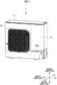
Fig. 1 is a front perspective view of an outdoor unit according to an embodiment of the present disclosure. -
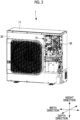
Fig. 2 is a view in a state where a service panel is removed inFig. 1 . -
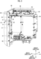
Fig. 3 is a front perspective view of the vicinity of a first electrical component box and a second electrical component box. -
Fig. 4 is a plan view of the vicinity of the first electrical component box and the second electrical component box. -
Fig. 5 is a plan view of the vicinity of the first electrical component box and the second electrical component box. -
Fig. 6 is a front perspective view of the vicinity of a holding structure. -
Fig. 7 is a front perspective view of the vicinity of the holding structure in a state where the first electrical component box is at a fixed position. -
Fig. 8 is a front view of the vicinity of a locking tab in a state where the first electrical component box is at the fixed position. -
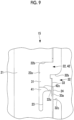
Fig. 9 is a front view of the vicinity of the locking tab in a state where the first electrical component box is at a rotation position. -
Fig. 10 is a front perspective view of the vicinity of the locking tab in a state where the first electrical component box is at the rotation position. -
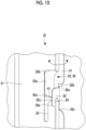
Fig. 11 is a front view of the vicinity of the locking tab when the first electrical component box is removed. - Hereinafter, a holding structure for an electrical component box, an outdoor unit, and a maintenance method according to an embodiment of the present disclosure will be described with reference to the drawings.
- A
holding structure 15 of the electrical component box is a structure applied to theoutdoor unit 1 of the air conditioning device. - The electrical component box is a structure in which an electronic circuit board or an electric device is accommodated or an electronic circuit board or an electric device is attached.
- As shown in
Fig. 1 , as is known, theoutdoor unit 1 is configured to accommodate a heat exchanger, a fan, a compressor, an expansion valve, and other auxiliary machines (not illustrated) inside ahousing 11 having a substantially rectangular parallelepiped outer shape. - A
front panel 20 that closes a heat exchange chamber and aservice panel 13 that closes a machine chamber are attached to a front surface (forward surface) of thehousing 11. - As shown in
Fig. 2 , when theservice panel 13 is removed, a plurality of electrical component boxes are accommodated above the machine chamber. In addition, a compressor or the like is accommodated below the machine chamber. - As shown in
Figs. 3 and4 , the plurality of electrical component boxes are provided in a multi-stage structure, for example, in a depth direction of theoutdoor unit 1. - The
outdoor unit 1 in the present embodiment includes, for example, a firstelectrical component box 30 installed on a front side in the depth direction and a secondelectrical component box 40 installed on a back side. - The first
electrical component box 30 has a form in which the firstelectrical component box 30 is housed in a room inside the secondelectrical component box 40 that has a substantially L shape in a plan view (refer toFig. 4 ) . - As a result, the electronic circuit board and the electric device required for controlling the air conditioning device are efficiently accommodated in the
outdoor unit 1. - However, it is necessary to easily access the second
electrical component box 40 installed behind the firstelectrical component box 30 during maintenance. - Therefore, as shown in
Figs. 4 and5 , in the present embodiment, the firstelectrical component box 30 is provided to be rotatable around an axis extending in a height direction with respect to the secondelectrical component box 40 like a door by theholding structure 15. - The
front panel 20, the firstelectrical component box 30, and the secondelectrical component box 40 are respectively formed of sheet metal. - The first
electrical component box 30 and the secondelectrical component box 40 do not necessarily have to be a "box type". - As shown in
Fig. 6 , an attachmentsheet metal part 21 is formed at an edge of thefront panel 20. - The attachment
sheet metal part 21 is a plate-shaped part extending in the height direction of theoutdoor unit 1 and along a width direction of theoutdoor unit 1. - An edge of the attachment
sheet metal part 21 is bent toward the front side in the depth direction. - An edge of the sheet metal forming the second
electrical component box 40 is bent to extend along the width direction of theoutdoor unit 1. - The bent plate-shaped part is a second
sheet metal part 41. The secondsheet metal part 41 extends in the height direction of theoutdoor unit 1 and along the width direction of theoutdoor unit 1. - An edge of the sheet metal forming the first
electrical component box 30 is bent to extend along the width direction of theoutdoor unit 1. - The bent plate-shaped part is a first
sheet metal part 31. In a case where the firstelectrical component box 30 is at a fixed position (to be described later), the firstsheet metal part 31 extends in the height direction of theoutdoor unit 1 and along the width direction of theoutdoor unit 1. - The
holding structure 15 is configured such that the attachmentsheet metal part 21, the secondsheet metal part 41, and the firstsheet metal part 31 are arranged in order from the front side in the depth direction of theoutdoor unit 1. - An
attachment notch 22 is formed in the attachmentsheet metal part 21. - The
attachment notch 22 is a recessed notch defined by aside edge 22a along the height direction, and anupper edge 22b and alower edge 22c along the width direction. - A
slit 23 that extends along an extending direction of theside edge 22a and extends downward in the height direction is formed at a base end (left end inFig. 6 ) of thelower edge 22c. The width dimension of theslit 23 is larger than the thickness dimension of alocking tab 33 to be described later. - A stopper (protrusion portion) 24 protruding upward in the height direction is formed at a tip of the
lower edge 22c (right end inFig. 6 ). - The second
sheet metal part 41 is formed with asecond notch 42. - The
second notch 42 is a recessed notch defined by aside edge 42a along the height direction, anupper edge 42b along the width direction, and alower edge 42c along the width direction. - The first
sheet metal part 31 is formed with afirst notch 32. - The
first notch 32 is a recessed notch defined by aside edge 32a along the height direction, anupper edge 32b along the width direction, and alower edge 32c along the width direction. - The
locking tab 33 bent to the front side in the depth direction is formed on theside edge 32a. - For example, the
locking tab 33 can be formed by leaving a part of a region of the sheet metal, which is unnecessary when thefirst notch 32 is punched out by a mold, and by folding the remaining part. - A hook-shaped
portion 33a protruding downward in the height direction is formed at a lower end portion of thelocking tab 33. - As shown in
Fig. 7 , when theoutdoor unit 1 is assembled (during non-maintenance), the attachmentsheet metal part 21, the secondsheet metal part 41, and the firstsheet metal part 31 are overlapped. - Specifically, the front surface of the second
sheet metal part 41 is overlapped on the back surface of the attachmentsheet metal part 21 to be in surface contact with the back surface of the attachmentsheet metal part 21, and the front surface of the firstsheet metal part 31 is overlapped on the back surface of the secondsheet metal part 41 to be in surface contact with the back surface of the secondsheet metal part 41. - As shown in
Fig. 8 , when theoutdoor unit 1 is viewed from the front, theattachment notch 22, thefirst notch 32, and thesecond notch 42 overlap each other. - At this time, the
lower edge 42c of thesecond notch 42 extends from theside edge 22a of theattachment notch 22 to a substantially intermediate point of thelower edge 22c across theslit 23. - The contour of the
lower edge 42c of thesecond notch 42 may smoothly incline (refer toFig. 8 ) or may linearly incline. - The
locking tab 33 enters thesecond notch 42 and theattachment notch 22 in a state where the attachmentsheet metal part 21, the secondsheet metal part 41, and the firstsheet metal part 31 are overlapped with each other. - At this time, as shown in
Figs. 7 and8 , in the firstelectrical component box 30, the side surface of thelocking tab 33 is adjacent to theside edge 22a of theattachment notch 22, and the lower end of the locking tab 33 (a portion excluding the hook-shapedportion 33a) abuts against thelower edge 42c of thesecond notch 42. In addition, the hook-shapedportion 33a is hooked on the front surface side of the secondsheet metal part 41. - The position of the first
electrical component box 30 in this state is referred to as a "fixed position". - The first
electrical component box 30 at the fixed position is fixed in this state. - Specifically, the first
electrical component box 30 is fixed to the secondelectrical component box 40 by ascrew 51 that fastens the firstsheet metal part 31 and the secondsheet metal part 41 to each other, and the secondelectrical component box 40 is fixed to thefront panel 20 by ascrew 52 that fastens the secondsheet metal part 41 and the attachmentsheet metal part 21 to each other. - At this time, the back surface of the second
sheet metal part 41 and the front surface of the firstsheet metal part 31 are brought into strong contact with each other by the fastening strength of thescrew 51. - In addition, as shown in
Figs. 3 and4 , the firstelectrical component box 30 and the secondelectrical component box 40 may be connected to each other by a reinforcingmember 53. - The reinforcing
member 53 is fastened to the firstelectrical component box 30 by ascrew 54 and is fastened to the secondelectrical component box 40 by ascrew 55. - As shown in
Figs. 9 and10 , the firstelectrical component box 30 can be moved (movement step) from the fixed position by releasing (releasing step) the fixation by thescrew 51. - At this time, the first
electrical component box 30 is moved, so that thelocking tab 33 of the firstsheet metal part 31 is separated from theside edge 22a of theattachment notch 22 and is positioned on a tip side of thelower edge 22c. - The position of the first
electrical component box 30 in this state is referred to as a "rotation position". - When the first
electrical component box 30 moves from the fixed position to the rotation position, astopper 24 prevents thelocking tab 33 from falling off from theattachment notch 22. In addition, the hook-shapedportion 33a also prevents thelocking tab 33 from falling off from theattachment notch 22. - The first
electrical component box 30 at the rotation position can be rotated around the axis extending in the height direction with a contact location between the lower end of thelocking tab 33 and thelower edge 22c of theattachment notch 22 as a fulcrum (rotation step). - That is, the first
electrical component box 30 can be rotated with respect to thefront panel 20 or the secondelectrical component box 40 like a door by the sheet metal processing without using a special component such as a hinge. In this manner, the secondelectrical component box 40 on the back side of the firstelectrical component box 30 can be accessed to perform maintenance or the like. - As shown in
Figs. 8 and9 , when the holdingstructure 15 is viewed from the front in the depth direction, in a case where thelower edge 42c of thesecond notch 42 extends from theside edge 22a of theattachment notch 22 to thelower edge 22c, in the movement step of the firstelectrical component box 30, the lower end of thelocking tab 33 can be smoothly guided to thelower edge 22c of theattachment notch 22 by moving the lower end of thelocking tab 33 along thelower edge 42c of thesecond notch 42. - In a case where the first
electrical component box 30 is required to be completely removed from theoutdoor unit 1, the firstelectrical component box 30 may be lifted such that thelocking tab 33 rides over thestopper 24 as shown inFig. 11 . - According to the present embodiment, the following effects are achieved.
- The first
electrical component box 30 takes a fixed position where thelocking tab 33 is fixed in a state where thelocking tab 33 enters theattachment notch 22 and thesecond notch 42 and is adjacent to the side edge of theattachment notch 22, and a rotation position where thelocking tab 33 abuts against thelower edge 22c of theattachment notch 22, and the firstsheet metal part 31 is overlapped on the secondsheet metal part 41 and abuts against the secondsheet metal part 41 in a state where the firstelectrical component box 30 is at the fixed position. Therefore, the firstelectrical component box 30 can be firmly fixed in a state where the firstelectrical component box 30 is positioned with respect to the secondelectrical component box 40 when the firstelectrical component box 30 is at the fixed position. - In addition, when the fixation is released and the first
electrical component box 30 is at the rotation position, the firstelectrical component box 30 can be rotated around an axis extending in the height direction with the contact location between the lockingtab 33 and thelower edge 22c of theattachment notch 22 as a fulcrum. That is, the firstelectrical component box 30 can be rotated with respect to thefront panel 20 or the secondelectrical component box 40 without using a special component such as a hinge. In this manner, the room behind the firstelectrical component box 30 can be easily accessed. - In addition, since the
front panel 20 and the firstelectrical component box 30 are not connected to each other by a hinge or the like, the firstelectrical component box 30 can be easily removed. - In addition, since the
lower edge 42c of thesecond notch 42 extends from theside edge 22a of theattachment notch 22 to thelower edge 22c of theattachment notch 22, thelocking tab 33 that abuts against theside edge 22a of theattachment notch 22 can be guided to thelower edge 22c of theattachment notch 22 while being aligned with thelower edge 42c of thesecond notch 42. - In addition, when the first
electrical component box 30 is at the fixed position, thelocking tab 33 abuts against thelower edge 42c of thesecond notch 42. Therefore, the firstelectrical component box 30 can be firmly fixed in a state where the firstelectrical component box 30 is positioned at a plurality of locations in addition to the contact between the firstsheet metal part 31 and the secondsheet metal part 41. - In addition, the attachment
sheet metal part 21 has theslits 23, and the width dimension of theslits 23 is larger than the thickness dimension of thelocking tab 33. Therefore, when thefront panel 20 is attached to theoutdoor unit 1 in a state where the firstelectrical component box 30 and the secondelectrical component box 40 are installed, thefront panel 20 can be attached without interfering with thelocking tab 33 formed in the firstsheet metal part 31. - In addition, since the attachment
sheet metal part 21 has thestopper 24, it is possible to prevent thelocking tab 33 of the firstelectrical component box 30 at the rotation position from easily falling off from theattachment notch 22. - The number of the electrical component boxes arranged in the depth direction of the
outdoor unit 1 may be one or may be two or more. - The holding structure for the electrical component box, the outdoor unit, and the maintenance method according to the above-described embodiment are understood as follows, for example.
- That is, a holding structure (15) for an electrical component box according to an embodiment of the present disclosure includes: a front panel (20) that is formed with an attachment sheet metal part (21) extending in a height direction of an outdoor unit (1); a first electrical component box (30) that is formed with a first sheet metal part (31) provided on a back side of the attachment sheet metal part in a depth direction of the outdoor unit; and a second electrical component box (40) that is installed on the back side of the first electrical component box in the depth direction and is formed with a second sheet metal part (41) provided between the attachment sheet metal part and the first sheet metal part in the depth direction, in which the first sheet metal part has a locking tab (33) extending to a front side in the depth direction, the attachment sheet metal part has an attachment notch (22) into which the locking tab enters from a width direction of the outdoor unit, the second sheet metal part has a second notch (42) into which the locking tab enters from the width direction, the first electrical component box takes a fixed position at which the locking tab is fixed in a state of entering the attachment notch and the second notch and being adjacent to a side edge (22a) of the attachment notch, and a rotation position at which the locking tab abuts against a lower edge (22c) of the attachment notch, and when the first electrical component box is at the fixed position, the first sheet metal part abuts against the second sheet metal part on a surface, in a state of being overlapped with the second sheet metal part.
- According to a holding structure for an electrical component box of the present aspect, the holding structure includes: a front panel, which is formed with an attachment sheet metal part extending in a height direction of an outdoor unit; a first electrical component box that is formed with a first sheet metal part provided on a back side of the attachment sheet metal part in a depth direction of the outdoor unit; and a second electrical component box (40) that is installed on the back side of the first electrical component box in the depth direction and is formed with a second sheet metal part provided between the attachment sheet metal part and the first sheet metal part in the depth direction, in which the first sheet metal part has a locking tab extending to a front side in the depth direction, the attachment sheet metal part has an attachment notch into which the locking tab enters from a width direction of the outdoor unit, the second sheet metal part has a second notch into which the locking tab enters from the width direction, the first electrical component box takes a fixed position at which the locking tab is fixed in a state of entering the attachment notch and the second notch and being adjacent to a side edge of the attachment notch, and a rotation position at which the locking tab abuts against a lower edge of the attachment notch, and when the first electrical component box is at the fixed position, the first sheet metal part abuts against the second sheet metal part on a surface, in a state of being overlapped with the second sheet metal part. Therefore, when the first electrical component box is at the fixed position, the first electrical component box can be firmly fixed in a state where the first electrical component box is positioned with respect to the second electrical component box.
- In addition, when the fixation is released and the first electrical component box is at the rotation position, the first electrical component box can be rotated around the axis extending in the height direction with the contact location between the locking tab and the lower edge of the attachment notch as a fulcrum. That is, the first electrical component box can be rotated with respect to the front panel without using a special component such as a hinge. In this manner, the room behind the first electrical component box can be easily accessed.
- In addition, since the front panel and the first electrical component box are not connected to each other by a hinge or the like, the first electrical component box can be easily removed.
- In addition, in the holding structure for an electrical component box according to the embodiment of the present disclosure, when the attachment sheet metal part and the second sheet metal part in a state of being overlapped with each other in the depth direction are viewed from a front in the depth direction, a lower edge (42c) of the second notch may extend from the side edge of the attachment notch to the lower edge of the attachment notch.
- According to the holding structure for an electrical component box of the present aspect, when the attachment sheet metal part and the second sheet metal part in a state of being overlapped with each other in the depth direction are viewed from a front in the depth direction, the lower edge of the second notch may extend from the side edge of the attachment notch to the lower edge of the attachment notch. Therefore, the locking tab that abuts against the side edge of the attachment notch can be guided to the lower edge of the attachment notch while being aligned with the lower edge of the second notch.
- In addition, in the holding structure for an electrical component box according to the embodiment of the present disclosure, when the first electrical component box is at the fixed position, the locking tab may abut against the lower edge of the second notch.
- According to the holding structure for an electrical component box of the present aspect, when the first electrical component box is at the fixed position, the locking tab abuts against the lower edge of the second notch. Therefore, the first electrical component box can be firmly fixed in a state where the first electrical component box is positioned at a plurality of locations in addition to the contact between the first
sheet metal part 31 and the secondsheet metal part 41. - In addition, in the holding structure for an electrical component box according to the embodiment of the present disclosure, the attachment sheet metal part may have a slit (23) that extends downward in the height direction along the side edge from the lower edge of the attachment notch, and a width dimension of the slit is larger than a thickness dimension of the locking tab.
- According to the holding structure for an electrical component box of the present aspect, the attachment sheet metal part has a slit that extends downward in the height direction along the side edge from the lower edge of the attachment notch, and a width dimension of the slit is larger than a thickness dimension of the locking tab. Therefore, the front panel can be attached without interfering with the locking tab formed in the first sheet metal part.
- In addition, in the holding structure for an electrical component box according to the embodiment of the present disclosure, the attachment sheet metal part may include a protrusion portion (24) that extends upward in the height direction from an end portion of the lower edge of the attachment notch.
- According to the holding structure for an electrical component box of the present aspect, the attachment sheet metal part includes a protrusion portion (24) that extends upward in the height direction from an end portion of the lower edge of the attachment notch. Therefore, it is possible to prevent the locking tab of the first electrical component box at the rotation position from easily falling off from the attachment notch.
- In addition, an outdoor unit according to the embodiment of the present disclosure includes: the holding structure for an electrical component box; a housing to which the front panel is attached; and a fan accommodated in a room defined by the front panel and the housing.
- In addition, according to the present disclosure, there is provided a maintenance method for maintaining a holding structure for an electrical component box, the holding structure including a front panel that is formed with an attachment sheet metal part extending in a height direction of an outdoor unit, a first electrical component box that is formed with a first sheet metal part provided on a back side of the attachment sheet metal part in a depth direction of the outdoor unit, and a second electrical component box that is installed on the back side of the first electrical component box in the depth direction and is formed with a second sheet metal part provided between the attachment sheet metal part and the first sheet metal part in the depth direction, in which the first sheet metal part has a locking tab extending to a front side in the depth direction, the attachment sheet metal part has an attachment notch into which the locking tab enters from a width direction of the outdoor unit, the second sheet metal part has a second notch into which the locking tab enters from the width direction, the first electrical component box takes a fixed position at which the locking tab is fixed in a state of entering the attachment notch and the second notch and being adjacent to a side edge of the attachment notch, and a rotation position at which the locking tab abuts against a lower edge of the attachment notch, and when the first electrical component box is at the fixed position, the first sheet metal part abuts against the second sheet metal part on a surface, in a state of being overlapped with the second sheet metal part, the maintenance method including: a releasing step of releasing the fixation of the first electrical component box fixed at the fixed position; a movement step of moving the first electrical component box to the rotation position; and a rotation step of rotating the first electrical component box around an axis extending in the height direction at the rotation position.
- In addition, in the holding structure for electrical component box according to the embodiment of the present disclosure, in the holding structure for an electrical component box in which the lower edge of the second notch extends from the side edge of the attachment notch to the lower edge of the attachment notch when the attachment sheet metal part and the second sheet metal part in a state of being overlapped with each other in the depth direction are viewed in the depth direction, in the movement step, the locking tab is moved along the lower edge of the second notch.
- In addition, in the holding structure for an electrical component box according to the embodiment of the present disclosure includes a removal step of removing, in the holding structure for an electrical component box in which the attachment sheet metal part includes a protrusion portion that extends upward in the height direction from an end portion of the lower edge of the attachment notch, the first electrical component box from the attachment notch by causing the locking tab to ride over the protrusion portion.
-
- 1: outdoor unit
- 11: housing
- 13: service panel
- 15: holding structure
- 20: front panel
- 21: attachment sheet metal part
- 22: attachment notch
- 22a: side edge
- 22b: upper edge
- 22c: lower edge
- 23: slit
- 24: stopper (protrusion portion)
- 30: first electrical component box
- 31: first sheet metal part
- 32: first notch
- 32a: side edge
- 32b: upper edge
- 32c: lower edge
- 33: locking tab
- 33a: hook-shaped portion
- 40: second electrical component box
- 41: second sheet metal part
- 42: second notch
- 42a: side edge
- 42b: upper edge
- 42c lower edge (inducer edge)
- 51: screw
- 52: screw
- 53: reinforcing member
- 54: screw
- 55: screw
Claims (9)
- A holding structure for an electrical component box, comprising:a front panel that is formed with an attachment sheet metal part extending in a height direction of an outdoor unit;a first electrical component box that is formed with a first sheet metal part provided on a back side of the attachment sheet metal part in a depth direction of the outdoor unit; anda second electrical component box that is installed on the back side of the first electrical component box in the depth direction and is formed with a second sheet metal part provided between the attachment sheet metal part and the first sheet metal part in the depth direction,wherein the first sheet metal part has a locking tab extending to a front side in the depth direction,the attachment sheet metal part has an attachment notch into which the locking tab enters from a width direction of the outdoor unit,the second sheet metal part has a second notch into which the locking tab enters from the width direction,the first electrical component box takes a fixed position at which the locking tab is fixed in a state of entering the attachment notch and the second notch and being adjacent to a side edge of the attachment notch, and a rotation position at which the locking tab abuts against a lower edge of the attachment notch, andwhen the first electrical component box is at the fixed position, the first sheet metal part abuts against the second sheet metal part on a surface, in a state of being overlapped with the second sheet metal part.
- The holding structure for an electrical component box according to Claim 1,
wherein when the attachment sheet metal part and the second sheet metal part in a state of being overlapped with each other in the depth direction are viewed from a front in the depth direction, the lower edge of the second notch extends from the side edge of the attachment notch to the lower edge of the attachment notch. - The holding structure for an electrical component box according to Claim 1 or 2,
wherein when the first electrical component box is at the fixed position, the locking tab abuts against the lower edge of the second notch. - The holding structure for an electrical component box according to any one of Claims 1 to 3,wherein the attachment sheet metal part has a slit that extends downward in the height direction along the side edge from the lower edge of the attachment notch, anda width dimension of the slit is larger than a thickness dimension of the locking tab.
- The holding structure for an electrical component box according to any one of Claims 1 to 4,
wherein the attachment sheet metal part includes a protrusion portion that extends upward in the height direction from an end portion of the lower edge of the attachment notch. - An outdoor unit comprising:the holding structure for an electrical component box according to any one of Claims 1 to 5;a housing to which the front panel is attached; anda fan accommodated in a room defined by the front panel and the housing.
- A maintenance method for maintaining a holding structure for an electrical component box, the holding structure including a front panel that is formed with an attachment sheet metal part extending in a height direction of an outdoor unit, a first electrical component box that is formed with a first sheet metal part provided on a back side of the attachment sheet metal part in a depth direction of the outdoor unit, and a second electrical component box that is installed on the back side of the first electrical component box in the depth direction and is formed with a second sheet metal part provided between the attachment sheet metal part and the first sheet metal part in the depth direction, in which the first sheet metal part has a locking tab extending to a front side in the depth direction, the attachment sheet metal part has an attachment notch into which the locking tab enters from a width direction of the outdoor unit, the second sheet metal part has a second notch into which the locking tab enters from the width direction, the first electrical component box takes a fixed position at which the locking tab is fixed in a state of entering the attachment notch and the second notch and being adjacent to a side edge of the attachment notch, and a rotation position at which the locking tab abuts against a lower edge of the attachment notch, and when the first electrical component box is at the fixed position, the first sheet metal part abuts against the second sheet metal part on a surface, in a state of being overlapped with the second sheet metal part, the maintenance method comprising:a releasing step of releasing the fixation of the first electrical component box fixed at the fixed position;a movement step of moving the first electrical component box to the rotation position; anda rotation step of rotating the first electrical component box around an axis extending in the height direction at the rotation position.
- The maintenance method according to Claim 7,
wherein, in the holding structure for an electrical component box in which a lower edge of the second notch extends from the side edge of the attachment notch to the lower edge of the attachment notch when the attachment sheet metal part and the second sheet metal part in a state of being overlapped with each other in the depth direction are viewed in the depth direction, in the movement step, the locking tab is moved along the lower edge of the second notch. - The maintenance method according to Claim 7 or 8, further comprising:
a removal step of removing, in the holding structure for an electrical component box in which the attachment sheet metal part includes a protrusion portion that extends upward in the height direction from an end portion of the lower edge of the attachment notch, the first electrical component box from the attachment notch by causing the locking tab to ride over the protrusion portion.
Applications Claiming Priority (2)
| Application Number | Priority Date | Filing Date | Title |
|---|---|---|---|
| JP2022018517A JP7314332B1 (en) | 2022-02-09 | 2022-02-09 | Holding structure of electrical box, outdoor unit, and maintenance method |
| PCT/JP2022/042507 WO2023153038A1 (en) | 2022-02-09 | 2022-11-16 | Holding structure for electrical component box, outdoor unit, and maintenance method |
Publications (2)
| Publication Number | Publication Date |
|---|---|
| EP4459195A1 true EP4459195A1 (en) | 2024-11-06 |
| EP4459195A4 EP4459195A4 (en) | 2025-04-09 |
Family
ID=87428122
Family Applications (1)
| Application Number | Title | Priority Date | Filing Date |
|---|---|---|---|
| EP22926054.2A Pending EP4459195A4 (en) | 2022-02-09 | 2022-11-16 | Supporting structure for an electrical component box, outdoor unit, and maintenance procedures |
Country Status (4)
| Country | Link |
|---|---|
| EP (1) | EP4459195A4 (en) |
| JP (1) | JP7314332B1 (en) |
| CN (1) | CN118679351A (en) |
| WO (1) | WO2023153038A1 (en) |
Families Citing this family (2)
| Publication number | Priority date | Publication date | Assignee | Title |
|---|---|---|---|---|
| WO2025083749A1 (en) * | 2023-10-16 | 2025-04-24 | 三菱電機株式会社 | Water heater |
| JP2026027824A (en) * | 2024-08-06 | 2026-02-19 | 三菱重工サーマルシステムズ株式会社 | Retaining structure and outdoor unit |
Family Cites Families (6)
| Publication number | Priority date | Publication date | Assignee | Title |
|---|---|---|---|---|
| JP5471783B2 (en) | 2010-04-30 | 2014-04-16 | 株式会社富士通ゼネラル | Air conditioner outdoor unit |
| JP5669650B2 (en) * | 2011-03-31 | 2015-02-12 | 三菱電機株式会社 | Air conditioner outdoor unit |
| JP2014066462A (en) | 2012-09-26 | 2014-04-17 | Mitsubishi Heavy Ind Ltd | Control unit for air conditioner |
| KR102168620B1 (en) * | 2014-02-03 | 2020-10-21 | 엘지전자 주식회사 | Outdoor unit for air conditoiner |
| JP7227552B2 (en) | 2018-02-21 | 2023-02-22 | 株式会社富士通ゼネラル | outdoor unit of air conditioner |
| KR102076652B1 (en) * | 2018-03-12 | 2020-02-12 | 엘지전자 주식회사 | An outdoor unit for an air conditioner |
-
2022
- 2022-02-09 JP JP2022018517A patent/JP7314332B1/en active Active
- 2022-11-16 CN CN202280090798.6A patent/CN118679351A/en active Pending
- 2022-11-16 WO PCT/JP2022/042507 patent/WO2023153038A1/en not_active Ceased
- 2022-11-16 EP EP22926054.2A patent/EP4459195A4/en active Pending
Also Published As
| Publication number | Publication date |
|---|---|
| JP7314332B1 (en) | 2023-07-25 |
| EP4459195A4 (en) | 2025-04-09 |
| CN118679351A (en) | 2024-09-20 |
| WO2023153038A1 (en) | 2023-08-17 |
| JP2023116009A (en) | 2023-08-22 |
Similar Documents
| Publication | Publication Date | Title |
|---|---|---|
| US6244953B1 (en) | Electronic device fan mounting system | |
| CN106524333B (en) | Mounting structure of valve bracket and air conditioner outdoor unit | |
| JP7314332B1 (en) | Holding structure of electrical box, outdoor unit, and maintenance method | |
| JP6656394B2 (en) | Air conditioner outdoor unit | |
| US6730845B1 (en) | Electric component box with removable cover | |
| KR0184697B1 (en) | Electrical parts box of air conditioner | |
| JP7138782B2 (en) | outdoor unit of air conditioner | |
| EP3748242A1 (en) | Outdoor unit for air conditioner | |
| CN112616269A (en) | Automatically controlled box and air conditioner | |
| US6404651B1 (en) | Computer expansion card shield retention device | |
| EP2927616B1 (en) | Air conditioner | |
| CN110848946B (en) | Electric control box assembly and air conditioner | |
| WO2019073547A1 (en) | Air-conditioner outdoor unit | |
| JP2000023331A (en) | Fixing structure of electrical junction box | |
| CN216346937U (en) | Electric control device of indoor unit of air conditioner | |
| EP3822128B1 (en) | Electric connection box | |
| EP4306868A1 (en) | Outdoor unit | |
| JP7378573B2 (en) | Air conditioner indoor unit | |
| JP6897211B2 (en) | Ceiling-embedded indoor unit of air conditioner | |
| US20260068078A1 (en) | Adaptable fan guard | |
| JP2023518047A (en) | Computers and how to install expansion cards in computers | |
| JP5065930B2 (en) | Power supply device for slide structure and assembly method thereof | |
| JPH09184639A (en) | Air conditioner | |
| CN215260408U (en) | An electric control box assembly and an air conditioner | |
| KR100366512B1 (en) | A mounting board of control box for air conditioner |
Legal Events
| Date | Code | Title | Description |
|---|---|---|---|
| STAA | Information on the status of an ep patent application or granted ep patent |
Free format text: STATUS: THE INTERNATIONAL PUBLICATION HAS BEEN MADE |
|
| PUAI | Public reference made under article 153(3) epc to a published international application that has entered the european phase |
Free format text: ORIGINAL CODE: 0009012 |
|
| STAA | Information on the status of an ep patent application or granted ep patent |
Free format text: STATUS: REQUEST FOR EXAMINATION WAS MADE |
|
| 17P | Request for examination filed |
Effective date: 20240731 |
|
| AK | Designated contracting states |
Kind code of ref document: A1 Designated state(s): AL AT BE BG CH CY CZ DE DK EE ES FI FR GB GR HR HU IE IS IT LI LT LU LV MC ME MK MT NL NO PL PT RO RS SE SI SK SM TR |
|
| A4 | Supplementary search report drawn up and despatched |
Effective date: 20250312 |
|
| RIC1 | Information provided on ipc code assigned before grant |
Ipc: F24F 1/56 20110101ALI20250306BHEP Ipc: F24F 1/54 20110101ALI20250306BHEP Ipc: F24F 11/89 20180101ALI20250306BHEP Ipc: F24F 1/22 20110101AFI20250306BHEP |
|
| DAV | Request for validation of the european patent (deleted) | ||
| DAX | Request for extension of the european patent (deleted) | ||
| GRAP | Despatch of communication of intention to grant a patent |
Free format text: ORIGINAL CODE: EPIDOSNIGR1 |
|
| STAA | Information on the status of an ep patent application or granted ep patent |
Free format text: STATUS: GRANT OF PATENT IS INTENDED |
|
| RIC1 | Information provided on ipc code assigned before grant |
Ipc: F24F 1/22 20110101AFI20251204BHEP Ipc: F24F 11/89 20180101ALI20251204BHEP Ipc: F24F 1/54 20110101ALI20251204BHEP Ipc: F24F 1/56 20110101ALI20251204BHEP |
|
| INTG | Intention to grant announced |
Effective date: 20260105 |
|
| GRAS | Grant fee paid |
Free format text: ORIGINAL CODE: EPIDOSNIGR3 |
|
| GRAA | (expected) grant |
Free format text: ORIGINAL CODE: 0009210 |
|
| STAA | Information on the status of an ep patent application or granted ep patent |
Free format text: STATUS: THE PATENT HAS BEEN GRANTED |