EP4459189A1 - Combustor for gas turbines - Google Patents
Combustor for gas turbines Download PDFInfo
- Publication number
- EP4459189A1 EP4459189A1 EP22915941.3A EP22915941A EP4459189A1 EP 4459189 A1 EP4459189 A1 EP 4459189A1 EP 22915941 A EP22915941 A EP 22915941A EP 4459189 A1 EP4459189 A1 EP 4459189A1
- Authority
- EP
- European Patent Office
- Prior art keywords
- liner
- shell
- wall structure
- combustor
- seal wall
- Prior art date
- Legal status (The legal status is an assumption and is not a legal conclusion. Google has not performed a legal analysis and makes no representation as to the accuracy of the status listed.)
- Pending
Links
Images



Classifications
-
- F—MECHANICAL ENGINEERING; LIGHTING; HEATING; WEAPONS; BLASTING
- F23—COMBUSTION APPARATUS; COMBUSTION PROCESSES
- F23R—GENERATING COMBUSTION PRODUCTS OF HIGH PRESSURE OR HIGH VELOCITY, e.g. GAS-TURBINE COMBUSTION CHAMBERS
- F23R3/00—Continuous combustion chambers using liquid or gaseous fuel
- F23R3/005—Combined with pressure or heat exchangers
-
- F—MECHANICAL ENGINEERING; LIGHTING; HEATING; WEAPONS; BLASTING
- F23—COMBUSTION APPARATUS; COMBUSTION PROCESSES
- F23R—GENERATING COMBUSTION PRODUCTS OF HIGH PRESSURE OR HIGH VELOCITY, e.g. GAS-TURBINE COMBUSTION CHAMBERS
- F23R3/00—Continuous combustion chambers using liquid or gaseous fuel
- F23R3/002—Wall structures
-
- F—MECHANICAL ENGINEERING; LIGHTING; HEATING; WEAPONS; BLASTING
- F02—COMBUSTION ENGINES; HOT-GAS OR COMBUSTION-PRODUCT ENGINE PLANTS
- F02C—GAS-TURBINE PLANTS; AIR INTAKES FOR JET-PROPULSION PLANTS; CONTROLLING FUEL SUPPLY IN AIR-BREATHING JET-PROPULSION PLANTS
- F02C7/00—Features, components parts, details or accessories, not provided for in, or of interest apart form groups F02C1/00 - F02C6/00; Air intakes for jet-propulsion plants
- F02C7/12—Cooling of plants
- F02C7/16—Cooling of plants characterised by cooling medium
- F02C7/18—Cooling of plants characterised by cooling medium the medium being gaseous, e.g. air
-
- F—MECHANICAL ENGINEERING; LIGHTING; HEATING; WEAPONS; BLASTING
- F23—COMBUSTION APPARATUS; COMBUSTION PROCESSES
- F23R—GENERATING COMBUSTION PRODUCTS OF HIGH PRESSURE OR HIGH VELOCITY, e.g. GAS-TURBINE COMBUSTION CHAMBERS
- F23R3/00—Continuous combustion chambers using liquid or gaseous fuel
- F23R3/02—Continuous combustion chambers using liquid or gaseous fuel characterised by the air-flow or gas-flow configuration
- F23R3/04—Air inlet arrangements
- F23R3/06—Arrangement of apertures along the flame tube
-
- F—MECHANICAL ENGINEERING; LIGHTING; HEATING; WEAPONS; BLASTING
- F23—COMBUSTION APPARATUS; COMBUSTION PROCESSES
- F23R—GENERATING COMBUSTION PRODUCTS OF HIGH PRESSURE OR HIGH VELOCITY, e.g. GAS-TURBINE COMBUSTION CHAMBERS
- F23R3/00—Continuous combustion chambers using liquid or gaseous fuel
- F23R3/42—Continuous combustion chambers using liquid or gaseous fuel characterised by the arrangement or form of the flame tubes or combustion chambers
- F23R3/50—Combustion chambers comprising an annular flame tube within an annular casing
-
- F—MECHANICAL ENGINEERING; LIGHTING; HEATING; WEAPONS; BLASTING
- F23—COMBUSTION APPARATUS; COMBUSTION PROCESSES
- F23R—GENERATING COMBUSTION PRODUCTS OF HIGH PRESSURE OR HIGH VELOCITY, e.g. GAS-TURBINE COMBUSTION CHAMBERS
- F23R2900/00—Special features of, or arrangements for continuous combustion chambers; Combustion processes therefor
- F23R2900/00012—Details of sealing devices
-
- F—MECHANICAL ENGINEERING; LIGHTING; HEATING; WEAPONS; BLASTING
- F23—COMBUSTION APPARATUS; COMBUSTION PROCESSES
- F23R—GENERATING COMBUSTION PRODUCTS OF HIGH PRESSURE OR HIGH VELOCITY, e.g. GAS-TURBINE COMBUSTION CHAMBERS
- F23R2900/00—Special features of, or arrangements for continuous combustion chambers; Combustion processes therefor
- F23R2900/03041—Effusion cooled combustion chamber walls or domes
-
- F—MECHANICAL ENGINEERING; LIGHTING; HEATING; WEAPONS; BLASTING
- F23—COMBUSTION APPARATUS; COMBUSTION PROCESSES
- F23R—GENERATING COMBUSTION PRODUCTS OF HIGH PRESSURE OR HIGH VELOCITY, e.g. GAS-TURBINE COMBUSTION CHAMBERS
- F23R2900/00—Special features of, or arrangements for continuous combustion chambers; Combustion processes therefor
- F23R2900/03043—Convection cooled combustion chamber walls with means for guiding the cooling air flow
-
- F—MECHANICAL ENGINEERING; LIGHTING; HEATING; WEAPONS; BLASTING
- F23—COMBUSTION APPARATUS; COMBUSTION PROCESSES
- F23R—GENERATING COMBUSTION PRODUCTS OF HIGH PRESSURE OR HIGH VELOCITY, e.g. GAS-TURBINE COMBUSTION CHAMBERS
- F23R2900/00—Special features of, or arrangements for continuous combustion chambers; Combustion processes therefor
- F23R2900/03044—Impingement cooled combustion chamber walls or subassemblies
-
- Y—GENERAL TAGGING OF NEW TECHNOLOGICAL DEVELOPMENTS; GENERAL TAGGING OF CROSS-SECTIONAL TECHNOLOGIES SPANNING OVER SEVERAL SECTIONS OF THE IPC; TECHNICAL SUBJECTS COVERED BY FORMER USPC CROSS-REFERENCE ART COLLECTIONS [XRACs] AND DIGESTS
- Y02—TECHNOLOGIES OR APPLICATIONS FOR MITIGATION OR ADAPTATION AGAINST CLIMATE CHANGE
- Y02T—CLIMATE CHANGE MITIGATION TECHNOLOGIES RELATED TO TRANSPORTATION
- Y02T50/00—Aeronautics or air transport
- Y02T50/60—Efficient propulsion technologies, e.g. for aircraft
Definitions
- the present disclosure relates to a combustor of a gas turbine.
- a liner defining a combustion chamber of the combustor may be formed by a ceramic matrix composite (CMC) instead of metal.
- CMC ceramic matrix composite
- the CMC is lighter than metal. Since the heatproof temperature of the CMC is high, the amount of cooling air can be reduced while realizing high-temperature high-pressure combustion. Therefore, when the liner is made of the CMC, the fuel efficiency of the gas turbine can be improved.
- PTL 1 discloses that a liner (heat shield) located at a radially inner side of a shell of the combustor is cooled.
- a cooling chamber is located between the shell and the liner.
- the shell includes an opening through which cooling air is introduced into the cooling chamber.
- the liner includes a cooling hole through which the cooling air flows out from the cooling chamber to the combustion chamber.
- An object of the present disclosure is to seal a cooling chamber of a combustor of a gas turbine while facilitating the manufacture of a CMC liner.
- a combustor of a gas turbine includes: a shell including metal; a liner located inside the shell and including a ceramic matrix composite, the liner including an inner surface defining a combustion chamber, an outer surface facing a side opposite to a side where the combustion chamber is located, and at least one cooling hole that is open toward the combustion chamber; and a cooling chamber defined between the shell and the liner.
- the shell includes a tubular shell main body and a seal wall structure projecting from an inner surface of the shell main body toward the liner.
- the seal wall structure projects from the shell made of metal, and the CMC liner is prevented from becoming complex. Therefore, the cooling chamber can be sealed by the seal wall structure while facilitating the manufacture of the CMC liner.
- An axis X of a gas turbine 1 is the same as an axis of a combustor 2.
- a direction orthogonal to the axis X of the combustor 2 is referred to as a radial direction R of the combustor 2
- a direction around the axis X is referred to as a circumferential direction C of the combustor 2.
- a flow direction F in a combustion chamber 9 a side where fuel injectors 10 are located is referred to as an upstream side, and a side where an exhaust port 9a is located is referred to as a downstream side.
- FIG. 1 is a schematic diagram showing the combustor 2 of the gas turbine 1 according to the embodiment when viewed from the downstream side in the flow direction.
- the combustor 2 is a combustor of the gas turbine 1 used as an aircraft engine.
- the combustor 2 mixes compressed air, supplied from a compressor, with fuel to generate a fuel-air mixture, and combusts the fuel-air mixture.
- the combustor 2 generates a high-temperature high-pressure combustion gas.
- the generated combustion gas is supplied to a turbine to drive the turbine.
- the combustor 2 has a tubular shape and for example, is of an annular type formed in an annular shape surrounding the axis X of the gas turbine 1.
- the combustor 2 may be of a type other than the annular type.
- the combustor 2 includes a casing 3.
- the casing 3 includes an annular outer casing 4 and an annular inner casing 5 which is concentrically located inside the outer casing 4.
- An annular internal space is defined by the outer casing 4 and the inner casing 5.
- An inside of the combustor 2 denotes an inside of the outer casing 4 in the radial direction R and an outside of the inner casing 5 in the radial direction R.
- a shell 6 is located in the annular internal space of the casing 3 and is a combustion liner that is concentric with the casing 3.
- the shell 6 is made of metal.
- the shell 6 includes an annular outer shell 7 and an annular inner shell 8 which is concentrically located inside the outer shell 7.
- the shell 6 defines an annular space by the outer shell 7 and the inner shell 8.
- the annular space surrounded by the outer shell 7 and the inner shell 8 is utilized as the combustion chamber 9.
- An inside of the shell 6 denotes an inside of the outer shell 7 in the radial direction R and an outside of the inner shell 8 in the radial direction R.
- Fuel injectors 10 that inject the fuel into the combustion chamber 9 are located annularly along the combustion chamber 9 at the upstream side of the combustion chamber 9.
- the fuel injectors 10 are lined up in the circumferential direction C on a virtual circle that is concentric with the shell 6.
- Ignition plugs 11 are located at the shell 6 and generate sparks to ignite the fuel-air mixture in the combustion chamber 9 at the start of the gas turbine 1.
- An outer liner 14 is located inside the tubular outer shell 7 in the radial direction R.
- An inner liner 15 is located outside the tubular inner shell 8 in the radial direction R.
- the outer liner 14 may be an assembly of panels 18 which are adjacently lined up in the circumferential direction to have a tubular shape.
- the inner liner 15 may be an assembly of panels 19 which are adjacently lined up in the circumferential direction to have a tubular shape.
- One or each of the outer liner 14 and the inner liner 15 may be a tubular body formed in a tubular shape by integral molding without being divided into panels lined up in the circumferential direction.
- FIG. 2 is a sectional view taken along line II-II of FIG. 1 showing the combustor 2.
- a diffuser 12 is located at an upstream portion of the casing 3 and takes the compressed air, generated by the compressor, in the casing 3.
- the fuel injectors 10 are supported by a stem 13 fixed to the casing 3. Part of the compressed air which has been taken in the casing 3 is supplied to the fuel injectors 10 for combustion.
- the rest of the compressed air which has been taken in the casing 3 cools an outer surface of the shell 6, and part of the rest of the compressed air which has been taken in the casing is supplied as cooling air into the shell 6 through openings 20c (see FIG. 3 ) of the shell 6.
- the tubular outer liner 14 as a liner is located inside the tubular outer shell 7 in the radial direction R.
- the tubular inner liner 15 as a liner is located outside the tubular inner shell 8 in the radial direction R.
- the outer liner 14 and the inner liner 15 are spaced apart from the shell 6.
- the outer liner 14 and the inner liner 15 define the combustion chamber 9.
- the gas which has been combusted in the combustion chamber 9 is discharged toward the turbine through the exhaust port 9a which is defined by a downstream end 14e of the outer shell 7 in the flow direction F and a downstream end 15e of the inner shell 8 in the flow direction F.
- the outer liner 14 and the inner liner 15 are made of a ceramic matrix composite (CMC). There is a gap between the outer shell 7 and each of both ends 14d and 14e of the outer liner 14 in the flow direction F, and there is also a gap between the inner shell 8 and each of both ends 15d and 15e of the inner liner 15 in the flow direction F.
- CMC ceramic matrix composite
- FIG. 3 is a partial sectional view showing the combustor 2 of FIG. 2 when viewed in the circumferential direction C.
- FIG. 4 is a partial sectional view showing the combustor 2 of FIG. 2 when viewed from the downstream side in the flow direction F.
- the outer shell 7 includes a shell main body 20 and the seal wall structure 21.
- the shell main body 20 has a tubular shape.
- the shell main body 20 includes: an outer surface 20a facing outward in the radial direction R; and an inner surface 20b facing inward in the radial direction R.
- the seal wall structure 21 projects toward the outer liner 14 from the inner surface 20b of the shell main body 20. To be specific, the seal wall structure 21 projects inward in the radial direction R from the inner surface 20b of the shell main body 20.
- the shell main body 20 and the seal wall structure 21 may be formed as an integrated component, or the seal wall structure 21 as a separate component may be fixed (for example, joined, fastened, or the like) to the shell main body 20.
- the outer liner 14 is attached to the outer shell 7 by fasteners 16 so as to be spaced apart from the outer shell 7 by a gap G.
- a gap G there is the gap G between an outer surface 14a of the outer liner 14 and a tip 21a of the seal wall structure 21, the tip 21a being located at an inside in the radial direction R.
- the gap G is larger than an elastically deformable amount of a spring S sandwiched between a nut N and the outer shell 7.
- the outer shell 7 is made of metal, and the outer liner 14 is made of the CMC.
- a coefficient of thermal expansion of the outer shell 7 and a coefficient of thermal expansion of the outer liner 14 are different from each other. Therefore, the size of the gap G may change depending on the temperature of the combustion chamber 9 during the operation of the gas turbine 1.
- the gap G is set to such a size that the tip 21a of the seal wall structure 21 is maintained to be spaced apart from the outer liner 14 in an entire assumed temperature range of the combustion chamber 9 during the operation of the gas turbine 1.
- the outer liner 14 includes: the outer surface 14a that faces outward in the radial direction R and is opposed to the outer shell 7; and an inner surface 14b that faces inward in the radial direction R and defines the combustion chamber 9.
- the outer liner 14 includes cooling holes 14c that are open toward the combustion chamber 9.
- a space between the outer shell 7 and the outer liner 14 is utilized as a cooling chamber 30.
- the inner surface 20b of the shell main body 20 of the outer shell 7 and the outer surface 14a of the outer liner 14 define the cooling chamber 30.
- the fastener 16 includes a bolt B, the nut N, and the spring S.
- the bolt B is attached from a side where the inner surface 14b of the outer liner 14 is located
- the nut N is attached from a side where the outer surface 20a of the shell main body 20 of the outer shell 7 is located.
- the spring S is sandwiched between the outer surface 20a of the shell main body 20 and the nut N so as to be elastically deformable.
- the spring S allows the displacement of the outer liner 14 relative to the outer shell 7 in the radial direction R.
- the spring S may be, for example, a disc spring.
- the shell main body 20 includes the openings 20c into which the compressed air that has been taken in the casing 3 (see FIG. 1 ) is introduced.
- the compressed air which has been taken in through the openings 20c is supplied as the cooling air to the cooling chamber 30.
- the cooling air in the cooling chamber 30 cools the outer surface 14a of the outer liner 14. Since the cooling air in the cooling chamber 30 is the compressed air supplied from the compressor located upstream of the combustor 2, the pressure in the cooling chamber 30 is higher than the pressure in the combustion chamber 9. Therefore, the cooling air in the cooling chamber 30 flows out to the combustion chamber 9 through the cooling holes 14c of the outer liner 14.
- the cooling air which has flowed out through the cooling holes 14c covers the inner surface 14b of the outer liner 14 to reduce the temperature increase of the inner surface 14b of the outer liner 14 which has been increased in temperature by the combustion gas of the combustion chamber 9.
- the seal wall structure 21 includes wall portions 22 that divide the cooling chamber 30 into cavities P (see FIG. 3 ).
- the seal wall structure 21 of the present embodiment is one continuous wall as a whole. However, in a sectional view when viewed in the circumferential direction C, the seal wall structure 21 includes the wall portions 22 that are spaced apart from each other.
- the wall portions 22 project from the inner surface 20b of the shell main body 20 to the outer liner 14. A projecting end of each wall portion 22 is the tip 21a of the seal wall structure 21.
- the wall portions 22 are lined up at intervals in a direction toward the end of the outer liner 14 from the cavity P that the cooling hole 14c faces among the cavities P.
- the seal wall structure 21 divides the cooling chamber 30 into the cavities P (see FIG. 4 ).
- FIG. 5 is a partial development view showing the seal wall structure 21 of FIG. 3 when viewed in a projecting direction of the seal wall structure 21.
- the seal wall structure 21 has a honeycomb shape when viewed in the projecting direction (in the present embodiment, the radial direction R) in which the seal wall structure 21 projects from the shell main body 20.
- the seal wall structure 21 includes portions extending in the circumferential direction C and portions extending in the flow direction F.
- each cooling hole 14c is located within any one of the cavities P.
- each opening 20c of the shell main body 20 is located within any one of the cavities P.
- the wall portions 22 of the seal wall structure 21 are located between the cooling holes 14c.
- At least one of the openings 20c and at least one of the cooling holes 14c are opposed to the same cavity P. Specifically, at least one of the openings 20c faces the cavity P that at least one of the cooling holes 14c faces.
- the cavity P that the cooling hole 14 faces and the cavity P that the opening 20c faces may be different from each other.
- the cooling air which has been introduced into the cooling chamber 30 through the openings 20c flows toward an end of the cooling chamber 30 in the flow direction F
- the cooling air receives resistance by the existence of the seal wall structure 21.
- the narrow gaps G each between the tip 21a of the seal wall structure 21 and the outer surface 14a of the outer liner 14 are lined up in the flow direction F.
- the cooling air in the cavity P that the cooling hole 14c faces hardly flows to the end of the cooling chamber 30 in the flow direction F by passage resistance of the narrow gap G.
- the cooling air in the cooling chamber 30 hardly leaks beyond the end of the outer liner 14, and the pressure in the cooling chamber 30 is kept adequately higher than the pressure in the combustion chamber 9.
- the cooling air is appropriately discharged through the cooling holes 14c.
- the inner shell 8 also includes the seal wall structure. Since the seal wall structure of the inner shell 8 is the same as the seal wall structure 21 of the outer shell 7, a detailed explanation of the seal wall structure of the inner shell 8 is omitted.
- the seal wall structure 21 projects from the shell 6 made of metal, and the outer liner 14 and the inner liner 15 which are made of the CMC are prevented from becoming complex. Therefore, the cooling chamber 30 can be sealed by the seal wall structure 21 while facilitating the manufacture of the CMC liners 14 and 15.
- the fastener 16 includes the spring S that allows the displacement of the liner 14 relative to the shell 6 in the radial direction R, and there is the gap G between the tip 21a of the seal wall structure 21 in the radial direction R and the outer surface 14a of the liner 14. Therefore, the cooling chamber 30 can be sealed by the seal wall structure 21 while allowing the displacement of the liner 14.
- the gap G is set to such a size that the tip 21a of the seal wall structure 21 is maintained to be spaced apart from the outer surface 14a of the liner 14 in an entire temperature range of the combustion chamber 9 during the operation of the gas turbine 1. Therefore, the seal wall structure 21 does not interfere with the liner 14, and the generation of local stress applied to the liner 14 can be prevented.
- the seal wall structure 21 divides the cooling chamber 30 into the cavities P. Therefore, the cooling air in the cooling chamber 30 hardly leaks.
- the wall portions 22 are lined up at intervals in a direction toward the end of the liner 14 from the cavity P that the cooling hole 14c faces among the cavities P. Therefore, portions where the passage resistance is high are lined up, and the cooling air in the cooling chamber 30 hardly leaks.
- the cooling air can be discharged through the cooling hole 14c to the combustion chamber 9 by adequate pressure.
- the seal wall structure 21 divides the cooling chamber 30 into the cavities P. Therefore, the cooling air in the cooling chamber 30 hardly leaks.
- the seal wall structure 21 When viewed in the radial direction R, the seal wall structure 21 includes the wall portions 22 located between the cooling holes 14c. Therefore, the pressure difference between each cooling hole 14c and the combustion chamber 9 can be secured.
- the seal wall structure 21 When viewed in the radial direction R, the seal wall structure 21 has a honeycomb shape. Therefore, the seal performance of the cooling chamber 30 can be improved while increasing the strength of the shell 6.
- FIG. 6 is a partial development view showing a first modified example of the seal wall structure 21 of FIG. 5 when viewed in the projecting direction of the seal wall structure 21.
- a seal structure 121 of a shell 107 may have a lattice shape when viewed in a direction in which the seal structure 121 projects from the shell main body 20.
- FIG. 7 is a partial development view showing a second modified example of the seal wall structure 21 of FIG. 5 when viewed in the projecting direction of the seal wall structure 21. As shown in FIG.
- a seal wall structure 221 of a shell 207 may include wall portions 222 which extend in the circumferential direction C and are spaced apart from each other in the flow direction F, and may not include wall portions extending in the flow direction F.
- the seal wall structure 221 may have a stripe shape when viewed in a direction in which the seal wall structure 221 projects from the shell main body 20. Cavities P1 separated from each other by the wall portions 222 may extend continuously and entirely in the circumferential direction C.
- FIG. 8 is a partial development view showing a third modified example of the seal wall structure 21 of FIG. 5 when viewed in the projecting direction of the seal wall structure 21.
- a seal wall structure 321 of a shell 307 may include wall portions 322 which extend in the circumferential direction C and are located at irregular intervals in the flow direction F.
- the seal wall structure 321 may have a stripe shape including irregular intervals when viewed in a direction in which the seal wall structure 321 projects from the shell main body 20.
- an arrangement pitch of the wall portions 322 in the flow direction F in a first region D1 corresponding to the cooling holes 14c may be set larger than that in a second region D2 located away from the first region D1 in the flow direction F.
- a width of a cavity P2 in the flow direction F in the region which corresponds to the cooling holes 14c may be larger than a width of a cavity P3 in the flow direction F in the region which is located away from the cooling holes 14c in the flow direction F.
- the seal wall structure may have a labyrinth shape.
Landscapes
- Engineering & Computer Science (AREA)
- Chemical & Material Sciences (AREA)
- Combustion & Propulsion (AREA)
- Mechanical Engineering (AREA)
- General Engineering & Computer Science (AREA)
- Turbine Rotor Nozzle Sealing (AREA)
- Gasket Seals (AREA)
Abstract
Description
- The present disclosure relates to a combustor of a gas turbine.
- To realize high-temperature high-pressure combustion for the purpose of the improvement of fuel efficiency, the improvement of heatproof temperatures of parts of combustors of gas turbines are required. It is known that a liner defining a combustion chamber of the combustor may be formed by a ceramic matrix composite (CMC) instead of metal. The CMC is lighter than metal. Since the heatproof temperature of the CMC is high, the amount of cooling air can be reduced while realizing high-temperature high-pressure combustion. Therefore, when the liner is made of the CMC, the fuel efficiency of the gas turbine can be improved.
- PTL 1 discloses that a liner (heat shield) located at a radially inner side of a shell of the combustor is cooled. A cooling chamber is located between the shell and the liner. The shell includes an opening through which cooling air is introduced into the cooling chamber. The liner includes a cooling hole through which the cooling air flows out from the cooling chamber to the combustion chamber.
-
- In the configuration of PTL 1, to make the cooling air adequately flow out from the cooling hole of the liner to cool an inner peripheral surface of the liner, an adequate pressure difference is required between the cooling chamber and the combustion chamber. Therefore, it is preferable that unintended leak of the cooling air of the cooling chamber do not occur. However, when the liner is made of the CMC, the degree of freedom of the shape of the liner is low. Therefore, it is difficult to prevent the leak of the cooling air of the cooling chamber.
- An object of the present disclosure is to seal a cooling chamber of a combustor of a gas turbine while facilitating the manufacture of a CMC liner.
- A combustor of a gas turbine according to one aspect the present disclosure includes: a shell including metal; a liner located inside the shell and including a ceramic matrix composite, the liner including an inner surface defining a combustion chamber, an outer surface facing a side opposite to a side where the combustion chamber is located, and at least one cooling hole that is open toward the combustion chamber; and a cooling chamber defined between the shell and the liner. The shell includes a tubular shell main body and a seal wall structure projecting from an inner surface of the shell main body toward the liner.
- According to one aspect of the present disclosure, the seal wall structure projects from the shell made of metal, and the CMC liner is prevented from becoming complex. Therefore, the cooling chamber can be sealed by the seal wall structure while facilitating the manufacture of the CMC liner.
-
-
FIG. 1 is a sectional view showing a combustor of a gas turbine according to Embodiment 1 when viewed from a downstream side in a flow direction. -
FIG. 2 is a sectional view taken along line II-II ofFIG. 1 showing the combustor. -
FIG. 3 is a partial sectional view showing the combustor ofFIG. 2 when viewed in a circumferential direction. -
FIG. 4 is a partial sectional view showing the combustor ofFIG. 2 when viewed from the downstream side in the flow direction. -
FIG. 5 is a partial development view showing a seal wall structure of the combustor ofFIG. 3 when viewed in a projecting direction of the seal wall structure. -
FIG. 6 is a partial development view showing a first modified example of the seal wall structure ofFIG. 5 when viewed in the projecting direction of the seal wall structure. -
FIG. 7 is a partial development view showing a second modified example of the seal wall structure ofFIG. 5 when viewed in the projecting direction of the seal wall structure. -
FIG. 8 is a partial development view showing a third modified example of the seal wall structure ofFIG. 5 when viewed in the projecting direction of the seal wall structure. - Hereinafter, an embodiment will be described with reference to the drawings. An axis X of a gas turbine 1 is the same as an axis of a
combustor 2. A direction orthogonal to the axis X of thecombustor 2 is referred to as a radial direction R of thecombustor 2, and a direction around the axis X is referred to as a circumferential direction C of thecombustor 2. In a flow direction F in acombustion chamber 9, a side wherefuel injectors 10 are located is referred to as an upstream side, and a side where anexhaust port 9a is located is referred to as a downstream side. -
FIG. 1 is a schematic diagram showing thecombustor 2 of the gas turbine 1 according to the embodiment when viewed from the downstream side in the flow direction. As shown inFIG. 1 , thecombustor 2 is a combustor of the gas turbine 1 used as an aircraft engine. Thecombustor 2 mixes compressed air, supplied from a compressor, with fuel to generate a fuel-air mixture, and combusts the fuel-air mixture. Thus, thecombustor 2 generates a high-temperature high-pressure combustion gas. The generated combustion gas is supplied to a turbine to drive the turbine. - The
combustor 2 has a tubular shape and for example, is of an annular type formed in an annular shape surrounding the axis X of the gas turbine 1. Thecombustor 2 may be of a type other than the annular type. Thecombustor 2 includes acasing 3. Thecasing 3 includes an annularouter casing 4 and an annularinner casing 5 which is concentrically located inside theouter casing 4. An annular internal space is defined by theouter casing 4 and theinner casing 5. An inside of thecombustor 2 denotes an inside of theouter casing 4 in the radial direction R and an outside of theinner casing 5 in the radial direction R. - A
shell 6 is located in the annular internal space of thecasing 3 and is a combustion liner that is concentric with thecasing 3. Theshell 6 is made of metal. Theshell 6 includes an annularouter shell 7 and an annularinner shell 8 which is concentrically located inside theouter shell 7. Theshell 6 defines an annular space by theouter shell 7 and theinner shell 8. The annular space surrounded by theouter shell 7 and theinner shell 8 is utilized as thecombustion chamber 9. An inside of theshell 6 denotes an inside of theouter shell 7 in the radial direction R and an outside of theinner shell 8 in the radial direction R. -
Fuel injectors 10 that inject the fuel into thecombustion chamber 9 are located annularly along thecombustion chamber 9 at the upstream side of thecombustion chamber 9. Thefuel injectors 10 are lined up in the circumferential direction C on a virtual circle that is concentric with theshell 6.Ignition plugs 11 are located at theshell 6 and generate sparks to ignite the fuel-air mixture in thecombustion chamber 9 at the start of the gas turbine 1. Anouter liner 14 is located inside the tubularouter shell 7 in the radial direction R. Aninner liner 15 is located outside the tubularinner shell 8 in the radial direction R. Theouter liner 14 may be an assembly ofpanels 18 which are adjacently lined up in the circumferential direction to have a tubular shape. Similarly, theinner liner 15 may be an assembly ofpanels 19 which are adjacently lined up in the circumferential direction to have a tubular shape. One or each of theouter liner 14 and theinner liner 15 may be a tubular body formed in a tubular shape by integral molding without being divided into panels lined up in the circumferential direction. -
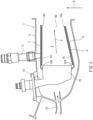
FIG. 2 is a sectional view taken along line II-II ofFIG. 1 showing thecombustor 2. As shown inFIG. 2 , adiffuser 12 is located at an upstream portion of thecasing 3 and takes the compressed air, generated by the compressor, in thecasing 3. Thefuel injectors 10 are supported by astem 13 fixed to thecasing 3. Part of the compressed air which has been taken in thecasing 3 is supplied to thefuel injectors 10 for combustion. The rest of the compressed air which has been taken in thecasing 3 cools an outer surface of theshell 6, and part of the rest of the compressed air which has been taken in the casing is supplied as cooling air into theshell 6 throughopenings 20c (seeFIG. 3 ) of theshell 6. - The tubular
outer liner 14 as a liner is located inside the tubularouter shell 7 in the radial direction R. The tubularinner liner 15 as a liner is located outside the tubularinner shell 8 in the radial direction R. Theouter liner 14 and theinner liner 15 are spaced apart from theshell 6. Theouter liner 14 and theinner liner 15 define thecombustion chamber 9. The gas which has been combusted in thecombustion chamber 9 is discharged toward the turbine through theexhaust port 9a which is defined by adownstream end 14e of theouter shell 7 in the flow direction F and adownstream end 15e of theinner shell 8 in the flow direction F. - The
outer liner 14 and theinner liner 15 are made of a ceramic matrix composite (CMC). There is a gap between theouter shell 7 and each of both ends 14d and 14e of theouter liner 14 in the flow direction F, and there is also a gap between theinner shell 8 and each of both ends 15d and 15e of theinner liner 15 in the flow direction F. InFIG. 2 , a below-describedseal wall structure 21 is not shown. - Hereinafter, since a seal wall structure of the
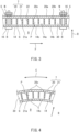
outer shell 7 and a seal wall structure of theinner shell 8 are the same in configuration as each other, theouter shell 7 will be mainly described.FIG. 3 is a partial sectional view showing thecombustor 2 ofFIG. 2 when viewed in the circumferential direction C.FIG. 4 is a partial sectional view showing thecombustor 2 ofFIG. 2 when viewed from the downstream side in the flow direction F. As shown inFIGS. 3 and 4 , theouter shell 7 includes a shellmain body 20 and theseal wall structure 21. The shellmain body 20 has a tubular shape. The shellmain body 20 includes: anouter surface 20a facing outward in the radial direction R; and aninner surface 20b facing inward in the radial direction R. - The
seal wall structure 21 projects toward theouter liner 14 from theinner surface 20b of the shellmain body 20. To be specific, theseal wall structure 21 projects inward in the radial direction R from theinner surface 20b of the shellmain body 20. The shellmain body 20 and theseal wall structure 21 may be formed as an integrated component, or theseal wall structure 21 as a separate component may be fixed (for example, joined, fastened, or the like) to the shellmain body 20. - The
outer liner 14 is attached to theouter shell 7 byfasteners 16 so as to be spaced apart from theouter shell 7 by a gap G. To be specific, there is the gap G between anouter surface 14a of theouter liner 14 and atip 21a of theseal wall structure 21, thetip 21a being located at an inside in the radial direction R. The gap G is larger than an elastically deformable amount of a spring S sandwiched between a nut N and theouter shell 7. - The
outer shell 7 is made of metal, and theouter liner 14 is made of the CMC. A coefficient of thermal expansion of theouter shell 7 and a coefficient of thermal expansion of theouter liner 14 are different from each other. Therefore, the size of the gap G may change depending on the temperature of thecombustion chamber 9 during the operation of the gas turbine 1. In the present embodiment, the gap G is set to such a size that thetip 21a of theseal wall structure 21 is maintained to be spaced apart from theouter liner 14 in an entire assumed temperature range of thecombustion chamber 9 during the operation of the gas turbine 1. - The
outer liner 14 includes: theouter surface 14a that faces outward in the radial direction R and is opposed to theouter shell 7; and aninner surface 14b that faces inward in the radial direction R and defines thecombustion chamber 9. Theouter liner 14 includescooling holes 14c that are open toward thecombustion chamber 9. A space between theouter shell 7 and theouter liner 14 is utilized as a coolingchamber 30. To be specific, theinner surface 20b of the shellmain body 20 of theouter shell 7 and theouter surface 14a of theouter liner 14 define the coolingchamber 30. - The configuration of the
fastener 16 is not especially limited. As one example, thefastener 16 includes a bolt B, the nut N, and the spring S. For example, the bolt B is attached from a side where theinner surface 14b of theouter liner 14 is located, and the nut N is attached from a side where theouter surface 20a of the shellmain body 20 of theouter shell 7 is located. The spring S is sandwiched between theouter surface 20a of the shellmain body 20 and the nut N so as to be elastically deformable. The spring S allows the displacement of theouter liner 14 relative to theouter shell 7 in the radial direction R. The spring S may be, for example, a disc spring. - The shell
main body 20 includes theopenings 20c into which the compressed air that has been taken in the casing 3 (seeFIG. 1 ) is introduced. The compressed air which has been taken in through theopenings 20c is supplied as the cooling air to the coolingchamber 30. The cooling air in the coolingchamber 30 cools theouter surface 14a of theouter liner 14. Since the cooling air in the coolingchamber 30 is the compressed air supplied from the compressor located upstream of thecombustor 2, the pressure in the coolingchamber 30 is higher than the pressure in thecombustion chamber 9. Therefore, the cooling air in the coolingchamber 30 flows out to thecombustion chamber 9 through the cooling holes 14c of theouter liner 14. The cooling air which has flowed out through the cooling holes 14c covers theinner surface 14b of theouter liner 14 to reduce the temperature increase of theinner surface 14b of theouter liner 14 which has been increased in temperature by the combustion gas of thecombustion chamber 9. - In a section of the cooling
chamber 30 when viewed in the circumferential direction C of thecombustor 2, theseal wall structure 21 includeswall portions 22 that divide the coolingchamber 30 into cavities P (seeFIG. 3 ). Theseal wall structure 21 of the present embodiment is one continuous wall as a whole. However, in a sectional view when viewed in the circumferential direction C, theseal wall structure 21 includes thewall portions 22 that are spaced apart from each other. Thewall portions 22 project from theinner surface 20b of the shellmain body 20 to theouter liner 14. A projecting end of eachwall portion 22 is thetip 21a of theseal wall structure 21. In the section of the coolingchamber 30 when viewed in the circumferential direction C of thecombustor 2, thewall portions 22 are lined up at intervals in a direction toward the end of theouter liner 14 from the cavity P that thecooling hole 14c faces among the cavities P. In a section of the coolingchamber 30 when viewed in the flow direction F of thecombustor 2, theseal wall structure 21 divides the coolingchamber 30 into the cavities P (seeFIG. 4 ). -
FIG. 5 is a partial development view showing theseal wall structure 21 ofFIG. 3 when viewed in a projecting direction of theseal wall structure 21. As shown inFIG. 5 , theseal wall structure 21 has a honeycomb shape when viewed in the projecting direction (in the present embodiment, the radial direction R) in which theseal wall structure 21 projects from the shellmain body 20. To be specific, theseal wall structure 21 includes portions extending in the circumferential direction C and portions extending in the flow direction F. When viewed in the projecting direction, each coolinghole 14c is located within any one of the cavities P. When viewed in the projecting direction, each opening 20c of the shellmain body 20 is located within any one of the cavities P. When viewed in the projecting direction, thewall portions 22 of theseal wall structure 21 are located between thecooling holes 14c. - At least one of the
openings 20c and at least one of the cooling holes 14c are opposed to the same cavity P. Specifically, at least one of theopenings 20c faces the cavity P that at least one of the cooling holes 14c faces. The cavity P that thecooling hole 14 faces and the cavity P that theopening 20c faces may be different from each other. - When the cooling air which has been introduced into the cooling
chamber 30 through theopenings 20c flows toward an end of the coolingchamber 30 in the flow direction F, the cooling air receives resistance by the existence of theseal wall structure 21. Specifically, in a region from the cavity P that thecooling hole 14c faces to bothends FIG. 2 ) of theouter liner 14 in the flow direction F, the narrow gaps G each between thetip 21a of theseal wall structure 21 and theouter surface 14a of theouter liner 14 are lined up in the flow direction F. - Therefore, the cooling air in the cavity P that the
cooling hole 14c faces hardly flows to the end of the coolingchamber 30 in the flow direction F by passage resistance of the narrow gap G. As a result, the cooling air in the coolingchamber 30 hardly leaks beyond the end of theouter liner 14, and the pressure in the coolingchamber 30 is kept adequately higher than the pressure in thecombustion chamber 9. Thus, the cooling air is appropriately discharged through thecooling holes 14c. - The
inner shell 8 also includes the seal wall structure. Since the seal wall structure of theinner shell 8 is the same as theseal wall structure 21 of theouter shell 7, a detailed explanation of the seal wall structure of theinner shell 8 is omitted. - According to the above-described configuration, the
seal wall structure 21 projects from theshell 6 made of metal, and theouter liner 14 and theinner liner 15 which are made of the CMC are prevented from becoming complex. Therefore, the coolingchamber 30 can be sealed by theseal wall structure 21 while facilitating the manufacture of theCMC liners - The
fastener 16 includes the spring S that allows the displacement of theliner 14 relative to theshell 6 in the radial direction R, and there is the gap G between thetip 21a of theseal wall structure 21 in the radial direction R and theouter surface 14a of theliner 14. Therefore, the coolingchamber 30 can be sealed by theseal wall structure 21 while allowing the displacement of theliner 14. - The gap G is set to such a size that the
tip 21a of theseal wall structure 21 is maintained to be spaced apart from theouter surface 14a of theliner 14 in an entire temperature range of thecombustion chamber 9 during the operation of the gas turbine 1. Therefore, theseal wall structure 21 does not interfere with theliner 14, and the generation of local stress applied to theliner 14 can be prevented. - In the section of the cooling
chamber 30 when viewed in the circumferential direction C of thecombustor 2, theseal wall structure 21 divides the coolingchamber 30 into the cavities P. Therefore, the cooling air in the coolingchamber 30 hardly leaks. - In the section of the cooling
chamber 30 when viewed in the circumferential direction C, thewall portions 22 are lined up at intervals in a direction toward the end of theliner 14 from the cavity P that thecooling hole 14c faces among the cavities P. Therefore, portions where the passage resistance is high are lined up, and the cooling air in the coolingchamber 30 hardly leaks. - Since the
opening 20c of theshell 7 and thecooling hole 14c of theliner 14 face the same cavity P, the cooling air can be discharged through thecooling hole 14c to thecombustion chamber 9 by adequate pressure. - In the section of the cooling
chamber 30 when viewed in the flow direction F from the upstream side to the downstream side in thecombustor 2, theseal wall structure 21 divides the coolingchamber 30 into the cavities P. Therefore, the cooling air in the coolingchamber 30 hardly leaks. - When viewed in the radial direction R, the
seal wall structure 21 includes thewall portions 22 located between thecooling holes 14c. Therefore, the pressure difference between each coolinghole 14c and thecombustion chamber 9 can be secured. - When viewed in the radial direction R, the
seal wall structure 21 has a honeycomb shape. Therefore, the seal performance of the coolingchamber 30 can be improved while increasing the strength of theshell 6. - The
seal wall structure 21 is not limited to the above configuration, and various modified examples may be adopted.FIG. 6 is a partial development view showing a first modified example of theseal wall structure 21 ofFIG. 5 when viewed in the projecting direction of theseal wall structure 21. As shown inFIG. 6 , as the first modified example, aseal structure 121 of ashell 107 may have a lattice shape when viewed in a direction in which theseal structure 121 projects from the shellmain body 20.FIG. 7 is a partial development view showing a second modified example of theseal wall structure 21 ofFIG. 5 when viewed in the projecting direction of theseal wall structure 21. As shown inFIG. 7 , as the second modified example, aseal wall structure 221 of ashell 207 may includewall portions 222 which extend in the circumferential direction C and are spaced apart from each other in the flow direction F, and may not include wall portions extending in the flow direction F. To be specific, theseal wall structure 221 may have a stripe shape when viewed in a direction in which theseal wall structure 221 projects from the shellmain body 20. Cavities P1 separated from each other by thewall portions 222 may extend continuously and entirely in the circumferential direction C. -
FIG. 8 is a partial development view showing a third modified example of theseal wall structure 21 ofFIG. 5 when viewed in the projecting direction of theseal wall structure 21. As shown inFIG. 8 , as the third modified example, aseal wall structure 321 of ashell 307 may includewall portions 322 which extend in the circumferential direction C and are located at irregular intervals in the flow direction F. To be specific, theseal wall structure 321 may have a stripe shape including irregular intervals when viewed in a direction in which theseal wall structure 321 projects from the shellmain body 20. For example, an arrangement pitch of thewall portions 322 in the flow direction F in a first region D1 corresponding to thecooling holes 14c may be set larger than that in a second region D2 located away from the first region D1 in the flow direction F. To be specific, a width of a cavity P2 in the flow direction F in the region which corresponds to thecooling holes 14c may be larger than a width of a cavity P3 in the flow direction F in the region which is located away from the cooling holes 14c in the flow direction F. Moreover, instead of the configurations shown inFIGS. 5 to 8 , the seal wall structure may have a labyrinth shape. - The foregoing has described the embodiment as an example of the technology disclosed in the present application. However, the technology in the present disclosure is not limited to this and is applicable to embodiments in which modifications, replacements, additions, omissions, and the like have been suitably made. Moreover, a new embodiment may be prepared by combining the components described in the above embodiment. For example, some of components or methods in one embodiment may be applied to another embodiment. Some components in an embodiment may be separated from the other components in the embodiment and arbitrarily extracted. Furthermore, the components shown in the attached drawings and the detailed explanations include not only components essential to solve the problems but also components for exemplifying the above technology and not essential to solve the problems.
-
- 1
- gas turbine
- 2
- combustor
- 6
- shell
- 7
- outer shell
- 8
- inner shell
- 9
- combustion chamber
- 14
- outer liner
- 14a
- outer surface
- 14b
- inner surface
- 14c
- cooling hole
- 15
- inner liner
- 16
- fastener
- 18, 19
- panel
- 20
- shell main body
- 20a
- outer surface
- 20b
- inner surface
- 20c
- opening
- 21, 121, 221, 321
- seal wall structure
- 21a tip22, 222, 322
- wall portion
- 30
- cooling chamber
- B
- bolt
- C
- circumferential direction
- G
- gap
- N
- nut
- P
- cavity
- R
- radial direction
- S
- spring
- X
- axis
Claims (10)
- A combustor of a gas turbine,
the combustor comprising:a shell including metal;a liner located inside the shell and including a ceramic matrix composite, the liner includingan inner surface defining a combustion chamber,an outer surface facing a side opposite to a side where the combustion chamber is located, andat least one cooling hole that is open toward the combustion chamber; anda cooling chamber defined between the shell and the liner, whereinthe shell includesa tubular shell main body anda seal wall structure projecting from an inner surface of the shell main body toward the liner. - The combustor according to claim 1, wherein the liner includes panels which are adjacently lined up in a circumferential direction of the combustor.
- The combustor according to claim 1 or 2, further comprising a fastener by which the liner is attached to the shell, wherein:the fastener includes a spring that allows displacement of the liner relative to the shell in a radial direction of the combustor; anda tip of the seal wall structure is spaced apart from the outer surface of the liner.
- The combustor according to claim 3, wherein the gap is set such that the tip of the seal wall structure is maintained to be spaced apart from the outer surface of the liner in an entire temperature range of the combustion chamber during operation of the gas turbine.
- The combustor according to any one of claims 1 to 4, wherein in a section of the cooling chamber when viewed in a circumferential direction of the combustor, the seal wall structure divides the cooling chamber into cavities.
- The combustor according to claim 5, wherein:the seal wall structure includes wall portions projecting from the shell main body toward the liner; andin the section of the cooling chamber when viewed in the circumferential direction of the combustor, the wall portions are lined up at intervals in a direction toward an end of the liner from the cavity that the cooling hole faces among the cavities.
- The combustor according to claim 5 or 6, wherein:the shell includes an opening into which compressed air is introduced; andthe opening and the cooling hole face one of the cavities.
- The combustor according to any one of claims 1 to 7, wherein in a section of the cooling chamber when viewed in a flow direction from an upstream side to a downstream side in the combustor, the seal wall structure divides the cooling chamber into cavities.
- The combustor according to any one of claims 1 to 8, wherein:the at least one cooling hole comprises cooling holes; andwhen viewed in a direction in which the seal wall structure projects, the seal wall structure separates the cooling holes from each other.
- The combustor according to any one of claims 1 to 9, wherein the seal wall structure has a honeycomb shape, a lattice shape, or a stripe shape when viewed in a direction in which the seal wall structure projects from the shell main body.
Applications Claiming Priority (2)
| Application Number | Priority Date | Filing Date | Title |
|---|---|---|---|
| JP2021211923A JP7854294B2 (en) | 2021-12-27 | 2021-12-27 | gas turbine combustor |
| PCT/JP2022/047574 WO2023127718A1 (en) | 2021-12-27 | 2022-12-23 | Combustor for gas turbines |
Publications (2)
| Publication Number | Publication Date |
|---|---|
| EP4459189A1 true EP4459189A1 (en) | 2024-11-06 |
| EP4459189A4 EP4459189A4 (en) | 2025-12-24 |
Family
ID=86999114
Family Applications (1)
| Application Number | Title | Priority Date | Filing Date |
|---|---|---|---|
| EP22915941.3A Pending EP4459189A4 (en) | 2021-12-27 | 2022-12-23 | Combustion chamber for gas turbines |
Country Status (4)
| Country | Link |
|---|---|
| US (1) | US12540732B2 (en) |
| EP (1) | EP4459189A4 (en) |
| JP (1) | JP7854294B2 (en) |
| WO (1) | WO2023127718A1 (en) |
Family Cites Families (32)
| Publication number | Priority date | Publication date | Assignee | Title |
|---|---|---|---|---|
| JPH0660740B2 (en) * | 1985-04-05 | 1994-08-10 | 工業技術院長 | Gas turbine combustor |
| US4642993A (en) * | 1985-04-29 | 1987-02-17 | Avco Corporation | Combustor liner wall |
| EP0224817B1 (en) * | 1985-12-02 | 1989-07-12 | Siemens Aktiengesellschaft | Heat shield arrangement, especially for the structural components of a gas turbine plant |
| US6182451B1 (en) | 1994-09-14 | 2001-02-06 | Alliedsignal Inc. | Gas turbine combustor waving ceramic combustor cans and an annular metallic combustor |
| JPH1082527A (en) * | 1996-09-05 | 1998-03-31 | Toshiba Corp | Gas turbine combustor |
| US7219498B2 (en) * | 2004-09-10 | 2007-05-22 | Honeywell International, Inc. | Waffled impingement effusion method |
| EP2267369A4 (en) | 2008-03-31 | 2014-11-26 | Kawasaki Heavy Ind Ltd | COOLING STRUCTURE FOR GAS TURBINE BURNER |
| US9127565B2 (en) | 2008-04-16 | 2015-09-08 | Siemens Energy, Inc. | Apparatus comprising a CMC-comprising body and compliant porous element preloaded within an outer metal shell |
| EP2116770B1 (en) * | 2008-05-07 | 2013-12-04 | Siemens Aktiengesellschaft | Combustor dynamic attenuation and cooling arrangement |
| US9310079B2 (en) * | 2010-12-30 | 2016-04-12 | Rolls-Royce North American Technologies, Inc. | Combustion liner with open cell foam and acoustic damping layers |
| US8727714B2 (en) * | 2011-04-27 | 2014-05-20 | Siemens Energy, Inc. | Method of forming a multi-panel outer wall of a component for use in a gas turbine engine |
| US8667682B2 (en) * | 2011-04-27 | 2014-03-11 | Siemens Energy, Inc. | Method of fabricating a nearwall nozzle impingement cooled component for an internal combustion engine |
| JP5821550B2 (en) * | 2011-11-10 | 2015-11-24 | 株式会社Ihi | Combustor liner |
| JP5927893B2 (en) * | 2011-12-15 | 2016-06-01 | 株式会社Ihi | Impinge cooling mechanism, turbine blade and combustor |
| US9335049B2 (en) * | 2012-06-07 | 2016-05-10 | United Technologies Corporation | Combustor liner with reduced cooling dilution openings |
| US9239165B2 (en) * | 2012-06-07 | 2016-01-19 | United Technologies Corporation | Combustor liner with convergent cooling channel |
| JP6066065B2 (en) | 2013-02-20 | 2017-01-25 | 三菱日立パワーシステムズ株式会社 | Gas turbine combustor with heat transfer device |
| US10422532B2 (en) * | 2013-08-01 | 2019-09-24 | United Technologies Corporation | Attachment scheme for a ceramic bulkhead panel |
| US10309652B2 (en) * | 2014-04-14 | 2019-06-04 | Siemens Energy, Inc. | Gas turbine engine combustor basket with inverted platefins |
| US9840924B2 (en) * | 2014-08-15 | 2017-12-12 | Siemens Aktiengesellschaft | Gas turbine system with a transition duct having axially extending cooling channels |
| US9534785B2 (en) * | 2014-08-26 | 2017-01-03 | Pratt & Whitney Canada Corp. | Heat shield labyrinth seal |
| EP3048370A1 (en) * | 2015-01-23 | 2016-07-27 | Siemens Aktiengesellschaft | Combustion chamber for a gas turbine engine |
| US10113745B2 (en) * | 2015-03-26 | 2018-10-30 | Ansaldo Energia Switzerland AG | Flow sleeve deflector for use in gas turbine combustor |
| US11619387B2 (en) * | 2015-07-28 | 2023-04-04 | Rolls-Royce Corporation | Liner for a combustor of a gas turbine engine with metallic corrugated member |
| EP3540314B1 (en) * | 2016-11-11 | 2023-07-12 | Kawasaki Jukogyo Kabushiki Kaisha | Combustor liner for a gas turbine |
| US20180292089A1 (en) | 2017-04-05 | 2018-10-11 | United Technologies Corporation | Combustor attachment cooling |
| US20180306120A1 (en) * | 2017-04-21 | 2018-10-25 | General Electric Company | Pressure regulated piston seal for a gas turbine combustor liner |
| EP3428535A1 (en) * | 2017-07-12 | 2019-01-16 | Siemens Aktiengesellschaft | A combustor triple liner assembly for gas turbine engines |
| KR101863779B1 (en) * | 2017-09-15 | 2018-06-01 | 두산중공업 주식회사 | Helicoidal structure for enhancing cooling performance of liner and a gas turbine combustor using the same |
| KR102050562B1 (en) * | 2017-10-30 | 2020-01-08 | 두산중공업 주식회사 | Combustor and gas turbine comprising the same |
| KR102502652B1 (en) * | 2020-10-23 | 2023-02-21 | 두산에너빌리티 주식회사 | Array impingement jet cooling structure with wavy channel |
| US11867402B2 (en) * | 2021-03-19 | 2024-01-09 | Rtx Corporation | CMC stepped combustor liner |
-
2021
- 2021-12-27 JP JP2021211923A patent/JP7854294B2/en active Active
-
2022
- 2022-12-23 EP EP22915941.3A patent/EP4459189A4/en active Pending
- 2022-12-23 WO PCT/JP2022/047574 patent/WO2023127718A1/en not_active Ceased
- 2022-12-23 US US18/724,246 patent/US12540732B2/en active Active
Also Published As
| Publication number | Publication date |
|---|---|
| US12540732B2 (en) | 2026-02-03 |
| JP2023096287A (en) | 2023-07-07 |
| US20250067433A1 (en) | 2025-02-27 |
| EP4459189A4 (en) | 2025-12-24 |
| JP7854294B2 (en) | 2026-05-01 |
| WO2023127718A1 (en) | 2023-07-06 |
Similar Documents
| Publication | Publication Date | Title |
|---|---|---|
| CA2698058C (en) | Reverse flow ceramic matrix composite combustor | |
| CA2625330C (en) | Combustor liner with improved heat shield retention | |
| EP2278125B1 (en) | Turbine nozzle assembly including radially-compliant spring member for gas turbine engine | |
| EP2325563B1 (en) | Dual walled combustor with improved liner seal | |
| EP2754962A2 (en) | Combustors with hybrid walled liners | |
| EP1172611A1 (en) | Gas turbine combustor having dome-to-line joint | |
| US9316109B2 (en) | Turbine shroud assembly and method of forming | |
| US8752395B2 (en) | Combustor liner support and seal assembly | |
| CN101713539A (en) | Impingement cooled combustor seal | |
| CN108006696A (en) | burner assembly and burner | |
| US20240053009A1 (en) | Dome-deflector for a combustor of a gas turbine | |
| US7770401B2 (en) | Combustor and component for a combustor | |
| EP4459189A1 (en) | Combustor for gas turbines | |
| US12571537B2 (en) | Combustor panel and gas turbine combustor including same | |
| EP4641087A1 (en) | Combustor for gas turbine | |
| EP4641092A1 (en) | Combustor for gas turbines |
Legal Events
| Date | Code | Title | Description |
|---|---|---|---|
| STAA | Information on the status of an ep patent application or granted ep patent |
Free format text: STATUS: THE INTERNATIONAL PUBLICATION HAS BEEN MADE |
|
| PUAI | Public reference made under article 153(3) epc to a published international application that has entered the european phase |
Free format text: ORIGINAL CODE: 0009012 |
|
| STAA | Information on the status of an ep patent application or granted ep patent |
Free format text: STATUS: REQUEST FOR EXAMINATION WAS MADE |
|
| 17P | Request for examination filed |
Effective date: 20240704 |
|
| AK | Designated contracting states |
Kind code of ref document: A1 Designated state(s): AL AT BE BG CH CY CZ DE DK EE ES FI FR GB GR HR HU IE IS IT LI LT LU LV MC ME MK MT NL NO PL PT RO RS SE SI SK SM TR |
|
| DAV | Request for validation of the european patent (deleted) | ||
| DAX | Request for extension of the european patent (deleted) | ||
| A4 | Supplementary search report drawn up and despatched |
Effective date: 20251121 |
|
| RIC1 | Information provided on ipc code assigned before grant |
Ipc: F23R 3/42 20060101AFI20251117BHEP Ipc: F01D 25/12 20060101ALI20251117BHEP Ipc: F02C 7/18 20060101ALI20251117BHEP Ipc: F02C 7/28 20060101ALI20251117BHEP Ipc: F23R 3/60 20060101ALI20251117BHEP Ipc: F23R 3/00 20060101ALI20251117BHEP |