EP4459185A1 - Burner and combustion furnace - Google Patents
Burner and combustion furnace Download PDFInfo
- Publication number
- EP4459185A1 EP4459185A1 EP22916141.9A EP22916141A EP4459185A1 EP 4459185 A1 EP4459185 A1 EP 4459185A1 EP 22916141 A EP22916141 A EP 22916141A EP 4459185 A1 EP4459185 A1 EP 4459185A1
- Authority
- EP
- European Patent Office
- Prior art keywords
- fuel
- auxiliary fuel
- nozzle
- outlet
- burner
- Prior art date
- Legal status (The legal status is an assumption and is not a legal conclusion. Google has not performed a legal analysis and makes no representation as to the accuracy of the status listed.)
- Pending
Links
Images


Classifications
-
- F—MECHANICAL ENGINEERING; LIGHTING; HEATING; WEAPONS; BLASTING
- F23—COMBUSTION APPARATUS; COMBUSTION PROCESSES
- F23D—BURNERS
- F23D17/00—Burners for combustion simultaneously or alternately of gaseous or liquid or pulverulent fuel
- F23D17/005—Burners for combustion simultaneously or alternately of gaseous or liquid or pulverulent fuel gaseous or pulverulent fuel
-
- F—MECHANICAL ENGINEERING; LIGHTING; HEATING; WEAPONS; BLASTING
- F23—COMBUSTION APPARATUS; COMBUSTION PROCESSES
- F23C—METHODS OR APPARATUS FOR COMBUSTION USING FLUID FUEL OR SOLID FUEL SUSPENDED IN A CARRIER GAS OR AIR
- F23C1/00—Combustion apparatus specially adapted for combustion of two or more kinds of fuel simultaneously or alternately, at least one kind of fuel being either a fluid fuel or a solid fuel suspended in a carrier gas or air
- F23C1/12—Combustion apparatus specially adapted for combustion of two or more kinds of fuel simultaneously or alternately, at least one kind of fuel being either a fluid fuel or a solid fuel suspended in a carrier gas or air gaseous and pulverulent fuel
-
- F—MECHANICAL ENGINEERING; LIGHTING; HEATING; WEAPONS; BLASTING
- F23—COMBUSTION APPARATUS; COMBUSTION PROCESSES
- F23D—BURNERS
- F23D1/00—Burners for combustion of pulverulent fuel
-
- F—MECHANICAL ENGINEERING; LIGHTING; HEATING; WEAPONS; BLASTING
- F23—COMBUSTION APPARATUS; COMBUSTION PROCESSES
- F23D—BURNERS
- F23D99/00—Subject matter not provided for in other groups of this subclass
- F23D99/002—Burners specially adapted for specific applications
- F23D99/004—Burners specially adapted for specific applications for use in particular heating operations
-
- F—MECHANICAL ENGINEERING; LIGHTING; HEATING; WEAPONS; BLASTING
- F23—COMBUSTION APPARATUS; COMBUSTION PROCESSES
- F23L—SUPPLYING AIR OR NON-COMBUSTIBLE LIQUIDS OR GASES TO COMBUSTION APPARATUS IN GENERAL ; VALVES OR DAMPERS SPECIALLY ADAPTED FOR CONTROLLING AIR SUPPLY OR DRAUGHT IN COMBUSTION APPARATUS; INDUCING DRAUGHT IN COMBUSTION APPARATUS; TOPS FOR CHIMNEYS OR VENTILATING SHAFTS; TERMINALS FOR FLUES
- F23L9/00—Passages or apertures for delivering secondary air for completing combustion of fuel
- F23L9/02—Passages or apertures for delivering secondary air for completing combustion of fuel by discharging the air above the fire
-
- F—MECHANICAL ENGINEERING; LIGHTING; HEATING; WEAPONS; BLASTING
- F23—COMBUSTION APPARATUS; COMBUSTION PROCESSES
- F23D—BURNERS
- F23D2204/00—Burners adapted for simultaneous or alternative combustion having more than one fuel supply
- F23D2204/20—Burners adapted for simultaneous or alternative combustion having more than one fuel supply gaseous and pulverulent fuel
-
- F—MECHANICAL ENGINEERING; LIGHTING; HEATING; WEAPONS; BLASTING
- F23—COMBUSTION APPARATUS; COMBUSTION PROCESSES
- F23D—BURNERS
- F23D2900/00—Special features of, or arrangements for burners using fluid fuels or solid fuels suspended in a carrier gas
- F23D2900/14—Special features of gas burners
- F23D2900/14021—Premixing burners with swirling or vortices creating means for fuel or air
Definitions
- the present disclosure relates to a burner that uses gas fuel as auxiliary fuel, and a combustion furnace including the burner.
- CO 2 carbon dioxide
- examples of such fuel include hydrogen (H 2 ) and ammonia (NH 3 ) as hydrogen-rich gas fuel.
- PTL 1 discloses a burner that can perform multi-fuel combustion of solid fuel and ammonia.
- the burner of PTL 1 includes: a fuel supply nozzle that discharges a fuel-air mixture containing solid fuel, such as pulverized coal, and a carrier gas for the solid fuel; an air nozzle that is located outside the fuel supply nozzle and discharges combustion air so as to separate the combustion air from the fuel-air mixture outward in a radial direction; and an ammonia supply nozzle that discharges an ammonia gas from a downstream side of an outlet of the fuel supply nozzle.
- the ammonia supply nozzle supplies the ammonia gas toward a reduction region (primary combustion region) where an oxygen concentration is low since oxygen is consumed by the combustion of the fuel at an immediately downstream side of the outlet of the fuel supply nozzle.
- the strongest high-temperature reduction region is generated in front of a portion between the outlet of the fuel supply nozzle and the outlet of the air nozzle.
- a circulating vortex is generated by the flow of the fuel-air mixture and the flows of secondary air and tertiary air located at an outer peripheral side of the fuel-air mixture. Since combustible components and heat are kept in this circulating vortex, a condition for easily causing combustion is maintained, and the circulating vortex becomes an origin of ignition.
- the high-temperature reduction region is generated in the circulating vortex and at a downstream side of the circulating vortex.
- discharging gas fuel such as ammonia toward the circulating vortex is more advantageous than discharging the ammonia toward the primary combustion region as in PTL 1.
- the flow rate of the gas fuel discharged toward the circulating vortex increases, there are concerns that: the flow of the circulating vortex is disturbed by the jet flow of the gas fuel; and the combustion reaction in the circulating vortex is suppressed since the temperature of the circulating vortex is reduced by the inflow of unreacted gas fuel.
- the present disclosure was made under these circumstances, and an object of the present disclosure is to propose the structure of a burner which uses gas fuel as auxiliary fuel and may improve combustion efficiency of the gas fuel while preventing a circulating vortex from being disturbed and preventing a combustion reaction in the circulating vortex from being deteriorated.
- a burner according to one aspect of the present disclosure includes:
- a combustion furnace according to one aspect of the present disclosure includes:
- the present disclosure can propose the structure of the burner which uses the gas fuel as the auxiliary fuel and may improve the combustion efficiency of the gas fuel while preventing the circulating vortex from being disturbed and preventing the combustion reaction in the circulating vortex from being deteriorated.
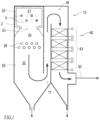
- FIG. 1 is a diagram showing the schematic configuration of the boiler 10 including the burners 5 according to one embodiment of the present disclosure.
- the boiler 10 shown in FIG. 1 includes: a combustion furnace 2 that combusts fuel; and a boiler main body 40 that generates steam by utilizing combustion heat of the fuel.
- the boiler 10 is a pulverized coal burning thermal power boiler and uses pulverized fossil fuel (solid fuel) or particulate fossil fuel (solid fuel) as main fuel.
- the boiler to which the burners 5 according to the present disclosure are applied is not limited to the pulverized coal burning boiler and may be a multi-fuel combustion boiler that uses pulverized coal and biomass as main fuel, a petroleum residuum burning boiler that uses petroleum residuum as main fuel, or the like.
- a vertical combustion chamber 20 is located in the combustion furnace 2.
- the combustion furnace 2 according to the present embodiment is an inverted vertical furnace.
- a high-temperature reduction zone 21 is located at an upper portion of the combustion chamber 20, and a low-temperature oxidation zone 22 is located at a lower portion of the combustion chamber 20.
- a throat 23 is located between the high-temperature reduction zone 21 and the low-temperature oxidation zone 22.
- the combustion furnace 2 may be a vertical furnace in which: the high-temperature reduction zone 21 is located at the lower portion of the combustion chamber 20; and the low-temperature oxidation zone 22 is located at the upper portion of the combustion chamber 20.
- the combustion furnace 2 to which the burners 5 according to the present disclosure are applied may be a combustion furnace other than the vertical furnace.
- a portion of an inner wall of the combustion furnace 2 which defines the high-temperature reduction zone 21 is covered with a fire-resistant material 25.
- the burners 5 that discharge the fuel and first-stage combustion air to the high-temperature reduction zone 21 are located on a furnace wall of an upper portion of the combustion furnace 2.
- a fuel-air mixture containing the fuel and the air is discharged from the burners 5 into the combustion chamber 20, and flame is generated.
- the burners 5 are located on a pair of opposing furnace walls. At least one burner stage in an upper-lower direction is located on each furnace wall, and each burner stage includes the burners 5 lined up in a horizontal direction.
- the burners 5 located so as to be opposed to each other as above are located in zigzag so as to be opposed to each other such that burner axes of the burners 5 do not intersect with each other.
- An outlet of the high-temperature reduction zone 21 is connected to an inlet of the low-temperature oxidation zone 22 through the throat 23.
- a smallest horizontal sectional area of the throat 23 is about 20 to 50% of a horizontal sectional area of the high-temperature reduction zone 21.
- Air nozzles 26 are located on a furnace wall of a lower portion of the combustion furnace 2. Second-stage combustion air is discharged from the air nozzles 26 to the low-temperature oxidation zone 22.
- air nozzle stages are located so as to be lined up in the upper-lower direction, and each air nozzle stage includes the air nozzles 26 lined up in the horizontal direction.
- a cooling portion 24 is located between the throat 23 and the air nozzles 26.
- the furnace wall of the cooling portion 24 is a water-cooled wall at which a water pipe (not shown) of the boiler main body 40 is located.
- An outlet 11 of the low-temperature oxidation zone 22 is connected to an inlet of a flue 28.
- a heat transfer pipe 43 of the boiler main body 40 is located at the flue 28.
- An exhaust gas processing system 30 is connected to an outlet of the flue 28.
- an air ratio of the fuel and the first-stage combustion air which are supplied to the high-temperature reduction zone 21 is maintained to be less than one (for example, about 0.7).
- a furnace internal temperature of the high-temperature reduction zone 21 surrounded by the fire-resistant material 25 hardly decreases compared to the temperature of the other furnace portion. Therefore, the atmosphere of the high-temperature reduction zone 21 is a high-temperature reduction atmosphere (atmosphere where the amount of air is smaller than the theoretical amount of air, i.e., the amount of air is inadequate) where the average temperature is about 1,500°C.
- the gasification of the fuel is promoted.
- a combustion gas is generated by the gasification of the fuel.
- the generated combustion gas flows into the low-temperature oxidation zone 22 through the throat 23.
- the air ratio in the low-temperature oxidation zone 22 is maintained to be one or more (for example, about 1.1) by the second-stage combustion air supplied from the air nozzles 26 to the low-temperature oxidation zone 22. Therefore, the atmosphere of the low-temperature oxidation zone 22 is the oxidizing atmosphere, and thus, the combustion of the combustion gas is promoted in the low-temperature oxidation zone 22.
- the combustion of an unburned portion of the combustion gas is completed.
- a flue gas from the low-temperature oxidation zone 22 flows out to the exhaust gas processing system 30 through the flue 28.
- the heat of the flue gas is recovered by the heat transfer pipe 43 located at the flue 28 and the furnace wall, and the steam is generated by the boiler main body 40.
- the generated steam is utilized by, for example, a steam turbine of a power generation facility.
- the burner 5 included in the boiler 10 configured as above is a multi-fuel combustion burner that uses the solid fuel as the main fuel and utilizes hydrogen-containing gas fuel as auxiliary fuel.
- the solid fuel is, for example, pulverized fossil fuel or particulate fossil fuel, such as pulverized coal.
- an ammonia gas containing hydrogen and nitrogen is adopted as the gas fuel.
- a hydrogen gas or a by-product gas generated at a plant may be used as the gas fuel.
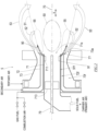
- FIG. 2 is a schematic sectional view of the burner 5 according to the present disclosure.
- FIG. 3 is an enlarged view showing an outlet of the burner 5 of FIG. 2 and its vicinity.
- the burner 5 includes a multiple nozzle including a first nozzle 71, a second nozzle 72, and a third nozzle 73 which are located coaxially about a predetermined burner axis 70.
- a direction in which the burner axis 70 extends is referred to as a "burner axis direction X.”
- the first nozzle 71 is supplied with powdered solid fuel and carrier air that carries the solid fuel.
- the carrier air is primary air (primary combustion air).
- a first flame holding plate 77 that is continuous in a circumferential direction is located at a downstream end of the first nozzle 71.
- the first flame holding plate 77 increases in diameter toward the downstream end of the first nozzle 71 in a trumpet shape.
- a main fuel outlet 71a is defined by the first flame holding plate 77 at the downstream end of the first nozzle 71.
- a fuel-air mixture 51 containing the solid fuel and the carrier air is discharged from the main fuel outlet 71a.
- a swirling adjustment plate 711 is located inside the downstream end of the first nozzle 71 and upstream of the first flame holding plate 77.
- a dispersion blade 713 is located inside the first nozzle 71 and upstream of the swirling adjustment plate 711.
- a heavy oil burner 79 through which the burner axis 70 extends is inserted into a center axis portion of the first nozzle 71.
- a downstream end of the heavy oil burner 79 is located in the vicinity of the downstream end of the first nozzle 71. Therefore, a passage section of the downstream end of the first nozzle 71 has an annular shape about the burner axis 70.
- the second nozzle 72 is located at an outer peripheral side of the first nozzle 71.
- a second passage 72f having an annular passage section is defined between the first nozzle 71 and the second nozzle 72.
- the second passage 72f is supplied with secondary air 52 (secondary combustion air) from a wind box.
- a secondary air outlet 72a that is a downstream end of the second passage 72f is located at an outer peripheral side of the main fuel outlet 71a and emits the secondary air 52 to an outer peripheral side of the flow of the fuel-air mixture 51 discharged from the main fuel outlet 71a.
- the third nozzle 73 is located at an outer peripheral side of the second nozzle 72.
- a third passage 73f having an annular passage section is defined between the third nozzle 73 and the second nozzle 72.
- the third passage 73f is supplied with tertiary air 53 (tertiary combustion air) from a wind box.
- a tertiary air outlet 73a that is a downstream end of the third passage 73f is located at an outer peripheral side of the secondary air outlet 72a and emits the tertiary air 53 at an outer peripheral side of the secondary air 52 discharged from the secondary air outlet 72a.
- a second flame holding plate 72b that increases in diameter toward the downstream side in a trumpet shape is located at a downstream end of the second nozzle 72.
- an outer guide 73b that increases in diameter toward the downstream side in a trumpet shape is located at an opening edge of a downstream end of the third nozzle 73.
- the secondary air 52 discharged from the secondary air outlet 72a is guided by the first flame holding plate 77 and the second flame holding plate 72b so as to flow away from the fuel-air mixture 51 discharged from the first nozzle 71, i.e., flow outward.
- the tertiary air 53 discharged from the third nozzle 73 is guided by the second flame holding plate 72b and the outer guide 73b so as to flow away from the secondary air 52 discharged from the second nozzle 72, i.e., flow outward.
- FIG. 4 is a diagram showing the outlet of the burner 5 when viewed from a front side in the burner axis direction X.
- auxiliary fuel injection nozzles 91 are located on an outer surface of the first nozzle 71 so as to be lined up in the circumferential direction.
- the diameter of each auxiliary fuel injection nozzle 91 is adequately smaller than the diameter of the first nozzle 71.
- Each auxiliary fuel injection nozzle 91 extends in the burner axis direction X along the outer surface of the first nozzle 71. It is desirable that the auxiliary fuel injection nozzles 91 extend on the outer surface of the first nozzle 71 so as not to obstruct the flow of the secondary air 52 in the second passage 72f.
- each auxiliary fuel injection nozzle 91 is joined to the outer surface of the first nozzle 71, and therefore, the auxiliary fuel injection nozzles 91 and the first nozzle 71 are integrated with each other.
- the first nozzle 71 and the auxiliary fuel injection nozzles 91 may be chemically joined to each other by welding or may be mechanically joined to each other by, for example, bolts.
- First passages 91f in the auxiliary fuel injection nozzles 91 are supplied with gas fuel 90 from a gas fuel source.
- the gas fuel 90 is discharged from auxiliary fuel outlets 91a that are downstream ends of the auxiliary fuel injection nozzles 91.
- the first passages 91f may be supplied with combustion air in addition to the gas fuel 90.
- a gas discharged from the auxiliary fuel outlets 91a may be switchable among the gas fuel 90, the combustion air, and a fuel-air mixture containing the gas fuel 90 and the combustion air.
- the auxiliary fuel outlets 91a are located between the main fuel outlet 71a and the secondary air outlet 72a.
- the auxiliary fuel outlets 91a are lined up in the circumferential direction along an outer peripheral edge of the first flame holding plate 77 located at the downstream end of the first nozzle 71. It is desirable that the auxiliary fuel outlets 91a be lined up uniformly in the circumferential direction.
- the auxiliary fuel injection nozzles 91 are in contact with the outer peripheral edge of the first flame holding plate 77, and the auxiliary fuel outlets 91a are located along the outer peripheral edge of the first flame holding plate 77 at a slightly outside of the outer peripheral edge of the first flame holding plate 77.
- the fuel-air mixture 51 containing the solid fuel and the primary air which have been supplied to the first nozzle 71 is discharged as swirling flow from the main fuel outlet 71a by the actions of the dispersion blade 713 and the swirling adjustment plate 711.
- the secondary air 52 is emitted from the secondary air outlet 72a
- the tertiary air 53 is emitted from the tertiary air outlet 73a.
- the secondary air 52 is emitted so as to spread outward in a radial direction about the burner axis 70 by the actions of the first flame holding plate 77 and the second flame holding plate 72b.
- the tertiary air 53 is emitted so as to spread outward in the radial direction by the actions of the second flame holding plate 72b and the outer guide 73b.
- a circulating vortex 55 is generated at a boundary between the flow of the fuel-air mixture 51 and the flow of the secondary air 52 by a pressure decrease.
- a high-temperature combustion gas stays in the circulating vortex 55.
- an outer circulating vortex 55a and an inner circulating vortex 55b located closer to the burner axis 70 than the outer circulating vortex 55a are generated.
- Each of the outer circulating vortex 55a and the inner circulating vortex 55b includes: forward flow flowing toward the downstream side; and reverse flow returning to the upstream side.
- a circulating region 50 is generated at a radially inner side of the circulating vortex 55 by the swirling of the tertiary air 53.
- the circulating region 50 In the circulating region 50, circulating flow by which discharging flow of the fuel-air mixture 51 from the main fuel outlet 71a is made to return to the main fuel outlet 71a is generated, and the high-temperature combustion gas and the unburned circulating gas are exchanged with each other at all times.
- volatile components of the solid fuel in the fuel-air mixture 51 are quickly combusted, and outer periphery ignited flame is generated in the circulating vortex 55.
- the combustion air and the fuel-air mixture 51 are mixed with each other sequentially in order of the secondary air 52 and the tertiary air 53, and this generates the combustion.
- the burner 5 is switchable among single-fuel combustion of the solid fuel, single-fuel combustion of the gas fuel, and multi-fuel combustion of the solid fuel and the gas fuel.
- the combustion air is supplied to the first passages 91f, or the supply of the gas fuel to the first passages 91f is stopped.
- the combustion air is supplied to the first nozzle 71, and the gas fuel is supplied to the first passages 91f.
- the solid fuel and the combustion air are supplied to the first nozzle 71, and the gas fuel 90 is supplied to the first passages 91f.
- the burner 5 can switch the single-fuel combustion and the multi-fuel combustion without stopping the operation of the boiler 10.
- the flow of the gas fuel 90 emitted from the auxiliary fuel outlets 91a joins outermost flow of the circulating vortex 55, i.e., the forward flow flowing toward the downstream side.
- the gas fuel 90 is taken in the circulating vortex 55 that is the origin of the ignition.
- the gas fuel 90 can be efficiently combusted.
- FIG. 5 is a diagram showing the outlet of a burner 5A according to Modified Example 1 when viewed from the front side in the burner axis direction X.
- the arrangement of the auxiliary fuel outlets 91a of the auxiliary fuel injection nozzles 91 in the burner 5A according to Modified Example 1 shown in FIG. 5 is different from that in the burner 5 according to the above embodiment.
- cutouts are located at the outer peripheral edge of the first flame holding plate 77, and the downstream ends of the auxiliary fuel injection nozzles 91 extend through the cutouts.
- a section of each cutout may have such a shape that part of the auxiliary fuel injection nozzle 91 or the entire auxiliary fuel injection nozzle 91 is fitted in the cutout.
- each auxiliary fuel outlet 91a is located inside the outer peripheral edge of the first flame holding plate 77, and the rest of each auxiliary fuel outlet 91a is located outside the outer peripheral edge of the first flame holding plate 77.
- unevenness at the outer peripheral edge of the first flame holding plate 77 is reduced.
- the auxiliary fuel outlets 91a can be prevented from influencing the flow of the secondary air 52 emitted from the secondary air outlet 72a and the flow of the fuel-air mixture 51 emitted from the main fuel outlet 71a.
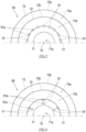
- FIG. 6 is a diagram showing the outlet of a burner 5B according to Modified Example 2 when viewed from the front side in the burner axis direction X.
- inner auxiliary fuel outlets 91a and outer auxiliary fuel outlets 91a are located such that the corresponding inner and outer auxiliary fuel outlets 91a are at the same rotational position about the burner axis 70.
- the inner and outer auxiliary fuel outlets 91a are located inside the outer peripheral edge of the first flame holding plate 77 and outside an inner peripheral edge of the first flame holding plate 77.
- the downstream ends of the auxiliary fuel injection nozzles 91 penetrate the first flame holding plate 77.
- fan-shaped cutouts 77a may be located at the outer peripheral edge of the first flame holding plate 77, and the downstream ends of the auxiliary fuel injection nozzles 91 may extend through the cutouts 77a.
- FIG. 8 is an enlarged sectional view showing the outlet of the burner 5B according to Modified Example 2.
- the flow of the gas fuel 90 discharged from the inner auxiliary fuel outlets 91a joins forward flow of the inner circulating vortex 55b, the forward flow flowing toward the downstream side.
- the positions and directions of the inner auxiliary fuel outlets 91a are adjusted such that the flow of the gas fuel 90 discharged from the inner auxiliary fuel outlets 91a joins the forward flow of the inner circulating vortex 55b, the forward flow flowing toward the downstream side.
- the flow of the gas fuel 90 discharged from the outer auxiliary fuel outlets 91a joins forward flow of the outer circulating vortex 55a, the forward flow flowing toward the downstream side.
- the positions and directions of the outer auxiliary fuel outlets 91a are adjusted such that the flow of the gas fuel 90 discharged from the outer auxiliary fuel outlets 91a joins the forward flow of the outer circulating vortex 55a, the forward flow flowing toward the downstream side.
- the gas fuel 90 is supplied to the outer circulating vortex 55a and the inner circulating vortex 55b.
- a multi-fuel combustion ratio of the gas fuel 90 can be improved while suppressing a discharging flow velocity of the gas fuel 90 discharged from each auxiliary fuel outlet 91a.
- the burner 5, 5A, or 5B according to the present disclosure includes:
- the auxiliary fuel injection nozzles 91 include: the auxiliary fuel outlets 91a lined up along the outer peripheral edge of the flame holding plate 77; or the auxiliary fuel outlets 91a located inside the outer peripheral edge of the flame holding plate 77 and outside the inner peripheral edge of the flame holding plate 77.
- the auxiliary fuel outlets 91a discharge the gas fuel 90 as the auxiliary fuel toward a boundary between the flow of the fuel-air mixture 51 discharged from the main fuel outlet 71a and the flow of the secondary air 52 discharged from the secondary air outlet 72a.
- the gas fuel 90 discharged from the auxiliary fuel outlets 91a flows toward the circulating vortex 55 generated at the boundary between the flow of the fuel-air mixture 51 and the flow of the secondary air 52.
- the gas fuel 90 is taken in the circulating vortex 55 that is the origin of the ignition, and therefore, the gas fuel 90 can be efficiently combusted.
- the gas fuel 90 is dispersedly discharged from the auxiliary fuel outlets 91a. Therefore, as compared to a case where the number of auxiliary fuel outlets 91a is one, an injection flow velocity for supplying the same amount of gas fuel 90 can be made low.
- the number of auxiliary fuel outlets 91a may be at least two, but is desirably large.
- the auxiliary fuel injection nozzles 91 may be joined to the outer surface of the first nozzle 71.
- the auxiliary fuel injection nozzles 91 and the first nozzle 71 can be handled integrally. Moreover, since the auxiliary fuel injection nozzles 91 extend along the outer surface of the first nozzle 71, the auxiliary fuel injection nozzles 91 can be prevented from influencing the flow field of the secondary air 52 in the second passage 72f.
- the downstream ends of the auxiliary fuel injection nozzles 91 may extend through the flame holding plate 77.
- the auxiliary fuel outlets 91a can be located inside the outer peripheral edge of the flame holding plate 77.
- the flame holding plate 77 may include cutouts at an outer peripheral edge thereof, and the downstream ends of the auxiliary fuel injection nozzles 91 extend through the cutouts.
- the auxiliary fuel outlets 91a can be located inside the outer peripheral edge of the flame holding plate 77. Moreover, the unevenness at the outer peripheral edge of the flame holding plate 77 can be reduced.
- the auxiliary fuel outlets 91a may discharge the gas fuel 90 to the forward flow of the circulating vortex 55 generated at the boundary between the flow of the fuel-air mixture 51 and the flow of the secondary air 52, the forward flow flowing toward the downstream side.
- the gas fuel 90 When the gas fuel 90 is emitted so as to contact the reverse flow of the circulating vortex 55 which flows toward the upstream side, the circulating vortex 55 may be disturbed by the flow of the gas fuel 90.
- the gas fuel 90 is discharged to the forward flow of the circulating vortex 55, the forward flow flowing toward the downstream side. Therefore, the gas fuel 90 is taken in the circulating vortex 55 without disturbing the flow of the circulating vortex 55.
- the circulating vortex 55 may include the outer circulating vortex 55a and the inner circulating vortex 55b located closer to the burner axis 70 than the outer circulating vortex 55a.
- the auxiliary fuel outlets 91a may include the inner auxiliary fuel outlet 91a and the outer auxiliary fuel outlet 91a which are at a substantially same rotational position about the burner axis 70.
- the inner auxiliary fuel outlet 91a may discharge the gas fuel 90 toward the forward flow of the inner circulating vortex 55b, the forward flow flowing toward the downstream side.
- the outer auxiliary fuel outlet 91a may discharge the gas fuel 90 toward the forward flow of the outer circulating vortex 55a, the forward flow flowing toward the downstream side.
- the gas fuel 90 discharged from the auxiliary fuel outlets 91a is dispersedly supplied to the outer circulating vortex 55a and the inner circulating vortex 55b. Therefore, the discharging flow velocity of the gas fuel 90 flowing toward the circulating vortex 55 can be suppressed. Then, it is possible to prevent a case where the circulating vortex 55 is disturbed by the discharged gas fuel 90 and a case where the combustion reaction in the circulating vortex 55 is deteriorated by the temperature decrease of the circulating vortex 55.
- the gas fuel outlets 91a may be switchable so as to emit the combustion air instead of the gas fuel 90.
- each of the burners 5, 5A, and 5B configured as above is switchable between the combustion of only the main fuel and the combustion of the main fuel and the auxiliary fuel.
- the solid fuel is used as the main fuel.
- the main fuel may be gas fuel or liquid fuel.
- the main fuel and the auxiliary fuel may be the same type of fuel.
- the gas fuel 90 may be an ammonia gas.
- the combustion furnace 2 includes: the high-temperature reduction zone 21 which has a reduction atmosphere and at which at least one burner 5, 5A, or 5B is located; and the low-temperature oxidation zone 22 which has an oxidizing atmosphere and is lower in temperature than the high-temperature reduction zone 21 and into which the combustion gas generated in the high-temperature reduction zone 21 flows.
- the multi-fuel combustion of the solid fuel and the gas fuel containing a large amount of nitrogen is performed in the high-temperature reduction zone 21.
- in-furnace NOx removal of NOx generated from the solid fuel and the nitrogen contained in the gas fuel is performed, and therefore, the discharge of the NOx can be suppressed.
- a water gas shift reaction in which water generated from the solid fuel and/or the hydrogen contained in the gas fuel is converted into an activated gas is caused.
- the combustion efficiency can be improved.
- the gas fuel is the ammonia gas, a large amount of water which is subjected to the water gas shift reaction is generated. Therefore, the combustion efficiency can be further improved.
Landscapes
- Engineering & Computer Science (AREA)
- Chemical & Material Sciences (AREA)
- Combustion & Propulsion (AREA)
- Mechanical Engineering (AREA)
- General Engineering & Computer Science (AREA)
- Combustion Of Fluid Fuel (AREA)
- Pre-Mixing And Non-Premixing Gas Burner (AREA)
Abstract
Description
- The present disclosure relates to a burner that uses gas fuel as auxiliary fuel, and a combustion furnace including the burner.
- According to the current trend regarding the reduction of carbon dioxide (CO2), the use of CO2-free fuel which does not generate carbon dioxide in a thermal power boiler is required. Examples of such fuel include hydrogen (H2) and ammonia (NH3) as hydrogen-rich gas fuel. For example, PTL 1 discloses a burner that can perform multi-fuel combustion of solid fuel and ammonia.
- The burner of PTL 1 includes: a fuel supply nozzle that discharges a fuel-air mixture containing solid fuel, such as pulverized coal, and a carrier gas for the solid fuel; an air nozzle that is located outside the fuel supply nozzle and discharges combustion air so as to separate the combustion air from the fuel-air mixture outward in a radial direction; and an ammonia supply nozzle that discharges an ammonia gas from a downstream side of an outlet of the fuel supply nozzle. The ammonia supply nozzle supplies the ammonia gas toward a reduction region (primary combustion region) where an oxygen concentration is low since oxygen is consumed by the combustion of the fuel at an immediately downstream side of the outlet of the fuel supply nozzle.
- PTL 1:
Japanese Laid-Open Patent Application Publication No. 2019-203631 - According to the structure of the burner disclosed in PTL 1, the strongest high-temperature reduction region is generated in front of a portion between the outlet of the fuel supply nozzle and the outlet of the air nozzle. At this position, a circulating vortex is generated by the flow of the fuel-air mixture and the flows of secondary air and tertiary air located at an outer peripheral side of the fuel-air mixture. Since combustible components and heat are kept in this circulating vortex, a condition for easily causing combustion is maintained, and the circulating vortex becomes an origin of ignition. In addition, the high-temperature reduction region is generated in the circulating vortex and at a downstream side of the circulating vortex. Therefore, it is thought that from the viewpoint of the improvement of combustion efficiency, discharging gas fuel such as ammonia toward the circulating vortex is more advantageous than discharging the ammonia toward the primary combustion region as in PTL 1. On the other hand, when the flow rate of the gas fuel discharged toward the circulating vortex increases, there are concerns that: the flow of the circulating vortex is disturbed by the jet flow of the gas fuel; and the combustion reaction in the circulating vortex is suppressed since the temperature of the circulating vortex is reduced by the inflow of unreacted gas fuel.
- The present disclosure was made under these circumstances, and an object of the present disclosure is to propose the structure of a burner which uses gas fuel as auxiliary fuel and may improve combustion efficiency of the gas fuel while preventing a circulating vortex from being disturbed and preventing a combustion reaction in the circulating vortex from being deteriorated.
- In order to solve the above problems, a burner according to one aspect of the present disclosure includes:
- a first nozzle having a tubular shape about a burner axis and including
- a main fuel outlet that discharges a fuel-air mixture containing main fuel and primary combustion air and
- a flame holding plate located around the main fuel outlet;
- a second nozzle located coaxially with the first nozzle and including a secondary air outlet that emits secondary combustion air at an outer peripheral side of the main fuel outlet; and
- auxiliary fuel injection nozzles extending along an outer surface of the first nozzle in parallel with the burner axis, wherein:
- the auxiliary fuel injection nozzles include
- auxiliary fuel outlets lined up along an outer peripheral edge of the flame holding plate or
- auxiliary fuel outlets located inside the outer peripheral edge of the flame holding plate and outside an inner peripheral edge of the flame holding plate: and
- the auxiliary fuel outlets discharge gas fuel as auxiliary fuel toward a boundary between flow of the fuel-air mixture discharged from the main fuel outlet and flow of the secondary combustion air discharged from the secondary air outlet.
- the auxiliary fuel injection nozzles include
- Moreover, a combustion furnace according to one aspect of the present disclosure includes:
- a high-temperature reduction zone which has a reduction atmosphere and at which at least one burner described above is located; and
- a low-temperature oxidation zone which has an oxidizing atmosphere and is lower in temperature than the high-temperature reduction zone and into which a combustion gas generated in the high-temperature reduction zone flows.
- The present disclosure can propose the structure of the burner which uses the gas fuel as the auxiliary fuel and may improve the combustion efficiency of the gas fuel while preventing the circulating vortex from being disturbed and preventing the combustion reaction in the circulating vortex from being deteriorated.
-
-
FIG. 1 is a diagram showing a schematic configuration of a boiler including burners according to one embodiment of the present disclosure. -
FIG. 2 is a schematic sectional view of the burner according to the present disclosure. -
FIG. 3 is an enlarged sectional view showing an outlet of the burner shown inFIG. 2 . -
FIG. 4 is a diagram showing the outlet of the burner when viewed from a front side in a burner axis direction. -
FIG. 5 is a diagram showing the outlet of the burner according to Modified Example 1 when viewed from the front side in the burner axis direction. -
FIG. 6 is a diagram showing the outlet of the burner according to Modified Example 2 when viewed from the front side in the burner axis direction. -
FIG. 7 is a diagram showing the outlet of the burner according to Modified Example 2 when viewed from the front side in the burner axis direction. -
FIG. 8 is an enlarged sectional view showing the outlet of the burner according to Modified Example 2. - Hereinafter, an embodiment of the present disclosure will be described with reference to the drawings. First, the schematic configuration of a
boiler 10 includingburners 5 according to one embodiment of the present disclosure will be described. -
FIG. 1 is a diagram showing the schematic configuration of theboiler 10 including theburners 5 according to one embodiment of the present disclosure. Theboiler 10 shown inFIG. 1 includes: acombustion furnace 2 that combusts fuel; and a boilermain body 40 that generates steam by utilizing combustion heat of the fuel. Theboiler 10 is a pulverized coal burning thermal power boiler and uses pulverized fossil fuel (solid fuel) or particulate fossil fuel (solid fuel) as main fuel. However, the boiler to which theburners 5 according to the present disclosure are applied is not limited to the pulverized coal burning boiler and may be a multi-fuel combustion boiler that uses pulverized coal and biomass as main fuel, a petroleum residuum burning boiler that uses petroleum residuum as main fuel, or the like. - A
vertical combustion chamber 20 is located in thecombustion furnace 2. Thecombustion furnace 2 according to the present embodiment is an inverted vertical furnace. A high-temperature reduction zone 21 is located at an upper portion of thecombustion chamber 20, and a low-temperature oxidation zone 22 is located at a lower portion of thecombustion chamber 20. Athroat 23 is located between the high-temperature reduction zone 21 and the low-temperature oxidation zone 22. However, thecombustion furnace 2 may be a vertical furnace in which: the high-temperature reduction zone 21 is located at the lower portion of thecombustion chamber 20; and the low-temperature oxidation zone 22 is located at the upper portion of thecombustion chamber 20. Or, the combustion furnace 2 to which theburners 5 according to the present disclosure are applied may be a combustion furnace other than the vertical furnace. - A portion of an inner wall of the
combustion furnace 2 which defines the high-temperature reduction zone 21 is covered with a fire-resistant material 25. Theburners 5 that discharge the fuel and first-stage combustion air to the high-temperature reduction zone 21 are located on a furnace wall of an upper portion of thecombustion furnace 2. A fuel-air mixture containing the fuel and the air is discharged from theburners 5 into thecombustion chamber 20, and flame is generated. Theburners 5 are located on a pair of opposing furnace walls. At least one burner stage in an upper-lower direction is located on each furnace wall, and each burner stage includes theburners 5 lined up in a horizontal direction. Theburners 5 located so as to be opposed to each other as above are located in zigzag so as to be opposed to each other such that burner axes of theburners 5 do not intersect with each other. - An outlet of the high-
temperature reduction zone 21 is connected to an inlet of the low-temperature oxidation zone 22 through thethroat 23. A smallest horizontal sectional area of thethroat 23 is about 20 to 50% of a horizontal sectional area of the high-temperature reduction zone 21. -
Air nozzles 26 are located on a furnace wall of a lower portion of thecombustion furnace 2. Second-stage combustion air is discharged from theair nozzles 26 to the low-temperature oxidation zone 22. In the present embodiment, air nozzle stages are located so as to be lined up in the upper-lower direction, and each air nozzle stage includes theair nozzles 26 lined up in the horizontal direction. In the low-temperature oxidation zone 22, a coolingportion 24 is located between thethroat 23 and theair nozzles 26. The furnace wall of the coolingportion 24 is a water-cooled wall at which a water pipe (not shown) of the boilermain body 40 is located. - An
outlet 11 of the low-temperature oxidation zone 22 is connected to an inlet of aflue 28. Aheat transfer pipe 43 of the boilermain body 40 is located at theflue 28. An exhaustgas processing system 30 is connected to an outlet of theflue 28. - In the
boiler 10 configured as above, an air ratio of the fuel and the first-stage combustion air which are supplied to the high-temperature reduction zone 21 is maintained to be less than one (for example, about 0.7). In addition, a furnace internal temperature of the high-temperature reduction zone 21 surrounded by the fire-resistant material 25 hardly decreases compared to the temperature of the other furnace portion. Therefore, the atmosphere of the high-temperature reduction zone 21 is a high-temperature reduction atmosphere (atmosphere where the amount of air is smaller than the theoretical amount of air, i.e., the amount of air is inadequate) where the average temperature is about 1,500°C. In the high-temperature reduction zone 21, the gasification of the fuel is promoted. - In the high-
temperature reduction zone 21, a combustion gas is generated by the gasification of the fuel. The generated combustion gas flows into the low-temperature oxidation zone 22 through thethroat 23. The air ratio in the low-temperature oxidation zone 22 is maintained to be one or more (for example, about 1.1) by the second-stage combustion air supplied from theair nozzles 26 to the low-temperature oxidation zone 22. Therefore, the atmosphere of the low-temperature oxidation zone 22 is the oxidizing atmosphere, and thus, the combustion of the combustion gas is promoted in the low-temperature oxidation zone 22. - In the low-
temperature oxidation zone 22, the combustion of an unburned portion of the combustion gas is completed. A flue gas from the low-temperature oxidation zone 22 flows out to the exhaustgas processing system 30 through theflue 28. The heat of the flue gas is recovered by theheat transfer pipe 43 located at theflue 28 and the furnace wall, and the steam is generated by the boilermain body 40. The generated steam is utilized by, for example, a steam turbine of a power generation facility. - The
burner 5 included in theboiler 10 configured as above is a multi-fuel combustion burner that uses the solid fuel as the main fuel and utilizes hydrogen-containing gas fuel as auxiliary fuel. The solid fuel is, for example, pulverized fossil fuel or particulate fossil fuel, such as pulverized coal. In the present embodiment, an ammonia gas containing hydrogen and nitrogen is adopted as the gas fuel. However, a hydrogen gas or a by-product gas generated at a plant may be used as the gas fuel. -
FIG. 2 is a schematic sectional view of theburner 5 according to the present disclosure.FIG. 3 is an enlarged view showing an outlet of theburner 5 ofFIG. 2 and its vicinity. As shown inFIGS. 2 and3 , theburner 5 includes a multiple nozzle including afirst nozzle 71, asecond nozzle 72, and athird nozzle 73 which are located coaxially about apredetermined burner axis 70. A direction in which theburner axis 70 extends is referred to as a "burner axis direction X." - The
first nozzle 71 is supplied with powdered solid fuel and carrier air that carries the solid fuel. The carrier air is primary air (primary combustion air). A firstflame holding plate 77 that is continuous in a circumferential direction is located at a downstream end of thefirst nozzle 71. The firstflame holding plate 77 increases in diameter toward the downstream end of thefirst nozzle 71 in a trumpet shape. Amain fuel outlet 71a is defined by the firstflame holding plate 77 at the downstream end of thefirst nozzle 71. A fuel-air mixture 51 containing the solid fuel and the carrier air is discharged from themain fuel outlet 71a. - A swirling
adjustment plate 711 is located inside the downstream end of thefirst nozzle 71 and upstream of the firstflame holding plate 77. Adispersion blade 713 is located inside thefirst nozzle 71 and upstream of the swirlingadjustment plate 711. - A
heavy oil burner 79 through which theburner axis 70 extends is inserted into a center axis portion of thefirst nozzle 71. A downstream end of theheavy oil burner 79 is located in the vicinity of the downstream end of thefirst nozzle 71. Therefore, a passage section of the downstream end of thefirst nozzle 71 has an annular shape about theburner axis 70. - The
second nozzle 72 is located at an outer peripheral side of thefirst nozzle 71. Asecond passage 72f having an annular passage section is defined between thefirst nozzle 71 and thesecond nozzle 72. Thesecond passage 72f is supplied with secondary air 52 (secondary combustion air) from a wind box. Asecondary air outlet 72a that is a downstream end of thesecond passage 72f is located at an outer peripheral side of themain fuel outlet 71a and emits thesecondary air 52 to an outer peripheral side of the flow of the fuel-air mixture 51 discharged from themain fuel outlet 71a. - The
third nozzle 73 is located at an outer peripheral side of thesecond nozzle 72. Athird passage 73f having an annular passage section is defined between thethird nozzle 73 and thesecond nozzle 72. Thethird passage 73f is supplied with tertiary air 53 (tertiary combustion air) from a wind box. Atertiary air outlet 73a that is a downstream end of thethird passage 73f is located at an outer peripheral side of thesecondary air outlet 72a and emits thetertiary air 53 at an outer peripheral side of thesecondary air 52 discharged from thesecondary air outlet 72a. - A second
flame holding plate 72b that increases in diameter toward the downstream side in a trumpet shape is located at a downstream end of thesecond nozzle 72. Moreover, anouter guide 73b that increases in diameter toward the downstream side in a trumpet shape is located at an opening edge of a downstream end of thethird nozzle 73. Thesecondary air 52 discharged from thesecondary air outlet 72a is guided by the firstflame holding plate 77 and the secondflame holding plate 72b so as to flow away from the fuel-air mixture 51 discharged from thefirst nozzle 71, i.e., flow outward. Moreover, thetertiary air 53 discharged from thethird nozzle 73 is guided by the secondflame holding plate 72b and theouter guide 73b so as to flow away from thesecondary air 52 discharged from thesecond nozzle 72, i.e., flow outward. -
FIG. 4 is a diagram showing the outlet of theburner 5 when viewed from a front side in the burner axis direction X. As shown inFIGS. 2 ,3, and 4 , auxiliaryfuel injection nozzles 91 are located on an outer surface of thefirst nozzle 71 so as to be lined up in the circumferential direction. The diameter of each auxiliaryfuel injection nozzle 91 is adequately smaller than the diameter of thefirst nozzle 71. Each auxiliaryfuel injection nozzle 91 extends in the burner axis direction X along the outer surface of thefirst nozzle 71. It is desirable that the auxiliaryfuel injection nozzles 91 extend on the outer surface of thefirst nozzle 71 so as not to obstruct the flow of thesecondary air 52 in thesecond passage 72f. In the present embodiment, each auxiliaryfuel injection nozzle 91 is joined to the outer surface of thefirst nozzle 71, and therefore, the auxiliaryfuel injection nozzles 91 and thefirst nozzle 71 are integrated with each other. Thefirst nozzle 71 and the auxiliaryfuel injection nozzles 91 may be chemically joined to each other by welding or may be mechanically joined to each other by, for example, bolts. -
First passages 91f in the auxiliaryfuel injection nozzles 91 are supplied withgas fuel 90 from a gas fuel source. Thegas fuel 90 is discharged fromauxiliary fuel outlets 91a that are downstream ends of the auxiliaryfuel injection nozzles 91. Moreover, thefirst passages 91f may be supplied with combustion air in addition to thegas fuel 90. In this case, a gas discharged from theauxiliary fuel outlets 91a may be switchable among thegas fuel 90, the combustion air, and a fuel-air mixture containing thegas fuel 90 and the combustion air. - The
auxiliary fuel outlets 91a are located between themain fuel outlet 71a and thesecondary air outlet 72a. Theauxiliary fuel outlets 91a are lined up in the circumferential direction along an outer peripheral edge of the firstflame holding plate 77 located at the downstream end of thefirst nozzle 71. It is desirable that theauxiliary fuel outlets 91a be lined up uniformly in the circumferential direction. In the example shown inFIG. 4 , the auxiliaryfuel injection nozzles 91 are in contact with the outer peripheral edge of the firstflame holding plate 77, and theauxiliary fuel outlets 91a are located along the outer peripheral edge of the firstflame holding plate 77 at a slightly outside of the outer peripheral edge of the firstflame holding plate 77. - In the
burner 5 configured as above, the fuel-air mixture 51 containing the solid fuel and the primary air which have been supplied to thefirst nozzle 71 is discharged as swirling flow from themain fuel outlet 71a by the actions of thedispersion blade 713 and the swirlingadjustment plate 711. Moreover, at an outer peripheral side of themain fuel outlet 71a, thesecondary air 52 is emitted from thesecondary air outlet 72a, and thetertiary air 53 is emitted from thetertiary air outlet 73a. Thesecondary air 52 is emitted so as to spread outward in a radial direction about theburner axis 70 by the actions of the firstflame holding plate 77 and the secondflame holding plate 72b. Similarly, thetertiary air 53 is emitted so as to spread outward in the radial direction by the actions of the secondflame holding plate 72b and theouter guide 73b. - A circulating
vortex 55 is generated at a boundary between the flow of the fuel-air mixture 51 and the flow of thesecondary air 52 by a pressure decrease. A high-temperature combustion gas stays in the circulatingvortex 55. In the present embodiment, as shown inFIG. 3 , an outer circulatingvortex 55a and an inner circulatingvortex 55b located closer to theburner axis 70 than the outer circulatingvortex 55a are generated. Each of the outer circulatingvortex 55a and the inner circulatingvortex 55b includes: forward flow flowing toward the downstream side; and reverse flow returning to the upstream side. A circulatingregion 50 is generated at a radially inner side of the circulatingvortex 55 by the swirling of thetertiary air 53. In the circulatingregion 50, circulating flow by which discharging flow of the fuel-air mixture 51 from themain fuel outlet 71a is made to return to themain fuel outlet 71a is generated, and the high-temperature combustion gas and the unburned circulating gas are exchanged with each other at all times. Thus, volatile components of the solid fuel in the fuel-air mixture 51 are quickly combusted, and outer periphery ignited flame is generated in the circulatingvortex 55. Moreover, the combustion air and the fuel-air mixture 51 are mixed with each other sequentially in order of thesecondary air 52 and thetertiary air 53, and this generates the combustion. - The
burner 5 is switchable among single-fuel combustion of the solid fuel, single-fuel combustion of the gas fuel, and multi-fuel combustion of the solid fuel and the gas fuel. At the time of the single-fuel combustion of the solid fuel, the combustion air is supplied to thefirst passages 91f, or the supply of the gas fuel to thefirst passages 91f is stopped. At the time of the single-fuel combustion of the gas fuel, the combustion air is supplied to thefirst nozzle 71, and the gas fuel is supplied to thefirst passages 91f. At the time of the multi-fuel combustion of the solid fuel and the gas fuel, the solid fuel and the combustion air are supplied to thefirst nozzle 71, and thegas fuel 90 is supplied to thefirst passages 91f. Theburner 5 can switch the single-fuel combustion and the multi-fuel combustion without stopping the operation of theboiler 10. - The flow of the
gas fuel 90 emitted from theauxiliary fuel outlets 91a joins outermost flow of the circulatingvortex 55, i.e., the forward flow flowing toward the downstream side. Thus, thegas fuel 90 is taken in the circulatingvortex 55 that is the origin of the ignition. As a result, thegas fuel 90 can be efficiently combusted. -
FIG. 5 is a diagram showing the outlet of aburner 5A according to Modified Example 1 when viewed from the front side in the burner axis direction X. The arrangement of theauxiliary fuel outlets 91a of the auxiliaryfuel injection nozzles 91 in theburner 5A according to Modified Example 1 shown inFIG. 5 is different from that in theburner 5 according to the above embodiment. In theburner 5A according to Modified Example 1, cutouts are located at the outer peripheral edge of the firstflame holding plate 77, and the downstream ends of the auxiliaryfuel injection nozzles 91 extend through the cutouts. A section of each cutout may have such a shape that part of the auxiliaryfuel injection nozzle 91 or the entire auxiliaryfuel injection nozzle 91 is fitted in the cutout. In this case, part of eachauxiliary fuel outlet 91a is located inside the outer peripheral edge of the firstflame holding plate 77, and the rest of eachauxiliary fuel outlet 91a is located outside the outer peripheral edge of the firstflame holding plate 77. In theburner 5A according to Modified Example 1, unevenness at the outer peripheral edge of the firstflame holding plate 77 is reduced. As a result, theauxiliary fuel outlets 91a can be prevented from influencing the flow of thesecondary air 52 emitted from thesecondary air outlet 72a and the flow of the fuel-air mixture 51 emitted from themain fuel outlet 71a. -
FIG. 6 is a diagram showing the outlet of aburner 5B according to Modified Example 2 when viewed from the front side in the burner axis direction X. As shown inFIG. 6 , in theburner 5B according to Modified Example 2, innerauxiliary fuel outlets 91a and outerauxiliary fuel outlets 91a are located such that the corresponding inner and outerauxiliary fuel outlets 91a are at the same rotational position about theburner axis 70. Moreover, the inner and outerauxiliary fuel outlets 91a are located inside the outer peripheral edge of the firstflame holding plate 77 and outside an inner peripheral edge of the firstflame holding plate 77. In the example shown inFIG. 6 , the downstream ends of the auxiliaryfuel injection nozzles 91 penetrate the firstflame holding plate 77. However, as shown inFIG. 7 , fan-shapedcutouts 77a may be located at the outer peripheral edge of the firstflame holding plate 77, and the downstream ends of the auxiliaryfuel injection nozzles 91 may extend through thecutouts 77a. -
FIG. 8 is an enlarged sectional view showing the outlet of theburner 5B according to Modified Example 2. As shown inFIG. 8 , the flow of thegas fuel 90 discharged from the innerauxiliary fuel outlets 91a joins forward flow of the inner circulatingvortex 55b, the forward flow flowing toward the downstream side. In other words, the positions and directions of the innerauxiliary fuel outlets 91a are adjusted such that the flow of thegas fuel 90 discharged from the innerauxiliary fuel outlets 91a joins the forward flow of the inner circulatingvortex 55b, the forward flow flowing toward the downstream side. Moreover, the flow of thegas fuel 90 discharged from the outerauxiliary fuel outlets 91a joins forward flow of the outer circulatingvortex 55a, the forward flow flowing toward the downstream side. In other words, the positions and directions of the outerauxiliary fuel outlets 91a are adjusted such that the flow of thegas fuel 90 discharged from the outerauxiliary fuel outlets 91a joins the forward flow of the outer circulatingvortex 55a, the forward flow flowing toward the downstream side. As above, thegas fuel 90 is supplied to the outer circulatingvortex 55a and the inner circulatingvortex 55b. Thus, a multi-fuel combustion ratio of thegas fuel 90 can be improved while suppressing a discharging flow velocity of thegas fuel 90 discharged from eachauxiliary fuel outlet 91a. - As described above, the
burner - the
first nozzle 71 having a tubular shape about theburner axis 70 and including- the
main fuel outlet 71a that discharges the fuel-air mixture 51 containing the main fuel and the primary combustion air and - the
flame holding plate 77 located around themain fuel outlet 71a;
- the
- the
second nozzle 72 located coaxially with thefirst nozzle 71 and including thesecondary air outlet 72a that emits thesecondary combustion air 52 at an outer peripheral side of themain fuel outlet 71a; and - the auxiliary
fuel injection nozzles 91 extending along the outer surface of thefirst nozzle 71 in parallel with theburner axis 70. - Then, the auxiliary
fuel injection nozzles 91 include: theauxiliary fuel outlets 91a lined up along the outer peripheral edge of theflame holding plate 77; or theauxiliary fuel outlets 91a located inside the outer peripheral edge of theflame holding plate 77 and outside the inner peripheral edge of theflame holding plate 77. Theauxiliary fuel outlets 91a discharge thegas fuel 90 as the auxiliary fuel toward a boundary between the flow of the fuel-air mixture 51 discharged from themain fuel outlet 71a and the flow of thesecondary air 52 discharged from thesecondary air outlet 72a. - According to the
burners gas fuel 90 discharged from theauxiliary fuel outlets 91a flows toward the circulatingvortex 55 generated at the boundary between the flow of the fuel-air mixture 51 and the flow of thesecondary air 52. Thus, thegas fuel 90 is taken in the circulatingvortex 55 that is the origin of the ignition, and therefore, thegas fuel 90 can be efficiently combusted. Moreover, thegas fuel 90 is dispersedly discharged from theauxiliary fuel outlets 91a. Therefore, as compared to a case where the number ofauxiliary fuel outlets 91a is one, an injection flow velocity for supplying the same amount ofgas fuel 90 can be made low. Thus, it is possible to prevent a case where the circulatingvortex 55 is disturbed by the dischargedgas fuel 90 and a case where the combustion reaction in the circulatingvortex 55 is deteriorated by the temperature decrease of the circulatingvortex 55. In order to make the injection flow velocity low, the number ofauxiliary fuel outlets 91a may be at least two, but is desirably large. - In the
burners fuel injection nozzles 91 may be joined to the outer surface of thefirst nozzle 71. - Thus, the auxiliary
fuel injection nozzles 91 and thefirst nozzle 71 can be handled integrally. Moreover, since the auxiliaryfuel injection nozzles 91 extend along the outer surface of thefirst nozzle 71, the auxiliaryfuel injection nozzles 91 can be prevented from influencing the flow field of thesecondary air 52 in thesecond passage 72f. - In the
burners fuel injection nozzles 91 may extend through theflame holding plate 77. - Therefore, the
auxiliary fuel outlets 91a can be located inside the outer peripheral edge of theflame holding plate 77. - In the
burner 5A configured as above, theflame holding plate 77 may include cutouts at an outer peripheral edge thereof, and the downstream ends of the auxiliaryfuel injection nozzles 91 extend through the cutouts. - Thus, the
auxiliary fuel outlets 91a can be located inside the outer peripheral edge of theflame holding plate 77. Moreover, the unevenness at the outer peripheral edge of theflame holding plate 77 can be reduced. - In the
burners auxiliary fuel outlets 91a may discharge thegas fuel 90 to the forward flow of the circulatingvortex 55 generated at the boundary between the flow of the fuel-air mixture 51 and the flow of thesecondary air 52, the forward flow flowing toward the downstream side. - When the
gas fuel 90 is emitted so as to contact the reverse flow of the circulatingvortex 55 which flows toward the upstream side, the circulatingvortex 55 may be disturbed by the flow of thegas fuel 90. However, in theburners gas fuel 90 is discharged to the forward flow of the circulatingvortex 55, the forward flow flowing toward the downstream side. Therefore, thegas fuel 90 is taken in the circulatingvortex 55 without disturbing the flow of the circulatingvortex 55. - In the
burner 5B configured as above, the circulatingvortex 55 may include the outer circulatingvortex 55a and the inner circulatingvortex 55b located closer to theburner axis 70 than the outer circulatingvortex 55a. Theauxiliary fuel outlets 91a may include the innerauxiliary fuel outlet 91a and the outerauxiliary fuel outlet 91a which are at a substantially same rotational position about theburner axis 70. The innerauxiliary fuel outlet 91a may discharge thegas fuel 90 toward the forward flow of the inner circulatingvortex 55b, the forward flow flowing toward the downstream side. The outerauxiliary fuel outlet 91a may discharge thegas fuel 90 toward the forward flow of the outer circulatingvortex 55a, the forward flow flowing toward the downstream side. - Thus, even when the flow rate of the
gas fuel 90 is increased, thegas fuel 90 discharged from theauxiliary fuel outlets 91a is dispersedly supplied to the outer circulatingvortex 55a and the inner circulatingvortex 55b. Therefore, the discharging flow velocity of thegas fuel 90 flowing toward the circulatingvortex 55 can be suppressed. Then, it is possible to prevent a case where the circulatingvortex 55 is disturbed by the dischargedgas fuel 90 and a case where the combustion reaction in the circulatingvortex 55 is deteriorated by the temperature decrease of the circulatingvortex 55. - In the
burners gas fuel outlets 91a may be switchable so as to emit the combustion air instead of thegas fuel 90. - Each of the
burners burners gas fuel 90 may be an ammonia gas. - Moreover, the
combustion furnace 2 according to the present disclosure includes: the high-temperature reduction zone 21 which has a reduction atmosphere and at which at least oneburner temperature oxidation zone 22 which has an oxidizing atmosphere and is lower in temperature than the high-temperature reduction zone 21 and into which the combustion gas generated in the high-temperature reduction zone 21 flows. - According to the
combustion furnace 2 configured as above, the multi-fuel combustion of the solid fuel and the gas fuel containing a large amount of nitrogen is performed in the high-temperature reduction zone 21. Thus, in-furnace NOx removal of NOx generated from the solid fuel and the nitrogen contained in the gas fuel is performed, and therefore, the discharge of the NOx can be suppressed. Moreover, a water gas shift reaction in which water generated from the solid fuel and/or the hydrogen contained in the gas fuel is converted into an activated gas is caused. Thus, the combustion efficiency can be improved. Herein, when the gas fuel is the ammonia gas, a large amount of water which is subjected to the water gas shift reaction is generated. Therefore, the combustion efficiency can be further improved. - The foregoing discussion of the disclosure has been presented for purposes of illustration and description. The foregoing is not intended to limit the disclosure to the form or forms disclosed herein. In the foregoing Detailed Description for example, various features of the disclosure are grouped together in one embodiment for the purpose of streamlining the disclosure. The features of the disclosure may be combined in alternate embodiments, configurations, or aspects other than those discussed above.
Claims (9)
- A burner comprising:a first nozzle having a tubular shape about a burner axis and includinga main fuel outlet that discharges a fuel-air mixture containing main fuel and primary combustion air anda flame holding plate located around the main fuel outlet;a second nozzle located coaxially with the first nozzle and including a secondary air outlet that emits secondary combustion air at an outer peripheral side of the main fuel outlet; andauxiliary fuel injection nozzles extending along an outer surface of the first nozzle in parallel with the burner axis, wherein:the auxiliary fuel injection nozzles includeauxiliary fuel outlets lined up along an outer peripheral edge of the flame holding plate orauxiliary fuel outlets located inside the outer peripheral edge of the flame holding plate and outside an inner peripheral edge of the flame holding plate: andthe auxiliary fuel outlets discharge gas fuel as auxiliary fuel toward a boundary between flow of the fuel-air mixture discharged from the main fuel outlet and flow of the secondary combustion air discharged from the secondary air outlet.
- The burner according to claim 1, wherein the auxiliary fuel injection nozzles are joined to an outer surface of the first nozzle.
- The burner according to claim 1 or 2, wherein downstream ends of the auxiliary fuel injection nozzles extend through the flame holding plate.
- The burner according to claim 1 or 2, wherein:the flame holding plate includes cutouts at an outer peripheral edge thereof; anddownstream ends of the auxiliary fuel injection nozzles extend through the cutouts.
- The burner according to any one of claims 1 to 4, wherein the auxiliary fuel outlets discharge the gas fuel to forward flow of a circulating vortex generated at the boundary between the flow of the fuel-air mixture and the flow of the secondary combustion air, the forward flow flowing toward a downstream side.
- The burner according to claim 5, wherein:the circulating vortex includesan outer circulating vortex andan inner circulating vortex located closer to the burner axis than the outer circulating vortex;the auxiliary fuel outlets includes an inner auxiliary fuel outlet and an outer auxiliary fuel outlet which are at a substantially same rotational position about the burner axis;the inner auxiliary fuel outlet discharges the gas fuel toward forward flow of the inner circulating vortex, the forward flow flowing toward the downstream side; andthe outer auxiliary fuel outlet discharges the gas fuel toward forward flow of the outer circulating vortex, the forward flow flowing toward the downstream side.
- The burner according to any one of claims 1 to 6, wherein the auxiliary fuel outlets are switchable so as to emit combustion air instead of the gas fuel.
- The burner according to any one of claims 1 to 7, wherein the gas fuel is an ammonia gas.
- A combustion furnace comprising:a high-temperature reduction zone which has a reduction atmosphere and at which at least one burner according to any one of claims 1 to 8 is located; anda low-temperature oxidation zone which has an oxidizing atmosphere and is lower in temperature than the high-temperature reduction zone and into which a combustion gas generated in the high-temperature reduction zone flows.
Applications Claiming Priority (2)
| Application Number | Priority Date | Filing Date | Title |
|---|---|---|---|
| JP2021212245A JP7834474B2 (en) | 2021-12-27 | 2021-12-27 | Burners and combustion furnaces |
| PCT/JP2022/048396 WO2023127919A1 (en) | 2021-12-27 | 2022-12-27 | Burner and combustion furnace |
Publications (2)
| Publication Number | Publication Date |
|---|---|
| EP4459185A1 true EP4459185A1 (en) | 2024-11-06 |
| EP4459185A4 EP4459185A4 (en) | 2025-12-03 |
Family
ID=86999092
Family Applications (1)
| Application Number | Title | Priority Date | Filing Date |
|---|---|---|---|
| EP22916141.9A Pending EP4459185A4 (en) | 2021-12-27 | 2022-12-27 | BURNER AND COMBUSTION STOVE |
Country Status (5)
| Country | Link |
|---|---|
| US (1) | US20250052420A1 (en) |
| EP (1) | EP4459185A4 (en) |
| JP (1) | JP7834474B2 (en) |
| CN (1) | CN118355230A (en) |
| WO (1) | WO2023127919A1 (en) |
Families Citing this family (3)
| Publication number | Priority date | Publication date | Assignee | Title |
|---|---|---|---|---|
| JP2025024428A (en) * | 2023-08-07 | 2025-02-20 | 川崎重工業株式会社 | Burners and furnaces |
| JP2026082061A (en) * | 2024-11-06 | 2026-05-19 | 川崎重工業株式会社 | Combustion furnace and fuel combustion method |
| CN121089051B (en) * | 2025-10-15 | 2026-07-21 | 上海慕帆动力科技有限公司 | Hydrogen-burning nozzle assembly for pulverized coal burner and pulverized coal burner |
Family Cites Families (11)
| Publication number | Priority date | Publication date | Assignee | Title |
|---|---|---|---|---|
| JPS599155Y2 (en) * | 1981-07-10 | 1984-03-22 | 住友金属工業株式会社 | burner |
| JP2526236B2 (en) * | 1987-02-27 | 1996-08-21 | バブコツク日立株式会社 | Ultra low NOx combustion device |
| JPH0688609A (en) * | 1992-09-07 | 1994-03-29 | Babcock Hitachi Kk | Exhaust gas-burning gas burner |
| JP3344694B2 (en) * | 1997-07-24 | 2002-11-11 | 株式会社日立製作所 | Pulverized coal combustion burner |
| US6089170A (en) * | 1997-12-18 | 2000-07-18 | Electric Power Research Institute, Inc. | Apparatus and method for low-NOx gas combustion |
| JP5736583B2 (en) * | 2012-01-30 | 2015-06-17 | バブ日立工業株式会社 | Burner equipment |
| JP5972925B2 (en) * | 2014-03-18 | 2016-08-17 | ボルカノ株式会社 | Burner device for mixed firing, gas nozzle, swirler and boiler |
| JP6929063B2 (en) * | 2017-01-10 | 2021-09-01 | 大阪瓦斯株式会社 | Type 2 fuel burner |
| JP6813533B2 (en) * | 2018-05-22 | 2021-01-13 | 三菱パワー株式会社 | Burner and combustion equipment |
| BR112021017302A2 (en) * | 2019-03-29 | 2021-11-16 | Kawasaki Heavy Ind Ltd | Petroleum residue combustion boiler and its combustion method |
| CN211399791U (en) * | 2019-09-07 | 2020-09-01 | 无锡赛威特燃烧器制造有限公司 | Gas pipeline cooling system of oil-gas dual-purpose low-nitrogen combustor |
-
2021
- 2021-12-27 JP JP2021212245A patent/JP7834474B2/en active Active
-
2022
- 2022-12-27 EP EP22916141.9A patent/EP4459185A4/en active Pending
- 2022-12-27 CN CN202280080489.0A patent/CN118355230A/en active Pending
- 2022-12-27 US US18/725,017 patent/US20250052420A1/en active Pending
- 2022-12-27 WO PCT/JP2022/048396 patent/WO2023127919A1/en not_active Ceased
Also Published As
| Publication number | Publication date |
|---|---|
| CN118355230A (en) | 2024-07-16 |
| EP4459185A4 (en) | 2025-12-03 |
| US20250052420A1 (en) | 2025-02-13 |
| JP7834474B2 (en) | 2026-03-24 |
| JP2023096456A (en) | 2023-07-07 |
| WO2023127919A1 (en) | 2023-07-06 |
Similar Documents
| Publication | Publication Date | Title |
|---|---|---|
| US20250052420A1 (en) | Burner and combustion furnace | |
| EP3620719B1 (en) | Gas turbine combustor | |
| US20250052419A1 (en) | Burner and combustion furnace | |
| JP2022171082A (en) | gas turbine combustor structure | |
| JP7149909B2 (en) | gas turbine combustor | |
| JP7538706B2 (en) | Burner and its operating method, and combustion furnace and its operating method | |
| US20260110429A1 (en) | Burner, System, and Method for Hydrogen-Enhanced Pulverized Coal Ignition | |
| WO2024241773A1 (en) | Burner and combustion furnace | |
| CN101040149B (en) | Burners for burning low-calorific-value gases and methods of operation of the burners | |
| JP2012037104A (en) | Gas turbine combustor | |
| JP2021046951A (en) | Gas turbine combustor | |
| CN118922666A (en) | Ammonia combustion furnace | |
| CA3131851A1 (en) | Petroleum residuum burning boiler and combustion method thereof | |
| KR102893433B1 (en) | Combined combustion burner, combustor including the same | |
| EP4462019A1 (en) | Combined combustion burner and combustion apparatus including same | |
| JP2025024428A (en) | Burners and furnaces | |
| BR112024024823B1 (en) | Burner for a combustion chamber, boiler; method for generating a flame in a combustion chamber of a combustion device. |
Legal Events
| Date | Code | Title | Description |
|---|---|---|---|
| STAA | Information on the status of an ep patent application or granted ep patent |
Free format text: STATUS: THE INTERNATIONAL PUBLICATION HAS BEEN MADE |
|
| PUAI | Public reference made under article 153(3) epc to a published international application that has entered the european phase |
Free format text: ORIGINAL CODE: 0009012 |
|
| STAA | Information on the status of an ep patent application or granted ep patent |
Free format text: STATUS: REQUEST FOR EXAMINATION WAS MADE |
|
| 17P | Request for examination filed |
Effective date: 20240621 |
|
| AK | Designated contracting states |
Kind code of ref document: A1 Designated state(s): AL AT BE BG CH CY CZ DE DK EE ES FI FR GB GR HR HU IE IS IT LI LT LU LV MC ME MK MT NL NO PL PT RO RS SE SI SK SM TR |
|
| DAV | Request for validation of the european patent (deleted) | ||
| DAX | Request for extension of the european patent (deleted) | ||
| A4 | Supplementary search report drawn up and despatched |
Effective date: 20251031 |
|
| RIC1 | Information provided on ipc code assigned before grant |
Ipc: F23D 17/00 20060101AFI20251027BHEP Ipc: F23C 1/12 20060101ALI20251027BHEP |
|
| GRAP | Despatch of communication of intention to grant a patent |
Free format text: ORIGINAL CODE: EPIDOSNIGR1 |
|
| STAA | Information on the status of an ep patent application or granted ep patent |
Free format text: STATUS: GRANT OF PATENT IS INTENDED |