EP4459181A1 - Light source unit for vehicular lighting tool and vehicular lighting tool - Google Patents
Light source unit for vehicular lighting tool and vehicular lighting tool Download PDFInfo
- Publication number
- EP4459181A1 EP4459181A1 EP22916012.2A EP22916012A EP4459181A1 EP 4459181 A1 EP4459181 A1 EP 4459181A1 EP 22916012 A EP22916012 A EP 22916012A EP 4459181 A1 EP4459181 A1 EP 4459181A1
- Authority
- EP
- European Patent Office
- Prior art keywords
- light
- emitting layer
- vehicle lamp
- light emitting
- lens member
- Prior art date
- Legal status (The legal status is an assumption and is not a legal conclusion. Google has not performed a legal analysis and makes no representation as to the accuracy of the status listed.)
- Pending
Links
Images








Classifications
-
- F—MECHANICAL ENGINEERING; LIGHTING; HEATING; WEAPONS; BLASTING
- F21—LIGHTING
- F21V—FUNCTIONAL FEATURES OR DETAILS OF LIGHTING DEVICES OR SYSTEMS THEREOF; STRUCTURAL COMBINATIONS OF LIGHTING DEVICES WITH OTHER ARTICLES, NOT OTHERWISE PROVIDED FOR
- F21V7/00—Reflectors for light sources
- F21V7/22—Reflectors for light sources characterised by materials, surface treatments or coatings, e.g. dichroic reflectors
- F21V7/28—Reflectors for light sources characterised by materials, surface treatments or coatings, e.g. dichroic reflectors characterised by coatings
- F21V7/30—Reflectors for light sources characterised by materials, surface treatments or coatings, e.g. dichroic reflectors characterised by coatings the coatings comprising photoluminescent substances
-
- F—MECHANICAL ENGINEERING; LIGHTING; HEATING; WEAPONS; BLASTING
- F21—LIGHTING
- F21S—NON-PORTABLE LIGHTING DEVICES; SYSTEMS THEREOF; VEHICLE LIGHTING DEVICES SPECIALLY ADAPTED FOR VEHICLE EXTERIORS
- F21S43/00—Signalling devices specially adapted for vehicle exteriors, e.g. brake lamps, direction indicator lights or reversing lights
- F21S43/40—Signalling devices specially adapted for vehicle exteriors, e.g. brake lamps, direction indicator lights or reversing lights characterised by the combination of reflectors and refractors
- F21S43/401—Signalling devices specially adapted for vehicle exteriors, e.g. brake lamps, direction indicator lights or reversing lights characterised by the combination of reflectors and refractors the refractors and the reflectors being distinct parts
-
- F—MECHANICAL ENGINEERING; LIGHTING; HEATING; WEAPONS; BLASTING
- F21—LIGHTING
- F21S—NON-PORTABLE LIGHTING DEVICES; SYSTEMS THEREOF; VEHICLE LIGHTING DEVICES SPECIALLY ADAPTED FOR VEHICLE EXTERIORS
- F21S43/00—Signalling devices specially adapted for vehicle exteriors, e.g. brake lamps, direction indicator lights or reversing lights
- F21S43/10—Signalling devices specially adapted for vehicle exteriors, e.g. brake lamps, direction indicator lights or reversing lights characterised by the light source
- F21S43/13—Signalling devices specially adapted for vehicle exteriors, e.g. brake lamps, direction indicator lights or reversing lights characterised by the light source characterised by the type of light source
- F21S43/14—Light emitting diodes [LED]
-
- F—MECHANICAL ENGINEERING; LIGHTING; HEATING; WEAPONS; BLASTING
- F21—LIGHTING
- F21S—NON-PORTABLE LIGHTING DEVICES; SYSTEMS THEREOF; VEHICLE LIGHTING DEVICES SPECIALLY ADAPTED FOR VEHICLE EXTERIORS
- F21S43/00—Signalling devices specially adapted for vehicle exteriors, e.g. brake lamps, direction indicator lights or reversing lights
- F21S43/10—Signalling devices specially adapted for vehicle exteriors, e.g. brake lamps, direction indicator lights or reversing lights characterised by the light source
- F21S43/13—Signalling devices specially adapted for vehicle exteriors, e.g. brake lamps, direction indicator lights or reversing lights characterised by the light source characterised by the type of light source
- F21S43/16—Light sources where the light is generated by photoluminescent material spaced from a primary light generating element
-
- F—MECHANICAL ENGINEERING; LIGHTING; HEATING; WEAPONS; BLASTING
- F21—LIGHTING
- F21S—NON-PORTABLE LIGHTING DEVICES; SYSTEMS THEREOF; VEHICLE LIGHTING DEVICES SPECIALLY ADAPTED FOR VEHICLE EXTERIORS
- F21S43/00—Signalling devices specially adapted for vehicle exteriors, e.g. brake lamps, direction indicator lights or reversing lights
- F21S43/10—Signalling devices specially adapted for vehicle exteriors, e.g. brake lamps, direction indicator lights or reversing lights characterised by the light source
- F21S43/19—Attachment of light sources or lamp holders
-
- F—MECHANICAL ENGINEERING; LIGHTING; HEATING; WEAPONS; BLASTING
- F21—LIGHTING
- F21S—NON-PORTABLE LIGHTING DEVICES; SYSTEMS THEREOF; VEHICLE LIGHTING DEVICES SPECIALLY ADAPTED FOR VEHICLE EXTERIORS
- F21S43/00—Signalling devices specially adapted for vehicle exteriors, e.g. brake lamps, direction indicator lights or reversing lights
- F21S43/20—Signalling devices specially adapted for vehicle exteriors, e.g. brake lamps, direction indicator lights or reversing lights characterised by refractors, transparent cover plates, light guides or filters
- F21S43/255—Filters
-
- F—MECHANICAL ENGINEERING; LIGHTING; HEATING; WEAPONS; BLASTING
- F21—LIGHTING
- F21S—NON-PORTABLE LIGHTING DEVICES; SYSTEMS THEREOF; VEHICLE LIGHTING DEVICES SPECIALLY ADAPTED FOR VEHICLE EXTERIORS
- F21S43/00—Signalling devices specially adapted for vehicle exteriors, e.g. brake lamps, direction indicator lights or reversing lights
- F21S43/20—Signalling devices specially adapted for vehicle exteriors, e.g. brake lamps, direction indicator lights or reversing lights characterised by refractors, transparent cover plates, light guides or filters
- F21S43/2605—Refractors
- F21S43/2621—Refractors characterised by the properties of the light beam shaping surface
- F21S43/26231—Refractors characterised by the properties of the light beam shaping surface collimating, focusing, condensing or projecting beams, e.g. projection lenses or Fresnel lenses
-
- F—MECHANICAL ENGINEERING; LIGHTING; HEATING; WEAPONS; BLASTING
- F21—LIGHTING
- F21S—NON-PORTABLE LIGHTING DEVICES; SYSTEMS THEREOF; VEHICLE LIGHTING DEVICES SPECIALLY ADAPTED FOR VEHICLE EXTERIORS
- F21S43/00—Signalling devices specially adapted for vehicle exteriors, e.g. brake lamps, direction indicator lights or reversing lights
- F21S43/20—Signalling devices specially adapted for vehicle exteriors, e.g. brake lamps, direction indicator lights or reversing lights characterised by refractors, transparent cover plates, light guides or filters
- F21S43/281—Materials thereof; Structures thereof; Properties thereof; Coatings thereof
- F21S43/28131—Structures comprising multiple layers
-
- F—MECHANICAL ENGINEERING; LIGHTING; HEATING; WEAPONS; BLASTING
- F21—LIGHTING
- F21S—NON-PORTABLE LIGHTING DEVICES; SYSTEMS THEREOF; VEHICLE LIGHTING DEVICES SPECIALLY ADAPTED FOR VEHICLE EXTERIORS
- F21S43/00—Signalling devices specially adapted for vehicle exteriors, e.g. brake lamps, direction indicator lights or reversing lights
- F21S43/30—Signalling devices specially adapted for vehicle exteriors, e.g. brake lamps, direction indicator lights or reversing lights characterised by reflectors
- F21S43/31—Optical layout thereof
-
- F—MECHANICAL ENGINEERING; LIGHTING; HEATING; WEAPONS; BLASTING
- F21—LIGHTING
- F21S—NON-PORTABLE LIGHTING DEVICES; SYSTEMS THEREOF; VEHICLE LIGHTING DEVICES SPECIALLY ADAPTED FOR VEHICLE EXTERIORS
- F21S43/00—Signalling devices specially adapted for vehicle exteriors, e.g. brake lamps, direction indicator lights or reversing lights
- F21S43/30—Signalling devices specially adapted for vehicle exteriors, e.g. brake lamps, direction indicator lights or reversing lights characterised by reflectors
- F21S43/33—Signalling devices specially adapted for vehicle exteriors, e.g. brake lamps, direction indicator lights or reversing lights characterised by reflectors characterised by their material, surface treatment or coatings
- F21S43/331—Semi-transparent reflectors
Definitions
- the present invention relates to a light source unit for a vehicle lamp, and a vehicle lamp.
- a light source unit for a vehicle including an excitation light source, a light emitting layer that is constituted of an organic material and emits generated light by irradiating excitation light from the excitation light source, and a lens member that irradiates the excitation light from the light emitting layer is known (e.g., see Patent Literature 1).
- a vehicle lamp including a light source, a reflector that reflects excitation light from the light source, a light emitting layer that emits generated light by irradiation of the excitation light reflected by the reflector, and a lens member that irradiates the excitation light from the light emitting layer is known (e.g., see Patent Literature 1).
- the inorganic material As the light emitting layer, using an inorganic material as the light emitting layer has been proposed. Unlike a film-like organic material, the inorganic material contains colored particles. Therefore, at a time of turning off the light source, external light such as sunlight passes through the lens member, reaches the light emitting layer, and is scattered by the particles. In this case, a light emitting surface appears to be present from outside of the lens member, and improvement may be required in terms of appearance. In addition, in the vehicle lamp as described above, it is required to arrange each part including the light source, the reflector, the light emitting layer, the lens member, and the like in a compact manner.
- the present invention has been made in view of the above, and an object of the invention is to provide a light source for a vehicle lamp having a good appearance, a vehicle lamp, and a vehicle lamp capable of arranging each part in a compact manner.
- a light source unit for a vehicle lamp includes: a light generating portion including a light source that emits excitation light, a light emitting layer that is constituted by using an inorganic material, and emits generated light by irradiation of the excitation light, and a holding member that holds the light emitting layer; a lens member that irradiates the generated light from the light emitting layer in a front direction in a vehicle-mounted state; and a reflective portion that is disposed between the light emitting layer and the lens member, is capable of reflecting a part of light from outside of the lens member, and is capable of transmitting the generated light generated in the light emitting layer.
- a light source unit for a vehicle lamp includes: a light generating portion including a light source that emits excitation light, a light emitting layer that is constituted by using an inorganic material, and emits generated light by irradiation of the excitation light, and a holding member that holds the light emitting layer; a lens member that irradiates the generated light from the light emitting layer in a front direction in a vehicle-mounted state; and a light absorbing portion that is disposed between the light emitting layer and the lens member, and absorbs a part of a wavelength component among light from outside of the lens member being associated with the generated light.
- a vehicle lamp includes: a light source that emits excitation light; a reflector that reflects the excitation light from the light source; a light generating portion including a light emitting layer that emits generated light by irradiation of the excitation light, and a holding member that holds the light emitting layer; and a lens member that is disposed on a front side with respect to the light emitting layer, and irradiates the generated light from the light emitting layer in a front direction in a vehicle-mounted state.
- the reflective portion may be formed by using a metal vapor deposition film.
- the excitation light may be blue, and the generated light and the lens member may be red.
- the reflective portion may be formed in such a way as to cover the light emitting layer.
- the light absorbing portion may be a blue filter.
- the light absorbing portion may be provided separately from the light generating portion and the lens member.
- the light absorbing portion may be formed on the lens member.
- the light absorbing portion is formed in such a way that the light emitting layer is not visually recognized, when inside of the light source unit is viewed from outside of the lens member at a time of turning off the light source.
- the holding member may be capable of transmitting the generated light
- the light generating portion may be formed on a first surface of the holding member
- the reflective portion may be formed on a second surface opposite to the first surface of the holding member.
- the light source unit for a vehicle lamp may further include a transmissive member that transmits the generated light generated by the light generating portion, between the light emitting layer and the lens member, and the reflective portion may be formed on the transmissive member.
- the reflective portion may be formed on the lens member.
- the reflective portion may be formed in such a way as to be visually recognized as a shape of a mirror surface, when inside of the light source unit is viewed from outside of the lens member.
- a vehicle lamp according to the present invention includes the above-described light source unit for a vehicle lamp.
- the light generating portion may be disposed in such a way that a normal direction of the light emitting layer is inclined obliquely downward with respect to a front direction.
- the excitation light may be blue, and the generated light and the lens member may be red.
- a plurality of the light generating portions may be arranged in a left-right direction in a vehicle-mounted state.
- the vehicle lamp may further include a housing that supports the light source, the reflector, the light generating portion, and the lens member.
- the housing may be disposed in such a way as to cover the reflector when viewed from a front side, and may define a lamp chamber between the lens member and itself.
- the light generating portion may be disposed inside the lamp chamber.
- the holding member may be formed into a plate-like shape, may be capable of transmitting the excitation light and the generated light, and may include a light reflective member that reflects the excitation light and the generated light on a second surface opposite to a first surface on which the light emitting layer is held.
- the light reflective member may include a cover portion that covers the second surface, and a bulging portion bulging upward from the second surface.
- the bulging portion may be bent toward a front side, and protrude in a front direction with respect to the light emitting layer.
- the holding member may have a plate-like shape, and include a light reflective surface that reflects the excitation light and the generated light.
- the light emitting layer may be formed on the light reflective surface.
- the holding member may include a protruding portion bulging upward of the light emitting layer, and protruding toward a front side of the light emitting layer.
- a light source unit for a vehicle lamp having a good appearance and a vehicle lamp. Further, it is possible to provide a vehicle lamp capable of arranging each part in a compact manner.
- each of a front-rear direction, an up-down direction, and a left-right direction is a direction in a vehicle-mounted state in which a light source unit for a vehicle lamp is mounted on a vehicle, and indicates a direction when a traveling direction of the vehicle is viewed from a driver's seat.
- the up-down direction is in parallel to a vertical direction
- the left-right direction is a horizontal direction.
- a front direction and a back surface direction it is assumed that a direction in which light is emitted from a light source unit for a vehicle lamp or from a vehicle lamp is the front direction, and a direction opposite to the front direction is the back surface direction.
- FIG. 1 is a side view illustrating an example of a vehicle lamp 200 according to the present embodiment.
- the vehicle lamp 200 illustrated in FIG. 1 is, for example, a signal lamp such as a tail lamp. Therefore, in the present embodiment, the front direction is a rear direction (rearward), and the back surface direction is a front direction (forward).
- the vehicle lamp 200 includes a light source unit 100.
- the light source unit 100 includes a light source portion 10, a light generating portion 20, a lens member 30, and a reflective portion 40.
- the light source portion 10 includes a light source 11, a support substrate 12, and a heat sink 13.
- the light source 11 is a light source such as an LED or an organic EL, for example.
- the light source 11 is disposed below the light generating portion 20, for example, and a light emitting surface 11a faces toward the light generating portion 20 (upward).
- the light source 11 emits blue light from the light emitting surface 11a, as excitation light, for example.
- the light source 11 is not limited to a light source that emits blue light, and it is possible to use a light source capable of irradiating light (such as purple light, or ultraviolet light) of a short wavelength, as compared with a wavelength of generated light generated in the light generating portion 20 to be described later.
- the support substrate 12 supports the light source 11.
- the support substrate 12 is supported by the heat sink 13.
- the heat sink 13 is held by an unillustrated bracket or the like, for example.
- the light generating portion 20 includes a holding member 21 and a light emitting layer 22.
- the holding member 21 is supported by an unillustrated bracket or the like independently of the light source portion 10. Since the holding member 21 is provided independently of the light source portion 10, the degree of freedom of the layout of the light source portion 10 and the light generating portion 20 is enhanced. Therefore, it is possible to flexibly set the arrangement of the light source portion 10 and the light generating portion 20 according to a design content.
- the holding member 21 is made of aluminum. Generated light from the light emitting layer 22 is reflected rearward, and a front luminance of the lamp can be enhanced.
- the holding member 21 is made of aluminum, but may be made of glass or sapphire.
- the light emitting layer 22 may be formed on the holding member 21 made of glass or sapphire, and the holding member 21 may be bonded to a reflective member made of aluminum or the like.
- the light emitting layer 22 is held on the holding member 21.
- the light emitting layer 22 emits generated light by exciting excitation light from the light source 11 by irradiation.
- the light emitting layer 22 is held on a planar portion 21a of the holding member 21, for example.
- the light emitting layer 22 is formed into a shape associated with a shape of a tail lamp in a front view, or the like, for example.
- an inorganic material such as CaAlSiN3:Eu (CASN), (Sr, Ca)AlSiN3:Eu (SCASN), or the like is used as the light emitting layer 22, for example, an inorganic material such as CaAlSiN3:Eu (CASN), (Sr, Ca)AlSiN3:Eu (SCASN), or the like is used as the light emitting layer 22, for example, an inorganic material such as CaAlSiN3:Eu (CASN), (Sr, Ca)AlSiN3:
- the lens member 30 is disposed in the front direction with respect to the light generating portion 20.
- the lens member 30 includes an incident surface 31, and an exit surface 32. Red light, which is generated light from the light generating portion 20 is incident on the incident surface 31.
- the exit surface 32 outputs light incident on the incident surface 31 in the front direction.
- the lens member 30 transmits red light, and absorbs light different from red light. Therefore, an excitation light component included in external light is absorbed by the lens member 30.
- the lens member 30 is held by an inner panel 50 or the like, for example.
- the reflective portion 40 is disposed between the light emitting layer 22 and the lens member 30.
- the reflective portion 40 is capable of reflecting a part of external light from the lens member 30.
- the reflective portion 40 is capable of transmitting generated light generated by the light emitting layer 22.
- the reflective portion 40 is formed by using a metal vapor deposition film made of aluminum, silver or the like, for example.
- the reflective portion 40 is capable of reflecting light among light that reaches the reflective portion 40 with a reflectance of 10 % or more but less than 100 %, for example.
- the reflective portion 40 can be formed on a transmissive member 45 disposed between the light emitting layer 22 and the lens member 30, for example.
- a transmissive member 45 glass substrate or the like capable of transmitting generated light generated by the light generating portion 20. Forming the reflective portion 40 on the transmissive member 45 enables to securely hold the reflective portion 40.
- FIGS. 2 to 4 are diagrams illustrating another example of an arrangement of the reflective portion 40.
- the reflective portion 40 can be formed in such a way as to cover the light emitting layer 22, for example.
- the reflective portion 40 can be formed by vapor deposition or the like on the light emitting layer 22, after the light emitting layer 22 is formed. Forming the reflective portion 40 in such a way as to cover the light emitting layer 22 enables to integrally handle the light generating portion 20 and the reflective portion 40.
- the light emitting layer 22 is formed on a planar portion (first surface) 21b of the holding member 21, and the reflective portion 40 is formed on a planar portion (second surface) 21a of the holding member 21, for example.
- the reflective portion 40 can be formed by vapor deposition or the like on the planar portion 21a. Forming the reflective portion 40 on the planar portion 21a of the holding member 21 enables to integrally handle the light generating portion 20 and the reflective portion 40.
- the reflective portion 40 can be formed on the incident surface 31 of the lens member 30. Forming the reflective portion 40 on the incident surface 31 of the lens member 30 enables to integrally handle the reflective portion 40 and the lens member 30.
- FIGS. 5 and 6 are diagrams illustrating an example of an operation of the vehicle lamp 200.
- FIGS. 5 and 6 illustrate, as a configuration of the light source unit 100, a case of the configuration illustrated in FIG. 1 , but similar description is also available for a configuration illustrated from FIGS. 2 to 4 .
- a part of excitation light Lb to be output from the light emitting surface 11a is irradiated to the light emitting layer 22 directly or by transmitting through the holding member 21.
- the light emitting layer 22 When the light emitting layer 22 is irradiated with the excitation light Lb, the light emitting layer 22 is excited, and emits red light L. A part of the red light L generated in the light emitting layer 22 is output rearward (in the front direction). Further, when a reflective layer is formed on the planar portion 21b of the holding member 21, a part of the red light L generated in the light emitting layer 22 is output forward (in the back surface direction), reflected by the reflective layer, and travels rearward. Therefore, the red light L generated in the light emitting layer 22 is output in the front direction, as planar light. A part of the red light L is reflected by the reflective portion 40, and a part of the red light L is transmitted and incident on the incident surface 31 of the lens member 30. The red light L incident on the incident surface 31 is output in the front direction from the exit surface 32 of the lens member 30, and irradiated as a pattern of a tail lamp, for example.
- the light emitting layer 22 is made of an inorganic material, and contains colored particles in a state that the excitation light Lb is not irradiated.
- the reflective portion 40 is disposed between the light emitting layer 22 and the lens member 30.
- a part of the external light Lt passes through the transmissive member 45 and the reflective portion 40, and reaches the light generating portion 20.
- the external light Lt that has reached the light generating portion 20 is scattered by particles of an inorganic material contained in the light emitting layer 22, the scattered light travels rearward, a part of the scattered light is reflected by the reflective portion 40, and a part of the scattered light is transmitted and output rearward from the lens member 30, for example.
- the amount of the external light Lt to be output from the lens member 30 is reduced, as compared with a time when the external light Lt is incident on the lens member 30 from the outside. Therefore, it is possible to form an appearance in which the external light Lt scattered by the light emitting layer 22 cannot be seen from the outside and only a mirror surface can be seen, or an appearance as if the light emitting layer 22 slightly stands out from the mirror surface.
- the light source unit 100 includes the light generating portion 20 including the light source 11 that emits excitation light, the light emitting layer 22 that is constituted by using an inorganic material, and emits generated light by irradiation of the excitation light, and the holding member 21 that holds the light emitting layer 22; the lens member 30 that irradiates the generated light from the light emitting layer 22 in the front direction in a vehicle-mounted state; and the reflective portion 40 that is disposed between the light emitting layer 22 and the lens member 30, is capable of reflecting a part of light from outside of the lens member 20, and is capable of transmitting the generated light generated in the light emitting layer 22.
- the reflective portion 40 is formed by using a metal vapor deposition film. According to this configuration, it is easy to achieve a configuration in which a part of light from outside of the lens member 30 is reflectable, and generated light generated in the light emitting layer 22 is transmissible.
- excitation light is blue, and generated light and the lens member 30 are red. According to this configuration, excitation light scattered or the like without being absorbed by the light emitting layer 22 can be absorbed by the lens member 30. Therefore, it is possible to suppress the excitation light from leaking to outside of the vehicle lamp 200.
- the reflective portion 40 may be formed in such a way as to cover the light emitting layer 22. According to this configuration, it is possible to form an appearance as if a mirror surface is present at a position associated with the light emitting layer 22.
- the holding member 21 may be made of aluminum, the light generating portion 20 may be formed on the first surface of the holding member 21, and the reflective portion 40 may be formed on the second surface opposite to the first surface of the holding member 21. According to this configuration, it is possible to form an appearance as if the light emitting layer 22 is present deep inside a mirror surface.
- the light source unit 100 for a vehicle lamp may further include the transmissive member 45 that transmits generated light generated in the light generating portion 20, between the light emitting layer 22 and the lens member 30, and the reflective portion 40 may be provided on the transmissive member 45. According to this configuration, it is possible to form an appearance as if the light emitting layer 22 is present further deep inside the mirror surface.
- the reflective portion 40 may be formed on the lens member 30. According to this configuration, it is possible to integrally handle the reflective portion 40 and the lens member 30.
- the reflective portion 40 is formed in such a way as to be visually recognized as a shape of a mirror surface, when inside of the light source unit 100 is viewed from outside of the lens member 30. This enables to provide the light source unit 100 having a good appearance.
- the vehicle lamp 200 according to the present invention includes the above-described light source unit 100. According to this configuration, it is possible to provide a vehicle lamp having a good appearance.
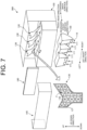
- FIG. 7 is an exploded perspective view illustrating an example of a vehicle lamp 300 according to another embodiment.
- FIG. 8 is a side cross-sectional view illustrating an example of the vehicle lamp 300.
- the vehicle lamp 300 illustrated in IGS. 7 and 8 is, for example, a signal lamp such as a tail lamp. Therefore, in the present embodiment, the front direction is a rear direction (rearward), and the back surface direction is a front direction (forward).
- the vehicle lamp 300 includes a light source portion 110, a reflector 120, a light generating portion 130, a lens member 140, a housing 150, and a reflective portion 160.
- the light source portion 110 includes a light source 111, a support substrate 112, and a heat sink 113.
- the light source 111 is a light source such as an LED or an organic EL, for example.
- the light source 111 is disposed below the light generating portion 130, for example, and a light emitting surface 111a faces toward the back surface direction (forward).
- the light source 111 emits blue light from the light emitting surface 111a, as excitation light, for example.
- the light source 111 is not limited to a light source that emits blue light, and it is possible to use a light source capable of irradiating light (such as purple light, or ultraviolet light) of a short wavelength, as compared with a wavelength of generated light generated in the light generating portion 130 to be described later.
- the light source 111 is provided by the number corresponding to the number of the light generating portions 130 to be described later.
- the support substrate 112 supports the light source 111.
- the support substrate 112 is supported by the housing 150.
- the reflector 120 is disposed on the back side with respect to the light source 111.
- the reflector 120 includes a reflective surface 121 that reflects excitation light to be emitted from the light source 111 upward.
- the reflective surface 121 is provided for each of the light generating portions 130 to be described later. Note that, the reflective surface 121 may be disposed as necessary irrespective of the number and the location of the light generating portions 130.
- the reflector 120 is disposed inside the housing 150.
- the reflector 120 is disposed in such a way as to hide on the back side of the housing 150 so as not to be directly seen, when the vehicle lamp 300 is viewed from the front side.
- the light generating portion 130 includes a holding member 131 and a light emitting layer 132.
- the light generating portion 130 is disposed in such a way that the normal direction R of the light emitting layer 132 is inclined obliquely downward with respect to the front direction.
- the light generating portion 130 is disposed in such a way that the normal direction R of the light emitting layer 132 faces the vehicle outer side (left side) with respect to the front direction.
- a plurality of the light generating portions 130 are disposed in the left-right direction.
- the holding member 131 is made of glass or sapphire.
- a light emitting layer is formed on the holding member 131, and the holding member 131 is bonded to a reflective member made of aluminum or the like. Further, the light emitting layer may be formed on a reflective member made of aluminum or the like.
- the light emitting layer 132 is held on a first surface 131a of the holding member 131.
- the light emitting layer 132 emits generated light by exciting excitation light from the light source 111 by irradiation.
- the light emitting layer 132 is held on the first surface 131a of the holding member 131, for example.
- the light emitting layer 132 is formed into a shape associated with a shape of a tail lamp in a front view, or the like, for example.
- the light emitting layer 132 may include a predetermined pattern P.
- an inorganic material such as CaAlSiN3:Eu (CASN) is used as the light emitting layer 132.
- the light emitting layer 132 can be formed by applying, on the holding member 131, a mixed material of a transparent resin such as silicone, and CASN, and baking. Further, the light emitting layer 132 can be formed by applying, on the holding member 131, a mixed material of an inorganic material such as low melting point glass, and CASN, and baking.
- the light emitting layer 132 When an inorganic material is used as the light emitting layer 132, for example, a substrate made of glass or the like can be used as the holding member 131. Further, other types of materials such as (Sr, Ca)AlSiN3:Eu (SCASN) may be used as the light emitting layer 132.
- a substrate made of glass or the like can be used as the holding member 131.
- other types of materials such as (Sr, Ca)AlSiN3:Eu (SCASN) may be used as the light emitting layer 132.
- the lens member 140 is disposed in the front direction with respect to the light generating portion 130.
- the lens member 140 includes an incident surface 141 and an exit surface 142. Red light, which is generated light from the light generating portion 130, is incident on the incident surface 141.
- the exit surface 142 outputs light incident on the incidence surface 141 in the front direction.
- the lens member 140 transmits red light, and absorbs light different from red light. Therefore, an excitation light component included in external light is absorbed by the lens member 140.
- the lens member 140 is held by the housing 150 or the like, for example.
- the housing 150 is formed by using a resin material of a black color or the like, for example.
- the housing 150 has a rectangular box shape, for example.
- the housing 150 supports or accommodates the light source portion 110, the reflector 120, the light generating portion 130, and the lens member 140.
- the housing 150 includes an accommodation portion 151 and a lamp chamber 152.
- the accommodation portion 151 and the lamp chamber 152 are formed in two stages in the up-down direction.
- the lamp chamber 152 is arranged on the upper stage side, and the accommodation portion 151 is arranged on the lower stage side.
- the accommodation portion 151 accommodates the light source portion 110 and the reflector 120.
- the accommodation portion 151 is surrounded by a lower wall portion 151a in the front-rear direction and the left-right direction.
- the lower wall portion 151a is disposed in such a way as to cover the reflector 120, when the vehicle lamp 300 is viewed from the front side.
- the accommodation portion 151 has a bottom portion 151b at a lower portion thereof.
- the accommodation portion 151 has an opening portion 151c in an upper portion thereof.
- the opening portion 151c has a shape associated with the shape of an upper portion of the reflector 120.
- the lamp chamber 152 is provided in a space surrounded by an upper wall portion 152a and the lens member 140.
- the light generating portion 130 is disposed in the lamp chamber 152.
- the reflective portion 160 is disposed between the light emitting layer 132 and the lens member 140.
- the reflective portion 160 can reflect a part of light from outside of the lens member 140.
- the reflective portion 160 can be formed on a transmissive member 165 disposed between the light emitting layer 132 and the lens member 140, for example.
- FIG. 9 is a diagram schematically illustrating another example of an operation of the vehicle lamp 300.
- illustration of a configuration of the reflector 120, the housing 150, and the like is omitted.
- the light emitting layer 132 when the light emitting layer 132 is irradiated with excitation light Lb, the light emitting layer 132 is excited, and emits red light L.
- a part of the red light L generated in the light emitting layer 132 is output rearward (in the front direction). Further, a part of the red light L generated in the light emitting layer 132 is output forward (in the back surface direction) by the holding member 131, reflected by a reflective layer, and travels rearward.
- the red light L generated in the light emitting layer 132 is output in the front direction, as planar light.
- a part of the red light L is reflected on the reflective portion 160, and a part of the red light L is transmitted and reaches the lens member 140, output from the lens member 140 in the front direction, and irradiated as a pattern of a tail lamp, for example.
- a part of the excitation light Lb which is blue, is absorbed by the lens member 140, which is red.
- FIG. 10 is a diagram schematically illustrating another example of an operation of the vehicle lamp 300.
- illustration of a configuration of the reflector 120, the housing 150, and the like is omitted.
- the light emitting layer 132 is made of an inorganic material, and contains colored particles in a state that excitation light is not irradiated.
- the reflective portion 160 is disposed between the light emitting layer 132 and the lens member 140.
- a part of the light L1 passes through the transmissive member 165 and the reflective portion 160, and reaches the light generating portion 130.
- Light L2 that has reached the light generating portion 130 is scattered by, for example, particles of an inorganic material contained in the light emitting layer 132.
- the scattered light L3 travels rearward, and a part of the scattered light L3 is reflected by the reflective portion 160, and a part of the scattered light L3 is transmitted and output rearward from the lens member 140.
- the amount of external light to be output from the lens member 140 is reduced, as compared with a time when the light is incident on the lens member 140 from the outside. Therefore, it is possible to form an appearance in which the light L3 scattered by the light emitting layer 132 cannot be seen from the outside and only a mirror surface can be seen, or an appearance as if the light emitting layer 132 slightly stands out from the mirror surface.
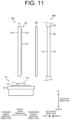
- FIG. 11 is a side view illustrating an example of a vehicle lamp 200 according to another embodiment.
- the vehicle lamp 200 illustrated in FIG. 11 is, for example, a signal lamp such as a tail lamp. Therefore, in the present embodiment, the front direction is a rear direction (rearward), and the back surface direction is a front direction (forward).
- the vehicle lamp 200 includes a light source unit 100.
- the light source unit 100 has a light source portion 10, a light generating portion 20, a lens member 30, and a light absorbing portion 60.
- the light absorbing portion 60 is disposed between a light emitting layer 22 and the lens member 30.
- the light absorbing portion 60 can absorb 1% or more of light entering from outside of the lens member 30.
- a blue filter can be used as the light absorbing portion 60, for example.
- the light absorbing section 60 is capable of absorbing a red component having the same color as excitation light to be emitted from a light source 11, and associated with generated light.
- the light absorbing portion 60 is disposed between the light emitting layer 22 and the lens member 30 separately from the light generating portion 20 and the lens member 30.
- the light absorbing portion 60 is supported by an unillustrated inner housing or the like. Disposing the light absorbing portion 60 separately from the light generating portion 20 and the lens member 30 enables to securely hold the light absorbing portion 60.
- FIG. 12 is a diagram illustrating another example of an arrangement of the light absorbing portion 60.
- the light absorbing portion 60 can be formed on an inner surface of the lens member 30. Forming the light absorbing portion 60 on the inner surface of the lens member 30 enables to integrally handle the light absorbing portion 60 and the lens member 30.
- FIGS. 13 and 14 are diagrams illustrating an example of an operation of the vehicle lamp 200. As illustrated in FIG. 13 , by turning on the light source 11, a part of excitation light Lb to be output from a light emitting surface 11a is irradiated on the light emitting layer 22.
- the light emitting layer 22 When the light emitting layer 22 is irradiated with the excitation light Lb, the light emitting layer 22 is excited and emits red light L. A part of the red light L generated in the light emitting layer 22 is output rearward (in the front direction). Further, when a reflective layer is formed on a planar portion 21b of a holding member 21, a part of the red light L generated in the light emitting layer 22 is output forward (in the back surface direction), reflected by the reflective layer, and travels rearward. Therefore, the red light L generated in the light emitting layer 22 is output in the front direction, as planar light. A part of the red light L is absorbed by the light absorbing portion 60, and a part of the red light L is transmitted and incident on an incident surface 31 of the lens member 30. The red light L incident on the incident surface 31 is output in the front direction from an exit surface 32 of the lens member 30, and irradiated as a pattern of a tail lamp, for example.
- the light emitting layer 22 is made of an inorganic material, and contains colored particles in a state that the excitation light Lb is not irradiated.
- the light absorbing portion 60 is disposed between the light emitting layer 22 and the lens member 30.
- external light Lt when light outside of the lens member 30 enters the lens member 30, light on a short wavelength side with respect to the wavelength of red, which is the color of the lens member 30, is absorbed by the lens member 30.
- the light absorbing portion 60 When the light reaches the light absorbing portion 60, a part of the light is absorbed by the light absorbing portion 60, and a part of the light passes through the light absorbing portion 60, and reaches the light generating portion 20.
- the external light Lt that has reached the light generating portion 20 is scattered by particles of an inorganic material contained in the light emitting layer 22, for example.
- the scattered external light Lt travels rearward, is partially absorbed by the light absorbing portion 60, and output rearward from the lens member 30. Since most of the external light Lt to be output from the lens member 30 is absorbed by the light absorbing portion 60, the amount of light is reduced, as compared with a time when the external light Lt is incident on the lens member 30. Therefore, when the vehicle lamp 200 is viewed from outside of the lens member 30, it is possible to form an appearance in which the light emitting layer 22 is not visually recognized, that is, an appearance as if the light emitting layer 22 is not present inside the vehicle lamp 200.
- the light source unit 100 includes the light generating portion 20 including the light source 11 that emits excitation light, the light emitting layer 22 that is constituted by using an inorganic material and emits generated light by irradiation of the excitation light, and the holding member 21 that holds the light emitting layer 22; the lens member 30 that irradiates the generated light from the light emitting layer 22 in the front direction in a vehicle-mounted state; and the light absorbing portion 60 that is disposed between the light emitting layer 22 and the lens member 30, and absorbs a part of a wavelength component among light from outside of the lens member 30 being associated with the generated light.
- the lens member 30 when light outside of the lens member 30 enters the lens member 30, a part of the light is absorbed by the light absorbing portion 60, a part of the light is transmitted through the light absorbing portion 60, and reaches the light generating portion 20.
- the external light that has reached the light generating portion 20 is scattered by particles of an inorganic material contained in the light emitting layer 22, for example, the scattered light travels rearward, and a part of the scattered light is absorbed by the light absorbing portion 60, and output rearward from the lens member 30. Therefore, when the vehicle lamp 200 is viewed from outside of the lens member 30, it appears as if the light emitting layer 22 is not present inside the vehicle lamp 200. This enables to provide the light source unit 100 having a good appearance.
- excitation light is blue, and generated light and the lens member 30 are red. According to this configuration, the excitation light scattered or the like without being absorbed by the light emitting layer 22 can be absorbed by the lens member 30. Therefore, it is possible to suppress the excitation light from leaking to outside of the vehicle lamp 200.
- the light absorbing portion 60 may be a blue filter. According to this configuration, it is easy to form a configuration in which excitation light of a red color is absorbed.
- the light absorbing portion 60 is provided separately from the light generating portion 20 and the lens member 30. According to this configuration, the degree of freedom of the layout of the light absorbing portion 60 is enhanced.
- the light absorbing portion 60 is formed on the lens member 30. According to this configuration, it is possible to integrally handle the light absorbing portion 60 and the lens member 30.
- the light absorbing portion 60 is formed in such a way that the light emitting layer 22 is not visually recognized, when inside of the light source unit 100 is viewed from outside of the lens member 30 at a time of turning off the light source 11. According to this configuration, it is possible to provide the light source unit 100 having a good appearance.
- the vehicle lamp 200 according to the present embodiment includes the above-described light source unit 100 for a vehicle lamp. According to this configuration, it is possible to provide a vehicle lamp having a good appearance.
- FIG. 7 is an exploded perspective view illustrating an example of a vehicle lamp 300 according to another embodiment.
- FIG. 15 is a side cross-sectional view illustrating an example of the vehicle lamp 300.
- the vehicle lamp 300 illustrated in FIGS. 7 and 15 is, for example, a signal light such as a tail lamp. Therefore, in the present embodiment, the front direction is a rear direction (rearward), and the back surface direction is a front direction (forward).
- the vehicle lamp 300 includes a light source portion 110, a reflector 120, a light generating portion 130, a lens member 140, a housing 150, and a light absorbing portion 180.
- the light absorbing portion 180 is disposed between a light emitting layer 132 and the lens member 140.
- the light absorbing portion 180 can absorb 1% or more of light entering from outside of the lens member 140.
- a blue filter can be used as the light absorbing portion 180, for example.
- the light absorbing portion 180 is capable of absorbing a red component having the same color as excitation light to be emitted from a light source 111, and associated with generated light.
- FIG. 16 is a diagram schematically illustrating another example of an operation of the vehicle lamp 300.
- illustration of a configuration of the reflector 120, the housing 150, and the like is omitted.
- the light emitting layer 132 when a light emitting layer 132 is irradiated with excitation light, the light emitting layer 132 is excited, and emits red light L.
- the red light L generated in the light emitting layer 132 is output in the front direction, as planar light.
- a part of the red light L is absorbed by the light absorbing portion 180, and a part of the red light L is transmitted and output from the lens member 140 in the front direction, and irradiated as a pattern of a tail lamp, for example.
- the red light L is not generated from the light emitting layer 132.
- the light emitting layer 132 is made of an inorganic material, and contains colored particles in a state that excitation light is not irradiated.
- external light Ls when light outside the lens member 140 enters the lens member 140, light on a short wavelength side with respect to the wavelength of red, which is the color of the lens member 140, is absorbed by the lens member 140.
- the lens member 140 When light Lu that has entered the lens member 140 reaches the light absorbing portion 180, which is a blue filter, most of the light Lu is absorbed by the light absorbing portion 180. Therefore, when the vehicle lamp 300 is viewed from outside of the lens member 140, it is possible to form an appearance in which the light emitting layer 132 is not visually recognized, that is, an appearance as if the light emitting layer 132 is not present inside the vehicle lamp 300.
- FIG. 17 is an explosive perspective view illustrating an example of a vehicle lamp 200 according to the present embodiment.
- FIG. 18 is a side cross-sectional view illustrating an example of the vehicle lamp 200.
- the vehicle lamp 200 illustrated in FIGS. 17 and 18 is, for example, a signal lamp such as a tail lamp. Therefore, in the present embodiment, the front direction is a rear direction (rearward), and the back surface direction is a front direction (forward).
- the vehicle lamp 200 includes a light source portion 10, a reflector 120, a light generating portion 130, a lens member 140, and a housing 150.
- the light source portion 10 includes a light source 11, a support substrate 12, and a heat sink 13.
- the light source 11 is a light source such as an LED or an organic EL, for example.
- the light source 11 is disposed below the light generating portion 130, for example, and a light emitting surface 11a faces in the back surface direction (forward).
- the light source 11 emits blue light from the light emitting surface 11a, as excitation light, for example.
- the light source 11 is not limited to a light source that emits blue light, and it is possible to use a light source capable of irradiating light (such as purple light, or ultraviolet light) of a short wavelength, as compared with a wavelength of generated light generated in the light generating portion 130 to be described later.
- the light source 11 is provided by the number corresponding to the number of the light generating portions 130 to be described later.
- the support substrate 12 supports the light source 11.
- the support substrate 12 is supported by the housing 150.
- the reflector 120 is disposed on the back side with respect to the light source 11.
- the reflector 120 includes a reflective surface 121 that reflects excitation light to be emitted from the light source 11 upward.
- the reflective surface 121 is provided for each of the light generating portions 130 to be described later. Note that, the reflective surface 121 may be disposed as necessary irrespective of the number and the location of the light generating portions 130.
- the reflector 120 is disposed inside the housing 150.
- the reflector 120 is disposed in such a way as to hide on the back side of the housing 150 so as not to be directly seen, when the vehicle lamp 200 is viewed from the front side.
- the light generating portion 130 includes a holding member 131 and a light emitting layer 132.
- the light generating portion 130 is disposed in such a way that the normal direction R of the light emitting layer 132 is inclined obliquely downward with respect to the front direction.
- the light generating portion 130 is disposed in such a way that the normal direction R of the light emitting layer 132 faces the vehicle outer side (left side) with respect to the front direction.
- a plurality of the light generating portions 130 are arranged in the left-right direction.
- the holding member 131 is capable of transmitting excitation light to be emitted from the light source 11.
- the holding member 131 is able to guide the excitation light into the holding member 131 by transmitting the excitation light, and irradiate the light over the entire surface of the light emitting layer 132 to be described later.
- the holding member 131 has a rectangular plate shape, for example, and is capable of transmitting generated light emitted by the light emitting layer 132 to be described later.
- glass or the like is used as the holding member 131 as described above.
- the light emitting layer 132 is held on a first surface 131a of the holding member 131.
- the light emitting layer 132 emits generated light by exciting excitation light from the light source 11 by irradiation.
- the light emitting layer 132 is held on the first surface 131a of the holding member 131, for example.
- the light emitting layer 132 is formed into a shape associated with a shape of a tail lamp in a front view, or the like, for example.
- the light emitting layer 132 may have a predetermined pattern P.
- the light emitting layer 132 for example, an organic material obtained by doping about 5 % of a guest material such as acetylacetone into a host material such as polyvinyl carbazole is used. In this case, the light emitting layer 132 emits red light, as generated light.
- a guest material such as acetylacetone
- a host material such as polyvinyl carbazole
- the light emitting layer 132 emits red light, as generated light.
- the combination of the host material and the guest material is not limited to the above.
- the light emitting layer 132 is made of an organic material
- the light emitting layer 132 can be formed by co-depositing a host material and a guest material on the holding member 131.
- the light emitting layer 132 may be formed by a wet method such as a spin coating method or a spray method.
- a substrate made of glass or the like can be used as the holding member 131.
- an inorganic material such as CaAlSiN3:Eu (CASN) may be used as the light emitting layer 132.
- the light emitting layer 132 can be formed by applying, on the holding member 131, a mixed material of a transparent resin such as silicone, and CASN, and baking. Further, the light emitting layer 132 can be formed by applying, on the holding member 131, a mixed material of an inorganic material such as low melting point glass, and CASN, and baking.
- the light emitting layer 132 When an inorganic material is used as the light emitting layer 132, a substrate made of glass or the like can be used as the holding member 131. Further, other types of materials such as (Sr, Ca)AlSiN3:Eu (SCASN) may be used as the light emitting layer 132, for example.
- the lens member 140 is disposed in the front direction with respect to the light generating portion 130.
- the lens member 140 includes an incident surface 141 and an exit surface 142. Red light, which is generated light from the light generating portion 130, is incident on the incident surface 141.
- the exit surface 142 outputs light incident on the incidence surface 141 in the front direction.
- the lens member 140 transmits red light and absorbs light different from red light. Therefore, an excitation light component included in external light is absorbed by the lens member 140.
- the lens member 140 is held by the housing 150 or the like, for example.
- the housing 150 is formed by using a resin material of a black color or the like, for example.
- the housing 150 has a rectangular box shape, for example.
- the housing 150 supports or accommodates the light source portion 10, the reflector 120, the light generating portion 130, and the lens member 140.
- the housing 150 includes an accommodation portion 151 and a lamp chamber 152.
- the accommodation portion 151 and the lamp chamber 152 are formed in two stages in the up-down direction.
- the lamp chamber 152 is arranged on the upper stage side, and the accommodation portion 151 is arranged on the lower stage side.
- the accommodation portion 151 accommodates the light source portion 10 and the reflector 120.
- the accommodation portion 151 is surrounded by a lower wall portion 151a in the front-rear direction and the left-right direction.
- the lower wall portion 151a is disposed in such a way as to cover the reflector 120, when the vehicle lamp 200 is viewed from the front side.
- the accommodation portion 151 has a bottom portion 151b at a lower portion thereof.
- the accommodation portion 151 has an opening portion 151c in an upper portion thereof.
- the opening portion 151c has a shape associated with the shape of an upper portion of the reflector 120.
- the lamp chamber 152 is provided in a space surrounded by an upper wall portion 152a and the lens member 140.
- the light generating portion 130 is disposed in the lamp chamber 152.
- FIGS. 19 to 21 are diagrams illustrating an example of an operation of the vehicle lamp 200.
- a part of excitation light Lb to be output from the light emitting surface 11a is irradiated to the light emitting layer 132 directly or by transmitting through the holding member 131.
- the light emitting layer 132 When the light emitting layer 132 is irradiated with the excitation light Lb, the light emitting layer 132 is excited, and emits red light L. A part of the red light L generated in the light emitting layer 132 is output rearward (in the front direction). In addition, when a reflective layer is formed on a second surface 131b of the holding member 131, a part of the red light L generated in the light emitting layer 132 is output forward (in the back surface direction), reflected by the reflective layer, and travels rearward. Therefore, the red light L generated in the light emitting layer 132 is output in the front direction, as planar light. The red light L is incident on the incident surface 141 of the lens member 140, output from the exit surface 142 in the front direction, and irradiated as a pattern of a tail lamp, for example.
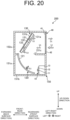
- FIG. 20 illustrates an example in which the light emitting layer 132 is formed by using an organic material.
- the light emitting layer 132 is made of an organic material
- external light Lt when light outside of the lens member 140 enters the lens member 140, light on a short wavelength side with respect to the wavelength of red, which is the color of the lens member 140, is absorbed by the lens member 140.
- the external light Lt reaches the light generating portion 130, the external light Lt is reflected by a light reflective member 133 on the second surface 131b, and reaches the reflector 120.
- the external light Lt that has reached the reflector 120 is reflected by the reflector 120, returns to the light generating portion 130, is reflected by the light reflective member 133 of the light generating portion 130, and output from the lens member 140 toward the front side.
- FIG. 21 illustrates an example in which the light emitting layer 132 is formed by using an inorganic material. As illustrated in FIG. 21 , in a configuration in which the light emitting layer 132 is made of an inorganic material, the light emitting layer 132 contains colored particles in a state that the excitation light Lb is not irradiated.
- external light Lt when light outside of the lens member 140 enters the lens member 140, light on a short wavelength side with respect to the wavelength of red, which is the color of the lens member 140, is absorbed by the lens member 140.
- the external light Lt reaches the light generating portion 130, the external light Lt is scattered by particles of an inorganic material contained in the light emitting layer 132, for example.
- the scattered external light Lt travels rearward, and is output rearward from the lens member 140.
- an absorbing member that absorbs red light as exemplified by a blue transparent substrate or the like may be disposed between the light emitting layer 132 and the lens member 140. This enables to absorb a part of the external light Lt scattered on the light emitting layer 132. In this configuration, when inside of the vehicle lamp 200 is viewed from outside of the lens member 140 in a state that the light source 11 is turned off, it is possible to form an appearance as if the light emitting layer 132 cannot be seen inside the vehicle lamp 200.
- the vehicle lamp 200 includes the light generating portion 130 including the light source 11 that emits excitation light, the reflector 120 that reflects the excitation light from the light source 11, and the light emitting layer 132 that emits generated light by irradiation of the excitation light and the holding member 131 that holds the light emitting layer 132; and the lens member 140 that is disposed on the front side with respect to the light emitting layer 132, and irradiates the generated light from the light emitting layer 132 in the front direction in a vehicle-mounted state.
- the light source 11 emits excitation light
- the reflector 120 reflects the light
- the light emitting layer 132 outputs generated light by receiving irradiation of the excitation light
- the lens member 140 is disposed on the front side with respect to the light emitting layer 132 and irradiates the generated light from the light emitting layer 132 in the front direction in a vehicle-mounted state. Therefore, it is possible to arrange the light source 11, the reflector 120, the light generating portion 130, and the lens member 140 in the front-back direction in a compact manner. This enables to provide the vehicle lamp 200 capable of arranging each part in a compact manner.
- the light generating portion 130 is disposed in such a way that a normal direction of the light emitting layer 132 is inclined obliquely downward with respect to the front direction. According to this configuration, since the area of the light emitting layer 132 when viewed from below is increased, the light emitting layer 132 can easily receive irradiation of excitation light from below. This enables to generate generated light efficiently.
- excitation light is blue, and generated light and the lens member 140 are red. According to this configuration, excitation light scattered or the like without being absorbed by the light emitting layer 132 can be absorbed by the lens member 140. Therefore, it is possible to suppress the excitation light from leaking to outside of the vehicle lamp 200.
- a plurality of the light generating portions 130 are arranged in the left-right direction in a vehicle-mounted state. According to this configuration, a plurality of patterns of the light emitting layer 132 can be seen in the left-right direction, when the vehicle lamp 200 is viewed from the front side. This enables to provide the vehicle lamp 200 having a good appearance.
- the vehicle lamp 200 further includes the housing 150 that supports the light source 11, the reflector 120, the light generating portion 130, and the lens member 140.
- the housing 150 is disposed in such a way as to cover the reflector 120 when viewed from the front side, and defines a lamp chamber between the lens member 140 and itself.
- the light generating portion 130 is disposed inside the lamp chamber. According to this configuration, a state in which the reflector 120 is hidden by the housing 150 and cannot be seen when viewed from the front side is achieved. This enables to provide the vehicle lamp 200 having a good appearance.
- the holding member 131 includes the light reflective member 133 that is formed into a plate-like shape, is capable of transmitting excitation light and generated light, and reflects the excitation light and the generated light on a second surface opposite to a first surface on which the light emitting layer 132 is held. According to this configuration, it is possible to reflect excitation light that transmits through the holding member 131 among excitation light to be irradiated on the light generating portion 130 inward, and allow the light to reach the light emitting layer 132. Further, it is possible to reflect generated light generated in the light emitting layer 132 and irradiated toward the back side inward toward the front side.
- FIG. 22 is a side cross-sectional view illustrating another example of a vehicle lamp according to another embodiment.
- a light reflective member 134 may be a plate-like member including a cover portion 134a that covers a second surface 131b, and a bulging portion 134b bulging upward from the second surface 131b.
- the bulging portion 134b is bent toward the front side.
- the bulging portion 134b is disposed in such a way as to protrude toward the front side with respect to a light emitting layer 132.
- the light reflective member 134 includes the cover portion 134a that covers the second surface 131b, and the bulging portion 134b bulging upward from the second surface 131b.
- the bulging portion 134b is bent toward the front side, and protrudes in the front direction with respect to the light emitting layer 132. According to this configuration, excitation light Lb that has passed through the light emitting layer 132 upward from a light source 11 can be reflected downward, and reach the light emitting layer 132. Therefore, generated light L can be efficiently generated in the light emitting layer 132.
- FIG. 23 is a side cross-sectional view illustrating another example of a vehicle lamp according to another embodiment.
- a first surface 135a of a holding member 135 may be a light reflective surface that reflects excitation light and generated light
- a light emitting layer 132 may be formed on the first surface 135a, which is a light reflective surface.
- the holding member 135 may include a protruding portion 135b bulging upward of the light emitting layer 132, and protruding toward the front side of the light emitting layer 132.
- the holding member 135 has a plate-like shape, and includes the first surface 135a that reflects excitation light and generated light.
- the light emitting layer 132 is formed on the first surface 135a.
- the holding member 135 includes the protruding portion 135b bulging upward of the light emitting layer 132 and protruding toward the front side of the light emitting layer 132. According to this configuration, excitation light Lb that has passed through the light emitting layer 132 upward from a light source 11 can be reflected downward, and reach the light emitting layer 132. Therefore, generated light L can be efficiently generated in the light emitting layer 132. Further, as compared with the configuration illustrated in FIG. 22 , the number of parts can be reduced.
Landscapes
- Engineering & Computer Science (AREA)
- General Engineering & Computer Science (AREA)
- Physics & Mathematics (AREA)
- Microelectronics & Electronic Packaging (AREA)
- Optics & Photonics (AREA)
- Non-Portable Lighting Devices Or Systems Thereof (AREA)
Abstract
Description
- The present invention relates to a light source unit for a vehicle lamp, and a vehicle lamp.
- A light source unit for a vehicle including an excitation light source, a light emitting layer that is constituted of an organic material and emits generated light by irradiating excitation light from the excitation light source, and a lens member that irradiates the excitation light from the light emitting layer is known (e.g., see Patent Literature 1). Further, a vehicle lamp including a light source, a reflector that reflects excitation light from the light source, a light emitting layer that emits generated light by irradiation of the excitation light reflected by the reflector, and a lens member that irradiates the excitation light from the light emitting layer is known (e.g., see Patent Literature 1).
- PTL 1:
Japanese Unexamined Patent Application Publication No. 2020-190255 - In the light source unit, using an inorganic material as the light emitting layer has been proposed. Unlike a film-like organic material, the inorganic material contains colored particles. Therefore, at a time of turning off the light source, external light such as sunlight passes through the lens member, reaches the light emitting layer, and is scattered by the particles. In this case, a light emitting surface appears to be present from outside of the lens member, and improvement may be required in terms of appearance. In addition, in the vehicle lamp as described above, it is required to arrange each part including the light source, the reflector, the light emitting layer, the lens member, and the like in a compact manner.
- The present invention has been made in view of the above, and an object of the invention is to provide a light source for a vehicle lamp having a good appearance, a vehicle lamp, and a vehicle lamp capable of arranging each part in a compact manner.
- A light source unit for a vehicle lamp according to the present invention includes: a light generating portion including a light source that emits excitation light, a light emitting layer that is constituted by using an inorganic material, and emits generated light by irradiation of the excitation light, and a holding member that holds the light emitting layer; a lens member that irradiates the generated light from the light emitting layer in a front direction in a vehicle-mounted state; and a reflective portion that is disposed between the light emitting layer and the lens member, is capable of reflecting a part of light from outside of the lens member, and is capable of transmitting the generated light generated in the light emitting layer. Further, a light source unit for a vehicle lamp according to the present invention includes: a light generating portion including a light source that emits excitation light, a light emitting layer that is constituted by using an inorganic material, and emits generated light by irradiation of the excitation light, and a holding member that holds the light emitting layer; a lens member that irradiates the generated light from the light emitting layer in a front direction in a vehicle-mounted state; and a light absorbing portion that is disposed between the light emitting layer and the lens member, and absorbs a part of a wavelength component among light from outside of the lens member being associated with the generated light. Further, a vehicle lamp according to the present invention includes: a light source that emits excitation light; a reflector that reflects the excitation light from the light source; a light generating portion including a light emitting layer that emits generated light by irradiation of the excitation light, and a holding member that holds the light emitting layer; and a lens member that is disposed on a front side with respect to the light emitting layer, and irradiates the generated light from the light emitting layer in a front direction in a vehicle-mounted state.
- In the light source unit for a vehicle lamp, the reflective portion may be formed by using a metal vapor deposition film.
- In the light source unit for a vehicle lamp, the excitation light may be blue, and the generated light and the lens member may be red.
- In the light source unit for a vehicle lamp, the reflective portion may be formed in such a way as to cover the light emitting layer.
- In the light source unit for a vehicle lamp, the light absorbing portion may be a blue filter.
- In the light source unit for a vehicle lamp, the light absorbing portion may be provided separately from the light generating portion and the lens member.
- In the light source unit for a vehicle lamp, the light absorbing portion may be formed on the lens member.
- In the light source unit for a vehicle lamp, the light absorbing portion is formed in such a way that the light emitting layer is not visually recognized, when inside of the light source unit is viewed from outside of the lens member at a time of turning off the light source.
- In the light source unit for a vehicle lamp, the holding member may be capable of transmitting the generated light, the light generating portion may be formed on a first surface of the holding member, and the reflective portion may be formed on a second surface opposite to the first surface of the holding member.
- The light source unit for a vehicle lamp may further include a transmissive member that transmits the generated light generated by the light generating portion, between the light emitting layer and the lens member, and the reflective portion may be formed on the transmissive member.
- In the light source unit for a vehicle lamp, the reflective portion may be formed on the lens member.
- In the light source unit for a vehicle lamp, the reflective portion may be formed in such a way as to be visually recognized as a shape of a mirror surface, when inside of the light source unit is viewed from outside of the lens member.
- A vehicle lamp according to the present invention includes the above-described light source unit for a vehicle lamp.
- In the vehicle lamp, the light generating portion may be disposed in such a way that a normal direction of the light emitting layer is inclined obliquely downward with respect to a front direction.
- In the vehicle lamp, the excitation light may be blue, and the generated light and the lens member may be red.
- In the vehicle lamp, a plurality of the light generating portions may be arranged in a left-right direction in a vehicle-mounted state.
- The vehicle lamp may further include a housing that supports the light source, the reflector, the light generating portion, and the lens member. The housing may be disposed in such a way as to cover the reflector when viewed from a front side, and may define a lamp chamber between the lens member and itself. The light generating portion may be disposed inside the lamp chamber.
- In the vehicle lamp, the holding member may be formed into a plate-like shape, may be capable of transmitting the excitation light and the generated light, and may include a light reflective member that reflects the excitation light and the generated light on a second surface opposite to a first surface on which the light emitting layer is held.
- In the vehicle lamp, the light reflective member may include a cover portion that covers the second surface, and a bulging portion bulging upward from the second surface. The bulging portion may be bent toward a front side, and protrude in a front direction with respect to the light emitting layer.
- In the vehicle lamp, the holding member may have a plate-like shape, and include a light reflective surface that reflects the excitation light and the generated light. The light emitting layer may be formed on the light reflective surface. The holding member may include a protruding portion bulging upward of the light emitting layer, and protruding toward a front side of the light emitting layer.
- According to the present invention, it is possible to provide a light source unit for a vehicle lamp having a good appearance, and a vehicle lamp. Further, it is possible to provide a vehicle lamp capable of arranging each part in a compact manner.
-
- [
FIG. 1] FIG. 1 is a side view illustrating an example of a vehicle lamp according to the present embodiment. - [
FIG. 2] FIG. 2 is a diagram illustrating another example of an arrangement of a reflective portion. - [
FIG. 3] FIG. 3 is a diagram illustrating another example of an arrangement of the reflective portion. - [
FIG. 4] FIG. 4 is a diagram illustrating another example of an arrangement of the reflective portion. - [
FIG. 5] FIG. 5 is a diagram illustrating an example of an operation of the vehicle lamp. - [
FIG. 6] FIG. 6 is a diagram illustrating an example of an operation of the vehicle lamp. - [
FIG. 7] FIG. 7 is an exploded perspective view illustrating another example of a vehicle lamp according to another embodiment. - [
FIG. 8] FIG. 8 is a side cross-sectional view illustrating another example of the vehicle lamp. - [
FIG. 9] FIG. 9 is a diagram illustrating another example of an operation of the vehicle lamp. - [
FIG. 10] FIG. 10 is a diagram illustrating another example of an operation of the vehicle lamp. - [
FIG. 11] FIG. 11 is a side view illustrating an example of a vehicle lamp according to another embodiment. - [
FIG. 12] FIG. 12 is a diagram illustrating another example of an arrangement of a light absorbing portion. - [
FIG. 13] FIG. 13 is a diagram illustrating another example of an operation of the vehicle lamp. - [
FIG. 14] FIG. 14 is a diagram illustrating another example of an operation of the vehicle lamp. - [
FIG. 15] FIG. 15 is a side cross-sectional view illustrating another example of the vehicle lamp. - [
FIG. 16] FIG. 16 is a diagram schematically illustrating another example of an operation of the vehicle lamp. - [
FIG. 17] FIG. 17 is an exploded perspective view illustrating an example of a vehicle lamp according to another embodiment. - [
FIG. 18] FIG. 18 is a side cross-sectional view illustrating another example of the vehicle lamp. - [
FIG. 19] FIG. 19 is a diagram illustrating another example of an operation of the vehicle lamp. - [
FIG. 20] FIG. 20 is a diagram illustrating another example of an operation of the vehicle lamp. - [
FIG. 21] FIG. 21 is a diagram illustrating another example of an operation of the vehicle lamp. - [
FIG. 22] FIG. 22 is a side cross-sectional view illustrating another example of a vehicle lamp according to another embodiment. - [
FIG. 23] FIG. 23 is a side cross-sectional view illustrating another example of a vehicle lamp according to another embodiment. - In the following, an embodiment of a light source unit for a vehicle lamp, and a vehicle lamp according to the present invention is described with reference to the drawings. Note that, the present invention is not limited to this embodiment. In addition, constituent elements in the following embodiment include those that can be easily replaced by those skilled in the art, or those that are substantially the same. In the following description, each of a front-rear direction, an up-down direction, and a left-right direction is a direction in a vehicle-mounted state in which a light source unit for a vehicle lamp is mounted on a vehicle, and indicates a direction when a traveling direction of the vehicle is viewed from a driver's seat. Note that, in the present embodiment, it is assumed that the up-down direction is in parallel to a vertical direction, and the left-right direction is a horizontal direction. Further, regarding a front direction and a back surface direction, it is assumed that a direction in which light is emitted from a light source unit for a vehicle lamp or from a vehicle lamp is the front direction, and a direction opposite to the front direction is the back surface direction.
-
FIG. 1 is a side view illustrating an example of avehicle lamp 200 according to the present embodiment. Thevehicle lamp 200 illustrated inFIG. 1 is, for example, a signal lamp such as a tail lamp. Therefore, in the present embodiment, the front direction is a rear direction (rearward), and the back surface direction is a front direction (forward). As illustrated inFIG. 1 , thevehicle lamp 200 includes alight source unit 100. - The
light source unit 100 includes alight source portion 10, alight generating portion 20, alens member 30, and areflective portion 40. - The
light source portion 10 includes alight source 11, asupport substrate 12, and aheat sink 13. Thelight source 11 is a light source such as an LED or an organic EL, for example. Thelight source 11 is disposed below thelight generating portion 20, for example, and alight emitting surface 11a faces toward the light generating portion 20 (upward). Thelight source 11 emits blue light from thelight emitting surface 11a, as excitation light, for example. Note that, thelight source 11 is not limited to a light source that emits blue light, and it is possible to use a light source capable of irradiating light (such as purple light, or ultraviolet light) of a short wavelength, as compared with a wavelength of generated light generated in thelight generating portion 20 to be described later. - The
support substrate 12 supports thelight source 11. Thesupport substrate 12 is supported by theheat sink 13. Theheat sink 13 is held by an unillustrated bracket or the like, for example. - The
light generating portion 20 includes a holdingmember 21 and alight emitting layer 22. The holdingmember 21 is supported by an unillustrated bracket or the like independently of thelight source portion 10. Since the holdingmember 21 is provided independently of thelight source portion 10, the degree of freedom of the layout of thelight source portion 10 and thelight generating portion 20 is enhanced. Therefore, it is possible to flexibly set the arrangement of thelight source portion 10 and thelight generating portion 20 according to a design content. - The holding
member 21 is made of aluminum. Generated light from thelight emitting layer 22 is reflected rearward, and a front luminance of the lamp can be enhanced. In the present embodiment, the holdingmember 21 is made of aluminum, but may be made of glass or sapphire. Alternatively, thelight emitting layer 22 may be formed on the holdingmember 21 made of glass or sapphire, and the holdingmember 21 may be bonded to a reflective member made of aluminum or the like. - The
light emitting layer 22 is held on the holdingmember 21. Thelight emitting layer 22 emits generated light by exciting excitation light from thelight source 11 by irradiation. Thelight emitting layer 22 is held on aplanar portion 21a of the holdingmember 21, for example. Thelight emitting layer 22 is formed into a shape associated with a shape of a tail lamp in a front view, or the like, for example. In the present embodiment, as thelight emitting layer 22, for example, an inorganic material such as CaAlSiN3:Eu (CASN), (Sr, Ca)AlSiN3:Eu (SCASN), or the like is used. - The
lens member 30 is disposed in the front direction with respect to thelight generating portion 20. Thelens member 30 includes anincident surface 31, and anexit surface 32. Red light, which is generated light from thelight generating portion 20 is incident on theincident surface 31. Theexit surface 32 outputs light incident on theincident surface 31 in the front direction. Thelens member 30 transmits red light, and absorbs light different from red light. Therefore, an excitation light component included in external light is absorbed by thelens member 30. Thelens member 30 is held by aninner panel 50 or the like, for example. - The
reflective portion 40 is disposed between the light emittinglayer 22 and thelens member 30. Thereflective portion 40 is capable of reflecting a part of external light from thelens member 30. Thereflective portion 40 is capable of transmitting generated light generated by thelight emitting layer 22. Thereflective portion 40 is formed by using a metal vapor deposition film made of aluminum, silver or the like, for example. Thereflective portion 40 is capable of reflecting light among light that reaches thereflective portion 40 with a reflectance of 10 % or more but less than 100 %, for example. - The
reflective portion 40 can be formed on atransmissive member 45 disposed between the light emittinglayer 22 and thelens member 30, for example. As thetransmissive member 45, glass substrate or the like capable of transmitting generated light generated by thelight generating portion 20. Forming thereflective portion 40 on thetransmissive member 45 enables to securely hold thereflective portion 40. -
FIGS. 2 to 4 are diagrams illustrating another example of an arrangement of thereflective portion 40. As illustrated inFIG. 2 , thereflective portion 40 can be formed in such a way as to cover thelight emitting layer 22, for example. In this case, thereflective portion 40 can be formed by vapor deposition or the like on thelight emitting layer 22, after thelight emitting layer 22 is formed. Forming thereflective portion 40 in such a way as to cover thelight emitting layer 22 enables to integrally handle thelight generating portion 20 and thereflective portion 40. - As illustrated in
FIG. 3 , it is possible to configure in such a way that thelight emitting layer 22 is formed on a planar portion (first surface) 21b of the holdingmember 21, and thereflective portion 40 is formed on a planar portion (second surface) 21a of the holdingmember 21, for example. In this case, after thelight emitting layer 22 is formed, or before thelight emitting layer 22 is formed, thereflective portion 40 can be formed by vapor deposition or the like on theplanar portion 21a. Forming thereflective portion 40 on theplanar portion 21a of the holdingmember 21 enables to integrally handle thelight generating portion 20 and thereflective portion 40. - As illustrated in
FIG. 4 , thereflective portion 40 can be formed on theincident surface 31 of thelens member 30. Forming thereflective portion 40 on theincident surface 31 of thelens member 30 enables to integrally handle thereflective portion 40 and thelens member 30. - Next, an operation of the
vehicle lamp 200 configured as described above is described.FIGS. 5 and6 are diagrams illustrating an example of an operation of thevehicle lamp 200.FIGS. 5 and6 illustrate, as a configuration of thelight source unit 100, a case of the configuration illustrated inFIG. 1 , but similar description is also available for a configuration illustrated fromFIGS. 2 to 4 . As illustrated inFIG. 5 , by turning on thelight source 11, a part of excitation light Lb to be output from thelight emitting surface 11a is irradiated to thelight emitting layer 22 directly or by transmitting through the holdingmember 21. - When the
light emitting layer 22 is irradiated with the excitation light Lb, thelight emitting layer 22 is excited, and emits red light L. A part of the red light L generated in thelight emitting layer 22 is output rearward (in the front direction). Further, when a reflective layer is formed on theplanar portion 21b of the holdingmember 21, a part of the red light L generated in thelight emitting layer 22 is output forward (in the back surface direction), reflected by the reflective layer, and travels rearward. Therefore, the red light L generated in thelight emitting layer 22 is output in the front direction, as planar light. A part of the red light L is reflected by thereflective portion 40, and a part of the red light L is transmitted and incident on theincident surface 31 of thelens member 30. The red light L incident on theincident surface 31 is output in the front direction from theexit surface 32 of thelens member 30, and irradiated as a pattern of a tail lamp, for example. - Further, when the
light source 11 is turned off, as illustrated inFIG. 6 , since the excitation light Lb is not emitted from thelight source 11, the red light L is not generated from thelight emitting layer 22. In the present embodiment, thelight emitting layer 22 is made of an inorganic material, and contains colored particles in a state that the excitation light Lb is not irradiated. Meanwhile, in the present embodiment, thereflective portion 40 is disposed between the light emittinglayer 22 and thelens member 30. - In this configuration, when light outside of the lens member 30 (hereinafter, referred to as external light Lt) enters the
lens member 30, light on a short wavelength side with respect to the wavelength of red light, which is the color of thelens member 30, is absorbed by thelens member 30. When the external light Lt reaches thereflective portion 40, a part of the external light Lt is reflected and output rearward from thelens member 30. Therefore, when inside of thevehicle lamp 200 is viewed from outside of thelens member 30, it is possible to form an appearance in which inside of thevehicle lamp 200 is visually recognized as a shape of a mirror surface, that is, an appearance as if a mirror surface is present inside thevehicle lamp 200. - Further, a part of the external light Lt passes through the
transmissive member 45 and thereflective portion 40, and reaches thelight generating portion 20. The external light Lt that has reached thelight generating portion 20 is scattered by particles of an inorganic material contained in thelight emitting layer 22, the scattered light travels rearward, a part of the scattered light is reflected by thereflective portion 40, and a part of the scattered light is transmitted and output rearward from thelens member 30, for example. The amount of the external light Lt to be output from thelens member 30 is reduced, as compared with a time when the external light Lt is incident on thelens member 30 from the outside. Therefore, it is possible to form an appearance in which the external light Lt scattered by thelight emitting layer 22 cannot be seen from the outside and only a mirror surface can be seen, or an appearance as if thelight emitting layer 22 slightly stands out from the mirror surface. - As described above, the
light source unit 100 according to the present embodiment includes thelight generating portion 20 including thelight source 11 that emits excitation light, thelight emitting layer 22 that is constituted by using an inorganic material, and emits generated light by irradiation of the excitation light, and the holdingmember 21 that holds thelight emitting layer 22; thelens member 30 that irradiates the generated light from thelight emitting layer 22 in the front direction in a vehicle-mounted state; and thereflective portion 40 that is disposed between the light emittinglayer 22 and thelens member 30, is capable of reflecting a part of light from outside of thelens member 20, and is capable of transmitting the generated light generated in thelight emitting layer 22. - According to this configuration, when light from outside of the
lens member 30 enters thelens member 30, a part of the light is reflected and output rearward from thelens member 30. Therefore, when thevehicle lamp 200 is viewed from outside of thelens member 30, it appears as if a mirror surface is present inside thevehicle lamp 200. This enables to provide thelight source unit 100 having a good appearance. - In the
light source unit 100 for a vehicle lamp according to the present embodiment, thereflective portion 40 is formed by using a metal vapor deposition film. According to this configuration, it is easy to achieve a configuration in which a part of light from outside of thelens member 30 is reflectable, and generated light generated in thelight emitting layer 22 is transmissible. - In the
light source unit 100 for a vehicle lamp according to the present embodiment, excitation light is blue, and generated light and thelens member 30 are red. According to this configuration, excitation light scattered or the like without being absorbed by thelight emitting layer 22 can be absorbed by thelens member 30. Therefore, it is possible to suppress the excitation light from leaking to outside of thevehicle lamp 200. - In the
light source unit 100 for a vehicle lamp according to the present embodiment, thereflective portion 40 may be formed in such a way as to cover thelight emitting layer 22. According to this configuration, it is possible to form an appearance as if a mirror surface is present at a position associated with thelight emitting layer 22. - In the
light source unit 100 for a vehicle lamp according to the present embodiment, the holdingmember 21 may be made of aluminum, thelight generating portion 20 may be formed on the first surface of the holdingmember 21, and thereflective portion 40 may be formed on the second surface opposite to the first surface of the holdingmember 21. According to this configuration, it is possible to form an appearance as if thelight emitting layer 22 is present deep inside a mirror surface. - The
light source unit 100 for a vehicle lamp according to the present embodiment may further include thetransmissive member 45 that transmits generated light generated in thelight generating portion 20, between the light emittinglayer 22 and thelens member 30, and thereflective portion 40 may be provided on thetransmissive member 45. According to this configuration, it is possible to form an appearance as if thelight emitting layer 22 is present further deep inside the mirror surface. - In the
light source unit 100 for a vehicle lamp according to the present embodiment, thereflective portion 40 may be formed on thelens member 30. According to this configuration, it is possible to integrally handle thereflective portion 40 and thelens member 30. - In the
light source unit 100 for a vehicle lamp according to the present embodiment, thereflective portion 40 is formed in such a way as to be visually recognized as a shape of a mirror surface, when inside of thelight source unit 100 is viewed from outside of thelens member 30. This enables to provide thelight source unit 100 having a good appearance. - The
vehicle lamp 200 according to the present invention includes the above-describedlight source unit 100. According to this configuration, it is possible to provide a vehicle lamp having a good appearance. -
FIG. 7 is an exploded perspective view illustrating an example of avehicle lamp 300 according to another embodiment.FIG. 8 is a side cross-sectional view illustrating an example of thevehicle lamp 300. Thevehicle lamp 300 illustrated in IGS. 7 and 8 is, for example, a signal lamp such as a tail lamp. Therefore, in the present embodiment, the front direction is a rear direction (rearward), and the back surface direction is a front direction (forward). Thevehicle lamp 300 includes alight source portion 110, areflector 120, alight generating portion 130, alens member 140, ahousing 150, and areflective portion 160. - The
light source portion 110 includes alight source 111, asupport substrate 112, and aheat sink 113. Thelight source 111 is a light source such as an LED or an organic EL, for example. Thelight source 111 is disposed below thelight generating portion 130, for example, and a light emitting surface 111a faces toward the back surface direction (forward). Thelight source 111 emits blue light from the light emitting surface 111a, as excitation light, for example. Note that, thelight source 111 is not limited to a light source that emits blue light, and it is possible to use a light source capable of irradiating light (such as purple light, or ultraviolet light) of a short wavelength, as compared with a wavelength of generated light generated in thelight generating portion 130 to be described later. Thelight source 111 is provided by the number corresponding to the number of thelight generating portions 130 to be described later. - The
support substrate 112 supports thelight source 111. Thesupport substrate 112 is supported by thehousing 150. - The
reflector 120 is disposed on the back side with respect to thelight source 111. Thereflector 120 includes areflective surface 121 that reflects excitation light to be emitted from thelight source 111 upward. Thereflective surface 121 is provided for each of thelight generating portions 130 to be described later. Note that, thereflective surface 121 may be disposed as necessary irrespective of the number and the location of thelight generating portions 130. Thereflector 120 is disposed inside thehousing 150. Thereflector 120 is disposed in such a way as to hide on the back side of thehousing 150 so as not to be directly seen, when thevehicle lamp 300 is viewed from the front side. - The
light generating portion 130 includes a holdingmember 131 and alight emitting layer 132. Thelight generating portion 130 is disposed in such a way that the normal direction R of thelight emitting layer 132 is inclined obliquely downward with respect to the front direction. In addition, thelight generating portion 130 is disposed in such a way that the normal direction R of thelight emitting layer 132 faces the vehicle outer side (left side) with respect to the front direction. A plurality of thelight generating portions 130 are disposed in the left-right direction. - The holding
member 131 is made of glass or sapphire. A light emitting layer is formed on the holdingmember 131, and the holdingmember 131 is bonded to a reflective member made of aluminum or the like. Further, the light emitting layer may be formed on a reflective member made of aluminum or the like. - The
light emitting layer 132 is held on afirst surface 131a of the holdingmember 131. Thelight emitting layer 132 emits generated light by exciting excitation light from thelight source 111 by irradiation. Thelight emitting layer 132 is held on thefirst surface 131a of the holdingmember 131, for example. Thelight emitting layer 132 is formed into a shape associated with a shape of a tail lamp in a front view, or the like, for example. For example, as illustrated inFIG. 7 , thelight emitting layer 132 may include a predetermined pattern P. - In the present embodiment, an inorganic material such as CaAlSiN3:Eu (CASN) is used as the
light emitting layer 132. In this case, thelight emitting layer 132 can be formed by applying, on the holdingmember 131, a mixed material of a transparent resin such as silicone, and CASN, and baking. Further, thelight emitting layer 132 can be formed by applying, on the holdingmember 131, a mixed material of an inorganic material such as low melting point glass, and CASN, and baking. - When an inorganic material is used as the
light emitting layer 132, for example, a substrate made of glass or the like can be used as the holdingmember 131. Further, other types of materials such as (Sr, Ca)AlSiN3:Eu (SCASN) may be used as thelight emitting layer 132. - The
lens member 140 is disposed in the front direction with respect to thelight generating portion 130. Thelens member 140 includes anincident surface 141 and anexit surface 142. Red light, which is generated light from thelight generating portion 130, is incident on theincident surface 141. Theexit surface 142 outputs light incident on theincidence surface 141 in the front direction. Thelens member 140 transmits red light, and absorbs light different from red light. Therefore, an excitation light component included in external light is absorbed by thelens member 140. Thelens member 140 is held by thehousing 150 or the like, for example. - The
housing 150 is formed by using a resin material of a black color or the like, for example. Thehousing 150 has a rectangular box shape, for example. Thehousing 150 supports or accommodates thelight source portion 110, thereflector 120, thelight generating portion 130, and thelens member 140. Thehousing 150 includes anaccommodation portion 151 and alamp chamber 152. - The
accommodation portion 151 and thelamp chamber 152 are formed in two stages in the up-down direction. Thelamp chamber 152 is arranged on the upper stage side, and theaccommodation portion 151 is arranged on the lower stage side. Theaccommodation portion 151 accommodates thelight source portion 110 and thereflector 120. Theaccommodation portion 151 is surrounded by alower wall portion 151a in the front-rear direction and the left-right direction. Thelower wall portion 151a is disposed in such a way as to cover thereflector 120, when thevehicle lamp 300 is viewed from the front side. Theaccommodation portion 151 has abottom portion 151b at a lower portion thereof. Theaccommodation portion 151 has anopening portion 151c in an upper portion thereof. Theopening portion 151c has a shape associated with the shape of an upper portion of thereflector 120. Thelamp chamber 152 is provided in a space surrounded by anupper wall portion 152a and thelens member 140. Thelight generating portion 130 is disposed in thelamp chamber 152. - The
reflective portion 160 is disposed between the light emittinglayer 132 and thelens member 140. Thereflective portion 160 can reflect a part of light from outside of thelens member 140. Thereflective portion 160 can be formed on atransmissive member 165 disposed between the light emittinglayer 132 and thelens member 140, for example. -
FIG. 9 is a diagram schematically illustrating another example of an operation of thevehicle lamp 300. InFIG. 9 , illustration of a configuration of thereflector 120, thehousing 150, and the like is omitted. As illustrated inFIG. 9 , when thelight emitting layer 132 is irradiated with excitation light Lb, thelight emitting layer 132 is excited, and emits red light L. A part of the red light L generated in thelight emitting layer 132 is output rearward (in the front direction). Further, a part of the red light L generated in thelight emitting layer 132 is output forward (in the back surface direction) by the holdingmember 131, reflected by a reflective layer, and travels rearward. Therefore, the red light L generated in thelight emitting layer 132 is output in the front direction, as planar light. A part of the red light L is reflected on thereflective portion 160, and a part of the red light L is transmitted and reaches thelens member 140, output from thelens member 140 in the front direction, and irradiated as a pattern of a tail lamp, for example. Further, a part of the excitation light Lb, which is blue, is absorbed by thelens member 140, which is red. -
FIG. 10 is a diagram schematically illustrating another example of an operation of thevehicle lamp 300. InFIG. 10 , illustration of a configuration of thereflector 120, thehousing 150, and the like is omitted. As illustrated inFIG. 10 , when thelight source 111 is turned off, since excitation light is not emitted from thelight source 111, red light is not generated from thelight emitting layer 132. In the present embodiment, thelight emitting layer 132 is made of an inorganic material, and contains colored particles in a state that excitation light is not irradiated. Meanwhile, in the present embodiment, thereflective portion 160 is disposed between the light emittinglayer 132 and thelens member 140. - In this configuration, when light outside of the lens member 140 (hereinafter, referred to as external light Ls) enters the
lens member 140, light on a short wavelength side with respect to the wavelength of red, which is the color of thelens member 140, is absorbed by thelens member 140. When light L1 entering from thelens member 140 reaches thereflective portion 160, a part of the light L1 s reflected and output rearward from thelens member 140. Therefore, when inside of thevehicle lamp 300 is viewed from outside of thelens member 140, it is possible to form an appearance in which inside of thevehicle lamp 300 is visually recognized as a shape of a mirror surface, that is, an appearance as if a mirror surface is present inside thevehicle lamp 300. - Further, a part of the light L1 passes through the
transmissive member 165 and thereflective portion 160, and reaches thelight generating portion 130. Light L2 that has reached thelight generating portion 130 is scattered by, for example, particles of an inorganic material contained in thelight emitting layer 132. The scattered light L3 travels rearward, and a part of the scattered light L3 is reflected by thereflective portion 160, and a part of the scattered light L3 is transmitted and output rearward from thelens member 140. The amount of external light to be output from thelens member 140 is reduced, as compared with a time when the light is incident on thelens member 140 from the outside. Therefore, it is possible to form an appearance in which the light L3 scattered by thelight emitting layer 132 cannot be seen from the outside and only a mirror surface can be seen, or an appearance as if thelight emitting layer 132 slightly stands out from the mirror surface. -
FIG. 11 is a side view illustrating an example of avehicle lamp 200 according to another embodiment. Thevehicle lamp 200 illustrated inFIG. 11 is, for example, a signal lamp such as a tail lamp. Therefore, in the present embodiment, the front direction is a rear direction (rearward), and the back surface direction is a front direction (forward). As illustrated inFIG. 11 , thevehicle lamp 200 includes alight source unit 100. - The
light source unit 100 has alight source portion 10, alight generating portion 20, alens member 30, and alight absorbing portion 60. - The
light absorbing portion 60 is disposed between a light emittinglayer 22 and thelens member 30. Thelight absorbing portion 60 can absorb 1% or more of light entering from outside of thelens member 30. In the present embodiment, a blue filter can be used as thelight absorbing portion 60, for example. Thelight absorbing section 60 is capable of absorbing a red component having the same color as excitation light to be emitted from alight source 11, and associated with generated light. - The
light absorbing portion 60 is disposed between the light emittinglayer 22 and thelens member 30 separately from thelight generating portion 20 and thelens member 30. Thelight absorbing portion 60 is supported by an unillustrated inner housing or the like. Disposing thelight absorbing portion 60 separately from thelight generating portion 20 and thelens member 30 enables to securely hold thelight absorbing portion 60. -
FIG. 12 is a diagram illustrating another example of an arrangement of thelight absorbing portion 60. As illustrated inFIG. 12 , thelight absorbing portion 60 can be formed on an inner surface of thelens member 30. Forming thelight absorbing portion 60 on the inner surface of thelens member 30 enables to integrally handle thelight absorbing portion 60 and thelens member 30. - Next, an operation of the
vehicle lamp 200 configured as described above is described.FIGS. 13 and14 are diagrams illustrating an example of an operation of thevehicle lamp 200. As illustrated inFIG. 13 , by turning on thelight source 11, a part of excitation light Lb to be output from alight emitting surface 11a is irradiated on thelight emitting layer 22. - When the
light emitting layer 22 is irradiated with the excitation light Lb, thelight emitting layer 22 is excited and emits red light L. A part of the red light L generated in thelight emitting layer 22 is output rearward (in the front direction). Further, when a reflective layer is formed on aplanar portion 21b of a holdingmember 21, a part of the red light L generated in thelight emitting layer 22 is output forward (in the back surface direction), reflected by the reflective layer, and travels rearward. Therefore, the red light L generated in thelight emitting layer 22 is output in the front direction, as planar light. A part of the red light L is absorbed by thelight absorbing portion 60, and a part of the red light L is transmitted and incident on anincident surface 31 of thelens member 30. The red light L incident on theincident surface 31 is output in the front direction from anexit surface 32 of thelens member 30, and irradiated as a pattern of a tail lamp, for example. - Further, when the
light source 11 is turned off, as illustrated inFIG. 14 , since the excitation light Lb is not emitted from thelight source 11, the red light L is not generated from thelight emitting layer 22. In the present embodiment, thelight emitting layer 22 is made of an inorganic material, and contains colored particles in a state that the excitation light Lb is not irradiated. Meanwhile, in the present embodiment, thelight absorbing portion 60 is disposed between the light emittinglayer 22 and thelens member 30. - In this configuration, when light outside of the lens member 30 (hereinafter, referred to as external light Lt) enters the
lens member 30, light on a short wavelength side with respect to the wavelength of red, which is the color of thelens member 30, is absorbed by thelens member 30. When the light reaches thelight absorbing portion 60, a part of the light is absorbed by thelight absorbing portion 60, and a part of the light passes through thelight absorbing portion 60, and reaches thelight generating portion 20. - The external light Lt that has reached the
light generating portion 20 is scattered by particles of an inorganic material contained in thelight emitting layer 22, for example. The scattered external light Lt travels rearward, is partially absorbed by thelight absorbing portion 60, and output rearward from thelens member 30. Since most of the external light Lt to be output from thelens member 30 is absorbed by thelight absorbing portion 60, the amount of light is reduced, as compared with a time when the external light Lt is incident on thelens member 30. Therefore, when thevehicle lamp 200 is viewed from outside of thelens member 30, it is possible to form an appearance in which thelight emitting layer 22 is not visually recognized, that is, an appearance as if thelight emitting layer 22 is not present inside thevehicle lamp 200. - As described above, the
light source unit 100 according to the present embodiment includes thelight generating portion 20 including thelight source 11 that emits excitation light, thelight emitting layer 22 that is constituted by using an inorganic material and emits generated light by irradiation of the excitation light, and the holdingmember 21 that holds thelight emitting layer 22; thelens member 30 that irradiates the generated light from thelight emitting layer 22 in the front direction in a vehicle-mounted state; and thelight absorbing portion 60 that is disposed between the light emittinglayer 22 and thelens member 30, and absorbs a part of a wavelength component among light from outside of thelens member 30 being associated with the generated light. - According to this configuration, when light outside of the
lens member 30 enters thelens member 30, a part of the light is absorbed by thelight absorbing portion 60, a part of the light is transmitted through thelight absorbing portion 60, and reaches thelight generating portion 20. The external light that has reached thelight generating portion 20 is scattered by particles of an inorganic material contained in thelight emitting layer 22, for example, the scattered light travels rearward, and a part of the scattered light is absorbed by thelight absorbing portion 60, and output rearward from thelens member 30. Therefore, when thevehicle lamp 200 is viewed from outside of thelens member 30, it appears as if thelight emitting layer 22 is not present inside thevehicle lamp 200. This enables to provide thelight source unit 100 having a good appearance. - In the
light source unit 100 for a vehicle lamp according to the present embodiment, excitation light is blue, and generated light and thelens member 30 are red. According to this configuration, the excitation light scattered or the like without being absorbed by thelight emitting layer 22 can be absorbed by thelens member 30. Therefore, it is possible to suppress the excitation light from leaking to outside of thevehicle lamp 200. - In the
light source unit 100 for a vehicle lamp according to the present embodiment, thelight absorbing portion 60 may be a blue filter. According to this configuration, it is easy to form a configuration in which excitation light of a red color is absorbed. - In the
light source unit 100 for a vehicle lamp according to the present embodiment, thelight absorbing portion 60 is provided separately from thelight generating portion 20 and thelens member 30. According to this configuration, the degree of freedom of the layout of thelight absorbing portion 60 is enhanced. - In the
light source unit 100 for a vehicle lamp according to the present embodiment, thelight absorbing portion 60 is formed on thelens member 30. According to this configuration, it is possible to integrally handle thelight absorbing portion 60 and thelens member 30. - In the
light source unit 100 for a vehicle lamp according to the present embodiment, thelight absorbing portion 60 is formed in such a way that thelight emitting layer 22 is not visually recognized, when inside of thelight source unit 100 is viewed from outside of thelens member 30 at a time of turning off thelight source 11. According to this configuration, it is possible to provide thelight source unit 100 having a good appearance. - The
vehicle lamp 200 according to the present embodiment includes the above-describedlight source unit 100 for a vehicle lamp. According to this configuration, it is possible to provide a vehicle lamp having a good appearance. -
FIG. 7 is an exploded perspective view illustrating an example of avehicle lamp 300 according to another embodiment.FIG. 15 is a side cross-sectional view illustrating an example of thevehicle lamp 300. Thevehicle lamp 300 illustrated inFIGS. 7 and15 is, for example, a signal light such as a tail lamp. Therefore, in the present embodiment, the front direction is a rear direction (rearward), and the back surface direction is a front direction (forward). Thevehicle lamp 300 includes alight source portion 110, areflector 120, alight generating portion 130, alens member 140, ahousing 150, and alight absorbing portion 180. - The
light absorbing portion 180 is disposed between a light emittinglayer 132 and thelens member 140. Thelight absorbing portion 180 can absorb 1% or more of light entering from outside of thelens member 140. A blue filter can be used as thelight absorbing portion 180, for example. Thelight absorbing portion 180 is capable of absorbing a red component having the same color as excitation light to be emitted from alight source 111, and associated with generated light. -
FIG. 16 is a diagram schematically illustrating another example of an operation of thevehicle lamp 300. InFIG. 16 , illustration of a configuration of thereflector 120, thehousing 150, and the like is omitted. As illustrated inFIG. 16 , when alight emitting layer 132 is irradiated with excitation light, thelight emitting layer 132 is excited, and emits red light L. The red light L generated in thelight emitting layer 132 is output in the front direction, as planar light. A part of the red light L is absorbed by thelight absorbing portion 180, and a part of the red light L is transmitted and output from thelens member 140 in the front direction, and irradiated as a pattern of a tail lamp, for example. - In addition, when the
light source 111 is turned off, since excitation light is not emitted from thelight source 111, the red light L is not generated from thelight emitting layer 132. In the present embodiment, thelight emitting layer 132 is made of an inorganic material, and contains colored particles in a state that excitation light is not irradiated. In this configuration, when light outside the lens member 140 (hereinafter, referred to as external light Ls) enters thelens member 140, light on a short wavelength side with respect to the wavelength of red, which is the color of thelens member 140, is absorbed by thelens member 140. When light Lu that has entered thelens member 140 reaches thelight absorbing portion 180, which is a blue filter, most of the light Lu is absorbed by thelight absorbing portion 180. Therefore, when thevehicle lamp 300 is viewed from outside of thelens member 140, it is possible to form an appearance in which thelight emitting layer 132 is not visually recognized, that is, an appearance as if thelight emitting layer 132 is not present inside thevehicle lamp 300. -
FIG. 17 is an explosive perspective view illustrating an example of avehicle lamp 200 according to the present embodiment.FIG. 18 is a side cross-sectional view illustrating an example of thevehicle lamp 200. Thevehicle lamp 200 illustrated inFIGS. 17 and18 is, for example, a signal lamp such as a tail lamp. Therefore, in the present embodiment, the front direction is a rear direction (rearward), and the back surface direction is a front direction (forward). Thevehicle lamp 200 includes alight source portion 10, areflector 120, alight generating portion 130, alens member 140, and ahousing 150. - The
light source portion 10 includes alight source 11, asupport substrate 12, and aheat sink 13. Thelight source 11 is a light source such as an LED or an organic EL, for example. Thelight source 11 is disposed below thelight generating portion 130, for example, and alight emitting surface 11a faces in the back surface direction (forward). Thelight source 11 emits blue light from thelight emitting surface 11a, as excitation light, for example. Note that, thelight source 11 is not limited to a light source that emits blue light, and it is possible to use a light source capable of irradiating light (such as purple light, or ultraviolet light) of a short wavelength, as compared with a wavelength of generated light generated in thelight generating portion 130 to be described later. Thelight source 11 is provided by the number corresponding to the number of thelight generating portions 130 to be described later. - The
support substrate 12 supports thelight source 11. Thesupport substrate 12 is supported by thehousing 150. - The
reflector 120 is disposed on the back side with respect to thelight source 11. Thereflector 120 includes areflective surface 121 that reflects excitation light to be emitted from thelight source 11 upward. Thereflective surface 121 is provided for each of thelight generating portions 130 to be described later. Note that, thereflective surface 121 may be disposed as necessary irrespective of the number and the location of thelight generating portions 130. Thereflector 120 is disposed inside thehousing 150. Thereflector 120 is disposed in such a way as to hide on the back side of thehousing 150 so as not to be directly seen, when thevehicle lamp 200 is viewed from the front side. - The
light generating portion 130 includes a holdingmember 131 and alight emitting layer 132. Thelight generating portion 130 is disposed in such a way that the normal direction R of thelight emitting layer 132 is inclined obliquely downward with respect to the front direction. In addition, thelight generating portion 130 is disposed in such a way that the normal direction R of thelight emitting layer 132 faces the vehicle outer side (left side) with respect to the front direction. A plurality of thelight generating portions 130 are arranged in the left-right direction. - The holding
member 131 is capable of transmitting excitation light to be emitted from thelight source 11. The holdingmember 131 is able to guide the excitation light into the holdingmember 131 by transmitting the excitation light, and irradiate the light over the entire surface of thelight emitting layer 132 to be described later. In the present embodiment, the holdingmember 131 has a rectangular plate shape, for example, and is capable of transmitting generated light emitted by thelight emitting layer 132 to be described later. For example, glass or the like is used as the holdingmember 131 as described above. - The
light emitting layer 132 is held on afirst surface 131a of the holdingmember 131. Thelight emitting layer 132 emits generated light by exciting excitation light from thelight source 11 by irradiation. Thelight emitting layer 132 is held on thefirst surface 131a of the holdingmember 131, for example. Thelight emitting layer 132 is formed into a shape associated with a shape of a tail lamp in a front view, or the like, for example. For example, as illustrated inFIG. 17 , thelight emitting layer 132 may have a predetermined pattern P. - In the present embodiment, as the
light emitting layer 132, for example, an organic material obtained by doping about 5 % of a guest material such as acetylacetone into a host material such as polyvinyl carbazole is used. In this case, thelight emitting layer 132 emits red light, as generated light. The combination of the host material and the guest material is not limited to the above. - When the
light emitting layer 132 is made of an organic material, for example, thelight emitting layer 132 can be formed by co-depositing a host material and a guest material on the holdingmember 131. Alternatively, thelight emitting layer 132 may be formed by a wet method such as a spin coating method or a spray method. When an organic material is used as thelight emitting layer 132, a substrate made of glass or the like can be used as the holdingmember 131. - Further, an inorganic material such as CaAlSiN3:Eu (CASN) may be used as the
light emitting layer 132. In this case, thelight emitting layer 132 can be formed by applying, on the holdingmember 131, a mixed material of a transparent resin such as silicone, and CASN, and baking. Further, thelight emitting layer 132 can be formed by applying, on the holdingmember 131, a mixed material of an inorganic material such as low melting point glass, and CASN, and baking. - When an inorganic material is used as the
light emitting layer 132, a substrate made of glass or the like can be used as the holdingmember 131. Further, other types of materials such as (Sr, Ca)AlSiN3:Eu (SCASN) may be used as thelight emitting layer 132, for example. - The
lens member 140 is disposed in the front direction with respect to thelight generating portion 130. Thelens member 140 includes anincident surface 141 and anexit surface 142. Red light, which is generated light from thelight generating portion 130, is incident on theincident surface 141. Theexit surface 142 outputs light incident on theincidence surface 141 in the front direction. Thelens member 140 transmits red light and absorbs light different from red light. Therefore, an excitation light component included in external light is absorbed by thelens member 140. Thelens member 140 is held by thehousing 150 or the like, for example. - The
housing 150 is formed by using a resin material of a black color or the like, for example. Thehousing 150 has a rectangular box shape, for example. Thehousing 150 supports or accommodates thelight source portion 10, thereflector 120, thelight generating portion 130, and thelens member 140. Thehousing 150 includes anaccommodation portion 151 and alamp chamber 152. - The
accommodation portion 151 and thelamp chamber 152 are formed in two stages in the up-down direction. Thelamp chamber 152 is arranged on the upper stage side, and theaccommodation portion 151 is arranged on the lower stage side. Theaccommodation portion 151 accommodates thelight source portion 10 and thereflector 120. Theaccommodation portion 151 is surrounded by alower wall portion 151a in the front-rear direction and the left-right direction. Thelower wall portion 151a is disposed in such a way as to cover thereflector 120, when thevehicle lamp 200 is viewed from the front side. Theaccommodation portion 151 has abottom portion 151b at a lower portion thereof. Theaccommodation portion 151 has anopening portion 151c in an upper portion thereof. Theopening portion 151c has a shape associated with the shape of an upper portion of thereflector 120. Thelamp chamber 152 is provided in a space surrounded by anupper wall portion 152a and thelens member 140. Thelight generating portion 130 is disposed in thelamp chamber 152. - Next, an operation of the
vehicle lamp 200 configured as described above is described.FIGS. 19 to 21 are diagrams illustrating an example of an operation of thevehicle lamp 200. As illustrated inFIG. 19 , by turning on thelight source 11, a part of excitation light Lb to be output from thelight emitting surface 11a is irradiated to thelight emitting layer 132 directly or by transmitting through the holdingmember 131. - When the
light emitting layer 132 is irradiated with the excitation light Lb, thelight emitting layer 132 is excited, and emits red light L. A part of the red light L generated in thelight emitting layer 132 is output rearward (in the front direction). In addition, when a reflective layer is formed on asecond surface 131b of the holdingmember 131, a part of the red light L generated in thelight emitting layer 132 is output forward (in the back surface direction), reflected by the reflective layer, and travels rearward. Therefore, the red light L generated in thelight emitting layer 132 is output in the front direction, as planar light. The red light L is incident on theincident surface 141 of thelens member 140, output from theexit surface 142 in the front direction, and irradiated as a pattern of a tail lamp, for example. - When the
light source 11 is turned off, since the excitation light Lb is not emitted from thelight source 11, the red light L is not generated from thelight emitting layer 132.FIG. 20 illustrates an example in which thelight emitting layer 132 is formed by using an organic material. - As illustrated in
FIG. 20 , in a configuration in which thelight emitting layer 132 is made of an organic material, when light outside of the lens member 140 (hereinafter, referred to as external light Lt) enters thelens member 140, light on a short wavelength side with respect to the wavelength of red, which is the color of thelens member 140, is absorbed by thelens member 140. When the external light Lt reaches thelight generating portion 130, the external light Lt is reflected by a lightreflective member 133 on thesecond surface 131b, and reaches thereflector 120. The external light Lt that has reached thereflector 120 is reflected by thereflector 120, returns to thelight generating portion 130, is reflected by the lightreflective member 133 of thelight generating portion 130, and output from thelens member 140 toward the front side. - Therefore, when inside of the
vehicle lamp 200 is viewed from outside of thelens member 140 in a state that thelight source 11 is turned off, it is possible to form an appearance in which inside of thevehicle lamp 200 is visually recognized as a shape of a mirror surface, that is, an appearance as if a mirror surface is present inside thevehicle lamp 200. -
FIG. 21 illustrates an example in which thelight emitting layer 132 is formed by using an inorganic material. As illustrated inFIG. 21 , in a configuration in which thelight emitting layer 132 is made of an inorganic material, thelight emitting layer 132 contains colored particles in a state that the excitation light Lb is not irradiated. - In this configuration, when light outside of the lens member 140 (hereinafter, referred to as external light Lt) enters the
lens member 140, light on a short wavelength side with respect to the wavelength of red, which is the color of thelens member 140, is absorbed by thelens member 140. When the external light Lt reaches thelight generating portion 130, the external light Lt is scattered by particles of an inorganic material contained in thelight emitting layer 132, for example. The scattered external light Lt travels rearward, and is output rearward from thelens member 140. - Therefore, when inside of the
vehicle lamp 200 is viewed from outside of thelens member 140 in a state that thelight source 11 is turned off, it is possible to form an appearance in which inside of thevehicle lamp 200 is visually recognized in a state that thelight emitting layer 132 looks dark, as compared with a time when thelight source 11 is turned on. Note that, an absorbing member that absorbs red light, as exemplified by a blue transparent substrate or the like may be disposed between the light emittinglayer 132 and thelens member 140. This enables to absorb a part of the external light Lt scattered on thelight emitting layer 132. In this configuration, when inside of thevehicle lamp 200 is viewed from outside of thelens member 140 in a state that thelight source 11 is turned off, it is possible to form an appearance as if thelight emitting layer 132 cannot be seen inside thevehicle lamp 200. - As described above, the
vehicle lamp 200 according to the present embodiment includes thelight generating portion 130 including thelight source 11 that emits excitation light, thereflector 120 that reflects the excitation light from thelight source 11, and thelight emitting layer 132 that emits generated light by irradiation of the excitation light and the holdingmember 131 that holds thelight emitting layer 132; and thelens member 140 that is disposed on the front side with respect to thelight emitting layer 132, and irradiates the generated light from thelight emitting layer 132 in the front direction in a vehicle-mounted state. - According to this configuration, the
light source 11 emits excitation light, thereflector 120 reflects the light, thelight emitting layer 132 outputs generated light by receiving irradiation of the excitation light, and thelens member 140 is disposed on the front side with respect to thelight emitting layer 132 and irradiates the generated light from thelight emitting layer 132 in the front direction in a vehicle-mounted state. Therefore, it is possible to arrange thelight source 11, thereflector 120, thelight generating portion 130, and thelens member 140 in the front-back direction in a compact manner. This enables to provide thevehicle lamp 200 capable of arranging each part in a compact manner. - In the
vehicle lamp 200 according to the present embodiment, thelight generating portion 130 is disposed in such a way that a normal direction of thelight emitting layer 132 is inclined obliquely downward with respect to the front direction. According to this configuration, since the area of thelight emitting layer 132 when viewed from below is increased, thelight emitting layer 132 can easily receive irradiation of excitation light from below. This enables to generate generated light efficiently. - In the
vehicle lamp 200 according to the present embodiment, excitation light is blue, and generated light and thelens member 140 are red. According to this configuration, excitation light scattered or the like without being absorbed by thelight emitting layer 132 can be absorbed by thelens member 140. Therefore, it is possible to suppress the excitation light from leaking to outside of thevehicle lamp 200. - In the
vehicle lamp 200 according to the present embodiment, a plurality of thelight generating portions 130 are arranged in the left-right direction in a vehicle-mounted state. According to this configuration, a plurality of patterns of thelight emitting layer 132 can be seen in the left-right direction, when thevehicle lamp 200 is viewed from the front side. This enables to provide thevehicle lamp 200 having a good appearance. - The
vehicle lamp 200 according to the present embodiment further includes thehousing 150 that supports thelight source 11, thereflector 120, thelight generating portion 130, and thelens member 140. Thehousing 150 is disposed in such a way as to cover thereflector 120 when viewed from the front side, and defines a lamp chamber between thelens member 140 and itself. Thelight generating portion 130 is disposed inside the lamp chamber. According to this configuration, a state in which thereflector 120 is hidden by thehousing 150 and cannot be seen when viewed from the front side is achieved. This enables to provide thevehicle lamp 200 having a good appearance. - In the
vehicle lamp 200 according to the present embodiment, the holdingmember 131 includes the lightreflective member 133 that is formed into a plate-like shape, is capable of transmitting excitation light and generated light, and reflects the excitation light and the generated light on a second surface opposite to a first surface on which thelight emitting layer 132 is held. According to this configuration, it is possible to reflect excitation light that transmits through the holdingmember 131 among excitation light to be irradiated on thelight generating portion 130 inward, and allow the light to reach thelight emitting layer 132. Further, it is possible to reflect generated light generated in thelight emitting layer 132 and irradiated toward the back side inward toward the front side. - The technical scope of the present invention is not limited to the above embodiments, and changes may be made as appropriate within a range not departing from the gist of the present invention.
-
FIG. 22 is a side cross-sectional view illustrating another example of a vehicle lamp according to another embodiment. As illustrated inFIG. 22 , in avehicle lamp 200A, a lightreflective member 134 may be a plate-like member including acover portion 134a that covers asecond surface 131b, and a bulgingportion 134b bulging upward from thesecond surface 131b. The bulgingportion 134b is bent toward the front side. The bulgingportion 134b is disposed in such a way as to protrude toward the front side with respect to alight emitting layer 132. - As described above, in the
vehicle lamp 200A, the lightreflective member 134 includes thecover portion 134a that covers thesecond surface 131b, and the bulgingportion 134b bulging upward from thesecond surface 131b. The bulgingportion 134b is bent toward the front side, and protrudes in the front direction with respect to thelight emitting layer 132. According to this configuration, excitation light Lb that has passed through thelight emitting layer 132 upward from alight source 11 can be reflected downward, and reach thelight emitting layer 132. Therefore, generated light L can be efficiently generated in thelight emitting layer 132. -
FIG. 23 is a side cross-sectional view illustrating another example of a vehicle lamp according to another embodiment. As illustrated inFIG. 23 , in avehicle lamp 200B, afirst surface 135a of a holdingmember 135 may be a light reflective surface that reflects excitation light and generated light, and alight emitting layer 132 may be formed on thefirst surface 135a, which is a light reflective surface. Further, the holdingmember 135 may include a protrudingportion 135b bulging upward of thelight emitting layer 132, and protruding toward the front side of thelight emitting layer 132. - As described above, in the
vehicle lamp 200B, the holdingmember 135 has a plate-like shape, and includes thefirst surface 135a that reflects excitation light and generated light. Thelight emitting layer 132 is formed on thefirst surface 135a. The holdingmember 135 includes the protrudingportion 135b bulging upward of thelight emitting layer 132 and protruding toward the front side of thelight emitting layer 132. According to this configuration, excitation light Lb that has passed through thelight emitting layer 132 upward from alight source 11 can be reflected downward, and reach thelight emitting layer 132. Therefore, generated light L can be efficiently generated in thelight emitting layer 132. Further, as compared with the configuration illustrated inFIG. 22 , the number of parts can be reduced. - The technical scope of the present invention is not limited to the above embodiments, and changes may be made as appropriate within a range not departing from the gist of the present invention.
-
- L...Red light
- Lb...Excitation light
- Lt...External light
- P...Pattern
- R...Normal direction
- 10, 110...Light source portion
- 11, 111...Light source
- 11a...Light emitting surface
- 12, 112...Support substrate
- 13...Heat sink
- 20, 130...Light generating portion
- 21, 131, 135...Holding member
- 21a, 21b...Planar portion
- 22, 132...Light emitting layer
- 30, 140...Lens member
- 31, 141...Incident surface
- 32, 142...Exit surface
- 40, 160...Reflective portion
- 45, 165...Transmissive member
- 50...Inner panel
- 60, 180...Light absorbing portion
- 100...Light source unit
- 120...Reflector
- 121...Reflective surface
- 131a, 135a...First surface
- 131b...Second surface
- 133, 134...Light reflective member
- 134a...Cover portion
- 134b...Bulging portion
- 135b...Protruding portion
- 150...Housing
- 151...Accommodation portion
- 151a...Lower wall portion
- 151b...Bottom portion
- 151c...Opening portion
- 152...Lamp chamber
- 152a...Upper wall portion
- 200, 200A, 200B, 300...Vehicle lamp
Claims (24)
- A light source unit for a vehicle lamp comprising:a light generating portion (20) includinga light source (11) that emits excitation light (Lb),a light emitting layer (22) that is constituted by using an inorganic material, and emits generated light by irradiation of the excitation light (Lb), anda holding member (21) that holds the light emitting layer (22);a lens member (30) that irradiates the generated light from the light emitting layer (22) in a front direction in a vehicle-mounted state; anda reflective portion (40) that is disposed between the light emitting layer (22) and the lens member (30), is capable of reflecting a part of light from outside of the lens member (30), and is capable of transmitting the generated light generated in the light emitting layer (22).
- The light source unit for a vehicle lamp according to claim 1, wherein
the reflective portion (40) is formed by using a metal vapor deposition film. - The light source unit for a vehicle lamp according to claim 1, whereinthe excitation light (Lb) is blue, andthe generated light and the lens member (30) are red.
- The light source unit for a vehicle lamp according to claim 1, wherein
the reflective portion (40) is formed in such a way as to cover the light emitting layer (22). - The light source unit for a vehicle lamp according to claim 1, whereinthe holding member (21) is capable of transmitting the generated light,the light generating portion (20) is formed on a first surface (21b) of the holding member (21), andthe reflective portion (40) is formed on a second surface (21a) opposite to the first surface (21b) of the holding member (21).
- The light source unit for a vehicle lamp according to claim 1, further comprisinga transmissive member (45) that transmits the generated light generated by the light generating portion (20), between the light emitting layer (22) and the lens member (30), whereinthe reflective portion (40) is provided on the transmissive member (45).
- The light source unit for a vehicle lamp according to claim 1, wherein
the reflective portion (40) is formed on the lens member (30). - The light source unit for a vehicle lamp according to claim 1, wherein
the reflective portion (40) is formed in such a way as to be visually recognized as a shape of a mirror surface, when inside of the light source unit is viewed from outside of the lens member (30). - A vehicle lamp comprising
the light source unit for a vehicle lamp according to claim 1. - A light source unit for a vehicle lamp comprising:a light generating portion includinga light source that emits excitation light,a light emitting layer that is constituted by using an inorganic material, and emits generated light by irradiation of the excitation light, anda holding member that holds the light emitting layer;a lens member that irradiates the generated light from the light emitting layer in a front direction in a vehicle-mounted state; anda light absorbing portion that is disposed between the light emitting layer and the lens member, and absorbs a part of a wavelength component among light from outside of the lens member being associated with the generated light.
- The light source unit for a vehicle lamp according to claim 10, whereinthe excitation light is blue, andthe generated light and the lens member are red.
- The light source unit for a vehicle lamp according to claim 11, wherein
the light absorbing portion is a blue filter. - The light source unit for a vehicle lamp according to claim 12, wherein
the light absorbing portion is provided separately from the light generating portion and the lens member. - The light source unit for a vehicle lamp according to claim 10, wherein
the light absorbing portion is formed on the lens member. - The light source unit for a vehicle lamp according to claim 10, wherein
the light absorbing portion is formed in such a way that the light emitting layer is not visually recognized, when inside of the light source unit is viewed from outside of the lens member at a time of turning off of the light source. - A vehicle lamp comprising
the light source unit for a vehicle lamp according to claim 10. - A vehicle lamp comprising:a light source that emits excitation light;a reflector that reflects the excitation light from the light source;a light generating portion including a light emitting layer that emits generated light by irradiation of the excitation light, and a holding member that holds the light emitting layer; anda lens member that is disposed on a front side with respect to the light emitting layer, and irradiates the generated light from the light emitting layer in a front direction in a vehicle-mounted state.
- The vehicle lamp according to claim 17, wherein
the light generating portion is disposed in such a way that a normal direction of the light emitting layer is inclined obliquely downward with respect to a front direction. - The vehicle lamp according to claim 17, whereinthe excitation light is blue, andthe generated light and the lens member are red.
- The vehicle lamp according to claim 17, wherein
a plurality of the light generating portions are arranged in a left-right direction in a vehicle-mounted state. - The vehicle lamp according to claim 17, further comprising:a housing that supports the light source, the reflector, the light generating portion, and the lens member, whereinthe housing is disposed in such a way as to cover the reflector when viewed from a front side, and defines a lamp chamber between the lens member and itself, andthe light generating portion is disposed inside the lamp chamber.
- The vehicle lamp according to claim 17, wherein
the holding member is formed into a plate-like shape, is capable of transmitting the excitation light and the generated light, and includes a light reflective member that reflects the excitation light and the generated light on a second surface opposite to a first surface on which the light emitting layer is held. - The vehicle lamp according to claim 22, whereinthe light reflective member includes a cover portion that covers the second surface, and a bulging portion bulging upward from the second surface, andthe bulging portion is bent toward a front side and protrudes in a front direction with respect to the light emitting layer.
- The vehicle lamp according to claim 17, whereinthe holding member has a plate-like shape, and includes a light reflective surface that reflects the excitation light and the generated light,the light emitting layer is formed on the light reflective surface, andthe holding member includes a protruding portion bulging upward of the light emitting layer, and protruding toward a front side of the light emitting layer.
Applications Claiming Priority (4)
| Application Number | Priority Date | Filing Date | Title |
|---|---|---|---|
| JP2021215287A JP7658269B2 (en) | 2021-12-28 | 2021-12-28 | Light source unit for vehicle lamp and vehicle lamp |
| JP2021215286A JP7658268B2 (en) | 2021-12-28 | 2021-12-28 | Light source unit for vehicle lamp and vehicle lamp |
| JP2021215288A JP7658270B2 (en) | 2021-12-28 | 2021-12-28 | Vehicle lighting fixtures |
| PCT/JP2022/047888 WO2023127789A1 (en) | 2021-12-28 | 2022-12-26 | Light source unit for vehicular lighting tool and vehicular lighting tool |
Publications (2)
| Publication Number | Publication Date |
|---|---|
| EP4459181A1 true EP4459181A1 (en) | 2024-11-06 |
| EP4459181A4 EP4459181A4 (en) | 2025-12-10 |
Family
ID=86998982
Family Applications (1)
| Application Number | Title | Priority Date | Filing Date |
|---|---|---|---|
| EP22916012.2A Pending EP4459181A4 (en) | 2021-12-28 | 2022-12-26 | Light source unit for vehicle lighting tool and vehicle lighting tool |
Country Status (3)
| Country | Link |
|---|---|
| US (1) | US12455059B2 (en) |
| EP (1) | EP4459181A4 (en) |
| WO (1) | WO2023127789A1 (en) |
Family Cites Families (16)
| Publication number | Priority date | Publication date | Assignee | Title |
|---|---|---|---|---|
| DE3636383A1 (en) * | 1986-10-25 | 1988-04-28 | Swf Auto Electric Gmbh | SIGNAL LIGHT, ESPECIALLY FOR MOTOR VEHICLES |
| JPH056510U (en) * | 1991-07-02 | 1993-01-29 | 市光工業株式会社 | Vehicle lighting |
| JP4239839B2 (en) * | 2004-02-02 | 2009-03-18 | 市光工業株式会社 | Outside mirror device for vehicle |
| JP2007087629A (en) * | 2005-09-20 | 2007-04-05 | Harison Toshiba Lighting Corp | Lamp |
| DE102009009725A1 (en) * | 2009-02-19 | 2010-08-26 | Dr. Ing. H.C. F. Porsche Aktiengesellschaft | Lighting unit for passenger car, has covering element arranged between light source and covering plate for covering light source, and semitransparent coating provided on side of element and formed from partially transparent mirror layer |
| JP6584302B2 (en) * | 2015-11-17 | 2019-10-02 | スタンレー電気株式会社 | Light guide and vehicle lamp |
| JP6791644B2 (en) * | 2016-03-24 | 2020-11-25 | 株式会社小糸製作所 | Vehicle headlights |
| WO2017207347A1 (en) * | 2016-06-03 | 2017-12-07 | Lumileds Holding B.V. | Light converting device |
| FR3054023B1 (en) * | 2016-07-13 | 2019-06-28 | Valeo Vision | SIGNALING DEVICE FOR A MOTOR VEHICLE, AND SIGNALING LIGHT EQUIPPED WITH SUCH A DEVICE |
| JP2018116780A (en) * | 2017-01-16 | 2018-07-26 | 株式会社小糸製作所 | Light fixture light source and vehicle head lamp |
| FR3074566B1 (en) * | 2017-12-05 | 2022-05-20 | Automotive Lighting Rear Lamps France | DISCREET LIGHTING DEVICE FOR MOTOR VEHICLE |
| FR3079910B1 (en) * | 2018-04-10 | 2021-06-04 | Automotive Lighting Rear Lamps France | DARK APPEARANCE LIGHTING DEVICE FOR MOTOR VEHICLE |
| EP3812654B1 (en) * | 2018-06-21 | 2024-04-10 | Ichikoh Industries, Ltd. | Vehicle lighting system |
| JP2020174007A (en) * | 2019-04-12 | 2020-10-22 | 市光工業株式会社 | Light source unit, light emitting device for mobile body |
| JP6882699B2 (en) | 2019-05-20 | 2021-06-02 | 株式会社椿本チエイン | Cam clutch |
| JP7413777B2 (en) | 2019-12-27 | 2024-01-16 | 市光工業株式会社 | Vehicle lights |
-
2022
- 2022-12-26 WO PCT/JP2022/047888 patent/WO2023127789A1/en not_active Ceased
- 2022-12-26 EP EP22916012.2A patent/EP4459181A4/en active Pending
- 2022-12-26 US US18/723,754 patent/US12455059B2/en active Active
Also Published As
| Publication number | Publication date |
|---|---|
| US20250109834A1 (en) | 2025-04-03 |
| WO2023127789A1 (en) | 2023-07-06 |
| US12455059B2 (en) | 2025-10-28 |
| EP4459181A4 (en) | 2025-12-10 |
Similar Documents
| Publication | Publication Date | Title |
|---|---|---|
| US11215335B2 (en) | Light source unit of vehicle lighting system and vehicle lighting system | |
| CN105392672B (en) | Vehicular illumination device for inner space illumination | |
| CN104334965B (en) | Vehicle headlamp, optical element for a laser vehicle headlight and light source module | |
| US12281774B2 (en) | Vehicle lamp having excitation light source, light conversion unit, and red lens | |
| CN101122375A (en) | Infrared Irradiation Lamps for Vehicles | |
| JP6039333B2 (en) | Vehicle lighting | |
| JP7307538B2 (en) | vehicle lamp | |
| EP4459181A1 (en) | Light source unit for vehicular lighting tool and vehicular lighting tool | |
| CN118451278A (en) | Light source unit of vehicle lamp and vehicle lamp | |
| US12203624B2 (en) | Vehicle lamp having excitation light source, light conversion unit, and optical filter | |
| JP2017228464A (en) | VEHICLE LIGHT, VEHICLE RIGHT VISUAL DEVICE PROVIDED WITH VEHICLE LIGHT | |
| EP3954943A1 (en) | Light source unit, and light emitting device for mobile body | |
| JP7658269B2 (en) | Light source unit for vehicle lamp and vehicle lamp | |
| EP4534892A1 (en) | Vehicle lamp | |
| JP2019016512A (en) | Vehicular lamp | |
| JP2023098488A (en) | Light source unit for vehicle lamp and vehicle lamp | |
| JP2010105426A (en) | License plate lamp | |
| RU2660108C2 (en) | Lighting system with photoluminescent structure for vehicles | |
| WO2019193522A1 (en) | Luminescent structure of a lamp | |
| CN117957400A (en) | Vehicle lighting | |
| CN105785572A (en) | Windshield display system | |
| WO2024135556A1 (en) | Vehicle lamp | |
| RU2659355C2 (en) | Backlight with photoluminescent structure in a vehicle | |
| CN109424927A (en) | The taillight equipment of vehicle | |
| JP2016107962A (en) | Lighting device for vehicle |
Legal Events
| Date | Code | Title | Description |
|---|---|---|---|
| STAA | Information on the status of an ep patent application or granted ep patent |
Free format text: STATUS: THE INTERNATIONAL PUBLICATION HAS BEEN MADE |
|
| PUAI | Public reference made under article 153(3) epc to a published international application that has entered the european phase |
Free format text: ORIGINAL CODE: 0009012 |
|
| STAA | Information on the status of an ep patent application or granted ep patent |
Free format text: STATUS: REQUEST FOR EXAMINATION WAS MADE |
|
| 17P | Request for examination filed |
Effective date: 20240724 |
|
| AK | Designated contracting states |
Kind code of ref document: A1 Designated state(s): AL AT BE BG CH CY CZ DE DK EE ES FI FR GB GR HR HU IE IS IT LI LT LU LV MC ME MK MT NL NO PL PT RO RS SE SI SK SM TR |
|
| DAV | Request for validation of the european patent (deleted) | ||
| DAX | Request for extension of the european patent (deleted) | ||
| A4 | Supplementary search report drawn up and despatched |
Effective date: 20251106 |
|
| RIC1 | Information provided on ipc code assigned before grant |
Ipc: F21Y 115/10 20160101AFI20251031BHEP Ipc: F21Y 115/15 20160101ALI20251031BHEP Ipc: F21V 5/00 20180101ALI20251031BHEP Ipc: F21V 7/00 20060101ALI20251031BHEP Ipc: F21V 7/09 20060101ALI20251031BHEP Ipc: F21V 7/28 20180101ALI20251031BHEP Ipc: F21V 7/30 20180101ALI20251031BHEP Ipc: F21V 9/08 20180101ALI20251031BHEP Ipc: F21V 13/12 20060101ALI20251031BHEP Ipc: F21S 43/14 20180101ALI20251031BHEP Ipc: F21S 43/16 20180101ALI20251031BHEP Ipc: F21S 43/19 20180101ALI20251031BHEP Ipc: F21S 43/20 20180101ALI20251031BHEP Ipc: F21S 43/27 20180101ALI20251031BHEP Ipc: F21S 43/31 20180101ALI20251031BHEP Ipc: F21S 43/33 20180101ALI20251031BHEP Ipc: F21S 43/37 20180101ALI20251031BHEP Ipc: F21S 43/40 20180101ALI20251031BHEP Ipc: F21W 103/00 20180101ALI20251031BHEP |