EP4459175A1 - Track, adapter and track lamp - Google Patents
Track, adapter and track lamp Download PDFInfo
- Publication number
- EP4459175A1 EP4459175A1 EP22914280.7A EP22914280A EP4459175A1 EP 4459175 A1 EP4459175 A1 EP 4459175A1 EP 22914280 A EP22914280 A EP 22914280A EP 4459175 A1 EP4459175 A1 EP 4459175A1
- Authority
- EP
- European Patent Office
- Prior art keywords
- adapter
- track
- fasteners
- fastener
- power supply
- Prior art date
- Legal status (The legal status is an assumption and is not a legal conclusion. Google has not performed a legal analysis and makes no representation as to the accuracy of the status listed.)
- Pending
Links
- 238000009434 installation Methods 0.000 claims abstract description 43
- 238000009413 insulation Methods 0.000 claims description 11
- 230000005611 electricity Effects 0.000 claims description 3
- XEEYBQQBJWHFJM-UHFFFAOYSA-N Iron Chemical compound [Fe] XEEYBQQBJWHFJM-UHFFFAOYSA-N 0.000 description 4
- 230000008054 signal transmission Effects 0.000 description 4
- 230000003139 buffering effect Effects 0.000 description 2
- 239000004020 conductor Substances 0.000 description 2
- 238000005286 illumination Methods 0.000 description 2
- 229910052742 iron Inorganic materials 0.000 description 2
- 230000004048 modification Effects 0.000 description 2
- 238000012986 modification Methods 0.000 description 2
- 238000012806 monitoring device Methods 0.000 description 2
- 230000009286 beneficial effect Effects 0.000 description 1
- 230000008094 contradictory effect Effects 0.000 description 1
- 230000006872 improvement Effects 0.000 description 1
- 239000011810 insulating material Substances 0.000 description 1
- 238000002955 isolation Methods 0.000 description 1
- 238000000034 method Methods 0.000 description 1
- 238000005457 optimization Methods 0.000 description 1
- 230000008569 process Effects 0.000 description 1
- 238000000926 separation method Methods 0.000 description 1
- 238000006467 substitution reaction Methods 0.000 description 1
Images


Classifications
-
- F—MECHANICAL ENGINEERING; LIGHTING; HEATING; WEAPONS; BLASTING
- F21—LIGHTING
- F21S—NON-PORTABLE LIGHTING DEVICES; SYSTEMS THEREOF; VEHICLE LIGHTING DEVICES SPECIALLY ADAPTED FOR VEHICLE EXTERIORS
- F21S8/00—Lighting devices intended for fixed installation
- F21S8/03—Lighting devices intended for fixed installation of surface-mounted type
- F21S8/038—Lighting devices intended for fixed installation of surface-mounted type intended to be mounted on a light track
-
- F—MECHANICAL ENGINEERING; LIGHTING; HEATING; WEAPONS; BLASTING
- F21—LIGHTING
- F21V—FUNCTIONAL FEATURES OR DETAILS OF LIGHTING DEVICES OR SYSTEMS THEREOF; STRUCTURAL COMBINATIONS OF LIGHTING DEVICES WITH OTHER ARTICLES, NOT OTHERWISE PROVIDED FOR
- F21V21/00—Supporting, suspending, or attaching arrangements for lighting devices; Hand grips
- F21V21/34—Supporting elements displaceable along a guiding element
- F21V21/35—Supporting elements displaceable along a guiding element with direct electrical contact between the supporting element and electric conductors running along the guiding element
-
- F—MECHANICAL ENGINEERING; LIGHTING; HEATING; WEAPONS; BLASTING
- F21—LIGHTING
- F21S—NON-PORTABLE LIGHTING DEVICES; SYSTEMS THEREOF; VEHICLE LIGHTING DEVICES SPECIALLY ADAPTED FOR VEHICLE EXTERIORS
- F21S4/00—Lighting devices or systems using a string or strip of light sources
- F21S4/20—Lighting devices or systems using a string or strip of light sources with light sources held by or within elongate supports
- F21S4/28—Lighting devices or systems using a string or strip of light sources with light sources held by or within elongate supports rigid, e.g. LED bars
-
- F—MECHANICAL ENGINEERING; LIGHTING; HEATING; WEAPONS; BLASTING
- F21—LIGHTING
- F21V—FUNCTIONAL FEATURES OR DETAILS OF LIGHTING DEVICES OR SYSTEMS THEREOF; STRUCTURAL COMBINATIONS OF LIGHTING DEVICES WITH OTHER ARTICLES, NOT OTHERWISE PROVIDED FOR
- F21V21/00—Supporting, suspending, or attaching arrangements for lighting devices; Hand grips
- F21V21/08—Devices for easy attachment to any desired place, e.g. clip, clamp, magnet
- F21V21/088—Clips; Clamps
-
- F—MECHANICAL ENGINEERING; LIGHTING; HEATING; WEAPONS; BLASTING
- F21—LIGHTING
- F21V—FUNCTIONAL FEATURES OR DETAILS OF LIGHTING DEVICES OR SYSTEMS THEREOF; STRUCTURAL COMBINATIONS OF LIGHTING DEVICES WITH OTHER ARTICLES, NOT OTHERWISE PROVIDED FOR
- F21V21/00—Supporting, suspending, or attaching arrangements for lighting devices; Hand grips
- F21V21/08—Devices for easy attachment to any desired place, e.g. clip, clamp, magnet
- F21V21/096—Magnetic devices
-
- F—MECHANICAL ENGINEERING; LIGHTING; HEATING; WEAPONS; BLASTING
- F21—LIGHTING
- F21V—FUNCTIONAL FEATURES OR DETAILS OF LIGHTING DEVICES OR SYSTEMS THEREOF; STRUCTURAL COMBINATIONS OF LIGHTING DEVICES WITH OTHER ARTICLES, NOT OTHERWISE PROVIDED FOR
- F21V23/00—Arrangement of electric circuit elements in or on lighting devices
- F21V23/06—Arrangement of electric circuit elements in or on lighting devices the elements being coupling devices, e.g. connectors
-
- H—ELECTRICITY
- H01—ELECTRIC ELEMENTS
- H01R—ELECTRICALLY-CONDUCTIVE CONNECTIONS; STRUCTURAL ASSOCIATIONS OF A PLURALITY OF MUTUALLY-INSULATED ELECTRICAL CONNECTING ELEMENTS; COUPLING DEVICES; CURRENT COLLECTORS
- H01R13/00—Details of coupling devices of the kinds covered by groups H01R12/70 or H01R24/00 - H01R33/00
- H01R13/62—Means for facilitating engagement or disengagement of coupling parts or for holding them in engagement
- H01R13/6205—Two-part coupling devices held in engagement by a magnet
-
- H—ELECTRICITY
- H01—ELECTRIC ELEMENTS
- H01R—ELECTRICALLY-CONDUCTIVE CONNECTIONS; STRUCTURAL ASSOCIATIONS OF A PLURALITY OF MUTUALLY-INSULATED ELECTRICAL CONNECTING ELEMENTS; COUPLING DEVICES; CURRENT COLLECTORS
- H01R25/00—Coupling parts adapted for simultaneous co-operation with two or more identical counterparts, e.g. for distributing energy to two or more circuits
- H01R25/14—Rails or bus-bars constructed so that the counterparts can be connected thereto at any point along their length
- H01R25/142—Their counterparts
Definitions
- the present application relates to the technical field of lighting device, in particular to a track, an adapter and a track light.
- the track light As a kind of lighting device, the track light has been widely used in people's daily life and work.
- the adapter in the track light is magnetically connected with the track through magnetic pieces, which is convenient and fast to install.
- the adapter may be separated from the track, and there is a potential safety hazard that the track light falls off.
- the present application discloses a track light, which aims to solve the problem of potential safety hazard caused by the falling of the track light during the use process.
- the present application adopts the following technical solution.
- a track in a height direction, a side of the track is provided with an installation portion, and another side of the track is provided with a frame, the frame encloses to form an accommodating space with an opening direction that is away from the installation portion, the installation portion is used to connect with an installation foundation, the accommodating space is used for accommodating an adapter, and the track is provided with a first magnetic attraction piece, the first magnetic attraction piece is used for magnetically connecting with the adapter, and the track is provided with a fastener holder, the fastener holder is used for engaging with the adapter.
- the track is provided with a power supply conductive terminal and/or a signal conductive terminal arranged in the frame and partially exposed in the accommodating space, and the power supply conductive terminal and/or the signal conductive terminal extend/extends along a length direction of the track, and the power supply conductive terminal and the signal conductive terminal are used for electrically connecting with the adapter.
- the track is provided with an insulation protection part embedded in a sidewall of the frame, and the insulation protection part extends along the length direction of the track, and the power supply conductive terminal and/or the signal conductive terminal are/is embedded in the insulation protection part.
- the frame includes a top wall and two sidewalls perpendicular to the top wall, the first magnetic attraction piece is embedded in the top wall adjacent to the installation portion, and the power supply conductive terminals and/or signal conductive terminals are respectively located on the two sidewalls.
- An adapter used for electrically connecting with a power supply device or a power consumption device and coupled in the abovementioned track, so as to realize that the power supply device or the power consumption device obtains electricity from the track
- the adapter is provided with a second magnetic attraction piece at a top of the adapter and first fasteners at two sides of the adapter, the second magnetic attraction piece is used for magnetically connecting with the first magnetic attraction piece
- the first fasteners include an extended state and a retracted state, and in a case that the first fasteners are in the extended state, the first fasteners are used to engage with the fastener holder, and in a case that the first fasteners are in the retracted state, the first fasteners are used to separate from the fastener holder.
- two sides of the adapter are provided with power supply spring pieces and/or signal spring pieces
- the track is provided with power supply conductive terminals and/or signal conductive terminals which are arranged in the frame and partially exposed in the accommodating space, and the power supply conductive terminals and/or signal conductive terminals both extend along a length direction of the track, the power supply spring pieces are configured to be in contact with the power supply conductive terminals, and the signal spring pieces are configured to be in contact with the signal conductive terminals.
- the adapter is further provided with an operating part, the operating part is configured to be cooperated with the first fasteners, and the operating part is used for driving the first fasteners to switch between the extended state and the retracted state.
- the adapter includes a housing, and the first fasteners and the operating part are arranged on the housing, the housing includes a top plate and a side plate, the side plate is provided with an opening, in the case that the first fasteners are in the extended state, the first fasteners extend out of the opening, in the case that the first fasteners is in the retracted state, the first fastener retract into the opening.
- the first fasteners are connected with the top plate through a first spring piece, and the operating part is connected with the side plate through a second spring piece, a surface of the first fasteners that engaged with the operating part is an inclined surface, and a surface of the first fasteners opposite to the side plate is an inclined surface,
- the operating part drives the first fasteners to move in a direction towards the top plate, and in a case that the first fastener moves in a direction towards the top plate, the side plate presses the first fasteners to retract into the opening,
- the first spring piece drives the first fasteners to move in a direction away from the top plate, and in a case that the first fastener moves in a direction away from the top plate, the first spring piece drives the first fasteners to extend out of the opening, and the second direction is opposite to the first direction.
- the side plate is provided with a baffle plate, and the baffle plate is cooperated with the first fasteners, and the baffle plate is used for preventing the first fasteners from moving in the first direction in the case that the operating part moves in the first direction.
- the adapter is further provided with a second fastener, the second fastener is engaged with the fastener holder and is a spring fastener, and is able to be separated from the fastener holder in a case that an external force on the second fastener reaches a preset threshold, the adapter includes a first end and a second end, the first end and the second end are arranged oppositely, the first fasteners are arranged at the first end, and the second fastener is arranged at the second end.
- a track light including the abovementioned adapter, which is adapted to the abovementioned track, the track light further includes a power supply device or a power consumption device, the power supply device or the power consumption device is arranged in the adapter, and the power supply device or the power consumption device is electrically connected with the adapter,
- the second magnetic attraction piece is used for magnetically connecting with the first magnetic attraction piece
- the first fasteners includes an extended state and a retracted state, and in a case that the first fasteners is in the extended state, the first fasteners are used to engage with the fastener holder, and in a case that the first fasteners are in the retracted state, the first fastener is used to separate from the fastener holder.
- the track is provided with the first magnetic attraction piece
- the track light includes the adapter
- the adapter is provided with the second magnetic attraction piece
- the first magnetic attraction piece and the second magnetic attraction piece are magnetically connected, so that the adapter is convenient to install in the track and slide in the track, thereby facilitating the installation and sliding of the track light in the track
- the track is provided with the fastener holder
- the adapter is provided with the first fastener, which includes an extended state and a retracted state. In the case that the first fastener is in the extended state, the first fastener and the fastener holder are engaged, in the case that the first fastener is in the retracted state, the first fastener is separated from the fastener holder.
- the first fastener and the fastener holder are engaged to realize an auxiliary support for the adapter, even if the magnetic attraction between the first magnetic attraction piece and the second magnetic attraction piece disappears, the first fastener and the fastener holder can also realize the connection between the adapter and the track, which can prevent the adapter from falling off the track, thus preventing the track light from falling off the track.
- the first fastener In the retracted state, the first fastener is separated from the fastener holder , and the first fastener does not affect the installation of the adapter into the track, nor does it affect the disassembly of the adapter from the track, thus facilitating the installation of the track light into the track, therefore, when it is needed to install the track light into the track or remove the track light from the track, the first fastener can be in the retracted state, after the adapter is installed in the track, the first magnetic attraction piece and the second magnetic attraction piece are magnetically connected, the first fastener is in the extended state, thus realizing the auxiliary support for the adapter, protecting the adapter and preventing the guide light from falling off.
- an embodiment of the present application provides a track 100, an adapter 200 and a track light.
- the track light includes the adapter 200 and a power supply device or a power consumption device.
- the power supply device can be a driving power supply for converting a voltage of the track 100 into a voltage suitable for working, such as converting 220V alternating current into required direct current.
- the power consumption device can be a light body 300 for lighting, or the power consumption device can also be other device such as a sensor module or monitoring device to provide corresponding other functions.
- the track 100 is an installation member of the track light, and is used to install the track light to an installation foundation.
- the track light can be installed to the track 100 as required, and can slide in the track 100, and an installation position of the track light in the track 100 can be moved as required.
- a side of the track 100 is provided with an installation portion 170, and another side of the track 100 is provided with a frame 180.
- the frame 180 encloses to form an accommodating space 110 with an opening direction that is away from the installation portion 170.
- the installation portion 170 is used to connect with the installation foundation, the installation foundation can be a ceiling or a wall.
- the accommodating space 110 is used for accommodating the adapter 200, and the track 100 is provided with a first magnetic attraction piece 120, the first magnetic attraction piece 120 is used for magnetically connecting with the adapter 200, and the track 100 is provided with a fastener holder 130, the fastener holder 130 is used for engaging with the adapter 200.
- the adapter 200 of the track light is accommodated in the accommodating space 110.
- the adapter 200 is provided with a second magnetic attraction piece 210 and a first fastener 220.
- the second magnetic attraction piece 210 is used for magnetically connecting with the first magnetic attraction piece 120, and the first fastener 220 extends or retracts in the adapter 200, so that the first fastener 220 has an extended state and a retracted state.
- the first fastener 220 is used to engage with the fastener holder 130
- the first fastener 220 is used to separate from the fastener holder 130.
- the magnetic connection between the first magnetic attraction piece 120 and the second magnetic attraction piece 210 facilitates the installation of the adapter 200 in the track 100 and the sliding of the adapter 200 in the track 100, thus facilitating the installation and sliding of the track light in the track 100.
- One of the first magnetic attraction piece 120 and the second magnetic attraction piece 210 can be a permanent magnet and the other can be an iron sheet, and the permanent magnet and the iron sheet can be magnetically connected.
- Both the first magnetic attraction piece 120 and the second magnetic attraction piece 210 can be permanent magnets, and different magnetic poles of the two permanent magnets are oppositely arranged and can be magnetically connected.
- the first magnetic attraction piece 120 and the second magnetic attraction piece 210 can also be other types of magnetic attraction piece, which are not specifically limited in the embodiment of the present application.
- the first fastener 220 and the fastener holder 130 are engaged to realize an auxiliary support for the adapter 200. Even if the magnetic attraction between the first magnetic attraction piece 120 and the second magnetic attraction piece 210 disappears or a weight of the track light is relatively heavy, the first fastener 220 and the fastener holder 130 can also realize the connection between the adapter 200 and the track 100, which can prevent the adapter 200 from falling off the track 100, thus preventing the track light from falling off the track 100.
- the first fastener 220 In the retracted state, the first fastener 220 is separated from the fastener holder 130, and the first fastener 220 does not affect the installation of the adapter 200 into the track 100, nor does it affect the disassembly of the adapter 200 from the track 100.
- the first fastener 220 can be in the retracted state to facilitate the installation of the adapter 200 into the track 100 or the removal of the adapter 200 from the track 100, thus facilitating the installation of the track light into the track 100.
- the first magnetic attraction piece 120 and the second magnetic attraction piece 210 are magnetically connected to realize the connection between the adapter 200 and the track 100, in this case, the first fastener 220 is in the extended state, the engagement between the first fastener 220 and the fastener holder 130 also realizes the connection between the adapter 200 and the track 100.
- the engagement between the first fastener 220 and the fastener holder 130 can protect the adapter 200 and prevent the adapter 200 and the entire track light from falling off in the case that the magnetic attraction between the first magnetic attraction piece 120 and the second magnetic attraction piece 210 disappears or the weight of the track light is relatively heavy.
- the track 100 is provided with a power supply conductive terminal 140 arranged in the frame 180 and partially exposed in the accommodating space 110, and the power supply conductive terminal 140 extends along a length direction of the track 100, and the power supply conductive terminal 140 is used for electrically connecting with the adapter 200.
- the power supply conductive terminal 140 is used to supply power to the adapter 200, thereby supplying power to the track light.
- the track 100 is provided with a signal conductive terminal 150 arranged in the frame 180 and partially exposed in the accommodating space 110, and the signal conductive terminal 150 extends along the length direction of the track 100, and the signal conductive terminal 150 is used for electrically connecting with the adapter 200.
- the signal conductive terminal 150 is used for signal transmission with the adapter 200, thereby realizing signal transmission with the track light.
- an outer surface of the adapter 200 is provided with a power supply spring piece 291 and/or a signal spring piece 292, and the power supply spring piece 291 is in contact with the power supply conductive terminal 140, and the signal spring piece 292 is in contact with the signal conductive terminal 150.
- the power supply spring piece 291 and the signal spring piece 292 may have certain elasticity. In the case that the power supply spring piece 291 is in contact with the power supply conductive terminal 140, the power supply conductive terminal 140 exerts a certain force on the power supply spring piece 291, and a restoring force of the power supply spring piece 291 enables the power supply spring piece 291 to be better contact with the power supply conductive terminal 140, thus the reliable electrical connection can be realized.
- the position of the adapter 200 can also be moved under the condition of ensuring the electrical connection.
- the signal spring piece 292 In the case that the signal spring piece 292 is in contact with the signal conductive terminal 150, the signal conductive terminal 150 exerts a certain force on the signal spring piece 292, and a restoring force of the signal spring piece 292 enables the signal spring piece 292 to be better contact with the signal conductive terminal 150, thus the reliable signal connection can be realized.
- the position of the adapter 200 can also be moved under the condition of ensuring the signal connection.
- the signal conductive terminal 150 and the signal spring piece 292 can be selectively arranged as required.
- the adapter 200 can be pushed to slide on the track 100, and the power supply spring piece 291 on the outer surface of the adapter 200 is always in contact with the power supply conductive terminal 140 of the track 100, and the signal spring piece 292 on the outer surface of the adapter 200 is always in contact with the signal conductive terminal 150 of the track 100, so that the position of the adapter 200 can be conveniently moved, and the power supply and signal transmission of the adapter 200 cannot be affected when the position of the adapter 200 is moved.
- the track 100 is provided with an insulation protection part 160 embedded in a sidewall 182 of the frame 180, and the insulation protection part 160 extends along the length direction of the track 100, and the power supply conductive terminal 140 and/or the signal conductive terminal 150 are/is embedded in the insulation protection part 160, and the power supply conductive terminal 140 and/or the signal conductive terminal 150 are/is partially exposed in the accommodating space 10.
- the insulation protection part 160 can play an isolation role, and isolate the track 100 from the power supply conductive terminal 140 and the signal conductive terminal 150, and the track 100 can be made of conductive material or insulating material, short circuit caused when the track 100 is made of conductive material can also be avoided.
- the frame 180 includes a top wall 181 and two sidewalls 182 perpendicular to the top wall 181.
- the top wall 181 and the two sidewalls 182 perpendicular to the top wall 181 enclose the accommodating space 110.
- the first magnetic attraction piece is embedded in the top wall 181 adjacent to the installation portion 170, and the power supply conductive terminals and/or signal conductive terminals are respectively located on the two sidewalls 182.
- a certain position of the two sidewalls 182 protrudes inward to form the fastener holder 130, or ends of the two sidewalls 182 may be bent inward to form the fastener holder 130.
- the adapter 200 is located in the accommodating space 110 and is coupled with the track 100, and the adapter 200 is used for electrically connecting with power supply device or power consumption device, so as to realize that the power supply device or power consumption device obtains electricity from the track 100.
- the adapter 200 is provided with the second magnetic attraction piece 210 at a top of the adapter 200 and the first fasteners 220 at two sides of the adapter 200, the second magnetic attraction piece 210 is used for magnetically connecting with the first magnetic attraction piece 120, and the first fasteners 220 can be extended or retracted from the adapter 200, so that the first fasteners 220 include the extended state and the retracted state, and in the case that the first fasteners 220 are in the extended state, the first fasteners 220 are used to engage with the fastener holders 130, and in the case that the first fasteners 220 are in the retracted state, the first fasteners 220 are used to separate from the fastener holders 130.
- the first fasteners 220 and the fastener holders 130 are engaged to realize the auxiliary support for the adapter 200. Even if the magnetic attraction between the first magnetic attraction piece 120 and the second magnetic attraction piece 210 disappears or the weight of the track light is relatively heavy, the first fasteners 220 and the fastener holders 130 can realize the connection between the adapter 200 and the track 100, which can prevent the adapter 200 from falling off the track 100, thus preventing the track light from falling off the track 100.
- the first fasteners 220 are separated from the fastener holders 130, and the first fasteners 220 do not affect the installation of the adapter 200 into the track 100 or the removal of the adapter 200 from the track 100, thus facilitating the installation of the track light into the track 100 or the removal of the track light from the track 100.
- the first fasteners 220 can be in the retracted state to facilitate the installation of the adapter 200 into the track 100 and the installation of the track light into the track 100, or to facilitate the removal of the adapter 200 from the track 100 and the removal of the track light from the track 100.
- the first magnetic attraction piece 120 and the second magnetic attraction piece 210 are magnetically connected to realize the connection between the adapter 200 and the track 100, in this case, the first fasteners 220 are in the extended state, the engagement between the first fasteners 220 and the fastener holders 130 also realize the connection between the adapter 200 and the track 100.
- the engagement between the first fasteners 220 and the fastener holders 130 can protect the adapter 200 and prevent the adapter 200 from falling off in the case that the magnetic attraction between the first magnetic attraction piece 120 and the second magnetic attraction piece 210 disappears or the weight of the track light is relatively heavy, so as to prevent the track light from falling off.
- the mechanical connection between the adapter 200 and the track 100 can be realized through the above structure, and the adapter 200 and the track 100 also need to be electrically connected.
- two sides of the adapter 200 are provided with power supply spring pieces 291
- the track 100 is provided with power supply conductive terminals 140 which are arranged in the frame 180 and partially exposed in the accommodating space 110, and the power supply conductive terminals 140 extend along the length direction of the track 100, and the power supply spring pieces 291 are configured to be in contact with the power supply conductive terminals 140.
- two sides of the adapter 200 are provided with signal spring pieces 292, and the track 100 is provided with signal conductive terminals 150 which are arranged in the frame 180 and partially exposed in the accommodating space 110, and the signal conductive terminals 150 extend along the length direction of the track 100, and the signal spring pieces 292 is configured to be in contact with the signal conductive terminals 150.
- the signal connection between the adapter 200 and the track 100 can be realized.
- the signal conductive terminals 150 and the signal spring pieces 292 can be selectively arranged as required.
- the power supply spring pieces 291 and the signal spring pieces 292 may have certain elasticity.
- the power supply conductive terminals 140 exert the certain force on the power supply spring pieces 291, and the restoring force of the power supply spring pieces 291 enables the power supply spring pieces 291 to be better contact with the power supply conductive terminals 140, thus the reliable electrical connection can be realized.
- the position of the adapter 200 can also be moved under the condition of ensuring the electrical connection.
- the signal conductive terminals 150 exert the certain force on the signal spring pieces 292, and the restoring force of the signal spring pieces 292 enables the signal spring pieces 292 to be better contact with the signal conductive terminals 150, thus the reliable signal connection can be realized.
- the position of the adapter 200 can also be moved under the condition of ensuring the signal connection.
- the adapter 200 can be pushed to slide on the track 100, and the power supply spring pieces 291 on the outer surface of the adapter 200 are always in contact with the power supply conductive terminals 140 of the track 100, and the signal spring pieces 292 on the outer surface of the adapter 200 are always in contact with the signal conductive terminals 150 of the track 100, so that the position of the adapter 200 can be conveniently moved, and the power supply and signal transmission of the adapter 200 cannot be affected when the position of the adapter 200 is moved.
- a switching between the extended state and the retracted state of the first fastener 220 can be manually controlled or automatically controlled by a control device, which is not specifically limited in the embodiment of the present application.
- the adapter 200 is further provided with an operating part 230, the operating part 230 is cooperated with the first fastener 220, and the operating part 230 is used for driving the first fastener 220 to switch between the extended state and the retracted state. That is to say, the first fastener 220 can be driven to switch between the extended state and the retracted state through the operating part 230, so as to drive the first fastener 220 to the extended state or to the retracted state when needed.
- the adapter 200 includes a housing 240, and the first fastener 220 and the operating part 230 are arranged on the housing 240.
- the first fastener 220, the operating part 230 and the adapter 200 are integrated, and then are installed to the track 100 as an integral component, which is convenient for assembly.
- the housing 240 includes a top plate 241 and a side plate 242.
- the second magnetic attraction piece 210 can be arranged on the top plate 241.
- the top plate 241 is connected with the first magnetic attraction piece 120 of the track 100 through the second magnetic attraction piece 210.
- the side plate 242 is provided with an opening 243. In the case that the first fastener 220 is in the extended state, the first fastener 220 extends out of the opening 243. In the case that the first fastener 220 is in the retracted state, the first fastener 220 retracts into the opening 243.
- first fastener 220 After the first fastener 220 extends out of the opening 243, a part of the first fastener 220 extending out of the opening 243 can be engaged with the fastener holder 130, so that the adapter 200 can be engaged with the track 100. After the first fastener 220 retracts into the opening 243, the first fastener 220 is separated from the fastener holder 130, and the adapter 200 is disconnected from the track 100, which is convenient for installing the adapter 200 into the track 100 or removing the adapter 200 from the track 100.
- the first fastener 220 is connected with the top plate 241 through a first spring piece 251, and the operating part 230 is connected with the side plate 242 through a second spring piece 252.
- a surface of the first fastener 220 that engaged with the operating part 230 is an inclined surface, and a surface of the first fastener 220 opposite to the side plate 242 is an inclined surface.
- the operating part 230 drives the first fastener 220 to move in a direction towards the top plate 241, and in the case that the first fastener 220 moves in the direction towards the top plate 241, the side plate 242 presses the first fastener 220 to retract into the opening 243.
- the first spring piece 251 drives the first fastener 220 to move in a direction away from the top plate 241; in the case that the first fastener 220 moves in the direction away from the top plate 241, the first spring piece 251 drives the first fastener 220 to extend out of the opening 243, and the second direction is opposite to the first direction.
- the adapter 200 In the case that the adapter 200 needs to be installed on the track 100, the operating part 230 is pressed in the first direction, so that the second spring piece 252 is compressed, and the operating part 230 is in contact with the first fastener 220, because the surface of the first fastener 220 cooperated with the operating part 230 is the inclined surface, in the case that the operating part 230 moves in the first direction, the operating part 230 drives the first fastener 220 to move towards the top plate 241.
- the first spring piece 251 is compressed.
- the adapter 200 can be installed on the track 100, and the adapter 200 and the track 100 can be magnetically connected by the first magnetic attraction piece 120 and the second magnetic attraction piece 210.
- the operating part is released, and the operating part 230 moves in the second direction due to the restoring force of the second spring piece 252, and the first fastener 220 moves away from the top plate 241 due to the restoring force of the first spring piece 251.
- the first spring piece 251 further drives the first fastener 220 to extend out of the opening 243, and the second direction is opposite to the first direction.
- the first direction may be a direction that an end of the adapter 200 where the operating part 230 is located points to a center of the adapter 200 along a length direction of the adapter 200
- the second direction may be a direction that the center of the adapter 200 points to the end of the adapter 200 where the operating part 230 is located along the length direction of the adapter 200.
- the first spring piece 251 and the second spring piece 252 may be springs.
- the side plate 242 is provided with a baffle plate 244, and the baffle plate 244 is cooperated with the first fastener 220, and the baffle plate 244 is used for preventing the first fastener 220 from moving in the first direction in the case that the operating part 230 moves in the first direction. That is to say, the baffle plate 244 and the operating part 230 are oppositely arranged, in the case that the operating part 230 moves in the first direction, the operating part 230 is cooperated with the inclined surface of the first fastener 220, but the baffle plate 244 can prevent the first fastener 220 from moving in the first direction, so the first fastener 220 can only move in the direction close to the top plate 241 in this case.
- the baffle plate 244 is cooperated with the first fastener 220, and the baffle plate 244 can prevent the first fastener 220 from moving in the first direction, so that the first fastener 220 can move in the direction close to the top plate 241 under the drive of the operating part 230; on the other hand, the baffle plate 244 can further guide the first fastener 220 to move in a direction of the baffle plate 244 in the case that the first fastener 220 is driven by the operating part 230, thus playing a guiding role for the first fastener 220.
- the adapter 200 is further provided with a second fastener 260, the second fastener 260 is engaged with the fastener holder 130 and is a spring fastener, and can be separated from the fastener holder 130 in the case that an external force on the second fastener 260 reaches a preset threshold.
- the second fastener 260 engages with the fastener holder 130 and also supports the adapter 200. Together with the first fastener 220, the second fastener 260 supports the adapter 200. In the case that the magnetic attraction between the first magnetic attraction piece 120 and the second magnetic attraction piece 210 disappears or the weight of the track light is relatively heavy, the second fastener 260 engages with the fastener holder 130 to prevent the adapter 200 from falling off the track 100, thereby preventing the track light from falling off the track 100.
- the second fastener 260 is a spring fastener, a large force is applied to the adapter 200, in the case that the external force on the second fastener 260 reaches the preset threshold, the second fastener 260 can be separated from the fastener holder 130, and in this case, the adapter 200 can also be separated from the track 100. Therefore, the second fastener 260 can not only achieve the function of supporting, but also facilitate the separation of the adapter 200 from the track 100.
- the adapter 200 includes a first end 271 and a second end 272, the first end 271 and the second end 272 are arranged oppositely, the first fastener 220 is arranged at the first end 271, and the second fastener 260 is arranged at the second end 272. That is to say, the first fastener 220 is arranged at an end and the second fastener 260 is arranged at another end.
- the first fastener 220 is engaged with the fastener holder 130, which makes the connection between the adapter 200 and the track 100 more reliable.
- an installation structure of the first fastener 220 is more complicated, and an installation structure of the second fastener 260 is relatively simple, which can also play an auxiliary support role to some extent.
- the adapter 200 includes a first side surface 281 and a second side surface 282, which are oppositely arranged, and both the first side surface 281 and the second side surface 282 are provided with the first fasteners 220. That is to say, both the first side surface 281 and the second side surface 282 of the adapter 200 are provided with the first fasteners 220, so that the first fasteners 220 can reliably support the adapter 200 on two side surfaces.
- both the first side surface 281 and the second side surface 282 are provided with the second fasteners 260. That is to say, both the first side surface 281 and the second side surface 282 of the adapter 200 are provided with the second fasteners 260, so that the second fasteners 260 can reliably support the adapter 200 on two side surfaces.
- the first end 271, the first side surface 281 and the second side surface 282 of the adapter 200 are all provided with the first fasteners 220
- the second end 272, the first side surface 281 and the second side surface 282 of the adapter 200 of the adapter 200 are all provided with the second fasteners 260
- the adapter 200 includes at least four auxiliary support points, even if the magnetic attraction of the first magnetic attraction piece 120 and the second magnetic attraction piece 210 disappears, or the weight of the track light is relatively heavy, the four auxiliary support points can uniformly support the adapter 200.
- the first fastener 220 is connected with the top plate 241 through the first spring piece 251, even if the magnetic attraction of the first magnetic attraction piece 120 and the second magnetic attraction piece 210 disappears or the weight of the adapter 200 is so heavier that the first magnetic attraction piece 120 and the second magnetic attraction piece 210 are separated, that is to say, even if the top plate 241 of the adapter 200 is separated from the track 100, the first fastener 220 can support the adapter 200 by engaging with the fastener holder 130, and in this case, the first fastener 220 is connected with the top plate 241 through the first spring piece 251, the first spring piece 251 can play a buffering role for the adapter 200 and prevent internal structural members of the adapter 200 from being impacted.
- the track light includes the adapter 200, which is adapted to the track 100.
- the track light further includes power supply device or power consumption device.
- the power supply device can be a driving power supply for converting a voltage of the track 100 into a voltage suitable for working, for example, converting 220V alternating current into a required direct current.
- the power consumption device can be a light body 300 for lighting, or the power consumption device can also be other device such as sensor module or monitoring device to provide corresponding others functions.
- the power supply device or power consumption device is arranged in the adapter 200, and the power supply device or power consumption device is electrically connected with the adapter 200.
- the power consumption device can be connected with the adapter 200 and directly supplied with power by the track 100 through the adapter 200, or the power consumption device can be connected with the adapter 200, and the voltage of the track is converted by the above-mentioned power supply device, and then power is supplied to the power consumption device.
- the power supply device may be provided inside the adapter 200, for example, inside the housing 240 of the adapter 200.
- the light body 300 can be below the accommodating space 110.
- the light body 300 can be directly connected with the adapter 200, and both the light body 300 and the adapter 200 can be located in the accommodating space 110, and a light-exiting surface of the light body 300 faces the opening of the accommodating space 110, or a part of the light body 300 extends out of the accommodating space 110 through the opening to realize illumination.
- the track light can be a linear light, a flat light, etc.
- the light body 300 can be connected with the adapter 200 through a connection rod, the adapter 200 is located in the accommodating space 110, and the light body 300 is located outside the accommodating space 110 to realize illumination.
- the track light can be a spotlight, etc.
- the first magnetic attraction piece 120 of the track 100 and the second magnetic attraction piece 210 of the adapter 200 are magnetically connected, which facilitates the installation of the adapter 200 in the track 100 and the sliding of the adapter 200 in the track 100, thus facilitating the installation and sliding of the track light in the track 100.
- the first fastener 220 and the fastener holder 130 are engaged, so that even if the magnetic attraction between the first magnetic attraction piece 120 and the second magnetic attraction piece 210 disappears, the first fastener 220 and the fastener holder 130 can realize the connection between the adapter 200 and the track 100, and prevent the adapter 200 from falling off the track 100, thereby preventing the track light from falling off the track 100; in the retracted state, the first fastener 220 is separated from the fastener holder 130, and the first fastener 220 does not affect the installation of the adapter 200 into the track 100, nor does it affect the removal of the adapter 200 from the track 100, thus facilitating the installation and removal of the track light.
- the first fastener 220 is in the retracted state. After the adapter 200 is installed in the track 100, the first magnetic attraction piece 120 and the second magnetic attraction piece 210 are magnetically connected, and the first fastener 220 is in the extended state to protect the track light and prevent the track light from falling off.
- the power supply spring pieces 291 are arranged on two sides of the adapter 200, and the track 100 is provided with the power supply conductive terminals 140 which are arranged in the frame 180 and partially exposed in the accommodating space 110, and the power supply conductive terminals 140 extend along the length direction of the track 100, and the power supply spring pieces 291 are configured to be contact with the power supply conductive terminals 140.
- the electrical connection between the adapter 200 and the track 100 can be realized.
- the signal spring pieces 292 are arranged on two sides of the adapter 200, and the track 100 is provided with the signal conductive terminals 150 which are arranged in the frame 180 and partially exposed in the accommodating space 110, and the signal conductive terminals 150 extend along the length direction of the track 100, and the signal spring pieces 292 are configured to be contact with the signal conductive terminals 150.
- the signal connection between the adapter 200 and the track 100 can be realized.
- the first fastener 220 and the second fastener 260 assist in supporting the adapter 200. Even if the first magnetic attraction piece 120 and the second magnetic attraction piece 210 are separated, that is to say, even if the top plate 241 of the adapter 200 is separated from the track 100, the first fastener 220 is engaged with the fastener holder 130 and the second fastener 260 is engaged with the fastener holder 130, the adapter 200 can be supported, and in this case, the first fastener 220 is connected with the top plate 241 through the first spring piece 251, the first spring piece 251 can play a buffering role for the adapter 200 and prevent internal structural members of the adapter 200 from being impacted.
Landscapes
- Engineering & Computer Science (AREA)
- General Engineering & Computer Science (AREA)
- Details Of Connecting Devices For Male And Female Coupling (AREA)
- Fastening Of Light Sources Or Lamp Holders (AREA)
Abstract
Description
- The present application relates to the technical field of lighting device, in particular to a track, an adapter and a track light.
- As a kind of lighting device, the track light has been widely used in people's daily life and work. The adapter in the track light is magnetically connected with the track through magnetic pieces, which is convenient and fast to install. However, during the use of the track light, if the magnetic attraction between the magnetic pieces disappears, or the weight of the light-emitting module is relatively heavy, the adapter may be separated from the track, and there is a potential safety hazard that the track light falls off.
- The present application discloses a track light, which aims to solve the problem of potential safety hazard caused by the falling of the track light during the use process.
- In order to solve the above problem, the present application adopts the following technical solution.
- A track, in a height direction, a side of the track is provided with an installation portion, and another side of the track is provided with a frame, the frame encloses to form an accommodating space with an opening direction that is away from the installation portion, the installation portion is used to connect with an installation foundation, the accommodating space is used for accommodating an adapter, and the track is provided with a first magnetic attraction piece, the first magnetic attraction piece is used for magnetically connecting with the adapter, and the track is provided with a fastener holder, the fastener holder is used for engaging with the adapter.
- Optionally, the track is provided with a power supply conductive terminal and/or a signal conductive terminal arranged in the frame and partially exposed in the accommodating space, and the power supply conductive terminal and/or the signal conductive terminal extend/extends along a length direction of the track, and the power supply conductive terminal and the signal conductive terminal are used for electrically connecting with the adapter.
- Optionally, the track is provided with an insulation protection part embedded in a sidewall of the frame, and the insulation protection part extends along the length direction of the track, and the power supply conductive terminal and/or the signal conductive terminal are/is embedded in the insulation protection part.
- Optionally, the frame includes a top wall and two sidewalls perpendicular to the top wall, the first magnetic attraction piece is embedded in the top wall adjacent to the installation portion, and the power supply conductive terminals and/or signal conductive terminals are respectively located on the two sidewalls.
- An adapter, used for electrically connecting with a power supply device or a power consumption device and coupled in the abovementioned track, so as to realize that the power supply device or the power consumption device obtains electricity from the track, the adapter is provided with a second magnetic attraction piece at a top of the adapter and first fasteners at two sides of the adapter, the second magnetic attraction piece is used for magnetically connecting with the first magnetic attraction piece, the first fasteners include an extended state and a retracted state, and in a case that the first fasteners are in the extended state, the first fasteners are used to engage with the fastener holder, and in a case that the first fasteners are in the retracted state, the first fasteners are used to separate from the fastener holder.
- Optionally, two sides of the adapter are provided with power supply spring pieces and/or signal spring pieces, and the track is provided with power supply conductive terminals and/or signal conductive terminals which are arranged in the frame and partially exposed in the accommodating space, and the power supply conductive terminals and/or signal conductive terminals both extend along a length direction of the track, the power supply spring pieces are configured to be in contact with the power supply conductive terminals, and the signal spring pieces are configured to be in contact with the signal conductive terminals.
- Optionally, the adapter is further provided with an operating part, the operating part is configured to be cooperated with the first fasteners, and the operating part is used for driving the first fasteners to switch between the extended state and the retracted state.
- Optionally, the adapter includes a housing, and the first fasteners and the operating part are arranged on the housing, the housing includes a top plate and a side plate, the side plate is provided with an opening, in the case that the first fasteners are in the extended state, the first fasteners extend out of the opening, in the case that the first fasteners is in the retracted state, the first fastener retract into the opening.
- Optionally, the first fasteners are connected with the top plate through a first spring piece, and the operating part is connected with the side plate through a second spring piece, a surface of the first fasteners that engaged with the operating part is an inclined surface, and a surface of the first fasteners opposite to the side plate is an inclined surface,
- in a case that the operating part moves in a first direction, the operating part drives the first fasteners to move in a direction towards the top plate, and in a case that the first fastener moves in a direction towards the top plate, the side plate presses the first fasteners to retract into the opening,
- in a case that the operating part moves in a second direction, the first spring piece drives the first fasteners to move in a direction away from the top plate, and in a case that the first fastener moves in a direction away from the top plate, the first spring piece drives the first fasteners to extend out of the opening, and the second direction is opposite to the first direction.
- Optionally, the side plate is provided with a baffle plate, and the baffle plate is cooperated with the first fasteners, and the baffle plate is used for preventing the first fasteners from moving in the first direction in the case that the operating part moves in the first direction.
- Optionally, the adapter is further provided with a second fastener, the second fastener is engaged with the fastener holder and is a spring fastener, and is able to be separated from the fastener holder in a case that an external force on the second fastener reaches a preset threshold,
the adapter includes a first end and a second end, the first end and the second end are arranged oppositely, the first fasteners are arranged at the first end, and the second fastener is arranged at the second end. - A track light, including the abovementioned adapter, which is adapted to the abovementioned track, the track light further includes a power supply device or a power consumption device, the power supply device or the power consumption device is arranged in the adapter, and the power supply device or the power consumption device is electrically connected with the adapter,
- the second magnetic attraction piece is used for magnetically connecting with the first magnetic attraction piece, the first fasteners includes an extended state and a retracted state, and in a case that the first fasteners is in the extended state, the first fasteners are used to engage with the fastener holder, and in a case that the first fasteners are in the retracted state, the first fastener is used to separate from the fastener holder.
- The technical solution adopted by the present application can achieve the following beneficial effects.
- In the present application, the track is provided with the first magnetic attraction piece, the track light includes the adapter, the adapter is provided with the second magnetic attraction piece, and the first magnetic attraction piece and the second magnetic attraction piece are magnetically connected, so that the adapter is convenient to install in the track and slide in the track, thereby facilitating the installation and sliding of the track light in the track; the track is provided with the fastener holder, and the adapter is provided with the first fastener, which includes an extended state and a retracted state. In the case that the first fastener is in the extended state, the first fastener and the fastener holder are engaged, in the case that the first fastener is in the retracted state, the first fastener is separated from the fastener holder. In the extended state, the first fastener and the fastener holder are engaged to realize an auxiliary support for the adapter, even if the magnetic attraction between the first magnetic attraction piece and the second magnetic attraction piece disappears, the first fastener and the fastener holder can also realize the connection between the adapter and the track, which can prevent the adapter from falling off the track, thus preventing the track light from falling off the track. In the retracted state, the first fastener is separated from the fastener holder , and the first fastener does not affect the installation of the adapter into the track, nor does it affect the disassembly of the adapter from the track, thus facilitating the installation of the track light into the track, therefore, when it is needed to install the track light into the track or remove the track light from the track, the first fastener can be in the retracted state, after the adapter is installed in the track, the first magnetic attraction piece and the second magnetic attraction piece are magnetically connected, the first fastener is in the extended state, thus realizing the auxiliary support for the adapter, protecting the adapter and preventing the guide light from falling off.
- The accompanying drawings illustrated here are provided to provide a further understanding of the present disclosure and constitute a part of the present disclosure. The illustrative embodiments of the present disclosure and their descriptions are used to explain the present disclosure and do not constitute an undue limitation of the present disclosure. In the attached drawings:
-
Fig. 1 is a front view of a track light in an embodiment of the present application; -
Fig. 2 is a cross-sectional view of a track in an embodiment of the present application; -
Fig. 3 is a front view of an adapter in an embodiment of the present application; -
Fig. 4 is a side view of an adapter in an embodiment of the present application; -
Fig. 5 is a cross-sectional view of a part of an adapter in an embodiment of the present application; -
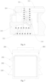
Fig. 6 is a partial enlarged view ofFig. 5 ; -
Fig. 7 is a side view corresponding to a state ofFig. 6 ; -
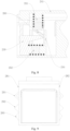
Fig. 8 is a partial enlarged view of another state ofFig. 5 ; and -
Fig. 9 is a side view corresponding to a state ofFig. 8 . -
- 100-track, 110-accommodating space, 120-first magnetic attraction piece, 130-fastener holder, 140-power supply conductive terminal, 150-signal conductive terminal, 160-insulation protection part,170-installation portion, 180-frame, 181-top wall, 182-sidewall,
- 200-adapter, 210-second magnetic attraction piece, 220-first fastener, 230-operating part, 240-housing, 241-top plate, 242-side plate, 243-opening, 244-baffle plate, 251-first spring piece, 252-second spring piece, 260-second fastener, 271-first end, 272-second end, 281-first side surface, 282-second side surface, 291-power supply spring piece, 292-signal spring piece,
- 300-light body.
- In order to make the purpose, technical solution and advantages of the present disclosure more clear, the technical solution of the present disclosure will be described clearly and completely with specific embodiments of the present disclosure and corresponding drawings. Obviously, the described embodiment is only a part of the embodiment of the present disclosure, not the whole embodiment. Based on the embodiments in the present disclosure, all other embodiments obtained by ordinary skilled in the field without creative labor belong to the scope of protection of the present disclosure.
- Hereinafter, the technical solution disclosed in each embodiment of the present application will be described in detail with reference to the accompanying drawings.
- As illustrated by
Figs. 1 to 9 , an embodiment of the present application provides atrack 100, anadapter 200 and a track light. - The track light includes the
adapter 200 and a power supply device or a power consumption device. The power supply device can be a driving power supply for converting a voltage of thetrack 100 into a voltage suitable for working, such as converting 220V alternating current into required direct current. The power consumption device can be alight body 300 for lighting, or the power consumption device can also be other device such as a sensor module or monitoring device to provide corresponding other functions. - The
track 100 is an installation member of the track light, and is used to install the track light to an installation foundation. The track light can be installed to thetrack 100 as required, and can slide in thetrack 100, and an installation position of the track light in thetrack 100 can be moved as required. - In a height direction, that is to say, in a direction perpendicular to the installation foundation, a side of the
track 100 is provided with aninstallation portion 170, and another side of thetrack 100 is provided with aframe 180. Theframe 180 encloses to form anaccommodating space 110 with an opening direction that is away from theinstallation portion 170. Theinstallation portion 170 is used to connect with the installation foundation, the installation foundation can be a ceiling or a wall. Theaccommodating space 110 is used for accommodating theadapter 200, and thetrack 100 is provided with a firstmagnetic attraction piece 120, the firstmagnetic attraction piece 120 is used for magnetically connecting with theadapter 200, and thetrack 100 is provided with afastener holder 130, thefastener holder 130 is used for engaging with theadapter 200. Theadapter 200 of the track light is accommodated in theaccommodating space 110. Theadapter 200 is provided with a second magnetic attraction piece 210 and afirst fastener 220. The second magnetic attraction piece 210 is used for magnetically connecting with the firstmagnetic attraction piece 120, and thefirst fastener 220 extends or retracts in theadapter 200, so that thefirst fastener 220 has an extended state and a retracted state. In the case that thefirst fastener 220 is in the extended state, thefirst fastener 220 is used to engage with thefastener holder 130, in the case that thefirst fastener 220 is in the retracted state, thefirst fastener 220 is used to separate from thefastener holder 130. - The magnetic connection between the first
magnetic attraction piece 120 and the second magnetic attraction piece 210 facilitates the installation of theadapter 200 in thetrack 100 and the sliding of theadapter 200 in thetrack 100, thus facilitating the installation and sliding of the track light in thetrack 100. One of the firstmagnetic attraction piece 120 and the second magnetic attraction piece 210 can be a permanent magnet and the other can be an iron sheet, and the permanent magnet and the iron sheet can be magnetically connected. Both the firstmagnetic attraction piece 120 and the second magnetic attraction piece 210 can be permanent magnets, and different magnetic poles of the two permanent magnets are oppositely arranged and can be magnetically connected. Of course, the firstmagnetic attraction piece 120 and the second magnetic attraction piece 210 can also be other types of magnetic attraction piece, which are not specifically limited in the embodiment of the present application. - In the extended state, the
first fastener 220 and thefastener holder 130 are engaged to realize an auxiliary support for theadapter 200. Even if the magnetic attraction between the firstmagnetic attraction piece 120 and the second magnetic attraction piece 210 disappears or a weight of the track light is relatively heavy, thefirst fastener 220 and thefastener holder 130 can also realize the connection between theadapter 200 and thetrack 100, which can prevent theadapter 200 from falling off thetrack 100, thus preventing the track light from falling off thetrack 100. - In the retracted state, the
first fastener 220 is separated from thefastener holder 130, and thefirst fastener 220 does not affect the installation of theadapter 200 into thetrack 100, nor does it affect the disassembly of theadapter 200 from thetrack 100. - Therefore, when it is needed to install the
adapter 200 into thetrack 100 or remove theadapter 200 from thetrack 100, thefirst fastener 220 can be in the retracted state to facilitate the installation of theadapter 200 into thetrack 100 or the removal of theadapter 200 from thetrack 100, thus facilitating the installation of the track light into thetrack 100. - After the
adapter 200 is installed in thetrack 100, the firstmagnetic attraction piece 120 and the second magnetic attraction piece 210 are magnetically connected to realize the connection between theadapter 200 and thetrack 100, in this case, thefirst fastener 220 is in the extended state, the engagement between thefirst fastener 220 and thefastener holder 130 also realizes the connection between theadapter 200 and thetrack 100. The engagement between thefirst fastener 220 and thefastener holder 130 can protect theadapter 200 and prevent theadapter 200 and the entire track light from falling off in the case that the magnetic attraction between the firstmagnetic attraction piece 120 and the second magnetic attraction piece 210 disappears or the weight of the track light is relatively heavy. - In the embodiment of the present application, the
track 100 is provided with a power supplyconductive terminal 140 arranged in theframe 180 and partially exposed in theaccommodating space 110, and the power supplyconductive terminal 140 extends along a length direction of thetrack 100, and the power supplyconductive terminal 140 is used for electrically connecting with theadapter 200. The power supplyconductive terminal 140 is used to supply power to theadapter 200, thereby supplying power to the track light. - Optionally, the
track 100 is provided with a signalconductive terminal 150 arranged in theframe 180 and partially exposed in theaccommodating space 110, and the signalconductive terminal 150 extends along the length direction of thetrack 100, and the signalconductive terminal 150 is used for electrically connecting with theadapter 200. The signalconductive terminal 150 is used for signal transmission with theadapter 200, thereby realizing signal transmission with the track light. - Specifically, an outer surface of the
adapter 200 is provided with a powersupply spring piece 291 and/or asignal spring piece 292, and the powersupply spring piece 291 is in contact with the power supplyconductive terminal 140, and thesignal spring piece 292 is in contact with the signalconductive terminal 150. The powersupply spring piece 291 and thesignal spring piece 292 may have certain elasticity. In the case that the powersupply spring piece 291 is in contact with the power supplyconductive terminal 140, the power supplyconductive terminal 140 exerts a certain force on the powersupply spring piece 291, and a restoring force of the powersupply spring piece 291 enables the powersupply spring piece 291 to be better contact with the power supplyconductive terminal 140, thus the reliable electrical connection can be realized. The position of theadapter 200 can also be moved under the condition of ensuring the electrical connection. In the case that thesignal spring piece 292 is in contact with the signalconductive terminal 150, the signalconductive terminal 150 exerts a certain force on thesignal spring piece 292, and a restoring force of thesignal spring piece 292 enables thesignal spring piece 292 to be better contact with the signalconductive terminal 150, thus the reliable signal connection can be realized. The position of theadapter 200 can also be moved under the condition of ensuring the signal connection. - The signal
conductive terminal 150 and thesignal spring piece 292 can be selectively arranged as required. - In the case that the track light needs to move on the
track 100, theadapter 200 can be pushed to slide on thetrack 100, and the powersupply spring piece 291 on the outer surface of theadapter 200 is always in contact with the power supplyconductive terminal 140 of thetrack 100, and thesignal spring piece 292 on the outer surface of theadapter 200 is always in contact with the signalconductive terminal 150 of thetrack 100, so that the position of theadapter 200 can be conveniently moved, and the power supply and signal transmission of theadapter 200 cannot be affected when the position of theadapter 200 is moved. - Further, the
track 100 is provided with aninsulation protection part 160 embedded in asidewall 182 of theframe 180, and theinsulation protection part 160 extends along the length direction of thetrack 100, and the power supplyconductive terminal 140 and/or the signalconductive terminal 150 are/is embedded in theinsulation protection part 160, and the power supplyconductive terminal 140 and/or the signalconductive terminal 150 are/is partially exposed in the accommodating space 10. Theinsulation protection part 160 can play an isolation role, and isolate thetrack 100 from the power supplyconductive terminal 140 and the signalconductive terminal 150, and thetrack 100 can be made of conductive material or insulating material, short circuit caused when thetrack 100 is made of conductive material can also be avoided. - The
frame 180 includes atop wall 181 and twosidewalls 182 perpendicular to thetop wall 181. Thetop wall 181 and the twosidewalls 182 perpendicular to thetop wall 181 enclose theaccommodating space 110. The first magnetic attraction piece is embedded in thetop wall 181 adjacent to theinstallation portion 170, and the power supply conductive terminals and/or signal conductive terminals are respectively located on the twosidewalls 182. A certain position of the twosidewalls 182 protrudes inward to form thefastener holder 130, or ends of the twosidewalls 182 may be bent inward to form thefastener holder 130. - The
adapter 200 is located in theaccommodating space 110 and is coupled with thetrack 100, and theadapter 200 is used for electrically connecting with power supply device or power consumption device, so as to realize that the power supply device or power consumption device obtains electricity from thetrack 100. - In the embodiment of the present application, the
adapter 200 is provided with the second magnetic attraction piece 210 at a top of theadapter 200 and thefirst fasteners 220 at two sides of theadapter 200, the second magnetic attraction piece 210 is used for magnetically connecting with the firstmagnetic attraction piece 120, and thefirst fasteners 220 can be extended or retracted from theadapter 200, so that thefirst fasteners 220 include the extended state and the retracted state, and in the case that thefirst fasteners 220 are in the extended state, thefirst fasteners 220 are used to engage with thefastener holders 130, and in the case that thefirst fasteners 220 are in the retracted state, thefirst fasteners 220 are used to separate from thefastener holders 130. - In the extended state, the
first fasteners 220 and thefastener holders 130 are engaged to realize the auxiliary support for theadapter 200. Even if the magnetic attraction between the firstmagnetic attraction piece 120 and the second magnetic attraction piece 210 disappears or the weight of the track light is relatively heavy, thefirst fasteners 220 and thefastener holders 130 can realize the connection between theadapter 200 and thetrack 100, which can prevent theadapter 200 from falling off thetrack 100, thus preventing the track light from falling off thetrack 100. - In the retracted state, the
first fasteners 220 are separated from thefastener holders 130, and thefirst fasteners 220 do not affect the installation of theadapter 200 into thetrack 100 or the removal of theadapter 200 from thetrack 100, thus facilitating the installation of the track light into thetrack 100 or the removal of the track light from thetrack 100. - Therefore, when it is needed to install the
adapter 200 into thetrack 100 or remove theadapter 200 from thetrack 100, thefirst fasteners 220 can be in the retracted state to facilitate the installation of theadapter 200 into thetrack 100 and the installation of the track light into thetrack 100, or to facilitate the removal of theadapter 200 from thetrack 100 and the removal of the track light from thetrack 100. - After the
adapter 200 is installed in thetrack 100, the firstmagnetic attraction piece 120 and the second magnetic attraction piece 210 are magnetically connected to realize the connection between theadapter 200 and thetrack 100, in this case, thefirst fasteners 220 are in the extended state, the engagement between thefirst fasteners 220 and thefastener holders 130 also realize the connection between theadapter 200 and thetrack 100. The engagement between thefirst fasteners 220 and thefastener holders 130 can protect theadapter 200 and prevent theadapter 200 from falling off in the case that the magnetic attraction between the firstmagnetic attraction piece 120 and the second magnetic attraction piece 210 disappears or the weight of the track light is relatively heavy, so as to prevent the track light from falling off. - Therefore, the mechanical connection between the
adapter 200 and thetrack 100 can be realized through the above structure, and theadapter 200 and thetrack 100 also need to be electrically connected. - Specifically, two sides of the
adapter 200 are provided with powersupply spring pieces 291, and thetrack 100 is provided with power supplyconductive terminals 140 which are arranged in theframe 180 and partially exposed in theaccommodating space 110, and the power supplyconductive terminals 140 extend along the length direction of thetrack 100, and the powersupply spring pieces 291 are configured to be in contact with the power supplyconductive terminals 140. Through this structure, the electrical connection between theadapter 200 and thetrack 100 can be realized. - Optionally, two sides of the
adapter 200 are provided withsignal spring pieces 292, and thetrack 100 is provided with signalconductive terminals 150 which are arranged in theframe 180 and partially exposed in theaccommodating space 110, and the signalconductive terminals 150 extend along the length direction of thetrack 100, and thesignal spring pieces 292 is configured to be in contact with the signalconductive terminals 150. Through this structure, the signal connection between theadapter 200 and thetrack 100 can be realized. The signalconductive terminals 150 and thesignal spring pieces 292 can be selectively arranged as required. - The power
supply spring pieces 291 and thesignal spring pieces 292 may have certain elasticity. In the case that the powersupply spring pieces 291 are in contact with the power supplyconductive terminals 140, the power supplyconductive terminals 140 exert the certain force on the powersupply spring pieces 291, and the restoring force of the powersupply spring pieces 291 enables the powersupply spring pieces 291 to be better contact with the power supplyconductive terminals 140, thus the reliable electrical connection can be realized. The position of theadapter 200 can also be moved under the condition of ensuring the electrical connection. In the case that thesignal spring pieces 292 are in contact with the signalconductive terminals 150, the signalconductive terminals 150 exert the certain force on thesignal spring pieces 292, and the restoring force of thesignal spring pieces 292 enables thesignal spring pieces 292 to be better contact with the signalconductive terminals 150, thus the reliable signal connection can be realized. The position of theadapter 200 can also be moved under the condition of ensuring the signal connection. - In the case that the track light needs to move on the
track 100, theadapter 200 can be pushed to slide on thetrack 100, and the powersupply spring pieces 291 on the outer surface of theadapter 200 are always in contact with the power supplyconductive terminals 140 of thetrack 100, and thesignal spring pieces 292 on the outer surface of theadapter 200 are always in contact with the signalconductive terminals 150 of thetrack 100, so that the position of theadapter 200 can be conveniently moved, and the power supply and signal transmission of theadapter 200 cannot be affected when the position of theadapter 200 is moved. - In the embodiment of the present application, a switching between the extended state and the retracted state of the
first fastener 220 can be manually controlled or automatically controlled by a control device, which is not specifically limited in the embodiment of the present application. - Optionally, the
adapter 200 is further provided with anoperating part 230, the operatingpart 230 is cooperated with thefirst fastener 220, and theoperating part 230 is used for driving thefirst fastener 220 to switch between the extended state and the retracted state. That is to say, thefirst fastener 220 can be driven to switch between the extended state and the retracted state through the operatingpart 230, so as to drive thefirst fastener 220 to the extended state or to the retracted state when needed. - In the embodiment of the present application, the
adapter 200 includes ahousing 240, and thefirst fastener 220 and theoperating part 230 are arranged on thehousing 240. Thefirst fastener 220, the operatingpart 230 and theadapter 200 are integrated, and then are installed to thetrack 100 as an integral component, which is convenient for assembly. - The
housing 240 includes atop plate 241 and aside plate 242. The second magnetic attraction piece 210 can be arranged on thetop plate 241. Thetop plate 241 is connected with the firstmagnetic attraction piece 120 of thetrack 100 through the second magnetic attraction piece 210. Theside plate 242 is provided with anopening 243. In the case that thefirst fastener 220 is in the extended state, thefirst fastener 220 extends out of theopening 243. In the case that thefirst fastener 220 is in the retracted state, thefirst fastener 220 retracts into theopening 243. - After the
first fastener 220 extends out of theopening 243, a part of thefirst fastener 220 extending out of theopening 243 can be engaged with thefastener holder 130, so that theadapter 200 can be engaged with thetrack 100. After thefirst fastener 220 retracts into theopening 243, thefirst fastener 220 is separated from thefastener holder 130, and theadapter 200 is disconnected from thetrack 100, which is convenient for installing theadapter 200 into thetrack 100 or removing theadapter 200 from thetrack 100. - In the embodiment of the present application, the
first fastener 220 is connected with thetop plate 241 through afirst spring piece 251, and theoperating part 230 is connected with theside plate 242 through asecond spring piece 252. A surface of thefirst fastener 220 that engaged with the operatingpart 230 is an inclined surface, and a surface of thefirst fastener 220 opposite to theside plate 242 is an inclined surface. - In the case that the operating
part 230 moves in a first direction, the operatingpart 230 drives thefirst fastener 220 to move in a direction towards thetop plate 241, and in the case that thefirst fastener 220 moves in the direction towards thetop plate 241, theside plate 242 presses thefirst fastener 220 to retract into theopening 243. In the case that the operatingpart 230 moves in a second direction, thefirst spring piece 251 drives thefirst fastener 220 to move in a direction away from thetop plate 241; in the case that thefirst fastener 220 moves in the direction away from thetop plate 241, thefirst spring piece 251 drives thefirst fastener 220 to extend out of theopening 243, and the second direction is opposite to the first direction. - In the case that the
adapter 200 needs to be installed on thetrack 100, the operatingpart 230 is pressed in the first direction, so that thesecond spring piece 252 is compressed, and theoperating part 230 is in contact with thefirst fastener 220, because the surface of thefirst fastener 220 cooperated with the operatingpart 230 is the inclined surface, in the case that the operatingpart 230 moves in the first direction, the operatingpart 230 drives thefirst fastener 220 to move towards thetop plate 241. Thefirst spring piece 251 is compressed. In the case that thefirst fastener 220 moves towards thetop plate 241, theside plate 242 presses thefirst fastener 220 to retract into theopening 243, and thefirst spring piece 251 is compressed. In this case, theadapter 200 can be installed on thetrack 100, and theadapter 200 and thetrack 100 can be magnetically connected by the firstmagnetic attraction piece 120 and the second magnetic attraction piece 210. - Then, the operating part is released, and the
operating part 230 moves in the second direction due to the restoring force of thesecond spring piece 252, and thefirst fastener 220 moves away from thetop plate 241 due to the restoring force of thefirst spring piece 251. In the case that thefirst fastener 220 moves in a direction away from thetop plate 241, thefirst spring piece 251 further drives thefirst fastener 220 to extend out of theopening 243, and the second direction is opposite to the first direction. - The first direction may be a direction that an end of the
adapter 200 where the operatingpart 230 is located points to a center of theadapter 200 along a length direction of theadapter 200, and the second direction may be a direction that the center of theadapter 200 points to the end of theadapter 200 where the operatingpart 230 is located along the length direction of theadapter 200. Thefirst spring piece 251 and thesecond spring piece 252 may be springs. - In the embodiment of the present application, the
side plate 242 is provided with abaffle plate 244, and thebaffle plate 244 is cooperated with thefirst fastener 220, and thebaffle plate 244 is used for preventing thefirst fastener 220 from moving in the first direction in the case that the operatingpart 230 moves in the first direction. That is to say, thebaffle plate 244 and theoperating part 230 are oppositely arranged, in the case that the operatingpart 230 moves in the first direction, the operatingpart 230 is cooperated with the inclined surface of thefirst fastener 220, but thebaffle plate 244 can prevent thefirst fastener 220 from moving in the first direction, so thefirst fastener 220 can only move in the direction close to thetop plate 241 in this case. On the one hand, thebaffle plate 244 is cooperated with thefirst fastener 220, and thebaffle plate 244 can prevent thefirst fastener 220 from moving in the first direction, so that thefirst fastener 220 can move in the direction close to thetop plate 241 under the drive of the operatingpart 230; on the other hand, thebaffle plate 244 can further guide thefirst fastener 220 to move in a direction of thebaffle plate 244 in the case that thefirst fastener 220 is driven by the operatingpart 230, thus playing a guiding role for thefirst fastener 220. - In the embodiment of the present application, optionally, the
adapter 200 is further provided with asecond fastener 260, thesecond fastener 260 is engaged with thefastener holder 130 and is a spring fastener, and can be separated from thefastener holder 130 in the case that an external force on thesecond fastener 260 reaches a preset threshold. - The
second fastener 260 engages with thefastener holder 130 and also supports theadapter 200. Together with thefirst fastener 220, thesecond fastener 260 supports theadapter 200. In the case that the magnetic attraction between the firstmagnetic attraction piece 120 and the second magnetic attraction piece 210 disappears or the weight of the track light is relatively heavy, thesecond fastener 260 engages with thefastener holder 130 to prevent theadapter 200 from falling off thetrack 100, thereby preventing the track light from falling off thetrack 100. - If the
adapter 200 needs to be removed from thetrack 100, because thesecond fastener 260 is a spring fastener, a large force is applied to theadapter 200, in the case that the external force on thesecond fastener 260 reaches the preset threshold, thesecond fastener 260 can be separated from thefastener holder 130, and in this case, theadapter 200 can also be separated from thetrack 100. Therefore, thesecond fastener 260 can not only achieve the function of supporting, but also facilitate the separation of theadapter 200 from thetrack 100. - In the embodiment of the present application, the
adapter 200 includes afirst end 271 and asecond end 272, thefirst end 271 and thesecond end 272 are arranged oppositely, thefirst fastener 220 is arranged at thefirst end 271, and thesecond fastener 260 is arranged at thesecond end 272. That is to say, thefirst fastener 220 is arranged at an end and thesecond fastener 260 is arranged at another end. Thefirst fastener 220 is engaged with thefastener holder 130, which makes the connection between theadapter 200 and thetrack 100 more reliable. However, an installation structure of thefirst fastener 220 is more complicated, and an installation structure of thesecond fastener 260 is relatively simple, which can also play an auxiliary support role to some extent. - In the embodiment of the present application, the
adapter 200 includes afirst side surface 281 and asecond side surface 282, which are oppositely arranged, and both thefirst side surface 281 and thesecond side surface 282 are provided with thefirst fasteners 220. That is to say, both thefirst side surface 281 and thesecond side surface 282 of theadapter 200 are provided with thefirst fasteners 220, so that thefirst fasteners 220 can reliably support theadapter 200 on two side surfaces. - Further, both the
first side surface 281 and thesecond side surface 282 are provided with thesecond fasteners 260. That is to say, both thefirst side surface 281 and thesecond side surface 282 of theadapter 200 are provided with thesecond fasteners 260, so that thesecond fasteners 260 can reliably support theadapter 200 on two side surfaces. - Optionally, the
first end 271, thefirst side surface 281 and thesecond side surface 282 of theadapter 200 are all provided with thefirst fasteners 220, thesecond end 272, thefirst side surface 281 and thesecond side surface 282 of theadapter 200 of theadapter 200 are all provided with thesecond fasteners 260, so that theadapter 200 includes at least four auxiliary support points, even if the magnetic attraction of the firstmagnetic attraction piece 120 and the second magnetic attraction piece 210 disappears, or the weight of the track light is relatively heavy, the four auxiliary support points can uniformly support theadapter 200. - In addition, in the embodiment of the present application, the
first fastener 220 is connected with thetop plate 241 through thefirst spring piece 251, even if the magnetic attraction of the firstmagnetic attraction piece 120 and the second magnetic attraction piece 210 disappears or the weight of theadapter 200 is so heavier that the firstmagnetic attraction piece 120 and the second magnetic attraction piece 210 are separated, that is to say, even if thetop plate 241 of theadapter 200 is separated from thetrack 100, thefirst fastener 220 can support theadapter 200 by engaging with thefastener holder 130, and in this case, thefirst fastener 220 is connected with thetop plate 241 through thefirst spring piece 251, thefirst spring piece 251 can play a buffering role for theadapter 200 and prevent internal structural members of theadapter 200 from being impacted. - In the embodiment of the present application, the track light includes the
adapter 200, which is adapted to thetrack 100. The track light further includes power supply device or power consumption device. The power supply device can be a driving power supply for converting a voltage of thetrack 100 into a voltage suitable for working, for example, converting 220V alternating current into a required direct current. The power consumption device can be alight body 300 for lighting, or the power consumption device can also be other device such as sensor module or monitoring device to provide corresponding others functions. The power supply device or power consumption device is arranged in theadapter 200, and the power supply device or power consumption device is electrically connected with theadapter 200. - The power consumption device can be connected with the
adapter 200 and directly supplied with power by thetrack 100 through theadapter 200, or the power consumption device can be connected with theadapter 200, and the voltage of the track is converted by the above-mentioned power supply device, and then power is supplied to the power consumption device. - Specifically, the power supply device may be provided inside the
adapter 200, for example, inside thehousing 240 of theadapter 200. Thelight body 300 can be below theaccommodating space 110. Thelight body 300 can be directly connected with theadapter 200, and both thelight body 300 and theadapter 200 can be located in theaccommodating space 110, and a light-exiting surface of thelight body 300 faces the opening of theaccommodating space 110, or a part of thelight body 300 extends out of theaccommodating space 110 through the opening to realize illumination. In this case, the track light can be a linear light, a flat light, etc. Alternatively, thelight body 300 can be connected with theadapter 200 through a connection rod, theadapter 200 is located in theaccommodating space 110, and thelight body 300 is located outside theaccommodating space 110 to realize illumination. In this case, the track light can be a spotlight, etc. - The first
magnetic attraction piece 120 of thetrack 100 and the second magnetic attraction piece 210 of theadapter 200 are magnetically connected, which facilitates the installation of theadapter 200 in thetrack 100 and the sliding of theadapter 200 in thetrack 100, thus facilitating the installation and sliding of the track light in thetrack 100. In the extended state, thefirst fastener 220 and thefastener holder 130 are engaged, so that even if the magnetic attraction between the firstmagnetic attraction piece 120 and the second magnetic attraction piece 210 disappears, thefirst fastener 220 and thefastener holder 130 can realize the connection between theadapter 200 and thetrack 100, and prevent theadapter 200 from falling off thetrack 100, thereby preventing the track light from falling off thetrack 100; in the retracted state, thefirst fastener 220 is separated from thefastener holder 130, and thefirst fastener 220 does not affect the installation of theadapter 200 into thetrack 100, nor does it affect the removal of theadapter 200 from thetrack 100, thus facilitating the installation and removal of the track light. - In the case that the track light needs to be installed in the
track 100 or removed from thetrack 100, thefirst fastener 220 is in the retracted state. After theadapter 200 is installed in thetrack 100, the firstmagnetic attraction piece 120 and the second magnetic attraction piece 210 are magnetically connected, and thefirst fastener 220 is in the extended state to protect the track light and prevent the track light from falling off. - Moreover, the power
supply spring pieces 291 are arranged on two sides of theadapter 200, and thetrack 100 is provided with the power supplyconductive terminals 140 which are arranged in theframe 180 and partially exposed in theaccommodating space 110, and the power supplyconductive terminals 140 extend along the length direction of thetrack 100, and the powersupply spring pieces 291 are configured to be contact with the power supplyconductive terminals 140. Through this structure, the electrical connection between theadapter 200 and thetrack 100 can be realized. - Optionally, the
signal spring pieces 292 are arranged on two sides of theadapter 200, and thetrack 100 is provided with the signalconductive terminals 150 which are arranged in theframe 180 and partially exposed in theaccommodating space 110, and the signalconductive terminals 150 extend along the length direction of thetrack 100, and thesignal spring pieces 292 are configured to be contact with the signalconductive terminals 150. Through this structure, the signal connection between theadapter 200 and thetrack 100 can be realized. - The
first fastener 220 and thesecond fastener 260 assist in supporting theadapter 200. Even if the firstmagnetic attraction piece 120 and the second magnetic attraction piece 210 are separated, that is to say, even if thetop plate 241 of theadapter 200 is separated from thetrack 100, thefirst fastener 220 is engaged with thefastener holder 130 and thesecond fastener 260 is engaged with thefastener holder 130, theadapter 200 can be supported, and in this case, thefirst fastener 220 is connected with thetop plate 241 through thefirst spring piece 251, thefirst spring piece 251 can play a buffering role for theadapter 200 and prevent internal structural members of theadapter 200 from being impacted. - The above embodiment of the present invention focuses on the differences among the embodiments, and the different optimization features among the embodiments can be combined to form a better embodiment as long as they are not contradictory. Considering the brevity of the writing, the repeated portions are omitted herein.
- The above is only an example of the present disclosure, and is not used to limit the present disclosure. Various modifications and variations will occur to those skilled in the art. Any modification, equivalent substitution, improvement, etc. made within the spirit and principle of the present disclosure should be included in the scope of the claims of the present disclosure.
Claims (12)
- A track (100), wherein, in a height direction, a side of the track (100) is provided with an installation portion (170), and another side of the track (100) is provided with a frame (180), the frame (180) encloses to form an accommodating space (110) with an opening direction that is away from the installation portion (170), the installation portion (170) is used to connect with an installation foundation, the accommodating space (110) is used for accommodating an adapter (200), and the track (100) is provided with a first magnetic attraction piece (120), the first magnetic attraction piece (120) is used for magnetically connecting with the adapter (200), and the track (100) is provided with a fastener holder (130), the fastener holder (130) is used for engaging with the adapter (200).
- The track (100) according to claim 1, wherein the track (100) is provided with a power supply conductive terminal (140) and/or a signal conductive terminal (150) arranged in the frame (180) and partially exposed in the accommodating space (110), and the power supply conductive terminal (140) and/or the signal conductive terminal (150) extend/extends along a length direction of the track (100), and the power supply conductive terminal (140) and the signal conductive terminal (150) are used for electrically connecting with the adapter (200).
- The track (100) according to claim 2, wherein the track (100) is provided with an insulation protection part (160) embedded in a sidewall (182) of the frame (180), and the insulation protection part (160) extends along the length direction of the track (100), and the power supply conductive terminal (140) and/or the signal conductive terminal (150) are/is embedded in the insulation protection part (160).
- The track (100) according to claim 2, wherein the frame (180) comprises a top wall (181) and two sidewalls (182) perpendicular to the top wall (181), the first magnetic attraction piece is embedded in the top wall (181) adjacent to the installation portion (170), and the power supply conductive terminals and/or signal conductive terminals are respectively located on the two sidewalls (182).
- An adapter (200), used for electrically connecting with a power supply device or a power consumption device and coupled in the track (100) according to any one of claims 1-4, so as to realize that the power supply device or the power consumption device obtains electricity from the track (100), wherein the adapter (200) is provided with a second magnetic attraction piece (210) at a top of the adapter (200) and first fasteners (220) at two sides of the adapter (200), the second magnetic attraction piece (210) is used for magnetically connecting with the first magnetic attraction piece (120), the first fasteners (220) comprise an extended state and a retracted state, and in a case that the first fasteners (220) are in the extended state, the first fasteners (220) are used to engage with the fastener holder (130), and in a case that the first fasteners (220) are in the retracted state, the first fasteners (220) are used to separate from the fastener holder (130).
- The adapter (200) according to claim 5, wherein two sides of the adapter (200) are provided with power supply spring pieces (291) and/or signal spring pieces (292), and the track (100) is provided with power supply conductive terminals (140) and/or signal conductive terminals (150) which are arranged in the frame (180) and partially exposed in the accommodating space (110), and the power supply conductive terminals (140) and/or signal conductive terminals (150) both extend along a length direction of the track (100), the power supply spring pieces (291) are configured to be in contact with the power supply conductive terminals (140), and the signal spring pieces (292) are configured to be in contact with the signal conductive terminals (150).
- The adapter (200) according to claim 5, wherein the adapter (200) is further provided with an operating part (230), the operating part (230) is configured to be cooperated with the first fasteners (220), and the operating part (230) is used for driving the first fasteners (220) to switch between the extended state and the retracted state.
- The adapter (200) according to claim 7, wherein the adapter (200) comprises a housing (240), and the first fasteners (220) and the operating part (230) are arranged on the housing (240), the housing (240) comprises a top plate (241) and a side plate (242), the side plate (242) is provided with an opening (243), in the case that the first fasteners (220) are in the extended state, the first fasteners (220) extend out of the opening (243), in the case that the first fasteners (220) is in the retracted state, the first fastener (220) retract into the opening (243).
- The adapter (200) according to claim 8, wherein the first fasteners (220) are connected with the top plate (241) through a first spring piece (251), and the operating part (230) is connected with the side plate (242) through a second spring piece (252), a surface of the first fasteners (220) that engaged with the operating part (230) is an inclined surface, and a surface of the first fasteners (220) opposite to the side plate (242) is an inclined surface,in a case that the operating part (230) moves in a first direction, the operating part (230) drives the first fasteners (220) to move in a direction towards the top plate (241), and in a case that the first fastener (220) moves in a direction towards the top plate (241), the side plate (242) presses the first fasteners (220) to retract into the opening (243),in a case that the operating part (230) moves in a second direction, the first spring piece (251) drives the first fasteners (220) to move in a direction away from the top plate (241), and in a case that the first fastener (220) moves in a direction away from the top plate (241), the first spring piece (251) drives the first fasteners (220) to extend out of the opening (243), and the second direction is opposite to the first direction.
- The adapter (200) according to claim 9, wherein the side plate (242) is provided with a baffle plate (244), and the baffle plate (244) is cooperated with the first fasteners (220), and the baffle plate (244) is used for preventing the first fasteners (220) from moving in the first direction in the case that the operating part (230) moves in the first direction.
- The adapter (200) according to claim 5, wherein the adapter (200) is further provided with a second fastener (260), the second fastener (260) is engaged with the fastener holder (130) and is a spring fastener, and is able to be separated from the fastener holder (130) in a case that an external force on the second fastener (260) reaches a preset threshold,
the adapter (200) comprises a first end (271) and a second end (272), the first end (271) and the second end (272) are arranged oppositely, the first fasteners (220) are arranged at the first end (271), and the second fastener (260) is arranged at the second end (272). - A track light, comprising the adapter (200) according to any one of claims 5-11, which is adapted to the track (100) according to any one of claims 1-4, the track light further comprises a power supply device or a power consumption device, the power supply device or the power consumption device is arranged in the adapter (200), and the power supply device or the power consumption device is electrically connected with the adapter (200),
the second magnetic attraction piece (210) is used for magnetically connecting with the first magnetic attraction piece (120), the first fasteners (220) comprises an extended state and a retracted state, and in a case that the first fasteners (220) is in the extended state, the first fasteners (220) are used to engage with the fastener holder (130), and in a case that the first fasteners (220) are in the retracted state, the first fastener (220) is used to separate from the fastener holder (130).
Applications Claiming Priority (3)
| Application Number | Priority Date | Filing Date | Title |
|---|---|---|---|
| CN202111661282.6A CN114151748B (en) | 2021-12-30 | 2021-12-30 | Tracks, adapters and track lights |
| CN202123436513.1U CN216383846U (en) | 2021-12-30 | 2021-12-30 | Track, adapter and guide rail lamp |
| PCT/CN2022/139135 WO2023125025A1 (en) | 2021-12-30 | 2022-12-14 | Track, adapter and track lamp |
Publications (2)
| Publication Number | Publication Date |
|---|---|
| EP4459175A1 true EP4459175A1 (en) | 2024-11-06 |
| EP4459175A4 EP4459175A4 (en) | 2025-04-09 |
Family
ID=86997669
Family Applications (1)
| Application Number | Title | Priority Date | Filing Date |
|---|---|---|---|
| EP22914280.7A Pending EP4459175A4 (en) | 2021-12-30 | 2022-12-14 | RAIL, ADAPTER AND TRACK LAMP |
Country Status (3)
| Country | Link |
|---|---|
| US (1) | US20240353077A1 (en) |
| EP (1) | EP4459175A4 (en) |
| WO (1) | WO2023125025A1 (en) |
Families Citing this family (2)
| Publication number | Priority date | Publication date | Assignee | Title |
|---|---|---|---|---|
| CN116709698B (en) * | 2023-08-09 | 2023-10-03 | 深圳市星火光电科技有限公司 | Power module convenient for track lamp plugging |
| CN119042583B (en) * | 2024-10-26 | 2025-01-17 | 温州市登来特照明有限公司 | A kind of intelligent controlled manual double-adjustable multi-directional track light |
Family Cites Families (8)
| Publication number | Priority date | Publication date | Assignee | Title |
|---|---|---|---|---|
| CN208919846U (en) * | 2018-10-19 | 2019-05-31 | 广东艾罗照明科技股份有限公司 | A kind of magnetic track lamp |
| CN208951792U (en) * | 2018-10-26 | 2019-06-07 | 佛山市凯昌灯饰电器有限公司 | A kind of magnetic-type track lamp |
| CN210891541U (en) * | 2019-10-12 | 2020-06-30 | 佛山工匠光健康照明科技有限公司 | Magnetic lamp rail for guide lamp |
| CN111022979A (en) * | 2020-01-02 | 2020-04-17 | 广东凯西欧光健康有限公司 | Guide rail lamp |
| CN212408585U (en) * | 2020-06-29 | 2021-01-26 | 曹醒强 | Guide rail lamp connector and guide rail lamp connecting assembly comprising same |
| CN213299728U (en) * | 2020-08-17 | 2021-05-28 | 佛山市新辉帅照明电器有限公司 | Guide rail lamp convenient to dismouting |
| CN214619230U (en) * | 2021-05-24 | 2021-11-05 | 黎兆湛 | Rail lamp power source head with stepped magnet |
| CN114151748B (en) * | 2021-12-30 | 2025-06-27 | 欧普照明股份有限公司 | Tracks, adapters and track lights |
-
2022
- 2022-12-14 EP EP22914280.7A patent/EP4459175A4/en active Pending
- 2022-12-14 WO PCT/CN2022/139135 patent/WO2023125025A1/en not_active Ceased
-
2024
- 2024-06-30 US US18/759,906 patent/US20240353077A1/en active Pending
Also Published As
| Publication number | Publication date |
|---|---|
| EP4459175A4 (en) | 2025-04-09 |
| US20240353077A1 (en) | 2024-10-24 |
| WO2023125025A1 (en) | 2023-07-06 |
Similar Documents
| Publication | Publication Date | Title |
|---|---|---|
| US20240353077A1 (en) | Track, adapter and track light | |
| CN114151748B (en) | Tracks, adapters and track lights | |
| CN114284783B (en) | Track adapters, tracks and electrical systems | |
| CN107588371B (en) | Integrated lifting ceiling lamp capable of being powered on and powered off timely | |
| EP4459808A1 (en) | Track adapter, track and electrical system | |
| CN110274184B (en) | High-safety spliced line lamp | |
| CN114389088B (en) | Track adapters, tracks and electrical systems | |
| US8646937B2 (en) | Switch panel illumination structure | |
| CN216383846U (en) | Track, adapter and guide rail lamp | |
| CN114508723A (en) | Lighting device of intelligent installation engineering of wisdom city building | |
| CN208061973U (en) | Contactor auxiliary circuit connection structure | |
| CN215061873U (en) | Contact track lighting lamp | |
| CN109616386B (en) | electric breaker | |
| KR102235275B1 (en) | Rail and connector for led lighting | |
| CN210511534U (en) | Fixing structure of light source electric appliance | |
| CN216672000U (en) | Track adapter, track and electrical system | |
| CN215184909U (en) | Adapters and Rail Sockets | |
| CN217004200U (en) | Embedded lamp strip of absorption LED is inhaled with convenient dismantlement magnetism to furniture | |
| CN114419910A (en) | Traffic signal lamp of emergent automatic switch-over circuit | |
| CN209084717U (en) | A kind of protection against electric shock mechanism of fluorescent tube | |
| CN220688990U (en) | Power supply box | |
| CN220021912U (en) | Safe electric shock prevention power distribution control device | |
| CN217008958U (en) | Fire-cut-off limiter | |
| CN217843636U (en) | Lamp bracket, detachable module lamp and magnetic rail lamp system | |
| CN221530965U (en) | Be used for automatic excessive pressure overcurrent protection PCBA board of bluetooth headset |
Legal Events
| Date | Code | Title | Description |
|---|---|---|---|
| STAA | Information on the status of an ep patent application or granted ep patent |
Free format text: STATUS: THE INTERNATIONAL PUBLICATION HAS BEEN MADE |
|
| PUAI | Public reference made under article 153(3) epc to a published international application that has entered the european phase |
Free format text: ORIGINAL CODE: 0009012 |
|
| STAA | Information on the status of an ep patent application or granted ep patent |
Free format text: STATUS: REQUEST FOR EXAMINATION WAS MADE |
|
| 17P | Request for examination filed |
Effective date: 20240730 |
|
| AK | Designated contracting states |
Kind code of ref document: A1 Designated state(s): AL AT BE BG CH CY CZ DE DK EE ES FI FR GB GR HR HU IE IS IT LI LT LU LV MC ME MK MT NL NO PL PT RO RS SE SI SK SM TR |
|
| REG | Reference to a national code |
Ref country code: DE Ref legal event code: R079 Free format text: PREVIOUS MAIN CLASS: F21S0008000000 Ipc: F21V0021350000 |
|
| A4 | Supplementary search report drawn up and despatched |
Effective date: 20250310 |
|
| DAV | Request for validation of the european patent (deleted) | ||
| DAX | Request for extension of the european patent (deleted) | ||
| RIC1 | Information provided on ipc code assigned before grant |
Ipc: H01R 25/14 20060101ALN20250304BHEP Ipc: H01R 13/62 20060101ALN20250304BHEP Ipc: F21S 4/28 20160101ALI20250304BHEP Ipc: F21V 23/06 20060101ALI20250304BHEP Ipc: F21V 21/096 20060101ALI20250304BHEP Ipc: F21V 21/35 20060101AFI20250304BHEP |