EP4459147A1 - A bearing ring, a bearing, a wind turbine and method of manufacturing a bearing ring - Google Patents
A bearing ring, a bearing, a wind turbine and method of manufacturing a bearing ring Download PDFInfo
- Publication number
- EP4459147A1 EP4459147A1 EP23171565.7A EP23171565A EP4459147A1 EP 4459147 A1 EP4459147 A1 EP 4459147A1 EP 23171565 A EP23171565 A EP 23171565A EP 4459147 A1 EP4459147 A1 EP 4459147A1
- Authority
- EP
- European Patent Office
- Prior art keywords
- hardening
- bearing
- bearing ring
- raceway
- bearings
- Prior art date
- Legal status (The legal status is an assumption and is not a legal conclusion. Google has not performed a legal analysis and makes no representation as to the accuracy of the status listed.)
- Pending
Links
Images

Classifications
-
- F—MECHANICAL ENGINEERING; LIGHTING; HEATING; WEAPONS; BLASTING
- F16—ENGINEERING ELEMENTS AND UNITS; GENERAL MEASURES FOR PRODUCING AND MAINTAINING EFFECTIVE FUNCTIONING OF MACHINES OR INSTALLATIONS; THERMAL INSULATION IN GENERAL
- F16C—SHAFTS; FLEXIBLE SHAFTS; ELEMENTS OR CRANKSHAFT MECHANISMS; ROTARY BODIES OTHER THAN GEARING ELEMENTS; BEARINGS
- F16C33/00—Parts of bearings; Special methods for making bearings or parts thereof
- F16C33/30—Parts of ball or roller bearings
- F16C33/58—Raceways; Race rings
- F16C33/583—Details of specific parts of races
- F16C33/585—Details of specific parts of races of raceways, e.g. ribs to guide the rollers
-
- C—CHEMISTRY; METALLURGY
- C21—METALLURGY OF IRON
- C21D—MODIFYING THE PHYSICAL STRUCTURE OF FERROUS METALS; GENERAL DEVICES FOR HEAT TREATMENT OF FERROUS OR NON-FERROUS METALS OR ALLOYS; MAKING METAL MALLEABLE, e.g. BY DECARBURISATION OR TEMPERING
- C21D1/00—General methods or devices for heat treatment, e.g. annealing, hardening, quenching or tempering
- C21D1/06—Surface hardening
- C21D1/09—Surface hardening by direct application of electrical or wave energy; by particle radiation
- C21D1/10—Surface hardening by direct application of electrical or wave energy; by particle radiation by electric induction
-
- C—CHEMISTRY; METALLURGY
- C21—METALLURGY OF IRON
- C21D—MODIFYING THE PHYSICAL STRUCTURE OF FERROUS METALS; GENERAL DEVICES FOR HEAT TREATMENT OF FERROUS OR NON-FERROUS METALS OR ALLOYS; MAKING METAL MALLEABLE, e.g. BY DECARBURISATION OR TEMPERING
- C21D9/00—Heat treatment, e.g. annealing, hardening, quenching or tempering, adapted for particular articles; Furnaces therefor
- C21D9/40—Heat treatment, e.g. annealing, hardening, quenching or tempering, adapted for particular articles; Furnaces therefor for rings; for bearing races
-
- F—MECHANICAL ENGINEERING; LIGHTING; HEATING; WEAPONS; BLASTING
- F16—ENGINEERING ELEMENTS AND UNITS; GENERAL MEASURES FOR PRODUCING AND MAINTAINING EFFECTIVE FUNCTIONING OF MACHINES OR INSTALLATIONS; THERMAL INSULATION IN GENERAL
- F16C—SHAFTS; FLEXIBLE SHAFTS; ELEMENTS OR CRANKSHAFT MECHANISMS; ROTARY BODIES OTHER THAN GEARING ELEMENTS; BEARINGS
- F16C33/00—Parts of bearings; Special methods for making bearings or parts thereof
- F16C33/30—Parts of ball or roller bearings
- F16C33/58—Raceways; Race rings
- F16C33/64—Special methods of manufacture
-
- F—MECHANICAL ENGINEERING; LIGHTING; HEATING; WEAPONS; BLASTING
- F16—ENGINEERING ELEMENTS AND UNITS; GENERAL MEASURES FOR PRODUCING AND MAINTAINING EFFECTIVE FUNCTIONING OF MACHINES OR INSTALLATIONS; THERMAL INSULATION IN GENERAL
- F16C—SHAFTS; FLEXIBLE SHAFTS; ELEMENTS OR CRANKSHAFT MECHANISMS; ROTARY BODIES OTHER THAN GEARING ELEMENTS; BEARINGS
- F16C2223/00—Surface treatments; Hardening; Coating
-
- F—MECHANICAL ENGINEERING; LIGHTING; HEATING; WEAPONS; BLASTING
- F16—ENGINEERING ELEMENTS AND UNITS; GENERAL MEASURES FOR PRODUCING AND MAINTAINING EFFECTIVE FUNCTIONING OF MACHINES OR INSTALLATIONS; THERMAL INSULATION IN GENERAL
- F16C—SHAFTS; FLEXIBLE SHAFTS; ELEMENTS OR CRANKSHAFT MECHANISMS; ROTARY BODIES OTHER THAN GEARING ELEMENTS; BEARINGS
- F16C2223/00—Surface treatments; Hardening; Coating
- F16C2223/10—Hardening, e.g. carburizing, carbo-nitriding
- F16C2223/18—Hardening, e.g. carburizing, carbo-nitriding with induction hardening
-
- F—MECHANICAL ENGINEERING; LIGHTING; HEATING; WEAPONS; BLASTING
- F16—ENGINEERING ELEMENTS AND UNITS; GENERAL MEASURES FOR PRODUCING AND MAINTAINING EFFECTIVE FUNCTIONING OF MACHINES OR INSTALLATIONS; THERMAL INSULATION IN GENERAL
- F16C—SHAFTS; FLEXIBLE SHAFTS; ELEMENTS OR CRANKSHAFT MECHANISMS; ROTARY BODIES OTHER THAN GEARING ELEMENTS; BEARINGS
- F16C2300/00—Application independent of particular apparatuses
- F16C2300/10—Application independent of particular apparatuses related to size
- F16C2300/14—Large applications, e.g. bearings having an inner diameter exceeding 500 mm
-
- F—MECHANICAL ENGINEERING; LIGHTING; HEATING; WEAPONS; BLASTING
- F16—ENGINEERING ELEMENTS AND UNITS; GENERAL MEASURES FOR PRODUCING AND MAINTAINING EFFECTIVE FUNCTIONING OF MACHINES OR INSTALLATIONS; THERMAL INSULATION IN GENERAL
- F16C—SHAFTS; FLEXIBLE SHAFTS; ELEMENTS OR CRANKSHAFT MECHANISMS; ROTARY BODIES OTHER THAN GEARING ELEMENTS; BEARINGS
- F16C2360/00—Engines or pumps
- F16C2360/31—Wind motors
Definitions
- the invention relates to a bearing ring, a bearing ring, a wind turbine and methods of manufacturing a bearing ring.
- Bearings are used in a wide variety of technical fields in order to support, guide, and reduce the friction of motion between different parts such as between fixed and moving parts.
- the bearings may face very high loads in some technical fields such as in the wind turbine area.
- Hardening of the raceway is applied to most rolling element bearings.
- the raceways of bearings are hardened to improve the resistance to wear and fatigue, which resolves in an overall improvement in reliability.
- the conventional methods for hardening involve case hardening, induction hardening, nitriding, carburizing, case hardening and cryogenic hardening.
- case hardening For larger bearings, as wind turbine bearings, case and induction hardening is frequently used.
- Induction hardening uses a high-frequency electrical current to heat the surface of the bearing. This process allows selective hardening of specific parts of the raceway in a uniform and precise manner.
- the manufacturer starts at an arbitrary or well-defined location on the bearing rings and then continue round the circumference until the hardening tool is back to the starting position by which a uniform hardening of the full circumference has been carried out.
- EP1977126 describes that overlapping of the starting and finishing positions in the hardening process is not allowed in order to avoid annealing of the already hardened raceway to avoid unpredictable material characteristics. As a consequence hereof a small portion of the raceway is less hardened i.e. "soft spots" in the hardened raceway.
- the hardening depth is usually sought to be consistent over the entire circumference of the raceway of bearing rings.
- the hardening process can be optimized. Therefore, the processing speed can be increased, and the costs may be reduced. In addition, failures can be avoided, which can be caused by deep hardening.
- the invention therefore provides for a bearing ring comprising at least one raceway, wherein said at least one raceway has been hardened in a hardening process resulting in a hardening depth profile, wherein said hardening depth profile is defined between a maximum hardening depth and a minimum hardening depth, and wherein the hardening depth profile has the value of maximum hardening depth in less than 180° of the circumference of the bearing ring, preferably less than 90°.
- the hardness depth of the bearing secures that the needed material requirements meet subsurface stresses from extreme and fatigue loads. Therefore, the hardness depth is dependent on the loads. Typically, in prior art, the final hardening depth is defined by the most critical load cases. Afterwards, the calculated hardness depth is applied to the full raceway.
- the bearings of a wind turbine generally work in heavy load conditions where they may experience axial and radial forces as well as large bending/tilt moments.
- blade bearings work under heavy load conditions because of the presence of axial and radial forces as well as large bending/tilt moments while performing limited oscillating movements instead of a continuous rotating motion.
- said hardening depth profile is defined between a maximum hardening depth and a minimum hardening depth, and wherein the hardening depth profile has the value of maximum hardening depth in less than 180° of the circumference of the bearing ring, preferably less than 90°.
- the hardening depth profile provides a hardening depth along the full circumference of the bearing ring, fitting substantially which level of hardening is needed. Consequently, the maximum hardening depth may in preferred embodiments only be present in less than 45°, or even less than 20° of the full circumference.
- said hardening process is an induction hardening process.
- said hardening depth profile is defined by a function including at least one trigonometric function.
- said hardening depth profile is defined by a combination of multiple periodic functions.
- said hardening depth profile is at least partly designed based on an expected load distribution along the 360° circumference of the bearing ring.
- the invention relates to a bearing comprising at least two bearing rings with at least one raceway as described here above, and at least one row of bearing rolling elements positioned between said bearing rings and in contact with each of said at least one raceway.
- said bearing rolling elements are bearing balls or rollers or combinations hereof.
- the invention relates to a wind turbine comprising one or more bearings as described here above.
- said one or more bearings are one or more blade bearings.
- the invention provides for a method of manufacturing a bearing ring comprising at least one raceway, said method comprising the step of hardening said at least one raceway in a hardening process including a hardening tool resulting in a hardening depth profile, wherein said hardening process includes varying a process parameter of the hardening tool during the hardening process.
- said process parameter is at least one selected from the group consisting of frequency, power, temperature and speed.
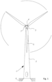
- Fig. 1 illustrates a wind turbine 1 mounted on a foundation 6.
- the wind turbine comprises a tower 2, including a number of tower sections, and a wind turbine nacelle 3 positioned on top of the tower 2.
- the yaw mechanism with a yaw bearing and motors allows the nacelle to turn in relation to the tower in such a way that the wind turbine rotor may face the wind.
- the wind turbine rotor comprising at least one blade and illustrated in the figure with three wind turbine blades 5, is connected to the hub 4 through pitch mechanisms.
- Each pitch mechanism includes a blade bearing 7 which allows the blade to pitch in relation to the wind.
- the hub is connected to the nacelle through a main shaft in the nacelle front.
- the main shaft is directly connected to a generator or indirectly through a gear mechanism and low speed/high speed shafts wherein the connections may comprise one or more shaft bearings such as rotor and generator bearings.
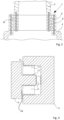
- Fig. 2 illustrates an example of a blade bearing 7 for a wind turbine.
- the wind turbine blade 5 is connected to the inner ring 8 of the blade bearing 7 with a number of bolts.
- the outer ring 9 of the blade bearing is also connected with a number of bolts to the hub 4. Between the raceways of the bearing rings 8, 9 are positioned two rows of bearing balls 10 allowing the wind turbine blade 5 to pitch in relation to the hub 4.
- the wind turbine blade may also be connected to the outer ring and the hub to the inner ring in other embodiments.
- bearings such as 4 point contact ball bearing, thrust bearings (e.g. spherical roller thrust bearings, thrust ball bearings, angular contact thrust ball bearings and cylindrical roller thrust bearings), slewing bearings e.g. three row roller bearings (3RRB) or two row roller + one row ball bearings (2RRB + 1 RBB), or even self-aligning ball bearings, deep groove ball bearings or angular contact ball bearings.
- thrust bearings e.g. spherical roller thrust bearings, thrust ball bearings, angular contact thrust ball bearings and cylindrical roller thrust bearings
- slewing bearings e.g. three row roller bearings (3RRB) or two row roller + one row ball bearings (2RRB + 1 RBB), or even self-aligning ball bearings, deep groove ball bearings or angular contact ball bearings.
- the rollers may for example be cylindrical, needle, tapered, barrel or spherical shaped.
- the bearings may comprise just one row of bearing balls/rollers or more than two rows of bearing balls/rollers such as three rows. Further, the rows may be positioned on top of or next to each other.
- Fig. 3 illustrates contact zones 13 in a slewing bearing according to the invention.
- the contact zones 13 correspond to the raceway of a bearing ring where the rolling elements (illustrated by bearing rollers 11) primarily are in contact with the bearing rings 8, 9 and can transfer load force.
- the contact of the bearing rolling element on the bearing rings may change with the size of load force.
- the bearing is illustrated as a triple row roller bearing (3RRB) but may also include two rows of rollers (upper and lower row; carrying bending/tilt moments as well as axial load force) and a single row (middle row; carrying radial load force) of bearing balls (2 RRB + 1 RBB).
- Contact zones 13 of the six bearing raceways are illustrated with dotted lines. It should be noted that the ends of the rollers secondarily may also have contact to the bearing rings, thereby additional contact zones 14 (only one indicated in fig. 3 ) may also be defined.
- the combined radial and thrust rows of rolling elements in the 3RRB or 2RRB + 1RBB bearing may be used in applications of very heavy loads such as wind turbines or cranes.
- the hardening tool 45 For large bearing rings 40, it is required for the hardening tool 45 to only harden a specific section/fraction of the raceway at a time. Therefore, the blade bearing manufacturer starts at an arbitrary or well-defined location on the bearing ring 40 and then continue round the circumference until the hardening tool 45 is back to the starting position by which a uniform hardening of the full circumference has been carried out. In fig. 4b , the hardening tool 45 is approximately 90° along the circumference, and the difference between the unhardened section 41 and the hardened section 42 is shown.
- the hardening tool 45 could be a machine equipped with a motion system which moves around the bearing ring 40, wherein the motion system is equipped with a coil fed by a power source. Speed and heating power may be set to obtain a desired hardening depth. During the procedure, cooling elements may be used as well to cool the surface heated by the coil pairs when the desired hardening depth has been obtained.
- This 360° hardening process to achieve a uniform hardening depth along the full circumference is the standard process for large bearings and a uniform hardening depth makes sense for most types of bearings, in particular for bearings within fast rotational machinery such as gearboxes, generators, etc. where there is no load-wise difference between the circumferential positions, as they are exposed to the same forces.
- the hardening depth to be applied along the full ring is defined by the most critical load cases. Afterwards, the calculated hardness depth is applied to the full raceway.
- the hardening process can be optimized. Therefore, the processing speed can be increased, and the costs may be reduced. Furthermore, risk of failures during the hardening process may be reduced by applying less deep hardness.
- the depth of hardening can be influenced by several factors, including the frequency and power of the induction field, the speed of the tool, and the temperature of the part during heating.
- the speed of the tool and the temperature range used for induction hardening of large rings for bearings can vary depending on the specific application and material being processed.
- heating temperatures may range from 800°C to 1100°C and that the speed of the tool may be 0.1-10 meters per minute (m/min), such as 0.5-5 m/min. This speed refers to the rate at which the part moves through the induction coil during heating.
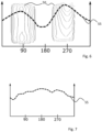
- Figs. 5-7 illustrate some examples of variable hardening depth.
- the x-axis indicates the circumferential position on the bearing ( ⁇ from 0-360°), whereas the y-axis indicates the hardening depth for each circumferential position.
- a step-curve could be used with 90° keeping a constant depth along line 51, the opposite 90° keeping a constant depth along line 52 and then connecting the two line segments with curved or linear lines.
- Fig. 7 shows a situation where the hardening variation is fully optimized to the exact load cases/required hardening depth in any circumferential position. This results in a hardening depth profile 55 as shown.
- curves may be advantageous to define curves as resulting function of a number of combined overlapping functions, for instance trigonometric functions. Such functions may allow the steering of the hardening depth by varying temperature or speed or a combination thereof.
Landscapes
- Engineering & Computer Science (AREA)
- Chemical & Material Sciences (AREA)
- Mechanical Engineering (AREA)
- General Engineering & Computer Science (AREA)
- Materials Engineering (AREA)
- Crystallography & Structural Chemistry (AREA)
- Physics & Mathematics (AREA)
- Metallurgy (AREA)
- Organic Chemistry (AREA)
- Thermal Sciences (AREA)
- Manufacturing & Machinery (AREA)
- Rolling Contact Bearings (AREA)
- Wind Motors (AREA)
Abstract
Description
- The invention relates to a bearing ring, a bearing ring, a wind turbine and methods of manufacturing a bearing ring.
- Bearings are used in a wide variety of technical fields in order to support, guide, and reduce the friction of motion between different parts such as between fixed and moving parts. The bearings may face very high loads in some technical fields such as in the wind turbine area.
- Hardening of the raceway is applied to most rolling element bearings. The raceways of bearings are hardened to improve the resistance to wear and fatigue, which resolves in an overall improvement in reliability. The conventional methods for hardening involve case hardening, induction hardening, nitriding, carburizing, case hardening and cryogenic hardening. For larger bearings, as wind turbine bearings, case and induction hardening is frequently used. During case hardening the surface of the bearing is heated and then quenched to create a hard outer layer, while leaving the core of the bearing relatively soft and ductile. Induction hardening uses a high-frequency electrical current to heat the surface of the bearing. This process allows selective hardening of specific parts of the raceway in a uniform and precise manner. Because the hardening tool hardens a specific section/fraction of the raceway at a time, the manufacturer starts at an arbitrary or well-defined location on the bearing rings and then continue round the circumference until the hardening tool is back to the starting position by which a uniform hardening of the full circumference has been carried out.
-
EP1977126 describes that overlapping of the starting and finishing positions in the hardening process is not allowed in order to avoid annealing of the already hardened raceway to avoid unpredictable material characteristics. As a consequence hereof a small portion of the raceway is less hardened i.e. "soft spots" in the hardened raceway. - It is an object of the present invention to establish an improved hardening process for bearing rings.
- The hardening depth is usually sought to be consistent over the entire circumference of the raceway of bearing rings. However, according to the present invention, in particular for large slewing bearings with defined load distribution, it may be advantageous to adapt the machine parameters to adapt the hardening depth over the circumference.
- As less hardening depth is needed in specific sections of the ring, the hardening process can be optimized. Therefore, the processing speed can be increased, and the costs may be reduced. In addition, failures can be avoided, which can be caused by deep hardening.
- The invention therefore provides for a bearing ring comprising at least one raceway, wherein said at least one raceway has been hardened in a hardening process resulting in a hardening depth profile, wherein said hardening depth profile is defined between a maximum hardening depth and a minimum hardening depth, and wherein the hardening depth profile has the value of maximum hardening depth in less than 180° of the circumference of the bearing ring, preferably less than 90°.
- The hardness depth of the bearing secures that the needed material requirements meet subsurface stresses from extreme and fatigue loads. Therefore, the hardness depth is dependent on the loads. Typically, in prior art, the final hardening depth is defined by the most critical load cases. Afterwards, the calculated hardness depth is applied to the full raceway.
- However, the typical load cases for large slewing bearings with defined load distribution is significantly impacted by the bending moments. Therefore, according to the present invention, it has been realized that cost and process time can be reduced by varying the hardness depth over the circumference of the raceway by adapting the machining process. Therefore, lower loaded sections of the bearing would have less hardening depth.
- In particular, the bearings of a wind turbine generally work in heavy load conditions where they may experience axial and radial forces as well as large bending/tilt moments.
- Especially, blade bearings work under heavy load conditions because of the presence of axial and radial forces as well as large bending/tilt moments while performing limited oscillating movements instead of a continuous rotating motion.
- As mentioned above, said hardening depth profile is defined between a maximum hardening depth and a minimum hardening depth, and wherein the hardening depth profile has the value of maximum hardening depth in less than 180° of the circumference of the bearing ring, preferably less than 90°. Ideally, the hardening depth profile provides a hardening depth along the full circumference of the bearing ring, fitting substantially which level of hardening is needed. Consequently, the maximum hardening depth may in preferred embodiments only be present in less than 45°, or even less than 20° of the full circumference.
- In an embodiment of the invention, said hardening process is an induction hardening process.
- In an embodiment of the invention, said hardening depth profile is defined by a function including at least one trigonometric function.
- In an embodiment of the invention, said hardening depth profile is defined by a combination of multiple periodic functions.
- In an embodiment of the invention, said hardening depth profile is at least partly designed based on an expected load distribution along the 360° circumference of the bearing ring.
- Further, the invention relates to a bearing comprising at least two bearing rings with at least one raceway as described here above, and at least one row of bearing rolling elements positioned between said bearing rings and in contact with each of said at least one raceway.
- In embodiments of the invention, said bearing rolling elements are bearing balls or rollers or combinations hereof.
- Further, the invention relates to a wind turbine comprising one or more bearings as described here above.
- In an embodiment of the invention, said one or more bearings are one or more blade bearings.
- Further, the invention provides for a method of manufacturing a bearing ring comprising at least one raceway, said method comprising the step of hardening said at least one raceway in a hardening process including a hardening tool resulting in a hardening depth profile, wherein said hardening process includes varying a process parameter of the hardening tool during the hardening process.
- In an embodiment of the invention, said process parameter is at least one selected from the group consisting of frequency, power, temperature and speed.
- The invention will be described in the following with reference to the figures in which
- fig. 1
- illustrates a wind turbine,
- fig. 2
- illustrates an example of a blade bearing for a wind turbine,
- fig. 3
- illustrates a 3RRB indicating contact zones,
- fig. 4a and 4b
- illustrates a hardening process,
- figs. 5-7
- illustrate examples of variable hardening depth.
-
Fig. 1 illustrates a wind turbine 1 mounted on afoundation 6. The wind turbine comprises atower 2, including a number of tower sections, and awind turbine nacelle 3 positioned on top of thetower 2. The yaw mechanism with a yaw bearing and motors allows the nacelle to turn in relation to the tower in such a way that the wind turbine rotor may face the wind. - The wind turbine rotor, comprising at least one blade and illustrated in the figure with three
wind turbine blades 5, is connected to the hub 4 through pitch mechanisms. Each pitch mechanism includes a blade bearing 7 which allows the blade to pitch in relation to the wind. The hub is connected to the nacelle through a main shaft in the nacelle front. The main shaft is directly connected to a generator or indirectly through a gear mechanism and low speed/high speed shafts wherein the connections may comprise one or more shaft bearings such as rotor and generator bearings. -
Fig. 2 illustrates an example of a blade bearing 7 for a wind turbine. Thewind turbine blade 5 is connected to theinner ring 8 of the blade bearing 7 with a number of bolts. The outer ring 9 of the blade bearing is also connected with a number of bolts to the hub 4. Between the raceways of the bearing rings 8, 9 are positioned two rows of bearingballs 10 allowing thewind turbine blade 5 to pitch in relation to the hub 4. - The wind turbine blade may also be connected to the outer ring and the hub to the inner ring in other embodiments.
- Other types of bearings will be known to the skilled person within the technical area of bearings such as 4 point contact ball bearing, thrust bearings (e.g. spherical roller thrust bearings, thrust ball bearings, angular contact thrust ball bearings and cylindrical roller thrust bearings), slewing bearings e.g. three row roller bearings (3RRB) or two row roller + one row ball bearings (2RRB + 1 RBB), or even self-aligning ball bearings, deep groove ball bearings or angular contact ball bearings.
- The rollers may for example be cylindrical, needle, tapered, barrel or spherical shaped.
- Further, the bearings may comprise just one row of bearing balls/rollers or more than two rows of bearing balls/rollers such as three rows. Further, the rows may be positioned on top of or next to each other.
- Even though the patent claims herein refer to bearing rings with at least one raceway, it should be clear that the adjusted hardening process as described herein could be used for multiple raceways in a bearing or bearing ring, either with identical hardening depth profiles, or for different rows of rolling elements, different hardening depth profiles may be advantageously used.
-
Fig. 3 illustratescontact zones 13 in a slewing bearing according to the invention. Thecontact zones 13 correspond to the raceway of a bearing ring where the rolling elements (illustrated by bearing rollers 11) primarily are in contact with the bearing rings 8, 9 and can transfer load force. The contact of the bearing rolling element on the bearing rings may change with the size of load force. - The bearing is illustrated as a triple row roller bearing (3RRB) but may also include two rows of rollers (upper and lower row; carrying bending/tilt moments as well as axial load force) and a single row (middle row; carrying radial load force) of bearing balls (2 RRB + 1 RBB). Contact
zones 13 of the six bearing raceways are illustrated with dotted lines. It should be noted that the ends of the rollers secondarily may also have contact to the bearing rings, thereby additional contact zones 14 (only one indicated infig. 3 ) may also be defined. - The combined radial and thrust rows of rolling elements in the 3RRB or 2RRB + 1RBB bearing may be used in applications of very heavy loads such as wind turbines or cranes.
- It is well-known and standard procedure to harden those parts of bearing rings that are most exposed to loads/forces, i.e. the
contact zones figs. 4a and 4b . - For large bearing rings 40, it is required for the hardening
tool 45 to only harden a specific section/fraction of the raceway at a time. Therefore, the blade bearing manufacturer starts at an arbitrary or well-defined location on thebearing ring 40 and then continue round the circumference until the hardeningtool 45 is back to the starting position by which a uniform hardening of the full circumference has been carried out. Infig. 4b , the hardeningtool 45 is approximately 90° along the circumference, and the difference between theunhardened section 41 and thehardened section 42 is shown. - The hardening
tool 45 could be a machine equipped with a motion system which moves around the bearingring 40, wherein the motion system is equipped with a coil fed by a power source. Speed and heating power may be set to obtain a desired hardening depth. During the procedure, cooling elements may be used as well to cool the surface heated by the coil pairs when the desired hardening depth has been obtained. - This 360° hardening process to achieve a uniform hardening depth along the full circumference is the standard process for large bearings and a uniform hardening depth makes sense for most types of bearings, in particular for bearings within fast rotational machinery such as gearboxes, generators, etc. where there is no load-wise difference between the circumferential positions, as they are exposed to the same forces. Typically, the hardening depth to be applied along the full ring is defined by the most critical load cases. Afterwards, the calculated hardness depth is applied to the full raceway.
- However, according to the present invention, it has been realized that for large slewing bearings with defined load distribution, (such as a crane bearing or a wind turbine blade bearing) it makes sense to adapt the machine parameters to adapt the hardening depth over the circumference.
- As less hardening depth is needed in specific sections of the ring, the hardening process can be optimized. Therefore, the processing speed can be increased, and the costs may be reduced. Furthermore, risk of failures during the hardening process may be reduced by applying less deep hardness.
- Different hardening procedures can be considered to vary the hardening depth over the circumference. I.e. for induction hardening, the depth of hardening can be influenced by several factors, including the frequency and power of the induction field, the speed of the tool, and the temperature of the part during heating.
- The speed of the tool and the temperature range used for induction hardening of large rings for bearings can vary depending on the specific application and material being processed.
- Some examples could be that heating temperatures may range from 800°C to 1100°C and that the speed of the tool may be 0.1-10 meters per minute (m/min), such as 0.5-5 m/min. This speed refers to the rate at which the part moves through the induction coil during heating.
- A standard hardening process described in short:
- The required hardness is achieved by heating the particular area for a specific time.
- Due to the size of blade bearings, a movable heating source is used.
- The industry standard uses a constant temperature and speed of the movable heating source.
- The hardening depth reaches typically several millimeters
- Improvements in relation to the present invention:
- By enabling changed temperature/speed during the hardening process, varying hardness is made achievable.
- Cost-savings may be obtained, possibly in the range of 150€ per 1 mm hardening depth of a bearing ring. Consequently, lowering hardening depth on average 1 mm on each blade bearing ring for a wind turbine may be a 900€ saving.
-
Figs. 5-7 illustrate some examples of variable hardening depth. In all figures, the x-axis indicates the circumferential position on the bearing (θ from 0-360°), whereas the y-axis indicates the hardening depth for each circumferential position. - Focusing now on
fig. 5 , in a greyish color in the background, indicated with 50, is an indication of where the loads are strongest along the circumference of the bearing. It can be seen that the loads are max in a range around 270°. Theline 51 indicates the maximum hardening depth, and which would be the hardening depth given to the full circumference in prior art methods.Line 52 indicates the minimum hardening depth needed regardless of circumferential position. - Different hardening depth profiles 55 would be suitable for a case like this, where a most simple one is shown, where the variable hardening depth is a simple sinusoidal curve 55 (shifted sideways as our θ=0° is randomly positioned). Alternatively, a step-curve could be used with 90° keeping a constant depth along
line 51, the opposite 90° keeping a constant depth alongline 52 and then connecting the two line segments with curved or linear lines. - A more complex situation is shown in
fig. 6 , where the greyish color in the background, similar tofig. 5 and again indicated with 50, indicates two ranges along the circumference where the loads are increased, around 90° and around 260°. In this case, the hardeningdepth profile 55 is a more complicated curve. -
Fig. 7 shows a situation where the hardening variation is fully optimized to the exact load cases/required hardening depth in any circumferential position. This results in a hardeningdepth profile 55 as shown. - Regardless of the complexity of the desired curves, for programming reasons for the hardening process, it is believed to be advantageous to define curves as resulting function of a number of combined overlapping functions, for instance trigonometric functions. Such functions may allow the steering of the hardening depth by varying temperature or speed or a combination thereof.
- The invention has been exemplified above with reference to specific examples of blade bearings in a wind turbine. However, it should be understood that the invention is not limited to the particular examples but may be designed and altered in a multitude of varieties within the scope of the invention as specified in the claims e.g. in relation to other wind turbine bearing as well as other applications involving very large bearings facing axial and radial load forces as well as bending/tilting moments such as large crane, radar or satellite aerial bearings.
Claims (12)
- A bearing ring (8, 9) comprising at least one raceway (13)wherein said at least one raceway (13) has been hardened in a hardening process resulting in a hardening depth profile (55),wherein said hardening depth profile (55) is defined between a maximum hardening depth (51) and a minimum hardening depth (52),characterised in thatthe hardening depth profile (55) has the value of maximum hardening depth (51) in less than 180° of the circumference of the bearing ring, preferably less than 90°.
- A bearing ring (8, 9) according to claim 1, wherein said hardening process is an induction hardening process.
- A bearing ring (8, 9) according to claim 1 or 2, wherein said hardening depth profile (55) is defined by a function including at least one trigonometric function.
- A bearing ring (8, 9) according to any preceding claim, wherein said hardening depth profile (55) is defined by a combination of multiple periodic functions.
- A bearing ring (8, 9) according to any preceding claim, wherein said hardening depth profile (55) is at least partly designed based on an expected load distribution along the 360° circumference of the bearing ring.
- A bearing (7) comprisingat least two bearing rings (8, 9) with at least one raceway (13) according to any preceding claims, andat least one row of bearing rolling elements (10, 11) positioned between said bearing rings and in contact with each of said at least one raceway (13).
- A bearing (7) according to claim 6, wherein said bearing rolling elements are bearing balls (11) or rollers (15) or combinations hereof.
- A wind turbine (1) comprising one or more bearings (7) according to claim 6 or 7.
- A wind turbine according to claim 8, wherein said one or more bearings (7) are one or more blade bearings.
- Method of manufacturing a bearing ring (8, 9) comprising at least one raceway (13), said method comprising the step of hardening said at least one raceway (13) in a hardening process including a hardening tool (45) resulting in a hardening depth profile (55), wherein said hardening process includes varying a process parameter of the hardening tool (45) during the hardening process.
- A method according to claim 10, wherein said process parameter is at least one selected from the group consisting of frequency, power, temperature and speed.
- A method according to claim 10 or 11, further limited by the characterizing parts of any of claims 1-5.
Priority Applications (4)
| Application Number | Priority Date | Filing Date | Title |
|---|---|---|---|
| EP23171565.7A EP4459147A1 (en) | 2023-05-04 | 2023-05-04 | A bearing ring, a bearing, a wind turbine and method of manufacturing a bearing ring |
| JP2025564237A JP2026516021A (en) | 2023-05-04 | 2024-04-30 | Bearing ring, bearing, wind turbine, and method for manufacturing a bearing ring |
| CN202480028146.9A CN121079513A (en) | 2023-05-04 | 2024-04-30 | Bearing ring, bearing, wind turbine and method of manufacturing a bearing ring |
| PCT/DK2024/050100 WO2024227490A1 (en) | 2023-05-04 | 2024-04-30 | A bearing ring, a bearing, a wind turbine and methods of manufacturing a bearing ring |
Applications Claiming Priority (1)
| Application Number | Priority Date | Filing Date | Title |
|---|---|---|---|
| EP23171565.7A EP4459147A1 (en) | 2023-05-04 | 2023-05-04 | A bearing ring, a bearing, a wind turbine and method of manufacturing a bearing ring |
Publications (1)
| Publication Number | Publication Date |
|---|---|
| EP4459147A1 true EP4459147A1 (en) | 2024-11-06 |
Family
ID=86329816
Family Applications (1)
| Application Number | Title | Priority Date | Filing Date |
|---|---|---|---|
| EP23171565.7A Pending EP4459147A1 (en) | 2023-05-04 | 2023-05-04 | A bearing ring, a bearing, a wind turbine and method of manufacturing a bearing ring |
Country Status (4)
| Country | Link |
|---|---|
| EP (1) | EP4459147A1 (en) |
| JP (1) | JP2026516021A (en) |
| CN (1) | CN121079513A (en) |
| WO (1) | WO2024227490A1 (en) |
Citations (3)
| Publication number | Priority date | Publication date | Assignee | Title |
|---|---|---|---|---|
| EP1977126A1 (en) | 2006-01-23 | 2008-10-08 | Vestas Wind Systems A/S | A bearing, a wind turbine and methods of manufacturing a bearing |
| US20150368735A1 (en) * | 2012-02-17 | 2015-12-24 | Thyssenkrupp Rothe Erde Gmbh | Method for induction surface hardening of a ring surface |
| DE102020205669A1 (en) * | 2020-05-05 | 2021-11-11 | Thyssenkrupp Ag | Method for producing ring segments and ring segments for a segmented rolling bearing ring with a hardened rolling bearing raceway |
-
2023
- 2023-05-04 EP EP23171565.7A patent/EP4459147A1/en active Pending
-
2024
- 2024-04-30 WO PCT/DK2024/050100 patent/WO2024227490A1/en not_active Ceased
- 2024-04-30 CN CN202480028146.9A patent/CN121079513A/en active Pending
- 2024-04-30 JP JP2025564237A patent/JP2026516021A/en active Pending
Patent Citations (4)
| Publication number | Priority date | Publication date | Assignee | Title |
|---|---|---|---|---|
| EP1977126A1 (en) | 2006-01-23 | 2008-10-08 | Vestas Wind Systems A/S | A bearing, a wind turbine and methods of manufacturing a bearing |
| EP1977126B1 (en) * | 2006-01-23 | 2009-10-28 | Vestas Wind Systems A/S | A bearing, a wind turbine and methods of manufacturing a bearing |
| US20150368735A1 (en) * | 2012-02-17 | 2015-12-24 | Thyssenkrupp Rothe Erde Gmbh | Method for induction surface hardening of a ring surface |
| DE102020205669A1 (en) * | 2020-05-05 | 2021-11-11 | Thyssenkrupp Ag | Method for producing ring segments and ring segments for a segmented rolling bearing ring with a hardened rolling bearing raceway |
Also Published As
| Publication number | Publication date |
|---|---|
| JP2026516021A (en) | 2026-05-19 |
| WO2024227490A1 (en) | 2024-11-07 |
| CN121079513A (en) | 2025-12-05 |
Similar Documents
| Publication | Publication Date | Title |
|---|---|---|
| AU2006336103B2 (en) | A bearing, a wind turbine and methods of manufacturing a bearing | |
| EP2458023B1 (en) | Method for heat-treating a ring-shaped member, method for producing a ring-shaped member, ring-shaped member, bearing ring, rolling bearing, and method for producing a bearing ring | |
| EP2373899B1 (en) | Compound steel bearings and methods of manufacturing | |
| EP2666875B1 (en) | Method for manufacturing bearing ring, bearing ring | |
| EP2772555B1 (en) | Ring-shaped member heat treatment method and ring-shaped member manufacturing method | |
| CN105715676B (en) | Double row spherical roller bearing, method of manufacturing and wind turbine bearing structure | |
| US10378076B2 (en) | Double row tapered roller bearing, bearing ring, and method for producing double row tapered roller bearing | |
| US10718377B2 (en) | Method for producing bearing ring, double row tapered roller bearing, and method for producing double row tapered roller bearing | |
| WO2024227490A1 (en) | A bearing ring, a bearing, a wind turbine and methods of manufacturing a bearing ring | |
| CN102803768B (en) | Raceway elements and bearing arrangements for large rolling bearings | |
| US20150219159A1 (en) | Bearing having a raceway with high chromium content | |
| WO2018166661A1 (en) | Method of finishing a bearing ring | |
| EP3369954A1 (en) | Method for manufacturing bearing ring and method for manufacturing multi-row tapered roller bearing | |
| US12110926B2 (en) | Method for increasing the load-bearing capacity, and rolling device for hard rolling a surface-hardened rolling-bearing raceway | |
| CN121719835A (en) | Pitch bearing, wind driven generator and wind driven generator | |
| JP2017082300A (en) | Manufacturing method of bearing ring and double row tapered roller bearing | |
| JP2017082943A (en) | Process of manufacture of bearing ring and process of manufacture of double row conical roller bearing |
Legal Events
| Date | Code | Title | Description |
|---|---|---|---|
| PUAI | Public reference made under article 153(3) epc to a published international application that has entered the european phase |
Free format text: ORIGINAL CODE: 0009012 |
|
| STAA | Information on the status of an ep patent application or granted ep patent |
Free format text: STATUS: THE APPLICATION HAS BEEN PUBLISHED |
|
| AK | Designated contracting states |
Kind code of ref document: A1 Designated state(s): AL AT BE BG CH CY CZ DE DK EE ES FI FR GB GR HR HU IE IS IT LI LT LU LV MC ME MK MT NL NO PL PT RO RS SE SI SK SM TR |
|
| STAA | Information on the status of an ep patent application or granted ep patent |
Free format text: STATUS: REQUEST FOR EXAMINATION WAS MADE |
|
| 17P | Request for examination filed |
Effective date: 20250314 |
|
| STAA | Information on the status of an ep patent application or granted ep patent |
Free format text: STATUS: EXAMINATION IS IN PROGRESS |
|
| 17Q | First examination report despatched |
Effective date: 20251217 |
|
| GRAP | Despatch of communication of intention to grant a patent |
Free format text: ORIGINAL CODE: EPIDOSNIGR1 |
|
| STAA | Information on the status of an ep patent application or granted ep patent |
Free format text: STATUS: GRANT OF PATENT IS INTENDED |
|
| RIC1 | Information provided on ipc code assigned before grant |
Ipc: F16C 33/58 20060101AFI20260616BHEP Ipc: F16C 33/64 20060101ALI20260616BHEP Ipc: C21D 1/10 20060101ALI20260616BHEP Ipc: C21D 9/40 20060101ALI20260616BHEP |
|
| GRAJ | Information related to disapproval of communication of intention to grant by the applicant or resumption of examination proceedings by the epo deleted |
Free format text: ORIGINAL CODE: EPIDOSDIGR1 |
|
| INTG | Intention to grant announced |
Effective date: 20260630 |
|
| STAA | Information on the status of an ep patent application or granted ep patent |
Free format text: STATUS: EXAMINATION IS IN PROGRESS |