EP4459142A1 - Rotating shaft mechanism and foldable terminal device - Google Patents
Rotating shaft mechanism and foldable terminal device Download PDFInfo
- Publication number
- EP4459142A1 EP4459142A1 EP23838478.8A EP23838478A EP4459142A1 EP 4459142 A1 EP4459142 A1 EP 4459142A1 EP 23838478 A EP23838478 A EP 23838478A EP 4459142 A1 EP4459142 A1 EP 4459142A1
- Authority
- EP
- European Patent Office
- Prior art keywords
- rotating shaft
- accommodating groove
- side plate
- limiting layer
- limiting
- Prior art date
- Legal status (The legal status is an assumption and is not a legal conclusion. Google has not performed a legal analysis and makes no representation as to the accuracy of the status listed.)
- Granted
Links
Images







Classifications
-
- F—MECHANICAL ENGINEERING; LIGHTING; HEATING; WEAPONS; BLASTING
- F16—ENGINEERING ELEMENTS AND UNITS; GENERAL MEASURES FOR PRODUCING AND MAINTAINING EFFECTIVE FUNCTIONING OF MACHINES OR INSTALLATIONS; THERMAL INSULATION IN GENERAL
- F16C—SHAFTS; FLEXIBLE SHAFTS; ELEMENTS OR CRANKSHAFT MECHANISMS; ROTARY BODIES OTHER THAN GEARING ELEMENTS; BEARINGS
- F16C11/00—Pivots; Pivotal connections
- F16C11/04—Pivotal connections
-
- G—PHYSICS
- G06—COMPUTING OR CALCULATING; COUNTING
- G06F—ELECTRIC DIGITAL DATA PROCESSING
- G06F1/00—Details not covered by groups G06F3/00 - G06F13/00 and G06F21/00
- G06F1/16—Constructional details or arrangements
-
- H—ELECTRICITY
- H04—ELECTRIC COMMUNICATION TECHNIQUE
- H04M—TELEPHONIC COMMUNICATION
- H04M1/00—Substation equipment, e.g. for use by subscribers
- H04M1/02—Constructional features of telephone sets
- H04M1/0202—Portable telephone sets, e.g. cordless phones, mobile phones or bar type handsets
- H04M1/0206—Portable telephones comprising a plurality of mechanically joined movable body parts, e.g. hinged housings
- H04M1/0208—Portable telephones comprising a plurality of mechanically joined movable body parts, e.g. hinged housings characterized by the relative motions of the body parts
- H04M1/0214—Foldable telephones, i.e. with body parts pivoting to an open position around an axis parallel to the plane they define in closed position
- H04M1/0216—Foldable in one direction, i.e. using a one degree of freedom hinge
-
- F—MECHANICAL ENGINEERING; LIGHTING; HEATING; WEAPONS; BLASTING
- F16—ENGINEERING ELEMENTS AND UNITS; GENERAL MEASURES FOR PRODUCING AND MAINTAINING EFFECTIVE FUNCTIONING OF MACHINES OR INSTALLATIONS; THERMAL INSULATION IN GENERAL
- F16C—SHAFTS; FLEXIBLE SHAFTS; ELEMENTS OR CRANKSHAFT MECHANISMS; ROTARY BODIES OTHER THAN GEARING ELEMENTS; BEARINGS
- F16C11/00—Pivots; Pivotal connections
- F16C11/04—Pivotal connections
- F16C11/10—Arrangements for locking
- F16C11/103—Arrangements for locking frictionally clamped
-
- F—MECHANICAL ENGINEERING; LIGHTING; HEATING; WEAPONS; BLASTING
- F16—ENGINEERING ELEMENTS AND UNITS; GENERAL MEASURES FOR PRODUCING AND MAINTAINING EFFECTIVE FUNCTIONING OF MACHINES OR INSTALLATIONS; THERMAL INSULATION IN GENERAL
- F16C—SHAFTS; FLEXIBLE SHAFTS; ELEMENTS OR CRANKSHAFT MECHANISMS; ROTARY BODIES OTHER THAN GEARING ELEMENTS; BEARINGS
- F16C11/00—Pivots; Pivotal connections
- F16C11/04—Pivotal connections
- F16C11/12—Pivotal connections incorporating flexible connections, e.g. leaf springs
-
- G—PHYSICS
- G06—COMPUTING OR CALCULATING; COUNTING
- G06F—ELECTRIC DIGITAL DATA PROCESSING
- G06F1/00—Details not covered by groups G06F3/00 - G06F13/00 and G06F21/00
- G06F1/16—Constructional details or arrangements
- G06F1/1613—Constructional details or arrangements for portable computers
- G06F1/1633—Constructional details or arrangements of portable computers not specific to the type of enclosures covered by groups G06F1/1615 - G06F1/1626
- G06F1/1675—Miscellaneous details related to the relative movement between the different enclosures or enclosure parts
- G06F1/1681—Details related solely to hinges
-
- H—ELECTRICITY
- H04—ELECTRIC COMMUNICATION TECHNIQUE
- H04M—TELEPHONIC COMMUNICATION
- H04M1/00—Substation equipment, e.g. for use by subscribers
- H04M1/02—Constructional features of telephone sets
- H04M1/0202—Portable telephone sets, e.g. cordless phones, mobile phones or bar type handsets
- H04M1/0206—Portable telephones comprising a plurality of mechanically joined movable body parts, e.g. hinged housings
- H04M1/0208—Portable telephones comprising a plurality of mechanically joined movable body parts, e.g. hinged housings characterized by the relative motions of the body parts
- H04M1/0214—Foldable telephones, i.e. with body parts pivoting to an open position around an axis parallel to the plane they define in closed position
- H04M1/0216—Foldable in one direction, i.e. using a one degree of freedom hinge
- H04M1/022—The hinge comprising two parallel pivoting axes
-
- H—ELECTRICITY
- H05—ELECTRIC TECHNIQUES NOT OTHERWISE PROVIDED FOR
- H05K—PRINTED CIRCUITS; CASINGS OR CONSTRUCTIONAL DETAILS OF ELECTRIC APPARATUS; MANUFACTURE OF ASSEMBLAGES OF ELECTRICAL COMPONENTS
- H05K5/00—Casings, cabinets or drawers for electric apparatus
- H05K5/02—Details
- H05K5/0217—Mechanical details of casings
- H05K5/0226—Hinges
-
- H—ELECTRICITY
- H04—ELECTRIC COMMUNICATION TECHNIQUE
- H04M—TELEPHONIC COMMUNICATION
- H04M1/00—Substation equipment, e.g. for use by subscribers
- H04M1/02—Constructional features of telephone sets
- H04M1/0202—Portable telephone sets, e.g. cordless phones, mobile phones or bar type handsets
- H04M1/026—Details of the structure or mounting of specific components
- H04M1/0266—Details of the structure or mounting of specific components for a display module assembly
- H04M1/0268—Details of the structure or mounting of specific components for a display module assembly including a flexible display panel
Definitions
- This application relates to a rotating shaft mechanism and a foldable terminal device.
- a foldable terminal device has two poses: unfolded and folded.
- a rotating shaft mechanism is an important component for unfolding and folding the foldable terminal device.
- a transmission mechanism inside the rotating shaft mechanism is prone to a problem during transmission, and this not only affects user experience, but also shortens a service life of a part.
- Embodiments of this application provide a rotating shaft mechanism and a foldable terminal device, to resolve a problem of abnormal sound that is caused by collision between parts when the rotating shaft mechanism rotates.
- An embodiment of this application provides a rotating shaft mechanism, including a rotating shaft base, a shaft cover assembly, a rotating shaft, a centrifugal part, and a limiting member.
- the shaft cover assembly is disposed on a side of the rotating shaft base in a thickness direction of the rotating shaft base, and an accommodating groove is disposed in the shaft cover assembly.
- the rotating shaft is rotatably disposed on the rotating shaft base.
- the centrifugal part is fixedly disposed at one end of the rotating shaft, and the centrifugal part deviates from an axis of the rotating shaft.
- the centrifugal part is rotatably disposed in the accommodating groove and is in clearance fit with the accommodating groove.
- the rotating shaft drives, by using the centrifugal part, the shaft cover assembly to move in the thickness direction of the rotating shaft base.
- the limiting member is at least partially located in the accommodating groove. The limiting member is configured to abut against the centrifugal part in rotation.
- the centrifugal part when the rotating shaft rotates, the centrifugal part can be driven to rotate in the accommodating groove around the axis of the rotating shaft. Rotation of the centrifugal part can drive the shaft cover assembly to move in the thickness direction of the rotating shaft base.
- the limiting member is at least partially located in the accommodating groove, and can abut against the centrifugal part when the centrifugal part rotates. Therefore, when the centrifugal part rotates, the limiting member can fill at least a gap between the accommodating groove and the centrifugal part. When the centrifugal part rotates, the centrifugal part can limit rotation or displacement of the limiting member relative to an inner wall of the accommodating groove, thereby reducing abnormal sound.
- the limiting member includes a first limiting layer, the first limiting layer is disposed on the inner wall of the accommodating groove, and the centrifugal part abuts against the first limiting layer.
- the first limiting layer may be laid on the inner wall of the accommodating groove, and may occupy a relatively large area. Therefore, the centrifugal part may have a relatively large contact area with the inner wall of the accommodating groove, so that stability can be enhanced when the centrifugal part rotates in the accommodating groove.
- the shaft cover assembly includes a lifting/lowering block and a shaft cover that are fixedly disposed relative to each other, the shaft cover is disposed on a side that is of the lifting/lowering block and that is away from the rotating shaft base, and the accommodating groove is disposed in the lifting/lowering block. Therefore, when the shaft cover assembly moves in the thickness direction of the rotating shaft base, the shaft cover is driven by the lifting/lowering block to move.
- the lifting/lowering block is used as a position for disposing the accommodating groove.
- the limiting member further includes a second limiting layer and a connecting part, the second limiting layer is disposed on an outer wall of the lifting/lowering block, the inner wall of the accommodating groove is opposite to the outer wall of the lifting/lowering block, and the first limiting layer and the second limiting layer are connected by using the connecting part.
- the first limiting layer and the second limiting layer are sandwiched between the inner wall of the accommodating groove and the outer wall of the lifting/lowering block, so that the first limiting layer can be prevented from detaching from the accommodating groove due to sliding friction when the centrifugal part rotates.
- the lifting/lowering block includes a bottom plate and a first side plate.
- the bottom plate and the first side plate enclose to form at least a portion of the accommodating groove.
- An inlet of the accommodating groove is opposite to the bottom plate, and a plane on which the first side plate is located extends along the axis of the rotating shaft.
- the first limiting layer is located on a surface that is of the first side plate and that faces an interior of the accommodating groove
- the second limiting layer is located on a surface that is of the first side plate and that is away from the interior of the accommodating groove.
- the connecting part is connected to the first limiting layer and the second limiting layer through the inlet of the accommodating groove.
- the first limiting layer and the second limiting layer are respectively clamped on two surfaces of the first side plate.
- the first limiting layer can abut against a side wall of the limiting member, to increase a contact area between the first limiting layer and the limiting member.
- a protruding structure protruding toward the interior of the accommodating groove is disposed at the first limiting layer, and the protruding structure abuts against the centrifugal part.
- the protruding structure may have specific elasticity, and therefore, a buffering effect can be achieved for a centrifugal post when the centrifugal post shakes.
- the protruding structure is disposed on a middle portion of the first limiting layer. Two ends of the first limiting layer respectively abut against the surface that is of the first side plate and that faces the accommodating groove.
- force when the protruding structure is squeezed by the centrifugal post, force may be transferred to the first side plate by using two end parts of the first limiting layer.
- the protruding structure is located at one end that is of the first limiting layer and that is close to the bottom plate.
- the protruding structure is disposed at the end that is of the first limiting layer and that is close to the bottom plate, so that limitation on an end part of the limiting member can be enhanced, thereby avoiding collision between the limiting member and the bottom of the accommodating groove.
- the lifting/lowering block includes a second side plate and a third side plate. Planes on which the second side plate and the third side plate are located extend along the axis of the rotating shaft, and are respectively located at two opposite ends of the first side plate.
- the bottom plate, the first side plate, the second side plate, and the third side plate enclose to form at least a portion of the accommodating groove.
- the first side plate, the second side plate, and the third side plate enclose the outer wall of the lifting/lowering block to form a first limiting groove, and the second limiting layer is located in the first limiting groove.
- the first limiting groove is formed by using the bottom plate, the first side plate, the second side plate, and the third side plate.
- a structure is simple, and a position of the second limiting layer can be limited, to prevent the second limiting layer from detaching from the outer wall of the lifting/lowering block.
- the first side plate, the second side plate, and the third side plate enclose the inner wall of the accommodating groove to form a second limiting groove, and the first limiting layer is located in the second limiting groove.
- the second limiting groove is formed by using the bottom plate, the first side plate, the second side plate, and the third side plate.
- a structure is simple, and a position of the first limiting layer can be limited, to prevent the first limiting layer from detaching from the inner wall of the accommodating groove.
- the lifting/lowering block includes a bottom plate, a first side plate, and a fourth side plate.
- An inlet of the accommodating groove is opposite to the bottom plate.
- a plane on which the first side plate is located and a plane on which the fourth side plate is located extend along the axis of the rotating shaft.
- the fourth side plate is opposite to the first side plate.
- the bottom plate, the first side plate, and the fourth side plate enclose to form at least a portion of the accommodating groove.
- the first limiting layer is located on a surface that is of the bottom plate and that faces an interior of the accommodating groove
- the second limiting layer is located on a surface that is of the bottom plate and that is away from the interior of the accommodating groove.
- the connecting part is connected to the first limiting layer and the second limiting layer through an opening located between the first side plate and the fourth side plate.
- the first limiting layer and the second limiting layer are clamped on two sides of the bottom plate, and the second limiting layer is limited to a bottom wall of the accommodating groove, so that collision caused by the limiting member to the bottom wall of the accommodating groove can be reduced, and abnormal sound can be reduced.
- the first limiting layer, the connecting part, and the second limiting layer are formed integrally. Overall strength of the limiting member is enhanced.
- the first limiting layer, the connecting part, and the second limiting layer are metal sheets. Therefore, the limiting member has specific toughness and elasticity, and can implement a buffering effect for the centrifugal part, thereby avoiding damage to the centrifugal part that is caused by hard contact.
- the first limiting layer, the second limiting layer, and the connecting layer are formed on the lifting/lowering block through injection molding.
- An injection molding manner is simple in process and low in costs, and can effectively match a size of the lifting/lowering block.
- the inner wall of the accommodating groove includes a bottom wall and a side wall, the bottom wall of the accommodating groove is opposite to an inlet of the accommodating groove, and the side wall extends along the axis of the rotating shaft.
- the first limiting layer is disposed on the bottom wall of the accommodating groove.
- two limiting steps are disposed at an interval on the bottom wall of the accommodating groove, and the first limiting layer is sandwiched between the two limiting steps. Space between the two limiting steps may be used to limit the first limiting layer 572, to prevent the first limiting layer from detaching from the bottom wall of the accommodating groove.
- the inner wall of the accommodating groove includes a bottom wall and a side wall, the bottom wall of the accommodating groove is opposite to an inlet of the accommodating groove, the side wall extends along the axis of the rotating shaft, and the first limiting layer is disposed on the side wall.
- a third limiting groove is disposed on a surface that is of the first limiting layer and that faces an interior of the accommodating groove, and the third limiting groove extends in a direction in which the rotating shaft extends.
- a side wall of the centrifugal part may be embedded into the third limiting groove, to reduce a degree of shaking of the centrifugal post.
- the rotating shaft mechanism further includes a guide mechanism.
- the guide mechanism is disposed between the shaft cover assembly and the rotating shaft base.
- the guide mechanism is configured to constrain the shaft cover assembly to move in the thickness direction of the rotating shaft base. Therefore, when the centrifugal part rotates, the rotating shaft assembly can be prevented from shaking from side to side, and the rotating shaft assembly can be limited to move in a vertical direction.
- a first guide hole is disposed on the rotating shaft base in the thickness direction of the rotating shaft base
- a second guide hole is disposed on the lifting/lowering block
- the first guide hole and the second guide hole are coaxially disposed
- a guide post penetrates the first guide hole and the second guide hole.
- the centrifugal part includes a centrifugal post, and the centrifugal post is fixedly disposed at one end of the rotating shaft.
- An axis of the centrifugal post is parallel to the axis of the rotating shaft, and a width of the accommodating groove is greater than a diameter of the centrifugal post.
- a width direction of the accommodating groove is separately perpendicular to the axis of the rotating shaft and the thickness direction of the rotating shaft base, and the axis of the rotating shaft is perpendicular to the thickness direction of the rotating shaft base.
- a maximum displacement difference of the centrifugal post in the thickness direction of the rotating shaft base is a first distance
- a height of the accommodating groove in the thickness direction of the rotating shaft base is a second distance
- the first distance is greater than the second distance
- the rotating shaft mechanism further includes a swing arm, and the swing arm is fixedly connected to the rotating shaft.
- a rotating shaft base includes a rotating shaft base, a shaft cover assembly, a rotating shaft, and a centrifugal post.
- the shaft cover assembly is disposed on a side of the rotating shaft base in a thickness direction of the rotating shaft base, and an accommodating groove is disposed in the shaft cover assembly.
- the rotating shaft is rotatably disposed on the rotating shaft base.
- An axis of the rotating shaft is perpendicular to the thickness direction of the rotating shaft base.
- the centrifugal post is fixedly disposed at one end of the rotating shaft.
- An axis of the centrifugal post is parallel to the axis of the rotating shaft, a width of the accommodating groove is greater than a diameter of the centrifugal post, and a width direction of the accommodating groove is separately perpendicular to the axis of the rotating shaft and the thickness direction of the rotating shaft base.
- a maximum displacement difference of the centrifugal post in the thickness direction of the rotating shaft base is a first distance
- a height of the accommodating groove in the thickness direction of the rotating shaft base is a second distance
- the first distance is greater than the second distance.
- a limiting member is at least partially located in the accommodating groove, and the limiting member is configured to abut against the centrifugal post in rotation.
- the maximum displacement difference of the centrifugal post in the thickness direction of the rotating shaft base is the first distance
- the height of the accommodating groove in the thickness direction of the rotating shaft base is the second distance
- the first distance is greater than the second distance
- the width of the accommodating groove is greater than the diameter of the centrifugal post. Therefore, there is space for the centrifugal post to move from side to side during rotation, and in addition, the centrifugal post can come into contact with a side wall of the accommodating groove in the thickness direction of the rotating shaft base, so that the shaft cover assembly can be driven to move up and down.
- the limiting member can fill at least a gap between the accommodating groove and a centrifugal part. When the centrifugal part rotates, the centrifugal part can limit rotation or displacement of the limiting member relative to an inner wall of the accommodating groove, thereby reducing abnormal sound.
- An embodiment of this application further provides a foldable terminal device, including the rotating shaft mechanism in the foregoing embodiment.
- first and second are merely used for the purpose of description, and should not be understood as an indication or implication of relative importance or an implicit indication of a quantity of indicated technical features. Therefore, a feature defined by “first” or “second” may explicitly or implicitly include one or more features.
- connection means that movement of one of two connected components may be transmitted to the other component.
- a connection manner between the two components includes but is not limited to at least one of connection manners such as a rotatable connection, a slidable connection, a drivable connection through gear meshing, a drivable connection by using a sprocket, and a drivable connection by using a cam mechanism.
- a foldable terminal device in the embodiments of this application may include an electronic device with a function of being foldable, such as a foldable mobile phone or a notebook computer.
- a foldable mobile phone is used as an example below to describe a specific structure of a foldable mechanism in the foldable terminal device.
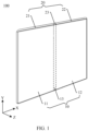
- FIG. 1 is a three-dimensional view of a foldable mobile phone 100 in an unfolded state according to some embodiments of this application.
- the foldable mobile phone 100 in the unfolded state is approximately in a shape of a rectangular flat plate.
- an XYZ coordinate system is established for the foldable mobile phone 100 in the unfolded state.
- a length direction of the foldable mobile phone 100 is defined as an X-axis direction
- a width direction of the foldable mobile phone 100 is defined as a Y-axis direction
- a thickness direction of the foldable mobile phone 100 is defined as a Z-axis direction.
- a coordinate system of the foldable device 100 may be flexibly set based on an actual requirement, and is not specifically limited herein.
- the foldable mobile phone 100 may be alternatively in a shape of a square flat plate, a shape of a circular flat plate, a shape of an elliptical flat plate, or the like.
- the foldable mobile phone 100 includes a foldable screen 10 and a support apparatus 20.
- the foldable screen 10 is configured to display information such as an image or a video.
- the foldable screen 10 may be an organic light-emitting diode (organic light-emitting diode, OLED) screen, a micro organic light-emitting diode (micro organic light-emitting diode) screen, a quantum dot light emitting diode (quantum dot light emitting diodes, QLED) screen, a liquid crystal display (liquid crystal display, LCD), or the like.
- OLED organic light-emitting diode
- micro organic light-emitting diode micro organic light-emitting diode
- QLED quantum dot light emitting diode
- LCD liquid crystal display
- the foldable screen 10 has a display region used to display image information, and the display region of the foldable screen 10 is exposed, to present information such as an image or a video to a user.
- the foldable screen 10 includes a first display region 11, a second display region 12, and a third display region 13.
- the third display region 13 is connected between the first display region 11 and the second display region 12.
- the first display region 11, the third display region 13, and the second display region 12 are arranged in sequence in the X-axis direction. In this way, the foldable mobile phone 100 is horizontally folded.
- the first display region 11, the third display region 13, and the second display region 12 may be alternatively arranged in sequence in the Y-axis direction. In this way, the foldable mobile phone 100 is vertically folded.
- large-screen display can be implemented, to provide richer information for the user and bring better use experience to the user.
- At least the third display region 13 of the foldable screen 10 is in a structure of a flexible screen.
- the third display region 13 may be bent and deformed under external force, so that the foldable screen 10 is folded from the unfolded state shown in FIG. 1 to a folded state.
- the first display region 11 and the second display region 12 of the foldable screen 10 each may be in the structure of a flexible screen, or may be in a structure of a hard screen, or may be partially in the structure of a flexible screen and partially in the structure of a hard screen. This is not specifically limited herein.
- the support apparatus 20 is configured to bear the foldable screen 10.
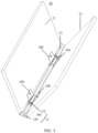
- FIG. 2 and FIG. 3 are respectively schematic diagrams of the support apparatus 20 at different folding angles.
- the support apparatus 20 includes a first housing 21, a second housing 22, and a rotating shaft mechanism 23.
- the first housing 21 bears the first display region 11, and the second housing 22 bears the second display region 12.
- the rotating shaft mechanism 23 is connected between the first housing 21 and the second housing 22, and bears the third display region 13.
- the rotating shaft mechanism 23 is configured to implement switching of an angle between the second housing 22 and the first housing 21, to support switching of the foldable screen 10 between the unfolded state and the folded state. It may be understood that there may be a plurality of groups of rotating shaft mechanisms 23.
- the plurality of groups of rotating shaft mechanisms 23 may be connected between the first housing 21 and the second housing 22.
- the first housing 21 and the second housing 22 may each include a middle frame (not shown in the figure) and a back cover (not shown in the figure) that are connected to each other.
- An accommodating cavity is formed between the middle frame and the back cover, and the accommodating cavity is used to accommodate electronic components such as a mainboard, a camera module, and a battery.
- the first housing 21 and the second housing 22 may be connected to the rotating shaft mechanism 23 by using the middle frame, or may be connected to the rotating shaft mechanism 23 by using the back cover.
- the rotating shaft mechanism 23 may include a rotating shaft base 110 and a shaft cover assembly 120. It may be understood that there may be a plurality of rotating shaft mechanisms 23 in one foldable mobile phone 100. The plurality of rotating shaft mechanisms 23 may share one shaft cover assembly 120. Structures of the plurality of rotating shaft mechanisms 23 may be the same. One rotating shaft mechanism 23 is described below.
- the rotating shaft base 110 may be configured to support the third display region 13 of the foldable screen 10.
- the first housing 21 and the second housing 22 may rotate around the rotating shaft base 110.
- the front surface may be used to bear the foldable screen 10.
- the shaft cover assembly 120 may be used as a protection mechanism for the rotating shaft mechanism 23.
- the shaft cover assembly 120 may be configured to cover the rotating shaft base 110 in the rotating shaft mechanism 23 and a moving component (not shown in the figure) connected to the rotating shaft base 110.
- the shaft cover assembly 120 may be disposed on the back surface of the rotating shaft base 110.
- the rotating shaft mechanism 23 may further include a swing arm 300.
- One swing arm 300 may be disposed at each of two ends of each rotating shaft base 110.
- Two swing arms 300 may rotate relative to the rotating shaft base 110.
- the two swing arms 300 may rotate by using the rotating shaft base 110 as an axis.
- the first housing 21 and the second housing 22 may be respectively fastened to the two swing arms 300.
- a manner of respectively fastening the two swing arms 300 to the first housing 21 and the second housing 22 is not limited, provided that the first housing 21 can be fastened relative to the swing arm 300.
- the swing arm 300 and the first housing 21 may be fastened by using a screw.
- the first housing 21 and the second housing 22 can rotate relative to the rotating shaft base 110, so that the foldable mobile phone 100 moves between the unfolded state and the folded state. It may be understood that, in some embodiments, the rotating shaft mechanism 23 may alternatively not need the swing arm 300.
- the first housing 21 and the second housing 22 are directly rotatably disposed on the rotating shaft base 110.
- the third display region 13 is folded into a water drop form.
- the third display region 13 includes an arc segment 133, a first transition segment 131, and a second transition segment 132.
- the first transition segment 131 is connected between the arc segment 133 and the first display region 11.
- the second transition segment 132 is connected between the arc segment 133 and the second display region 12.
- a distance between an end that is of the first transition segment 131 and that is connected to the first display region 11 and an end that is of the second transition segment 132 and that is connected to the second display region 12 is n
- a distance between an end that is of the first transition segment 131 and that is connected to the arc segment 133 and an end that is of the second transition segment 132 and that is connected to the arc segment 133 is m
- n is greater than m.
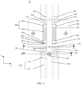
- FIG. 5 is a schematic diagram of an unfolded state of the rotating shaft mechanism 23.
- FIG. 6 is a schematic diagram of a specific angle in a process in which the rotating shaft mechanism 23 switches from the unfolded state to the folded state.
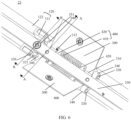
- FIG. 7 is an exploded view of the rotating shaft mechanism 23 shown in FIG. 5 and FIG. 6 .
- each swing arm 300 there may be two first connecting sleeves 310.
- the two first connecting sleeves 310 may be coaxially disposed at an interval.
- the first connecting sleeve 310 and the swing arm 300 may be fixedly disposed relative to each other.
- the first connecting sleeve 310 may be fastened to the swing arm 300 in a welding or bonding manner.
- the first connecting sleeve 310 and the swing arm 300 may be alternatively formed integrally.
- the rotating shaft base 110 may include a support plate 350 and a second connecting sleeve 340.
- the support plate 350 may be configured to support the third display region 13 (as shown in FIG. 1 ) of the foldable screen 10 (as shown in FIG. 1 ).
- Every two second connecting sleeves 340 may be connected by using one connecting plate 352.
- One second connecting sleeve 340 may be fixedly disposed at each of two ends of each connecting plate 352.
- two second connecting sleeves 340 and one connecting plate 352 may form one connecting sleeve assembly.
- the second connecting sleeve 340 may be fastened to the connecting plate 352 in a welding or bonding manner.
- a width of the connecting plate 352 may be slightly greater than a width of the support plate 350, and the support plate 350 may be bridged across a surface of the connecting plate 352.
- the connecting plate 352 and the support plate 350 may be stacked.
- second connecting sleeves 340 at both ends of the connecting plate 352 are also located on both sides of the support plate 350.
- the two second connecting sleeves 340 may be symmetrically fastened on both sides of the support plate 350.
- the connecting plate 352 and the support plate 350 may be fixedly connected relative to each other.
- the connecting plate 352 and the support plate 350 may be fixedly connected by using a bolt.
- the connecting plate 352 and the support plate 350 may be alternatively welded, riveted, or bonded.
- the connecting plate 352 and the support plate 350 may be alternatively formed integrally.
- the second connecting sleeve 340 may be alternatively directly fastened to two opposite sides of the support plate 350.
- the second connecting sleeve 340 and the support plate 350 may be formed integrally.
- the second connecting sleeve 340 may be alternatively fastened to the support plate 350 by using a mechanical structure or a welding process.
- the second connecting sleeve 340 may be fastened to the support plate 350 by a screw.
- the rotating shaft mechanism 23 may further include two rotating shafts 320.
- the rotating shaft 320 may extend in the Y direction.
- Each rotating shaft 320 may pass through two first connecting sleeves 310 and two second connecting sleeves 340.
- the two first connecting sleeves 310 may be located between the two second connecting sleeves 340.
- One connecting plate 352 may be disposed at each of two ends of the rotating shaft mechanism 23 in the Y direction. A length direction of the connecting plate 352 may be consistent with the X direction. Second connecting sleeves 340 at both ends of each connecting plate 352 may separately pass through one rotating shaft 320.
- Two swing arms 300 are respectively fixedly disposed on one rotating shaft 320 relative to each other by using the first connecting sleeve 310, and the rotating shaft 320 can rotate relative to the second connecting sleeve 340. Therefore, the two swing arms 300 can be rotatably disposed relative to the rotating shaft base 110.
- the two second connecting sleeves 340 are disposed at two ends of the rotating shaft 320, and may serve to limit the two first connecting sleeves 310, to prevent the swing arm 300 from slipping off the rotating shaft 320.
- the rotating shaft 320 may be fixedly connected to the first connecting sleeve 310. In other words, the rotating shaft 320 and the first connecting sleeve 310 do not rotate relative to each other. When rotating, the first connecting sleeve 310 can drive the rotating shaft 320 to rotate.
- the rotating shaft 320 may be rotatably connected to the second connecting sleeve 340. In other words, the rotating shaft 320 may rotate freely in the second connecting sleeve 340. Rotation herein means that the rotating shaft 320 can self-rotate around an axis of the rotating shaft 320.
- the swing arm 300 can drive the first connecting sleeve 310 to rotate.
- the first connecting sleeve 310 is fixedly connected to the rotating shaft 320 through rotation, and therefore, the first connecting sleeve 310 can drive the rotating shaft 320 to self-rotate.
- the rotating shaft 320 fits the second connecting sleeve 340 through rotation, and the second connecting sleeve 340 is fixedly disposed relative to the support plate 350. Therefore, the rotating shaft 320 can rotate relative to the support plate 350.
- the rotating shaft 320 may have a limiting segment 322, and a flat position 324 may be formed on a surface of the limiting segment 322. Through the flat position 324, the rotating shaft 320 can be prevented from rotating relative to the first connecting sleeve 310 in the first connecting sleeve 310, so that the rotating shaft 320 is fixedly disposed with the first connecting sleeve 310.
- FIG. 9 is a cross-sectional view at a position A-A in FIG. 5 and FIG. 6 .
- a shape of an inner wall of the first connecting sleeve 310 may match a shape of a surface of the limiting segment 322.
- a contour of a cross-section of the limiting segment 322 is basically the same as a shape of a cross-section that is of the first connecting sleeve 310 and that correspondingly accommodates the limiting segment 322.
- Another portion of the rotating shaft 320 except a segment of the flat position 324 may be cylindrical.
- the swing arm 300 drives the first connecting sleeve 310.
- the first connecting sleeve 310 drives, by using the flat position 324, the rotating shaft 320 to self-rotate. Therefore, the swing arm 300 can swing relative to the rotating shaft base 110.
- the rotating shaft 320 may be in interference fit with the first connecting sleeve 310, so that the rotating shaft 320 and the first connecting sleeve 310 are fastened to each other.
- the swing arm 300 may be fastened to the rotating shaft 320 in a welding manner.
- the swing arm 300 may be alternatively fastened to the rotating shaft 320 in a mechanical connection manner such as riveting or a screw connection.
- the rotating shaft mechanism 23 further includes a damping mechanism 400.
- the damping mechanism 400 may include an elastic member 410 and a first cam 420. Specifically, one elastic member 410 and two first cams 420 are configured for each rotating shaft 320. The elastic member 410 may be disposed between the two first cams 420. For each rotating shaft 320, the first connecting sleeve 310, the first cam 420, the elastic member 410, the first cam 420, and the first connecting sleeve 310 are arranged in sequence in an axis direction of the rotating shaft 320.
- a second cam 312 is disposed at an end that is of each first connecting sleeve 310 and that faces the first cam 420.
- the first cam 420 may have a first convex part 421 and a first concave part 422.
- the second cam 312 has a second convex part 313 and a second concave part 314, separately.
- the second convex part 313 of the second cam 312 gradually slides from the first concave part 422 of the first cam 420 to the first convex part 421 of the first cam 420.
- the second convex part 313 of the second cam 312 gradually abuts against the first convex part 421 of the first cam 420, and therefore, the second cam 312 squeezes the elastic member 410 by using the first cam 420.
- resistance caused by the elastic member 410 is experienced, so that hand feel is improved.
- the elastic member 410 may be a spring.
- the spring may be sleeved on the rotating shaft 320.
- a centrifugal part 330 may be disposed at an end part of the rotating shaft 320.
- the centrifugal part 330 is centrifugal relative to the axis of the rotating shaft 320.
- the centrifugal part 330 rotates around the axis of the rotating shaft 320. It may be understood that, when the rotating shaft 320 rotates, the centrifugal part 330 may have a displacement component in the thickness direction of the rotating shaft base 110.
- the centrifugal part 330 has a highest point and a lowest point in the thickness direction of the rotating shaft base 110.
- a distance between the highest point and the lowest point may be a maximum displacement difference of the centrifugal part 330 in the thickness direction of the rotating shaft base 110.
- FIG. 10 and FIG. 11 are cross-sectional views at a position B-B in FIG. 5 and FIG. 6 .
- the shaft cover assembly 120 may include a shaft cover 122 and a lifting/lowering block 121.
- the shaft cover 122 and the lifting/lowering block 121 may be fixedly disposed relative to each other.
- the lifting/lowering block 121 may be located on the back surface of the rotating shaft base 110 (as shown in FIG. 3 ).
- the shaft cover 122 is disposed on a side that is of the lifting/lowering block 121 and that is away from the rotating shaft base 110.
- the lifting/lowering block 121 is located between the rotating shaft base 110 and the shaft cover 122.
- a form of fastening the shaft cover 122 and the lifting/lowering block 121 is not limited.
- a form of welding, riveting, or the like may be used between the shaft cover 122 and the lifting/lowering block 121.
- the shaft cover 122 and the lifting/lowering block 121 may be alternatively fastened by using a common mechanical connection, such as clamping or a threaded connection.
- An accommodating groove 500 may be disposed on a side wall of the lifting/lowering block 121.
- the centrifugal part 330 may be inserted into the accommodating groove 500 in an axial direction of the rotating shaft 320.
- the centrifugal part 330 may be a centrifugal post. Refer to FIG. 8 .
- the centrifugal post may be connected to the rotating shaft 320 by using a connecting arm 321.
- the connecting arm 321 may be separately perpendicular to the centrifugal post and the rotating shaft 320.
- the centrifugal post may be rotatably disposed in the accommodating groove 500.
- the centrifugal part 330 is in clearance fit with the accommodating groove 500; in other words, a cross-sectional area of the centrifugal part 330 may be less than a cross-sectional area of the accommodating groove 500. There is space for the centrifugal part 330 to rotate and move in the accommodating groove 500.
- a diameter of the centrifugal post may be less than a width of the accommodating groove 500 in the X direction.
- a height of an inner wall of the accommodating groove 500 in the thickness direction of the rotating shaft base 110 is less than a maximum displacement difference of the centrifugal part 330 in the thickness direction of the rotating shaft base 110 in one rotation period. Therefore, in the thickness direction of the rotating shaft base 110, when rotating, the centrifugal part 330 can drive the shaft cover assembly 120 to move in the thickness direction of the rotating shaft base 110.
- the rotating shaft mechanism 23 may further include a guide mechanism 560.
- the guide mechanism 560 may be disposed between the shaft cover assembly 120 and the rotating shaft base 110.
- the guide mechanism 560 may include a guide post 561.
- a second guide hole 353 is disposed on the lifting/lowering block 121.
- the rotating shaft base 110 has a first guide hole 351 that is disposed in the thickness direction of the rotating shaft base 110.
- the first guide hole 351 may be disposed on the support plate 350.
- the first guide hole 351 and the second guide hole 353 are disposed coaxially, and the guide post 561 penetrates the first guide hole 351 and the second guide hole 353.
- the guide post 561 passes through the first guide hole 351 and the second guide hole 353.
- the guide post 561 may be a screw.
- a threaded groove 583 may be disposed on a surface that is of the shaft cover 122 and that faces the rotating shaft base.
- the screw may pass through the first guide hole 351 disposed on the support plate 350 and the second guide hole 353 disposed on the lifting/lowering block 381, and then is inserted into the threaded groove 583 to fit the threaded groove 583.
- the screw is relatively fastened to the shaft cover 122 and the lifting/lowering block 121 by using the threaded groove 583.
- a diameter of the first guide hole 351 may be slightly greater than a diameter of the screw.
- the first guide hole 351 may be in clearance fit with the screw, so that the screw can move in an axial direction of the first guide hole 351.
- the first guide hole 351 may have a constraining effect on movement of the screw.
- the first guide hole 351 may limit the screw to move in the thickness direction of the rotating shaft base, to prevent the screw from swinging in the X direction.
- the threaded groove 583 may be formed in a cylindrical protrusion 584 on a surface of the shaft cover 122.
- a diameter of the cylindrical protrusion 584 may be less than a diameter of the second guide hole 353. Therefore, the cylindrical protrusion 584 may pass through the second guide hole 353 to be close to the first guide hole 351.
- the first guide hole 351 can also have a limiting effect on movement of the cylindrical protrusion 584, to prevent the first guide hole 351 from swinging in the X direction.
- a height of the inner wall of the accommodating groove 500 in the thickness direction of the rotating shaft base 110 is less than the maximum displacement difference of the centrifugal part 330 in the thickness direction of the rotating shaft base 110 (as shown in FIG. 3 ) in one rotation period. Therefore, in the thickness direction of the rotating shaft base 110, when rotating, the centrifugal part 330 is in contact with the inner wall of the accommodating groove 500 in the Z direction, so that the shaft cover assembly 120 can be driven to move in the thickness direction of the rotating shaft base 110.
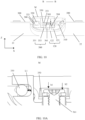
- FIG. 10A is an enlarged view of FIG. 10 at a position M
- FIG. 11A is an enlarged view of FIG. 11 at a position N.
- a relative height of a top part b2 (a surface that is of the guide post 561 and that is away from the shaft cover 122 in the Z direction) of the guide post 561 and a relative height of a top part b 1 (a surface that is of the support plate 350 and that is away from the shaft cover 122 in the Z direction) of the support plate 350 in a pose in FIG. 10 are different from those in a pose in FIG. 11 .
- the top part b2 of the guide post 561 When the swing arm 300 is in the unfolded state, the top part b2 of the guide post 561 is lower than the top part b 1 of the support plate 350. When the swing arm 300 is folded to a specific angle, the top part b2 of the guide post 561 exceeds the top part b1 of the support plate 350. In other words, when the swing arm 300 is being switched from the unfolded state to the folded state, the shaft cover assembly 120 may move in a direction approaching the rotating shaft base 110; and when the swing arm 300 is being switched from the folded state to the unfolded state, the shaft cover assembly 120 may move in a direction away from the rotating shaft base 110.
- the shaft cover assembly 120 is closer to the rotating shaft base 110 when the swing arm 300 is in the folded state.
- the shaft cover assembly 120 approaches the rotating shaft base 110 when being folded, so that a gap between the shaft cover assembly 120 and the rotating shaft base 110 can be reduced, and a risk that the rotating shaft base 110 and a component connected to the rotating shaft base 110 are exposed can be avoided to some extent.
- the connecting arm 321 may be enabled to rotate by 2 ⁇ (90°-a) on the basis of the angle a in an anti-clockwise direction shown in the figure, and a position of the centrifugal post at this angle is used as an initial position from which the swing arm 300 is switched from the unfolded state to the folded state.
- the shaft cover assembly 120 may move in a direction away from the rotating shaft base 110.
- the shaft cover assembly 120 may move in a direction approaching the rotating shaft base 110, and may provide, in the folded state, larger space between the rotating shaft base 110 and the shaft cover assembly 120.
- a distance between the centrifugal post and the inner wall of the accommodating groove 500 may be a second distance L2, and the second distance L2 may be less than the first distance L1.
- the centrifugal post rolls in the accommodating groove 500. Due to a gap between the centrifugal post and the inner wall of the accommodating groove 500, the centrifugal post may collide with the inner wall of the accommodating groove 500 due to shaking in a rolling process, and consequently, abnormal sound is caused.
- the rotating shaft mechanism 23 in this embodiment of this application may include a limiting member. At least a portion of the limiting member may be located in the accommodating groove 500. Alternatively, the limiting member may be entirely disposed in the accommodating groove 500.
- the limiting member may be configured to adjust the gap between the centrifugal part 330 and the inner wall of the accommodating groove 500, so that shaking of the limiting member in the accommodating groove 500 can be limited, and hard friction between the centrifugal part 330 and the inner wall of the accommodating groove 500 can be reduced, thereby reducing abnormal sound. If the gap between the centrifugal part 330 and the inner wall of the accommodating groove 500 is reduced by using the limiting member, a requirement on processing precision of the accommodating groove 500 and the centrifugal part 330 can also be reduced, and costs are effectively reduced.
- Hardness of a material of the limiting member may be less than hardness of the inner wall of the accommodating groove 500 and the centrifugal part 330, and the limiting member may achieve a buffering effect between the accommodating groove 500 and the centrifugal part 330.
- the limiting member may be a block structure or a layered structure.
- a shape of the limiting member may alternatively match a shape of the inner wall of the accommodating groove 500, or the shape of the limiting member may match a shape of the centrifugal post.
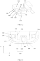
- a limiting member 570 includes a first limiting layer 572.
- FIG. 12 is an exploded view in which the lifting/lowering block 121 fits the first limiting layer 572.
- FIG. 13 is a side cross-sectional view in which the lifting/lowering block 121 fits the first limiting layer 572 in FIG. 12 .
- the accommodating groove 500 may include a bottom plate 550, a first side plate 510, a second side plate 520, and a fourth side plate 540.
- the bottom plate 550, the first side plate 510, the second side plate 520, and the fourth side plate 540 may enclose to form the accommodating groove 500.
- the first side plate 510, the second side plate 520, and the fourth side plate 540 respectively extend along the axis of the rotating shaft 320 (as shown in FIG. 7 ). End parts of the first side plate 510, the second side plate 520, and the fourth side plate 540 separately abut against the bottom plate 550.
- the bottom plate 550 may be perpendicular to the axis of the rotating shaft 320.
- a plane on which the first side plate 510 is located may be perpendicular to a plane on which the second side plate 520 is located.
- the fourth side plate 540 may be disposed close to the shaft cover 122.
- the fourth side plate 540 may be parallel to the first side plate 510.
- the bottom plate 550, the first side plate 510, the second side plate 520, and the fourth side plate 540 may be formed by splicing mechanical structures, or may be formed integrally.
- the centrifugal part 330 may enter the accommodating groove 500 through the inlet 501.
- Surfaces that are of the first side plate 510, the second side plate 520, and the fourth side plate 540 and that face an interior of the accommodating groove 500 may constitute a side wall of the accommodating groove 500.
- a surface that is of the bottom plate 550 and that faces the interior of the accommodating groove 500 forms a bottom wall of the accommodating groove 500.
- That the bottom plate 550 is opposite to the inlet 501 may be understood as that the bottom wall of the accommodating groove 500 is opposite to the inlet 501.
- the bottom wall of the accommodating groove 500 and the side wall of the accommodating groove 500 may constitute the inner wall of the accommodating groove 500.
- the first limiting layer 572 may be located on the side wall of the accommodating groove 500. Specifically, the first limiting layer 572 may be fastened on a surface that is of the fourth side plate 540 and that faces the interior of the accommodating groove 500. The fourth side plate 540 may be closer to the shaft cover 122 than the first side plate 510. The first limiting layer 572 may extend in a depth direction (the Y direction) of the accommodating groove 500. A side wall of the centrifugal post may be in contact with a surface of the first limiting layer 572. The first limiting layer 572 may be fastened to the side wall of the accommodating groove 500 in a bonding or welding manner. The first limiting layer 572 can fill the gap between the accommodating groove 500 and the centrifugal post in the Z direction, to reduce collision between the centrifugal post and the side wall of the accommodating groove 500 in the Z direction.
- the first limiting layer 572 may be disposed at any position on the inner wall of the accommodating groove 500, provided that the first limiting layer 572 can be located between the centrifugal part 330 and the inner wall of the accommodating groove 500 to reduce abnormal sound.
- the first limiting layer 572 may be in interference fit with the centrifugal post.
- the first limiting layer 572 may provide resistance for rotation of the centrifugal post. Therefore, a damping effect can be implemented, and hand feel of opening/closing during an operation of the user is improved.
- the first limiting layer 572 may be a plate-shape structure, and a thickness of the first limiting layer 572 may be set as required.
- a third limiting groove 573 may be formed on a surface that is of the first limiting layer 572 and that faces the inner wall of the accommodating groove 500.
- the third limiting groove 573 extends in a direction in which the rotating shaft 320 extends.
- the side wall of the centrifugal post may be embedded into the third limiting groove 573 to reduce a degree of shaking of the centrifugal post.
- a material of the first limiting layer 572 may be a material with specific flexibility such as rubber or a metal sheet.
- the first limiting layer 572 may be fastened to the side wall of the accommodating groove 500 in a bonding or welding manner.
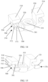
- FIG. 15 is an exploded view in which the lifting/lowering block 121 fits the first limiting layer 572.
- FIG. 16 is a side cross-sectional view in which the lifting/lowering block 121 fits the first limiting layer 572 in FIG. 15 .
- the first limiting layer 572 may be located on the bottom wall of the accommodating groove 500.
- the first limiting layer 572 may cover the bottom wall of the accommodating groove 500.
- An end part of the centrifugal post may abut against the bottom wall of the accommodating groove 500. Therefore, the first limiting layer 572 can prevent the centrifugal post from shaking in the axial direction of the rotating shaft 320.
- the end part of the centrifugal post may abut against the surface of the first limiting layer 572.
- the end part of the centrifugal post abuts against the first limiting layer 572, the end part of the centrifugal post can be prevented from directly colliding with a bottom part of the accommodating groove 500 due to shaking, thereby reducing abnormal sound.
- a damping effect can also be achieved for rotation of the centrifugal post.
- a limiting step 512 is disposed on the bottom wall of the accommodating groove 500.
- the limiting step 512 may extend in the X direction on a surface of the bottom plate 550.
- a quantity of limiting steps 512 is not limited.
- the two limiting steps 512 when there are two limiting steps 512, the two limiting steps 512 may be respectively disposed on two opposite edges of the bottom wall of the accommodating groove 500, and respectively abut against the side wall of the accommodating groove 500. Space between the two limiting steps may be used to limit the first limiting layer 572 to prevent the first limiting layer 572 from detaching from the bottom wall of the accommodating groove 500.
- the first limiting layer 572 is sandwiched between the limiting step 512 and the side wall of the accommodating groove 500.
- the limiting step 512 may be located on an edge of the bottom wall of the accommodating groove 500. Space may be formed between the limiting step 512 and the side wall of the accommodating groove 500, and the first limiting layer 572 may be accommodated in the space, to prevent the first limiting layer 572 from shaking in the accommodating groove 500.
- the limiting step 512 may be formed integrally with the inner wall of the accommodating groove 500.
- the limiting step 512 may be alternatively fastened to the inner wall of the accommodating groove 500 as a separate part.
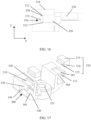
- FIG. 17 is an exploded view of the lifting/lowering block 121 and the limiting member 570 in an embodiment.
- FIG. 18 is a schematic cross-sectional view in which the lifting/lowering block 121 fits the limiting member 570 in FIG. 17 .
- the limiting member 570 may further include a second limiting layer 575 and a connecting part 576.
- the second limiting layer 575 may be located on an outer wall of the lifting/lowering block 121.
- the second limiting layer 575 may be fastened to the outer wall of the lifting/lowering block 121 in a bonding or embedding manner.
- the first limiting layer 572 may be located on the inner wall of the accommodating groove 500.
- the first limiting layer 572 may be connected to the second limiting layer 575 by using the connecting part 576.
- the connecting part 576 may connect, in a bent state, the first limiting layer 572 and the second limiting layer 575.
- Projections of the first limiting layer 572 and the second limiting layer 575 on the inner wall of the accommodating groove 500 may have an overlapping portion, or may have no overlapping portion.
- the second limiting layer 575 may play a binding role on the first limiting layer 572 to prevent the first limiting layer 572 from detaching from the inner wall of the accommodating groove 500. In other words, when the centrifugal post rotates, the first limiting layer 572 does not easily detach from the interior of the accommodating groove 500.
- the connecting part 576 may be a flexible material such as polyester, or may be a flexible metal material.
- the connecting part 576 may be a layered structure, or may be a columnar structure that can be bent. Both ends of the columnar structure may be respectively connected to the first limiting layer 572 and the second limiting layer 575.
- the connecting part 576 may be alternatively embedded into the outer wall of the lifting/lowering block 121, to prevent detachment of the connecting part 576.
- the first limiting layer 572, the second limiting layer 575, and the connecting part 576 may be formed integrally.
- a flat plate structure is formed.
- the first limiting layer 572, the second limiting layer 575, and the connecting part 576 may be U-shaped after being molded.
- the first limiting layer 572 and the second limiting layer 575 may be separately bonded between the inner wall of the accommodating groove 500 and the outer wall of the lifting/lowering block 121. It may be understood that the outer wall of the lifting/lowering block 121 and the outer wall of the accommodating groove 500 are a same surface.
- the first limiting layer 572, the connecting part 576, and the second limiting layer 575 may be formed on the lifting/lowering block 121 in an injection molding manner.
- Materials of the first limiting layer 572, the connecting part 576, and the second limiting layer 575 may be rubber, for example, a polyester material such as rubber, or may be a polycarbonate (PC) material.
- a protruding structure 574 may be alternatively fabricated by using a mold.
- the accommodating groove 500 may further include a third side plate 530 in addition to the first side plate 510, the second side plate 520, and the fourth side plate 540.
- the plane on which the first side plate 510 is located may be perpendicular to the thickness direction of the rotating shaft base 110 (as shown in FIG. 3 ).
- the second side plate 520 and the third side plate 530 may be respectively located at two opposite ends of the first side plate 510.
- the plane on which the second side plate 520 is located and a plane on which the third side plate 530 is located may extend along the axis of the rotating shaft 320. In other words, the second side plate 520 and the third side plate 530 may be parallel to the axis of the rotating shaft 320.
- the second side plate 520 and the third side plate 530 may be parallel to the Z direction. Two opposite ends of the first side plate 510 may respectively abut against two opposite surfaces of the second side plate 520 and the third side plate 530.
- the first side plate 510, the second side plate 520, and the third side plate 530 enclose to form a second limiting groove 582.
- the first side plate 510, the second side plate 520, and the third side plate 530 enclose to form a portion of the accommodating groove 500.
- the second limiting layer 575 may be located in the second limiting groove 582.
- the second limiting layer 575 may be embedded into the second limiting groove 582 to prevent the second limiting layer 575 from detaching from a surface of the lifting/lowering block 121.
- the second limiting groove 582 may be alternatively a concave structure formed on the surface of the lifting/lowering block 121.
- the second limiting layer 575 may be embedded into the second limiting groove 582.
- a shape of the second limiting groove 582 may match a shape of the second limiting layer 575.
- the second limiting layer 575 may be in a shape such as a rectangle, an oval, a cone, or a circle.
- a depth of the second limiting groove 582 may be the same as a thickness of the second limiting layer 575. Alternatively, the depth of the second limiting groove 582 may be slightly greater than the thickness of the second limiting layer 575.
- the first side plate 510, the second side plate 520, and the third side plate 530 enclose the inner wall of the accommodating groove 500 to form a first limiting groove 584.
- surfaces that are of the first side plate 510, the second side plate 520, and the third side plate 530 and that face the interior of the accommodating groove 500 enclose to form the first limiting groove 584.
- the first limiting layer 572 is located in the first limiting groove 584.
- the second limiting groove 582 and the first limiting groove 584 may be respectively located on two sides of the first side plate 510. It may be understood that the first limiting groove 584 may be a portion of the accommodating groove 500.
- a shape of the first limiting groove 584 may match a shape of the first limiting layer 572, and therefore, the first limiting layer 572 can be prevented from shaking in the accommodating groove 500. Further, a distance between the second side plate 520 and the third side plate 530 may be the same as a width of the first limiting layer 572, to avoid shaking of the first limiting layer 572.
- a length of the second side plate 520 may be the same as a length of the third side plate 530, and a length of the first side plate 510 may be less than the length of the second side plate 520 and the length of the third side plate 530.
- the first side plate 510 is a short plate, and this is equivalent to that the first side plate 510 is recessed toward the bottom plate 550 to form a limiting port 511.
- the connecting part 576 may be laid on the limiting port 511 and connect the first limiting layer 572 to the second limiting layer 575. It may be understood that the first side plate 510 may have a specific thickness, and the connecting part 576 may be coated on the first side plate 510 to form an end part of the limiting port 511.
- the limiting port 511 can also prevent the connecting part 576 from detaching from the limiting port 511.
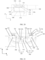
- FIG. 19 is an exploded view of the lifting/lowering block 121 and the limiting member 570 in an embodiment.
- FIG. 20 is a schematic diagram of a side cross-section in which the lifting/lowering block 121 fits the limiting member 570 in FIG. 19 .
- FIG. 21 is a schematic diagram of a front cross-section in which the lifting/lowering block 121 fits the limiting member in FIG. 19 .
- the materials of the first limiting layer 572, the second limiting layer 575, and the connecting part 576 are changed from rubber to metal.
- the first limiting layer 572, the second limiting layer 575, and the connecting part 576 may be stainless steel.
- the first limiting layer 572, the second limiting layer 575, and the connecting part 576 may be connected to each other to form a bent metal sheet structure.
- the first limiting layer 572 and the second limiting layer 575 may be two ends of the metal sheet structure.
- the connecting part 576 is a bent portion of the metal sheet structure.
- the metal sheet structure may have specific elasticity.
- the metal sheet structure may use a stainless steel material.
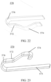
- FIG. 22 is a schematic diagram of the limiting member 570.
- a protruding structure 574 protruding toward the interior of the accommodating groove 500 is disposed at the first limiting layer 572, and the protruding structure 574 abuts against the side wall of the centrifugal post.
- the protruding structure 574 may have specific elasticity, and therefore can achieve a buffering effect for the centrifugal post when the centrifugal post is shaking.
- a quantity of protruding structures 574 may be set as required, for example, a plurality of protruding structures 574 that are disposed at intervals may be formed on the surface of the first limiting layer 572, so that a plurality of contact points can be formed for the first limiting layer 572 and the side wall of the centrifugal post, thereby improving contact stability.
- a manner of forming the protruding structure 574 is not limited.
- the protruding structure 574 may be formed by bending the first limiting layer 572.
- the protruding structure 574 may be formed in a stamping and bending manner.
- the protruding structure 574 is disposed on a middle portion of the first limiting layer 572.
- the protruding structure 574 may be not located at an end part of the first limiting layer 572. Both ends of the first limiting layer 572 respectively abut against a surface that is of the first side plate 510 and that faces the accommodating groove 500. When the protruding structure 574 is squeezed by the centrifugal post, force may be transferred to the first side plate 510 by using the end part of the first limiting layer 572.
- FIG. 23 is a schematic diagram of another embodiment of the limiting member 570.
- the protruding structure 574 is located at an end that is of the first limiting layer 572 and that is close to the bottom plate 550.
- the protruding structure 574 may achieve support and shaking buffering effects for the centrifugal post.
- an end part in the metal sheet structure may be bent to form the protruding structure 574.
- An end part of a metal sheet may form a folded structure that is supported on a surface of the first side plate 510, to enhance stability.
- FIG. 24 is a schematic diagram in which the limiting member 570 fits the lifting/lowering block 121 in another embodiment.
- the first limiting layer 572 may be located on a side that is of the fourth side plate 540 and that faces the interior of the accommodating groove 500
- the second limiting layer 575 may be located on a side that is of the fourth side plate 540 and that is away from the interior of the accommodating groove 500.
- the first limiting layer 572 and the second limiting layer 575 are clamped on two opposite surfaces of the fourth side plate 540 by using the connecting part 576.
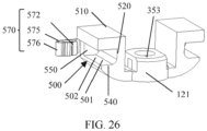
- FIG. 25 is a schematic diagram in which the limiting member 570 fits the lifting/lowering block 121 in another embodiment.
- FIG. 26 is an exploded view of the embodiment in FIG. 25 .
- the first limiting layer 572 is located on a surface that is of the bottom plate 550 and that faces the interior of the accommodating groove 500
- the second limiting layer 575 is located on a surface that is of the bottom plate 550 and that is away from the interior of the accommodating groove 500.
- the connecting part 576 is connected to the first limiting layer 572 and the second limiting layer 575 through an opening 502 located between the first side plate 510 and the fourth side plate 540.
- the second limiting layer 575 may be fastened to an outer wall of the bottom plate 550 in a manner of bonding, welding, or the like. Therefore, the first limiting layer 572 can be prevented from detaching from the bottom plate 550.
- the first limiting layer 572 can reduce collision caused by the end part of the centrifugal post to a bottom part of the accommodating groove 500, and can also bring damping to rotation of the centrifugal post, thereby improving hand feel of the user during use.
- the opening 502 formed between the first side plate 510 and the fourth side plate 540 may be set based on a size.
- the opening 502 between the first side plate 510 and the fourth side plate 540 may be opposite to the third side plate 530. Same ends of the first side plate 510 and the fourth side plate 540 abut against a surface that is of the second side plate 520 and that faces the interior of the accommodating groove 500.
- the other ends of the first side plate 510 and the fourth side plate 540 may be free ends and form the opening 502.
- the connecting part 576 may separately connect the first limiting layer 572 and the second limiting layer 575 by bypassing an end that is of the bottom plate 550 and that is away from the second side plate 520.
- the connecting part 576 may be embedded at the end that is of the bottom plate 550 and that is away from the second side plate 520, to enhance stability of fitting between the limiting member 570 and the lifting/lowering block 121.
- the lifting/lowering block 121 may be a symmetrical structure.
- two accommodating grooves 500 may be symmetrically disposed with respect to the second guide hole 353.
- the second guide hole 353 may be located on an axis of symmetry of the rotating shaft mechanism 23.
- the second side plate 520 may be disposed near the second guide hole 353.
- the opening 502 may be formed on a side that is of the second side plate 520 and that is away from the second guide hole 353.
- Each accommodating groove 500 may fit one limiting member 570. Because accommodating grooves 500 and limiting members 570 are the same in terms of structures and fitting relationships, details are not described herein again.
- perpendicular and parallel described in the embodiments of this application are not strict “perpendicular” and “parallel” in a mathematical sense, and “perpendicular” herein may be understood as a position relationship of being approximately perpendicular within a range of a manufacture error and an operation error.
Landscapes
- Engineering & Computer Science (AREA)
- General Engineering & Computer Science (AREA)
- Theoretical Computer Science (AREA)
- Computer Hardware Design (AREA)
- Signal Processing (AREA)
- Human Computer Interaction (AREA)
- Physics & Mathematics (AREA)
- General Physics & Mathematics (AREA)
- Mechanical Engineering (AREA)
- Microelectronics & Electronic Packaging (AREA)
- Telephone Set Structure (AREA)
Abstract
Description
- This application claims priority to
Chinese Patent Application No. 202210827273.8, filed with the China National Intellectual Property Administration on July 13, 2022 - This application relates to a rotating shaft mechanism and a foldable terminal device.
- A foldable terminal device has two poses: unfolded and folded. A rotating shaft mechanism is an important component for unfolding and folding the foldable terminal device. In a process in which the foldable terminal device is switched from an unfolded state to a folded state or from a folded state to an unfolded state, a transmission mechanism inside the rotating shaft mechanism is prone to a problem during transmission, and this not only affects user experience, but also shortens a service life of a part.
- Embodiments of this application provide a rotating shaft mechanism and a foldable terminal device, to resolve a problem of abnormal sound that is caused by collision between parts when the rotating shaft mechanism rotates.
- An embodiment of this application provides a rotating shaft mechanism, including a rotating shaft base, a shaft cover assembly, a rotating shaft, a centrifugal part, and a limiting member. The shaft cover assembly is disposed on a side of the rotating shaft base in a thickness direction of the rotating shaft base, and an accommodating groove is disposed in the shaft cover assembly. The rotating shaft is rotatably disposed on the rotating shaft base. The centrifugal part is fixedly disposed at one end of the rotating shaft, and the centrifugal part deviates from an axis of the rotating shaft. The centrifugal part is rotatably disposed in the accommodating groove and is in clearance fit with the accommodating groove. When the rotating shaft rotates, the rotating shaft drives, by using the centrifugal part, the shaft cover assembly to move in the thickness direction of the rotating shaft base. The limiting member is at least partially located in the accommodating groove. The limiting member is configured to abut against the centrifugal part in rotation.
- In this embodiment, when the rotating shaft rotates, the centrifugal part can be driven to rotate in the accommodating groove around the axis of the rotating shaft. Rotation of the centrifugal part can drive the shaft cover assembly to move in the thickness direction of the rotating shaft base. The limiting member is at least partially located in the accommodating groove, and can abut against the centrifugal part when the centrifugal part rotates. Therefore, when the centrifugal part rotates, the limiting member can fill at least a gap between the accommodating groove and the centrifugal part. When the centrifugal part rotates, the centrifugal part can limit rotation or displacement of the limiting member relative to an inner wall of the accommodating groove, thereby reducing abnormal sound.
- In an embodiment, the limiting member includes a first limiting layer, the first limiting layer is disposed on the inner wall of the accommodating groove, and the centrifugal part abuts against the first limiting layer.
- In this embodiment, the first limiting layer may be laid on the inner wall of the accommodating groove, and may occupy a relatively large area. Therefore, the centrifugal part may have a relatively large contact area with the inner wall of the accommodating groove, so that stability can be enhanced when the centrifugal part rotates in the accommodating groove.
- In an embodiment, the shaft cover assembly includes a lifting/lowering block and a shaft cover that are fixedly disposed relative to each other, the shaft cover is disposed on a side that is of the lifting/lowering block and that is away from the rotating shaft base, and the accommodating groove is disposed in the lifting/lowering block. Therefore, when the shaft cover assembly moves in the thickness direction of the rotating shaft base, the shaft cover is driven by the lifting/lowering block to move. The lifting/lowering block is used as a position for disposing the accommodating groove.
- In an embodiment, the limiting member further includes a second limiting layer and a connecting part, the second limiting layer is disposed on an outer wall of the lifting/lowering block, the inner wall of the accommodating groove is opposite to the outer wall of the lifting/lowering block, and the first limiting layer and the second limiting layer are connected by using the connecting part.
- In this embodiment, the first limiting layer and the second limiting layer are sandwiched between the inner wall of the accommodating groove and the outer wall of the lifting/lowering block, so that the first limiting layer can be prevented from detaching from the accommodating groove due to sliding friction when the centrifugal part rotates.
- In an embodiment, the lifting/lowering block includes a bottom plate and a first side plate. The bottom plate and the first side plate enclose to form at least a portion of the accommodating groove. An inlet of the accommodating groove is opposite to the bottom plate, and a plane on which the first side plate is located extends along the axis of the rotating shaft. The first limiting layer is located on a surface that is of the first side plate and that faces an interior of the accommodating groove, and the second limiting layer is located on a surface that is of the first side plate and that is away from the interior of the accommodating groove. The connecting part is connected to the first limiting layer and the second limiting layer through the inlet of the accommodating groove.
- In this embodiment, the first limiting layer and the second limiting layer are respectively clamped on two surfaces of the first side plate. The first limiting layer can abut against a side wall of the limiting member, to increase a contact area between the first limiting layer and the limiting member.
- In an embodiment, a protruding structure protruding toward the interior of the accommodating groove is disposed at the first limiting layer, and the protruding structure abuts against the centrifugal part.
- In this embodiment, the protruding structure may have specific elasticity, and therefore, a buffering effect can be achieved for a centrifugal post when the centrifugal post shakes.
- In an embodiment, the protruding structure is disposed on a middle portion of the first limiting layer. Two ends of the first limiting layer respectively abut against the surface that is of the first side plate and that faces the accommodating groove.
- In this embodiment, when the protruding structure is squeezed by the centrifugal post, force may be transferred to the first side plate by using two end parts of the first limiting layer.
- In an embodiment, the protruding structure is located at one end that is of the first limiting layer and that is close to the bottom plate.
- In this embodiment, the protruding structure is disposed at the end that is of the first limiting layer and that is close to the bottom plate, so that limitation on an end part of the limiting member can be enhanced, thereby avoiding collision between the limiting member and the bottom of the accommodating groove.
- In an embodiment, the lifting/lowering block includes a second side plate and a third side plate. Planes on which the second side plate and the third side plate are located extend along the axis of the rotating shaft, and are respectively located at two opposite ends of the first side plate. The bottom plate, the first side plate, the second side plate, and the third side plate enclose to form at least a portion of the accommodating groove. The first side plate, the second side plate, and the third side plate enclose the outer wall of the lifting/lowering block to form a first limiting groove, and the second limiting layer is located in the first limiting groove.
- In this embodiment, the first limiting groove is formed by using the bottom plate, the first side plate, the second side plate, and the third side plate. A structure is simple, and a position of the second limiting layer can be limited, to prevent the second limiting layer from detaching from the outer wall of the lifting/lowering block.
- In an embodiment, the first side plate, the second side plate, and the third side plate enclose the inner wall of the accommodating groove to form a second limiting groove, and the first limiting layer is located in the second limiting groove.
- In this embodiment, the second limiting groove is formed by using the bottom plate, the first side plate, the second side plate, and the third side plate. A structure is simple, and a position of the first limiting layer can be limited, to prevent the first limiting layer from detaching from the inner wall of the accommodating groove.
- In an embodiment, the lifting/lowering block includes a bottom plate, a first side plate, and a fourth side plate. An inlet of the accommodating groove is opposite to the bottom plate. A plane on which the first side plate is located and a plane on which the fourth side plate is located extend along the axis of the rotating shaft. The fourth side plate is opposite to the first side plate. The bottom plate, the first side plate, and the fourth side plate enclose to form at least a portion of the accommodating groove. The first limiting layer is located on a surface that is of the bottom plate and that faces an interior of the accommodating groove, and the second limiting layer is located on a surface that is of the bottom plate and that is away from the interior of the accommodating groove. The connecting part is connected to the first limiting layer and the second limiting layer through an opening located between the first side plate and the fourth side plate.
- In this embodiment, the first limiting layer and the second limiting layer are clamped on two sides of the bottom plate, and the second limiting layer is limited to a bottom wall of the accommodating groove, so that collision caused by the limiting member to the bottom wall of the accommodating groove can be reduced, and abnormal sound can be reduced.
- In an embodiment, the first limiting layer, the connecting part, and the second limiting layer are formed integrally. Overall strength of the limiting member is enhanced.
- In an embodiment, the first limiting layer, the connecting part, and the second limiting layer are metal sheets. Therefore, the limiting member has specific toughness and elasticity, and can implement a buffering effect for the centrifugal part, thereby avoiding damage to the centrifugal part that is caused by hard contact.
- In an embodiment, the first limiting layer, the second limiting layer, and the connecting layer are formed on the lifting/lowering block through injection molding. An injection molding manner is simple in process and low in costs, and can effectively match a size of the lifting/lowering block.
- In an embodiment, the inner wall of the accommodating groove includes a bottom wall and a side wall, the bottom wall of the accommodating groove is opposite to an inlet of the accommodating groove, and the side wall extends along the axis of the rotating shaft. The first limiting layer is disposed on the bottom wall of the accommodating groove.
- In an embodiment, two limiting steps are disposed at an interval on the bottom wall of the accommodating groove, and the first limiting layer is sandwiched between the two limiting steps. Space between the two limiting steps may be used to limit the first limiting
layer 572, to prevent the first limiting layer from detaching from the bottom wall of the accommodating groove. - In an embodiment, the inner wall of the accommodating groove includes a bottom wall and a side wall, the bottom wall of the accommodating groove is opposite to an inlet of the accommodating groove, the side wall extends along the axis of the rotating shaft, and the first limiting layer is disposed on the side wall.
- In an embodiment, a third limiting groove is disposed on a surface that is of the first limiting layer and that faces an interior of the accommodating groove, and the third limiting groove extends in a direction in which the rotating shaft extends. A side wall of the centrifugal part may be embedded into the third limiting groove, to reduce a degree of shaking of the centrifugal post.
- In an embodiment, the rotating shaft mechanism further includes a guide mechanism. The guide mechanism is disposed between the shaft cover assembly and the rotating shaft base. The guide mechanism is configured to constrain the shaft cover assembly to move in the thickness direction of the rotating shaft base. Therefore, when the centrifugal part rotates, the rotating shaft assembly can be prevented from shaking from side to side, and the rotating shaft assembly can be limited to move in a vertical direction.
- In an embodiment, a first guide hole is disposed on the rotating shaft base in the thickness direction of the rotating shaft base, a second guide hole is disposed on the lifting/lowering block, the first guide hole and the second guide hole are coaxially disposed, and a guide post penetrates the first guide hole and the second guide hole.
- In an embodiment, the centrifugal part includes a centrifugal post, and the centrifugal post is fixedly disposed at one end of the rotating shaft. An axis of the centrifugal post is parallel to the axis of the rotating shaft, and a width of the accommodating groove is greater than a diameter of the centrifugal post. A width direction of the accommodating groove is separately perpendicular to the axis of the rotating shaft and the thickness direction of the rotating shaft base, and the axis of the rotating shaft is perpendicular to the thickness direction of the rotating shaft base.
- When the centrifugal post rotates around the axis of the rotating shaft, a maximum displacement difference of the centrifugal post in the thickness direction of the rotating shaft base is a first distance, a height of the accommodating groove in the thickness direction of the rotating shaft base is a second distance, and the first distance is greater than the second distance.
- In an embodiment, the rotating shaft mechanism further includes a swing arm, and the swing arm is fixedly connected to the rotating shaft.
- An embodiment of this application further provides a rotating shaft mechanism. A rotating shaft base includes a rotating shaft base, a shaft cover assembly, a rotating shaft, and a centrifugal post. The shaft cover assembly is disposed on a side of the rotating shaft base in a thickness direction of the rotating shaft base, and an accommodating groove is disposed in the shaft cover assembly. The rotating shaft is rotatably disposed on the rotating shaft base. An axis of the rotating shaft is perpendicular to the thickness direction of the rotating shaft base. The centrifugal post is fixedly disposed at one end of the rotating shaft. An axis of the centrifugal post is parallel to the axis of the rotating shaft, a width of the accommodating groove is greater than a diameter of the centrifugal post, and a width direction of the accommodating groove is separately perpendicular to the axis of the rotating shaft and the thickness direction of the rotating shaft base. When the centrifugal post rotates around the axis of the rotating shaft, a maximum displacement difference of the centrifugal post in the thickness direction of the rotating shaft base is a first distance, a height of the accommodating groove in the thickness direction of the rotating shaft base is a second distance, and the first distance is greater than the second distance. A limiting member is at least partially located in the accommodating groove, and the limiting member is configured to abut against the centrifugal post in rotation.
- In this embodiment, the maximum displacement difference of the centrifugal post in the thickness direction of the rotating shaft base is the first distance, the height of the accommodating groove in the thickness direction of the rotating shaft base is the second distance, the first distance is greater than the second distance, and the width of the accommodating groove is greater than the diameter of the centrifugal post. Therefore, there is space for the centrifugal post to move from side to side during rotation, and in addition, the centrifugal post can come into contact with a side wall of the accommodating groove in the thickness direction of the rotating shaft base, so that the shaft cover assembly can be driven to move up and down. In a process in which the centrifugal part rotates and moves, the limiting member can fill at least a gap between the accommodating groove and a centrifugal part. When the centrifugal part rotates, the centrifugal part can limit rotation or displacement of the limiting member relative to an inner wall of the accommodating groove, thereby reducing abnormal sound.
- An embodiment of this application further provides a foldable terminal device, including the rotating shaft mechanism in the foregoing embodiment.
-
-
FIG. 1 is a schematic diagram of a flattened foldable terminal device according to some embodiments of this application; -
FIG. 2 is a schematic diagram of a foldable terminal device at a specific folding angle according to some embodiments of this application; -
FIG. 3 is a schematic diagram of a foldable terminal device at a specific folding angle according to some embodiments of this application; -
FIG. 4 is a side view of a foldable terminal device in a folded state according to some embodiments of this application; -
FIG. 5 is a schematic diagram of a flattened state of a rotating shaft mechanism according to some embodiments of this application; -
FIG. 6 is a schematic diagram of a rotating shaft mechanism at a specific folding angle according to some embodiments of this application; -
FIG. 7 is an exploded view of a rotating shaft mechanism according to some embodiments of this application; -
FIG. 8 is a schematic diagram of a rotating shaft and a centrifugal part according to some embodiments of this application; -
FIG. 9 is a schematic diagram of a cross-section A-A inFIG. 5 according to some embodiments of this application; -
FIG. 10 is a schematic diagram of a cross-section B-B inFIG. 5 according to some embodiments of this application; -
FIG. 10A is an enlarged view of a position M in an embodiment shown inFIG. 10 ; -
FIG. 11 is a schematic diagram of a cross-section B-B inFIG. 6 according to some embodiments of this application; -
FIG. 11A is an enlarged view of a position N in an embodiment shown inFIG. 11 ; -
FIG. 12 is an exploded view including a lifting/lowering block and a limiting member according to some embodiments of this application; -
FIG. 13 is a schematic diagram of an assembly mechanism in an embodiment ofFIG. 12 on a cross-section B-B inFIG. 5 ; -
FIG. 14 is a schematic diagram in which a lifting/lowering block fits a limiting member according to some embodiments of this application; -
FIG. 15 is an exploded view of a lifting/lowering block and a limiting member according to some embodiments of this application; -
FIG. 16 is a side sectional view of an assembly mechanism in an embodiment ofFIG. 14 ; -
FIG. 17 is an exploded view of a lifting/lowering block and a limiting member according to some embodiments of this application; -
FIG. 18 is a schematic diagram of an assembly mechanism in an embodiment ofFIG. 17 on a cross-section B-B inFIG. 5 ; -
FIG. 19 is an exploded view including a lifting/lowering block and a limiting member according to some embodiments of this application; -
FIG. 20 is a side sectional view of an assembly mechanism in an embodiment ofFIG. 19 ; -
FIG. 21 is a front sectional view of an assembly mechanism in an embodiment ofFIG. 19 ; -
FIG. 22 is a schematic diagram of a limiting member according to some embodiments of this application; -
FIG. 23 is a schematic diagram of a limiting member according to some embodiments of this application; -
FIG. 24 is an assembly diagram of a lifting/lowering block and a limiting member according to some embodiments of this application; -
FIG. 25 is an assembly diagram including a lifting/lowering block and a limiting member according to some embodiments of this application; and -
FIG. 26 is an exploded view of a lifting/lowering block and a limiting member in an embodiment ofFIG. 25 . -
- Foldable
mobile phone 100; -
Foldable screen 10; -
Support apparatus 20; -
First housing 21; -
Second housing 22; -
Rotating shaft mechanism 23; - Rotating
shaft base 110; -
Support plate 350; -
First guide hole 351; - Second connecting
sleeve 340; - Connecting
plate 352; -
Shaft cover assembly 120; - Lifting/lowering
block 121; -
Second guide hole 353; -
Shaft cover 122; -
Cylindrical protrusion 584; - Threaded
groove 583; -
Rotating shaft 320; -
Swing arm 300; - First connecting
sleeve 310; -
Second cam 312; - Second
convex part 313; - Second
concave part 314; -
Centrifugal part 330; - Limiting
segment 322; -
Flat position 324; - Damping
structure 400; -
Elastic member 410; -
First cam 420; - First
convex part 421; - First
concave part 422; -
Accommodating groove 500; -
Inlet 501; -
Bottom plate 550; -
First side plate 510; - Limiting
port 511; - Limiting
step 512; -
Second side plate 520; -
Third side plate 530; -
Fourth side plate 540; -
Guide mechanism 560; -
Guide post 561; - Limiting
member 570; - First limiting
layer 572; - Third limiting
groove 573; -
Protruding structure 574; - Second limiting
layer 575; -
Connecting part 576; - First limiting
groove 584; - Second limiting
groove 582. - In embodiments of this application, the terms "first" and "second" are merely used for the purpose of description, and should not be understood as an indication or implication of relative importance or an implicit indication of a quantity of indicated technical features. Therefore, a feature defined by "first" or "second" may explicitly or implicitly include one or more features.
- In the embodiments of this application, the term "drivable connection" means that movement of one of two connected components may be transmitted to the other component. A connection manner between the two components includes but is not limited to at least one of connection manners such as a rotatable connection, a slidable connection, a drivable connection through gear meshing, a drivable connection by using a sprocket, and a drivable connection by using a cam mechanism.
- A foldable terminal device in the embodiments of this application may include an electronic device with a function of being foldable, such as a foldable mobile phone or a notebook computer. A foldable mobile phone is used as an example below to describe a specific structure of a foldable mechanism in the foldable terminal device.
- Refer to
FIG. 1. FIG. 1 is a three-dimensional view of a foldablemobile phone 100 in an unfolded state according to some embodiments of this application. The foldablemobile phone 100 in the unfolded state is approximately in a shape of a rectangular flat plate. For ease of description in subsequent embodiments, an XYZ coordinate system is established for the foldablemobile phone 100 in the unfolded state. A length direction of the foldablemobile phone 100 is defined as an X-axis direction, a width direction of the foldablemobile phone 100 is defined as a Y-axis direction, and a thickness direction of the foldablemobile phone 100 is defined as a Z-axis direction. It may be understood that a coordinate system of thefoldable device 100 may be flexibly set based on an actual requirement, and is not specifically limited herein. In some other embodiments, the foldablemobile phone 100 may be alternatively in a shape of a square flat plate, a shape of a circular flat plate, a shape of an elliptical flat plate, or the like. - The foldable
mobile phone 100 includes afoldable screen 10 and asupport apparatus 20. - The
foldable screen 10 is configured to display information such as an image or a video. Thefoldable screen 10 may be an organic light-emitting diode (organic light-emitting diode, OLED) screen, a micro organic light-emitting diode (micro organic light-emitting diode) screen, a quantum dot light emitting diode (quantum dot light emitting diodes, QLED) screen, a liquid crystal display (liquid crystal display, LCD), or the like. - The
foldable screen 10 has a display region used to display image information, and the display region of thefoldable screen 10 is exposed, to present information such as an image or a video to a user. Thefoldable screen 10 includes afirst display region 11, asecond display region 12, and athird display region 13. Thethird display region 13 is connected between thefirst display region 11 and thesecond display region 12. In the foldablemobile phone 100 shown inFIG. 1 , when thefoldable screen 10 is in the unfolded state, thefirst display region 11, thethird display region 13, and thesecond display region 12 are arranged in sequence in the X-axis direction. In this way, the foldablemobile phone 100 is horizontally folded. In some other embodiments, when thefoldable screen 10 is in the unfolded state, thefirst display region 11, thethird display region 13, and thesecond display region 12 may be alternatively arranged in sequence in the Y-axis direction. In this way, the foldablemobile phone 100 is vertically folded. When thefoldable screen 10 is in the unfolded state, large-screen display can be implemented, to provide richer information for the user and bring better use experience to the user. - At least the
third display region 13 of thefoldable screen 10 is in a structure of a flexible screen. In this way, thethird display region 13 may be bent and deformed under external force, so that thefoldable screen 10 is folded from the unfolded state shown inFIG. 1 to a folded state. Thefirst display region 11 and thesecond display region 12 of thefoldable screen 10 each may be in the structure of a flexible screen, or may be in a structure of a hard screen, or may be partially in the structure of a flexible screen and partially in the structure of a hard screen. This is not specifically limited herein. - The
support apparatus 20 is configured to bear thefoldable screen 10.FIG. 2 andFIG. 3 are respectively schematic diagrams of thesupport apparatus 20 at different folding angles. Thesupport apparatus 20 includes afirst housing 21, asecond housing 22, and arotating shaft mechanism 23. Thefirst housing 21 bears thefirst display region 11, and thesecond housing 22 bears thesecond display region 12. Therotating shaft mechanism 23 is connected between thefirst housing 21 and thesecond housing 22, and bears thethird display region 13. Therotating shaft mechanism 23 is configured to implement switching of an angle between thesecond housing 22 and thefirst housing 21, to support switching of thefoldable screen 10 between the unfolded state and the folded state. It may be understood that there may be a plurality of groups ofrotating shaft mechanisms 23. The plurality of groups ofrotating shaft mechanisms 23 may be connected between thefirst housing 21 and thesecond housing 22. - In the foregoing embodiment, optionally, the
first housing 21 and thesecond housing 22 may each include a middle frame (not shown in the figure) and a back cover (not shown in the figure) that are connected to each other. An accommodating cavity is formed between the middle frame and the back cover, and the accommodating cavity is used to accommodate electronic components such as a mainboard, a camera module, and a battery. On this basis, thefirst housing 21 and thesecond housing 22 may be connected to therotating shaft mechanism 23 by using the middle frame, or may be connected to therotating shaft mechanism 23 by using the back cover. - The
rotating shaft mechanism 23 may include arotating shaft base 110 and ashaft cover assembly 120. It may be understood that there may be a plurality ofrotating shaft mechanisms 23 in one foldablemobile phone 100. The plurality ofrotating shaft mechanisms 23 may share oneshaft cover assembly 120. Structures of the plurality ofrotating shaft mechanisms 23 may be the same. Onerotating shaft mechanism 23 is described below. - The
rotating shaft base 110 may be configured to support thethird display region 13 of thefoldable screen 10. Thefirst housing 21 and thesecond housing 22 may rotate around the rotatingshaft base 110. There are a front surface and a back surface that are opposite to each other in a thickness direction (the Z direction shown inFIG. 1 ) of therotating shaft base 110. The front surface may be used to bear thefoldable screen 10. - The
shaft cover assembly 120 may be used as a protection mechanism for therotating shaft mechanism 23. Theshaft cover assembly 120 may be configured to cover therotating shaft base 110 in therotating shaft mechanism 23 and a moving component (not shown in the figure) connected to therotating shaft base 110. Theshaft cover assembly 120 may be disposed on the back surface of therotating shaft base 110. - In addition to the
rotating shaft base 110 and theshaft cover assembly 120, therotating shaft mechanism 23 may further include aswing arm 300. Oneswing arm 300 may be disposed at each of two ends of eachrotating shaft base 110. Twoswing arms 300 may rotate relative to therotating shaft base 110. In other words, the twoswing arms 300 may rotate by using therotating shaft base 110 as an axis. Thefirst housing 21 and thesecond housing 22 may be respectively fastened to the twoswing arms 300. A manner of respectively fastening the twoswing arms 300 to thefirst housing 21 and thesecond housing 22 is not limited, provided that thefirst housing 21 can be fastened relative to theswing arm 300. Theswing arm 300 and thefirst housing 21 may be fastened by using a screw. Therefore, thefirst housing 21 and thesecond housing 22 can rotate relative to therotating shaft base 110, so that the foldablemobile phone 100 moves between the unfolded state and the folded state. It may be understood that, in some embodiments, therotating shaft mechanism 23 may alternatively not need theswing arm 300. Thefirst housing 21 and thesecond housing 22 are directly rotatably disposed on therotating shaft base 110. - Continue to refer to
FIG. 4 . When thefoldable screen 10 is in the folded state, thethird display region 13 is folded into a water drop form. In this form, thethird display region 13 includes anarc segment 133, afirst transition segment 131, and asecond transition segment 132. Thefirst transition segment 131 is connected between thearc segment 133 and thefirst display region 11. Thesecond transition segment 132 is connected between thearc segment 133 and thesecond display region 12. A distance between an end that is of thefirst transition segment 131 and that is connected to thefirst display region 11 and an end that is of thesecond transition segment 132 and that is connected to thesecond display region 12 is n, a distance between an end that is of thefirst transition segment 131 and that is connected to thearc segment 133 and an end that is of thesecond transition segment 132 and that is connected to thearc segment 133 is m, and n is greater than m. It may be understood that, when the foldable terminal device is in the folded state, thethird display region 13 of thefoldable screen 10 may be alternatively folded into another shape based on an actual requirement. This is not limited in this application. - Refer to
FIG. 5 ,FIG. 6 , andFIG. 7 .FIG. 5 is a schematic diagram of an unfolded state of therotating shaft mechanism 23.FIG. 6 is a schematic diagram of a specific angle in a process in which therotating shaft mechanism 23 switches from the unfolded state to the folded state.FIG. 7 is an exploded view of therotating shaft mechanism 23 shown inFIG. 5 andFIG. 6 . - At one end of each
swing arm 300, there may be two first connectingsleeves 310. The two first connectingsleeves 310 may be coaxially disposed at an interval. The first connectingsleeve 310 and theswing arm 300 may be fixedly disposed relative to each other. In some embodiments, the first connectingsleeve 310 may be fastened to theswing arm 300 in a welding or bonding manner. In another embodiment, the first connectingsleeve 310 and theswing arm 300 may be alternatively formed integrally. - The rotating shaft base 110 (as shown in
FIG. 3 ) may include asupport plate 350 and a second connectingsleeve 340. Thesupport plate 350 may be configured to support the third display region 13 (as shown inFIG. 1 ) of the foldable screen 10 (as shown inFIG. 1 ). Every two second connectingsleeves 340 may be connected by using one connectingplate 352. One second connectingsleeve 340 may be fixedly disposed at each of two ends of each connectingplate 352. In other words, two second connectingsleeves 340 and one connectingplate 352 may form one connecting sleeve assembly. Specifically, there may be two connecting sleeve assemblies. In some embodiments, the second connectingsleeve 340 may be fastened to the connectingplate 352 in a welding or bonding manner. - A width of the connecting
plate 352 may be slightly greater than a width of thesupport plate 350, and thesupport plate 350 may be bridged across a surface of the connectingplate 352. In other words, the connectingplate 352 and thesupport plate 350 may be stacked. In this case, second connectingsleeves 340 at both ends of the connectingplate 352 are also located on both sides of thesupport plate 350. The two second connectingsleeves 340 may be symmetrically fastened on both sides of thesupport plate 350. The connectingplate 352 and thesupport plate 350 may be fixedly connected relative to each other. The connectingplate 352 and thesupport plate 350 may be fixedly connected by using a bolt. In some embodiments, the connectingplate 352 and thesupport plate 350 may be alternatively welded, riveted, or bonded. In some embodiments, the connectingplate 352 and thesupport plate 350 may be alternatively formed integrally. - In some embodiments, the second connecting
sleeve 340 may be alternatively directly fastened to two opposite sides of thesupport plate 350. Optionally, the second connectingsleeve 340 and thesupport plate 350 may be formed integrally. The second connectingsleeve 340 may be alternatively fastened to thesupport plate 350 by using a mechanical structure or a welding process. In some optional embodiments, the second connectingsleeve 340 may be fastened to thesupport plate 350 by a screw. - In addition to the rotating shaft base 110 (as shown in
FIG. 3 ), theshaft cover assembly 120, and theswing arm 300 described in the foregoing embodiment, therotating shaft mechanism 23 may further include tworotating shafts 320. Therotating shaft 320 may extend in the Y direction. Eachrotating shaft 320 may pass through two first connectingsleeves 310 and two second connectingsleeves 340. The two first connectingsleeves 310 may be located between the two second connectingsleeves 340. - One connecting
plate 352 may be disposed at each of two ends of therotating shaft mechanism 23 in the Y direction. A length direction of the connectingplate 352 may be consistent with the X direction. Second connectingsleeves 340 at both ends of each connectingplate 352 may separately pass through one rotatingshaft 320. Twoswing arms 300 are respectively fixedly disposed on onerotating shaft 320 relative to each other by using the first connectingsleeve 310, and therotating shaft 320 can rotate relative to the second connectingsleeve 340. Therefore, the twoswing arms 300 can be rotatably disposed relative to therotating shaft base 110. For eachrotating shaft 320, the two second connectingsleeves 340 are disposed at two ends of therotating shaft 320, and may serve to limit the two first connectingsleeves 310, to prevent theswing arm 300 from slipping off therotating shaft 320. - The
rotating shaft 320 may be fixedly connected to the first connectingsleeve 310. In other words, therotating shaft 320 and the first connectingsleeve 310 do not rotate relative to each other. When rotating, the first connectingsleeve 310 can drive therotating shaft 320 to rotate. Therotating shaft 320 may be rotatably connected to the second connectingsleeve 340. In other words, therotating shaft 320 may rotate freely in the second connectingsleeve 340. Rotation herein means that therotating shaft 320 can self-rotate around an axis of therotating shaft 320. - When rotating around the rotating shaft base 110 (as shown in
FIG. 3 ), theswing arm 300 can drive the first connectingsleeve 310 to rotate. The first connectingsleeve 310 is fixedly connected to therotating shaft 320 through rotation, and therefore, the first connectingsleeve 310 can drive therotating shaft 320 to self-rotate. Therotating shaft 320 fits the second connectingsleeve 340 through rotation, and the second connectingsleeve 340 is fixedly disposed relative to thesupport plate 350. Therefore, therotating shaft 320 can rotate relative to thesupport plate 350. - Refer to
FIG. 7 andFIG. 8 . Therotating shaft 320 may have a limitingsegment 322, and aflat position 324 may be formed on a surface of the limitingsegment 322. Through theflat position 324, therotating shaft 320 can be prevented from rotating relative to the first connectingsleeve 310 in the first connectingsleeve 310, so that therotating shaft 320 is fixedly disposed with the first connectingsleeve 310. - Refer to
FIG. 9. FIG. 9 is a cross-sectional view at a position A-A inFIG. 5 andFIG. 6 . A shape of an inner wall of the first connectingsleeve 310 may match a shape of a surface of the limitingsegment 322. In other words, a contour of a cross-section of the limitingsegment 322 is basically the same as a shape of a cross-section that is of the first connectingsleeve 310 and that correspondingly accommodates the limitingsegment 322. Another portion of therotating shaft 320 except a segment of theflat position 324 may be cylindrical. When swinging, theswing arm 300 drives the first connectingsleeve 310. The first connectingsleeve 310 drives, by using theflat position 324, therotating shaft 320 to self-rotate. Therefore, theswing arm 300 can swing relative to therotating shaft base 110. - In some embodiments, the
rotating shaft 320 may be in interference fit with the first connectingsleeve 310, so that therotating shaft 320 and the first connectingsleeve 310 are fastened to each other. Theswing arm 300 may be fastened to therotating shaft 320 in a welding manner. Theswing arm 300 may be alternatively fastened to therotating shaft 320 in a mechanical connection manner such as riveting or a screw connection. - Continue to refer to
FIG. 5 ,FIG. 6 , andFIG. 7 . Therotating shaft mechanism 23 further includes a dampingmechanism 400. The dampingmechanism 400 may include anelastic member 410 and afirst cam 420. Specifically, oneelastic member 410 and twofirst cams 420 are configured for eachrotating shaft 320. Theelastic member 410 may be disposed between the twofirst cams 420. For eachrotating shaft 320, the first connectingsleeve 310, thefirst cam 420, theelastic member 410, thefirst cam 420, and the first connectingsleeve 310 are arranged in sequence in an axis direction of therotating shaft 320. Asecond cam 312 is disposed at an end that is of each first connectingsleeve 310 and that faces thefirst cam 420. Thefirst cam 420 may have a firstconvex part 421 and a firstconcave part 422. Thesecond cam 312 has a secondconvex part 313 and a secondconcave part 314, separately. For example, for thefirst cam 420 and thesecond cam 312 that are adjacent, when theswing arm 300 is being switched from an unfolded state to a folded state, the secondconvex part 313 of thesecond cam 312 gradually slides from the firstconcave part 422 of thefirst cam 420 to the firstconvex part 421 of thefirst cam 420. Therefore, the secondconvex part 313 of thesecond cam 312 gradually abuts against the firstconvex part 421 of thefirst cam 420, and therefore, thesecond cam 312 squeezes theelastic member 410 by using thefirst cam 420. When theswing arm 300 is being switched from the unfolded state to the folded state, resistance caused by theelastic member 410 is experienced, so that hand feel is improved. There may be a pair offirst cam 420 andsecond cam 312 at each of two ends of therotating shaft 320. A fitting manner of the pair offirst cam 420 andsecond cam 312 is the same as that described in the foregoing embodiment. Therefore, theelastic member 410 may be separately squeezed from both ends. - It may be understood that when the
swing arm 300 is being switched from the folded state to the unfolded state, a motion manner of theelastic member 410 is opposite to this, and therefore, theswing arm 300 can be assisted to be unfolded. For example, theelastic member 410 may be a spring. The spring may be sleeved on therotating shaft 320. - Still refer to
FIG. 7 andFIG. 8 . Acentrifugal part 330 may be disposed at an end part of therotating shaft 320. Thecentrifugal part 330 is centrifugal relative to the axis of therotating shaft 320. In other words, when theswing arm 300 drives therotating shaft 320 to self-rotate, thecentrifugal part 330 rotates around the axis of therotating shaft 320. It may be understood that, when therotating shaft 320 rotates, thecentrifugal part 330 may have a displacement component in the thickness direction of therotating shaft base 110. For example, in a process in which therotating shaft 320 rotates by one circle, thecentrifugal part 330 has a highest point and a lowest point in the thickness direction of therotating shaft base 110. A distance between the highest point and the lowest point may be a maximum displacement difference of thecentrifugal part 330 in the thickness direction of therotating shaft base 110. - Still refer to
FIG. 5 ,FIG. 6 ,FIG. 7 (ashaft cover 122 is not shown),FIG. 10 , andFIG. 11 .FIG. 10 andFIG. 11 are cross-sectional views at a position B-B inFIG. 5 andFIG. 6 . Theshaft cover assembly 120 may include ashaft cover 122 and a lifting/loweringblock 121. Theshaft cover 122 and the lifting/loweringblock 121 may be fixedly disposed relative to each other. The lifting/loweringblock 121 may be located on the back surface of the rotating shaft base 110 (as shown inFIG. 3 ). Theshaft cover 122 is disposed on a side that is of the lifting/loweringblock 121 and that is away from therotating shaft base 110. In other words, the lifting/loweringblock 121 is located between therotating shaft base 110 and theshaft cover 122. A form of fastening theshaft cover 122 and the lifting/loweringblock 121 is not limited. A form of welding, riveting, or the like may be used between theshaft cover 122 and the lifting/loweringblock 121. Theshaft cover 122 and the lifting/loweringblock 121 may be alternatively fastened by using a common mechanical connection, such as clamping or a threaded connection. Anaccommodating groove 500 may be disposed on a side wall of the lifting/loweringblock 121. Thecentrifugal part 330 may be inserted into theaccommodating groove 500 in an axial direction of therotating shaft 320. - The
centrifugal part 330 may be a centrifugal post. Refer toFIG. 8 . The centrifugal post may be connected to therotating shaft 320 by using a connectingarm 321. The connectingarm 321 may be separately perpendicular to the centrifugal post and therotating shaft 320. The centrifugal post may be rotatably disposed in theaccommodating groove 500. Thecentrifugal part 330 is in clearance fit with theaccommodating groove 500; in other words, a cross-sectional area of thecentrifugal part 330 may be less than a cross-sectional area of theaccommodating groove 500. There is space for thecentrifugal part 330 to rotate and move in theaccommodating groove 500. A diameter of the centrifugal post may be less than a width of theaccommodating groove 500 in the X direction. A height of an inner wall of theaccommodating groove 500 in the thickness direction of therotating shaft base 110 is less than a maximum displacement difference of thecentrifugal part 330 in the thickness direction of therotating shaft base 110 in one rotation period. Therefore, in the thickness direction of therotating shaft base 110, when rotating, thecentrifugal part 330 can drive theshaft cover assembly 120 to move in the thickness direction of therotating shaft base 110. - Continue to refer to
FIG. 10 andFIG. 11 . The rotating shaft mechanism 23 (as shown inFIG. 3 ) may further include aguide mechanism 560. Theguide mechanism 560 may be disposed between theshaft cover assembly 120 and therotating shaft base 110. Theguide mechanism 560 may include aguide post 561. Asecond guide hole 353 is disposed on the lifting/loweringblock 121. Therotating shaft base 110 has afirst guide hole 351 that is disposed in the thickness direction of therotating shaft base 110. Specifically, thefirst guide hole 351 may be disposed on thesupport plate 350. Thefirst guide hole 351 and thesecond guide hole 353 are disposed coaxially, and theguide post 561 penetrates thefirst guide hole 351 and thesecond guide hole 353. Theguide post 561 passes through thefirst guide hole 351 and thesecond guide hole 353. - The
guide post 561 may be a screw. A threadedgroove 583 may be disposed on a surface that is of theshaft cover 122 and that faces the rotating shaft base. The screw may pass through thefirst guide hole 351 disposed on thesupport plate 350 and thesecond guide hole 353 disposed on the lifting/lowering block 381, and then is inserted into the threadedgroove 583 to fit the threadedgroove 583. In other words, the screw is relatively fastened to theshaft cover 122 and the lifting/loweringblock 121 by using the threadedgroove 583. A diameter of thefirst guide hole 351 may be slightly greater than a diameter of the screw. In other words, thefirst guide hole 351 may be in clearance fit with the screw, so that the screw can move in an axial direction of thefirst guide hole 351. Thefirst guide hole 351 may have a constraining effect on movement of the screw. Thefirst guide hole 351 may limit the screw to move in the thickness direction of the rotating shaft base, to prevent the screw from swinging in the X direction. - Further, the threaded
groove 583 may be formed in acylindrical protrusion 584 on a surface of theshaft cover 122. A diameter of thecylindrical protrusion 584 may be less than a diameter of thesecond guide hole 353. Therefore, thecylindrical protrusion 584 may pass through thesecond guide hole 353 to be close to thefirst guide hole 351. Thefirst guide hole 351 can also have a limiting effect on movement of thecylindrical protrusion 584, to prevent thefirst guide hole 351 from swinging in the X direction. - A process in which the centrifugal post drives the
shaft cover assembly 120 to move is described below. - As shown in
FIG. 10 andFIG. 11 , when the rotating shaft mechanism 23 (as shown inFIG. 3 ) is being switched from the unfolded state to the folded state, the twoswing arms 300 rotate toward each other at an angle of view inFIG. 11 . It may be understood that, when rotating, the centrifugal post has both a component moving in the X direction and a component moving in the Z direction. - As described in the foregoing embodiment, in the Z direction, a height of the inner wall of the
accommodating groove 500 in the thickness direction of therotating shaft base 110 is less than the maximum displacement difference of thecentrifugal part 330 in the thickness direction of the rotating shaft base 110 (as shown inFIG. 3 ) in one rotation period. Therefore, in the thickness direction of therotating shaft base 110, when rotating, thecentrifugal part 330 is in contact with the inner wall of theaccommodating groove 500 in the Z direction, so that theshaft cover assembly 120 can be driven to move in the thickness direction of therotating shaft base 110. - As shown in
FIG. 10A andFIG. 11A ,FIG. 10A is an enlarged view ofFIG. 10 at a position M, andFIG. 11A is an enlarged view ofFIG. 11 at a position N. A relative height of a top part b2 (a surface that is of theguide post 561 and that is away from theshaft cover 122 in the Z direction) of theguide post 561 and a relative height of a top part b 1 (a surface that is of thesupport plate 350 and that is away from theshaft cover 122 in the Z direction) of thesupport plate 350 in a pose inFIG. 10 are different from those in a pose inFIG. 11 . When theswing arm 300 is in the unfolded state, the top part b2 of theguide post 561 is lower than the top part b 1 of thesupport plate 350. When theswing arm 300 is folded to a specific angle, the top part b2 of theguide post 561 exceeds the top part b1 of thesupport plate 350. In other words, when theswing arm 300 is being switched from the unfolded state to the folded state, theshaft cover assembly 120 may move in a direction approaching therotating shaft base 110; and when theswing arm 300 is being switched from the folded state to the unfolded state, theshaft cover assembly 120 may move in a direction away from therotating shaft base 110. - In this case, the
shaft cover assembly 120 is closer to therotating shaft base 110 when theswing arm 300 is in the folded state. The shaft cover assembly 120 approaches therotating shaft base 110 when being folded, so that a gap between theshaft cover assembly 120 and therotating shaft base 110 can be reduced, and a risk that therotating shaft base 110 and a component connected to therotating shaft base 110 are exposed can be avoided to some extent. - It may be understood that, through changing of a centrifugal angle or a shape of the centrifugal post, a moving direction of the
shaft cover assembly 120 relative to therotating shaft base 110 can be changed. Continue to refer toFIG. 10 . When the rotating shaft mechanism 23 (as shown inFIG. 3 ) is in a horizontally unfolded state, and when theswing arm 300 is in a horizontally unfolded state, an included angle between the connectingarm 321 and a horizontal direction (the X direction) is a. The connectingarm 321 may be enabled to rotate by 2×(90°-a) on the basis of the angle a in an anti-clockwise direction shown in the figure, and a position of the centrifugal post at this angle is used as an initial position from which theswing arm 300 is switched from the unfolded state to the folded state. In this case, when theswing arm 300 is being switched from the unfolded state to the folded state, theshaft cover assembly 120 may move in a direction away from therotating shaft base 110. When theswing arm 300 is being switched from the folded state to the unfolded state, theshaft cover assembly 120 may move in a direction approaching therotating shaft base 110, and may provide, in the folded state, larger space between therotating shaft base 110 and theshaft cover assembly 120. - It can be learned from the foregoing embodiments that because the
shaft cover assembly 120 is constrained in the Z direction by theguide mechanism 560, that is, theshaft cover assembly 120 cannot move in the X direction with the centrifugal post when the centrifugal post rotates, the centrifugal post moves in the X direction relative to theaccommodating groove 500. - Continue to refer to
FIG. 10A andFIG. 11A . In the X direction, there is a first distance L1 between the centrifugal post and the inner wall of theaccommodating groove 500. When theswing arm 300 is being switched from the unfolded state to the folded state, the centrifugal post is driven by theswing arm 300 to move to the right in the X direction to approach the inner wall of theaccommodating groove 500. In this case, a distance between the centrifugal post and the inner wall of theaccommodating groove 500 may be a second distance L2, and the second distance L2 may be less than the first distance L1. In this process, the centrifugal post rolls in theaccommodating groove 500. Due to a gap between the centrifugal post and the inner wall of theaccommodating groove 500, the centrifugal post may collide with the inner wall of theaccommodating groove 500 due to shaking in a rolling process, and consequently, abnormal sound is caused. - Inventors find through further researches that sliding friction is caused between the centrifugal post and the inner wall of the
accommodating groove 500 during rotation of the centrifugal post. If the gap between thecentrifugal part 330 and the inner wall of theaccommodating groove 500 is not well controlled, abnormal sound may be caused in a process of reciprocating motion of thecentrifugal part 330 due to collision with the inner wall of theaccommodating groove 500. If the gap between thecentrifugal part 330 and the inner wall of theaccommodating groove 500 is strictly controlled, an extremely high requirement is imposed on processing precision of theaccommodating groove 500 and thecentrifugal part 330, and this increases production costs. Therefore, a solution for reducing abnormal sound of therotating shaft mechanism 23 at low costs is proposed. - The
rotating shaft mechanism 23 in this embodiment of this application may include a limiting member. At least a portion of the limiting member may be located in theaccommodating groove 500. Alternatively, the limiting member may be entirely disposed in theaccommodating groove 500. The limiting member may be configured to adjust the gap between thecentrifugal part 330 and the inner wall of theaccommodating groove 500, so that shaking of the limiting member in theaccommodating groove 500 can be limited, and hard friction between thecentrifugal part 330 and the inner wall of theaccommodating groove 500 can be reduced, thereby reducing abnormal sound. If the gap between thecentrifugal part 330 and the inner wall of theaccommodating groove 500 is reduced by using the limiting member, a requirement on processing precision of theaccommodating groove 500 and thecentrifugal part 330 can also be reduced, and costs are effectively reduced. - Hardness of a material of the limiting member may be less than hardness of the inner wall of the
accommodating groove 500 and thecentrifugal part 330, and the limiting member may achieve a buffering effect between theaccommodating groove 500 and thecentrifugal part 330. In some embodiments, the limiting member may be a block structure or a layered structure. A shape of the limiting member may alternatively match a shape of the inner wall of theaccommodating groove 500, or the shape of the limiting member may match a shape of the centrifugal post. - Refer to
FIG. 12 and FIG. 13 . A limitingmember 570 includes a first limitinglayer 572.FIG. 12 is an exploded view in which the lifting/loweringblock 121 fits the first limitinglayer 572.FIG. 13 is a side cross-sectional view in which the lifting/loweringblock 121 fits the first limitinglayer 572 inFIG. 12 . Theaccommodating groove 500 may include abottom plate 550, afirst side plate 510, asecond side plate 520, and afourth side plate 540. Thebottom plate 550, thefirst side plate 510, thesecond side plate 520, and thefourth side plate 540 may enclose to form theaccommodating groove 500. Thefirst side plate 510, thesecond side plate 520, and thefourth side plate 540 respectively extend along the axis of the rotating shaft 320 (as shown inFIG. 7 ). End parts of thefirst side plate 510, thesecond side plate 520, and thefourth side plate 540 separately abut against thebottom plate 550. Thebottom plate 550 may be perpendicular to the axis of therotating shaft 320. A plane on which thefirst side plate 510 is located may be perpendicular to a plane on which thesecond side plate 520 is located. Thefourth side plate 540 may be disposed close to theshaft cover 122. Thefourth side plate 540 may be parallel to thefirst side plate 510. Thebottom plate 550, thefirst side plate 510, thesecond side plate 520, and thefourth side plate 540 may be formed by splicing mechanical structures, or may be formed integrally. - There may be an
inlet 501 at ends that are of thefirst side plate 510, thesecond side plate 520, and thefourth side plate 540 and that are away from thebottom plate 550. In other words, thebottom plate 550 may be opposite to theinlet 501. Thecentrifugal part 330 may enter theaccommodating groove 500 through theinlet 501. Surfaces that are of thefirst side plate 510, thesecond side plate 520, and thefourth side plate 540 and that face an interior of theaccommodating groove 500 may constitute a side wall of theaccommodating groove 500. A surface that is of thebottom plate 550 and that faces the interior of theaccommodating groove 500 forms a bottom wall of theaccommodating groove 500. That thebottom plate 550 is opposite to theinlet 501 may be understood as that the bottom wall of theaccommodating groove 500 is opposite to theinlet 501. The bottom wall of theaccommodating groove 500 and the side wall of theaccommodating groove 500 may constitute the inner wall of theaccommodating groove 500. - The first limiting
layer 572 may be located on the side wall of theaccommodating groove 500. Specifically, the first limitinglayer 572 may be fastened on a surface that is of thefourth side plate 540 and that faces the interior of theaccommodating groove 500. Thefourth side plate 540 may be closer to theshaft cover 122 than thefirst side plate 510. The first limitinglayer 572 may extend in a depth direction (the Y direction) of theaccommodating groove 500. A side wall of the centrifugal post may be in contact with a surface of the first limitinglayer 572. The first limitinglayer 572 may be fastened to the side wall of theaccommodating groove 500 in a bonding or welding manner. The first limitinglayer 572 can fill the gap between theaccommodating groove 500 and the centrifugal post in the Z direction, to reduce collision between the centrifugal post and the side wall of theaccommodating groove 500 in the Z direction. - It may be understood that the first limiting
layer 572 may be disposed at any position on the inner wall of theaccommodating groove 500, provided that the first limitinglayer 572 can be located between thecentrifugal part 330 and the inner wall of theaccommodating groove 500 to reduce abnormal sound. In some embodiments, the first limitinglayer 572 may be in interference fit with the centrifugal post. The first limitinglayer 572 may provide resistance for rotation of the centrifugal post. Therefore, a damping effect can be implemented, and hand feel of opening/closing during an operation of the user is improved. It may be understood that the first limitinglayer 572 may be a plate-shape structure, and a thickness of the first limitinglayer 572 may be set as required. - Refer to
FIG. 14 . Based on the embodiments ofFIG. 12 and FIG. 13 , a third limitinggroove 573 may be formed on a surface that is of the first limitinglayer 572 and that faces the inner wall of theaccommodating groove 500. The third limitinggroove 573 extends in a direction in which therotating shaft 320 extends. In other words, the side wall of the centrifugal post may be embedded into the third limitinggroove 573 to reduce a degree of shaking of the centrifugal post. In some embodiments, a material of the first limitinglayer 572 may be a material with specific flexibility such as rubber or a metal sheet. The first limitinglayer 572 may be fastened to the side wall of theaccommodating groove 500 in a bonding or welding manner. - Refer to
FIG. 15 andFIG. 16 .FIG. 15 is an exploded view in which the lifting/loweringblock 121 fits the first limitinglayer 572.FIG. 16 is a side cross-sectional view in which the lifting/loweringblock 121 fits the first limitinglayer 572 inFIG. 15 . A difference between this embodiment and the embodiments ofFIG. 12 and FIG. 13 is that the first limitinglayer 572 may be located on the bottom wall of theaccommodating groove 500. In other words, the first limitinglayer 572 may cover the bottom wall of theaccommodating groove 500. An end part of the centrifugal post may abut against the bottom wall of theaccommodating groove 500. Therefore, the first limitinglayer 572 can prevent the centrifugal post from shaking in the axial direction of therotating shaft 320. In addition, the end part of the centrifugal post may abut against the surface of the first limitinglayer 572. When the end part of the centrifugal post abuts against the first limitinglayer 572, the end part of the centrifugal post can be prevented from directly colliding with a bottom part of theaccommodating groove 500 due to shaking, thereby reducing abnormal sound. When the end part of the centrifugal post abuts against the first limitinglayer 572, a damping effect can also be achieved for rotation of the centrifugal post. - Based on the embodiments shown in
FIG. 15 andFIG. 16 , a limitingstep 512 is disposed on the bottom wall of theaccommodating groove 500. The limitingstep 512 may extend in the X direction on a surface of thebottom plate 550. A quantity of limitingsteps 512 is not limited. As shown inFIG. 15 andFIG. 16 , when there are two limitingsteps 512, the two limitingsteps 512 may be respectively disposed on two opposite edges of the bottom wall of theaccommodating groove 500, and respectively abut against the side wall of theaccommodating groove 500. Space between the two limiting steps may be used to limit the first limitinglayer 572 to prevent the first limitinglayer 572 from detaching from the bottom wall of theaccommodating groove 500. - In some embodiments, when there is one limiting
step 512, the first limitinglayer 572 is sandwiched between the limitingstep 512 and the side wall of theaccommodating groove 500. For example, the limitingstep 512 may be located on an edge of the bottom wall of theaccommodating groove 500. Space may be formed between the limitingstep 512 and the side wall of theaccommodating groove 500, and the first limitinglayer 572 may be accommodated in the space, to prevent the first limitinglayer 572 from shaking in theaccommodating groove 500. The limitingstep 512 may be formed integrally with the inner wall of theaccommodating groove 500. The limitingstep 512 may be alternatively fastened to the inner wall of theaccommodating groove 500 as a separate part. - Refer to
FIG. 17 andFIG. 18 .FIG. 17 is an exploded view of the lifting/loweringblock 121 and the limitingmember 570 in an embodiment.FIG. 18 is a schematic cross-sectional view in which the lifting/loweringblock 121 fits the limitingmember 570 inFIG. 17 . - In addition to the first limiting
layer 572, the limitingmember 570 may further include a second limitinglayer 575 and a connectingpart 576. The second limitinglayer 575 may be located on an outer wall of the lifting/loweringblock 121. The second limitinglayer 575 may be fastened to the outer wall of the lifting/loweringblock 121 in a bonding or embedding manner. The first limitinglayer 572 may be located on the inner wall of theaccommodating groove 500. The first limitinglayer 572 may be connected to the second limitinglayer 575 by using the connectingpart 576. The connectingpart 576 may connect, in a bent state, the first limitinglayer 572 and the second limitinglayer 575. Projections of the first limitinglayer 572 and the second limitinglayer 575 on the inner wall of theaccommodating groove 500 may have an overlapping portion, or may have no overlapping portion. The second limitinglayer 575 may play a binding role on the first limitinglayer 572 to prevent the first limitinglayer 572 from detaching from the inner wall of theaccommodating groove 500. In other words, when the centrifugal post rotates, the first limitinglayer 572 does not easily detach from the interior of theaccommodating groove 500. - In some embodiments, the connecting
part 576 may be a flexible material such as polyester, or may be a flexible metal material. The connectingpart 576 may be a layered structure, or may be a columnar structure that can be bent. Both ends of the columnar structure may be respectively connected to the first limitinglayer 572 and the second limitinglayer 575. The connectingpart 576 may be alternatively embedded into the outer wall of the lifting/loweringblock 121, to prevent detachment of the connectingpart 576. - The first limiting
layer 572, the second limitinglayer 575, and the connectingpart 576 may be formed integrally. When the first limitinglayer 572, the connectingpart 576, and the second limitinglayer 575 are flattened and laid on a plane, a flat plate structure is formed. The first limitinglayer 572, the second limitinglayer 575, and the connectingpart 576 may be U-shaped after being molded. When the limitingmember 570 fits the lifting/loweringblock 121, the first limitinglayer 572 and the second limitinglayer 575 may be separately bonded between the inner wall of theaccommodating groove 500 and the outer wall of the lifting/loweringblock 121. It may be understood that the outer wall of the lifting/loweringblock 121 and the outer wall of theaccommodating groove 500 are a same surface. - The first limiting
layer 572, the connectingpart 576, and the second limitinglayer 575 may be formed on the lifting/loweringblock 121 in an injection molding manner. Materials of the first limitinglayer 572, the connectingpart 576, and the second limitinglayer 575 may be rubber, for example, a polyester material such as rubber, or may be a polycarbonate (PC) material. In some embodiments, a protrudingstructure 574 may be alternatively fabricated by using a mold. - Continue to refer to
FIG. 17 andFIG. 18 . Theaccommodating groove 500 may further include athird side plate 530 in addition to thefirst side plate 510, thesecond side plate 520, and thefourth side plate 540. The plane on which thefirst side plate 510 is located may be perpendicular to the thickness direction of the rotating shaft base 110 (as shown inFIG. 3 ). Thesecond side plate 520 and thethird side plate 530 may be respectively located at two opposite ends of thefirst side plate 510. The plane on which thesecond side plate 520 is located and a plane on which thethird side plate 530 is located may extend along the axis of therotating shaft 320. In other words, thesecond side plate 520 and thethird side plate 530 may be parallel to the axis of therotating shaft 320. Further, thesecond side plate 520 and thethird side plate 530 may be parallel to the Z direction. Two opposite ends of thefirst side plate 510 may respectively abut against two opposite surfaces of thesecond side plate 520 and thethird side plate 530. On one side of thefirst side plate 510, that is, on a side that is of the limitingblock 121 and that is away from theaccommodating groove 500, thefirst side plate 510, thesecond side plate 520, and thethird side plate 530 enclose to form a second limitinggroove 582. On the other side of thefirst side plate 510, that is, on a side in theaccommodating groove 500, thefirst side plate 510, thesecond side plate 520, and thethird side plate 530 enclose to form a portion of theaccommodating groove 500. The second limitinglayer 575 may be located in the second limitinggroove 582. The second limitinglayer 575 may be embedded into the second limitinggroove 582 to prevent the second limitinglayer 575 from detaching from a surface of the lifting/loweringblock 121. - It may be understood that, when the lifting/lowering
block 121 is an integral structure, the second limitinggroove 582 may be alternatively a concave structure formed on the surface of the lifting/loweringblock 121. The second limitinglayer 575 may be embedded into the second limitinggroove 582. A shape of the second limitinggroove 582 may match a shape of the second limitinglayer 575. In some embodiments, the second limitinglayer 575 may be in a shape such as a rectangle, an oval, a cone, or a circle. A depth of the second limitinggroove 582 may be the same as a thickness of the second limitinglayer 575. Alternatively, the depth of the second limitinggroove 582 may be slightly greater than the thickness of the second limitinglayer 575. - The
first side plate 510, thesecond side plate 520, and thethird side plate 530 enclose the inner wall of theaccommodating groove 500 to form a first limitinggroove 584. In other words, surfaces that are of thefirst side plate 510, thesecond side plate 520, and thethird side plate 530 and that face the interior of theaccommodating groove 500 enclose to form the first limitinggroove 584. The first limitinglayer 572 is located in the first limitinggroove 584. The second limitinggroove 582 and the first limitinggroove 584 may be respectively located on two sides of thefirst side plate 510. It may be understood that the first limitinggroove 584 may be a portion of theaccommodating groove 500. A shape of the first limitinggroove 584 may match a shape of the first limitinglayer 572, and therefore, the first limitinglayer 572 can be prevented from shaking in theaccommodating groove 500. Further, a distance between thesecond side plate 520 and thethird side plate 530 may be the same as a width of the first limitinglayer 572, to avoid shaking of the first limitinglayer 572. - Ends that are of the
first side plate 510, thesecond side plate 520, thethird side plate 530, and thefourth side plate 540 and that are away from thebottom plate 550 constitute theinlet 501 of theaccommodating groove 500. Ends that are of thefirst side plate 510, thesecond side plate 520, thethird side plate 530, and thefourth side plate 540 and that face thebottom plate 550 all abut against the surface of thebottom plate 550. In the axial direction of therotating shaft 320, a length of thesecond side plate 520 may be the same as a length of thethird side plate 530, and a length of thefirst side plate 510 may be less than the length of thesecond side plate 520 and the length of thethird side plate 530. Therefore, at theinlet 501 of theaccommodating groove 500, thefirst side plate 510 is a short plate, and this is equivalent to that thefirst side plate 510 is recessed toward thebottom plate 550 to form a limitingport 511. The connectingpart 576 may be laid on the limitingport 511 and connect the first limitinglayer 572 to the second limitinglayer 575. It may be understood that thefirst side plate 510 may have a specific thickness, and the connectingpart 576 may be coated on thefirst side plate 510 to form an end part of the limitingport 511. The limitingport 511 can also prevent the connectingpart 576 from detaching from the limitingport 511. - Refer to
FIG. 19 ,FIG. 20, and FIG. 21 .FIG. 19 is an exploded view of the lifting/loweringblock 121 and the limitingmember 570 in an embodiment.FIG. 20 is a schematic diagram of a side cross-section in which the lifting/loweringblock 121 fits the limitingmember 570 inFIG. 19 .FIG. 21 is a schematic diagram of a front cross-section in which the lifting/loweringblock 121 fits the limiting member inFIG. 19 . In this embodiment, on the basis of the embodiments shown inFIG. 17 andFIG. 18 , the materials of the first limitinglayer 572, the second limitinglayer 575, and the connectingpart 576 are changed from rubber to metal. For example, the first limitinglayer 572, the second limitinglayer 575, and the connectingpart 576 may be stainless steel. The first limitinglayer 572, the second limitinglayer 575, and the connectingpart 576 may be connected to each other to form a bent metal sheet structure. The first limitinglayer 572 and the second limitinglayer 575 may be two ends of the metal sheet structure. The connectingpart 576 is a bent portion of the metal sheet structure. The metal sheet structure may have specific elasticity. In some embodiments, the metal sheet structure may use a stainless steel material. - Refer to
FIG. 22. FIG. 22 is a schematic diagram of the limitingmember 570. A protrudingstructure 574 protruding toward the interior of theaccommodating groove 500 is disposed at the first limitinglayer 572, and the protrudingstructure 574 abuts against the side wall of the centrifugal post. The protrudingstructure 574 may have specific elasticity, and therefore can achieve a buffering effect for the centrifugal post when the centrifugal post is shaking. In some embodiments, a quantity of protrudingstructures 574 may be set as required, for example, a plurality of protrudingstructures 574 that are disposed at intervals may be formed on the surface of the first limitinglayer 572, so that a plurality of contact points can be formed for the first limitinglayer 572 and the side wall of the centrifugal post, thereby improving contact stability. A manner of forming the protrudingstructure 574 is not limited. For example, the protrudingstructure 574 may be formed by bending the first limitinglayer 572. In some embodiments, the protrudingstructure 574 may be formed in a stamping and bending manner. - The protruding
structure 574 is disposed on a middle portion of the first limitinglayer 572. In other words, the protrudingstructure 574 may be not located at an end part of the first limitinglayer 572. Both ends of the first limitinglayer 572 respectively abut against a surface that is of thefirst side plate 510 and that faces theaccommodating groove 500. When the protrudingstructure 574 is squeezed by the centrifugal post, force may be transferred to thefirst side plate 510 by using the end part of the first limitinglayer 572. - Refer to
FIG. 23. FIG. 23 is a schematic diagram of another embodiment of the limitingmember 570. In some embodiments, the protrudingstructure 574 is located at an end that is of the first limitinglayer 572 and that is close to thebottom plate 550. The protrudingstructure 574 may achieve support and shaking buffering effects for the centrifugal post. In some embodiments, an end part in the metal sheet structure may be bent to form the protrudingstructure 574. An end part of a metal sheet may form a folded structure that is supported on a surface of thefirst side plate 510, to enhance stability. - Refer to
FIG. 24. FIG. 24 is a schematic diagram in which the limitingmember 570 fits the lifting/loweringblock 121 in another embodiment. Different from the foregoing embodiment, the first limitinglayer 572 may be located on a side that is of thefourth side plate 540 and that faces the interior of theaccommodating groove 500, and the second limitinglayer 575 may be located on a side that is of thefourth side plate 540 and that is away from the interior of theaccommodating groove 500. In other words, the first limitinglayer 572 and the second limitinglayer 575 are clamped on two opposite surfaces of thefourth side plate 540 by using the connectingpart 576. - Refer to
FIG. 25 andFIG. 26 .FIG. 25 is a schematic diagram in which the limitingmember 570 fits the lifting/loweringblock 121 in another embodiment.FIG. 26 is an exploded view of the embodiment inFIG. 25 . Different from the foregoing embodiment, in this embodiment, the first limitinglayer 572 is located on a surface that is of thebottom plate 550 and that faces the interior of theaccommodating groove 500, and the second limitinglayer 575 is located on a surface that is of thebottom plate 550 and that is away from the interior of theaccommodating groove 500. The connectingpart 576 is connected to the first limitinglayer 572 and the second limitinglayer 575 through anopening 502 located between thefirst side plate 510 and thefourth side plate 540. - The second limiting
layer 575 may be fastened to an outer wall of thebottom plate 550 in a manner of bonding, welding, or the like. Therefore, the first limitinglayer 572 can be prevented from detaching from thebottom plate 550. The first limitinglayer 572 can reduce collision caused by the end part of the centrifugal post to a bottom part of theaccommodating groove 500, and can also bring damping to rotation of the centrifugal post, thereby improving hand feel of the user during use. - The
opening 502 formed between thefirst side plate 510 and thefourth side plate 540 may be set based on a size. Theopening 502 between thefirst side plate 510 and thefourth side plate 540 may be opposite to thethird side plate 530. Same ends of thefirst side plate 510 and thefourth side plate 540 abut against a surface that is of thesecond side plate 520 and that faces the interior of theaccommodating groove 500. The other ends of thefirst side plate 510 and thefourth side plate 540 may be free ends and form theopening 502. By using ahole 502, the connectingpart 576 may separately connect the first limitinglayer 572 and the second limitinglayer 575 by bypassing an end that is of thebottom plate 550 and that is away from thesecond side plate 520. In some embodiments, the connectingpart 576 may be embedded at the end that is of thebottom plate 550 and that is away from thesecond side plate 520, to enhance stability of fitting between the limitingmember 570 and the lifting/loweringblock 121. - It can be learned from the foregoing embodiment that the lifting/lowering
block 121 may be a symmetrical structure. In other words, twoaccommodating grooves 500 may be symmetrically disposed with respect to thesecond guide hole 353. Thesecond guide hole 353 may be located on an axis of symmetry of therotating shaft mechanism 23. Thesecond side plate 520 may be disposed near thesecond guide hole 353. Theopening 502 may be formed on a side that is of thesecond side plate 520 and that is away from thesecond guide hole 353. Eachaccommodating groove 500 may fit one limitingmember 570. Because accommodatinggrooves 500 and limitingmembers 570 are the same in terms of structures and fitting relationships, details are not described herein again. - It may be understood that "perpendicular" and "parallel" described in the embodiments of this application are not strict "perpendicular" and "parallel" in a mathematical sense, and "perpendicular" herein may be understood as a position relationship of being approximately perpendicular within a range of a manufacture error and an operation error.
- In the description of this specification, specific features, structures, materials, or characteristics may be properly combined in any one or more embodiments or examples.
- Finally, it should be noted that the foregoing embodiments are only used to describe the technical solutions in this application, but are not used to limit this application. Although this application has been described in detail with reference to the foregoing embodiments, it should be understood by a person of ordinary skill in the art that the technical solutions described in the foregoing embodiments may still be modified, or some technical features thereof may be equivalently replaced. These modifications or replacements do not make the essence of the corresponding technical solutions depart from the spirit and scope of the technical solutions in embodiments of this application.
Claims (32)
- A rotating shaft mechanism, comprising:a rotating shaft base;a shaft cover assembly, disposed on a side of the rotating shaft base in a thickness direction of the rotating shaft base, wherein an accommodating groove is disposed in the shaft cover assembly;a rotating shaft, rotatably disposed on the rotating shaft base;a centrifugal part, fixedly disposed at one end of the rotating shaft, wherein the centrifugal part deviates from an axis of the rotating shaft, andthe centrifugal part is rotatably disposed in the accommodating groove and is in clearance fit with the accommodating groove, and when the rotating shaft rotates, the rotating shaft drives, by using the centrifugal part, the shaft cover assembly to move in the thickness direction of the rotating shaft base; and a limiting member, at least partially located in the accommodating groove and configured to abut against the centrifugal part in rotation.
- The rotating shaft mechanism according to claim 1, wherein the limiting member comprises a first limiting layer, the first limiting layer is disposed on an inner wall of the accommodating groove, and the centrifugal part abuts against the first limiting layer.
- The rotating shaft mechanism according to claim 2, wherein the shaft cover assembly comprises a lifting/lowering block and a shaft cover that are fixedly disposed relative to each other, the shaft cover is disposed on a side that is of the lifting/lowering block and that is away from the rotating shaft base, and the accommodating groove is disposed on the lifting/lowering block.
- The rotating shaft mechanism according to claim 3, wherein the limiting member further comprises a second limiting layer and a connecting part, the second limiting layer is disposed on an outer wall of the lifting/lowering block, the inner wall of the accommodating groove is opposite to the outer wall of the lifting/lowering block, and the first limiting layer and the second limiting layer are connected by using the connecting part.
- The rotating shaft mechanism according to claim 4, wherein the lifting/lowering block comprises a bottom plate and a first side plate, the bottom plate and the first side plate enclose to form at least a portion of the accommodating groove, an inlet of the accommodating groove is opposite to the bottom plate, a plane on which the first side plate is located extends along the axis of the rotating shaft, the first limiting layer is located on a surface that is of the first side plate and that faces an interior of the accommodating groove, the second limiting layer is located on a surface that is of the first side plate and that is away from the interior of the accommodating groove, and the connecting part is connected to the first limiting layer and the second limiting layer through the inlet of the accommodating groove.
- The rotating shaft mechanism according to claim 5, wherein a protruding structure protruding toward the interior of the accommodating groove is disposed at the first limiting layer, and the protruding structure abuts against the centrifugal part.
- The rotating shaft mechanism according to claim 6, wherein the protruding structure is disposed on a middle portion of the first limiting layer, and two ends of the first limiting layer separately abut against the surface that is of the first side plate and that faces the accommodating groove.
- The rotating shaft mechanism according to claim 6, wherein the protruding structure is located at one end that is of the first limiting layer and that is close to the bottom plate.
- The rotating shaft mechanism according to any one of claims 5-8, wherein the lifting/lowering block comprises a second side plate and a third side plate, planes on which the second side plate and the third side plate are located extend along the axis of the rotating shaft and are respectively located at two opposite ends of the first side plate, the bottom plate, the first side plate, the second side plate, and the third side plate enclose to form at least a portion of the accommodating groove, the first side plate, the second side plate, and the third side plate enclose the outer wall of the lifting/lowering block to form a first limiting groove, and the second limiting layer is located in the first limiting groove.
- The rotating shaft mechanism according to claim 9, wherein the bottom plate, the first side plate, the second side plate, and the third side plate enclose the inner wall of the accommodating groove to form a second limiting groove, and the first limiting layer is located in the second limiting groove.
- The rotating shaft mechanism according to any one of claims 5-10, wherein at the inlet of the accommodating groove, the first side plate is recessed toward the bottom plate to form a limiting port, and the connecting part is located on the limiting port.
- The rotating shaft mechanism according to claim 4, wherein the lifting/lowering block comprises a bottom plate, a first side plate, and a fourth side plate, an inlet of the accommodating groove is opposite to the bottom plate, a plane on which the first side plate is located and a plane on which the fourth side plate is located extend along the axis of the rotating shaft, the fourth side plate is opposite to the first side plate, and the bottom plate, the first side plate, and the fourth side plate enclose to form at least a portion of the accommodating groove; and
the first limiting layer is located on a surface that is of the bottom plate and that faces an interior of the accommodating groove, the second limiting layer is located on a surface that is of the bottom plate and that is away from the interior of the accommodating groove, and the connecting part is connected to the first limiting layer and the second limiting layer through an opening located between the first side plate and the fourth side plate. - The rotating shaft mechanism according to any one of claims 4-12, wherein the first limiting layer, the connecting part, and the second limiting layer are formed integrally.
- The rotating shaft mechanism according to any one of claims 4-13, wherein the first limiting layer, the connecting part, and the second limiting layer are metal sheets.
- The rotating shaft mechanism according to any one of claims 4-13, wherein the first limiting layer, the second limiting layer, and the connecting layer are formed on the lifting/lowering block through injection molding.
- The rotating shaft mechanism according to claim 2, wherein the inner wall of the accommodating groove comprises a bottom wall and a side wall, the bottom wall of the accommodating groove is opposite to an inlet of the accommodating groove, the side wall extends along the axis of the rotating shaft, and the first limiting layer is disposed on the bottom wall of the accommodating groove.
- The rotating shaft mechanism according to claim 16, wherein two limiting steps are disposed at an interval on the bottom wall of the accommodating groove, and the first limiting layer is sandwiched between the two limiting steps.
- The rotating shaft mechanism according to claim 2, wherein the inner wall of the accommodating groove comprises a bottom wall and a side wall, the bottom wall of the accommodating groove is opposite to an inlet of the accommodating groove, the side wall extends along the axis of the rotating shaft, and the first limiting layer is disposed on the side wall.
- The rotating shaft mechanism according to claim 18, wherein a third limiting groove is disposed on a surface that is of the first limiting layer and that faces an interior of the accommodating groove, and the third limiting groove extends in a direction in which the rotating shaft extends.
- The rotating shaft mechanism according to any one of claims 3-19, further comprising:
a guide mechanism, disposed between the shaft cover assembly and the rotating shaft base and configured to constrain the shaft cover assembly to move in the thickness direction of the rotating shaft base. - The rotating shaft mechanism according to claim 20, wherein a first guide hole is disposed on the rotating shaft base in the thickness direction of the rotating shaft base, a second guide hole is disposed on the lifting/lowering block, the first guide hole and the second guide hole are coaxially disposed, and a guide post penetrates the first guide hole and the second guide hole.
- The rotating shaft mechanism according to any one of claims 1-21, wherein the centrifugal part comprises a centrifugal post, the centrifugal post is fixedly disposed at one end of the rotating shaft, an axis of the centrifugal post is parallel to the axis of the rotating shaft, a width of the accommodating groove is greater than a diameter of the centrifugal post, a width direction of the accommodating groove is separately perpendicular to the axis of the rotating shaft and the thickness direction of the rotating shaft base, and the axis of the rotating shaft is perpendicular to the thickness direction of the rotating shaft base; and
when the centrifugal post rotates around the axis of the rotating shaft, a maximum displacement difference of the centrifugal post in the thickness direction of the rotating shaft base is a first distance, a height of the accommodating groove in the thickness direction of the rotating shaft base is a second distance, and the first distance is greater than the second distance. - The rotating shaft mechanism according to any one of claims 1-21, further comprising a swing arm that is fixedly connected to the rotating shaft.
- A rotating shaft mechanism, comprising:a rotating shaft base;a shaft cover assembly, disposed on a side of the rotating shaft base in a thickness direction of the rotating shaft base, wherein an accommodating groove is disposed in the shaft cover assembly;a rotating shaft, rotatably disposed on the rotating shaft base, wherein an axis of the rotating shaft is perpendicular to the thickness direction of the rotating shaft base;a centrifugal post, fixedly disposed at one end of the rotating shaft, wherein an axis of the centrifugal post intersects with the axis of the rotating shaft, width of the accommodating groove is greater than a diameter of the centrifugal post, and a width direction of the accommodating groove is separately perpendicular to the axis of the rotating shaft and the thickness direction of the rotating shaft base; andwhen the centrifugal post rotates around the axis of the rotating shaft, a maximum displacement difference of the centrifugal post in the thickness direction of the rotating shaft base is a first distance, a height of the accommodating groove in the thickness direction of the rotating shaft base is a second distance, and the first distance is greater than the second distance; anda limiting member, at least partially located in the accommodating groove and configured to abut against the centrifugal post in rotation.
- The rotating shaft mechanism according to claim 24, wherein the limiting member comprises a first limiting layer, the first limiting layer is disposed on an inner wall of the accommodating groove, and the centrifugal part abuts against the first limiting layer.
- The rotating shaft mechanism according to claim 25, wherein the shaft cover assembly comprises a lifting/lowering block and a shaft cover that are fixedly disposed relative to each other, the shaft cover is disposed on a side that is of the lifting/lowering block and that is away from the rotating shaft base, and the accommodating groove is disposed on the lifting/lowering block.
- The rotating shaft mechanism according to claim 26, wherein the limiting member further comprises:a second limiting layer and a connecting part, wherein the connecting part is separately connected to the first limiting layer and the second limiting layer; andthe lifting/lowering block comprises a bottom plate and a first side plate, the bottom plate and the first side plate enclose to form at least a portion of the accommodating groove, an inlet of the accommodating groove is opposite to the bottom plate, a plane on which the first side plate is located extends along the axis of the rotating shaft, the first limiting layer is located on a surface that is of the first side plate and that faces an interior of the accommodating groove, the second limiting layer is located on a surface that is of the first side plate and that is away from the interior of the accommodating groove, and the connecting part is connected to the first limiting layer and the second limiting layer through the inlet of the accommodating groove.
- The rotating shaft mechanism according to claim 27, wherein the lifting/lowering block comprises a second side plate and a third side plate, planes on which the second side plate and the third side plate are located extend along the axis of the rotating shaft and are respectively located at two opposite ends of the first side plate, and the bottom plate, the first side plate, the second side plate, and the third side plate enclose to form at least a portion of the accommodating groove;the first side plate, the second side plate, and the third side plate enclose an outer wall of the lifting/lowering block to form a first limiting groove, and the second limiting layer is located in the first limiting groove; andthe first side plate, the second side plate, and the third side plate enclose the inner wall of the accommodating groove to form a second limiting groove, and the first limiting layer is located in the second limiting groove.
- The rotating shaft mechanism according to claim 27 or 28, wherein at the inlet of the accommodating groove, the first side plate is recessed toward the bottom plate to form a limiting port, and the connecting part is located on the limiting port.
- The rotating shaft mechanism according to any one of claims 25-29, wherein a protruding structure protruding toward the interior of the accommodating groove is disposed at the first limiting layer, and the protruding structure abuts against the centrifugal part.
- The rotating shaft mechanism according to any one of claims 24-30, further comprising:
a guide mechanism, disposed between the shaft cover assembly and the rotating shaft base and configured to constrain the shaft cover assembly to move in the thickness direction of the rotating shaft base. - A foldable terminal device, comprising the rotating shaft mechanism according to any one of claims 1-31.
Applications Claiming Priority (2)
| Application Number | Priority Date | Filing Date | Title |
|---|---|---|---|
| CN202210827273.8A CN117432702B (en) | 2022-07-13 | 2022-07-13 | Rotating shaft mechanism and foldable terminal equipment |
| PCT/CN2023/088629 WO2024011977A1 (en) | 2022-07-13 | 2023-04-17 | Rotating shaft mechanism and foldable terminal device |
Publications (3)
| Publication Number | Publication Date |
|---|---|
| EP4459142A1 true EP4459142A1 (en) | 2024-11-06 |
| EP4459142A4 EP4459142A4 (en) | 2025-05-14 |
| EP4459142B1 EP4459142B1 (en) | 2025-12-17 |
Family
ID=89535383
Family Applications (1)
| Application Number | Title | Priority Date | Filing Date |
|---|---|---|---|
| EP23838478.8A Active EP4459142B1 (en) | 2022-07-13 | 2023-04-17 | Rotating shaft mechanism and foldable terminal device |
Country Status (4)
| Country | Link |
|---|---|
| US (1) | US20250150521A1 (en) |
| EP (1) | EP4459142B1 (en) |
| CN (2) | CN117432702B (en) |
| WO (1) | WO2024011977A1 (en) |
Family Cites Families (17)
| Publication number | Priority date | Publication date | Assignee | Title |
|---|---|---|---|---|
| JP2007198416A (en) * | 2006-01-24 | 2007-08-09 | Strawberry Corporation | Hinge device, and electronic instrument using the same |
| CN201078390Y (en) * | 2007-07-12 | 2008-06-25 | 新日兴股份有限公司 | Hinge device with anti-slip structure |
| KR101875855B1 (en) * | 2014-02-17 | 2018-07-06 | 삼성전자주식회사 | Hinge apparatus and foldable display apparatus having the same |
| CN112470096A (en) * | 2018-07-03 | 2021-03-09 | 深圳市柔宇科技股份有限公司 | Flexible display screen supporting mechanism and flexible display device |
| KR102444383B1 (en) * | 2018-08-07 | 2022-09-16 | 후아웨이 테크놀러지 컴퍼니 리미티드 | Rotating shaft connection structure and collapsible device |
| CN110007715B (en) * | 2018-12-10 | 2023-03-31 | 兆利科技工业股份有限公司 | Rotating shaft module of folding device |
| CN110792688B (en) * | 2019-09-24 | 2021-03-05 | 华为技术有限公司 | Hinge structure and foldable electronic equipment |
| CN113873059B (en) * | 2020-06-30 | 2022-11-18 | 华为技术有限公司 | Rotating shaft mechanism and foldable mobile terminal |
| CN114076144A (en) * | 2020-08-20 | 2022-02-22 | 深圳市柔宇科技股份有限公司 | Rotating shaft mechanism, bendable supporting mechanism and flexible display device |
| CN113009967B (en) * | 2021-03-04 | 2023-04-25 | 维沃移动通信有限公司 | Hinge assembly of foldable screen and electronic equipment |
| CN113067924B (en) * | 2021-03-19 | 2023-05-23 | 维沃移动通信有限公司 | Folding mechanism, support structure and electronic equipment |
| CN113888960B (en) * | 2021-03-29 | 2022-10-14 | 荣耀终端有限公司 | Rotating assembly, folding mechanism and folding terminal |
| CN113676646B (en) * | 2021-08-19 | 2023-06-13 | 歌尔光学科技有限公司 | Camera components and electronics |
| CN216447291U (en) * | 2021-08-25 | 2022-05-06 | 荣耀终端有限公司 | A rotating assembly, a rotating shaft and a foldable electronic device |
| CN114738370B (en) * | 2022-03-16 | 2023-04-07 | 荣耀终端有限公司 | Folding equipment rotating assembly and folding equipment |
| US20240147644A1 (en) * | 2022-11-02 | 2024-05-02 | Apple Inc. | Hinges for Folding Devices |
| CN121515844A (en) * | 2025-12-18 | 2026-02-13 | 延锋汽车科技重庆有限公司 | Rotating mechanism and vehicle interior components including the same |
-
2022
- 2022-07-13 CN CN202210827273.8A patent/CN117432702B/en active Active
-
2023
- 2023-04-17 US US18/838,907 patent/US20250150521A1/en active Pending
- 2023-04-17 CN CN202380053586.5A patent/CN119630894A/en active Pending
- 2023-04-17 EP EP23838478.8A patent/EP4459142B1/en active Active
- 2023-04-17 WO PCT/CN2023/088629 patent/WO2024011977A1/en not_active Ceased
Also Published As
| Publication number | Publication date |
|---|---|
| CN119630894A (en) | 2025-03-14 |
| US20250150521A1 (en) | 2025-05-08 |
| EP4459142B1 (en) | 2025-12-17 |
| CN117432702A (en) | 2024-01-23 |
| CN117432702B (en) | 2024-12-27 |
| WO2024011977A1 (en) | 2024-01-18 |
| EP4459142A4 (en) | 2025-05-14 |
Similar Documents
| Publication | Publication Date | Title |
|---|---|---|
| EP4138373B1 (en) | Rotation mechanism, support apparatus, and electronic device | |
| EP4246944A1 (en) | Folding assembly and foldable electronic device | |
| EP4357630A1 (en) | Rotating mechanism and electronic device | |
| US20240388647A1 (en) | Rotary mechanism, support apparatus, and electronic device | |
| EP4286986A1 (en) | Rotating shaft mechanism, support device and folding screen apparatus | |
| CN115995181B (en) | Foldable electronic device, hinge assembly, and housing device | |
| EP4502405A1 (en) | Synchronization mechanism, rotating shaft mechanism and electronic device | |
| EP4531384A1 (en) | Folding assembly and electronic apparatus | |
| AU2021292086A1 (en) | Folding apparatus and electronic device | |
| EP4641348A1 (en) | Folding mechanism and foldable mobile terminal | |
| CN116798312B (en) | Foldable electronic device and housing device | |
| EP4343162A1 (en) | Rotating shaft mechanism and terminal device | |
| JP7765657B2 (en) | Hinge Mechanisms and Foldable Devices | |
| JP6507183B2 (en) | Portable information equipment | |
| CN218888549U (en) | Folding assembly and electronic equipment | |
| EP4283145B1 (en) | Hook mechanism, supporting apparatus, and electronic device | |
| US12625525B2 (en) | Rotating shaft apparatus, foldable housing and electronic device | |
| EP4495442A1 (en) | Folding device, folding housing and electronic device | |
| EP4279755A1 (en) | Rotary mechanism and foldable electronic device | |
| EP4451655B1 (en) | Folding assembly, folding apparatus and terminal device | |
| EP4382756A1 (en) | Folding device and electronic apparatus | |
| WO2024027489A1 (en) | Folding assembly and electronic device | |
| EP4529146A1 (en) | Folding assembly and electronic device | |
| EP4625950A1 (en) | Rotating shaft mechanism and foldable device | |
| EP4459142B1 (en) | Rotating shaft mechanism and foldable terminal device |
Legal Events
| Date | Code | Title | Description |
|---|---|---|---|
| STAA | Information on the status of an ep patent application or granted ep patent |
Free format text: STATUS: THE INTERNATIONAL PUBLICATION HAS BEEN MADE |
|
| PUAI | Public reference made under article 153(3) epc to a published international application that has entered the european phase |
Free format text: ORIGINAL CODE: 0009012 |
|
| STAA | Information on the status of an ep patent application or granted ep patent |
Free format text: STATUS: REQUEST FOR EXAMINATION WAS MADE |
|
| 17P | Request for examination filed |
Effective date: 20240801 |
|
| AK | Designated contracting states |
Kind code of ref document: A1 Designated state(s): AL AT BE BG CH CY CZ DE DK EE ES FI FR GB GR HR HU IE IS IT LI LT LU LV MC ME MK MT NL NO PL PT RO RS SE SI SK SM TR |
|
| A4 | Supplementary search report drawn up and despatched |
Effective date: 20250415 |
|
| RIC1 | Information provided on ipc code assigned before grant |
Ipc: G06F 1/16 20060101ALI20250409BHEP Ipc: H04M 1/02 20060101ALI20250409BHEP Ipc: F16C 11/04 20060101AFI20250409BHEP |
|
| GRAP | Despatch of communication of intention to grant a patent |
Free format text: ORIGINAL CODE: EPIDOSNIGR1 |
|
| STAA | Information on the status of an ep patent application or granted ep patent |
Free format text: STATUS: GRANT OF PATENT IS INTENDED |
|
| INTG | Intention to grant announced |
Effective date: 20250711 |
|
| DAV | Request for validation of the european patent (deleted) | ||
| DAX | Request for extension of the european patent (deleted) | ||
| GRAS | Grant fee paid |
Free format text: ORIGINAL CODE: EPIDOSNIGR3 |
|
| GRAA | (expected) grant |
Free format text: ORIGINAL CODE: 0009210 |
|
| STAA | Information on the status of an ep patent application or granted ep patent |
Free format text: STATUS: THE PATENT HAS BEEN GRANTED |
|
| AK | Designated contracting states |
Kind code of ref document: B1 Designated state(s): AL AT BE BG CH CY CZ DE DK EE ES FI FR GB GR HR HU IE IS IT LI LT LU LV MC ME MK MT NL NO PL PT RO RS SE SI SK SM TR |
|
| REG | Reference to a national code |
Ref country code: CH Ref legal event code: F10 Free format text: ST27 STATUS EVENT CODE: U-0-0-F10-F00 (AS PROVIDED BY THE NATIONAL OFFICE) Effective date: 20251217 Ref country code: GB Ref legal event code: FG4D |
|
| REG | Reference to a national code |
Ref country code: DE Ref legal event code: R096 Ref document number: 602023009922 Country of ref document: DE |
|
| REG | Reference to a national code |
Ref country code: NL Ref legal event code: FP |
|
| REG | Reference to a national code |
Ref country code: LT Ref legal event code: MG9D |
|
| PG25 | Lapsed in a contracting state [announced via postgrant information from national office to epo] |
Ref country code: NO Free format text: LAPSE BECAUSE OF FAILURE TO SUBMIT A TRANSLATION OF THE DESCRIPTION OR TO PAY THE FEE WITHIN THE PRESCRIBED TIME-LIMIT Effective date: 20260317 |
|
| PG25 | Lapsed in a contracting state [announced via postgrant information from national office to epo] |
Ref country code: FI Free format text: LAPSE BECAUSE OF FAILURE TO SUBMIT A TRANSLATION OF THE DESCRIPTION OR TO PAY THE FEE WITHIN THE PRESCRIBED TIME-LIMIT Effective date: 20251217 Ref country code: HR Free format text: LAPSE BECAUSE OF FAILURE TO SUBMIT A TRANSLATION OF THE DESCRIPTION OR TO PAY THE FEE WITHIN THE PRESCRIBED TIME-LIMIT Effective date: 20251217 |
|
| PGFP | Annual fee paid to national office [announced via postgrant information from national office to epo] |
Ref country code: NL Payment date: 20260317 Year of fee payment: 4 |
|
| PG25 | Lapsed in a contracting state [announced via postgrant information from national office to epo] |
Ref country code: RS Free format text: LAPSE BECAUSE OF FAILURE TO SUBMIT A TRANSLATION OF THE DESCRIPTION OR TO PAY THE FEE WITHIN THE PRESCRIBED TIME-LIMIT Effective date: 20260317 |
|
| PG25 | Lapsed in a contracting state [announced via postgrant information from national office to epo] |
Ref country code: LV Free format text: LAPSE BECAUSE OF FAILURE TO SUBMIT A TRANSLATION OF THE DESCRIPTION OR TO PAY THE FEE WITHIN THE PRESCRIBED TIME-LIMIT Effective date: 20251217 |
|
| PG25 | Lapsed in a contracting state [announced via postgrant information from national office to epo] |
Ref country code: BG Free format text: LAPSE BECAUSE OF FAILURE TO SUBMIT A TRANSLATION OF THE DESCRIPTION OR TO PAY THE FEE WITHIN THE PRESCRIBED TIME-LIMIT Effective date: 20251217 |