EP4459094A1 - Push on and pull off configurable retrieving - Google Patents
Push on and pull off configurable retrieving Download PDFInfo
- Publication number
- EP4459094A1 EP4459094A1 EP24154806.4A EP24154806A EP4459094A1 EP 4459094 A1 EP4459094 A1 EP 4459094A1 EP 24154806 A EP24154806 A EP 24154806A EP 4459094 A1 EP4459094 A1 EP 4459094A1
- Authority
- EP
- European Patent Office
- Prior art keywords
- outer sleeve
- ball
- spacer
- return spring
- Prior art date
- Legal status (The legal status is an assumption and is not a legal conclusion. Google has not performed a legal analysis and makes no representation as to the accuracy of the status listed.)
- Pending
Links
Images



Classifications
-
- E—FIXED CONSTRUCTIONS
- E21—EARTH OR ROCK DRILLING; MINING
- E21B—EARTH OR ROCK DRILLING; OBTAINING OIL, GAS, WATER, SOLUBLE OR MELTABLE MATERIALS OR A SLURRY OF MINERALS FROM WELLS
- E21B23/00—Apparatus for displacing, setting, locking, releasing or removing tools, packers or the like in boreholes or wells
- E21B23/06—Apparatus for displacing, setting, locking, releasing or removing tools, packers or the like in boreholes or wells for setting packers
-
- E—FIXED CONSTRUCTIONS
- E21—EARTH OR ROCK DRILLING; MINING
- E21B—EARTH OR ROCK DRILLING; OBTAINING OIL, GAS, WATER, SOLUBLE OR MELTABLE MATERIALS OR A SLURRY OF MINERALS FROM WELLS
- E21B34/00—Valve arrangements for boreholes or wells
- E21B34/06—Valve arrangements for boreholes or wells in wells
- E21B34/08—Valve arrangements for boreholes or wells in wells responsive to flow or pressure of the fluid obtained
-
- E—FIXED CONSTRUCTIONS
- E21—EARTH OR ROCK DRILLING; MINING
- E21B—EARTH OR ROCK DRILLING; OBTAINING OIL, GAS, WATER, SOLUBLE OR MELTABLE MATERIALS OR A SLURRY OF MINERALS FROM WELLS
- E21B23/00—Apparatus for displacing, setting, locking, releasing or removing tools, packers or the like in boreholes or wells
- E21B23/04—Apparatus for displacing, setting, locking, releasing or removing tools, packers or the like in boreholes or wells operated by fluid means, e.g. actuated by explosion
- E21B23/042—Apparatus for displacing, setting, locking, releasing or removing tools, packers or the like in boreholes or wells operated by fluid means, e.g. actuated by explosion using a single piston or multiple mechanically interconnected pistons
-
- E—FIXED CONSTRUCTIONS
- E21—EARTH OR ROCK DRILLING; MINING
- E21B—EARTH OR ROCK DRILLING; OBTAINING OIL, GAS, WATER, SOLUBLE OR MELTABLE MATERIALS OR A SLURRY OF MINERALS FROM WELLS
- E21B33/00—Sealing or packing boreholes or wells
- E21B33/10—Sealing or packing boreholes or wells in the borehole
- E21B33/13—Methods or devices for cementing, for plugging holes, crevices or the like
- E21B33/134—Bridging plugs
Definitions
- a mechanism that locks a retrieving tool to a bridge plug may become stuck in the open position.
- Current parts can decentralize causing the locking mechanism to become bound inside its dynamic bore even with a return spring to assist closure.
- Current systems may also include a complex geometry where engaging components interact, thereby increasing production costs.
- the present disclosure relates to a downhole tool that utilizes pressure relief valves to configure the unlocking pressure.
- pressure relief valves to configure the unlocking pressure.
- the systems as described herein may be configured to unlock at multiple pressures allowing tandem bridge plugs to be set in a single down hole trip.
- the system utilizes pressure relief valves to configure the unlocking pressure for the retrieving tool.
- the configurable disconnecting pressures may be used for setting tandem bridge plugs.
- the downhole tool includes an outer sleeve, an inner sleeve, a sealing cap and a top adapter.
- ball(s) designed to receive an axial load are prevented from moving down into pocket(s).
- a spacer e.g., a rigid member
- FIG. 1 illustrates a well system 110 (operating environment) for a downhole tool 100 (e.g., a retrieval tool), in accordance with examples of the present disclosure.
- the downhole tool 100 may be used to retrieve a plug (e.g., tandem bridge plug) from a wellbore.
- a derrick 112 with a rig floor 114 is positioned on the earth's surface 105.
- a wellbore 120 is positioned below the derrick 112 and the rig floor 114 and extends into a subterranean formation 115.
- the wellbore 120 may be lined with casing 125 that is cemented in place with cement 127.
- the wellbore 120 may include open hole portion 128.
- the wellbore 120 may be an open-hole wellbore.
- the well system 110 may equally be employed in vertical and/or deviated wellbores.
- a tool string 118 extends from the derrick 112 and the rig floor 114 downwardly into the wellbore 120.
- the tool string 118 may be any mechanical connection to the surface, such as, for example, jointed pipe, wireline, slickline, or coiled tubing. As depicted, the tool string 118 suspends the downhole tool 100 for placement into the wellbore 120 at a desired location to perform a specific downhole operation.
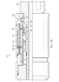
- FIG. 2A illustrates the downhole tool 100 in an open/unlocked configuration, in accordance with examples of the present disclosure.
- a top adapter 200 may be used to integrate the downhole tool 100 into a work string.
- the downhole tool 100 also includes an outer sleeve 202 that is disposed around an inner sleeve 204.
- the outer sleeve 202 is configured to move in axial directions along a longitudinal axis L of the downhole tool 100, relative to the inner sleeve 204.
- a sealing cap 206 pressure cap
- the sealing cap 206 may include a configurable pressure relief valve 208.
- the relief valve 208 (e.g., a check valve) may be configured to pass fluid at a desired/threshold pressure.
- a debris screen 210 may be positioned between the outer sleeve 202 and the inner sleeve 204.
- the debris screen 210 filters wellbore fluid (e.g., mud, drilling fluid) as it passes through the debris screen 210 via a port 212 positioned in the inner sleeve 204.
- wellbore fluid e.g., mud, drilling fluid
- a portion of the fluid travels through the port 212 and through the debris screen 210.
- the fluid may then move through a passage 213 and through the relief valve 208 (e.g., check valve) and into a chamber 214 contained in the outer sleeve 202.
- the chamber 214 may include a spring 216 (e.g., a first return spring) to assist with movement of the outer sleeve 202.
- a spring 216 e.g., a first return spring
- the volume of the chamber 214 may increase as the outer sleeve 202 is moved forward, and the volume of the chamber 214 may decrease as the outer sleeve 202 is moved backward.
- a distal end 218 of the outer sleeve 202 may include a passage 220 (e.g., lateral opening) that leads into a pocket 221.
- a profile 222 of the distal end 218 of the outer sleeve 202 may include a slant or ramp (e.g., facing inward) to guide a ball 226 inward/downward into a groove 227 of the inner sleeve 204.
- the groove 227 is adjacent to the passage 220.
- the ball 226 is positioned/secured against a member such as a spacer 230 and the outer sleeve 202 while in the passage 220 of the inner sleeve 204.
- the spacer 230 is configured to prevent pre-locking/undesired locking of the outer sleeve 202.
- the ball 226 is forced inward to move the spacer 230 inward (closer to a center of the downhole tool 100, see arrow 233) into the pocket 221, thereby allowing closure of the passage 220 and positioning of the ball 226 in the groove 227.
- the pocket 221 includes a spring 234 (e.g., a second return spring) to assist with moving/returning the outer sleeve 202 backward to its initial position.
- the pocket 221 includes a portion including a profile 236 (e.g., a ramp) to guide movement of the spacer 230 during compression and expansion of the spring 234. In the unlocked position, as shown, the spring 234 is expanded.
- the ball 226 In the open/unlocked position, the ball 226 receives an axial load from the outer sleeve 202 and is prevented from moving down into the groove 227 until the ball is moved inward. In the unlocked position, the ball 226 is positioned in the passage 220 between the outer sleeve 202, the inner sleeve 204, and the spacer 230 as shown on FIG. 2A .
- the outer sleeve 202 is moved forward (e.g., exerting a downward force on the tool string that includes the downhole tool 100) to move fluid (directional arrow 240) through the relief valve 208 into the chamber 214, causing expansion of the spring 216.
- the ball 226 moves into the groove 227 of the inner sleeve 204 as the outer sleeve 202 moves forward and forces the ball 226 inward (arrow 233) due to the profile 222.
- the valve 208 is configured to open at a desired threshold fluid pressure.
- the inward moving ball 226 forces the spacer 230 into the pocket 221 along the profile 236 and compresses the spring 234, thereby closing/locking the downhole tool 100.
- the spring 216 and the spring 234 are compressed in the locked position.
- the outer sleeve 202 is moved backward to the position shown on FIG. 2A .
- fluid exits (arrow 242) the chamber 214 via the valve 208.
- the valve 208 is configurable and passes the fluid at a configured/desired pressure (threshold pressure).
- the spring 216 compresses to move the outer sleeve 202 backward and the spring 234 expands to move the spacer 230 back along the profile 236 to move the ball 226 back into the passage 220 to unlock the tool.
- FIG. 3 illustrates an operative sequence for locking and unlocking the tool, in accordance with examples of the present disclosure.
- a downhole tool is locked by moving an outer sleeve of the downhole tool forward relative to an inner sleeve of the tool.
- the tool further includes a relief valve positioned in the outer sleeve.
- the relief valve is in fluid communication with a chamber that includes a first return spring configured to move the outer sleeve backward.
- fluid is passed through the relief valve into the chamber and the first return spring is expanded.
- a ball is moved with the outer sleeve from an initial position into a groove of the inner sleeve and a spacer is moved into a pocket of the inner sleeve and a second return spring that is disposed in the pocket is compressed.
- the second return spring is configured to move the spacer to and from the ball.
- the spacer is configured to move the ball back to the initial position. Locking steps 300, 302, and 304 may occur simultaneously.
- the downhole tool is unlocked by moving the outer sleeve backward relative to the inner sleeve and passing fluid from the chamber via the relief valve that is configured to pass fluid based on a threshold pressure.
- the first return spring is compressed, and the second return spring is expanded, and the ball is moved with the spacer, from the groove to the initial position. Unlocking steps 306 and 308 may occur simultaneously.
- systems and methods of the present disclosure use a downhole tool that utilizes pressure relief valves to configure the unlocking pressure.
- the systems and methods may include any of the various features disclosed herein, including one or more of the following statements.
- a downhole tool comprising: an inner sleeve; an outer sleeve including: a chamber and a pressure relief valve in communication with the chamber, wherein a first return spring is disposed in the chamber, wherein the outer sleeve is movable in forward and backward directions relative to the inner sleeve; a ball disposed between the outer sleeve and the inner sleeve; a spacer adjacent to the ball; a groove adjacent to the spacer, the groove configured to receive the ball upon movement of the outer sleeve in the forward direction; and a pocket configured to receive the spacer upon movement of the outer sleeve in the forward direction, the pocket including a second return spring, the spacer configured to travel to the ball from the pocket and from the ball to the pocket, wherein the pressure relief valve is configured to pass fluid based on a threshold pressure to unlock and move the outer sleeve in the backward direction.
- Statement 2 The downhole tool of the statement 1, wherein the pocket includes a profile configured to guide the spacer upon movement of the outer sleeve.
- Statement 3 The downhole tool of the statement 1 or the statement 2, wherein the profile includes a ramp.
- Statement 4 The downhole tool of any one of the statements 1-3, wherein the first return spring is expanded, and the outer sleeve is in a forward position.
- Statement 5 The downhole tool of any one of the statements 1-4, wherein the second return spring is compressed, and the outer sleeve is in the forward position.
- Statement 6 The downhole tool of any one of the statements 1-5, further comprising a filter configured to filter fluid passing into the chamber.
- Statement 7 The downhole tool of any one of the statements 1-6, wherein the outer sleeve includes a profile to move the ball inward into the groove.
- Statement 8 The downhole tool of any one of the statements 1-7, wherein the profile includes a ramp.
- Statement 9 The downhole tool of any one of the statements 1-8, wherein the fluid includes a drilling fluid.
- Statement 10 The downhole tool of any one of the statements 1-9, wherein the first return spring is compressed, and the outer sleeve is not in the forward position.
- Statement 11 The downhole tool of any one of the statements 1-10, wherein the second return spring is expanded, and the outer sleeve is not in the forward position.
- a method comprising: unlocking a downhole tool by moving an outer sleeve backward relative to an inner sleeve and passing fluid from a chamber via a pressure relief valve that is configured to pass fluid based on a threshold pressure, the downhole tool including: an inner sleeve; the outer sleeve including: the chamber and the pressure relief valve, wherein a first return spring is disposed in the chamber, wherein the outer sleeve is movable in forward and backward directions relative to the inner sleeve; a ball disposed between the outer sleeve and the inner sleeve; a spacer adjacent to the ball; a groove adjacent to the spacer, the groove configured to receive the ball upon movement of the outer sleeve in the forward direction; and a pocket configured to receive the spacer upon movement of the outer sleeve in the forward direction, the pocket including a second return spring, the spacer configured to travel to the ball from the pocket, and from the ball to the pocket.
- Statement 14 The method of any one of the statements 12 or 13, further comprising locking the downhole tool by moving the outer sleeve of the downhole tool forward relative to the inner sleeve of the tool.
- Statement 18 The method of any one of the statements 12-17, wherein the pocket includes a profile configured to guide the spacer upon movement of the outer sleeve.
- Statement 19 The method of any one of the statements 12-18, wherein the profile includes a ramp.
- Statement 20 The method of any one of the statements 12-19, wherein the outer sleeve includes a profile to move the ball inward into the groove.
- ranges from any lower limit may be combined with any upper limit to recite a range not explicitly recited, as well as ranges from any lower limit may be combined with any other lower limit to recite a range not explicitly recited, in the same way, ranges from any upper limit may be combined with any other upper limit to recite a range not explicitly recited.
- any numerical range with a lower limit and an upper limit is disclosed, any number and any included range falling within the range are specifically disclosed.
- every range of values (of the form, "from about a to about b,” or, equivalently, “from approximately a to b,” or, equivalently, “from approximately a-b") disclosed herein is to be understood to set forth every number and range encompassed within the broader range of values even if not explicitly recited.
- every point or individual value may serve as its own lower or upper limit combined with any other point or individual value or any other lower or upper limit, to recite a range not explicitly recited.
Landscapes
- Life Sciences & Earth Sciences (AREA)
- Engineering & Computer Science (AREA)
- Geology (AREA)
- Mining & Mineral Resources (AREA)
- Physics & Mathematics (AREA)
- Environmental & Geological Engineering (AREA)
- Fluid Mechanics (AREA)
- General Life Sciences & Earth Sciences (AREA)
- Geochemistry & Mineralogy (AREA)
- Safety Valves (AREA)
- Quick-Acting Or Multi-Walled Pipe Joints (AREA)
- Automatic Tool Replacement In Machine Tools (AREA)
Abstract
Description
- During some oilfield retrieval operations, a mechanism that locks a retrieving tool to a bridge plug may become stuck in the open position. Current parts can decentralize causing the locking mechanism to become bound inside its dynamic bore even with a return spring to assist closure. Current systems may also include a complex geometry where engaging components interact, thereby increasing production costs.
- These drawings illustrate certain aspects of some examples of the present disclosure and should not be used to limit or define the disclosure.
-
FIG. 1 illustrates an operating environment for a retrieval tool, in accordance with examples of the present disclosure; -
FIG. 2A illustrates the retrieval tool in an open/unlocked configuration, in accordance with examples of the present disclosure; -
FIG. 2B illustrates the retrieval tool in a closed/locked configuration, in accordance with examples of the present disclosure; and -
FIG. 3 illustrates an operative sequence for the retrieval tool, in accordance with examples of the present disclosure. - The present disclosure relates to a downhole tool that utilizes pressure relief valves to configure the unlocking pressure. With all components being part of the same sub assembly, there is not a potential for decentralization. This should prevent the locking feature from becoming stuck open. Components are designed such that basic machining processes (e.g., lathe, mill) may be used to create the components, and not require electrical discharge machining (EDM), for example. The systems as described herein may be configured to unlock at multiple pressures allowing tandem bridge plugs to be set in a single down hole trip. The system utilizes pressure relief valves to configure the unlocking pressure for the retrieving tool. The configurable disconnecting pressures may be used for setting tandem bridge plugs.
- The downhole tool includes an outer sleeve, an inner sleeve, a sealing cap and a top adapter. In an open/unlocked position, ball(s) designed to receive an axial load are prevented from moving down into pocket(s). For example, once the retrieving tool engages the bridge plug, a spacer (e.g., a rigid member) prevents the ball from moving into a pocket by moving outward from the pocket. This allows the ball to move into a groove on a piston housing and simultaneously allows the outer sleeve to close.
-
FIG. 1 illustrates a well system 110 (operating environment) for a downhole tool 100 (e.g., a retrieval tool), in accordance with examples of the present disclosure. In some examples, thedownhole tool 100 may be used to retrieve a plug (e.g., tandem bridge plug) from a wellbore. Aderrick 112 with arig floor 114 is positioned on the earth'ssurface 105. Awellbore 120 is positioned below thederrick 112 and therig floor 114 and extends into asubterranean formation 115. Thewellbore 120 may be lined withcasing 125 that is cemented in place withcement 127. AlthoughFIG. 1 depicts thewellbore 120 having acasing 125 being cemented into place withcement 127, thewellbore 120 may includeopen hole portion 128. Moreover, thewellbore 120 may be an open-hole wellbore. Thewell system 110 may equally be employed in vertical and/or deviated wellbores. - A
tool string 118 extends from thederrick 112 and therig floor 114 downwardly into thewellbore 120. Thetool string 118 may be any mechanical connection to the surface, such as, for example, jointed pipe, wireline, slickline, or coiled tubing. As depicted, thetool string 118 suspends thedownhole tool 100 for placement into thewellbore 120 at a desired location to perform a specific downhole operation. -
FIG. 2A illustrates thedownhole tool 100 in an open/unlocked configuration, in accordance with examples of the present disclosure. Atop adapter 200 may be used to integrate thedownhole tool 100 into a work string. Thedownhole tool 100 also includes anouter sleeve 202 that is disposed around aninner sleeve 204. Theouter sleeve 202 is configured to move in axial directions along a longitudinal axis L of thedownhole tool 100, relative to theinner sleeve 204. A sealing cap 206 (pressure cap) may be included in theouter sleeve 202. The sealingcap 206 may include a configurablepressure relief valve 208. The relief valve 208 (e.g., a check valve) may be configured to pass fluid at a desired/threshold pressure. - A
debris screen 210 may be positioned between theouter sleeve 202 and theinner sleeve 204. Thedebris screen 210 filters wellbore fluid (e.g., mud, drilling fluid) as it passes through thedebris screen 210 via aport 212 positioned in theinner sleeve 204. As theouter sleeve 202 is pushed forward, wellbore fluid passes through the tool string and thedownhole tool 100. A portion of the fluid travels through theport 212 and through thedebris screen 210. The fluid may then move through apassage 213 and through the relief valve 208 (e.g., check valve) and into achamber 214 contained in theouter sleeve 202. Thechamber 214 may include a spring 216 (e.g., a first return spring) to assist with movement of theouter sleeve 202. In the unlocked position, as shown, thespring 216 is compressed. The volume of thechamber 214 may increase as theouter sleeve 202 is moved forward, and the volume of thechamber 214 may decrease as theouter sleeve 202 is moved backward. - A
distal end 218 of theouter sleeve 202 may include a passage 220 (e.g., lateral opening) that leads into apocket 221. Aprofile 222 of thedistal end 218 of theouter sleeve 202 may include a slant or ramp (e.g., facing inward) to guide aball 226 inward/downward into agroove 227 of theinner sleeve 204. Thegroove 227 is adjacent to thepassage 220. Theball 226 is positioned/secured against a member such as aspacer 230 and theouter sleeve 202 while in thepassage 220 of theinner sleeve 204. Thespacer 230 is configured to prevent pre-locking/undesired locking of theouter sleeve 202. As theouter sleeve 202 is moved forward (arrow 231), theball 226 is forced inward to move thespacer 230 inward (closer to a center of thedownhole tool 100, see arrow 233) into thepocket 221, thereby allowing closure of thepassage 220 and positioning of theball 226 in thegroove 227. - The
pocket 221 includes a spring 234 (e.g., a second return spring) to assist with moving/returning theouter sleeve 202 backward to its initial position. Thepocket 221 includes a portion including a profile 236 (e.g., a ramp) to guide movement of thespacer 230 during compression and expansion of thespring 234. In the unlocked position, as shown, thespring 234 is expanded. - In the open/unlocked position, the
ball 226 receives an axial load from theouter sleeve 202 and is prevented from moving down into thegroove 227 until the ball is moved inward. In the unlocked position, theball 226 is positioned in thepassage 220 between theouter sleeve 202, theinner sleeve 204, and thespacer 230 as shown onFIG. 2A . - To move from the open position on
FIG. 2A to a closed position ofFIG. 2B , theouter sleeve 202 is moved forward (e.g., exerting a downward force on the tool string that includes the downhole tool 100) to move fluid (directional arrow 240) through therelief valve 208 into thechamber 214, causing expansion of thespring 216. Theball 226 moves into thegroove 227 of theinner sleeve 204 as theouter sleeve 202 moves forward and forces theball 226 inward (arrow 233) due to theprofile 222. Thevalve 208 is configured to open at a desired threshold fluid pressure. With additional reference toFIG. 2B , the inward movingball 226 forces thespacer 230 into thepocket 221 along theprofile 236 and compresses thespring 234, thereby closing/locking thedownhole tool 100. Thespring 216 and thespring 234 are compressed in the locked position. - To unlock the
downhole tool 100, theouter sleeve 202 is moved backward to the position shown onFIG. 2A . As theouter sleeve 202 is pulled back, fluid exits (arrow 242) thechamber 214 via thevalve 208. Thevalve 208 is configurable and passes the fluid at a configured/desired pressure (threshold pressure). Thespring 216 compresses to move theouter sleeve 202 backward and thespring 234 expands to move thespacer 230 back along theprofile 236 to move theball 226 back into thepassage 220 to unlock the tool. -
FIG. 3 illustrates an operative sequence for locking and unlocking the tool, in accordance with examples of the present disclosure. Atstep 300, a downhole tool is locked by moving an outer sleeve of the downhole tool forward relative to an inner sleeve of the tool. The tool further includes a relief valve positioned in the outer sleeve. The relief valve is in fluid communication with a chamber that includes a first return spring configured to move the outer sleeve backward. Atstep 302, fluid is passed through the relief valve into the chamber and the first return spring is expanded. - At
step 304, a ball is moved with the outer sleeve from an initial position into a groove of the inner sleeve and a spacer is moved into a pocket of the inner sleeve and a second return spring that is disposed in the pocket is compressed. The second return spring is configured to move the spacer to and from the ball. The spacer is configured to move the ball back to the initial position. Lockingsteps - At
step 306, the downhole tool is unlocked by moving the outer sleeve backward relative to the inner sleeve and passing fluid from the chamber via the relief valve that is configured to pass fluid based on a threshold pressure. Atstep 308, the first return spring is compressed, and the second return spring is expanded, and the ball is moved with the spacer, from the groove to the initial position. Unlockingsteps - Accordingly, the systems and methods of the present disclosure use a downhole tool that utilizes pressure relief valves to configure the unlocking pressure. The systems and methods may include any of the various features disclosed herein, including one or more of the following statements.
- Statement 1. A downhole tool comprising: an inner sleeve; an outer sleeve including: a chamber and a pressure relief valve in communication with the chamber, wherein a first return spring is disposed in the chamber, wherein the outer sleeve is movable in forward and backward directions relative to the inner sleeve; a ball disposed between the outer sleeve and the inner sleeve; a spacer adjacent to the ball; a groove adjacent to the spacer, the groove configured to receive the ball upon movement of the outer sleeve in the forward direction; and a pocket configured to receive the spacer upon movement of the outer sleeve in the forward direction, the pocket including a second return spring, the spacer configured to travel to the ball from the pocket and from the ball to the pocket, wherein the pressure relief valve is configured to pass fluid based on a threshold pressure to unlock and move the outer sleeve in the backward direction.
- Statement 2. The downhole tool of the statement 1, wherein the pocket includes a profile configured to guide the spacer upon movement of the outer sleeve.
- Statement 3. The downhole tool of the statement 1 or the statement 2, wherein the profile includes a ramp.
- Statement 4. The downhole tool of any one of the statements 1-3, wherein the first return spring is expanded, and the outer sleeve is in a forward position.
- Statement 5. The downhole tool of any one of the statements 1-4, wherein the second return spring is compressed, and the outer sleeve is in the forward position.
- Statement 6. The downhole tool of any one of the statements 1-5, further comprising a filter configured to filter fluid passing into the chamber.
- Statement 7. The downhole tool of any one of the statements 1-6, wherein the outer sleeve includes a profile to move the ball inward into the groove.
- Statement 8. The downhole tool of any one of the statements 1-7, wherein the profile includes a ramp.
- Statement 9. The downhole tool of any one of the statements 1-8, wherein the fluid includes a drilling fluid.
- Statement 10. The downhole tool of any one of the statements 1-9, wherein the first return spring is compressed, and the outer sleeve is not in the forward position.
- Statement 11. The downhole tool of any one of the statements 1-10, wherein the second return spring is expanded, and the outer sleeve is not in the forward position.
- Statement 12. A method comprising: unlocking a downhole tool by moving an outer sleeve backward relative to an inner sleeve and passing fluid from a chamber via a pressure relief valve that is configured to pass fluid based on a threshold pressure, the downhole tool including: an inner sleeve; the outer sleeve including: the chamber and the pressure relief valve, wherein a first return spring is disposed in the chamber, wherein the outer sleeve is movable in forward and backward directions relative to the inner sleeve; a ball disposed between the outer sleeve and the inner sleeve; a spacer adjacent to the ball; a groove adjacent to the spacer, the groove configured to receive the ball upon movement of the outer sleeve in the forward direction; and a pocket configured to receive the spacer upon movement of the outer sleeve in the forward direction, the pocket including a second return spring, the spacer configured to travel to the ball from the pocket, and from the ball to the pocket.
- Statement 13. The method of the statement 12, wherein the unlocking further comprises moving the ball from the groove of the inner sleeve and moving the spacer from the pocket of the inner sleeve and expanding the second return spring to move the spacer from the pocket to the ball.
- Statement 14. The method of any one of the statements 12 or 13, further comprising locking the downhole tool by moving the outer sleeve of the downhole tool forward relative to the inner sleeve of the tool.
- Statement 15. The method of any one of the statements 12-14, wherein the locking further comprises passing fluid through the relief valve into the chamber and expanding the first return spring.
- Statement 16. The method of any one of the statements 12-15, wherein the locking further comprises moving the ball with the outer sleeve into the groove of the inner sleeve and moving the spacer into the pocket and compressing the second return spring with the spacer.
- Statement 17. The method of any one of the statements 12-16, wherein the locking further comprises expanding the first return spring.
- Statement 18. The method of any one of the statements 12-17, wherein the pocket includes a profile configured to guide the spacer upon movement of the outer sleeve.
- Statement 19. The method of any one of the statements 12-18, wherein the profile includes a ramp.
- Statement 20. The method of any one of the statements 12-19, wherein the outer sleeve includes a profile to move the ball inward into the groove.
- Although the present disclosure and its advantages have been described in detail, it should be understood that various changes, substitutions, and alterations may be made herein without departing from the spirit and scope of the disclosure as defined by the appended claims. The preceding description provides various examples of the systems and methods of use disclosed herein which may contain different method steps and alternative combinations of components. It should be understood that, although individual examples may be discussed herein, the present disclosure covers all combinations of the disclosed examples, including, without limitation, the different component combinations, method step combinations, and properties of the system. It should be understood that the compositions and methods are described in terms of "comprising," "containing," or "including" various components or steps, the compositions and methods can also "consist essentially of" or "consist of" the various components and steps. Moreover, the indefinite articles "a" or "an," as used in the claims, are defined herein to mean one or more than one of the elements that it introduces.
- For the sake of brevity, only certain ranges are explicitly disclosed herein. However, ranges from any lower limit may be combined with any upper limit to recite a range not explicitly recited, as well as ranges from any lower limit may be combined with any other lower limit to recite a range not explicitly recited, in the same way, ranges from any upper limit may be combined with any other upper limit to recite a range not explicitly recited. Additionally, whenever a numerical range with a lower limit and an upper limit is disclosed, any number and any included range falling within the range are specifically disclosed. In particular, every range of values (of the form, "from about a to about b," or, equivalently, "from approximately a to b," or, equivalently, "from approximately a-b") disclosed herein is to be understood to set forth every number and range encompassed within the broader range of values even if not explicitly recited. Thus, every point or individual value may serve as its own lower or upper limit combined with any other point or individual value or any other lower or upper limit, to recite a range not explicitly recited.
- Therefore, the present examples are well adapted to attain the ends and advantages mentioned as well as those that are inherent therein. The particular examples disclosed above are illustrative only and may be modified and practiced in different but equivalent manners apparent to those skilled in the art having the benefit of the teachings herein. Although individual examples are discussed, the disclosure covers all combinations of all of the examples. Furthermore, no limitations are intended to the details of construction or design herein shown, other than as described in the claims below. Also, the terms in the claims have their plain, ordinary meaning unless otherwise explicitly and clearly defined by the patentee. It is therefore evident that the particular illustrative examples disclosed above may be altered or modified and all such variations are considered within the scope and spirit of those examples. If there is any conflict in the usages of a word or term in this specification and one or more patent(s) or other documents that may be incorporated herein by reference, the definitions that are consistent with this specification should be adopted.
Claims (15)
- A downhole tool comprising:an inner sleeve;an outer sleeve including:
a chamber and a pressure relief valve in communication with the chamber, wherein a first return spring is disposed in the chamber, wherein the outer sleeve is movable in forward and backward directions relative to the inner sleeve;a ball disposed between the outer sleeve and the inner sleeve;a spacer adjacent to the ball;a groove adjacent to the spacer, the groove configured to receive the ball upon movement of the outer sleeve in the forward direction; anda pocket configured to receive the spacer upon movement of the outer sleeve in the forward direction, the pocket including a second return spring, the spacer configured to travel to the ball from the pocket and from the ball to the pocket, wherein the pressure relief valve is configured to pass fluid based on a threshold pressure to unlock and move the outer sleeve in the backward direction. - The downhole tool of claim 1, wherein the pocket includes a profile configured to guide the spacer upon movement of the outer sleeve and optionally, wherein the profile includes a ramp.
- The downhole tool of claim 1, wherein the first return spring is expanded, and the outer sleeve is in a forward position and optionally, wherein the second return spring is compressed, and the outer sleeve is in the forward position.
- The downhole tool of claim 1, further comprising a filter configured to filter fluid passing into the chamber and optionally, wherein the outer sleeve includes a profile to move the ball inward into the groove.
- The downhole tool of claim 4, wherein the profile includes a ramp and optionally, wherein the fluid includes a drilling fluid.
- The downhole tool of claim 1, wherein the first return spring is compressed, and the outer sleeve is not in the forward position.
- The downhole tool of claim 1, wherein the second return spring is expanded, and the outer sleeve is not in the forward position.
- A method comprising:
unlocking a downhole tool by moving an outer sleeve backward relative to an inner sleeve and passing fluid from a chamber via a pressure relief valve that is configured to pass fluid based on a threshold pressure, the downhole tool including:an inner sleeve;the outer sleeve including:
the chamber and the pressure relief valve, wherein a first return spring is disposed in the chamber, wherein the outer sleeve is movable in forward and backward directions relative to the inner sleeve;a ball disposed between the outer sleeve and the inner sleeve;a spacer adjacent to the ball;a groove adjacent to the spacer, the groove configured to receive the ball upon movement of the outer sleeve in the forward direction; anda pocket configured to receive the spacer upon movement of the outer sleeve in the forward direction, the pocket including a second return spring, the spacer configured to travel to the ball from the pocket, and from the ball to the pocket. - The method of claim 8, wherein the unlocking further comprises moving the ball from the groove of the inner sleeve and moving the spacer from the pocket of the inner sleeve and expanding the second return spring to move the spacer from the pocket to the ball.
- The method of claim 8, further comprising locking the downhole tool by moving the outer sleeve of the downhole tool forward relative to the inner sleeve of the tool.
- The method of claim 10, wherein the locking further comprises passing fluid through the relief valve into the chamber and expanding the first return spring.
- The method of claim 10, wherein the locking further comprises moving the ball with the outer sleeve into the groove of the inner sleeve and moving the spacer into the pocket and compressing the second return spring with the spacer.
- The method of claim 12, wherein the locking further comprises expanding the first return spring.
- The method tool of claim 8, wherein the pocket includes a profile configured to guide the spacer upon movement of the outer sleeve.
- The method of claim 14, wherein the profile includes a ramp and optionally, wherein the outer sleeve includes a profile to move the ball inward into the groove.
Applications Claiming Priority (1)
| Application Number | Priority Date | Filing Date | Title |
|---|---|---|---|
| US18/310,392 US12146388B1 (en) | 2023-05-01 | 2023-05-01 | Push on and pull off configurable retrieving system for intercept retrievable bridge plug |
Publications (1)
| Publication Number | Publication Date |
|---|---|
| EP4459094A1 true EP4459094A1 (en) | 2024-11-06 |
Family
ID=89771609
Family Applications (1)
| Application Number | Title | Priority Date | Filing Date |
|---|---|---|---|
| EP24154806.4A Pending EP4459094A1 (en) | 2023-05-01 | 2024-01-30 | Push on and pull off configurable retrieving |
Country Status (4)
| Country | Link |
|---|---|
| US (1) | US12146388B1 (en) |
| EP (1) | EP4459094A1 (en) |
| AU (1) | AU2023446609B2 (en) |
| WO (1) | WO2024228714A1 (en) |
Families Citing this family (1)
| Publication number | Priority date | Publication date | Assignee | Title |
|---|---|---|---|---|
| CN121675467B (en) * | 2026-02-06 | 2026-04-14 | 中冶华天工程技术有限公司 | A flexible anti-buoyancy prefabricated structure and its flexible anti-buoyancy method |
Citations (3)
| Publication number | Priority date | Publication date | Assignee | Title |
|---|---|---|---|---|
| US4869325A (en) * | 1986-06-23 | 1989-09-26 | Baker Hughes Incorporated | Method and apparatus for setting, unsetting, and retrieving a packer or bridge plug from a subterranean well |
| WO2016113577A2 (en) * | 2015-01-16 | 2016-07-21 | Xtreme Well Technology Limited | Downhole actuator device, apparatus, setting tool and methods of use |
| WO2021113758A1 (en) * | 2019-12-06 | 2021-06-10 | Hunting Titan, Inc. | Impact resistant material in setting tool |
Family Cites Families (12)
| Publication number | Priority date | Publication date | Assignee | Title |
|---|---|---|---|---|
| US4007783A (en) * | 1974-12-18 | 1977-02-15 | Otis Engineering Corporation | Well plug with anchor means |
| US7673693B2 (en) | 2007-06-13 | 2010-03-09 | Halliburton Energy Services, Inc. | Hydraulic coiled tubing retrievable bridge plug |
| WO2014185910A1 (en) | 2013-05-16 | 2014-11-20 | Halliburton Energy Services, Inc. | Systems and methods for releasing a tool string |
| GB2560837B (en) | 2015-11-19 | 2021-08-04 | Impact Selector Int Llc | Downhole apparatus |
| US10590731B2 (en) | 2017-09-28 | 2020-03-17 | Halliburton Energy Services, Inc. | Retrieval of a sealing assembly |
| AU2018344162B2 (en) * | 2017-10-03 | 2023-11-23 | Reflex Instruments Asia Pacific Pty Ltd | Downhole device delivery and associated drive transfer system and method of delivering a device down a hole |
| USD1041608S1 (en) | 2020-03-20 | 2024-09-10 | DynaEnergetics Europe GmbH | Outer connector |
| CN113356792B (en) * | 2021-05-28 | 2024-11-12 | 阜新市石油工具厂 | Repeated Sealing Bridge Plug |
| US12467328B2 (en) | 2021-06-01 | 2025-11-11 | Gr Energy Services Management, Lp | Downhole release tool with integrated igniter and method of using same |
| CN113356786B (en) * | 2021-07-16 | 2021-11-12 | 大庆市德油力机械加工有限公司 | Bidirectional slip packer using fishing spear to unseal and force releasing |
| CN116006125B (en) | 2021-10-21 | 2025-04-08 | 中国石油天然气集团有限公司 | Closable differential pressure sliding sleeve |
| CN115263249B (en) * | 2022-07-08 | 2024-02-13 | 中煤科工集团西安研究院有限公司 | Controllable release type seeker, bare hole lower screen pipe device and method |
-
2023
- 2023-05-01 US US18/310,392 patent/US12146388B1/en active Active
- 2023-05-23 WO PCT/US2023/023196 patent/WO2024228714A1/en not_active Ceased
- 2023-05-23 AU AU2023446609A patent/AU2023446609B2/en active Active
-
2024
- 2024-01-30 EP EP24154806.4A patent/EP4459094A1/en active Pending
Patent Citations (3)
| Publication number | Priority date | Publication date | Assignee | Title |
|---|---|---|---|---|
| US4869325A (en) * | 1986-06-23 | 1989-09-26 | Baker Hughes Incorporated | Method and apparatus for setting, unsetting, and retrieving a packer or bridge plug from a subterranean well |
| WO2016113577A2 (en) * | 2015-01-16 | 2016-07-21 | Xtreme Well Technology Limited | Downhole actuator device, apparatus, setting tool and methods of use |
| WO2021113758A1 (en) * | 2019-12-06 | 2021-06-10 | Hunting Titan, Inc. | Impact resistant material in setting tool |
Also Published As
| Publication number | Publication date |
|---|---|
| AU2023446609A1 (en) | 2025-09-25 |
| US12146388B1 (en) | 2024-11-19 |
| WO2024228714A1 (en) | 2024-11-07 |
| US20240368967A1 (en) | 2024-11-07 |
| AU2023446609B2 (en) | 2026-06-04 |
Similar Documents
| Publication | Publication Date | Title |
|---|---|---|
| EP3380699B1 (en) | Stage cementing tool and method | |
| US7108071B2 (en) | Automatic tubing filler | |
| US5641023A (en) | Shifting tool for a subterranean completion structure | |
| AU2009212867B2 (en) | Downhole window finder system | |
| US9260939B2 (en) | Systems and methods for reclosing a sliding side door | |
| CA2998108C (en) | Downhole valve assembly and method of using same | |
| EP1101012A1 (en) | Mechanism for dropping a plurality of balls into tubulars used in drilling, completion and workover of oil, gas and geothermal wells, and method of using same | |
| CA2850974C (en) | Downhole tool with pumpable section | |
| US9850742B2 (en) | Reclosable sleeve assembly and methods for isolating hydrocarbon production | |
| US12146388B1 (en) | Push on and pull off configurable retrieving system for intercept retrievable bridge plug | |
| US7373979B2 (en) | Workstring and a method for gravel packing | |
| US9470064B2 (en) | Safety valve, downhole system having safety valve, and method | |
| US12371961B1 (en) | Intensifying setting tool for packer | |
| EP1635035A1 (en) | Hydraulically operated protection for downhole devices | |
| US20210324709A1 (en) | Setting tool and method | |
| US12631089B2 (en) | Resettable configurable intercept sub surface control valve | |
| EP2719856A2 (en) | Seal assembly for subsurface safety valve | |
| WO2026029838A1 (en) | Intensifying setting tool for packer |
Legal Events
| Date | Code | Title | Description |
|---|---|---|---|
| PUAI | Public reference made under article 153(3) epc to a published international application that has entered the european phase |
Free format text: ORIGINAL CODE: 0009012 |
|
| STAA | Information on the status of an ep patent application or granted ep patent |
Free format text: STATUS: THE APPLICATION HAS BEEN PUBLISHED |
|
| AK | Designated contracting states |
Kind code of ref document: A1 Designated state(s): AL AT BE BG CH CY CZ DE DK EE ES FI FR GB GR HR HU IE IS IT LI LT LU LV MC ME MK MT NL NO PL PT RO RS SE SI SK SM TR |
|
| STAA | Information on the status of an ep patent application or granted ep patent |
Free format text: STATUS: REQUEST FOR EXAMINATION WAS MADE |
|
| 17P | Request for examination filed |
Effective date: 20241220 |
|
| STAA | Information on the status of an ep patent application or granted ep patent |
Free format text: STATUS: EXAMINATION IS IN PROGRESS |
|
| 17Q | First examination report despatched |
Effective date: 20250422 |
|
| GRAP | Despatch of communication of intention to grant a patent |
Free format text: ORIGINAL CODE: EPIDOSNIGR1 |
|
| STAA | Information on the status of an ep patent application or granted ep patent |
Free format text: STATUS: GRANT OF PATENT IS INTENDED |
|
| INTG | Intention to grant announced |
Effective date: 20260324 |
|
| RAP3 | Party data changed (applicant data changed or rights of an application transferred) |
Owner name: HALLIBURTON ENERGY SERVICES, INC. |
|
| GRAS | Grant fee paid |
Free format text: ORIGINAL CODE: EPIDOSNIGR3 |
|
| GRAA | (expected) grant |
Free format text: ORIGINAL CODE: 0009210 |
|
| STAA | Information on the status of an ep patent application or granted ep patent |
Free format text: STATUS: THE PATENT HAS BEEN GRANTED |