EP4459054A1 - Improved hinge for a work vehicle - Google Patents
Improved hinge for a work vehicle Download PDFInfo
- Publication number
- EP4459054A1 EP4459054A1 EP24172057.2A EP24172057A EP4459054A1 EP 4459054 A1 EP4459054 A1 EP 4459054A1 EP 24172057 A EP24172057 A EP 24172057A EP 4459054 A1 EP4459054 A1 EP 4459054A1
- Authority
- EP
- European Patent Office
- Prior art keywords
- hinge
- wear
- bushing
- signal
- sensor
- Prior art date
- Legal status (The legal status is an assumption and is not a legal conclusion. Google has not performed a legal analysis and makes no representation as to the accuracy of the status listed.)
- Pending
Links
Images

Classifications
-
- E—FIXED CONSTRUCTIONS
- E02—HYDRAULIC ENGINEERING; FOUNDATIONS; SOIL SHIFTING
- E02F—DREDGING; SOIL-SHIFTING
- E02F9/00—Component parts of dredgers or soil-shifting machines, not restricted to one of the kinds covered by groups E02F3/00 - E02F7/00
- E02F9/26—Indicating devices
- E02F9/267—Diagnosing or detecting failure of vehicles
-
- E—FIXED CONSTRUCTIONS
- E02—HYDRAULIC ENGINEERING; FOUNDATIONS; SOIL SHIFTING
- E02F—DREDGING; SOIL-SHIFTING
- E02F9/00—Component parts of dredgers or soil-shifting machines, not restricted to one of the kinds covered by groups E02F3/00 - E02F7/00
- E02F9/006—Pivot joint assemblies
-
- E—FIXED CONSTRUCTIONS
- E02—HYDRAULIC ENGINEERING; FOUNDATIONS; SOIL SHIFTING
- E02F—DREDGING; SOIL-SHIFTING
- E02F9/00—Component parts of dredgers or soil-shifting machines, not restricted to one of the kinds covered by groups E02F3/00 - E02F7/00
- E02F9/26—Indicating devices
- E02F9/264—Sensors and their calibration for indicating the position of the work tool
-
- F—MECHANICAL ENGINEERING; LIGHTING; HEATING; WEAPONS; BLASTING
- F16—ENGINEERING ELEMENTS AND UNITS; GENERAL MEASURES FOR PRODUCING AND MAINTAINING EFFECTIVE FUNCTIONING OF MACHINES OR INSTALLATIONS; THERMAL INSULATION IN GENERAL
- F16C—SHAFTS; FLEXIBLE SHAFTS; ELEMENTS OR CRANKSHAFT MECHANISMS; ROTARY BODIES OTHER THAN GEARING ELEMENTS; BEARINGS
- F16C17/00—Sliding-contact bearings for exclusively rotary movement
- F16C17/12—Sliding-contact bearings for exclusively rotary movement characterised by features not related to the direction of the load
- F16C17/24—Sliding-contact bearings for exclusively rotary movement characterised by features not related to the direction of the load with devices affected by abnormal or undesired positions, e.g. for preventing overheating, for safety
- F16C17/246—Sliding-contact bearings for exclusively rotary movement characterised by features not related to the direction of the load with devices affected by abnormal or undesired positions, e.g. for preventing overheating, for safety related to wear, e.g. sensors for measuring wear
Definitions
- the present invention concerns a hinge for a work vehicle, in particular a hinge for an implement of a work vehicle.
- the present invention finds its preferred, although not exclusive, application in a hinge of a heavy vehicle, such as an excavator or a loader. Reference will be made to this application by way of example below.
- a work vehicle such as an excavator or a loader, comprises a plurality of hinges, each of which allows relative rotation between two elements of the work vehicle.
- the work vehicle may comprise a frame and a front implement connected thereto, wherein the implement comprises a first arm hinged to the frame, a second arm hinged to the first arm, a third arm hinged to the second arm, and a bucket hinged to the third arm.
- the hinges are subject to wear.
- a hinge wears out there is a problem which does not only concern such hinge. Indeed, many components of the work vehicle are also damaged. This can also lead to safety issues, which increase over time if no action is taken. Fixing the problem caused by the hinge is often more costly than replacing the worn component.
- An aim of the present invention is to satisfy the above-mentioned need in a cost-effective and optimised manner.
- Figures 1 and 2 illustrate respective work vehicles 1 comprising respective implements 2.
- the vehicles 1 are heavy vehicles, respectively an excavator ( figure 1 ) and a loader ( figure 2 ).
- the vehicle 1 (i.e. each of the excavator and the loader) is of known type and comprises a front portion 3, a rear portion 4, and a cab 5 for a user of the vehicle 1.
- the implement 2 comprises a bucket 6, a plurality of arms 7 configured to connect the bucket 6 to the front portion 3 of the vehicle 1, and a plurality of cylinders 8 configured to move the arms 7 and thus the implement 2.
- the vehicle 1, in particular the implement 2, comprises a plurality of hinges 11 described in detail hereinafter.
- Each hinge 11 is configured to connect two elements of the vehicle 11 so as to allow relative rotation therebetween.
- Such two elements are e.g. the front portion 3 and the arm 7 hinged thereto, two consecutive arms 7, the arm 7 and the bucket 6 hinged thereto, the arm 7 and an end of the cylinder 8 hinged thereto.
- the hinge 11 (i.e. any of the aforementioned hinges 11) comprises ( figure 3 ) a pin 21 defining an axis A, a housing 22 configured to house the pin 21, and a bushing 23 radially interposed between the pin 21 and the housing 22.
- the pin 21 comprises a cylindrical element 31 of axis A
- the housing 22 defines a cylindrical seat 32 of axis A wherein the cylindrical element 31 is housed
- the bushing 23 comprises a tubular element 33 of axis A which is housed in the cylindrical seat 32.
- the tubular element 33 is located radially inside the cylindrical seat 32 and radially outside the cylindrical element 31.
- the pin 21 is rotatable with respect to the housing 22, in particular the cylindrical element 31 is rotatable with respect to the cylindrical seat 32.
- the hinge 11 is provided with sensor means 41 configured to detect wear of the bushing 23.
- the sensor means 41 are associated with the pin 21, the housing 22 or the bushing 23.
- the sensor means 41 detect wear of the bushing 23 by exploiting the interaction between the bushing 23 and the pin 21 and/or the bushing 23 and the housing 22.
- the sensor means 41 are integrated in the bushing 23.
- the bushing 23 comprises an inner radial surface 51 and an outer radial surface 52.
- the inner radial surface 51 is a cylindrical surface with an inner radius IR
- the outer radial surface 52 is a cylindrical surface with an outer radius OR, wherein the outer radius OR is greater than the inner radius IR.
- the sensor means 41 are interposed between the inner radial surface 51 and the outer radial surface 52.
- the sensor means 41 may be closer to the inner radial surface 51 (as in the illustrated embodiment) or the outer radial surface 52, or they may be equidistant therefrom.
- the sensor means 41 are arranged at a predetermined distance D with respect to the inner radial surface 51 of the bushing 23.
- the predetermined distance D is less than the difference between the outer radius OR of the bushing 23 and the inner radius IR of the bushing 23.
- the predetermined distance D is associated with a wear threshold of the bushing 23.
- the predetermined distance D is defined via experimental data, which are obtained from several experiments, performed using known hinges 11, wherein a wear threshold of the bushing 23 is reached and the corresponding distance D is recorded.
- the wear threshold is less than or equal to a maximum acceptable wear threshold of the bushing 23.
- the sensor means 41 are housed in a portion of the bushing 23.
- the sensor means 41 comprise a mechanical sensor and/or an electrical sensor 61.
- the mechanical sensor is configured to change its structure upon wear of the bushing 23.
- the mechanical sensor changes its shape due to wear of the bushing 23.
- the mechanical sensor is arranged at a predetermined depth with respect to the bushing 23 and comprises an insert, e.g. metallic or plastic and preferably of a bright colour, which protrudes axially outside the bushing 23. Since wear of the bushing 23 is reflected in a structural change of the mechanical sensor, and thus of the insert, the mechanical sensor allows wear of the bushing 23 to be visually detected.
- the electrical sensor 61 is configured to detect wear of the bushing 23 and produce a wear signal indicative thereof.
- the wear signal depends on the interaction between the bushing 23 and the pin 21 and/or the bushing 23 and the housing 22.
- the wear signal is a discrete signal.
- the electrical sensor 61 is configured to transmit the wear signal upon contact with the pin 21.
- the wear signal depends on the interaction between the bushing 23 and the pin 21, in particular on the contact therebetween.
- the electrical sensor 61 is switchable between a first configuration, wherein the electrical sensor 61 is not in contact with the pin 21, and a second configuration, wherein the electrical sensor 61 is in contact with the pin 21.
- the wear signal is indicative of the configuration of the electrical sensor 61.
- the wear signal provides information on whether the electrical sensor 61 is not in contact with the pin 21, i.e. it is in the first configuration, or is in contact with the pin 21, i.e. it is in the second configuration.
- the electrical sensor 61 acts as a switch which can be in one out of two configurations, i.e. the first configuration and the second configuration.
- the wear signal is indicative of which of the two configurations is the current one. Therefore, the wear signal is a binary signal.
- the electrical sensor 61 is configured to transmit the wear signal upon switching from the first configuration to the second configuration.
- the pin 21 and the electrical sensor 61 are electrically conductive, whereas the bushing 23 is not.
- the first configuration, wherein the electrical sensor 61 is not in contact with the pin 21, corresponds to an open circuit
- the second configuration, wherein the electrical sensor 61 is in contact with the pin 21, corresponds to a closed circuit.
- the electrical sensor 61 transmits the wear signal.
- the electrical sensor 61 transmits the wear signal via a wire 62 or wirelessly.
- the vehicle 1 ( figures 1 and 2 ) comprises an electronic control unit 71 configured to receive the wear signal from the electrical sensor 61 and to transmit a warning signal on the basis of the wear signal.
- an electronic control unit 71 configured to receive the wear signal from the electrical sensor 61 and to transmit a warning signal on the basis of the wear signal.
- the electrical sensor 61 is configured to transmit the wear signal to the electronic control unit 71, which in turn is configured to transmit the warning signal in response to the wear signal.
- the electronic control unit 71 is configured to transmit the warning signal to an electronic device 81 communicatively coupled to the electronic control unit 71.
- the warning signal transmitted by the electronic control unit 71 is received by the electronic device 81 which can be internal to, i.e part of, the vehicle 1 or external, i.e. not part of, the vehicle 1.
- the electronic device 81 is configured to provide visual and/or acoustic information relating to the warning signal so as to warn e.g. the user of the vehicle 1.
- the electronic device 81 is a smartphone or a tablet wirelessly coupled to the electronic control unit 71 and provided with an application which provides visual and acoustic notifications to the user of the smartphone or the tablet.
- the smartphone or the tablet is an example of electronic device 81 which is external to, i.e. not part of, the vehicle 1 and configured to provide visual and acoustic information relating to the warning signal.
- the vehicle 1 comprises a display device 82 communicatively coupled to the electronic control unit 71.
- the display device 82 is configured to receive the warning signal and to display visual information on the basis of the warning signal.
- the display device 82 is located inside the cab 5 and is coupled to the electronic control unit 71 via wires or wirelessly.
- the display device 82 is an example of electronic device 81 which is internal to, i.e. part of, the vehicle 1 and configured to provide visual information relating to the warning signal. The visual information provided by the display device 82 allows the user of the vehicle 1 to be warned.
- the work vehicle 1 comprises a plurality of electrical sensors 61 associated with the respective hinges 11, i.e. each hinge 61 comprises the respective electrical sensor 61.
- the electronic control unit 71 is configured to receive a plurality of wear signals from the respective electrical sensors 61, wherein each wear signal is associated with the respective hinge 11, and to transmit a plurality of warning signals to at least one electronic device 81, wherein each warning signal is associated with the respective wear signal.
- each electrical sensor 61 is configured to transmit the respective wear signal to the electronic control unit 71.
- Each wear signal is associated with the respective hinge 11, i.e. the hinge 11 comprising the respective electrical sensor 61 transmitting such wear signal, and is distinguishable from all the other wear signals, i.e. the wear signals transmitted by the other electrical sensors 61 and associated with the respective hinges 11.
- the electronic control unit 71 is configured to transmit the respective warning signal, i.e. the warning signal associated with the respective wear signal which in turn is associated with the respective hinge 11, to one or more electronic devices 81, e.g. the display device 82 and/or one or more smartphones or tablets.
- each warning signal is ultimately associated with the respective hinge 11.
- the present invention also relates to a method for warning of wear in the vehicle 1.
- the method comprises the steps of:
- warning signal allows e.g. the user of the vehicle 1 to be warned.
- each warning signal is associated with the respective wear signal which in turn is associated with the respective hinge 11, the user is warned of the specific hinge 11 which is subject to wear.
- the hinge 11 is subject to wear.
- the bushing 23 wears out and its radial dimension decreases over time. This is due to the interaction between the bushing 23 and the pin 21, in particular the sliding therebetween.
- the electrical sensor 61 gets in contact with the pin 21 and transmits the respective wear signal to the electronic control unit 71 which receives the wear signal and transmits the respective warning signal to the electronic device 81, e.g. the display device 82 which receives the warning signal and displays visual information on the basis of the warning signal. Therefore, the user of the vehicle 1 is warned of wear of the specific hinge 11 and can take immediate action.
- the sensor means 41 of the hinge 11 allow to intervene quickly and increase safety, thus avoiding damages to many components of the vehicle 1 and safety issues which would otherwise increase over time.
- the sensor means 41 allow to easily identify the worn hinge 11, whose worn bushing 23 can be replaced.
- the vehicle 1 comprising a plurality of hinges 11 and a plurality of electrical sensors 61, associated with the respective hinges 11, allows to directly identify the specific hinge 11 whose worn bushing 23 needs to be replaced.
- the shape of the components may be different from that described.
- the sensor means 41 may be configured to detect wear of the bushing 23 due to the interaction between the bushing 23 and the housing 22.
Landscapes
- Engineering & Computer Science (AREA)
- General Engineering & Computer Science (AREA)
- Mining & Mineral Resources (AREA)
- Civil Engineering (AREA)
- Structural Engineering (AREA)
- Mechanical Engineering (AREA)
- Pivots And Pivotal Connections (AREA)
Abstract
Description
- The present invention concerns a hinge for a work vehicle, in particular a hinge for an implement of a work vehicle.
- The present invention finds its preferred, although not exclusive, application in a hinge of a heavy vehicle, such as an excavator or a loader. Reference will be made to this application by way of example below.
- As is known, a work vehicle, such as an excavator or a loader, comprises a plurality of hinges, each of which allows relative rotation between two elements of the work vehicle.
- For example, the work vehicle may comprise a frame and a front implement connected thereto, wherein the implement comprises a first arm hinged to the frame, a second arm hinged to the first arm, a third arm hinged to the second arm, and a bucket hinged to the third arm.
- In use, the hinges are subject to wear. When a hinge wears out, there is a problem which does not only concern such hinge. Indeed, many components of the work vehicle are also damaged. This can also lead to safety issues, which increase over time if no action is taken. Fixing the problem caused by the hinge is often more costly than replacing the worn component.
- Therefore, the need is felt to improve known hinges, work vehicles and methods so as to intervene quickly and increase safety.
- An aim of the present invention is to satisfy the above-mentioned need in a cost-effective and optimised manner.
- The aforementioned aim is reached by a hinge for a work vehicle, a work vehicle and a method as claimed in the appended set of claims.
- For a better understanding of the present invention, a preferred embodiment is described in the following, by way of a non-limiting example, with reference to the attached drawings wherein:
-
figures 1 and 2 are side views of respective work vehicles comprising a plurality of hinges according to the invention; -
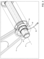
figure 3 is a perspective view of the hinge offigures 1 and 2 ; and -
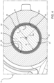
figure 4 is a front view of the hinge offigure 3 . -
Figures 1 and 2 illustrate respective work vehicles 1 comprisingrespective implements 2. In particular, the vehicles 1 are heavy vehicles, respectively an excavator (figure 1 ) and a loader (figure 2 ). - The vehicle 1 (i.e. each of the excavator and the loader) is of known type and comprises a
front portion 3, arear portion 4, and a cab 5 for a user of the vehicle 1. Theimplement 2 comprises abucket 6, a plurality ofarms 7 configured to connect thebucket 6 to thefront portion 3 of the vehicle 1, and a plurality ofcylinders 8 configured to move thearms 7 and thus theimplement 2. - The vehicle 1, in particular the
implement 2, comprises a plurality ofhinges 11 described in detail hereinafter. - Each
hinge 11 is configured to connect two elements of thevehicle 11 so as to allow relative rotation therebetween. - Such two elements are e.g. the
front portion 3 and thearm 7 hinged thereto, twoconsecutive arms 7, thearm 7 and thebucket 6 hinged thereto, thearm 7 and an end of thecylinder 8 hinged thereto. - The hinge 11 (i.e. any of the aforementioned hinges 11) comprises (
figure 3 ) apin 21 defining an axis A, ahousing 22 configured to house thepin 21, and abushing 23 radially interposed between thepin 21 and thehousing 22. - In particular (
figure 4 ), thepin 21 comprises acylindrical element 31 of axis A, thehousing 22 defines acylindrical seat 32 of axis A wherein thecylindrical element 31 is housed, and thebushing 23 comprises atubular element 33 of axis A which is housed in thecylindrical seat 32. Thetubular element 33 is located radially inside thecylindrical seat 32 and radially outside thecylindrical element 31. - Conveniently, the
pin 21 is rotatable with respect to thehousing 22, in particular thecylindrical element 31 is rotatable with respect to thecylindrical seat 32. - The
hinge 11 is provided with sensor means 41 configured to detect wear of thebushing 23. - In particular, the sensor means 41 are associated with the
pin 21, thehousing 22 or thebushing 23. - Conveniently, the sensor means 41 detect wear of the
bushing 23 by exploiting the interaction between thebushing 23 and thepin 21 and/or thebushing 23 and thehousing 22. - Preferably, the sensor means 41 are integrated in the
bushing 23. - According to the illustrated embodiment, the
bushing 23 comprises an innerradial surface 51 and an outerradial surface 52. Conveniently, the innerradial surface 51 is a cylindrical surface with an inner radius IR, and the outerradial surface 52 is a cylindrical surface with an outer radius OR, wherein the outer radius OR is greater than the inner radius IR. The sensor means 41 are interposed between the innerradial surface 51 and the outerradial surface 52. The sensor means 41 may be closer to the inner radial surface 51 (as in the illustrated embodiment) or the outerradial surface 52, or they may be equidistant therefrom. - Preferably, the sensor means 41 are arranged at a predetermined distance D with respect to the inner
radial surface 51 of thebushing 23. - Conveniently, the predetermined distance D is less than the difference between the outer radius OR of the
bushing 23 and the inner radius IR of thebushing 23. - In particular, the sensor means 41 have an annular structure, e.g. as a sleeve, of axis A with a minimum radius R and the predetermined distance D is the difference between such radius R and the inner radius IR of the
bushing 23, i.e. D = R - IR. - Conveniently, the predetermined distance D is associated with a wear threshold of the
bushing 23. - In particular, the predetermined distance D is defined via experimental data, which are obtained from several experiments, performed using
known hinges 11, wherein a wear threshold of thebushing 23 is reached and the corresponding distance D is recorded. Conveniently, the wear threshold is less than or equal to a maximum acceptable wear threshold of thebushing 23. - According to another embodiment (not illustrated), the sensor means 41 are housed in a portion of the
bushing 23. - In particular:
- the
bushing 23, in particular the innerradial surface 51, may define a cavity which faces thepin 21 and wherein the sensor means 41 are housed; and/or - the
bushing 23, in particular the outerradial surface 52, may define a cavity which faces thehousing 22 and wherein the sensor means 41 are housed. - Irrespective of the relative position between the sensor means 41 and the
bushing 23, the sensor means 41 comprise a mechanical sensor and/or anelectrical sensor 61. - Preferably, the mechanical sensor is configured to change its structure upon wear of the
bushing 23. - In particular, the mechanical sensor changes its shape due to wear of the
bushing 23. For example, the mechanical sensor is arranged at a predetermined depth with respect to thebushing 23 and comprises an insert, e.g. metallic or plastic and preferably of a bright colour, which protrudes axially outside thebushing 23. Since wear of thebushing 23 is reflected in a structural change of the mechanical sensor, and thus of the insert, the mechanical sensor allows wear of thebushing 23 to be visually detected. - The
electrical sensor 61 is configured to detect wear of thebushing 23 and produce a wear signal indicative thereof. - In particular, the wear signal depends on the interaction between the
bushing 23 and thepin 21 and/or thebushing 23 and thehousing 22. Conveniently, the wear signal is a discrete signal. - According to the illustrated embodiment, the
electrical sensor 61 is configured to transmit the wear signal upon contact with thepin 21. - In particular, the wear signal depends on the interaction between the
bushing 23 and thepin 21, in particular on the contact therebetween. - Preferably, the
electrical sensor 61 is switchable between a first configuration, wherein theelectrical sensor 61 is not in contact with thepin 21, and a second configuration, wherein theelectrical sensor 61 is in contact with thepin 21. The wear signal is indicative of the configuration of theelectrical sensor 61. - In particular, the wear signal provides information on whether the
electrical sensor 61 is not in contact with thepin 21, i.e. it is in the first configuration, or is in contact with thepin 21, i.e. it is in the second configuration. - In other words, the
electrical sensor 61 acts as a switch which can be in one out of two configurations, i.e. the first configuration and the second configuration. The wear signal is indicative of which of the two configurations is the current one. Therefore, the wear signal is a binary signal. - Conveniently, the
electrical sensor 61 is configured to transmit the wear signal upon switching from the first configuration to the second configuration. - In particular, the
pin 21 and theelectrical sensor 61 are electrically conductive, whereas thebushing 23 is not. The first configuration, wherein theelectrical sensor 61 is not in contact with thepin 21, corresponds to an open circuit and the second configuration, wherein theelectrical sensor 61 is in contact with thepin 21, corresponds to a closed circuit. Upon switching from the first configuration, i.e. the open circuit, to the second configuration, i.e. the closed circuit, theelectrical sensor 61 transmits the wear signal. - Conveniently (
figure 3 ), theelectrical sensor 61 transmits the wear signal via awire 62 or wirelessly. - Preferably, the vehicle 1 (
figures 1 and 2 ) comprises anelectronic control unit 71 configured to receive the wear signal from theelectrical sensor 61 and to transmit a warning signal on the basis of the wear signal. - In particular, the
electrical sensor 61 is configured to transmit the wear signal to theelectronic control unit 71, which in turn is configured to transmit the warning signal in response to the wear signal. - Conveniently, the
electronic control unit 71 is configured to transmit the warning signal to anelectronic device 81 communicatively coupled to theelectronic control unit 71. - In particular, the warning signal transmitted by the
electronic control unit 71 is received by theelectronic device 81 which can be internal to, i.e part of, the vehicle 1 or external, i.e. not part of, the vehicle 1. Theelectronic device 81 is configured to provide visual and/or acoustic information relating to the warning signal so as to warn e.g. the user of the vehicle 1. - For example, the
electronic device 81 is a smartphone or a tablet wirelessly coupled to theelectronic control unit 71 and provided with an application which provides visual and acoustic notifications to the user of the smartphone or the tablet. The smartphone or the tablet is an example ofelectronic device 81 which is external to, i.e. not part of, the vehicle 1 and configured to provide visual and acoustic information relating to the warning signal. - Preferably, the vehicle 1 comprises a
display device 82 communicatively coupled to theelectronic control unit 71. Thedisplay device 82 is configured to receive the warning signal and to display visual information on the basis of the warning signal. - In particular, the
display device 82 is located inside the cab 5 and is coupled to theelectronic control unit 71 via wires or wirelessly. Thedisplay device 82 is an example ofelectronic device 81 which is internal to, i.e. part of, the vehicle 1 and configured to provide visual information relating to the warning signal. The visual information provided by thedisplay device 82 allows the user of the vehicle 1 to be warned. - Conveniently, the work vehicle 1 comprises a plurality of
electrical sensors 61 associated with the respective hinges 11, i.e. each hinge 61 comprises the respectiveelectrical sensor 61. Theelectronic control unit 71 is configured to receive a plurality of wear signals from the respectiveelectrical sensors 61, wherein each wear signal is associated with therespective hinge 11, and to transmit a plurality of warning signals to at least oneelectronic device 81, wherein each warning signal is associated with the respective wear signal. - In particular, each
electrical sensor 61 is configured to transmit the respective wear signal to theelectronic control unit 71. Each wear signal is associated with therespective hinge 11, i.e. thehinge 11 comprising the respectiveelectrical sensor 61 transmitting such wear signal, and is distinguishable from all the other wear signals, i.e. the wear signals transmitted by the otherelectrical sensors 61 and associated with the respective hinges 11. Theelectronic control unit 71 is configured to transmit the respective warning signal, i.e. the warning signal associated with the respective wear signal which in turn is associated with therespective hinge 11, to one or moreelectronic devices 81, e.g. thedisplay device 82 and/or one or more smartphones or tablets. - Therefore, each warning signal is ultimately associated with the
respective hinge 11. - The present invention also relates to a method for warning of wear in the vehicle 1.
- The method comprises the steps of:
- receiving, by the
electronic control unit 71, a wear signal from theelectrical sensor 61, the wear signal being associated with therespective hinge 11; and - transmitting, by the
electronic control unit 71, a warning signal on the basis of the wear signal. - Conveniently, visual and/or acoustic information relating to the warning signal allows e.g. the user of the vehicle 1 to be warned.
- Since each warning signal is associated with the respective wear signal which in turn is associated with the
respective hinge 11, the user is warned of thespecific hinge 11 which is subject to wear. - The operation of the embodiment of the invention as described above is the following.
- In use, the
hinge 11 is subject to wear. In particular, thebushing 23 wears out and its radial dimension decreases over time. This is due to the interaction between thebushing 23 and thepin 21, in particular the sliding therebetween. When wear of thebushing 23 is such that its inner radial dimension decreases of a length equal to the predetermined distance D, theelectrical sensor 61 gets in contact with thepin 21 and transmits the respective wear signal to theelectronic control unit 71 which receives the wear signal and transmits the respective warning signal to theelectronic device 81, e.g. thedisplay device 82 which receives the warning signal and displays visual information on the basis of the warning signal. Therefore, the user of the vehicle 1 is warned of wear of thespecific hinge 11 and can take immediate action. - In view of the foregoing, the advantages of the vehicle 1 and the
hinge 11 according to the invention are apparent. - The sensor means 41 of the
hinge 11 allow to intervene quickly and increase safety, thus avoiding damages to many components of the vehicle 1 and safety issues which would otherwise increase over time. - Indeed, the sensor means 41 allow to easily identify the
worn hinge 11, whoseworn bushing 23 can be replaced. - Furthermore, the vehicle 1 comprising a plurality of
hinges 11 and a plurality ofelectrical sensors 61, associated with the respective hinges 11, allows to directly identify thespecific hinge 11 whoseworn bushing 23 needs to be replaced. - It is clear that modifications can be made to the described vehicle 1 and hinge 11 which do not extend beyond the scope of protection defined by the claims.
- For example, the shape of the components may be different from that described.
- Furthermore, the sensor means 41 may be configured to detect wear of the
bushing 23 due to the interaction between thebushing 23 and thehousing 22.
Claims (17)
- Hinge for a work vehicle (1), the hinge (11) comprising a pin (21) defining an axis (A), a housing (22) configured to house the pin (21), and a bushing (23) radially interposed between the pin (21) and the housing (22),
wherein the hinge (11) is provided with sensor means (41) configured to detect wear of the bushing (23). - Hinge as claimed in claim 1, wherein the sensor means (41) are integrated in the bushing (23).
- Hinge as claimed in claim 2, wherein the bushing (23) comprises an inner radial surface (51) and an outer radial surface (52), the sensor means (41) being interposed between the inner radial surface (51) and the outer radial surface (52) .
- Hinge as claimed in claim 3, wherein the sensor means (41) are arranged at a predetermined distance (D) with respect to the inner radial surface (51) of the bushing (23).
- Hinge as claimed in claim 4, wherein said predetermined distance (D) is associated with a wear threshold of the bushing (23) .
- Hinge as claimed in claim 2, wherein the sensor means (41) are housed in a portion of the bushing (23).
- Hinge as claimed in any of the preceding claims, wherein the sensor means (41) comprise a mechanical sensor.
- Hinge as claimed in claim 7, wherein the mechanical sensor is configured to change its structure upon wear of the bushing (23).
- Hinge as claimed in any of the preceding claims, wherein the sensor means (41) comprise an electrical sensor (61) configured to detect wear of the bushing (23) and produce a wear signal indicative thereof.
- Hinge as claimed in claim 9, wherein the electrical sensor (61) is configured to transmit the wear signal upon contact with the pin (21).
- Hinge as claimed in claim 10, wherein the electrical sensor (61) is switchable between a first configuration, wherein the electrical sensor (61) is not in contact with the pin (21), and a second configuration, wherein the electrical sensor (61) is in contact with the pin (21), the wear signal being indicative of the configuration of the electrical sensor (61) .
- Work vehicle comprising a hinge (11) as claimed in any of the preceding claims.
- Work vehicle comprising an electronic control unit (71) and a hinge (11) as claimed in any of claims 9 to 11, wherein the electronic control unit (71) is configured to receive the wear signal from the electrical sensor (61) and to transmit a warning signal on the basis of the wear signal.
- Work vehicle as claimed in claim 13, wherein the electronic control unit (71) is configured to transmit the warning signal to an electronic device (81) communicatively coupled to the electronic control unit (71).
- Work vehicle as claimed in claim 13 or 14, comprising a display device (82) communicatively coupled to the electronic control unit (71), the display device (82) being configured to receive the warning signal and to display visual information on the basis of the warning signal.
- Work vehicle as claimed in any of claims 13 to 15, comprising a plurality of said hinges (11), wherein the electronic control unit (71) is configured to receive a plurality of wear signals from the respective electrical sensors (61), each wear signal being associated with the respective hinge (11), and to transmit a plurality of warning signals to at least one electronic device (81), each warning signal being associated with the respective wear signal.
- Method for warning of wear in a work vehicle (1) as claimed in any of claims 13 to 16, comprising the steps of:- receiving, by the electronic control unit (71), a wear signal from the electrical sensor (61), the wear signal being associated with a respective hinge (11); and- transmitting, by the electronic control unit (71), a warning signal on the basis of the wear signal.
Applications Claiming Priority (1)
| Application Number | Priority Date | Filing Date | Title |
|---|---|---|---|
| IT102023000008859A IT202300008859A1 (en) | 2023-05-04 | 2023-05-04 | IMPROVED HINGE FOR A WORK VEHICLE |
Publications (1)
| Publication Number | Publication Date |
|---|---|
| EP4459054A1 true EP4459054A1 (en) | 2024-11-06 |
Family
ID=86942133
Family Applications (1)
| Application Number | Title | Priority Date | Filing Date |
|---|---|---|---|
| EP24172057.2A Pending EP4459054A1 (en) | 2023-05-04 | 2024-04-24 | Improved hinge for a work vehicle |
Country Status (2)
| Country | Link |
|---|---|
| EP (1) | EP4459054A1 (en) |
| IT (1) | IT202300008859A1 (en) |
Citations (4)
| Publication number | Priority date | Publication date | Assignee | Title |
|---|---|---|---|---|
| US5701119A (en) * | 1995-07-31 | 1997-12-23 | The Torrington Company | Lined bearing with wear sensor |
| US9797850B2 (en) * | 2012-10-15 | 2017-10-24 | Nanolab, Inc. | Sensor for wear measurement, method of making, and method of operating same |
| US20190127958A1 (en) * | 2017-11-01 | 2019-05-02 | Lance R. Sherlock | Joint Wear Device For A Work Vehicle |
| WO2022178561A1 (en) * | 2021-02-23 | 2022-09-01 | Palfinger Ag | Method for determining a bearing friction |
-
2023
- 2023-05-04 IT IT102023000008859A patent/IT202300008859A1/en unknown
-
2024
- 2024-04-24 EP EP24172057.2A patent/EP4459054A1/en active Pending
Patent Citations (4)
| Publication number | Priority date | Publication date | Assignee | Title |
|---|---|---|---|---|
| US5701119A (en) * | 1995-07-31 | 1997-12-23 | The Torrington Company | Lined bearing with wear sensor |
| US9797850B2 (en) * | 2012-10-15 | 2017-10-24 | Nanolab, Inc. | Sensor for wear measurement, method of making, and method of operating same |
| US20190127958A1 (en) * | 2017-11-01 | 2019-05-02 | Lance R. Sherlock | Joint Wear Device For A Work Vehicle |
| WO2022178561A1 (en) * | 2021-02-23 | 2022-09-01 | Palfinger Ag | Method for determining a bearing friction |
Also Published As
| Publication number | Publication date |
|---|---|
| IT202300008859A1 (en) | 2024-11-04 |
Similar Documents
| Publication | Publication Date | Title |
|---|---|---|
| KR101536499B1 (en) | Wear detection system and method | |
| US5450930A (en) | Heavy duty electronic brake stroke indicator | |
| EP3393218B1 (en) | Elastic support with an integrated load sensor for suspension systems of a motor-vehicle | |
| CN111194524B (en) | Wireless system and method for connected work tool identification | |
| EP3235958B1 (en) | Working machine | |
| EP3418755B1 (en) | Monitoring system to monitor the condition of an industrial wiring system and corresponding industrial wiring system | |
| KR101251787B1 (en) | Shifting range sensing apparatus and vehicle transmission therewith | |
| EP3023667A1 (en) | Brake pad wear monitoring system | |
| DE112017001014T5 (en) | SYSTEM AND METHOD FOR DETECTING OVERLOAD, WEAR AND / OR FAILURE OF A BALL JOINT | |
| CN108350684A (en) | Method and system for detecting heavy machinery wear | |
| CN104981571A (en) | Apparatus for connecting an appliance/tool and a method therefor | |
| US20210048046A1 (en) | Piston and Cylinder Unit Including a Radially Installed Piston Position Detection Unit | |
| EP3242380B1 (en) | Motor and clutch actuator including same | |
| US20180197417A1 (en) | Trailer mode blind spot sensor | |
| US9442145B2 (en) | Capacitive sensor for a vehicle | |
| CN109563722A (en) | Anti-pinch device for motor vehicle side door | |
| KR20190104783A (en) | System for worker safety | |
| EP3392439B1 (en) | Sealing for motor-vehicles with integrated anti-pinching system | |
| CN108762368A (en) | A kind of control method of control handle, human-computer interaction switch and human-computer interaction switch | |
| US20080191689A1 (en) | Retrofit positional sensor pin for articulated arms | |
| IT202300008859A1 (en) | IMPROVED HINGE FOR A WORK VEHICLE | |
| WO2014095160A1 (en) | Implement control on vehicle | |
| US7038459B2 (en) | Oil deterioration detection apparatus | |
| TW201733439A (en) | Electrical fishing reel capable of easily controlling rotational speed of motor | |
| US20170106818A1 (en) | System for transmitting a piece of information to a subunit |
Legal Events
| Date | Code | Title | Description |
|---|---|---|---|
| PUAI | Public reference made under article 153(3) epc to a published international application that has entered the european phase |
Free format text: ORIGINAL CODE: 0009012 |
|
| STAA | Information on the status of an ep patent application or granted ep patent |
Free format text: STATUS: THE APPLICATION HAS BEEN PUBLISHED |
|
| AK | Designated contracting states |
Kind code of ref document: A1 Designated state(s): AL AT BE BG CH CY CZ DE DK EE ES FI FR GB GR HR HU IE IS IT LI LT LU LV MC ME MK MT NL NO PL PT RO RS SE SI SK SM TR |
|
| STAA | Information on the status of an ep patent application or granted ep patent |
Free format text: STATUS: REQUEST FOR EXAMINATION WAS MADE |
|
| 17P | Request for examination filed |
Effective date: 20250506 |
|
| STAA | Information on the status of an ep patent application or granted ep patent |
Free format text: STATUS: EXAMINATION IS IN PROGRESS |
|
| 17Q | First examination report despatched |
Effective date: 20251007 |