EP4459047A1 - Automatic driving system for work machine, work machine, and automatic driving program - Google Patents
Automatic driving system for work machine, work machine, and automatic driving program Download PDFInfo
- Publication number
- EP4459047A1 EP4459047A1 EP23749623.7A EP23749623A EP4459047A1 EP 4459047 A1 EP4459047 A1 EP 4459047A1 EP 23749623 A EP23749623 A EP 23749623A EP 4459047 A1 EP4459047 A1 EP 4459047A1
- Authority
- EP
- European Patent Office
- Prior art keywords
- work
- upper limit
- attachment
- series
- limit position
- Prior art date
- Legal status (The legal status is an assumption and is not a legal conclusion. Google has not performed a legal analysis and makes no representation as to the accuracy of the status listed.)
- Pending
Links
Images

Classifications
-
- E—FIXED CONSTRUCTIONS
- E02—HYDRAULIC ENGINEERING; FOUNDATIONS; SOIL SHIFTING
- E02F—DREDGING; SOIL-SHIFTING
- E02F3/00—Dredgers; Soil-shifting machines
- E02F3/04—Dredgers; Soil-shifting machines mechanically-driven
- E02F3/28—Dredgers; Soil-shifting machines mechanically-driven with digging tools mounted on a dipper- or bucket-arm, i.e. there is either one arm or a pair of arms, e.g. dippers, buckets
- E02F3/36—Component parts
- E02F3/42—Drives for dippers, buckets, dipper-arms or bucket-arms
- E02F3/43—Control of dipper or bucket position; Control of sequence of drive operations
-
- E—FIXED CONSTRUCTIONS
- E02—HYDRAULIC ENGINEERING; FOUNDATIONS; SOIL SHIFTING
- E02F—DREDGING; SOIL-SHIFTING
- E02F3/00—Dredgers; Soil-shifting machines
- E02F3/04—Dredgers; Soil-shifting machines mechanically-driven
- E02F3/28—Dredgers; Soil-shifting machines mechanically-driven with digging tools mounted on a dipper- or bucket-arm, i.e. there is either one arm or a pair of arms, e.g. dippers, buckets
- E02F3/36—Component parts
- E02F3/42—Drives for dippers, buckets, dipper-arms or bucket-arms
- E02F3/43—Control of dipper or bucket position; Control of sequence of drive operations
- E02F3/435—Control of dipper or bucket position; Control of sequence of drive operations for dipper-arms, backhoes or the like
- E02F3/437—Control of dipper or bucket position; Control of sequence of drive operations for dipper-arms, backhoes or the like providing automatic sequences of movements, e.g. linear excavation, keeping dipper angle constant
-
- E—FIXED CONSTRUCTIONS
- E02—HYDRAULIC ENGINEERING; FOUNDATIONS; SOIL SHIFTING
- E02F—DREDGING; SOIL-SHIFTING
- E02F3/00—Dredgers; Soil-shifting machines
- E02F3/04—Dredgers; Soil-shifting machines mechanically-driven
- E02F3/28—Dredgers; Soil-shifting machines mechanically-driven with digging tools mounted on a dipper- or bucket-arm, i.e. there is either one arm or a pair of arms, e.g. dippers, buckets
- E02F3/30—Dredgers; Soil-shifting machines mechanically-driven with digging tools mounted on a dipper- or bucket-arm, i.e. there is either one arm or a pair of arms, e.g. dippers, buckets with a dipper-arm pivoted on a cantilever beam, i.e. boom
- E02F3/32—Dredgers; Soil-shifting machines mechanically-driven with digging tools mounted on a dipper- or bucket-arm, i.e. there is either one arm or a pair of arms, e.g. dippers, buckets with a dipper-arm pivoted on a cantilever beam, i.e. boom working downwardly and towards the machine, e.g. with backhoes
Definitions
- the present invention relates to an automatic operation system, a work machine, and an automatic operation program for a work machine.
- Patent Literature 1 discloses a work machine capable of being automatically operated.
- a series of motions to be performed by the work machine which are motions making a circle from excavation to soil release in the above literature, are set (taught) to a controller.
- the controller executes an automatic operation for making the work machine perform the series of motions.
- Patent Literature 1 Japanese Unexamined Patent Publication No. Hei 11-264155
- the series of motions include a motion of releasing a work object, which is releasing earth and soil in the above literature, the motion is desired to be made at an appropriate height.
- an automatic operation system that includes a machine body of a work machine, an attachment, and a controller.
- the attachment is attached to the machine body capably of making a motion for performing work.
- the attachment includes an attachment body and a tip attachment.
- the tip attachment includes a control target part and is attached to a tip of the attachment body capably of making a release motion for performing work of releasing a work object.
- the attachment body is operable to change a position of the control target part.
- the controller includes a target path setting part, an automatic operation part, a work upper limit position setting part, and a work position shifting part.
- the target path setting part sets a target path, which is a target of a path along which the control target part is to be moved between a work position where the tip attachment makes the release motion and a path end position away from the work position.
- the automatic operation part automatically controls the motion of the attachment so as to make the attachment perform a series of motions over a plurality of cycles, the series of motions including a motion of moving the control target part along the target path.
- the work upper limit position setting part sets a work upper limit position that is an upper limit of the work position.
- the work position shifting part shifts the work position in an up-down direction in accordance with an advance of the series of motions over the plurality of cycles.
- the work position shifting part shifts the work position to the work upper limit position or within a range on a lower side of the work upper limit position, and sets the work position in the series of motions in a first cycle after setting of the work upper limit position by the work upper limit position setting part among the plurality of cycles to a position on a lower side of the work upper limit position.
- a work machine including a machine body, an attachment, and a controller.
- the attachment is attached to the machine body capably of making a motion for performing work.
- the attachment includes an attachment body and a tip attachment.
- the tip attachment includes a control target part and is attached to a tip of the attachment body capably of making a release motion for performing work of releasing a work object.
- the attachment body is operable to change a position of the control target part.
- the controller includes a target path setting part, an automatic operation part, a work upper limit position setting part, and a work position shifting part.
- the target path setting part sets a target path, which is a target of a path along which the control target part is to be moved between a work position where the tip attachment makes the release motion and a path end position away from the work position.
- the automatic operation part automatically controls the motion of the attachment so as to make the attachment perform a series of motions over a plurality of cycles, the series of motions including a motion of moving the control target part along the target path.
- the work upper limit position setting part sets a work upper limit position that is an upper limit of the work position.
- the work position shifting part shifts the work position in an up-down direction in accordance with an advance of the series of motions over the plurality of cycles.
- the work position shifting part shifts the work position to the work upper limit position or within a range on a lower side of the work upper limit position, and sets the work position in the series of motions in a first cycle after setting of the work upper limit position by the work upper limit position setting part among the plurality of cycles to a position on a lower side of the work upper limit position.
- an automatic operation program used for a work machine including a machine body and an attachment.
- the attachment is attached to the machine body capably of making a motion for performing work.
- the attachment includes an attachment body and a tip attachment.
- the tip attachment includes a control target part and is attached to a tip of the attachment body capably of making a release motion for performing work of releasing a work object.
- the attachment body is operable to change a position of the control target part.
- the automatic operation program makes a computer execute a target path setting step, an automatic operation step, a work upper limit position setting step, and a work position shifting step.
- the target path setting step is a step of setting a target path, which is a target of a path along which the control target part is to be moved between a work position where the tip attachment makes the release motion and a path end position away from the work position.
- the automatic operation step is a step of automatically controlling a motion of the attachment so as to make the attachment perform a series of motions over a plurality of cycles, the series of motions including a motion of moving the control target part along the target path.
- the work upper limit position setting step is a step of setting a work upper limit position that is an upper limit of the work position.
- the work position shifting step is a step of shifting the work position in an up-down direction in accordance with an advance of the series of motions over the plurality of cycles.
- the work position shifting step includes shifting the work position to the work upper limit position or within a range on a lower side of the work upper limit position, and setting the work position in the series of motions in a first cycle after setting of the work upper limit position in the work upper limit position setting step among the plurality of cycles to a position on a lower side of the work upper limit position.
- the automatic operation program can be read by the computer.
- FIGS. 1 to 4 There will be described an embodiment of the present invention with reference to FIGS. 1 to 4 .
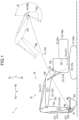
- FIG. 1 shows a work machine 10 according to the embodiment.
- the work machine 10 constitutes an automatic operation system 1 shown in FIG. 2 .
- the automatic operation system 1 includes the work machine 10, a posture detector 31, a reference position detector 32, a peripheral-object position detector 33, an input device 35, and a controller 50.
- Each of the posture detector 31, the reference position detector 32, the peripheral-object position detector 33, the input device 35, and the controller 50 may be disposed either inside the work machine 10 or outside the work machine 10 (for example, at a work site).
- the work machine 10 is a machine for performing work.
- the work machine 10 illustrated in FIG. 1 is a construction machine for performing construction work, specifically, an excavator.
- the work machine 10 is capable of being automatically operated.
- the work machine 10 may be capable of being operated by an operator boarding the work machine 10 or remotely operated at a place away from the work machine 10.
- the work machine 10 includes a machine body 10a, an attachment 15, a driving part 21 shown in FIG. 2 , and a driving control part 17.
- the machine body 10a is a main body part of the work machine 10.
- the machine body 10a includes a lower main body 11 and an upper turning body 13 shown in FIG. 1 .
- the lower main body 11 supports the upper turning body 13.
- the lower main body 11 illustrated in FIG. 1 is a lower traveling body capable of performing a traveling motion.
- the lower main body 11 includes a traveling body.
- the traveling body may be either a pair of crawlers illustrated in FIG. 1 or a plurality of wheels.
- the upper turning body 13 is mounted on the lower main body 11 capably of turning with respect to the lower main body 11.
- the upper turning body 13 includes an operation chamber 13a, in which an operator can perform operations for moving the work machine 10.
- the upper turning body 13 has an up-down direction Z and a front-rear direction X indicated by respective double-headed arrows in FIG. 1 .
- the up-down direction Z is a direction in which the central axis of the turning of the upper turning body 13 with respect to the lower main body 11 (turning center axis) extends.
- the up-down direction Z involves an upper side Za of the upper turning body 13 and a lower side Zb opposite thereto, the upper side Za being the opposite side to the lower main body 11 across the upper turning body 13.
- the up-down direction Z is, for example, a vertical direction.
- the up-down direction Z is orthogonal to a turning direction, and the upper turning body 13 turns in the turning direction with respect to the lower main body 11.
- the front-rear direction X is a direction orthogonal to each of the up-down direction Z and the turning direction, thus being equivalent to the turning radius direction.
- the front-rear direction X is the longitudinal direction of the attachment 15 when viewed along the up-down direction Z, that is, the direction in which the central axis of the attachment 15 with respect to the width direction thereof extends.
- the front-rear direction X involves a front side Xa of the upper turning body 13 and a rear side Xb opposite thereto, and the front side Xa is a side to which the attachment 15 protrudes from the upper turning body 13.
- the attachment 15, which is capable of performing a work motion for performing work, includes an attachment body 15a and a tip attachment 15d attached to the tip of the attachment body 15a.
- the attachment body 15a includes a boom 15b and an arm 15c, being operable to make motions to change the position of the control target part 16 of the tip attachment 15d.
- the boom 15b is attached to the upper turning body 13 capably of rising and falling with respect to the upper turning body 13, that is, capably of rotational movement in the up-down direction Z.
- the arm 15c is coupled to the boom 15b capably of rotational movement with respect to the boom 15b.
- the tip attachment 15d is attached to the tip of the attachment body 15a movably with respect to the attachment body 15a, specifically, coupled to the arm 15c capably of rotational movement with respect to the arm 15c.
- the tip attachment 15d shown in FIG. 1 is a bucket, attached to the tip of the attachment body 15a capably of making a capture motion and a release motion.
- the capture motion is a motion for work of capturing a work object WO, for example, work of scooping earth and sand
- the release motion is a motion for work of releasing the work object WO, for example, an earth removal work.
- the tip attachment 15d may be either a device for sandwiching a work object WO, such as a grapple or a nibra, or a device for crushing a work object WO, such as a breaker.
- the tip attachment 15d includes the control target part 16, which can be arbitrarily set in the tip attachment 15d.
- the control target part 16 may be either a connection part to be connected to the arm 15c of the tip attachment 15d as shown in FIG. 1 , namely, a proximal end part, or a distal end part of the tip attachment 15d, which is the end part opposite to the proximal end part.
- the work object WO is an object of work by the attachment 15 of the work machine 10. Examples of the work object WO include earth and sand, stone, wood, metal, waste, structure such as block, and the like.
- the driving part 21 drives a plurality of movable parts of the work machine 10 to make the work machine 10 perform motions.
- the driving part 21 drives the attachment 15.
- the driving part 21 includes a plurality of actuators corresponding to the plurality of movable parts, respectively.
- the plurality of actuators include a turning motor 21a and a plurality of hydraulic cylinders, which include a boom cylinder 21b, an arm cylinder 21c, and a tip attachment cylinder 21d.
- the turning motor 21a turns the upper turning body 13 with respect to the lower main body 11.
- the turning motor 21a may be either a hydraulic motor or an electric motor.
- the boom cylinder 21b is expanded and contracted to raise and lower the boom 15b with respect to the upper turning body 13.
- the arm cylinder 21c is expanded and contracted to rotationally move the arm 15c with respect to the boom 15b.
- the tip attachment cylinder 21d is expanded and contracted to rotationally move the tip attachment 15d with respect to the arm 15c.
- the driving part 21 may include an actuator (for example, a cylinder or a motor) for moving the movable part of the tip attachment 15d.
- the driving control part 17 controls the motion of the driving part 21, that is, controls the drive of the movable part. Specifically, the driving control part 17 controls respective motions of the turning motor 21a, the boom cylinder 21b, the arm cylinder 21c, and the tip attachment cylinder 21d. In the case where the driving part 21 includes a hydraulic actuator, the driving control part 17 includes a hydraulic circuit for controlling the hydraulic actuator. In the case where the driving part 21 includes an electric actuator, the driving control part 17 includes an electric circuit for controlling the electric actuator.
- the posture detector 31 detects the posture of the work machine 10. Specifically, the posture detector 31 acquires information about the posture of the attachment 15 and the posture of the upper turning body 13 with respect to the lower main body 11, namely, the turning posture.
- the posture detector 31 includes a turning sensor 31a, a boom sensor 31b, an arm sensor 31c, and a tip attachment sensor 31d.
- the turning sensor 31a detects the angle of the upper turning body 13 in the turning direction with respect to the lower main body 11 or the work site, namely, a turning angle.
- the boom sensor 31b detects the posture of the boom 15b.
- the boom sensor 31b detects the angle of the boom 15b in the rising and falling directions with respect to the horizontal direction or the upper turning body 13, namely, an inclination angle.
- the arm sensor 31c detects the posture of the arm 15c.
- the arm sensor 31c detects, for example, the angle of the arm 15c with respect to the horizontal direction or the boom 15b.
- the tip attachment sensor 31d detects the posture of the tip attachment 15d.
- the tip attachment sensor 31d detects, for example, the angle of the tip attachment 15d with respect to the horizontal direction or the arm 15c.
- the reference position detector 32 detects the position and orientation of a reference part, which is set in the work machine 10 shown in FIG. 1 , with respect to the work site.
- the reference part can be arbitrarily set, for example, being a specific part of the upper turning body 13 or the lower main body 11.
- the reference part may be either a part to be connected to the upper turning body 13 in the boom 15b, namely, a boom foot, or a part located on the turning central axis of the upper turning body 13.
- the reference position detector 31e may be included in a location positioning system.
- the location positioning system may be, for example, either a satellite positioning system such as GNSS (global navigation satellite system) or a system using a total station.
- the reference position detector 32 according to the present embodiment includes an antenna 32a as shown in FIG. 1 , being capable of communicating with the satellite positioning system.
- the peripheral-object position detector 33 acquires information on the position of a peripheral object that is an object present around the work position PW, namely, peripheral-object position information.
- peripheral-object position information include information on the position of the ground surface, information on the position of the work object WOa ( FIG. 4 ) having been released as described later, and information on the position of an obstacle or the like.
- the peripheral-object position detector 33 may include an imaging device.
- the imaging device examples include: a device for acquiring two-dimensional information of an imaging object, for example, a position and a shape in an image; a camera for generating two-dimensional information, namely, a monocular camera; a device for acquiring a distance image; a device for generating three-dimensional information of the imaging object, for example, a three-dimensional coordinate or a three-dimensional shape, based on the distance image; a device for generating three-dimensional information using a razer light, for example, a LIDAR (Light Detection and Ranging) or a TOF (Time of Flight) sensor; a device for detecting three-dimensional information using a radio wave, for example, a millimeter wave radar; and a stereo camera.
- the imaging device may generate three-dimensional information of the imaging object based on the distance image and the two-dimensional image.
- the peripheral-object position detector 33 may include a plurality of imaging devices.
- the input device 35 is a device that allows an operator to input information to the controller 50 through the input device 35. Specifically, the input device 35 allows an operation to be applied to the input device 35 by an operator, and inputs to the controller 50 an instruction corresponding to the applied operation. If disposed in the work machine 10, the input device 35 may be either a display device or an operation lever provided in the operation chamber 13a. The input device 35 may be a portable terminal, such as a tablet or a smartphone, or a personal computer. The input device 35 may be included in equipment installed outside the work machine 10, for example, a server. The input device 35 conducts communication with the controller 50, which communication may be either wireless communication or wired communication.
- the controller 50 includes a computer that executes input/output, operation (processing), storage of information (such as an operation result), and the like.
- the controller 50 includes a storage part that stores a program for providing the function of the controller 50, the program including an automatic operation program, and an operation part that executes the program stored in the storage part to achieve the function.
- the controller 50 may be either installed on the work machine 10, more specifically, at least one of the machine body 10a and the attachment 15, or provided outside the work machine 10, for example, in a server.
- to the controller 50 is input the information acquired by the detectors 31 to 33.
- To the controller 50 is input an instruction corresponding to the operation by the operator or other information from the input device 35.
- the controller 50 performs control for automatic operation of the work machine 10.
- the controller 50 inputs, to the driving control part 17, a command for making the driving part 21 drive to make the work machine 10 perform a predetermined motion.
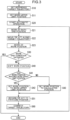
- the controller 50 includes a target trajectory setting part (target path correction part) 51, an automatic operation part 53, a work end judgment part 55, a work upper limit position setting part 61, a work position shifting part 63, and a target trajectory correction part (target path correction part) 65, which functions are provided by execution of the automatic operation program as shown in the flowchart of FIG. 3 .
- the target trajectory setting part 51 executes a target path setting step (step S10 shown in FIG. 3 ), specifically, sets a target path Pth shown in FIG. 1 and further a target trajectory Tr.
- the target path Pth is a target of the path of the control target part 16 of the tip attachment 15d.
- the target path Pth includes a plurality of target points P(i), where "i" is a natural number in a range from 1 to a predetermined maximum number N.
- Each of the target points P(i) is information about the target position of the control target part 16, specifically, a three-dimensional position coordinate.
- the target trajectory Rt is information including information on respective positions of the target points P(i) and information about the order of the plurality of target points P(i), namely, a so-called order set. Specifically, the target trajectory Rt is information about the target path Pth added with time information.
- the "time information" is, for example, a target section time Tst shown in below-described Table 1.
- the target section time Tst is a target value of the time by which the control target part 16 is to be moved through a section between two target points P(n) and P(n+1) that are adjacent to each other (sequential order).
- the controller 50 may include, in place of the target trajectory setting part 51, a target path setting part that sets only a target trajectory without the target section time Tst, namely, only the target path Pth.
- the parameter to represent the target trajectory Rt is, for example, one that allows the posture of the work machine 10 in each of the target points P(i) to be determined.
- the coordinate axis of the parameter and the origin thereof (reference position) are arbitrarily set.
- the origin may be set either in a work site or to an appropriate part of the work machine 10, for example, an appropriate part of the upper turning body 13.
- the origin may be set to either a part at which the upper turning body 13 and the boom 15b are interconnected, namely, a boom foot pin, or a part on the turning center axis of the upper turning body 13.
- the below table 1 shows an example of information given to each of the target points P(i) in the target trajectory Rt, the information including: a target coordinate Xt, which is a target of the coordinate corresponding to the coordinate axis in the front-rear direction X (X-coordinate); a target coordinate Zt, which is a target of the coordinate corresponding to the coordinate axis in the up-down direction Z (Z-coordinate); a target turning angle ⁇ t, which is the target of the turning angle of the upper turning body 13; the target section time Tst; and a target tip-attachment angle ⁇ t, which is the target of a tip-attachment angle ⁇ .
- a target coordinate Xt which is a target of the coordinate corresponding to the coordinate axis in the front-rear direction X (X-coordinate)
- a target coordinate Zt which is a target of the coordinate corresponding to the coordinate axis in the up-down direction Z (Z-coordinate
- a target turning angle ⁇ t which is
- the tip attachment angle ⁇ is an angle of the tip attachment 15d with respect to the up-down direction Z.
- the tip attachment angle ⁇ may be either of an angle of the tip attachment 15d with respect to the front-rear direction X, a rotation angle of the tip attachment 15d with respect to the arm 15c from the position at which the tip attachment 15d is fully opened, and an angle of the tip attachment 15d with respect to the horizontal direction.
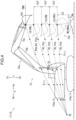
- the plurality of target points P(i) included in the target trajectory Rt include a path end position PE and a work position PW shown in FIG. 4 .
- the path end position PE and the work position PW are target points of respective positions at the opposite ends of the target trajectory Rt, respectively.
- one of the opposite ends of the target trajectory Rt is the path end position PE and the other is the work position PW.
- the work position PW is a position where the tip attachment 15d is to make the release motion, which is a motion for performing work of releasing the work object WO (e.g. soil removal).
- the work position PW is set to a position just above the ground, as shown in FIG. 1 .
- the work position PW alternatively, may be set to a position just above a non-illustrated container to accommodate the work object WO, for example, a loading platform of a transport vehicle.
- the path end position PE is a position away from the work position PW, allowed to be arbitrarily set.
- the path end position PE is a position where the tip attachment 15d is to make the capture motion.
- the path end position PE is set to a place where the work object WO is collected (e.g. soil sand, earth and sand pits, etc.).
- the controller 50 controls the driving control part 17 so as to move the tip attachment 15d along the target path Pth between the work position PW and the path end position PE.
- the controller 50 may control the driving control part 17 so as to turn the upper turning body 13 with respect to the lower main body 11 when the tip attachment 15d is moved along the target path Pth.
- There is a lifting turning motion that is a motion in which the tip attachment 15d is moved from a position at which the tip attachment 15d captures the work object WO (the path end position PE) to a position at which the tip attachment 15d releases the work object WO (the work position PW).
- the capture motion for capturing the work object WO, the lifting turning motion, the release motion for releasing the work object WO, and the return turning motion constitute a series of motions in one cycle, and the controller 50 controls the driving control part 17 to make the series of motions performed repeatedly, that is, to make the series of motions performed over a plurality of cycles.
- the turning of the upper turning body 13 with respect to the lower main body 11 along with the movement of the tip attachment 15d along the target path Pth is optional.
- the turning of the upper turning body 13 do not have to be included in the "series of motions".
- the series of motions may be composed of only a motion in which the control target part 16 of the tip attachment 15d is moved only in at least one direction of the front-rear direction X and the up-down direction Z with no movement of the control target part 16 in the turning direction.
- the target trajectory setting part 51 of the controller 50 sets a reference target trajectory Rtb serving as a reference for the target trajectory Rt before the work by the automatic operation of the work machine 10 (work by the tip attachment 15d) is performed (step S10 in FIG. 3 ).
- the reference target trajectory Rtb may be either set by teaching and input to the target trajectory setting part 51 or set by a method other than the teaching (e.g. input of a numerical value by an operator through an input device 35).
- the teaching is performed as follows.
- An operator boards the work machine 10 to operate the work machine 10 or remotely operates the work machine 10 to thereby move the control target part 16 at a speed that is desired to be set for the reference target trajectory Rtb along a path that is desired to be set as the reference target trajectory Rtb.
- the target trajectory setting part 51 stores the trajectory along which the control target part 16 has been actually moved by the operation of the operator, and sets the stored trajectory to a reference target trajectory Rtb.
- the position coordinate of the control target part 16 is calculated and stored at each predetermined time (for example, every one second).
- the position coordinates of the control target part 16 can be calculated based on the posture of the work machine 10 detected by the posture detector 31.
- the thus stored position coordinates are set to respective position coordinates of the plurality of target points P(i), respectively.
- the automatic operation part 53 of the controller 50 executes the automatic operation of the work machine 10 (automatic operation step; step S20, S21, S22, S23, and S51 in FIG. 3 ). More specifically, the automatic operation part 53 automatically controls the operation of the work machine 10 so as to make the control target part 16 of the tip attachment 15d moved along the target path Pth (according to the target trajectory Rt) to thereby make the series of motions performed and further so as to make the series of motions repeated over the plurality of cycles.
- the target of the automatic control by the automatic operation part 53 may be either only the motion of the attachment 15 or both the motion of the attachment 15 and the turning motion of the upper turning body 13 with respect to the lower main body 11.
- the automatic operation part 53 generates a command for the automatic control and inputs the command to the driving control part 17, thereby operating the driving part 21.
- the automatic operation part 53 generates the command based on the value detected by the posture detector 31.
- the automatic operation part 53 performs the automatic operation of the work machine 10 so as to make the work machine 10 perform the series of motions constituted by the motion of capturing the work object WO, the lifting turning motion, the motion of releasing the work object WO and the return turning motion over the plurality of cycles.
- the automatic operation part 53 makes the motion of capturing the work object WO performed with the control target part 16 of the tip attachment 15d located at the path end position PE (step S21 in FIG. 3 ). After the end of the work at the path end position PE, the automatic operation part 53 operates the attachment 15 to move the control target part 16 from the path end position PE to the work position PW along the target trajectory Rt (step S22).
- the automatic operation part 53 makes the motion of releasing the work object WO performed with the control target part 16 located at the work position PW (step S23). After the end of the work at the work position PW, the automatic operation part 53 operates the attachment 15 so as to move the control target part 16 from the work position PW to the path end position PE along the target trajectory Rt.
- the automatic operation part 53 makes the attachment 15 repeat the series of motions (steps S21, S22, S23, and S51). In the example shown in FIG.
- a return motion control for returning the tip attachment 15d including the control target part 16 to the path end position PE is performed after the shift of the work position PW (steps S40 to S43) as described later; however, the return motion control (step S30) may be performed before the shift of the work position PW (step S40).
- the work end judgment part 55 of the controller 50 judges whether or not a work end condition is satisfied after the end of the release motion at the work position PW (work end judgment step; step S30 in FIG. 3 ).
- the work end condition is preset as a condition for ending the work by the series of motions over the plurality of cycles.
- the work end condition is a condition for ending the work that is performed by the execution of the series of motions constituted by the motion of capturing the work object WO, the lifting turning motion, the motion of releasing the work object WO, and the return turning motion over the plurality of cycles, i.e., by the repeat of the series of motions.
- the work end condition can be variously set.
- the work end condition may either be composed of only a single unit condition or include a plurality of unit conditions. When including the plurality of unit conditions, the work end condition may require that at least one of the plurality of unit conditions be satisfied or that two or more (e.g. all) of the plurality of unit conditions be satisfied.
- the work end condition includes the condition that the work position PW shown in FIG. 4 reaches a work upper limit position PWU that is set by the work upper limit position setting part 61 of the controller 50 shown in FIG. 2 . More specifically, in response to the end of the series of motions, the work position shifting part 63 of the controller 50 shifts the work position PW, and the work end condition includes a condition that the work position PW thus shifted at any time reaches the work upper limit position PWU, that is, a condition that the work position PW calculated by the work position shifting part 63 is the work upper limit position PWU or a position on the upper side of the work upper limit position PWU.
- the work end condition may include a condition different from the work position condition in place of or in addition to the work upper limit position condition that the work position PW reaches the work upper limit position PWU.
- the work end condition may include that the number of times by which the series of motions have been performed (the number of cycles) reaches a "preset number of times" that is set in advance.
- the work end condition alternatively, may include that the work position PW has reached a "preset position" different from the work upper limit position PWU.
- the "preset number of times" and the "preset position" are set in the controller 50 in advance of the judgment of the work end condition by the work end judgment part 55.
- step S30 the automatic operation part 53 makes the work by the series of motions over the plurality of cycles ended.
- the work end judgment part 55 judges that the work end condition is not satisfied (NO in step S30)
- the automatic operation part 53 makes the work machine 10 continue the work by the series of motions.
- the work upper limit position setting part 61 of the controller 50 sets the work upper limit position PWU (work upper limit position setting step; step S11 in FIG. 3 ).
- the work upper limit position PWU is the upper limit of the work position PW, more specifically, the limit of the upper side Za of a range within which the work position PW can be set.
- the work upper limit position setting part 61 may set the work upper limit position PWU in various ways.
- the work upper limit position setting part 61 may set the work upper limit position PWU based on the position at which the tip attachment 15d is actually located, that is, the position designated by teaching. For example, when an operator positions the tip attachment 15d at a position to which the operator desires to set the work upper limit position PWU by the operation of the work machine 10, the work upper limit position setting part 61 may set the position of the control target part 16 of the tip attachment 15d as the work upper limit position PWU. According to this example, the work upper limit position PWU can be reliably set at a position that the tip attachment 15d can physically reach. Besides, the operator can easily (sensuously) set the work upper limit position PWU.
- the teaching may be either a teaching only for the purpose of setting the work upper limit position PWU or a teaching for setting the reference target trajectory Rtb and also for the setting of the work upper limit position PWU.
- the work upper limit position setting part 61 can set the work position PW included in the reference target trajectory Rtb as the work upper limit position PWU.
- the work upper limit position setting part 61 may set the position designated through a method other than the teaching, for example, an input of a numerical value by an operator, as the work upper limit position PWU.
- the work upper limit position PWU may be set at various positions.
- the work upper limit position PWU is set at such a position that the amount of the work object WO released in the series of motions is appropriate.
- the work upper limit position PWU may be set at such a position as to restrain the work object WO loaded in the container from excess or deficiency.
- the work position shifting part 63 of the controller 50 makes the shift of the work position PW, that is, the revision thereof (work position shifting step; step S40 in FIG. 3 ).
- the work position shifting part 63 sets the work position PW in the series of motions that is firstly performed after setting the work upper limit position PWU by the work upper limit position setting part 61, i.e., the series of motions of the first cycle, as the initial work position PW1.
- the work position shifting part 63 sets the initial work position PW1 to a position on the lower side Zb of the work upper limit position PWU.
- the work position shifting part 63 preferably sets the initial work position PW1 in such a position that the work object WO released from the initial work position PW1 can be restrained from falling vigorously, that is, such a position that the falling speed and impact of the work object WO can be reduced.
- the work position shifting part 63 may set the initial work position PW1 based on the information acquired by the peripheral-object position detector 33.
- the work position shifting part 63 may set the initial work position PW1 based on information, such as a numerical value, input through the input device 35 by an operator.
- the work upper limit position PWU alternatively, may be a value stored in advance in the controller 50, namely, an initial value.
- the work position shifting part 63 shifts the work position PW in the up-down direction Z, that is, changes the height of the work position PW, in accordance with the advance of the series of motions over the plurality of cycles.
- the work position shifting part 63 may shift the work position PW either every time the series of motions of one cycle ends or every time the series of motions of a predetermined number of cycles ends. In the latter case, the predetermined number of cycles may be either constant or varied.
- the work position shifting part 63 may shift the work position PW not only in the up-down direction Z but also in at least one of the front-rear direction X and the turning direction.
- the work position shifting part 63 can restrain the tip attachment 15d from coming into contact with a released work object WOa which is a work object WO having already been released from the tip attachment 15d, for example, a stacked work object WO.
- a released work object WOa which is a work object WO having already been released from the tip attachment 15d, for example, a stacked work object WO.
- the work position shifting part 63 may shift the work position PW to the lower side Zb.
- the work position shifting part 63 may shift the work position PW to the lower side Zb in accordance with the reduction.
- the manner of the shift of the work position PW by the work position shifting part 63 is not limited. Below are shown examples of the shift.
- the work position shifting part 63 may shift the work position PW by a constant shift amount Csf stored in the controller 50.
- the work position PW can be shifted by the setting of a simple parameter, that is, the setting of the shift amount Csf.
- the work position shifting part 63 may set the work position PW based on the information acquired by the peripheral-object position detector 33, for example, information on the position of an object present around the work position PW, which is, for example, the work position PW immediately after the performance of the previous work.
- the work position shifting part 63 preferably sets (shifts) the work position PW so as to prevent the tip attachment 15d from coming into contact with an obstacle.
- the "obstacle” is, for example, the ground, a loading platform, or a released work object WOa.
- the work position shifting part 63 shifts the work position PW to the upper side Za with the control target part 16 set at the proximal end of the tip attachment 15d
- the work position shifting part 63 sets the work position PW at the position on the upper side Za of the top (the end on the upper side Za) of the released work object WOa by the sum of an effective length LE of the tip attachment 15d and a margin height Hm.
- the effective length LE of the tip attachment 15d is, for example, the length of the tip attachment 15d in the up-down direction Z in the posture with the maximum length of the tip attachment 15d in the up-down direction Z.
- the margin height Hm is set, for example, to be greater than the height of the work object WO that is expected to be stacked on the released work object WOa after the work object WO is released from the tip attachment 15d.
- Example D1 and Example D2 may be combined with each other.
- the work position shifting part 63 may set the initial work position PW1 based on the position information acquired by the peripheral-object position detector 33 and thereafter shift the work position PW by the shift amount Csf in the series of motions of the second and subsequent cycles.
- the work position shifting part 63 sets the work position PW based on the work upper limit position PWU set by the work upper limit position setting part 61, that is, within the range in which the work position PW is permitted to be set.
- the work position shifting part 63 does not set the work position PW in a region on the upper side Za of the work upper limit position PWU, that is, a region in which the work position PW is prohibited to be set.
- the work position PW is thus limited to the position of the work upper limit position PWU or a position on the lower side Zb thereof.
- the work position shifting part 63 sets the work position PW to the work upper limit position PWU (step S42). In other words, the work position shifting part 63 corrects the work position PW to be shifted, from the calculated position to the work upper limit position PWU.
- the automatic operation part 53 may end the series of motions over the plurality of cycles after the tip attachment 15d makes a motion for work, namely, release motion, at the work position PW thus corrected to the work upper limit position PWU (YES in step S30).
- the series of motions of the plurality of cycles may be ended without the correction of the work position PW to the work upper limit position PWU (YES in step S30).
- the work position shifting part 63 determines the calculated work position PW (step S40) as the actual work position PW as it is (step S43).
- the target trajectory correction part (target path correction part) 65 of the controller 50 corrects the target path Pth in response to the shift of the work position PW, that is, corrects the target trajectory Rt in the present embodiment (target trajectory correction step; step S60 in FIG. 3 ).
- the target trajectory correction part 65 corrects the section between the path end position PE and the work position PW in the target trajectory Rt.
- the target trajectory correction part 65 may make either both the correction of the target path Pth and the correction of the target movement speed of the control target part 16 (for example, the correction of the target section time Tst) or only the connection of the target path Pth out of the target path Pth and the target movement speed.
- the target trajectory correction part 65 may correct the target trajectory Rt based on the target path Pth of the reference target trajectory Rtb and the work position PW shifted by the work position shifting part 63.
- the target trajectory correction part 65 may correct the target trajectory Rt so as to smoothly interjoin the path end position PE and the shifted work position PW.
- the target trajectory correction part 65 may correct the target trajectory Rt so as to render the shape of the target path Pth of the corrected target trajectory Rt similar to that of the target path Pth of the reference target trajectory Rtb.
- the above embodiments may be variously modified.
- the number of components (including modification examples) of the above embodiment may be changed, and some of the components may be omitted.
- modifications of the embodiments described above may be combined in various ways.
- fixing, coupling, or the like of the components may be performed either directly or indirectly.
- the connection of components shown in FIG. 2 may be varied.
- the inclusion relationship of the components may be variously changed.
- the components described as components included in a certain generic component may be included in not the generic component but other component.
- those described as a plurality of members and portions different from each other may be modified to one member or a portion.
- a component described as a single member or a single part may be divided into a plurality of members or parts different from each other.
- various parameters (such as the set values, ranges, etc. of the margin height Hm and the like) may be either set in advance in the controller 50 or directly set by the manual operation of a worker.
- Various parameters may be calculated by the controller 50 based on either information set by the manual operation of the worker or information detected by the sensor such as an imaging device).
- various parameters may be either of non-changed, manually changed and automatically changed the controller 50 in accordance with some conditions.
- the order of the steps of the flowchart shown in FIG. 3 may be changed, and a part of the steps may be omitted.
- each component may have only a part of the feature thereof as to action function, arrangement, shape, actuation, or the like.
- an automatic operation system As has been described, there are provided an automatic operation system, a work machine, and an automatic operation program, each of which is capable of making a tip attachment of a work machine perform an appropriate series of motions.
- an automatic operation system that includes a machine body of a work machine, an attachment, and a controller.
- the attachment is attached to the machine body capably of making a motion for performing work.
- the attachment includes an attachment body and a tip attachment.
- the tip attachment includes a control target part and is attached to a tip of the attachment body capably of making a release motion for performing work of releasing a work object.
- the attachment body is operable to change a position of the control target part.
- the controller includes a target path setting part, an automatic operation part, a work upper limit position setting part, and a work position shifting part.
- the target path setting part sets a target path, which is a target of a path along which the control target part is to be moved between a work position where the tip attachment makes the release motion and a path end position away from the work position.
- the automatic operation part automatically controls the motion of the attachment so as to make the attachment perform a series of motions over a plurality of cycles, the series of motions including a motion of moving the control target part along the target path.
- the work upper limit position setting part sets a work upper limit position that is an upper limit of the work position.
- the work position shifting part shifts the work position in an up-down direction in accordance with an advance of the series of motions over the plurality of cycles.
- the work position shifting part shifts the work position to the work upper limit position or within a range on a lower side of the work upper limit position, and sets the work position in the series of motions in a first cycle after setting of the work upper limit position by the work upper limit position setting part among the plurality of cycles to a position on the lower side of the work upper limit position.
- the work position shifting part which sets the work position to the work upper limit position or a position on the lower side of the work upper limit position, can reduce the force of falling of the work object having been released from the tip attachment, as compared with a case where the work position is set to a position on the upper side of the work upper limit position.
- the work position in the series of motions of the tip attachment of the work machine is, thus, appropriately set. This enables, for example, the falling speed of the work object having been released from the tip attachment or the impact on the dropped work object to be reduced.
- the work position shifting part is configured to shift the work position to an upper side in accordance with the advance of the series of motions over the plurality of cycles. This can restrain the tip attachment from interfering with a work object, in the case where the work object (for example, a work object having been released) is stacked along with the advance of the series of motions.
- the work upper limit position setting part is configured to set the work upper limit position based on a position at which the tip attachment is actually located. This allows an operator to set the work upper limit position with a simple operation of moving the work machine to locate the tip attachment at a desired position, which is a position desired to be set as the work upper limit position. The operator, thus, is enabled to set the work upper limit position easily, e.g., sensuously.
- the automatic operation system further includes a peripheral-object position detector that acquires peripheral-object position information that is information on a position of an object present around the work position, wherein the work position shifting part is configured to shift the work position based on the peripheral-object position information acquired by the peripheral-object position detector.
- the thus configured work position shifting part can set an appropriate work position based on the peripheral-object position information acquired by the peripheral-object position detector, thereby enabling the tip attachment to make a motion for work with high efficiency.
- the tip attachment that releases the work object at the work position can be restrained from interfering with an obstacle which is, for example, the released work object, the ground, a loading platform, or the like.
- the work position shifting part may be configured to shift the work position by a preset constant shift amount in accordance with the advance of the series of motions over the plurality of cycles. This enables the work position to be shifted by setting of a simple parameter.
- the controller further includes a work end judgment part, which judges whether or not a preset work end condition is satisfied, and the automatic operation part is configured to end the series of motions when the work end condition is judged to be satisfied.
- the work end condition is a preset condition for ending the series of motions over the plurality of cycles, including a condition that the work position has reached the work upper limit position.
- the thus configured automatic operation part can make the work by the series of motions ended at a preferable timing when the work position reaches the work upper limit position.
- a work machine including a machine body, an attachment, and a controller.
- the attachment is attached to the machine body capably of making a motion for performing work.
- the attachment includes an attachment body and a tip attachment.
- the tip attachment includes a control target part and is attached to a tip of the attachment body capably of making a release motion for performing work of releasing a work object.
- the attachment body is operable to change a position of the control target part.
- the controller includes a target path setting part, an automatic operation part, a work upper limit position setting part, and a work position shifting part.
- the target path setting part sets a target path, which is a target of a path along which the control target part is to be moved between a work position where the tip attachment makes the release motion and a path end position away from the work position.
- the automatic operation part automatically controls the motion of the attachment so as to make the attachment perform a series of motions over a plurality of cycles, the series of motions including a motion of moving the control target part along the target path.
- the work upper limit position setting part sets a work upper limit position that is an upper limit of the work position.
- the work position shifting part shifts the work position in an up-down direction in accordance with an advance of the series of motions over the plurality of cycles.
- the work position shifting part shifts the work position to the work upper limit position or within a range on a lower side of the work upper limit position, and sets the work position in the series of motions in a first cycle after setting of the work upper limit position by the work upper limit position setting part among the plurality of cycles to a position on a lower side of the work upper limit position.
- an automatic operation program used for a work machine including a machine body and an attachment.
- the attachment is attached to the machine body capably of making a motion for performing work.
- the attachment includes an attachment body and a tip attachment.
- the tip attachment includes a control target part and is attached to a tip of the attachment body capably of making a release motion for performing work of releasing a work object.
- the attachment body is operable to change a position of the control target part.
- the automatic operation program makes a computer execute a target path setting step, an automatic operation step, a work upper limit position setting step, and a work position shifting step.
- the target path setting step is a step of setting a target path, which is a target of a path along which the control target part is to be moved between a work position where the tip attachment makes the release motion and a path end position away from the work position.
- the automatic operation step is a step of automatically controlling a motion of the attachment so as to make the attachment perform a series of motions over a plurality of cycles, the series of motions including a motion of moving the control target part along the target path.
- the work upper limit position setting step is a step of setting a work upper limit position that is an upper limit of the work position.
- the work position shifting step is a step of shifting the work position in an up-down direction in accordance with an advance of the series of motions over the plurality of cycles.
- the work position shifting step includes shifting the work position to the work upper limit position or within a range on a lower side of the work upper limit position, and setting the work position in the series of motions in a first cycle after setting of the work upper limit position in the work upper limit position setting step among the plurality of cycles to a position on a lower side of the work upper limit position.
- the automatic operation program can be read by the computer.
Landscapes
- Engineering & Computer Science (AREA)
- Mechanical Engineering (AREA)
- Mining & Mineral Resources (AREA)
- Civil Engineering (AREA)
- General Engineering & Computer Science (AREA)
- Structural Engineering (AREA)
- Life Sciences & Earth Sciences (AREA)
- General Life Sciences & Earth Sciences (AREA)
- Paleontology (AREA)
- Operation Control Of Excavators (AREA)
Abstract
Description
- The present invention relates to an automatic operation system, a work machine, and an automatic operation program for a work machine.
-
Patent Literature 1 discloses a work machine capable of being automatically operated. A series of motions to be performed by the work machine, which are motions making a circle from excavation to soil release in the above literature, are set (taught) to a controller. The controller executes an automatic operation for making the work machine perform the series of motions. - Patent Literature 1:
Japanese Unexamined Patent Publication No. Hei 11-264155 - In the case where the series of motions include a motion of releasing a work object, which is releasing earth and soil in the above literature, the motion is desired to be made at an appropriate height.
- It is an object of the present invention to provide an automatic operation system, a work machine, and an automatic operation program, each of which is capable of making a tip attachment of a work machine perform an appropriate series of motions.
- Provided is an automatic operation system that includes a machine body of a work machine, an attachment, and a controller. The attachment is attached to the machine body capably of making a motion for performing work. The attachment includes an attachment body and a tip attachment. The tip attachment includes a control target part and is attached to a tip of the attachment body capably of making a release motion for performing work of releasing a work object. The attachment body is operable to change a position of the control target part. The controller includes a target path setting part, an automatic operation part, a work upper limit position setting part, and a work position shifting part. The target path setting part sets a target path, which is a target of a path along which the control target part is to be moved between a work position where the tip attachment makes the release motion and a path end position away from the work position. The automatic operation part automatically controls the motion of the attachment so as to make the attachment perform a series of motions over a plurality of cycles, the series of motions including a motion of moving the control target part along the target path. The work upper limit position setting part sets a work upper limit position that is an upper limit of the work position. The work position shifting part shifts the work position in an up-down direction in accordance with an advance of the series of motions over the plurality of cycles. The work position shifting part shifts the work position to the work upper limit position or within a range on a lower side of the work upper limit position, and sets the work position in the series of motions in a first cycle after setting of the work upper limit position by the work upper limit position setting part among the plurality of cycles to a position on a lower side of the work upper limit position.
- Also provided is a work machine including a machine body, an attachment, and a controller. The attachment is attached to the machine body capably of making a motion for performing work. The attachment includes an attachment body and a tip attachment. The tip attachment includes a control target part and is attached to a tip of the attachment body capably of making a release motion for performing work of releasing a work object. The attachment body is operable to change a position of the control target part. The controller includes a target path setting part, an automatic operation part, a work upper limit position setting part, and a work position shifting part. The target path setting part sets a target path, which is a target of a path along which the control target part is to be moved between a work position where the tip attachment makes the release motion and a path end position away from the work position. The automatic operation part automatically controls the motion of the attachment so as to make the attachment perform a series of motions over a plurality of cycles, the series of motions including a motion of moving the control target part along the target path. The work upper limit position setting part sets a work upper limit position that is an upper limit of the work position. The work position shifting part shifts the work position in an up-down direction in accordance with an advance of the series of motions over the plurality of cycles. The work position shifting part shifts the work position to the work upper limit position or within a range on a lower side of the work upper limit position, and sets the work position in the series of motions in a first cycle after setting of the work upper limit position by the work upper limit position setting part among the plurality of cycles to a position on a lower side of the work upper limit position.
- Also provided is an automatic operation program used for a work machine including a machine body and an attachment. The attachment is attached to the machine body capably of making a motion for performing work. The attachment includes an attachment body and a tip attachment. The tip attachment includes a control target part and is attached to a tip of the attachment body capably of making a release motion for performing work of releasing a work object. The attachment body is operable to change a position of the control target part. The automatic operation program makes a computer execute a target path setting step, an automatic operation step, a work upper limit position setting step, and a work position shifting step. The target path setting step is a step of setting a target path, which is a target of a path along which the control target part is to be moved between a work position where the tip attachment makes the release motion and a path end position away from the work position. The automatic operation step is a step of automatically controlling a motion of the attachment so as to make the attachment perform a series of motions over a plurality of cycles, the series of motions including a motion of moving the control target part along the target path. The work upper limit position setting step is a step of setting a work upper limit position that is an upper limit of the work position. The work position shifting step is a step of shifting the work position in an up-down direction in accordance with an advance of the series of motions over the plurality of cycles. The work position shifting step includes shifting the work position to the work upper limit position or within a range on a lower side of the work upper limit position, and setting the work position in the series of motions in a first cycle after setting of the work upper limit position in the work upper limit position setting step among the plurality of cycles to a position on a lower side of the work upper limit position.
- Also provided is a recording medium on which the automatic operation program is recorded. The automatic operation program can be read by the computer.
-
-
FIG. 1 is a side view of a work machine according to an embodiment of the present invention. -
FIG. 2 is a block diagram showing an automatic operation system according to the embodiment. -
FIG. 3 is a flowchart showing a control action to be executed by the automatic operation system. -
FIG. 4 is a side view showing an example of a work position set by the automatic operation system. - There will be described an embodiment of the present invention with reference to
FIGS. 1 to 4 . -
FIG. 1 shows awork machine 10 according to the embodiment. Thework machine 10 constitutes anautomatic operation system 1 shown inFIG. 2 . Theautomatic operation system 1 includes thework machine 10, aposture detector 31, areference position detector 32, a peripheral-object position detector 33, aninput device 35, and acontroller 50. Each of theposture detector 31, thereference position detector 32, the peripheral-object position detector 33, theinput device 35, and thecontroller 50 may be disposed either inside thework machine 10 or outside the work machine 10 (for example, at a work site). - The
work machine 10 is a machine for performing work. Thework machine 10 illustrated inFIG. 1 is a construction machine for performing construction work, specifically, an excavator. Thework machine 10 is capable of being automatically operated. Thework machine 10 may be capable of being operated by an operator boarding thework machine 10 or remotely operated at a place away from thework machine 10. - The
work machine 10 includes amachine body 10a, anattachment 15, a drivingpart 21 shown inFIG. 2 , and adriving control part 17. - The
machine body 10a is a main body part of thework machine 10. Themachine body 10a includes a lowermain body 11 and an upper turningbody 13 shown inFIG. 1 . The lowermain body 11 supports theupper turning body 13. The lowermain body 11 illustrated inFIG. 1 is a lower traveling body capable of performing a traveling motion. Specifically, the lowermain body 11 includes a traveling body. The traveling body may be either a pair of crawlers illustrated inFIG. 1 or a plurality of wheels. Theupper turning body 13 is mounted on the lowermain body 11 capably of turning with respect to the lowermain body 11. Theupper turning body 13 includes anoperation chamber 13a, in which an operator can perform operations for moving thework machine 10. - The
upper turning body 13 has an up-down direction Z and a front-rear direction X indicated by respective double-headed arrows inFIG. 1 . The up-down direction Z is a direction in which the central axis of the turning of theupper turning body 13 with respect to the lower main body 11 (turning center axis) extends. The up-down direction Z involves an upper side Za of theupper turning body 13 and a lower side Zb opposite thereto, the upper side Za being the opposite side to the lowermain body 11 across theupper turning body 13. The up-down direction Z is, for example, a vertical direction. The up-down direction Z is orthogonal to a turning direction, and theupper turning body 13 turns in the turning direction with respect to the lowermain body 11. The front-rear direction X is a direction orthogonal to each of the up-down direction Z and the turning direction, thus being equivalent to the turning radius direction. The front-rear direction X is the longitudinal direction of theattachment 15 when viewed along the up-down direction Z, that is, the direction in which the central axis of theattachment 15 with respect to the width direction thereof extends. The front-rear direction X involves a front side Xa of theupper turning body 13 and a rear side Xb opposite thereto, and the front side Xa is a side to which theattachment 15 protrudes from theupper turning body 13. - The
attachment 15, which is capable of performing a work motion for performing work, includes anattachment body 15a and atip attachment 15d attached to the tip of theattachment body 15a. - The
attachment body 15a includes aboom 15b and anarm 15c, being operable to make motions to change the position of thecontrol target part 16 of thetip attachment 15d. Theboom 15b is attached to theupper turning body 13 capably of rising and falling with respect to theupper turning body 13, that is, capably of rotational movement in the up-down direction Z. Thearm 15c is coupled to theboom 15b capably of rotational movement with respect to theboom 15b. - The
tip attachment 15d is attached to the tip of theattachment body 15a movably with respect to theattachment body 15a, specifically, coupled to thearm 15c capably of rotational movement with respect to thearm 15c. Thetip attachment 15d shown inFIG. 1 is a bucket, attached to the tip of theattachment body 15a capably of making a capture motion and a release motion. The capture motion is a motion for work of capturing a work object WO, for example, work of scooping earth and sand, and the release motion is a motion for work of releasing the work object WO, for example, an earth removal work. Thetip attachment 15d, alternatively, may be either a device for sandwiching a work object WO, such as a grapple or a nibra, or a device for crushing a work object WO, such as a breaker. Thetip attachment 15d includes thecontrol target part 16, which can be arbitrarily set in thetip attachment 15d. For example, thecontrol target part 16 may be either a connection part to be connected to thearm 15c of thetip attachment 15d as shown inFIG. 1 , namely, a proximal end part, or a distal end part of thetip attachment 15d, which is the end part opposite to the proximal end part. The work object WO is an object of work by theattachment 15 of thework machine 10. Examples of the work object WO include earth and sand, stone, wood, metal, waste, structure such as block, and the like. - The driving
part 21 drives a plurality of movable parts of thework machine 10 to make thework machine 10 perform motions. The drivingpart 21 drives theattachment 15. The drivingpart 21 includes a plurality of actuators corresponding to the plurality of movable parts, respectively. The plurality of actuators include a turningmotor 21a and a plurality of hydraulic cylinders, which include aboom cylinder 21b, anarm cylinder 21c, and atip attachment cylinder 21d. The turningmotor 21a turns theupper turning body 13 with respect to the lowermain body 11. The turningmotor 21a may be either a hydraulic motor or an electric motor. Theboom cylinder 21b is expanded and contracted to raise and lower theboom 15b with respect to theupper turning body 13. Thearm cylinder 21c is expanded and contracted to rotationally move thearm 15c with respect to theboom 15b. Thetip attachment cylinder 21d is expanded and contracted to rotationally move thetip attachment 15d with respect to thearm 15c. In the case where thetip attachment 15d itself includes a movable part, for example, a part capable of making a motion of holding an object, the drivingpart 21 may include an actuator (for example, a cylinder or a motor) for moving the movable part of thetip attachment 15d. - The driving
control part 17 controls the motion of the drivingpart 21, that is, controls the drive of the movable part. Specifically, the drivingcontrol part 17 controls respective motions of the turningmotor 21a, theboom cylinder 21b, thearm cylinder 21c, and thetip attachment cylinder 21d. In the case where the drivingpart 21 includes a hydraulic actuator, the drivingcontrol part 17 includes a hydraulic circuit for controlling the hydraulic actuator. In the case where the drivingpart 21 includes an electric actuator, the drivingcontrol part 17 includes an electric circuit for controlling the electric actuator. - The
posture detector 31 detects the posture of thework machine 10. Specifically, theposture detector 31 acquires information about the posture of theattachment 15 and the posture of theupper turning body 13 with respect to the lowermain body 11, namely, the turning posture. - In the present embodiment, the
posture detector 31 includes a turningsensor 31a, aboom sensor 31b, anarm sensor 31c, and atip attachment sensor 31d. - The turning
sensor 31a detects the angle of theupper turning body 13 in the turning direction with respect to the lowermain body 11 or the work site, namely, a turning angle. Theboom sensor 31b detects the posture of theboom 15b. For example, theboom sensor 31b detects the angle of theboom 15b in the rising and falling directions with respect to the horizontal direction or theupper turning body 13, namely, an inclination angle. Thearm sensor 31c detects the posture of thearm 15c. Thearm sensor 31c detects, for example, the angle of thearm 15c with respect to the horizontal direction or theboom 15b. Thetip attachment sensor 31d detects the posture of thetip attachment 15d. Thetip attachment sensor 31d detects, for example, the angle of thetip attachment 15d with respect to the horizontal direction or thearm 15c. - The
reference position detector 32 detects the position and orientation of a reference part, which is set in thework machine 10 shown inFIG. 1 , with respect to the work site. The reference part can be arbitrarily set, for example, being a specific part of theupper turning body 13 or the lowermain body 11. Specifically, the reference part may be either a part to be connected to theupper turning body 13 in theboom 15b, namely, a boom foot, or a part located on the turning central axis of theupper turning body 13. The reference position detector 31e may be included in a location positioning system. The location positioning system may be, for example, either a satellite positioning system such as GNSS (global navigation satellite system) or a system using a total station. Thereference position detector 32 according to the present embodiment includes anantenna 32a as shown inFIG. 1 , being capable of communicating with the satellite positioning system. - The peripheral-
object position detector 33 acquires information on the position of a peripheral object that is an object present around the work position PW, namely, peripheral-object position information. Examples of the peripheral-object position information include information on the position of the ground surface, information on the position of the work object WOa (FIG. 4 ) having been released as described later, and information on the position of an obstacle or the like. The peripheral-object position detector 33 may include an imaging device. Examples of the imaging device include: a device for acquiring two-dimensional information of an imaging object, for example, a position and a shape in an image; a camera for generating two-dimensional information, namely, a monocular camera; a device for acquiring a distance image; a device for generating three-dimensional information of the imaging object, for example, a three-dimensional coordinate or a three-dimensional shape, based on the distance image; a device for generating three-dimensional information using a razer light, for example, a LIDAR (Light Detection and Ranging) or a TOF (Time of Flight) sensor; a device for detecting three-dimensional information using a radio wave, for example, a millimeter wave radar; and a stereo camera. The imaging device may generate three-dimensional information of the imaging object based on the distance image and the two-dimensional image. The peripheral-object position detector 33 may include a plurality of imaging devices. - The
input device 35 is a device that allows an operator to input information to thecontroller 50 through theinput device 35. Specifically, theinput device 35 allows an operation to be applied to theinput device 35 by an operator, and inputs to thecontroller 50 an instruction corresponding to the applied operation. If disposed in thework machine 10, theinput device 35 may be either a display device or an operation lever provided in theoperation chamber 13a. Theinput device 35 may be a portable terminal, such as a tablet or a smartphone, or a personal computer. Theinput device 35 may be included in equipment installed outside thework machine 10, for example, a server. Theinput device 35 conducts communication with thecontroller 50, which communication may be either wireless communication or wired communication. - The
controller 50 includes a computer that executes input/output, operation (processing), storage of information (such as an operation result), and the like. For example, thecontroller 50 includes a storage part that stores a program for providing the function of thecontroller 50, the program including an automatic operation program, and an operation part that executes the program stored in the storage part to achieve the function. Thecontroller 50 may be either installed on thework machine 10, more specifically, at least one of themachine body 10a and theattachment 15, or provided outside thework machine 10, for example, in a server. As shown inFIG. 2 , to thecontroller 50 is input the information acquired by thedetectors 31 to 33. To thecontroller 50 is input an instruction corresponding to the operation by the operator or other information from theinput device 35. Thecontroller 50 performs control for automatic operation of thework machine 10. Specifically, thecontroller 50 inputs, to the drivingcontrol part 17, a command for making the drivingpart 21 drive to make thework machine 10 perform a predetermined motion. - Specifically, as shown in
FIG. 2 , thecontroller 50 includes a target trajectory setting part (target path correction part) 51, anautomatic operation part 53, a workend judgment part 55, a work upper limitposition setting part 61, a workposition shifting part 63, and a target trajectory correction part (target path correction part) 65, which functions are provided by execution of the automatic operation program as shown in the flowchart ofFIG. 3 . - The target
trajectory setting part 51 executes a target path setting step (step S10 shown inFIG. 3 ), specifically, sets a target path Pth shown inFIG. 1 and further a target trajectory Tr. As shown inFIG. 4 , the target path Pth is a target of the path of thecontrol target part 16 of thetip attachment 15d. The target path Pth includes a plurality of target points P(i), where "i" is a natural number in a range from 1 to a predetermined maximum number N. Each of the target points P(i) is information about the target position of thecontrol target part 16, specifically, a three-dimensional position coordinate. The target trajectory Rt is information including information on respective positions of the target points P(i) and information about the order of the plurality of target points P(i), namely, a so-called order set. Specifically, the target trajectory Rt is information about the target path Pth added with time information. The "time information" is, for example, a target section time Tst shown in below-described Table 1. The target section time Tst is a target value of the time by which thecontrol target part 16 is to be moved through a section between two target points P(n) and P(n+1) that are adjacent to each other (sequential order). Thecontroller 50 may include, in place of the targettrajectory setting part 51, a target path setting part that sets only a target trajectory without the target section time Tst, namely, only the target path Pth. - The parameter to represent the target trajectory Rt is, for example, one that allows the posture of the
work machine 10 in each of the target points P(i) to be determined. The coordinate axis of the parameter and the origin thereof (reference position) are arbitrarily set. The origin may be set either in a work site or to an appropriate part of thework machine 10, for example, an appropriate part of theupper turning body 13. For example, the origin may be set to either a part at which theupper turning body 13 and theboom 15b are interconnected, namely, a boom foot pin, or a part on the turning center axis of theupper turning body 13. The below table 1 shows an example of information given to each of the target points P(i) in the target trajectory Rt, the information including: a target coordinate Xt, which is a target of the coordinate corresponding to the coordinate axis in the front-rear direction X (X-coordinate); a target coordinate Zt, which is a target of the coordinate corresponding to the coordinate axis in the up-down direction Z (Z-coordinate); a target turning angle θt, which is the target of the turning angle of theupper turning body 13; the target section time Tst; and a target tip-attachment angle ϕt, which is the target of a tip-attachment angle ϕ. In the example shown in Table 1 andFIG. 4 , the tip attachment angle ϕ is an angle of thetip attachment 15d with respect to the up-down direction Z. The tip attachment angle ϕ may be either of an angle of thetip attachment 15d with respect to the front-rear direction X, a rotation angle of thetip attachment 15d with respect to thearm 15c from the position at which thetip attachment 15d is fully opened, and an angle of thetip attachment 15d with respect to the horizontal direction.TABLE 1 target point P (i) X-coordinate Xt (mm) Z-coordinate Zt (mm) tip-ATT angle ϕt (deg) turning angle θt (deg) target section time Tst (sec) P(1) 7000 -1000 330 0 1 P(2) 6500 -500 330 -20 1 P(3) 6000 0 330 -40 1 P(4) 5500 500 330 -60 1 P(5) 5000 1000 330 -80 1 - The plurality of target points P(i) included in the target trajectory Rt include a path end position PE and a work position PW shown in
FIG. 4 . The path end position PE and the work position PW are target points of respective positions at the opposite ends of the target trajectory Rt, respectively. In other words, one of the opposite ends of the target trajectory Rt is the path end position PE and the other is the work position PW. - The work position PW is a position where the
tip attachment 15d is to make the release motion, which is a motion for performing work of releasing the work object WO (e.g. soil removal). In the present embodiment, the work position PW is set to a position just above the ground, as shown inFIG. 1 . The work position PW, alternatively, may be set to a position just above a non-illustrated container to accommodate the work object WO, for example, a loading platform of a transport vehicle. - The path end position PE is a position away from the work position PW, allowed to be arbitrarily set. In the present embodiment, the path end position PE is a position where the
tip attachment 15d is to make the capture motion. In this case, the path end position PE is set to a place where the work object WO is collected (e.g. soil sand, earth and sand pits, etc.). - The
controller 50 controls the drivingcontrol part 17 so as to move thetip attachment 15d along the target path Pth between the work position PW and the path end position PE. Thecontroller 50 may control the drivingcontrol part 17 so as to turn theupper turning body 13 with respect to the lowermain body 11 when thetip attachment 15d is moved along the target path Pth. There is a lifting turning motion, that is a motion in which thetip attachment 15d is moved from a position at which thetip attachment 15d captures the work object WO (the path end position PE) to a position at which thetip attachment 15d releases the work object WO (the work position PW). There is a return turning motion in which thetip attachment 15d is moved from the work position PW to the path end position PE. The capture motion for capturing the work object WO, the lifting turning motion, the release motion for releasing the work object WO, and the return turning motion constitute a series of motions in one cycle, and thecontroller 50 controls the drivingcontrol part 17 to make the series of motions performed repeatedly, that is, to make the series of motions performed over a plurality of cycles. - The turning of the
upper turning body 13 with respect to the lowermain body 11 along with the movement of thetip attachment 15d along the target path Pth is optional. In other words, the turning of theupper turning body 13 do not have to be included in the "series of motions". For example, the series of motions may be composed of only a motion in which thecontrol target part 16 of thetip attachment 15d is moved only in at least one direction of the front-rear direction X and the up-down direction Z with no movement of thecontrol target part 16 in the turning direction. - The target
trajectory setting part 51 of thecontroller 50 sets a reference target trajectory Rtb serving as a reference for the target trajectory Rt before the work by the automatic operation of the work machine 10 (work by thetip attachment 15d) is performed (step S10 inFIG. 3 ). For example, the reference target trajectory Rtb may be either set by teaching and input to the targettrajectory setting part 51 or set by a method other than the teaching (e.g. input of a numerical value by an operator through an input device 35). - For example, the teaching is performed as follows. An operator boards the
work machine 10 to operate thework machine 10 or remotely operates thework machine 10 to thereby move thecontrol target part 16 at a speed that is desired to be set for the reference target trajectory Rtb along a path that is desired to be set as the reference target trajectory Rtb. The targettrajectory setting part 51 stores the trajectory along which thecontrol target part 16 has been actually moved by the operation of the operator, and sets the stored trajectory to a reference target trajectory Rtb. For example, during the movement of thecontrol target part 16, the position coordinate of thecontrol target part 16 is calculated and stored at each predetermined time (for example, every one second). The position coordinates of thecontrol target part 16 can be calculated based on the posture of thework machine 10 detected by theposture detector 31. The thus stored position coordinates are set to respective position coordinates of the plurality of target points P(i), respectively. - The
automatic operation part 53 of thecontroller 50 executes the automatic operation of the work machine 10 (automatic operation step; step S20, S21, S22, S23, and S51 inFIG. 3 ). More specifically, theautomatic operation part 53 automatically controls the operation of thework machine 10 so as to make thecontrol target part 16 of thetip attachment 15d moved along the target path Pth (according to the target trajectory Rt) to thereby make the series of motions performed and further so as to make the series of motions repeated over the plurality of cycles. The target of the automatic control by theautomatic operation part 53 may be either only the motion of theattachment 15 or both the motion of theattachment 15 and the turning motion of theupper turning body 13 with respect to the lowermain body 11. Specifically, theautomatic operation part 53 generates a command for the automatic control and inputs the command to the drivingcontrol part 17, thereby operating the drivingpart 21. Theautomatic operation part 53 generates the command based on the value detected by theposture detector 31. - Specifically, the
automatic operation part 53 according to the present embodiment performs the automatic operation of thework machine 10 so as to make thework machine 10 perform the series of motions constituted by the motion of capturing the work object WO, the lifting turning motion, the motion of releasing the work object WO and the return turning motion over the plurality of cycles. Theautomatic operation part 53 makes the motion of capturing the work object WO performed with thecontrol target part 16 of thetip attachment 15d located at the path end position PE (step S21 inFIG. 3 ). After the end of the work at the path end position PE, theautomatic operation part 53 operates theattachment 15 to move thecontrol target part 16 from the path end position PE to the work position PW along the target trajectory Rt (step S22). Theautomatic operation part 53 makes the motion of releasing the work object WO performed with thecontrol target part 16 located at the work position PW (step S23). After the end of the work at the work position PW, theautomatic operation part 53 operates theattachment 15 so as to move thecontrol target part 16 from the work position PW to the path end position PE along the target trajectory Rt. Theautomatic operation part 53 makes theattachment 15 repeat the series of motions (steps S21, S22, S23, and S51). In the example shown inFIG. 3 , a return motion control for returning thetip attachment 15d including thecontrol target part 16 to the path end position PE (step S51) is performed after the shift of the work position PW (steps S40 to S43) as described later; however, the return motion control (step S30) may be performed before the shift of the work position PW (step S40). - The work
end judgment part 55 of thecontroller 50 judges whether or not a work end condition is satisfied after the end of the release motion at the work position PW (work end judgment step; step S30 inFIG. 3 ). The work end condition is preset as a condition for ending the work by the series of motions over the plurality of cycles. In the present embodiment, the work end condition is a condition for ending the work that is performed by the execution of the series of motions constituted by the motion of capturing the work object WO, the lifting turning motion, the motion of releasing the work object WO, and the return turning motion over the plurality of cycles, i.e., by the repeat of the series of motions. The work end condition can be variously set. The work end condition may either be composed of only a single unit condition or include a plurality of unit conditions. When including the plurality of unit conditions, the work end condition may require that at least one of the plurality of unit conditions be satisfied or that two or more (e.g. all) of the plurality of unit conditions be satisfied. - In the present embodiment, the work end condition includes the condition that the work position PW shown in
FIG. 4 reaches a work upper limit position PWU that is set by the work upper limitposition setting part 61 of thecontroller 50 shown inFIG. 2 . More specifically, in response to the end of the series of motions, the workposition shifting part 63 of thecontroller 50 shifts the work position PW, and the work end condition includes a condition that the work position PW thus shifted at any time reaches the work upper limit position PWU, that is, a condition that the work position PW calculated by the workposition shifting part 63 is the work upper limit position PWU or a position on the upper side of the work upper limit position PWU. - The work end condition may include a condition different from the work position condition in place of or in addition to the work upper limit position condition that the work position PW reaches the work upper limit position PWU. For example, the work end condition may include that the number of times by which the series of motions have been performed (the number of cycles) reaches a "preset number of times" that is set in advance. The work end condition, alternatively, may include that the work position PW has reached a "preset position" different from the work upper limit position PWU. The "preset number of times" and the "preset position" are set in the
controller 50 in advance of the judgment of the work end condition by the workend judgment part 55. - When the work
end judgment part 55 judges that the work end condition is satisfied (YES in step S30 shown inFIG. 3 ), theautomatic operation part 53 makes the work by the series of motions over the plurality of cycles ended. When the workend judgment part 55 judges that the work end condition is not satisfied (NO in step S30), theautomatic operation part 53 makes thework machine 10 continue the work by the series of motions. - The work upper limit
position setting part 61 of thecontroller 50 sets the work upper limit position PWU (work upper limit position setting step; step S11 inFIG. 3 ). The work upper limit position PWU is the upper limit of the work position PW, more specifically, the limit of the upper side Za of a range within which the work position PW can be set. - The work upper limit
position setting part 61 may set the work upper limit position PWU in various ways. - The work upper limit
position setting part 61 may set the work upper limit position PWU based on the position at which thetip attachment 15d is actually located, that is, the position designated by teaching. For example, when an operator positions thetip attachment 15d at a position to which the operator desires to set the work upper limit position PWU by the operation of thework machine 10, the work upper limitposition setting part 61 may set the position of thecontrol target part 16 of thetip attachment 15d as the work upper limit position PWU. According to this example, the work upper limit position PWU can be reliably set at a position that thetip attachment 15d can physically reach. Besides, the operator can easily (sensuously) set the work upper limit position PWU. - The teaching may be either a teaching only for the purpose of setting the work upper limit position PWU or a teaching for setting the reference target trajectory Rtb and also for the setting of the work upper limit position PWU. Specifically, since the teaching for setting the reference target trajectory Rtb involves the setting of the work position PW included in the reference target trajectory Rtb, the work upper limit
position setting part 61 can set the work position PW included in the reference target trajectory Rtb as the work upper limit position PWU. - The work upper limit
position setting part 61, alternatively, may set the position designated through a method other than the teaching, for example, an input of a numerical value by an operator, as the work upper limit position PWU. - The work upper limit position PWU may be set at various positions. Preferably, the work upper limit position PWU is set at such a position that the amount of the work object WO released in the series of motions is appropriate. For example, in the case where the release motion of the
tip attachment 15d at the work position PW is a motion for work of loading the work object WO into a container (loading platform or the like), the work upper limit position PWU may be set at such a position as to restrain the work object WO loaded in the container from excess or deficiency. - The work
position shifting part 63 of thecontroller 50 makes the shift of the work position PW, that is, the revision thereof (work position shifting step; step S40 inFIG. 3 ). The workposition shifting part 63 sets the work position PW in the series of motions that is firstly performed after setting the work upper limit position PWU by the work upper limitposition setting part 61, i.e., the series of motions of the first cycle, as the initial work position PW1. The workposition shifting part 63 sets the initial work position PW1 to a position on the lower side Zb of the work upper limit position PWU. The workposition shifting part 63 preferably sets the initial work position PW1 in such a position that the work object WO released from the initial work position PW1 can be restrained from falling vigorously, that is, such a position that the falling speed and impact of the work object WO can be reduced. For example, as will be described later, the workposition shifting part 63 may set the initial work position PW1 based on the information acquired by the peripheral-object position detector 33. The workposition shifting part 63 may set the initial work position PW1 based on information, such as a numerical value, input through theinput device 35 by an operator. The work upper limit position PWU, alternatively, may be a value stored in advance in thecontroller 50, namely, an initial value. - The work
position shifting part 63 shifts the work position PW in the up-down direction Z, that is, changes the height of the work position PW, in accordance with the advance of the series of motions over the plurality of cycles. The workposition shifting part 63 may shift the work position PW either every time the series of motions of one cycle ends or every time the series of motions of a predetermined number of cycles ends. In the latter case, the predetermined number of cycles may be either constant or varied. The workposition shifting part 63 may shift the work position PW not only in the up-down direction Z but also in at least one of the front-rear direction X and the turning direction. - By the shift of the work position PW to the upper side Za in accordance with the advance of the series of motions of the plurality of cycles, the work
position shifting part 63 can restrain thetip attachment 15d from coming into contact with a released work object WOa which is a work object WO having already been released from thetip attachment 15d, for example, a stacked work object WO. Depending on a situation around the work position PW, the workposition shifting part 63 may shift the work position PW to the lower side Zb. For example, in the case of reduction in the released work object WOa due to collapse of earth and sand or the like, the workposition shifting part 63 may shift the work position PW to the lower side Zb in accordance with the reduction. - The manner of the shift of the work position PW by the work
position shifting part 63 is not limited. Below are shown examples of the shift. - [Example D1] In accordance with the advance of the series of motions, the work
position shifting part 63 may shift the work position PW by a constant shift amount Csf stored in thecontroller 50. According to this example, the work position PW can be shifted by the setting of a simple parameter, that is, the setting of the shift amount Csf. - [Example D2] The work
position shifting part 63 may set the work position PW based on the information acquired by the peripheral-object position detector 33, for example, information on the position of an object present around the work position PW, which is, for example, the work position PW immediately after the performance of the previous work. - For example, the work
position shifting part 63 preferably sets (shifts) the work position PW so as to prevent thetip attachment 15d from coming into contact with an obstacle. The "obstacle" is, for example, the ground, a loading platform, or a released work object WOa. - For example, in the case where the work
position shifting part 63 shifts the work position PW to the upper side Za with thecontrol target part 16 set at the proximal end of thetip attachment 15d, the workposition shifting part 63, for example, sets the work position PW at the position on the upper side Za of the top (the end on the upper side Za) of the released work object WOa by the sum of an effective length LE of thetip attachment 15d and a margin height Hm. The effective length LE of thetip attachment 15d is, for example, the length of thetip attachment 15d in the up-down direction Z in the posture with the maximum length of thetip attachment 15d in the up-down direction Z. Such setting of the work position PW restrains thetip attachment 15d from coming into contact with the released work object WOa. The margin height Hm is set, for example, to be greater than the height of the work object WO that is expected to be stacked on the released work object WOa after the work object WO is released from thetip attachment 15d. - [Example D3] Example D1 and Example D2 may be combined with each other. For example, the work
position shifting part 63 may set the initial work position PW1 based on the position information acquired by the peripheral-object position detector 33 and thereafter shift the work position PW by the shift amount Csf in the series of motions of the second and subsequent cycles. - The work
position shifting part 63 sets the work position PW based on the work upper limit position PWU set by the work upper limitposition setting part 61, that is, within the range in which the work position PW is permitted to be set. The workposition shifting part 63 does not set the work position PW in a region on the upper side Za of the work upper limit position PWU, that is, a region in which the work position PW is prohibited to be set. The work position PW is thus limited to the position of the work upper limit position PWU or a position on the lower side Zb thereof. - Specifically, in the case where the work position PW calculated by the work
position shifting part 63 is a position on the upper side Za of the work upper limit position PWU, that is, when the work position PW has reached the work upper limit position PWU by the shift thereof (YES in step S41 inFIG. 3 ), the workposition shifting part 63 sets the work position PW to the work upper limit position PWU (step S42). In other words, the workposition shifting part 63 corrects the work position PW to be shifted, from the calculated position to the work upper limit position PWU. Theautomatic operation part 53 may end the series of motions over the plurality of cycles after thetip attachment 15d makes a motion for work, namely, release motion, at the work position PW thus corrected to the work upper limit position PWU (YES in step S30). Alternatively, when the work position PW reaches the work upper limit position PWU, the series of motions of the plurality of cycles may be ended without the correction of the work position PW to the work upper limit position PWU (YES in step S30). - When the work position PW calculated by the work
position shifting part 63 is the work upper limit position PWU or a position on the lower side Zb of the work upper limit position PWU (NO in step S41 inFIG. 3 ), the workposition shifting part 63 determines the calculated work position PW (step S40) as the actual work position PW as it is (step S43). - The target trajectory correction part (target path correction part) 65 of the
controller 50 corrects the target path Pth in response to the shift of the work position PW, that is, corrects the target trajectory Rt in the present embodiment (target trajectory correction step; step S60 inFIG. 3 ). The targettrajectory correction part 65 corrects the section between the path end position PE and the work position PW in the target trajectory Rt. Out of the information included in the target trajectory Rt, the targettrajectory correction part 65 may make either both the correction of the target path Pth and the correction of the target movement speed of the control target part 16 (for example, the correction of the target section time Tst) or only the connection of the target path Pth out of the target path Pth and the target movement speed. For example, the targettrajectory correction part 65 may correct the target trajectory Rt based on the target path Pth of the reference target trajectory Rtb and the work position PW shifted by the workposition shifting part 63. For example, the targettrajectory correction part 65 may correct the target trajectory Rt so as to smoothly interjoin the path end position PE and the shifted work position PW. For example, the targettrajectory correction part 65 may correct the target trajectory Rt so as to render the shape of the target path Pth of the corrected target trajectory Rt similar to that of the target path Pth of the reference target trajectory Rtb. - The above embodiments may be variously modified. For example, the number of components (including modification examples) of the above embodiment may be changed, and some of the components may be omitted. For example, modifications of the embodiments described above may be combined in various ways. For example, fixing, coupling, or the like of the components may be performed either directly or indirectly. For example, the connection of components shown in
FIG. 2 may be varied. For example, the inclusion relationship of the components may be variously changed. For example, the components described as components included in a certain generic component may be included in not the generic component but other component. For example, those described as a plurality of members and portions different from each other may be modified to one member or a portion. For example, a component described as a single member or a single part may be divided into a plurality of members or parts different from each other. For example, various parameters (such as the set values, ranges, etc. of the margin height Hm and the like) may be either set in advance in thecontroller 50 or directly set by the manual operation of a worker. Various parameters may be calculated by thecontroller 50 based on either information set by the manual operation of the worker or information detected by the sensor such as an imaging device). For example, various parameters may be either of non-changed, manually changed and automatically changed thecontroller 50 in accordance with some conditions. For example, the order of the steps of the flowchart shown inFIG. 3 may be changed, and a part of the steps may be omitted. For example, each component may have only a part of the feature thereof as to action function, arrangement, shape, actuation, or the like. - As has been described, there are provided an automatic operation system, a work machine, and an automatic operation program, each of which is capable of making a tip attachment of a work machine perform an appropriate series of motions.
- Provided is an automatic operation system that includes a machine body of a work machine, an attachment, and a controller. The attachment is attached to the machine body capably of making a motion for performing work. The attachment includes an attachment body and a tip attachment. The tip attachment includes a control target part and is attached to a tip of the attachment body capably of making a release motion for performing work of releasing a work object. The attachment body is operable to change a position of the control target part. The controller includes a target path setting part, an automatic operation part, a work upper limit position setting part, and a work position shifting part. The target path setting part sets a target path, which is a target of a path along which the control target part is to be moved between a work position where the tip attachment makes the release motion and a path end position away from the work position. The automatic operation part automatically controls the motion of the attachment so as to make the attachment perform a series of motions over a plurality of cycles, the series of motions including a motion of moving the control target part along the target path. The work upper limit position setting part sets a work upper limit position that is an upper limit of the work position. The work position shifting part shifts the work position in an up-down direction in accordance with an advance of the series of motions over the plurality of cycles. The work position shifting part shifts the work position to the work upper limit position or within a range on a lower side of the work upper limit position, and sets the work position in the series of motions in a first cycle after setting of the work upper limit position by the work upper limit position setting part among the plurality of cycles to a position on the lower side of the work upper limit position.
- The work position shifting part, which sets the work position to the work upper limit position or a position on the lower side of the work upper limit position, can reduce the force of falling of the work object having been released from the tip attachment, as compared with a case where the work position is set to a position on the upper side of the work upper limit position. The work position in the series of motions of the tip attachment of the work machine is, thus, appropriately set. This enables, for example, the falling speed of the work object having been released from the tip attachment or the impact on the dropped work object to be reduced.
- It is preferable that the work position shifting part is configured to shift the work position to an upper side in accordance with the advance of the series of motions over the plurality of cycles. This can restrain the tip attachment from interfering with a work object, in the case where the work object (for example, a work object having been released) is stacked along with the advance of the series of motions.
- It is preferable that the work upper limit position setting part is configured to set the work upper limit position based on a position at which the tip attachment is actually located. This allows an operator to set the work upper limit position with a simple operation of moving the work machine to locate the tip attachment at a desired position, which is a position desired to be set as the work upper limit position. The operator, thus, is enabled to set the work upper limit position easily, e.g., sensuously.
- It is preferable that the automatic operation system further includes a peripheral-object position detector that acquires peripheral-object position information that is information on a position of an object present around the work position, wherein the work position shifting part is configured to shift the work position based on the peripheral-object position information acquired by the peripheral-object position detector. The thus configured work position shifting part can set an appropriate work position based on the peripheral-object position information acquired by the peripheral-object position detector, thereby enabling the tip attachment to make a motion for work with high efficiency. For example, the tip attachment that releases the work object at the work position can be restrained from interfering with an obstacle which is, for example, the released work object, the ground, a loading platform, or the like.
- The work position shifting part may be configured to shift the work position by a preset constant shift amount in accordance with the advance of the series of motions over the plurality of cycles. This enables the work position to be shifted by setting of a simple parameter.
- It is preferable that the controller further includes a work end judgment part, which judges whether or not a preset work end condition is satisfied, and the automatic operation part is configured to end the series of motions when the work end condition is judged to be satisfied. The work end condition is a preset condition for ending the series of motions over the plurality of cycles, including a condition that the work position has reached the work upper limit position. The thus configured automatic operation part can make the work by the series of motions ended at a preferable timing when the work position reaches the work upper limit position.
- Also provided is a work machine including a machine body, an attachment, and a controller. The attachment is attached to the machine body capably of making a motion for performing work. The attachment includes an attachment body and a tip attachment. The tip attachment includes a control target part and is attached to a tip of the attachment body capably of making a release motion for performing work of releasing a work object. The attachment body is operable to change a position of the control target part. The controller includes a target path setting part, an automatic operation part, a work upper limit position setting part, and a work position shifting part. The target path setting part sets a target path, which is a target of a path along which the control target part is to be moved between a work position where the tip attachment makes the release motion and a path end position away from the work position. The automatic operation part automatically controls the motion of the attachment so as to make the attachment perform a series of motions over a plurality of cycles, the series of motions including a motion of moving the control target part along the target path. The work upper limit position setting part sets a work upper limit position that is an upper limit of the work position. The work position shifting part shifts the work position in an up-down direction in accordance with an advance of the series of motions over the plurality of cycles. The work position shifting part shifts the work position to the work upper limit position or within a range on a lower side of the work upper limit position, and sets the work position in the series of motions in a first cycle after setting of the work upper limit position by the work upper limit position setting part among the plurality of cycles to a position on a lower side of the work upper limit position.
- Also provided is an automatic operation program used for a work machine including a machine body and an attachment. The attachment is attached to the machine body capably of making a motion for performing work. The attachment includes an attachment body and a tip attachment. The tip attachment includes a control target part and is attached to a tip of the attachment body capably of making a release motion for performing work of releasing a work object. The attachment body is operable to change a position of the control target part. The automatic operation program makes a computer execute a target path setting step, an automatic operation step, a work upper limit position setting step, and a work position shifting step. The target path setting step is a step of setting a target path, which is a target of a path along which the control target part is to be moved between a work position where the tip attachment makes the release motion and a path end position away from the work position. The automatic operation step is a step of automatically controlling a motion of the attachment so as to make the attachment perform a series of motions over a plurality of cycles, the series of motions including a motion of moving the control target part along the target path. The work upper limit position setting step is a step of setting a work upper limit position that is an upper limit of the work position. The work position shifting step is a step of shifting the work position in an up-down direction in accordance with an advance of the series of motions over the plurality of cycles. The work position shifting step includes shifting the work position to the work upper limit position or within a range on a lower side of the work upper limit position, and setting the work position in the series of motions in a first cycle after setting of the work upper limit position in the work upper limit position setting step among the plurality of cycles to a position on a lower side of the work upper limit position.
- Also provided is a recording medium on which the automatic operation program is recorded. The automatic operation program can be read by the computer.
Claims (9)
- An automatic operation system for performing automatic operation of a work machine, comprising:an attachment attached to the machine body capably of making a motion for performing work and including an attachment body and a tip attachment, the tip attachment including a control target part and attached to a tip of the attachment body capably of making a release motion for performing work of releasing a work object, the attachment body being operable to change a position of the control target part; anda controller including:a target path setting part that sets a target path, which is a target of a path along which the control target part is to be moved between a work position where the tip attachment makes the release motion and a path end position away from the work position;an automatic operation part that automatically controls the motion of the attachment so as to make the attachment perform a series of motions over a plurality of cycles, the series of motions including a motion of moving the control target part along the target path;a work upper limit position setting part that sets a work upper limit position that is an upper limit of the work position; anda work position shifting part that shifts the work position in an up-down direction in accordance with an advance of the series of motions over the plurality of cycles, whereinthe work position shifting part shifts the work position to the work upper limit position or within a range on a lower side of the work upper limit position, and sets the work position in the series of motions in a first cycle after setting of the work upper limit position by the work upper limit position setting part among the plurality of cycles to a position on a lower side of the work upper limit position.
- The automatic operation system according to claim 1, wherein the work position shifting part is configured to shift the working position to an upper side in accordance with an advance of the cycle of the series of motions.
- The automatic operation system according to claim 1 or 2, wherein the work upper limit position setting part is configured to set the work upper limit position based on a position at which the tip attachment is located.
- The automatic operation system according to any one of claims 1 to 3, further comprising a peripheral-object position detector that acquires peripheral-object position information that is information on a position of an object present around the work position, wherein the work position shifting part is configured to shift the work position based on the peripheral-object position information acquired by the peripheral-object position detector.
- The automatic operation system according to any one of claims 1 to 3, wherein the work position shifting part is configured to shift the work position by a preset constant shift amount in accordance with the advance of the series of motions over the plurality of cycles.
- The automatic operation system according to any one of claims 1 to 5, wherein the controller further includes a work end judgment part that judges whether or not a preset work end condition for ending work by the series of motions over the plurality of cycles is satisfied, and the automatic operation part is configured to end the work when the work end condition is judged to be satisfied, the work end condition including a condition that the work position has reached the work upper limit position.
- A work machine comprising:a machine body;an attachment attached to the machine body capably of making a motion for performing work and including an attachment body and a tip attachment, the tip attachment including a control target part and attached to a tip of the attachment body capably of making a release motion for performing work of releasing a work object, the attachment body being operable to change a position of the control target part; anda controller installed on at least one of the machine body and the attachment, the controller including:a target path setting part that sets a target path, which is a target of a path along which the control target part is to be moved between a work position where the tip attachment makes the release motion and a path end position away from the work position;an automatic operation part that automatically controls the motion of the attachment so as to make the attachment perform a series of motions over a plurality of cycles, the series of motions including a motion of moving the control target part along the target path;a work upper limit position setting part that sets a work upper limit position that is an upper limit of the work position; anda work position shifting part that shifts the work position in an up-down direction in accordance with an advance of the series of motions over the plurality of cycles, whereinthe work position shifting part shifts the work position to the work upper limit position or within a range on a lower side of the work upper limit position, and sets the work position in the series of motions in a first cycle after setting of the work upper limit position by the work upper limit position setting part among the plurality of cycles to a position on a lower side of the work upper limit position.
- An automatic operation program for performing automatic operation of a work machine including a machine body and an attachment attached to the machine body capably of making a motion for performing work, the attachment including an attachment body and a tip attachment, which includes a control target part and is attached to a tip of the attachment body capably of making a release motion for performing work of releasing the work target, the attachment body being operable to change a position of the control target part, the automatic operation program making a computer execute:a target path setting step of setting a target path, which is a target of a path along which the control target part is to be moved between a work position and a path end position;an automatic operation step of automatically controlling a motion of the attachment so as to make the attachment perform a series of motions over a plurality of cycles, the series of motions including a motion of moving the control target part along the target path;a work upper limit position setting step of setting a work upper limit position that is an upper limit of the work position; anda work position shifting step of shifting the work position in an up-down direction in accordance with an advance of the series of motions over the plurality of cycles, whereinthe work position shifting step includes shifting the work position to the work upper limit position or within a range on a lower side of the work upper limit position, and setting the work position in the series of motions in a first cycle after setting of the work upper limit position in the work upper limit position setting step among the plurality of cycles to a position on a lower side of the work upper limit position.
- A recording medium on which the automatic operation program according to claim 8 is recorded, wherein the automatic operation program can be read by the computer.
Applications Claiming Priority (2)
| Application Number | Priority Date | Filing Date | Title |
|---|---|---|---|
| JP2022017315A JP2023114799A (en) | 2022-02-07 | 2022-02-07 | Work Goal Setting Systems, Work Machines, and Work Goal Setting Programs |
| PCT/JP2023/002282 WO2023149307A1 (en) | 2022-02-07 | 2023-01-25 | Automatic driving system for work machine, work machine, and automatic driving program |
Publications (2)
| Publication Number | Publication Date |
|---|---|
| EP4459047A1 true EP4459047A1 (en) | 2024-11-06 |
| EP4459047A4 EP4459047A4 (en) | 2025-05-21 |
Family
ID=87552246
Family Applications (1)
| Application Number | Title | Priority Date | Filing Date |
|---|---|---|---|
| EP23749623.7A Pending EP4459047A4 (en) | 2022-02-07 | 2023-01-25 | AUTOMATIC DRIVE SYSTEM FOR A WORKING MACHINE, WORKING MACHINE AND AUTOMATIC DRIVE PROGRAM |
Country Status (5)
| Country | Link |
|---|---|
| US (1) | US20250122692A1 (en) |
| EP (1) | EP4459047A4 (en) |
| JP (1) | JP2023114799A (en) |
| CN (1) | CN118647774A (en) |
| WO (1) | WO2023149307A1 (en) |
Families Citing this family (1)
| Publication number | Priority date | Publication date | Assignee | Title |
|---|---|---|---|---|
| WO2025088927A1 (en) * | 2023-10-23 | 2025-05-01 | コベルコ建機株式会社 | Work information setting system, work information setting program, and work information setting method |
Family Cites Families (8)
| Publication number | Priority date | Publication date | Assignee | Title |
|---|---|---|---|---|
| JP3926464B2 (en) | 1998-03-18 | 2007-06-06 | 日立建機株式会社 | Automatic driving excavator |
| US20170073935A1 (en) * | 2015-09-11 | 2017-03-16 | Caterpillar Inc. | Control System for a Rotating Machine |
| JP6208899B1 (en) * | 2016-10-28 | 2017-10-04 | 株式会社小松製作所 | Loading machine control system and loading machine control method |
| US10570582B2 (en) * | 2016-11-23 | 2020-02-25 | Caterpillar Inc. | System and method for operating a material-handling machine |
| JP7011924B2 (en) * | 2017-11-09 | 2022-01-27 | 株式会社小松製作所 | Information providing device, loading work support system and information providing method |
| KR102905630B1 (en) * | 2019-09-18 | 2025-12-29 | 스미도모쥬기가이고교 가부시키가이샤 | Shovel |
| WO2021145346A1 (en) * | 2020-01-14 | 2021-07-22 | 住友重機械工業株式会社 | Shovel, remote operation assistance device |
| US20220403622A1 (en) * | 2021-06-22 | 2022-12-22 | Cnh Industrial America Llc | System and method for automatically controlling a work vehicle during the performance of an earthmoving operation |
-
2022
- 2022-02-07 JP JP2022017315A patent/JP2023114799A/en active Pending
-
2023
- 2023-01-25 EP EP23749623.7A patent/EP4459047A4/en active Pending
- 2023-01-25 WO PCT/JP2023/002282 patent/WO2023149307A1/en not_active Ceased
- 2023-01-25 CN CN202380020174.1A patent/CN118647774A/en active Pending
- 2023-01-25 US US18/834,671 patent/US20250122692A1/en active Pending
Also Published As
| Publication number | Publication date |
|---|---|
| US20250122692A1 (en) | 2025-04-17 |
| JP2023114799A (en) | 2023-08-18 |
| CN118647774A (en) | 2024-09-13 |
| WO2023149307A1 (en) | 2023-08-10 |
| EP4459047A4 (en) | 2025-05-21 |
Similar Documents
| Publication | Publication Date | Title |
|---|---|---|
| EP4459048A1 (en) | Automated operation system for work machine, work machine, and automated operation program | |
| JP7605355B2 (en) | Automatic Loading System | |
| EP4332307B1 (en) | System for detecting abnormal operation of work machines | |
| JP7615995B2 (en) | Trajectory Generation System | |
| US20250122692A1 (en) | Automatic driving system for work machine, work machine, and automatic driving program | |
| JP2022071693A (en) | Route setting system | |
| US20240392532A1 (en) | Trajectory-generating system and work machine comprising same | |
| JP2025123500A (en) | Work Area Setting System | |
| EP4711531A1 (en) | System, program and method for setting target path | |
| US20230313489A1 (en) | Automatic leveling system | |
| JP2023074391A (en) | work system | |
| JP2023050081A (en) | Trajectory generation system | |
| EP4692463A1 (en) | Work assistance system, work machine, and work assistance program | |
| CN122070400A (en) | Work system, construction machine, and work program | |
| JP2025072827A (en) | Work system, work machine, and work program | |
| JP2025089091A (en) | Target trajectory setting system | |
| JP2025153191A (en) | Autonomous Driving Control System | |
| WO2025204233A1 (en) | Construction system | |
| JP2025153392A (en) | Work Support System | |
| CN117980567A (en) | Trajectory generation system and engineering machinery equipped with the same | |
| CN122070399A (en) | Engineering machinery target action setting system | |
| JP2023074395A (en) | work system | |
| CN122055508A (en) | Job information setting system, job information setting program, and job information setting method | |
| JP2024130147A (en) | Work machine target position calculation system | |
| CN121175470A (en) | Operating system |
Legal Events
| Date | Code | Title | Description |
|---|---|---|---|
| STAA | Information on the status of an ep patent application or granted ep patent |
Free format text: STATUS: THE INTERNATIONAL PUBLICATION HAS BEEN MADE |
|
| PUAI | Public reference made under article 153(3) epc to a published international application that has entered the european phase |
Free format text: ORIGINAL CODE: 0009012 |
|
| STAA | Information on the status of an ep patent application or granted ep patent |
Free format text: STATUS: REQUEST FOR EXAMINATION WAS MADE |
|
| 17P | Request for examination filed |
Effective date: 20240801 |
|
| AK | Designated contracting states |
Kind code of ref document: A1 Designated state(s): AL AT BE BG CH CY CZ DE DK EE ES FI FR GB GR HR HU IE IS IT LI LT LU LV MC ME MK MT NL NO PL PT RO RS SE SI SK SM TR |
|
| DAV | Request for validation of the european patent (deleted) | ||
| DAX | Request for extension of the european patent (deleted) | ||
| A4 | Supplementary search report drawn up and despatched |
Effective date: 20250423 |
|
| RIC1 | Information provided on ipc code assigned before grant |
Ipc: E02F 3/43 20060101AFI20250415BHEP |