EP4458721A1 - Article carrier and blank therefor - Google Patents
Article carrier and blank therefor Download PDFInfo
- Publication number
- EP4458721A1 EP4458721A1 EP24157523.2A EP24157523A EP4458721A1 EP 4458721 A1 EP4458721 A1 EP 4458721A1 EP 24157523 A EP24157523 A EP 24157523A EP 4458721 A1 EP4458721 A1 EP 4458721A1
- Authority
- EP
- European Patent Office
- Prior art keywords
- panel
- blank
- tab
- free edge
- displaceable
- Prior art date
- Legal status (The legal status is an assumption and is not a legal conclusion. Google has not performed a legal analysis and makes no representation as to the accuracy of the status listed.)
- Pending
Links
- 238000009518 tertiary packaging Methods 0.000 claims description 3
- 238000004806 packaging method and process Methods 0.000 abstract description 10
- 239000000463 material Substances 0.000 description 15
- 239000011087 paperboard Substances 0.000 description 5
- 239000000758 substrate Substances 0.000 description 5
- 239000000969 carrier Substances 0.000 description 4
- 235000013290 Sagittaria latifolia Nutrition 0.000 description 3
- 239000011248 coating agent Substances 0.000 description 3
- 238000000576 coating method Methods 0.000 description 3
- 235000015246 common arrowhead Nutrition 0.000 description 3
- 230000009286 beneficial effect Effects 0.000 description 2
- 239000011111 cardboard Substances 0.000 description 2
- 238000004519 manufacturing process Methods 0.000 description 2
- 238000000034 method Methods 0.000 description 2
- 239000004033 plastic Substances 0.000 description 2
- 229920003023 plastic Polymers 0.000 description 2
- XAGFODPZIPBFFR-UHFFFAOYSA-N aluminium Chemical compound [Al] XAGFODPZIPBFFR-UHFFFAOYSA-N 0.000 description 1
- 229910052782 aluminium Inorganic materials 0.000 description 1
- 239000004927 clay Substances 0.000 description 1
- 230000000295 complement effect Effects 0.000 description 1
- 239000002131 composite material Substances 0.000 description 1
- 238000010276 construction Methods 0.000 description 1
- -1 corrugated board Substances 0.000 description 1
- 229910003460 diamond Inorganic materials 0.000 description 1
- 239000010432 diamond Substances 0.000 description 1
- 230000000694 effects Effects 0.000 description 1
- 230000007613 environmental effect Effects 0.000 description 1
- 239000011521 glass Substances 0.000 description 1
- 238000002955 isolation Methods 0.000 description 1
- 239000011159 matrix material Substances 0.000 description 1
- 230000000087 stabilizing effect Effects 0.000 description 1
- 238000004381 surface treatment Methods 0.000 description 1
- 239000002699 waste material Substances 0.000 description 1
Images




Classifications
-
- B—PERFORMING OPERATIONS; TRANSPORTING
- B65—CONVEYING; PACKING; STORING; HANDLING THIN OR FILAMENTARY MATERIAL
- B65D—CONTAINERS FOR STORAGE OR TRANSPORT OF ARTICLES OR MATERIALS, e.g. BAGS, BARRELS, BOTTLES, BOXES, CANS, CARTONS, CRATES, DRUMS, JARS, TANKS, HOPPERS, FORWARDING CONTAINERS; ACCESSORIES, CLOSURES, OR FITTINGS THEREFOR; PACKAGING ELEMENTS; PACKAGES
- B65D71/00—Bundles of articles held together by packaging elements for convenience of storage or transport, e.g. portable segregating carrier for plural receptacles such as beer cans or pop bottles; Bales of material
- B65D71/06—Packaging elements holding or encircling completely or almost completely the bundle of articles, e.g. wrappers
- B65D71/12—Packaging elements holding or encircling completely or almost completely the bundle of articles, e.g. wrappers the packaging elements, e.g. wrappers being formed by folding a single blank
-
- B—PERFORMING OPERATIONS; TRANSPORTING
- B65—CONVEYING; PACKING; STORING; HANDLING THIN OR FILAMENTARY MATERIAL
- B65D—CONTAINERS FOR STORAGE OR TRANSPORT OF ARTICLES OR MATERIALS, e.g. BAGS, BARRELS, BOTTLES, BOXES, CANS, CARTONS, CRATES, DRUMS, JARS, TANKS, HOPPERS, FORWARDING CONTAINERS; ACCESSORIES, CLOSURES, OR FITTINGS THEREFOR; PACKAGING ELEMENTS; PACKAGES
- B65D2571/00—Bundles of articles held together by packaging elements for convenience of storage or transport, e.g. portable segregating carrier for plural receptacles such as beer cans, pop bottles; Bales of material
- B65D2571/00123—Bundling wrappers or trays
- B65D2571/00129—Wrapper locking means
- B65D2571/00135—Wrapper locking means integral with the wrapper
- B65D2571/00154—Wrapper locking means integral with the wrapper interlocked
- B65D2571/00197—Wrapper locking means integral with the wrapper interlocked by tabs cut within one end and facing laterally or diagonally and co-operting with openings at the other end
-
- B—PERFORMING OPERATIONS; TRANSPORTING
- B65—CONVEYING; PACKING; STORING; HANDLING THIN OR FILAMENTARY MATERIAL
- B65D—CONTAINERS FOR STORAGE OR TRANSPORT OF ARTICLES OR MATERIALS, e.g. BAGS, BARRELS, BOTTLES, BOXES, CANS, CARTONS, CRATES, DRUMS, JARS, TANKS, HOPPERS, FORWARDING CONTAINERS; ACCESSORIES, CLOSURES, OR FITTINGS THEREFOR; PACKAGING ELEMENTS; PACKAGES
- B65D2571/00—Bundles of articles held together by packaging elements for convenience of storage or transport, e.g. portable segregating carrier for plural receptacles such as beer cans, pop bottles; Bales of material
- B65D2571/00123—Bundling wrappers or trays
- B65D2571/00833—Other details of wrappers
- B65D2571/00858—Devices for locating the wrapped bundle in a container, e.g. in a bottle crate
Definitions
- the present invention relates to article carriers, to blanks for forming the same, and to panel interlocking devices. More specifically, but not exclusively, the invention relates to a carrier of the wraparound style for use with a crate or other tertiary transport device.
- the present invention seeks to provide an improvement in the field of cartons, typically formed from paperboard or the like.
- An aspect of the invention provides a blank for forming an article carrier.
- the blank comprises a panel interlocking device.
- the panel interlocking device comprises at least one locking tab and at least one displaceable tab-protecting member.
- the at least one displaceable tab-protecting member is disposed next to the at least one locking tab.
- the at least one tab-protecting member comprises a free edge which defines part of the outline of the blank.
- the blank comprises a first panel and the at least one locking tab and at least one displaceable tab-protecting member are defined in the first panel.
- the blank comprises a second panel, the second panel comprises at least one receiver in the form of a cutaway for receiving the at least one locking tab.
- the at least one displaceable tab-protecting member is configured to be disposed in at least partial overlapping relationship with a portion of the second panel adjacent the at least one receiver in a setup article carrier.
- the blank comprises a plurality of panels for forming a tubular structure, the plurality of panels including a pair of panels configured to be disposed in overlapping relationship in a setup article carrier, wherein the at least one locking tab and the at least one displaceable tab-protecting member are defined in one of said pair of panels.
- An aspect of the invention provides a panel interlocking device comprising at least one locking tab formed from a primary panel having a first free edge and at least one displaceable tab-protecting member disposed next to the at least one locking tab.
- the at least one tab-protecting member comprises a second free edge.
- the first free edge comprises the second free edge.
- the first free edge is continuous with the second free edge.
- the first free edge is contiguous with the second free edge.
- Another aspect of the invention provides an article carrier comprising the aforementioned panel interlocking device.
- the article carrier comprises a first panel and the at least one locking tab and at least one displaceable tab-protecting member are defined in the first panel.
- the article carrier comprises a second panel, the second panel comprises at least one receiver in the form of a cutaway for receiving the at least one locking tab.
- the at least one displaceable tab-protecting member and the portion of the second panel adjacent the at least one receiver are displaced inwardly by a pinnacle or post of tertiary packaging apparatus when the article carrier is received therein.
- the blank comprises a scrap-free panel interlocking device including at least one locking tab and at least one displaceable space-filling member.
- the at least one displaceable space-filling member is defined partially by a severance line.
- the severance line also defines part of the at least one locking tab.
- the at least one space-filling member comprises a free edge which defines part of the outline of the blank.
- a further aspect of the invention provides a panel interlocking device comprising at least one locking tab formed from a primary panel having a first free edge.
- the at least one locking tab is movable between an inactive position and an activated position.
- the panel interlocking device comprises at least one displaceable space-filling member defined partially by a severance line.
- the severance line also defines part of the at least one locking tab when the at least one locking tab is in the inactive position.
- the at least one space-filling member comprises a second free edge.
- the first free edge comprises the second free edge.
- An aspect of the invention provides a blank for forming an article carrier.
- the blank comprises a panel having a cut-out which opens to the outline of the blank, that is to say, interrupts or defines the perimeter of the blank, and at least one displaceable gate member connected to said panel of the blank and extending into the cut-out.
- the at least one gate member comprises a free edge which defines part of the outline of the blank.
- the at least one gate member when displaced out of the plane of the panel may be considered to create an opening or entrance in the outline of the blank in communication with the cut-out.
- a feature, or combination of features, of an embodiment disclosed herein may be extracted in isolation from other features of that embodiment.
- a feature, or combination of features, of an embodiment may be omitted from that embodiment.
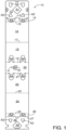
- FIG. 1 there is shown a plan view of a blank 10 capable of forming a carton or carrier 90, as shown in Figure 4 , for carrying a group of primary products such as, but not limited to, bottles, hereinafter referred to as articles B.
- the blank 10 forms a secondary package for packaging at least one primary product container or package.
- the terms “carton” and “carrier” refer, for the non-limiting purpose of illustrating the various features of the invention, to a container 90 for engaging and carrying articles, such as primary product containers. It is contemplated that the teachings of the invention can be applied to various product containers, which may or may not be tapered and/or cylindrical.
- Other exemplary containers include bottles (for example metallic, glass or plastics bottles), cans (for example aluminum cans), tins, pouches, packets, and the like.
- the blank 10 is formed from a sheet of suitable substrate.
- suitable substrate includes all manner of foldable sheet material such as paperboard, corrugated board, cardboard, plastic, combinations thereof, and the like. It should be recognized that one or other numbers of blanks may be employed, where suitable, for example, to provide the carrier structure described in more detail below.
- the packaging structure or carton 90 described herein may be formed from a sheet material such as paperboard, which may be made of or coated with materials to increase its strength.
- a sheet material such as paperboard
- An example of such a sheet material is tear-resistant NATRALOCK ® paperboard made by WestRock Company.
- the tear resistant materials may be provided by more than one layer, to help improve the tear-resistance of the package.
- one surface of the sheet material may have different characteristics to the other surface.
- the surface of the sheet material that faces outwardly from a finished package may be particularly smooth and may have a coating such as a clay coating or other surface treatment to provide good printability.
- the surface of the sheet material that faces inwardly may, on the other hand, be provided with a coating, a layer, a treatment or be otherwise prepared to provide properties such as one or more of tear-resistance, good glue-ability, heat sealability, or other desired functional properties.
- the blank 10 is configured to form a carton or carrier 90 for packaging an exemplary arrangement of exemplary articles B.
- the blank 10 can be configured to form a carrier 90 for packaging other types, number, and size of articles and/or for packaging articles in a different arrangement or configuration for example, but not limited to, fully enclosed cartons or wrap-around carriers, the articles may be cups, pouches, pots, or cans.
- FIG. 1 there is illustrated a blank 10 for forming a carton 90 (see Figure 4 ) according to a first embodiment.
- the blank 10 comprises a plurality of panels 12, 14, 16, 18, 20, 22, 24, 26, 28 arranged in a linear series hinged one to the next by a respective fold lines 13, 15, 17, 19, 21, 23, 25, 27.
- the plurality of main panels 12, 14, 16, 18, 20, 22, 24, 26, 28 form a wrap-around carrier 90.
- the plurality of panels 12, 14, 16, 18, 20, 22, 24, 26, 28 comprises a first base panel 12.
- a first corner or bevel panel 14 is hingedly connected to the first base panel 12 by a hinged connection in the form of a fold line 13.
- the first corner or bevel panel 14 is hingedly connected to a first lower side panel 16 by a hinged connection in the form of a fold line 15.
- the first lower side panel 16 is hingedly connected to a first upper side panel 18 by a hinged connection in the form of a fold line 17.
- the first upper side panel 18 is hingedly connected to a top panel 20 by a hinged connection in the form of a fold line 19.
- the top panel 20 is hingedly connected to a second upper side panel 22 by a hinged connection in the form of a fold line 21.
- the second upper side panel 22 is hingedly connected to a second lower side panel 24 by a hinged connection in the form of a fold line 23.
- the second lower side panel 24 is hingedly connected to a second corner or bevel panel 26 by a hinged connection in the form of a fold line 25.
- the second corner or bevel panel 26 is hingedly connected to a second base panel 28 by a hinged connection in the form of a fold line 27.
- first and second bevel panels 14, 26 may be omitted, the first and second bevel panels 14, 26 may be considered to form part of the side panel 16/18, 22/24 to which they are hingedly connected, alternatively, the first and second bevel panels 14, 26 may be considered to form part of the base panel12, 28 to which they are hingedly connected.
- the first and second upper side panels 18, 22 each comprises upper apertures A4 for receiving an upper portion of a respective article B.
- the first and second upper side panels 18, 22 each comprise two upper apertures A4.
- the upper apertures A4 may be configured such that a portion of the material which would otherwise form one of the first and second upper side panels 18, 22 is integral with the top panel 20 and forms a cover tab.
- the first and second bevel panels 14, 26 may each comprise at least one heel engagement structures.
- the first and second bevel panels 14, 26 each comprise two heel engagement structures.
- Each heel engagement structure takes the form of a heel aperture A3 struck, at least in part, from (or defined, at least in part, in) one of the first and second bevel panels 14, 26.
- the heel aperture A3 may extend into a respective one of the first and second lower side panels 16, 24.
- the heel apertures A3 may be configured such that a portion of the material which would otherwise form one of the first and second lower side panels 16, 24 is integral with the one of the first and second base panels 12, 28 and forms a base tab.
- Each of the first and second base panels 12, 28 may comprise at least one assembly or handling aperture A2.
- the handling aperture A2 may be generally triangular in shape and may be configured to be engaged by a tool of a packaging machine to facilitate assembly, for example, but not limited to, alignment and tightening, of the carton 90.
- the first base panel 12 comprises four handling apertures A2.
- the second base panel 28 comprises two handling apertures A2.
- Each handling aperture A2 in the second base panel 28 in configured to be in registry or alignment with one of the four handling apertures A2 in the first base panel 12.
- Each of the first and second base panels 12, 28 may comprise a post or pinnacle receiving opening A1, A5, best shown in Figure 2 .
- the first base panel 12 may comprise a first post receiving opening A1.
- the first post receiving opening A1 may be generally square, diamond or kite shaped.
- the second base panel 28 may comprise a second post receiving opening A5.
- the second post receiving opening A5 may be defined, at least in part, by at least one tab 40A, 40B.
- the second post receiving opening A5 is defined by two tabs 40A, 40B.
- a first tab 40A is struck from the second base panel 28 and is hingedly connected thereto by a first fold line 41A.
- a second tab 40B is struck from the second base panel 28 and is hingedly connected thereto by a second fold line 41B.
- the second tab 40B may be severably connected to the first tab 40A by a severance line 43.
- the first and second tabs 40A, 40B each define a portion of a free edge of the second base panel 28.
- the second post receiving opening A5 interrupts the free edge of the second base panel 28 when the first and second tabs 40A, 40B are displaced out of the plane of the second base panel 28.
- the blank 10 may comprise a handle structure H.
- the handle structure H takes the form of a finger opening in the top panel 20.
- the finger opening may be defined, at least in part by a handle tab 60 struck from the top panel 20 and hingedly connected thereto by a hinged connection in the form of a fold line 61.
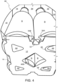
- the blank 10 is foldable to form a package 90 as illustrated in Figure 4 .
- the first and second base panels 12, 28 are engageable with one another in an overlapping relationship to form a composite base wall 12/28 of the carton 90.
- the blank 10 comprises at least one complementary locking mechanism for securing the second base panel 28 to the first base panel 12.
- the blank 10 comprises at least one first or end locking arrangement and at least one second or side locking arrangement.
- the illustrated embodiment comprises two side locking arrangement and a single end locking arrangement.
- the end locking arrangement comprises a first part M struck from, or defined in, the first base panel 12 and a second part F struck from, or defined in, the second base panel 28.
- the first part M of the end locking arrangement takes the form of a locking tab 52, also referred to herein as a male tab, struck from the first base panel 12 and hingedly connected thereto by a hinged connection in the form of a fold line 53.
- the male tab 52 may be substantially arrow-head shaped.
- the second part F of the end locking arrangement takes the form of a receiving opening, the receiving opening may be defined by a receiving tab 50, also referred to herein as a female tab, struck from the second base panel 28 and hingedly connected thereto by a hinged connection in the form of a fold line 28.
- the fold line 28 may be collinear or coincident with the fold line 27 hinging the second base panel 28 to the second bevel panel 26.
- the receiving opening may be shaped to define a waist such that, upon receipt of the male tab 52, portions of the second base panel 28, on opposed sides of the waist, prevent or inhibit removal or withdrawal of the male tab 52 therethrough.
- end edge of the male tab 52 is defined by a recess struck from, or defined in, the free end edge of the first base panel 12.
- The, or each, side locking arrangement comprises a first part ML struck from, or defined in, the first base panel 12 and a second part FR struck from, or defined in, the second base panel 28.
- the first part ML of the side locking arrangement comprises a securing tab 32, also referred to herein as male tab, struck from the first base panel 12 and hingedly connected thereto by a hinged connection in the form of a fold line 35.
- the securing tab 32 may be substantially arrow-head shaped, in the illustrated embodiment the arrow-head shape is truncated or blunted at a leading or outer end.
- the securing tab 32 may comprises a pair of divergently arranged fold lines 35A, 35B, the pair of divergently arranged fold lines 35A, 35B configured to intersect or meet at the truncated or blunted end of the securing tab 32; in this way the securing tab 32 comprises a pair of wing members 34A, 34B hinged to a central portion of the securing tab 32.
- the first part ML of the side locking arrangement comprises at least one displaceable tab-protecting member 30A, 30B.
- the illustrated embodiment comprises two displaceable tab-protecting members 30A, 30B each taking the form of a displaceable flap 30A, 30B struck from the first base panel 12 and hingedly connected thereto by a respective hinged connection in the form of fold lines 31A, 31B.
- the pair of displaceable flaps 30A, 30B are separated, or separable, from each other by a cutline or severance line 33.
- the cutline or severance line 33 may extend from the truncated or blunted end of the securing tab 32 to a free side edge of the first base panel 12.
- the fold lines 31A, 31B may be obliquely oriented with respect to a free side edge of the first base panel 12.
- the fold lines 31A, 31B may be divergently arranged with respect to each other.
- the second part FR of the side locking arrangement takes the form of a second receiving opening.
- the second receiving opening may be defined by a recess struck from a side edge of the second base panel 28.
- the second receiving opening may be shaped to define a waist W such that, upon receipt of the securing tab 32, portions of the second base panel 28, on opposed sides of the waist W, prevent or inhibit removal or withdrawal of the securing tab 32 therethrough.
- the blank 10 is foldable to form a package 90 as illustrated in Figure 4 .
- the article carrier 90 can be formed by a series of sequential folding operations.
- the folding process is not limited to that described below and may be altered according to particular manufacturing requirements.
- the blank 10 is lowered with respect to a group of articles B.
- An article B, or part thereof, is received in each of the upper apertures A4.
- the first lower side panel 16, along with the first bevel panel 14 and first base panel 12, is folded with respect to the first upper side panel 18, about fold line 17.
- the second lower side panel 24, along with the second bevel panel 26 and second base panel 28, is folded with respect to the second upper side panel 22, about fold line 23.
- the second bevel panel 26, along with the second base panel 28, is folded with respect to the second lower side panel 24, about fold line 25.
- the second base panel 28 is folded with respect to the second bevel panel 26, about fold line 27 to bring the second base panel 28 into face-to-face relationship with the bases of the articles B.
- the first bevel panel 14, along with the first base panel 12, is folded with respect to the first lower side panel 16, about fold line 15.
- the first base panel 12 is folded with respect to the first bevel panel 14, about fold line 13 to bring the first base panel 12 into face-to-face relationship with the second base panel 28, as shown in Figure 3 .
- Each first part ML of the side locking arrangement is brought into alignment, or vertical registry, with a respective second part FR of the side locking arrangement.
- the first part M of the end locking arrangement is brought into alignment, or vertical registry, with the second part F of the end locking arrangement.
- the male tab 52 is pressed inwardly, in doing so the female tab 50 is displaced inwardly creating a receiving opening, the male tab 52 pass through the second base panel 28 and is received in the receiving opening.
- the locking tabs 32 are pressed inwardly passing through the second base panel 28 and are received in the second receiving openings FR, as shown in Figure 5 .
- the side locking arrangements may be engaged or activated as or when the carton 90 is loaded into a crate C or other suitable apparatus, the crate C comprising a post or pinnacle P for stabilizing the articles B, as shown in Figure 6 .
- the locking tabs 32 may be engaged with the second receiving openings FR prior to loading the carton 90 into a crate C.
- the displaceable flaps 30A, 30B may be displaced inwardly of the carton 90 as or when the carton 90 is loaded into a crate C.
- the present disclosure provides a carton blank 10 for forming an article carrier 90.
- the carton blank 10 comprises a panel interlocking device which having at least one locking tab 32 and at least one displaceable tab-protecting member 30A, 30B.
- the at least one displaceable tab-protecting member 30A, 30B is disposed next to the at least one locking tab 32.
- the at least one tab-protecting member 30A, 30B comprises a free edge S e which defines part of the outline O L of the blank 10.
- the carton blank 10 comprises a plurality of panels for forming a tubular structure.
- the plurality of panels including a pair of panels 12, 28 configured to be disposed in overlapping relationship in a setup article carrier 90.
- the at least one locking tab 32 and the at least one displaceable tab-protecting member 30A, 30B are defined in one of said pair of panels 12, 28.
- the displaceable tab-protecting members 30A, 30B protect the locking tab 32 while the blank 10 is handled or transferred on a packaging machine. Driving or pushing lugs, or other suitable tools, of the packaging machine may be brought into contact with the displaceable tab-protecting members 30A, 30B during handling, thus reducing the likelihood of the locking tab 32 being deformed or damaged by one of the machine tools.
- Providing the displaceable tab-protecting members 30A, 30B may be further beneficial during manufacturing or cutting of the blanks 10.
- Providing the displaceable tab-protecting members 30A, 30B has the effect of eliminating, at least some, waste, or scraps of substrate material, paperboard, or cardboard. Dispensing with the requirement to eject or remove of scraps of substrate material from about, or around, the locking tabs 32 reduces the chance of damage thereto.
- the present disclosure also provides a panel interlocking device comprising at least one locking tab 32 formed from a primary panel 12 having a first free edge O L and at least one displaceable tab-protecting member 30A, 30B disposed next to the at least one locking tab 32.
- the at least one tab-protecting member 30A, 30B comprises a second free edge S e , the first free edge O L comprising the second free edge S e .
- the first free edge O L is contiguous or continuous with the second free edge S e .
- the displaceable tab-protecting members 30A, 30B may be beneficial because they keep the respective primary panel 12 from which they are formed rigid.
- the present disclosure further provides a carton blank 10 comprising a scrap-free panel interlocking device which comprises at least one locking tab 32 and at least one displaceable space-filling member 30A, 30B defined partially by a severance line 37.
- the severance line 37 also defines part of the at least one locking tab 32.
- the at least one space-filling member 30A, 30B comprises a free edge S e which defines part of the outline O L of the blank 10.
- the present disclosure also provides a panel interlocking device comprising at least one locking tab 32 formed from a primary panel 12 having a first free edge O L .
- the at least one locking tab 32 is movable between an inactive position and an activated position.
- the panel interlocking device comprises at least one displaceable space-filling member 30A, 30B defined partially by a severance line 37.
- the severance line 37 also defines part of the at least one locking tab 32 when the at least one locking tab 32 is in the inactive position.
- the at least one space-filling member 30A, 30B comprises a second free edge S e , the first free edge O L comprising the second free edge S e .
- the present disclosure also provides a carton blank 10 comprising a cut-out A5 which opens to the outline O L of the blank 10 and at least one displaceable gate member 40A, 40B connected to the blank 10 and extending into the cut-out A5.
- the at least one gate member 40A, 40B comprises a free edge E e which defines part of the outline O L of the blank 10.
- hinged connection and “fold line” refer to all manner of lines that define hinge features of the blank, facilitate folding portions of the blank with respect to one another, or otherwise indicate optimal panel folding locations for the blank. Any reference to “hinged connection” should not be construed as necessarily referring to a single fold line only; indeed, a hinged connection can be formed from two or more fold lines wherein each of the two or more fold lines may be either straight/linear or curved/curvilinear in shape. When linear fold lines form a hinged connection, they may be disposed parallel with each other or be slightly angled with respect to each other.
- curvilinear fold lines When curvilinear fold lines form a hinged connection, they may intersect each other to define a shaped panel within the area surrounded by the curvilinear fold lines.
- a typical example of such a hinged connection may comprise a pair of arched or arcuate fold lines intersecting at two points such that they define an elliptical panel therebetween.
- a hinged connection may be formed from one or more linear fold lines and one or more curvilinear fold lines.
- a typical example of such a hinged connection may comprise a combination of a linear fold line and an arched or arcuate fold line which intersect at two points such that they define a half moon-shaped panel therebetween.
- fold line may refer to one of the following: a scored line, an embossed line, a debossed line, a line of perforations, a line of short slits, a line of half-cuts, a single half-cut, an interrupted cutline, a line of aligned slits, a line of scores and any combination of the aforesaid options.
- hinged connections and fold lines can each include elements that are formed in the substrate of the blank including perforations, a line of perforations, a line of short slits, a line of half-cuts, a single half-cut, a cutline, an interrupted cutline, slits, scores, any combination thereof, and the like.
- the elements can be dimensioned and arranged to provide the desired functionality.
- a line of perforations can be dimensioned or designed with degrees of weakness to define a fold line or a severance line or both.
- the line of perforations can be designed to facilitate folding and resist breaking, to facilitate folding and facilitate breaking with more effort, or to facilitate breaking with little effort.
- in registry with refers to the alignment of two or more elements in an erected carton, such as an aperture formed in a first of two overlapping panels and a second aperture formed in a second of two overlapping panels. Those elements in registry with each other may be aligned with each other in the direction of the thickness of the overlapping panels. For example, when an aperture in a first panel is "in registry with" a second aperture in a second panel that is placed in an overlapping arrangement with the first panel, an edge of the aperture may extend along at least a portion of an edge of the second aperture and may be aligned, in the direction of the thickness of the first and second panels, with the second aperture.
Landscapes
- Engineering & Computer Science (AREA)
- Mechanical Engineering (AREA)
- Cartons (AREA)
Abstract
Aspects of the disclosure relate to a panel interlocking device, an article carrier (90) for packaging a plurality of articles (B), and to a blank (10) for forming the panel interlocking device or article carrier (90). The panel interlocking device comprising at least one locking tab (32) and at least one displaceable tab-protecting member (30A, 30B) disposed next to the at least one locking tab (32). The at least one tab-protecting member (30A, 30B) comprises a free edge (S<sub>e</sub>) which defines part of the outline (O<sub>L</sub>) of the blank (10).
Description
- The present invention relates to article carriers, to blanks for forming the same, and to panel interlocking devices. More specifically, but not exclusively, the invention relates to a carrier of the wraparound style for use with a crate or other tertiary transport device.
- In the field of packaging, it is known to provide article carriers or cartons for carrying multiple articles. Cartons are well known in the art and are useful for enabling consumers to transport, store and access a group of articles for consumption. For cost and environmental considerations, such cartons or carriers need to be formed from as little material as possible and cause as little wastage in the materials from which they are formed as possible. Further considerations are the strength of the carton and its suitability for holding and transporting large weights of articles. It is desirable that the contents of the carton are secure within the carton.
- It is an object of the present invention to provide a carrier adapted to be employed in a crate or similar device having a post or pinnacle provided therein.
- The present invention seeks to provide an improvement in the field of cartons, typically formed from paperboard or the like.
- An aspect of the invention provides a blank for forming an article carrier. The blank comprises a panel interlocking device. The panel interlocking device comprises at least one locking tab and at least one displaceable tab-protecting member. The at least one displaceable tab-protecting member is disposed next to the at least one locking tab. The at least one tab-protecting member comprises a free edge which defines part of the outline of the blank.
- Optionally, the blank comprises a first panel and the at least one locking tab and at least one displaceable tab-protecting member are defined in the first panel.
- Optionally, the blank comprises a second panel, the second panel comprises at least one receiver in the form of a cutaway for receiving the at least one locking tab.
- Optionally, the at least one displaceable tab-protecting member is configured to be disposed in at least partial overlapping relationship with a portion of the second panel adjacent the at least one receiver in a setup article carrier.
- Optionally, the blank comprises a plurality of panels for forming a tubular structure, the plurality of panels including a pair of panels configured to be disposed in overlapping relationship in a setup article carrier, wherein the at least one locking tab and the at least one displaceable tab-protecting member are defined in one of said pair of panels.
- An aspect of the invention provides a panel interlocking device comprising at least one locking tab formed from a primary panel having a first free edge and at least one displaceable tab-protecting member disposed next to the at least one locking tab. The at least one tab-protecting member comprises a second free edge. The first free edge comprises the second free edge.
- Optionally, the first free edge is continuous with the second free edge.
- Optionally, the first free edge is contiguous with the second free edge.
- Another aspect of the invention provides an article carrier comprising the aforementioned panel interlocking device.
- Optionally, the article carrier comprises a first panel and the at least one locking tab and at least one displaceable tab-protecting member are defined in the first panel.
- Optionally, the article carrier comprises a second panel, the second panel comprises at least one receiver in the form of a cutaway for receiving the at least one locking tab.
- Optionally, the at least one displaceable tab-protecting member and the portion of the second panel adjacent the at least one receiver are displaced inwardly by a pinnacle or post of tertiary packaging apparatus when the article carrier is received therein.
- Yet another aspect of the invention provides a blank for forming an article carrier. The blank comprises a scrap-free panel interlocking device including at least one locking tab and at least one displaceable space-filling member. The at least one displaceable space-filling member is defined partially by a severance line. The severance line also defines part of the at least one locking tab. The at least one space-filling member comprises a free edge which defines part of the outline of the blank.
- A further aspect of the invention provides a panel interlocking device comprising at least one locking tab formed from a primary panel having a first free edge. The at least one locking tab is movable between an inactive position and an activated position. The panel interlocking device comprises at least one displaceable space-filling member defined partially by a severance line. The severance line also defines part of the at least one locking tab when the at least one locking tab is in the inactive position. The at least one space-filling member comprises a second free edge. The first free edge comprises the second free edge.
- An aspect of the invention provides a blank for forming an article carrier. The blank comprises a panel having a cut-out which opens to the outline of the blank, that is to say, interrupts or defines the perimeter of the blank, and at least one displaceable gate member connected to said panel of the blank and extending into the cut-out. The at least one gate member comprises a free edge which defines part of the outline of the blank. The at least one gate member when displaced out of the plane of the panel may be considered to create an opening or entrance in the outline of the blank in communication with the cut-out.
- Further features and advantages of the present invention will be apparent from the specific embodiments illustrated in the drawings and discussed below.
- Within the scope of this application, it is envisaged or intended that the various aspects, embodiments, examples, features and alternatives set out in the preceding paragraphs, in the claims and/or in the following description and drawings may be considered or taken independently or in any combination thereof.
- Features or elements described in connection with, or relation to, one embodiment are applicable to all embodiments unless there is an incompatibility of features. One or more features or elements from one embodiment may be incorporated into, or combined with, any of the other embodiments disclosed herein, said features or elements extracted from said one embodiment may be included in addition to, or in replacement of one or more features or elements of said other embodiment.
- A feature, or combination of features, of an embodiment disclosed herein may be extracted in isolation from other features of that embodiment. Alternatively, a feature, or combination of features, of an embodiment may be omitted from that embodiment.
- Embodiments of the invention will now be described with reference to the accompanying drawings, in which:
-
Figure 1 is a plan view from above of a blank for forming a carrier according to an embodiment of the disclosure; -
Figure 2 is an enlarged plan view from above of portion of the blank ofFigure 1 -
Figure 3 is a plan view from above of lap panels of the blank ofFigure 1 disposed in overlapping relationship; -
Figure 4 is a perspective view of a carton formed from the blank ofFigure 1 -
Figure 5 is a perspective view of a portion of the carton formed from the blank ofFigure 1 ; and -
Figure 6 is a perspective view of the carton ofFigure 4 being received in a crate or tertiary packaging apparatus. - Detailed descriptions of specific embodiments of the package, blanks and cartons are disclosed herein. It will be understood that the disclosed embodiments are merely examples of the way in which certain aspects of the invention can be implemented and do not represent an exhaustive list of all of the ways the invention may be embodied. As used herein, the word "exemplary" is used expansively to refer to embodiments that serve as illustrations, specimens, models, or patterns. Indeed, it will be understood that the packages, blanks, and cartons described herein may be embodied in various and alternative forms. The Figures are not necessarily to scale and some features may be exaggerated or minimized to show details of particular components. Well-known components, materials or methods are not necessarily described in great detail in order to avoid obscuring the present disclosure. Any specific structural and functional details disclosed herein are not to be interpreted as limiting, but merely as a basis for the claims and as a representative basis for teaching one skilled in the art to variously employ the invention.
- Referring to
Figure 1 , there is shown a plan view of a blank 10 capable of forming a carton orcarrier 90, as shown inFigure 4 , for carrying a group of primary products such as, but not limited to, bottles, hereinafter referred to as articles B. The blank 10 forms a secondary package for packaging at least one primary product container or package. - In the embodiments detailed herein, the terms "carton" and "carrier" refer, for the non-limiting purpose of illustrating the various features of the invention, to a
container 90 for engaging and carrying articles, such as primary product containers. It is contemplated that the teachings of the invention can be applied to various product containers, which may or may not be tapered and/or cylindrical. Other exemplary containers include bottles (for example metallic, glass or plastics bottles), cans (for example aluminum cans), tins, pouches, packets, and the like. - The blank 10 is formed from a sheet of suitable substrate. It is to be understood that, as used herein, the term "suitable substrate" includes all manner of foldable sheet material such as paperboard, corrugated board, cardboard, plastic, combinations thereof, and the like. It should be recognized that one or other numbers of blanks may be employed, where suitable, for example, to provide the carrier structure described in more detail below.
- The packaging structure or
carton 90 described herein may be formed from a sheet material such as paperboard, which may be made of or coated with materials to increase its strength. An example of such a sheet material is tear-resistant NATRALOCK® paperboard made by WestRock Company. It should be noted that the tear resistant materials may be provided by more than one layer, to help improve the tear-resistance of the package. Typically, one surface of the sheet material may have different characteristics to the other surface. For example, the surface of the sheet material that faces outwardly from a finished package may be particularly smooth and may have a coating such as a clay coating or other surface treatment to provide good printability. The surface of the sheet material that faces inwardly may, on the other hand, be provided with a coating, a layer, a treatment or be otherwise prepared to provide properties such as one or more of tear-resistance, good glue-ability, heat sealability, or other desired functional properties. - In the illustrated embodiment, the blank 10 is configured to form a carton or
carrier 90 for packaging an exemplary arrangement of exemplary articles B. In the illustrated embodiment the arrangement is an m × n matrix or array, having two row (m=2) and two columns (n=2) two row of two articles B is provided, and the articles B may be 0.33L bottles. Alternatively, the blank 10 can be configured to form acarrier 90 for packaging other types, number, and size of articles and/or for packaging articles in a different arrangement or configuration for example, but not limited to, fully enclosed cartons or wrap-around carriers, the articles may be cups, pouches, pots, or cans. - Turning to
Figure 1 , there is illustrated a blank 10 for forming a carton 90 (seeFigure 4 ) according to a first embodiment. The blank 10 comprises a plurality ofpanels respective fold lines - The plurality of
main panels carrier 90. The plurality ofpanels first base panel 12. A first corner orbevel panel 14 is hingedly connected to thefirst base panel 12 by a hinged connection in the form of afold line 13. The first corner orbevel panel 14 is hingedly connected to a firstlower side panel 16 by a hinged connection in the form of afold line 15. The firstlower side panel 16 is hingedly connected to a firstupper side panel 18 by a hinged connection in the form of afold line 17. The firstupper side panel 18 is hingedly connected to atop panel 20 by a hinged connection in the form of afold line 19. Thetop panel 20 is hingedly connected to a secondupper side panel 22 by a hinged connection in the form of a fold line 21. The secondupper side panel 22 is hingedly connected to a secondlower side panel 24 by a hinged connection in the form of afold line 23. The secondlower side panel 24 is hingedly connected to a second corner orbevel panel 26 by a hinged connection in the form of afold line 25. The second corner orbevel panel 26 is hingedly connected to asecond base panel 28 by a hinged connection in the form of afold line 27. - In some embodiments, the first and
second bevel panels 14, 26 (also referred to herein as heel panels) may be omitted, the first andsecond bevel panels side panel 16/18, 22/24 to which they are hingedly connected, alternatively, the first andsecond bevel panels - The first and second
upper side panels upper side panels upper side panels top panel 20 and forms a cover tab. - The first and
second bevel panels second bevel panels second bevel panels lower side panels - The heel apertures A3 may be configured such that a portion of the material which would otherwise form one of the first and second
lower side panels second base panels - Each of the first and
second base panels carton 90. - In the illustrated embodiment, the
first base panel 12 comprises four handling apertures A2. Thesecond base panel 28 comprises two handling apertures A2. Each handling aperture A2 in thesecond base panel 28 in configured to be in registry or alignment with one of the four handling apertures A2 in thefirst base panel 12. - Each of the first and
second base panels Figure 2 . Thefirst base panel 12 may comprise a first post receiving opening A1. The first post receiving opening A1 may be generally square, diamond or kite shaped. - The
second base panel 28 may comprise a second post receiving opening A5. The second post receiving opening A5 may be defined, at least in part, by at least onetab tabs first tab 40A is struck from thesecond base panel 28 and is hingedly connected thereto by afirst fold line 41A. Asecond tab 40B is struck from thesecond base panel 28 and is hingedly connected thereto by a second fold line 41B. Thesecond tab 40B may be severably connected to thefirst tab 40A by aseverance line 43. - The first and
second tabs second base panel 28. The second post receiving opening A5 interrupts the free edge of thesecond base panel 28 when the first andsecond tabs second base panel 28. - The blank 10 may comprise a handle structure H. The handle structure H takes the form of a finger opening in the
top panel 20. The finger opening may be defined, at least in part by ahandle tab 60 struck from thetop panel 20 and hingedly connected thereto by a hinged connection in the form of afold line 61. - The blank 10 is foldable to form a
package 90 as illustrated inFigure 4 . The first andsecond base panels composite base wall 12/28 of thecarton 90. The blank 10 comprises at least one complementary locking mechanism for securing thesecond base panel 28 to thefirst base panel 12. - In the illustrated embodiment, the blank 10 comprises at least one first or end locking arrangement and at least one second or side locking arrangement. The illustrated embodiment comprises two side locking arrangement and a single end locking arrangement.
- The end locking arrangement comprises a first part M struck from, or defined in, the
first base panel 12 and a second part F struck from, or defined in, thesecond base panel 28. The first part M of the end locking arrangement takes the form of alocking tab 52, also referred to herein as a male tab, struck from thefirst base panel 12 and hingedly connected thereto by a hinged connection in the form of afold line 53. Themale tab 52 may be substantially arrow-head shaped. The second part F of the end locking arrangement takes the form of a receiving opening, the receiving opening may be defined by a receivingtab 50, also referred to herein as a female tab, struck from thesecond base panel 28 and hingedly connected thereto by a hinged connection in the form of afold line 28. Thefold line 28 may arranged to be collinear or coincident with thefold line 27 hinging thesecond base panel 28 to thesecond bevel panel 26. The receiving opening may be shaped to define a waist such that, upon receipt of themale tab 52, portions of thesecond base panel 28, on opposed sides of the waist, prevent or inhibit removal or withdrawal of themale tab 52 therethrough. - In the illustrated embodiment, and end edge of the
male tab 52 is defined by a recess struck from, or defined in, the free end edge of thefirst base panel 12. - The, or each, side locking arrangement comprises a first part ML struck from, or defined in, the
first base panel 12 and a second part FR struck from, or defined in, thesecond base panel 28. The first part ML of the side locking arrangement comprises a securingtab 32, also referred to herein as male tab, struck from thefirst base panel 12 and hingedly connected thereto by a hinged connection in the form of afold line 35. The securingtab 32 may be substantially arrow-head shaped, in the illustrated embodiment the arrow-head shape is truncated or blunted at a leading or outer end. The securingtab 32 may comprises a pair of divergently arrangedfold lines fold lines tab 32; in this way the securingtab 32 comprises a pair ofwing members tab 32. The first part ML of the side locking arrangement comprises at least one displaceable tab-protectingmember members displaceable flap first base panel 12 and hingedly connected thereto by a respective hinged connection in the form offold lines - The pair of
displaceable flaps severance line 33. The cutline orseverance line 33 may extend from the truncated or blunted end of the securingtab 32 to a free side edge of thefirst base panel 12. - The fold lines 31A, 31B may be obliquely oriented with respect to a free side edge of the
first base panel 12. The fold lines 31A, 31B may be divergently arranged with respect to each other. - The second part FR of the side locking arrangement takes the form of a second receiving opening. The second receiving opening may be defined by a recess struck from a side edge of the
second base panel 28. The second receiving opening may be shaped to define a waist W such that, upon receipt of the securingtab 32, portions of thesecond base panel 28, on opposed sides of the waist W, prevent or inhibit removal or withdrawal of the securingtab 32 therethrough. - The blank 10 is foldable to form a
package 90 as illustrated inFigure 4 . - Turning to the construction of the
article carrier 90 as illustrated inFigure 4 , thearticle carrier 90 can be formed by a series of sequential folding operations. The folding process is not limited to that described below and may be altered according to particular manufacturing requirements. - The blank 10 is lowered with respect to a group of articles B. An article B, or part thereof, is received in each of the upper apertures A4.
- The first
upper side panel 18, along with the firstlower side panel 16,first bevel panel 14 andfirst base panel 12, is folded with respect to thetop panel 20, aboutfold line 19. The secondupper side panel 22, along with the secondlower side panel 24,second bevel panel 26 andsecond base panel 28, is folded with respect to thetop panel 20, about fold line 21. - The first
lower side panel 16, along with thefirst bevel panel 14 andfirst base panel 12, is folded with respect to the firstupper side panel 18, aboutfold line 17. The secondlower side panel 24, along with thesecond bevel panel 26 andsecond base panel 28, is folded with respect to the secondupper side panel 22, aboutfold line 23. - The
second bevel panel 26, along with thesecond base panel 28, is folded with respect to the secondlower side panel 24, aboutfold line 25. Thesecond base panel 28 is folded with respect to thesecond bevel panel 26, aboutfold line 27 to bring thesecond base panel 28 into face-to-face relationship with the bases of the articles B. - The
first bevel panel 14, along with thefirst base panel 12, is folded with respect to the firstlower side panel 16, aboutfold line 15. Thefirst base panel 12 is folded with respect to thefirst bevel panel 14, aboutfold line 13 to bring thefirst base panel 12 into face-to-face relationship with thesecond base panel 28, as shown inFigure 3 . - Each first part ML of the side locking arrangement is brought into alignment, or vertical registry, with a respective second part FR of the side locking arrangement. The first part M of the end locking arrangement is brought into alignment, or vertical registry, with the second part F of the end locking arrangement.
- The
male tab 52 is pressed inwardly, in doing so thefemale tab 50 is displaced inwardly creating a receiving opening, themale tab 52 pass through thesecond base panel 28 and is received in the receiving opening. - The locking
tabs 32 are pressed inwardly passing through thesecond base panel 28 and are received in the second receiving openings FR, as shown inFigure 5 . - In some embodiments, the side locking arrangements may be engaged or activated as or when the
carton 90 is loaded into a crate C or other suitable apparatus, the crate C comprising a post or pinnacle P for stabilizing the articles B, as shown inFigure 6 . - In other embodiments, the locking
tabs 32 may be engaged with the second receiving openings FR prior to loading thecarton 90 into a crate C. The displaceable flaps 30A, 30B may be displaced inwardly of thecarton 90 as or when thecarton 90 is loaded into a crate C. - The present disclosure provides a carton blank 10 for forming an
article carrier 90. The carton blank 10 comprises a panel interlocking device which having at least onelocking tab 32 and at least one displaceable tab-protectingmember member locking tab 32. The at least one tab-protectingmember - The carton blank 10 comprises a plurality of panels for forming a tubular structure. The plurality of panels including a pair of
panels setup article carrier 90. The at least onelocking tab 32 and the at least one displaceable tab-protectingmember panels - The displaceable tab-protecting
members locking tab 32 while the blank 10 is handled or transferred on a packaging machine. Driving or pushing lugs, or other suitable tools, of the packaging machine may be brought into contact with the displaceable tab-protectingmembers locking tab 32 being deformed or damaged by one of the machine tools. - Providing the displaceable tab-protecting
members blanks 10. Providing the displaceable tab-protectingmembers tabs 32 reduces the chance of damage thereto. - The present disclosure also provides a panel interlocking device comprising at least one
locking tab 32 formed from aprimary panel 12 having a first free edge OL and at least one displaceable tab-protectingmember locking tab 32. The at least one tab-protectingmember - The displaceable tab-protecting
members primary panel 12 from which they are formed rigid. - The present disclosure further provides a carton blank 10 comprising a scrap-free panel interlocking device which comprises at least one
locking tab 32 and at least one displaceable space-fillingmember severance line 37. Theseverance line 37 also defines part of the at least onelocking tab 32. The at least one space-fillingmember - The present disclosure also provides a panel interlocking device comprising at least one
locking tab 32 formed from aprimary panel 12 having a first free edge OL. The at least onelocking tab 32 is movable between an inactive position and an activated position. The panel interlocking device comprises at least one displaceable space-fillingmember severance line 37. Theseverance line 37 also defines part of the at least onelocking tab 32 when the at least onelocking tab 32 is in the inactive position. The at least one space-fillingmember - The present disclosure also provides a carton blank 10 comprising a cut-out A5 which opens to the outline OL of the blank 10 and at least one
displaceable gate member gate member - It can be appreciated that various changes may be made within the scope of the present invention. For example, the size and shape of the panels and apertures may be adjusted to accommodate articles of differing size or shape.
- It will be recognized that as used herein, directional references such as "top", "bottom", "base", "front", "back", "end", "side", "inner", "outer", "upper" and "lower" do not necessarily limit the respective panels to such orientation but may merely serve to distinguish these panels from one another.
- As used herein, the terms "hinged connection" and "fold line" refer to all manner of lines that define hinge features of the blank, facilitate folding portions of the blank with respect to one another, or otherwise indicate optimal panel folding locations for the blank. Any reference to "hinged connection" should not be construed as necessarily referring to a single fold line only; indeed, a hinged connection can be formed from two or more fold lines wherein each of the two or more fold lines may be either straight/linear or curved/curvilinear in shape. When linear fold lines form a hinged connection, they may be disposed parallel with each other or be slightly angled with respect to each other. When curvilinear fold lines form a hinged connection, they may intersect each other to define a shaped panel within the area surrounded by the curvilinear fold lines. A typical example of such a hinged connection may comprise a pair of arched or arcuate fold lines intersecting at two points such that they define an elliptical panel therebetween. A hinged connection may be formed from one or more linear fold lines and one or more curvilinear fold lines. A typical example of such a hinged connection may comprise a combination of a linear fold line and an arched or arcuate fold line which intersect at two points such that they define a half moon-shaped panel therebetween.
- As used herein, the term "fold line" may refer to one of the following: a scored line, an embossed line, a debossed line, a line of perforations, a line of short slits, a line of half-cuts, a single half-cut, an interrupted cutline, a line of aligned slits, a line of scores and any combination of the aforesaid options.
- It should be understood that hinged connections and fold lines can each include elements that are formed in the substrate of the blank including perforations, a line of perforations, a line of short slits, a line of half-cuts, a single half-cut, a cutline, an interrupted cutline, slits, scores, any combination thereof, and the like. The elements can be dimensioned and arranged to provide the desired functionality. For example, a line of perforations can be dimensioned or designed with degrees of weakness to define a fold line or a severance line or both. The line of perforations can be designed to facilitate folding and resist breaking, to facilitate folding and facilitate breaking with more effort, or to facilitate breaking with little effort.
- The phrase "in registry with" as used herein refers to the alignment of two or more elements in an erected carton, such as an aperture formed in a first of two overlapping panels and a second aperture formed in a second of two overlapping panels. Those elements in registry with each other may be aligned with each other in the direction of the thickness of the overlapping panels. For example, when an aperture in a first panel is "in registry with" a second aperture in a second panel that is placed in an overlapping arrangement with the first panel, an edge of the aperture may extend along at least a portion of an edge of the second aperture and may be aligned, in the direction of the thickness of the first and second panels, with the second aperture.
Claims (15)
- A blank for forming an article carrier, the blank comprising a panel interlocking device, the panel interlocking device comprising at least one locking tab and at least one displaceable tab-protecting member, the at least one displaceable tab-protecting member being disposed next to the at least one locking tab, wherein the at least one tab-protecting member comprises a free edge which defines part of the outline of the blank.
- A blank according to claim 1, wherein the blank comprises a first panel, and wherein the at least one locking tab and at least one displaceable tab-protecting member are defined in the first panel.
- A blank according to claim 1, wherein the blank comprises a second panel, the second panel comprises at least one receiver in the form of a cutaway for receiving the at least one locking tab.
- A blank according to claim 3, wherein the at least one displaceable tab-protecting member is configured to be disposed in at least partial overlapping relationship with a portion of the second panel adjacent the at least one receiver in a setup article carrier.
- A blank according to claim 1, wherein the blank comprises a plurality of panels for forming a tubular structure, the plurality of panels including a pair of panels configured to be disposed in overlapping relationship in a setup article carrier, wherein the at least one locking tab and the at least one displaceable tab-protecting member are defined in one of said pair of panels.
- A panel interlocking device comprising at least one locking tab formed from a primary panel having a first free edge and at least one displaceable tab-protecting member disposed next to the at least one locking tab, the at least one tab-protecting member comprising a second free edge, wherein the first free edge comprises the second free edge.
- A panel interlocking device according to claim 6, wherein the first free edge is continuous with the second free edge.
- A panel interlocking device according to claim 6, wherein the first free edge is contiguous with the second free edge.
- An article carrier comprising the panel interlocking device according to claim 6.
- An article carrier according to claim 9, wherein the article carrier comprises a first panel, and wherein the at least one locking tab and at least one displaceable tab-protecting member are defined in the first panel.
- An article carrier according to claim 9, wherein the article carrier comprises a second panel, the second panel comprises at least one receiver in the form of a cutaway for receiving the at least one locking tab.
- An article carrier according to claim 11, wherein the at least one displaceable tab-protecting member and a portion of the second panel adjacent the at least one receiver are displaced inwardly by pinnacles of tertiary packaging apparatus when the article carrier is received therein.
- A blank for forming an article carrier comprising, the blank comprising a scrap-free panel interlocking device including at least one locking tab and at least one displaceable space-filling member, the at least one displaceable space-filling member being defined partially by a severance line which also defines part of the at least one locking tab, wherein the at least one space-filling member comprises a free edge which defines part of an outline of the blank.
- A panel interlocking device comprising at least one locking tab formed from a primary panel having a first free edge, the at least one locking tab being movable between an inactive position and an activated position, the panel interlocking device comprising at least one displaceable space-filling member defined partially by a severance line which also defines part of the at least one locking tab when the at least one locking tab is in the inactive position, wherein the at least one space-filling member comprises a second free edge, the first free edge comprising the second free edge.
- A blank for forming an article carrier, the blank comprising a cut-out which opens to an outline of the blank and at least one displaceable gate member connected to the blank and extending into the cut-out, wherein the at least one gate member comprises a free edge which defines part of the outline of the blank.
Applications Claiming Priority (1)
| Application Number | Priority Date | Filing Date | Title |
|---|---|---|---|
| US202363447679P | 2023-02-23 | 2023-02-23 |
Publications (1)
| Publication Number | Publication Date |
|---|---|
| EP4458721A1 true EP4458721A1 (en) | 2024-11-06 |
Family
ID=89940803
Family Applications (1)
| Application Number | Title | Priority Date | Filing Date |
|---|---|---|---|
| EP24157523.2A Pending EP4458721A1 (en) | 2023-02-23 | 2024-02-14 | Article carrier and blank therefor |
Country Status (1)
| Country | Link |
|---|---|
| EP (1) | EP4458721A1 (en) |
Citations (4)
| Publication number | Priority date | Publication date | Assignee | Title |
|---|---|---|---|---|
| FR1504754A (en) * | 1966-10-25 | 1967-12-08 | Lincrusta | Packaging for display |
| FR2717451A1 (en) * | 1994-03-15 | 1995-09-22 | Ap Emballages France | Case for group of nested articles such as bottles |
| EP0842098A1 (en) * | 1995-07-29 | 1998-05-20 | Riverwood International Corporation | Article retaining sleeve |
| DE202005000949U1 (en) * | 2005-01-20 | 2005-03-24 | Mayr Melnhof Karton Ag Wien | Packaging for transporting and storing cans or bottles, has side walls connected to base along non straight lines |
-
2024
- 2024-02-14 EP EP24157523.2A patent/EP4458721A1/en active Pending
Patent Citations (4)
| Publication number | Priority date | Publication date | Assignee | Title |
|---|---|---|---|---|
| FR1504754A (en) * | 1966-10-25 | 1967-12-08 | Lincrusta | Packaging for display |
| FR2717451A1 (en) * | 1994-03-15 | 1995-09-22 | Ap Emballages France | Case for group of nested articles such as bottles |
| EP0842098A1 (en) * | 1995-07-29 | 1998-05-20 | Riverwood International Corporation | Article retaining sleeve |
| DE202005000949U1 (en) * | 2005-01-20 | 2005-03-24 | Mayr Melnhof Karton Ag Wien | Packaging for transporting and storing cans or bottles, has side walls connected to base along non straight lines |
Similar Documents
| Publication | Publication Date | Title |
|---|---|---|
| US10569947B2 (en) | Carton and carton blank and a handle structure therefor | |
| US10850902B2 (en) | Carton and blank therefor | |
| US10710767B2 (en) | Carton and blank therefor | |
| EP3710376B1 (en) | Carton and blank therefor | |
| US11220385B2 (en) | Carton and blank therefor | |
| WO2019139763A1 (en) | Carton and blank therefor | |
| US20210198021A1 (en) | Carton and blank therefor | |
| WO2018148627A1 (en) | Carton and blank therefor | |
| US11993439B2 (en) | Carton and blank therefor | |
| US20220297911A1 (en) | Article carrier and blank therfor | |
| AU2020359410A1 (en) | Article carrier, blank and method of constructing the same | |
| EP4458721A1 (en) | Article carrier and blank therefor | |
| WO2016054466A1 (en) | Carton and carton blank | |
| US20220250820A1 (en) | Carton and blank therefor | |
| US20240294315A1 (en) | Article carrier and blank therefor | |
| EP4045426B1 (en) | Carton and blank therefor | |
| US20220258941A1 (en) | Carton and blank therefor | |
| WO2025245522A1 (en) | Article carrier and blank therefor | |
| US20220112016A1 (en) | Carton and blank therefor | |
| WO2022251470A1 (en) | Handle structure, article carrier and blank therefor |
Legal Events
| Date | Code | Title | Description |
|---|---|---|---|
| PUAI | Public reference made under article 153(3) epc to a published international application that has entered the european phase |
Free format text: ORIGINAL CODE: 0009012 |
|
| STAA | Information on the status of an ep patent application or granted ep patent |
Free format text: STATUS: REQUEST FOR EXAMINATION WAS MADE |
|
| 17P | Request for examination filed |
Effective date: 20240214 |
|
| AK | Designated contracting states |
Kind code of ref document: A1 Designated state(s): AL AT BE BG CH CY CZ DE DK EE ES FI FR GB GR HR HU IE IS IT LI LT LU LV MC ME MK MT NL NO PL PT RO RS SE SI SK SM TR |