EP4458711A1 - Article accommodation contrainer - Google Patents
Article accommodation contrainer Download PDFInfo
- Publication number
- EP4458711A1 EP4458711A1 EP24167392.0A EP24167392A EP4458711A1 EP 4458711 A1 EP4458711 A1 EP 4458711A1 EP 24167392 A EP24167392 A EP 24167392A EP 4458711 A1 EP4458711 A1 EP 4458711A1
- Authority
- EP
- European Patent Office
- Prior art keywords
- main component
- container according
- accommodating container
- article accommodating
- end portion
- Prior art date
- Legal status (The legal status is an assumption and is not a legal conclusion. Google has not performed a legal analysis and makes no representation as to the accuracy of the status listed.)
- Pending
Links
Images



Classifications
-
- B—PERFORMING OPERATIONS; TRANSPORTING
- B65—CONVEYING; PACKING; STORING; HANDLING THIN OR FILAMENTARY MATERIAL
- B65D—CONTAINERS FOR STORAGE OR TRANSPORT OF ARTICLES OR MATERIALS, e.g. BAGS, BARRELS, BOTTLES, BOXES, CANS, CARTONS, CRATES, DRUMS, JARS, TANKS, HOPPERS, FORWARDING CONTAINERS; ACCESSORIES, CLOSURES, OR FITTINGS THEREFOR; PACKAGING ELEMENTS; PACKAGES
- B65D11/00—Containers having bodies formed by interconnecting or uniting two or more rigid, or substantially rigid, components made wholly or mainly of plastics material
- B65D11/02—Containers having bodies formed by interconnecting or uniting two or more rigid, or substantially rigid, components made wholly or mainly of plastics material of curved cross-section
-
- A—HUMAN NECESSITIES
- A63—SPORTS; GAMES; AMUSEMENTS
- A63H—TOYS, e.g. TOPS, DOLLS, HOOPS OR BUILDING BLOCKS
- A63H3/00—Dolls
- A63H3/36—Details; Accessories
-
- B—PERFORMING OPERATIONS; TRANSPORTING
- B65—CONVEYING; PACKING; STORING; HANDLING THIN OR FILAMENTARY MATERIAL
- B65D—CONTAINERS FOR STORAGE OR TRANSPORT OF ARTICLES OR MATERIALS, e.g. BAGS, BARRELS, BOTTLES, BOXES, CANS, CARTONS, CRATES, DRUMS, JARS, TANKS, HOPPERS, FORWARDING CONTAINERS; ACCESSORIES, CLOSURES, OR FITTINGS THEREFOR; PACKAGING ELEMENTS; PACKAGES
- B65D1/00—Rigid or semi-rigid containers having bodies formed in one piece, e.g. by casting metallic material, by moulding plastics, by blowing vitreous material, by throwing ceramic material, by moulding pulped fibrous material or by deep-drawing operations performed on sheet material
- B65D1/12—Cans, casks, barrels, or drums
- B65D1/14—Cans, casks, barrels, or drums characterised by shape
-
- B—PERFORMING OPERATIONS; TRANSPORTING
- B65—CONVEYING; PACKING; STORING; HANDLING THIN OR FILAMENTARY MATERIAL
- B65D—CONTAINERS FOR STORAGE OR TRANSPORT OF ARTICLES OR MATERIALS, e.g. BAGS, BARRELS, BOTTLES, BOXES, CANS, CARTONS, CRATES, DRUMS, JARS, TANKS, HOPPERS, FORWARDING CONTAINERS; ACCESSORIES, CLOSURES, OR FITTINGS THEREFOR; PACKAGING ELEMENTS; PACKAGES
- B65D85/00—Containers, packaging elements or packages, specially adapted for particular articles or materials
- B65D85/70—Containers, packaging elements or packages, specially adapted for particular articles or materials for materials not otherwise provided for
-
- A—HUMAN NECESSITIES
- A23—FOODS OR FOODSTUFFS; TREATMENT THEREOF, NOT COVERED BY OTHER CLASSES
- A23G—COCOA; COCOA PRODUCTS, e.g. CHOCOLATE; SUBSTITUTES FOR COCOA OR COCOA PRODUCTS; CONFECTIONERY; CHEWING GUM; ICE-CREAM; PREPARATION THEREOF
- A23G1/00—Cocoa; Cocoa products, e.g. chocolate; Substitutes therefor
- A23G1/30—Cocoa products, e.g. chocolate; Substitutes therefor
- A23G1/50—Cocoa products, e.g. chocolate; Substitutes therefor characterised by shape, structure or physical form, e.g. products with an inedible support
- A23G1/54—Composite products, e.g. layered, laminated, coated or filled
- A23G1/545—Hollow products, e.g. with inedible or edible filling, fixed or movable within the cavity
-
- A—HUMAN NECESSITIES
- A63—SPORTS; GAMES; AMUSEMENTS
- A63H—TOYS, e.g. TOPS, DOLLS, HOOPS OR BUILDING BLOCKS
- A63H33/00—Other toys
- A63H33/42—Toy models or toy scenery not otherwise covered
-
- B—PERFORMING OPERATIONS; TRANSPORTING
- B65—CONVEYING; PACKING; STORING; HANDLING THIN OR FILAMENTARY MATERIAL
- B65D—CONTAINERS FOR STORAGE OR TRANSPORT OF ARTICLES OR MATERIALS, e.g. BAGS, BARRELS, BOTTLES, BOXES, CANS, CARTONS, CRATES, DRUMS, JARS, TANKS, HOPPERS, FORWARDING CONTAINERS; ACCESSORIES, CLOSURES, OR FITTINGS THEREFOR; PACKAGING ELEMENTS; PACKAGES
- B65D11/00—Containers having bodies formed by interconnecting or uniting two or more rigid, or substantially rigid, components made wholly or mainly of plastics material
- B65D11/02—Containers having bodies formed by interconnecting or uniting two or more rigid, or substantially rigid, components made wholly or mainly of plastics material of curved cross-section
- B65D11/06—Drums or barrels
-
- B—PERFORMING OPERATIONS; TRANSPORTING
- B65—CONVEYING; PACKING; STORING; HANDLING THIN OR FILAMENTARY MATERIAL
- B65D—CONTAINERS FOR STORAGE OR TRANSPORT OF ARTICLES OR MATERIALS, e.g. BAGS, BARRELS, BOTTLES, BOXES, CANS, CARTONS, CRATES, DRUMS, JARS, TANKS, HOPPERS, FORWARDING CONTAINERS; ACCESSORIES, CLOSURES, OR FITTINGS THEREFOR; PACKAGING ELEMENTS; PACKAGES
- B65D25/00—Details of other kinds or types of rigid or semi-rigid containers
- B65D25/20—External fittings
-
- B—PERFORMING OPERATIONS; TRANSPORTING
- B65—CONVEYING; PACKING; STORING; HANDLING THIN OR FILAMENTARY MATERIAL
- B65D—CONTAINERS FOR STORAGE OR TRANSPORT OF ARTICLES OR MATERIALS, e.g. BAGS, BARRELS, BOTTLES, BOXES, CANS, CARTONS, CRATES, DRUMS, JARS, TANKS, HOPPERS, FORWARDING CONTAINERS; ACCESSORIES, CLOSURES, OR FITTINGS THEREFOR; PACKAGING ELEMENTS; PACKAGES
- B65D43/00—Lids or covers for rigid or semi-rigid containers
- B65D43/02—Removable lids or covers
- B65D43/0202—Removable lids or covers without integral tamper element
- B65D43/0204—Removable lids or covers without integral tamper element secured by snapping over beads or projections
-
- B—PERFORMING OPERATIONS; TRANSPORTING
- B65—CONVEYING; PACKING; STORING; HANDLING THIN OR FILAMENTARY MATERIAL
- B65D—CONTAINERS FOR STORAGE OR TRANSPORT OF ARTICLES OR MATERIALS, e.g. BAGS, BARRELS, BOTTLES, BOXES, CANS, CARTONS, CRATES, DRUMS, JARS, TANKS, HOPPERS, FORWARDING CONTAINERS; ACCESSORIES, CLOSURES, OR FITTINGS THEREFOR; PACKAGING ELEMENTS; PACKAGES
- B65D43/00—Lids or covers for rigid or semi-rigid containers
- B65D43/02—Removable lids or covers
- B65D43/0202—Removable lids or covers without integral tamper element
- B65D43/0204—Removable lids or covers without integral tamper element secured by snapping over beads or projections
- B65D43/021—Removable lids or covers without integral tamper element secured by snapping over beads or projections only on the inside, or a part turned to the inside, of the mouth
-
- B—PERFORMING OPERATIONS; TRANSPORTING
- B65—CONVEYING; PACKING; STORING; HANDLING THIN OR FILAMENTARY MATERIAL
- B65D—CONTAINERS FOR STORAGE OR TRANSPORT OF ARTICLES OR MATERIALS, e.g. BAGS, BARRELS, BOTTLES, BOXES, CANS, CARTONS, CRATES, DRUMS, JARS, TANKS, HOPPERS, FORWARDING CONTAINERS; ACCESSORIES, CLOSURES, OR FITTINGS THEREFOR; PACKAGING ELEMENTS; PACKAGES
- B65D85/00—Containers, packaging elements or packages, specially adapted for particular articles or materials
- B65D85/60—Containers, packaging elements or packages, specially adapted for particular articles or materials for sweets or like confectionery products
-
- B—PERFORMING OPERATIONS; TRANSPORTING
- B65—CONVEYING; PACKING; STORING; HANDLING THIN OR FILAMENTARY MATERIAL
- B65D—CONTAINERS FOR STORAGE OR TRANSPORT OF ARTICLES OR MATERIALS, e.g. BAGS, BARRELS, BOTTLES, BOXES, CANS, CARTONS, CRATES, DRUMS, JARS, TANKS, HOPPERS, FORWARDING CONTAINERS; ACCESSORIES, CLOSURES, OR FITTINGS THEREFOR; PACKAGING ELEMENTS; PACKAGES
- B65D2543/00—Lids or covers essentially for box-like containers
- B65D2543/00009—Details of lids or covers for rigid or semi-rigid containers
- B65D2543/00444—Contact between the container and the lid
- B65D2543/00592—Snapping means
- B65D2543/00601—Snapping means on the container
-
- B—PERFORMING OPERATIONS; TRANSPORTING
- B65—CONVEYING; PACKING; STORING; HANDLING THIN OR FILAMENTARY MATERIAL
- B65D—CONTAINERS FOR STORAGE OR TRANSPORT OF ARTICLES OR MATERIALS, e.g. BAGS, BARRELS, BOTTLES, BOXES, CANS, CARTONS, CRATES, DRUMS, JARS, TANKS, HOPPERS, FORWARDING CONTAINERS; ACCESSORIES, CLOSURES, OR FITTINGS THEREFOR; PACKAGING ELEMENTS; PACKAGES
- B65D2543/00—Lids or covers essentially for box-like containers
- B65D2543/00009—Details of lids or covers for rigid or semi-rigid containers
- B65D2543/00824—Means for facilitating removing of the closure
- B65D2543/00833—Integral tabs, tongues, handles or similar
Definitions
- the present invention relates to an article accommodation container.
- an article accommodation container in a shape of a capsule is used to accommodate an article inside the capsule.
- Japanese Utility Patent Application Publication No. S53-110977 discloses that a figure (toy) is enclosed in such a capsule and the outer surface of the capsule is covered with a confection.
- the spherical article accommodation container is configured by combining two hemispherical capsules.
- the Japanese Utility Patent Application Publication does not describe the configuration of the portion for connecting hemispherical parts which form the capsule. Nevertheless, for products using such capsules, it is necessary to have a user-friendly configuration, such that even small children can easily open the capsule, and it is necessary to maintain a state where an article such as a toy is enclosed during manufacturing and the capsule can be securely closed.
- the article accommodation container includes a body portion comprising a first main part and a second main part, wherein the first main part and the second main part can be connected to each other.
- the first main part comprises a body portion, a connecting portion to be connected to the second main part, and a projecting portion which rises from the body portion.
- the length of projecting portion in a connecting direction of the first main part and the second main part is 1/5 or longer of the maximum diameter of the body portion part in a connecting state where the first main part and the second main part are connected to each other.
- an article accommodation container having a user-friendly configuration can be provided.
- FIG. 1 is a perspective view of an article accommodation container according to an embodiment of the present invention, wherein an article is accommodated.
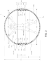
- FIG. 2 is a crosse-sectional view of a main part of the article accommodation container.
- FIG. 3 is an exploded perspective view of the article accommodation container.
- the article accommodation container 1 comprises a body portion 10 composed of a first main component 11 and a second main component 12 capable of being connected to each other, as shown in FIGS. 1 and 2 .
- the first main component 11 and the second main component 12 form a spherical shape on the outer surface 10us formed in a state where the first man component 11 and the second main component 12 are connected to each other.
- the first main component 11 includes a substantially hemispherical main body 11a and a cylindrical projecting portion 11b extending from the main body 11a (also see FIG. 3 ).
- the projecting portion 11b constitutes a connecting portion 10j which is connected to the second main component 12.
- the projecting portion 11b has a first end portion 11e constituting a peripheral edge portion of a first opening 11h on its protruding tip end side thereof, and an annular convex ridge portion 11c is formed on an outer peripheral surface 11f of the projecting portion 11b along the circumferential direction of the outer peripheral surface 11f.
- This convex ridge portion 11c is formed at a position closer to the first end portion 11e than a protruding base end side from which the projecting portion 11b projects.
- the projecting portion 11b is provided with a second end portion 11d having a step in the intersecting direction (orthogonal direction in this embodiment) with respect to the outer peripheral surface 11f of the projecting portion 11b at the protruding base end side of the projecting portion 11b.
- the maximum outer diameter the outer peripheral surface 11f which forms the outer periphery of the first end portion 11e is smaller than the maximum outer diameter of the outer periphery of the second end portion 11d.
- the projecting portion 11b is configured such that the outer diameter d3 of the tip portion of the projecting portion 11b is smaller than the maximum diameter d2 of the main body 11a, and when the projecting portion 11b is fitted inside the second main component 12, they are connected without forming a step on the outer surface 10us as shown in FIG. 1 .
- a concave portion 12c capable of accommodating the convex ridge portion 11c is formed along the circumferential direction of a second opening 12h.
- the position where the concave portion 12c is formed is located inside the second main component 12 away from the third end portion 12b which forms the second opening 12h. Therefore, as shown in FIG. 2 , in the state where the first main component 11 and the second main component 12 are connected to each other, the outer peripheral surface 11f of the projecting portion 11b is in contact with a portion of the inner peripheral surface 10is of the second main component 12 which is located near the second opening 12h.
- the body portion 10 is made of a suitably colored synthetic resin and is configured so that an article C such as a character contained in the internal space SP1 thereof is invisible from the outside when the first main component 11 and the second main component 12 are connected to each other.
- the projecting portion 11b is formed only on the first main component 11, as shown in FIG. 2 , in the connected state where the third end portion 12b is in contact with the second end portion 11d of the first main component 11, the projecting portion 11b is covered by the overlapping portion 12a of the second main component 12 so as not to be visible from the outside.
- the inner surface 10is forms a slightly elongated internal space SP1. That is, it is a space where a substantially hemispherical shapes are connected above and below to the cylindrical space SP2 surrounded by an inner peripheral surfaces 11g of the projecting portion 11b, a virtual face including the lower end side curved line 11i of the inner peripheral surface 11g, and a virtual face including the first end portion 11e.
- the internal space SP1 in a non-spherical shape in this way, it is possible to restrict the rotational movement of the article C contained in the internal space SP1.
- FIG. 3 is an exploded perspective view of the article accommodation container 1. As shown in FIG. 3 , two substantially rectangular cutout portions 12k are formed and positioned so as to be 180 degrees apart on the third end portion 12b of the second main component 12.
- the connection state between the second main component 12 and the first main component 11 includes a state where the third end portion 12b is in contact with the first end portion 11e (initial connection state or final connection released state), and an engaged state where the third end portion 12b is in contact with the second end portion 11d (see FIG. 2 )).
- a certain length (a length L2 in a connection direction) required for a slide movement in the connection direction is secured between the initial state of insertion and connection and the final state of insertion and connection.
- the engaged connection state is stably maintained, and as described later, the disassembly operation of the body portion 10 can be easily performed.
- the size of the rise of the projecting portion 11b influences its operability depending on its relationship with the length in the connection direction (the length D1 of the maximum diameter of the body portion 10) of the first main component 11 and the second main component 12 in the connected state.
- the length L2 of the projecting portion 11b is a certain size or more, the maintenance of the engaged state and the operability of release of the connection are improved.
- the relationship between the length L2 the projecting portion 11b in the connection direction thereof and the length D1 of the maximum diameter of the body portion 10 improves an operability thereof when the length L2 is configured to be 1/5 or more of the length D1.
- the material of the body portion 10 is synthetic resin (PVC, PC, etc.), and the length D1 of the maximum diameter thereof is in a range of 20.0 mm to 80.0 mm, and the thickness thereof is in a range of 1.00 mm to 3.00 mm.
- the length L2 in the connection direction of the projecting portion 11b is 1/3 or more of the maximum length L1 in the connection direction of the first main component 11.
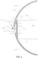
- FIG. 4 is an enlarged sectional view showing an example of how to open (how to release the connection) the article accommodation container 1.
- a fingertip 50 is hooked in the cutout portion 12k, and the overlapping portion 12a of the second main component 12 is separated from the projecting portion 11b of the first main component 11.
- the overlapping portion 12a elastically deforms outwardly from the body portion 10, so that the convex ridge portion 11c and the concave portion 12c are partially separated from each other, thereby making it easier to release the engagement of the convex ridge portion 11c and the concave portion 12c.
- FIG. 5 is another example of an enlarged sectional view showing how to open the article accommodation container 1.
- the cutout portion 12k is not necessarily used.
- the connection release operation can be performed by pressing the outer surface 10us of the body portion 10. In this case, as shown in FIG. 5 , for example, on the side of the second main component 12, the outer surface 10us is pressed toward the inside of the container.
- the position to be pressed may not necessarily be the position shown in FIG. 5 , and it may be possible to press a portion on a side of the first main component 11 instead of the portion of the side of the second main component 12.
- the pressing point may not necessarily be one point, and two or more points may be pressed by fingertips 50.
- a release method for using the pressing operation shown in FIG. 5 and the pulling operation of the cutout portion 12k shown in FIG. 4 simultaneously may be adopted.
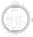
- FIG. 6 is a sectional view illustrating an example where the article accommodation container 1 is covered with a confection 20.
- the article accommodation container 1 is covered with the confection 20 while containing an articles C in the internal space SP1.
- the entire body portion 10 is covered with the confection 20.
- the article can be taken from the article accommodation container 1 by breaking and eating the confection 20.
- a gap SP3 is provided between the outer surface 10us of the body portion 10 and the confection 20, allowing the body portion 10 to oscillate within the confection 20. Since the body portion 10 is covered with confection 20, it is necessary to prevent the confection 20 from being damaged by accidentally breaking it into the two components, that is, the first main component 11 and the second main component 12, before the body portion 10 is picked up by the consumer.
- this problem can be avoided when the length L2 of the projecting portion 11b in the connection direction is or greater than 1/5 of the length D1 of the maximum diameter of the body portion 10. Additionally, this configuration facilitates the separation operation (opening operation) of the first main component 11 and the second main component if needed.
- the body portion 10 of the article accommodating container 1 is formed by connecting the two components, that is, the first main component 11 and the second main component 12 of the article accommodating container 1, and the length L2 in the connection direction of the projecting portion 11b which forms the connecting portion 10j protruding in the connection direction of the connecting portion 10j is set to 1/5 or more of the maximum diameter length D1 of the body portion 10, so that the overlapping length between the first main component 11 and the second main component 12 can be increased.
- the length L2 of the projecting portion 11b is set to 1/3 or more of the maximum length L1 of the first main component 11, the connection strength can be increased.
- the projecting portion 11b is provided only on the side of the first main component 11, and regarding the shape of the outside (outer surface 10us) of the connecting portion 10j, since the first main component 11 is covered by the second main component 12, the overlap portion 12a of the second main component 12 can form part of the spherical outer surface 10us.
- the projecting portion 11b includes a second end portion 11d which forms a step protruding outward from the outer peripheral surface 11f of the projecting portion 11b at its protruding base end side, so that the third end portion 12b of the opening (second opening 12h) of the second main component 12 can be brought into contact with the second end portion 11d.
- the projecting portion 11b can be covered with the overlap portion 12a of the second main component 12 thereby creating a connection state where the projecting portion 11b is not visible from the outside.
- the cutout portions 12k are formed at the third end portion 12b, it is possible to hook a fingertip 50 when the connecting portion 10j is taken off. As a result, it is possible to easily open the body portion 10. Moreover, by providing the cutout portions 12k, it is possible to adjust the rigidity of the third end portion 12b and change the strength of the connection.
- the annular convex ridge portion 11c extending along the circumferential direction is formed on the outer peripheral surface 11f of the projecting portion 11b, the annular convex ridge portion 11c can be fit into the concave portion 12c of the second main component 12, and the connection state of the connecting portion 10j can be locked and maintained. Furthermore, since the position where and the convex ridge portion11c is formed is on the tip side of the projecting portion 11b which is closer to the first end portion 11e, the displacement amount (displacement toward the inside of the container) due to elastic deformation of the projecting portion 11b can be increased.
- the body portion 10 is configured to be deformable by pressing the outer surface 10us of the body portion 10, it is possible to easily release the engagement of the connecting portion 10j due to the positional deviation of the convex ridge portion 11c and the concave portions 12c caused by pressing the body portion 10.
- the body portion 10 is configured to have an internal space SP1 including a portion of the inner surface 10is which does not form a spherical surface, such as a cylindrical shape, it is possible to regulate the rotational movement of the article C accommodated in the internal space SP1.
- the body portion 10 is configured so that the article C accommodated therein cannot be viewed from the outside, it is possible to create an anticipation of what the article C contained is therein.
- the confection 20 is coated on the outer surface 10us of the body portion 10, it is possible to enjoy the article C accommodated inside the body portion 10 while it is possible to enjoy eating the confection 20.
- a gap SP3 is formed between the outer surface 10us of the body portion 10 and the confection 20, it is easy to separate the confection 20 from the body portion 10.
- the body portion 10 is configured to be swingable within the confection 20, for example, when shaking the confection 20, the inner surface of the confectionery 20 is hit by the body portion 10, so that a sound can be generated, and it can be enjoyed as a confection 20 which can generate such a sound.
- the embodiments of the present invention are described above, but the present invention can be appropriately modified within the scope of its technical concept.
- the projecting height of the projecting portion 11b is uniform over its entire circumference, but this configuration is not limited thereto, and the protrusion height may change so as to slope appropriately.
Landscapes
- Engineering & Computer Science (AREA)
- Mechanical Engineering (AREA)
- Ceramic Engineering (AREA)
- Food Science & Technology (AREA)
- Polymers & Plastics (AREA)
- Chemical & Material Sciences (AREA)
- Life Sciences & Earth Sciences (AREA)
- Containers Having Bodies Formed In One Piece (AREA)
- Details Of Rigid Or Semi-Rigid Containers (AREA)
- Rigid Containers With Two Or More Constituent Elements (AREA)
- Confectionery (AREA)
- Toys (AREA)
- Packages (AREA)
- Bag Frames (AREA)
Abstract
An article accommodating container (1) comprises a body portion (10) which includes a first main component (11) and a second main component (12), which can be connected to each other, wherein the first main component (11) comprises a main body (11a) and a projecting portion (11b), which projects from the main body and forms a connecting portion with the second main component (12), and the length of the projecting portion (11b) in a connecting direction with the first main component (11) is 1/5 or more of the length of a maximum diameter of the body portion in a connected state.
Description
- The disclosure of
Japanese Patent Application No. 2023-071072 filed April 24, 2023 - The present invention relates to an article accommodation container.
- Conventionally, an article accommodation container in a shape of a capsule is used to accommodate an article inside the capsule. For example,
Japanese Utility Patent Application Publication No. S53-110977 - In
Japanese Utility Patent Application Publication No. S53-110977 - Therefore, it is an object of the present invention to provide an article accommodation container having a user-friendly configuration.
- One of the aspects of the present invention is an article accommodation container. The article accommodation container includes a body portion comprising a first main part and a second main part, wherein the first main part and the second main part can be connected to each other. The first main part comprises a body portion, a connecting portion to be connected to the second main part, and a projecting portion which rises from the body portion. The length of projecting portion in a connecting direction of the first main part and the second main part is 1/5 or longer of the maximum diameter of the body portion part in a connecting state where the first main part and the second main part are connected to each other.
- According to the present invention, an article accommodation container having a user-friendly configuration can be provided.
-
-
FIG. 1 is a perspective view of an article accommodation container according to an embodiment of the present invention, wherein an article is accommodated; -
FIG. 2 is a crosse sectional view of a main part of the article accommodation container shown inFIG. 1 ; -
FIG. 3 is an exploded perspective view of the article accommodation container shown inFIG. 1 ; -
FIG. 4 is an enlarged crosse-sectional view of the article accommodation container shown inFIG. 1 to show an example on how to open the article accommodation container; -
FIG. 5 is an enlarged cross-sectional view of the main part of the article accommodation container shown inFIG. 1 to show another example on how to open the article accommodation container; and -
FIG. 6 is a cross-sectional view of the article accommodation container shown inFIG. 1 in a state where the article accommodation container is covered with a confection. - An article accommodation container according to an embodiment of the present invention will be explained below, referring to drawings.
FIG. 1 is a perspective view of an article accommodation container according to an embodiment of the present invention, wherein an article is accommodated.FIG. 2 is a crosse-sectional view of a main part of the article accommodation container.FIG. 3 is an exploded perspective view of the article accommodation container. - The
article accommodation container 1 comprises abody portion 10 composed of a firstmain component 11 and a secondmain component 12 capable of being connected to each other, as shown inFIGS. 1 and2 . The firstmain component 11 and the secondmain component 12 form a spherical shape on the outer surface 10us formed in a state where thefirst man component 11 and the secondmain component 12 are connected to each other. The firstmain component 11 includes a substantially hemisphericalmain body 11a and acylindrical projecting portion 11b extending from themain body 11a (also seeFIG. 3 ). The projectingportion 11b constitutes a connectingportion 10j which is connected to the secondmain component 12. - Furthermore, the projecting
portion 11b has afirst end portion 11e constituting a peripheral edge portion of afirst opening 11h on its protruding tip end side thereof, and an annularconvex ridge portion 11c is formed on an outerperipheral surface 11f of the projectingportion 11b along the circumferential direction of the outerperipheral surface 11f. Thisconvex ridge portion 11c is formed at a position closer to thefirst end portion 11e than a protruding base end side from which the projectingportion 11b projects. Additionally, the projectingportion 11b is provided with asecond end portion 11d having a step in the intersecting direction (orthogonal direction in this embodiment) with respect to the outerperipheral surface 11f of the projectingportion 11b at the protruding base end side of the projectingportion 11b. In this configuration, the maximum outer diameter the outerperipheral surface 11f which forms the outer periphery of thefirst end portion 11e is smaller than the maximum outer diameter of the outer periphery of thesecond end portion 11d. In other words, the projectingportion 11b is configured such that the outer diameter d3 of the tip portion of the projectingportion 11b is smaller than the maximum diameter d2 of themain body 11a, and when the projectingportion 11b is fitted inside the secondmain component 12, they are connected without forming a step on the outer surface 10us as shown inFIG. 1 . - On the other hand, on the inner surface 10is of the second
main component 12, aconcave portion 12c capable of accommodating theconvex ridge portion 11c is formed along the circumferential direction of asecond opening 12h. The position where theconcave portion 12c is formed, is located inside the secondmain component 12 away from thethird end portion 12b which forms thesecond opening 12h. Therefore, as shown inFIG. 2 , in the state where the firstmain component 11 and the secondmain component 12 are connected to each other, the outerperipheral surface 11f of the projectingportion 11b is in contact with a portion of the inner peripheral surface 10is of the secondmain component 12 which is located near the second opening 12h. - The
body portion 10 is made of a suitably colored synthetic resin and is configured so that an article C such as a character contained in the internal space SP1 thereof is invisible from the outside when the firstmain component 11 and the secondmain component 12 are connected to each other. - Furthermore, although the projecting
portion 11b is formed only on the firstmain component 11, as shown inFIG. 2 , in the connected state where thethird end portion 12b is in contact with thesecond end portion 11d of the firstmain component 11, the projectingportion 11b is covered by the overlappingportion 12a of the secondmain component 12 so as not to be visible from the outside. - When the first
main component 11 and the secondmain component 12 are connected to each other, as mentioned above, while the outer surface 10us forms a spherical shape as a whole, the inner surface 10is, as shown inFIG. 2 , forms a slightly elongated internal space SP1. That is, it is a space where a substantially hemispherical shapes are connected above and below to the cylindrical space SP2 surrounded by an innerperipheral surfaces 11g of the projectingportion 11b, a virtual face including the lower end sidecurved line 11i of the innerperipheral surface 11g, and a virtual face including thefirst end portion 11e. By configuring the internal space SP1 in a non-spherical shape in this way, it is possible to restrict the rotational movement of the article C contained in the internal space SP1. -
FIG. 3 is an exploded perspective view of thearticle accommodation container 1. As shown inFIG. 3 , two substantiallyrectangular cutout portions 12k are formed and positioned so as to be 180 degrees apart on thethird end portion 12b of the secondmain component 12. - The connection state between the second
main component 12 and the firstmain component 11 includes a state where thethird end portion 12b is in contact with thefirst end portion 11e (initial connection state or final connection released state), and an engaged state where thethird end portion 12b is in contact with thesecond end portion 11d (seeFIG. 2 )). For example, a certain length (a length L2 in a connection direction) required for a slide movement in the connection direction is secured between the initial state of insertion and connection and the final state of insertion and connection. As a result, in the connectingportion 10j, the engaged connection state is stably maintained, and as described later, the disassembly operation of thebody portion 10 can be easily performed. - The size of the rise of the projecting
portion 11b (the length L2 in the connection direction (refer toFIG. 2 )) influences its operability depending on its relationship with the length in the connection direction (the length D1 of the maximum diameter of the body portion 10) of the firstmain component 11 and the secondmain component 12 in the connected state. For example, when the length L2 of the projectingportion 11b is a certain size or more, the maintenance of the engaged state and the operability of release of the connection are improved. The relationship between the length L2 the projectingportion 11b in the connection direction thereof and the length D1 of the maximum diameter of thebody portion 10 improves an operability thereof when the length L2 is configured to be 1/5 or more of the length D1. - Here, the material of the
body portion 10 is synthetic resin (PVC, PC, etc.), and the length D1 of the maximum diameter thereof is in a range of 20.0 mm to 80.0 mm, and the thickness thereof is in a range of 1.00 mm to 3.00 mm. - Furthermore, when compared to the size of the first
main component 11, the length L2 in the connection direction of the projectingportion 11b is 1/3 or more of the maximum length L1 in the connection direction of the firstmain component 11. -
FIG. 4 is an enlarged sectional view showing an example of how to open (how to release the connection) thearticle accommodation container 1. When thearticle accommodation container 1 is opened, as shown inFIG. 4 , afingertip 50 is hooked in thecutout portion 12k, and the overlappingportion 12a of the secondmain component 12 is separated from the projectingportion 11b of the firstmain component 11. As a result, the overlappingportion 12a elastically deforms outwardly from thebody portion 10, so that theconvex ridge portion 11c and theconcave portion 12c are partially separated from each other, thereby making it easier to release the engagement of theconvex ridge portion 11c and theconcave portion 12c. -
FIG. 5 is another example of an enlarged sectional view showing how to open thearticle accommodation container 1. When thearticle accommodation container 1 is opened, in this example, thecutout portion 12k is not necessarily used. For example, the connection release operation can be performed by pressing the outer surface 10us of thebody portion 10. In this case, as shown inFIG. 5 , for example, on the side of the secondmain component 12, the outer surface 10us is pressed toward the inside of the container. - In this case, at the pressing position shown in
FIG. 5 , the side near thefirst end portion 11e, which is an opposite side to thethird end portion 12b, is pressed, thereby causing the pressed portion (lower side of the fingertip 50) to be elastically deformed inward into the container. With this deformation, the inner surface of the upper end side of the overlappingportion 12a comes into contact with thefirst end portion 11e, and this contact portion acts as a fulcrum, causing thethird end portion 12b to move away from thesecond end portion 11d. As a result, theconvex ridge portion 11c and theconcave portion 12c move in a direction in which they are tend to separate from each other, thereby making it easy to release the engagement. - The position to be pressed may not necessarily be the position shown in
FIG. 5 , and it may be possible to press a portion on a side of the firstmain component 11 instead of the portion of the side of the secondmain component 12. Furthermore, the pressing point may not necessarily be one point, and two or more points may be pressed byfingertips 50. In addition, a release method for using the pressing operation shown inFIG. 5 and the pulling operation of thecutout portion 12k shown inFIG. 4 simultaneously may be adopted. -
FIG. 6 is a sectional view illustrating an example where thearticle accommodation container 1 is covered with aconfection 20. Thearticle accommodation container 1 is covered with theconfection 20 while containing an articles C in the internal space SP1. Theentire body portion 10 is covered with theconfection 20. Additionally, the article can be taken from thearticle accommodation container 1 by breaking and eating theconfection 20. Furthermore, a gap SP3 is provided between the outer surface 10us of thebody portion 10 and theconfection 20, allowing thebody portion 10 to oscillate within theconfection 20. Since thebody portion 10 is covered withconfection 20, it is necessary to prevent theconfection 20 from being damaged by accidentally breaking it into the two components, that is, the firstmain component 11 and the secondmain component 12, before thebody portion 10 is picked up by the consumer. This problem can be avoided when the length L2 of the projectingportion 11b in the connection direction is or greater than 1/5 of the length D1 of the maximum diameter of thebody portion 10. Additionally, this configuration facilitates the separation operation (opening operation) of the firstmain component 11 and the second main component if needed. - As described above, the
body portion 10 of thearticle accommodating container 1 according to the present embodiment is formed by connecting the two components, that is, the firstmain component 11 and the secondmain component 12 of thearticle accommodating container 1, and the length L2 in the connection direction of the projectingportion 11b which forms the connectingportion 10j protruding in the connection direction of the connectingportion 10j is set to 1/5 or more of the maximum diameter length D1 of thebody portion 10, so that the overlapping length between the firstmain component 11 and the secondmain component 12 can be increased. As a result, it is possible to provide such anarticle accommodating container 1 with good handling properties in which it is easy to maintain the connection state of the connectingportion 10j and it is easy to release the connection. Furthermore, by setting the length L2 of the projectingportion 11b to 1/3 or more of the maximum length L1 of the firstmain component 11, the connection strength can be increased. - In the present embodiment, the projecting
portion 11b is provided only on the side of the firstmain component 11, and regarding the shape of the outside (outer surface 10us) of the connectingportion 10j, since the firstmain component 11 is covered by the secondmain component 12, theoverlap portion 12a of the secondmain component 12 can form part of the spherical outer surface 10us. - In the present embodiment, the projecting
portion 11b includes asecond end portion 11d which forms a step protruding outward from the outerperipheral surface 11f of the projectingportion 11b at its protruding base end side, so that thethird end portion 12b of the opening (second opening 12h) of the secondmain component 12 can be brought into contact with thesecond end portion 11d. As a result, the projectingportion 11b can be covered with theoverlap portion 12a of the secondmain component 12 thereby creating a connection state where the projectingportion 11b is not visible from the outside. - In the present embodiment, since the
cutout portions 12k are formed at thethird end portion 12b, it is possible to hook afingertip 50 when the connectingportion 10j is taken off. As a result, it is possible to easily open thebody portion 10. Moreover, by providing thecutout portions 12k, it is possible to adjust the rigidity of thethird end portion 12b and change the strength of the connection. - In the present embodiment, since the annular
convex ridge portion 11c extending along the circumferential direction is formed on the outerperipheral surface 11f of the projectingportion 11b, the annularconvex ridge portion 11c can be fit into theconcave portion 12c of the secondmain component 12, and the connection state of the connectingportion 10j can be locked and maintained. Furthermore, since the position where and the convex ridge portion11c is formed is on the tip side of the projectingportion 11b which is closer to thefirst end portion 11e, the displacement amount (displacement toward the inside of the container) due to elastic deformation of the projectingportion 11b can be increased. As a result, it is possible to easily change the position in the projecting direction of theconvex ridge portion 11c at time when theconvex ridge portion 11c and theconcave portion 12c are engaged with each other and at time when the engagement thereof is released, thereby improving the operability of connection! release of the connection. - In the present embodiment, since the
body portion 10 is configured to be deformable by pressing the outer surface 10us of thebody portion 10, it is possible to easily release the engagement of the connectingportion 10j due to the positional deviation of theconvex ridge portion 11c and theconcave portions 12c caused by pressing thebody portion 10. - In the present embodiment, since the
body portion 10 is configured to have an internal space SP1 including a portion of the inner surface 10is which does not form a spherical surface, such as a cylindrical shape, it is possible to regulate the rotational movement of the article C accommodated in the internal space SP1. - Furthermore, in the present embodiment, since the
body portion 10 is configured so that the article C accommodated therein cannot be viewed from the outside, it is possible to create an anticipation of what the article C contained is therein. - In the present embodiment, since the
confection 20 is coated on the outer surface 10us of thebody portion 10, it is possible to enjoy the article C accommodated inside thebody portion 10 while it is possible to enjoy eating theconfection 20. - Furthermore, in the present embodiment, since a gap SP3 is formed between the outer surface 10us of the
body portion 10 and theconfection 20, it is easy to separate theconfection 20 from thebody portion 10. Moreover, since thebody portion 10 is configured to be swingable within theconfection 20, for example, when shaking theconfection 20, the inner surface of theconfectionery 20 is hit by thebody portion 10, so that a sound can be generated, and it can be enjoyed as aconfection 20 which can generate such a sound. - Thus, the embodiments of the present invention are described above, but the present invention can be appropriately modified within the scope of its technical concept. For example, in the above embodiment, the projecting height of the projecting
portion 11b is uniform over its entire circumference, but this configuration is not limited thereto, and the protrusion height may change so as to slope appropriately. - As described above, the following are described in the present specification:
- (1) An article accommodating container comprises: a body portion made up of first and second main components, which can be connected to each other, wherein the first main component comprises a main body and a projecting portion, which projects from the main body and forms a connecting portion with the second main component, and the length of the projecting portion in a direction in which the connecting portion is connected to the first main component is 1/5 or more of the length of the maximum diameter of the body portion in a connected state.
- (2) In the article accommodating container according to (1), a length of the projecting portion in the direction in which the projecting portion is connected to the first main component is 1/3 or more of the maximum length of the first main component in the connecting direction.
- (3) In the article accommodating container according to (1) or (2), the projecting portion is provided on only the first main component within the first main component and the second main component.
- (4) In the article accommodating container according to any one of (1) - (3), an outer surface of the body portion is in a spherical shape in a state where the first main component and the second main component are connected to each other.
- (5) In the article accommodating container according to any one of (1) - (4), the first main component and the second main component are hollow and the inner shape of first main component and that of the second main component are different from each other.
- (6) In the article accommodating container according to any one of (1) - (5), a first opening is formed in the first main component, and the projecting portion includes a first end portion, which forms a peripheral edge of the first opening on a tip side thereof, and the main body includes a second end portion configured to have a step in a direction intersecting the outer peripheral surface of the projecting portion at a base end side of the projecting portion.
- (7) In the article accommodating container according to any one of (1) - (6), the second main component includes a second opening and a third end portion, which forms a peripheral edge of the second opening, and a connected state of the second main component and the first main component includes a state where the third end portion is in contact with the first end portion, and a state where the third end portion is in contact with the second end portion.
- (8) In the article accommodating container according to any one of (1) - (7), the projecting portion is visible from the outside in a state where the third end portion of the second main component is in contact with the second end portion of the first main component.
- (9) In the article accommodating container according to either (7) - (8), a cutout portion is formed in the third end portion of the second main component.
- (10) In the article accommodating container according to any one of (6) - (9), a maximum length of an outer peripheral of the first end portion is shorter than a maximum length of an outer periphery of the second end portion.
- (11) In the article accommodating container according to any one of (6) - (10), an annular convex ridge portion is formed on the outer periphery of the projecting portion along a circumferential direction of the outer periphery.
- (12) In the article accommodating container according to (11), the convex ridge portion is formed at a position closer to the first end portion.
- (13) In the article accommodating container according to either (11) or (12), a concave portion capable of receiving the convex ridge portion is formed in the second main component.
- (14) In the article accommodating container according to any one of (1) - (13), the body portion is deformable by pressing an outer surface thereof.
- (15) In the article accommodating container according to any one of (1) - (14), the outer periphery of the projecting portion is in contact with the an inner surface of the second main component in a state where the first main component and the second main component are connected to each other.
- (16) In the article accommodating container according to any one of (1) - (15), the outer surface of the main body forms a spherical surface as a whole, and an inner space, which does not form a spherical surface, is configured by an inner surface thereof, in a state where the first main component and the second main component are connected to each other.
- (17) In the article accommodating container according to (16), the inner space includes a cylindrically shaped space.
- (18) In the article accommodating container according to any one of (1) - (17), the main body is configured so that an article accommodated inside the body portion is invisible from an outside, in a state where the first main component and the second main component are connected to each other.
- (18) In the article accommodating container according to any one of (1) - (18), an outer surface of the body portion is entirely covered with a confection.
- (19) In the article accommodating container according to (19), a gap is formed between the outer surface of the body portion and the confection, and the body portion is swingable inside the confection.
Claims (20)
- An article accommodating container comprising:a body portion which includes a first main component and a second main component, which can be connected to each other,wherein the first main component comprises a main body and a projecting portion, which projects from the main body and forms a connecting portion with the second main component, andthe length of the projecting portion in a connecting direction with the first main component is 1/5 or more of the length of a maximum diameter of the body portion in a connected state.
- The article accommodating container according to claim 1, wherein a length of the projecting portion in the connecting direction is 1/3 or more of a maximum length of the first main component in the connecting direction.
- The article accommodating container according to claim 2, wherein the projecting portion is provided on only the first main component.
- The article accommodating container according to claim 3, wherein an outer surface of the body portion is in a spherical shape in state where the first main component and the second main component are connected to each other.
- The article accommodating container according to claim 4, wherein the first main component and the second main component are hollow, and an inner shape of the first main component and that of the second main component have different outer shapes.
- The article accommodating container according to claim 5, wherein a first opening is formed in the first main component, and the projecting portion includes a first end portion, which forms a peripheral edge portion of the first opening on a tip side thereof, and the main body includes a second end portion, which is configured to have a step in a direction intersecting an outer peripheral surface of the projecting portion on a base end side of the projecting portion.
- The article accommodating container according to claim 6, wherein the second main component includes a second opening and a third end portion, which forms a peripheral edge portion of the second opening, and a connected state of the second main component and the first main components includes a state where the third end portion is in contact with the first end portion, and a state where the third end portion is in contact with the second end portion.
- The article accommodating container according to claim 7, wherein the projecting portion is visible from an outside in a state where the third end portion of the second main component is in contact with the second end portion of the first main component.
- The article accommodating container according to claim 7, wherein a cutout portion is formed in the third end portion of the second main component.
- The article accommodating container according to claim 6, wherein a maximum length of an outer peripheral of the first end portion is shorter than a maximum length of an outer periphery of the second end portion.
- The article accommodating container according to claim 6, wherein an annular convex ridge portion is formed on the outer peripheral surface of the projecting portion along a circumferential direction of the outer peripheral surface.
- The article accommodating container according to claim 11, wherein the convex ridge portion is formed at a position closer to the first end portion.
- The article accommodating container according to claim 12, wherein a concave portion capable of receiving the convex ridge portion is formed in the second main component.
- The article accommodating container according to claim 1, wherein the body portion is deformable by pressing an outer surface thereof.
- The article accommodating container according to claim 1, wherein an outer peripheral surface of the projecting portion is brought in contact with the an inner surface of the second main component in a state where the first main component and the second main component are connected to each other.
- The article accommodating container according to claim 1, wherein the outer surface of the body portion forms a spherical surface as a whole, and an inner space, which does not form a spherical surface, is configured by part of an inner surface thereof, in a state where the first main component and the second main component are connected to each other.
- The article accommodating container according to claim 16, wherein the inner space includes a cylindrically shaped space.
- The article accommodating container according to claim 1, wherein the body portion is configured so that an article accommodated inside the body portion is invisible from an outside, in a state where the first main component and the second main component are connected to each other.
- The article accommodating container according to claim 1, wherein an outer surface of the body portion is entirely covered with a confection.
- The article accommodating container according to claim 19, wherein a gap is formed between the outer surface of the body portion and the confection, and the body portion is swingable inside the confection.
Applications Claiming Priority (1)
| Application Number | Priority Date | Filing Date | Title |
|---|---|---|---|
| JP2023071072A JP7847562B2 (en) | 2023-04-24 | 2023-04-24 | Article storage container |
Publications (1)
| Publication Number | Publication Date |
|---|---|
| EP4458711A1 true EP4458711A1 (en) | 2024-11-06 |
Family
ID=90544999
Family Applications (1)
| Application Number | Title | Priority Date | Filing Date |
|---|---|---|---|
| EP24167392.0A Pending EP4458711A1 (en) | 2023-04-24 | 2024-03-28 | Article accommodation contrainer |
Country Status (7)
| Country | Link |
|---|---|
| US (1) | US12545499B2 (en) |
| EP (1) | EP4458711A1 (en) |
| JP (1) | JP7847562B2 (en) |
| KR (1) | KR20240156947A (en) |
| CN (1) | CN118022351A (en) |
| TW (1) | TWI878033B (en) |
| WO (1) | WO2024224865A1 (en) |
Citations (6)
| Publication number | Priority date | Publication date | Assignee | Title |
|---|---|---|---|---|
| JPS53110977A (en) | 1977-03-10 | 1978-09-28 | Matsushita Electric Ind Co Ltd | Ultrafiltration membrane |
| JPS635571U (en) * | 1986-06-24 | 1988-01-14 | ||
| WO1993000267A1 (en) * | 1991-06-27 | 1993-01-07 | Ferrero S.P.A. | A container for surprise gifts and the like, for example, for chocolate eggs |
| US5792496A (en) * | 1997-01-10 | 1998-08-11 | Fekete; Ferenc | Edible shell/thermoplastic container system |
| FR2829110B1 (en) * | 2001-08-30 | 2005-01-07 | Distrib Automatique Moderne | HOLLOW BALL FOR PACKAGING AT LEAST ONE SMALL OBJECT |
| JP2023071072A (en) | 2021-11-10 | 2023-05-22 | エナジーサポート株式会社 | Lower electrode for cylindrical cutout |
Family Cites Families (16)
| Publication number | Priority date | Publication date | Assignee | Title |
|---|---|---|---|---|
| US3720342A (en) * | 1971-02-08 | 1973-03-13 | Continental Can Co | Safety closure |
| JPS53110977U (en) | 1977-02-15 | 1978-09-05 | ||
| US4221293A (en) * | 1979-04-09 | 1980-09-09 | Design Accessories Inc. | Container for facial tissues |
| US4765501A (en) * | 1987-09-02 | 1988-08-23 | Joe Kao | Toy container |
| EP0454785B1 (en) * | 1989-01-23 | 1997-03-26 | RUDELL, Elliot A. | Game and ball with water-releasing device |
| US4936479A (en) * | 1989-04-17 | 1990-06-26 | Dan Levy | Hamburger holder |
| JPH0761466A (en) * | 1993-08-25 | 1995-03-07 | Towa Japan:Kk | Bullet storage capsule |
| US6050438A (en) * | 1996-06-27 | 2000-04-18 | Parkway Machine Corporation | Spherical dispensing capsule |
| JP4730986B2 (en) * | 1999-05-07 | 2011-07-20 | 日本クラウンコルク株式会社 | Synthetic resin capsule container |
| JP2000302149A (en) | 1999-07-30 | 2000-10-31 | Runasuuru:Kk | Storage case |
| SI1529731T1 (en) * | 2003-11-06 | 2011-11-30 | Magic Production Group M P G S A | A container for gifts |
| US20060201941A1 (en) * | 2005-03-11 | 2006-09-14 | Hung-Ming Lee | Sphere container |
| TWM361493U (en) * | 2009-01-23 | 2009-07-21 | Fu Sheng Foods Co Ltd | Candy container |
| JP5992374B2 (en) * | 2013-08-02 | 2016-09-14 | 株式会社バンダイ | Container for goods |
| US20220315271A1 (en) * | 2019-12-19 | 2022-10-06 | T-Arts Company, Ltd. | Toy container |
| JP7095159B1 (en) * | 2021-06-07 | 2022-07-04 | 株式会社バンダイ | toy |
-
2023
- 2023-04-24 JP JP2023071072A patent/JP7847562B2/en active Active
-
2024
- 2024-02-29 TW TW113107195A patent/TWI878033B/en active
- 2024-03-07 KR KR1020240032381A patent/KR20240156947A/en active Pending
- 2024-03-11 CN CN202410276210.7A patent/CN118022351A/en active Pending
- 2024-03-14 WO PCT/JP2024/010062 patent/WO2024224865A1/en not_active Ceased
- 2024-03-24 US US18/614,679 patent/US12545499B2/en active Active
- 2024-03-28 EP EP24167392.0A patent/EP4458711A1/en active Pending
Patent Citations (6)
| Publication number | Priority date | Publication date | Assignee | Title |
|---|---|---|---|---|
| JPS53110977A (en) | 1977-03-10 | 1978-09-28 | Matsushita Electric Ind Co Ltd | Ultrafiltration membrane |
| JPS635571U (en) * | 1986-06-24 | 1988-01-14 | ||
| WO1993000267A1 (en) * | 1991-06-27 | 1993-01-07 | Ferrero S.P.A. | A container for surprise gifts and the like, for example, for chocolate eggs |
| US5792496A (en) * | 1997-01-10 | 1998-08-11 | Fekete; Ferenc | Edible shell/thermoplastic container system |
| FR2829110B1 (en) * | 2001-08-30 | 2005-01-07 | Distrib Automatique Moderne | HOLLOW BALL FOR PACKAGING AT LEAST ONE SMALL OBJECT |
| JP2023071072A (en) | 2021-11-10 | 2023-05-22 | エナジーサポート株式会社 | Lower electrode for cylindrical cutout |
Also Published As
| Publication number | Publication date |
|---|---|
| US12545499B2 (en) | 2026-02-10 |
| CN118022351A (en) | 2024-05-14 |
| JP7847562B2 (en) | 2026-04-17 |
| WO2024224865A1 (en) | 2024-10-31 |
| TWI878033B (en) | 2025-03-21 |
| KR20240156947A (en) | 2024-10-31 |
| US20240351776A1 (en) | 2024-10-24 |
| JP2024156531A (en) | 2024-11-06 |
| TW202442538A (en) | 2024-11-01 |
Similar Documents
| Publication | Publication Date | Title |
|---|---|---|
| CN112891957B (en) | Doll type toys | |
| JP5014351B2 (en) | Surprise container | |
| US6537131B1 (en) | Realistic doll head mounting assembly | |
| US20060162133A1 (en) | Button | |
| JP7614118B2 (en) | Capsule toy container | |
| US12545499B2 (en) | Article accommodation contrainer | |
| CN206880323U (en) | Cosmetics containers | |
| EP2628404A1 (en) | Slide fastener, top stop for slide fasteners and slide fastener production method | |
| JP5331720B2 (en) | Double container | |
| JP4079625B2 (en) | Capsule container | |
| JP7290392B2 (en) | packaging container | |
| US20050223527A1 (en) | Pressure botton | |
| JPH11321868A (en) | Storage case | |
| JP6770776B2 (en) | Containers for external preparations and external products using them | |
| US20040237584A1 (en) | Backside decoration element for pin-type earring | |
| JP2022073071A (en) | Double container | |
| HK40111403A (en) | Article storage container | |
| KR20180125931A (en) | Cosmetic vessel | |
| EP4026784A1 (en) | Hinge cap and hinge cap set | |
| GB2065606A (en) | A case for cosmetic products | |
| JP7676767B2 (en) | double container | |
| JPH0739522U (en) | Catch for piercing | |
| JP6964911B1 (en) | Pressure regulating valve | |
| JP2018150055A (en) | capsule | |
| JP2002172887A (en) | Cap with clip |
Legal Events
| Date | Code | Title | Description |
|---|---|---|---|
| PUAI | Public reference made under article 153(3) epc to a published international application that has entered the european phase |
Free format text: ORIGINAL CODE: 0009012 |
|
| STAA | Information on the status of an ep patent application or granted ep patent |
Free format text: STATUS: REQUEST FOR EXAMINATION WAS MADE |
|
| 17P | Request for examination filed |
Effective date: 20240328 |
|
| AK | Designated contracting states |
Kind code of ref document: A1 Designated state(s): AL AT BE BG CH CY CZ DE DK EE ES FI FR GB GR HR HU IE IS IT LI LT LU LV MC ME MK MT NL NO PL PT RO RS SE SI SK SM TR |