EP4458708A1 - Packaging blank for forming a package and package formed from a packaging blank - Google Patents
Packaging blank for forming a package and package formed from a packaging blank Download PDFInfo
- Publication number
- EP4458708A1 EP4458708A1 EP24171101.9A EP24171101A EP4458708A1 EP 4458708 A1 EP4458708 A1 EP 4458708A1 EP 24171101 A EP24171101 A EP 24171101A EP 4458708 A1 EP4458708 A1 EP 4458708A1
- Authority
- EP
- European Patent Office
- Prior art keywords
- transversal
- crease line
- crease
- packaging blank
- line
- Prior art date
- Legal status (The legal status is an assumption and is not a legal conclusion. Google has not performed a legal analysis and makes no representation as to the accuracy of the status listed.)
- Granted
Links
Images

Classifications
-
- B—PERFORMING OPERATIONS; TRANSPORTING
- B65—CONVEYING; PACKING; STORING; HANDLING THIN OR FILAMENTARY MATERIAL
- B65D—CONTAINERS FOR STORAGE OR TRANSPORT OF ARTICLES OR MATERIALS, e.g. BAGS, BARRELS, BOTTLES, BOXES, CANS, CARTONS, CRATES, DRUMS, JARS, TANKS, HOPPERS, FORWARDING CONTAINERS; ACCESSORIES, CLOSURES, OR FITTINGS THEREFOR; PACKAGING ELEMENTS; PACKAGES
- B65D5/00—Rigid or semi-rigid containers of polygonal cross-section, e.g. boxes, cartons or trays, formed by folding or erecting one or more blanks made of paper
- B65D5/42—Details of containers or of foldable or erectable container blanks
- B65D5/4266—Folding lines, score lines, crease lines
-
- B—PERFORMING OPERATIONS; TRANSPORTING
- B65—CONVEYING; PACKING; STORING; HANDLING THIN OR FILAMENTARY MATERIAL
- B65D—CONTAINERS FOR STORAGE OR TRANSPORT OF ARTICLES OR MATERIALS, e.g. BAGS, BARRELS, BOTTLES, BOXES, CANS, CARTONS, CRATES, DRUMS, JARS, TANKS, HOPPERS, FORWARDING CONTAINERS; ACCESSORIES, CLOSURES, OR FITTINGS THEREFOR; PACKAGING ELEMENTS; PACKAGES
- B65D5/00—Rigid or semi-rigid containers of polygonal cross-section, e.g. boxes, cartons or trays, formed by folding or erecting one or more blanks made of paper
- B65D5/02—Rigid or semi-rigid containers of polygonal cross-section, e.g. boxes, cartons or trays, formed by folding or erecting one or more blanks made of paper by folding or erecting a single blank to form a tubular body with or without subsequent folding operations, or the addition of separate elements, to close the ends of the body
- B65D5/029—Rigid or semi-rigid containers of polygonal cross-section, e.g. boxes, cartons or trays, formed by folding or erecting one or more blanks made of paper by folding or erecting a single blank to form a tubular body with or without subsequent folding operations, or the addition of separate elements, to close the ends of the body the tubular body presenting a special shape
-
- B—PERFORMING OPERATIONS; TRANSPORTING
- B65—CONVEYING; PACKING; STORING; HANDLING THIN OR FILAMENTARY MATERIAL
- B65D—CONTAINERS FOR STORAGE OR TRANSPORT OF ARTICLES OR MATERIALS, e.g. BAGS, BARRELS, BOTTLES, BOXES, CANS, CARTONS, CRATES, DRUMS, JARS, TANKS, HOPPERS, FORWARDING CONTAINERS; ACCESSORIES, CLOSURES, OR FITTINGS THEREFOR; PACKAGING ELEMENTS; PACKAGES
- B65D5/00—Rigid or semi-rigid containers of polygonal cross-section, e.g. boxes, cartons or trays, formed by folding or erecting one or more blanks made of paper
- B65D5/02—Rigid or semi-rigid containers of polygonal cross-section, e.g. boxes, cartons or trays, formed by folding or erecting one or more blanks made of paper by folding or erecting a single blank to form a tubular body with or without subsequent folding operations, or the addition of separate elements, to close the ends of the body
- B65D5/06—Rigid or semi-rigid containers of polygonal cross-section, e.g. boxes, cartons or trays, formed by folding or erecting one or more blanks made of paper by folding or erecting a single blank to form a tubular body with or without subsequent folding operations, or the addition of separate elements, to close the ends of the body with end-closing or contents-supporting elements formed by folding inwardly a wall extending from, and continuously around, an end of the tubular body
-
- B—PERFORMING OPERATIONS; TRANSPORTING
- B65—CONVEYING; PACKING; STORING; HANDLING THIN OR FILAMENTARY MATERIAL
- B65D—CONTAINERS FOR STORAGE OR TRANSPORT OF ARTICLES OR MATERIALS, e.g. BAGS, BARRELS, BOTTLES, BOXES, CANS, CARTONS, CRATES, DRUMS, JARS, TANKS, HOPPERS, FORWARDING CONTAINERS; ACCESSORIES, CLOSURES, OR FITTINGS THEREFOR; PACKAGING ELEMENTS; PACKAGES
- B65D5/00—Rigid or semi-rigid containers of polygonal cross-section, e.g. boxes, cartons or trays, formed by folding or erecting one or more blanks made of paper
- B65D5/40—Rigid or semi-rigid containers of polygonal cross-section, e.g. boxes, cartons or trays, formed by folding or erecting one or more blanks made of paper specially constructed to contain liquids
-
- B—PERFORMING OPERATIONS; TRANSPORTING
- B65—CONVEYING; PACKING; STORING; HANDLING THIN OR FILAMENTARY MATERIAL
- B65D—CONTAINERS FOR STORAGE OR TRANSPORT OF ARTICLES OR MATERIALS, e.g. BAGS, BARRELS, BOTTLES, BOXES, CANS, CARTONS, CRATES, DRUMS, JARS, TANKS, HOPPERS, FORWARDING CONTAINERS; ACCESSORIES, CLOSURES, OR FITTINGS THEREFOR; PACKAGING ELEMENTS; PACKAGES
- B65D5/00—Rigid or semi-rigid containers of polygonal cross-section, e.g. boxes, cartons or trays, formed by folding or erecting one or more blanks made of paper
- B65D5/42—Details of containers or of foldable or erectable container blanks
- B65D5/72—Contents-dispensing means
- B65D5/74—Spouts
- B65D5/746—Spouts formed separately from the container
-
- B—PERFORMING OPERATIONS; TRANSPORTING
- B65—CONVEYING; PACKING; STORING; HANDLING THIN OR FILAMENTARY MATERIAL
- B65D—CONTAINERS FOR STORAGE OR TRANSPORT OF ARTICLES OR MATERIALS, e.g. BAGS, BARRELS, BOTTLES, BOXES, CANS, CARTONS, CRATES, DRUMS, JARS, TANKS, HOPPERS, FORWARDING CONTAINERS; ACCESSORIES, CLOSURES, OR FITTINGS THEREFOR; PACKAGING ELEMENTS; PACKAGES
- B65D75/00—Packages comprising articles or materials partially or wholly enclosed in strips, sheets, blanks, tubes or webs of flexible sheet material, e.g. in folded wrappers
- B65D75/40—Packages formed by enclosing successive articles, or increments of material, in webs, e.g. folded or tubular webs, or by subdividing tubes filled with liquid, semi-liquid, or plastic materials
- B65D75/44—Individual packages cut from webs or tubes
- B65D75/48—Individual packages cut from webs or tubes containing liquids, semiliquids, or pastes, e.g. cushion-shaped packages
-
- B—PERFORMING OPERATIONS; TRANSPORTING
- B65—CONVEYING; PACKING; STORING; HANDLING THIN OR FILAMENTARY MATERIAL
- B65D—CONTAINERS FOR STORAGE OR TRANSPORT OF ARTICLES OR MATERIALS, e.g. BAGS, BARRELS, BOTTLES, BOXES, CANS, CARTONS, CRATES, DRUMS, JARS, TANKS, HOPPERS, FORWARDING CONTAINERS; ACCESSORIES, CLOSURES, OR FITTINGS THEREFOR; PACKAGING ELEMENTS; PACKAGES
- B65D85/00—Containers, packaging elements or packages, specially adapted for particular articles or materials
- B65D85/70—Containers, packaging elements or packages, specially adapted for particular articles or materials for materials not otherwise provided for
- B65D85/72—Containers, packaging elements or packages, specially adapted for particular articles or materials for materials not otherwise provided for for edible or potable liquids, semiliquids, or plastic or pasty materials
-
- B—PERFORMING OPERATIONS; TRANSPORTING
- B65—CONVEYING; PACKING; STORING; HANDLING THIN OR FILAMENTARY MATERIAL
- B65D—CONTAINERS FOR STORAGE OR TRANSPORT OF ARTICLES OR MATERIALS, e.g. BAGS, BARRELS, BOTTLES, BOXES, CANS, CARTONS, CRATES, DRUMS, JARS, TANKS, HOPPERS, FORWARDING CONTAINERS; ACCESSORIES, CLOSURES, OR FITTINGS THEREFOR; PACKAGING ELEMENTS; PACKAGES
- B65D85/00—Containers, packaging elements or packages, specially adapted for particular articles or materials
- B65D85/70—Containers, packaging elements or packages, specially adapted for particular articles or materials for materials not otherwise provided for
- B65D85/72—Containers, packaging elements or packages, specially adapted for particular articles or materials for materials not otherwise provided for for edible or potable liquids, semiliquids, or plastic or pasty materials
- B65D85/80—Containers, packaging elements or packages, specially adapted for particular articles or materials for materials not otherwise provided for for edible or potable liquids, semiliquids, or plastic or pasty materials for milk
Definitions
- the present invention relates to a packaging blank, in particular having a multilayer structure, for forming a package filled with a pourable product, in particular a pourable food product.
- the present invention also relates to a package filled with a pourable product, in particular a pourable food product, and being formed from a packaging blank.
- liquid or pourable food products such as fruit juice, UHT (ultra-high-temperature treated) milk, wine, tomato sauce, etc.
- UHT ultra-high-temperature treated milk
- wine tomato sauce
- etc. are sold in packages made of sterilized packaging material.
- a typical example is the parallelepiped-shaped package for liquid or pourable food products known as Tetra Brik Aseptic (registered trademark), which is made by sealing and folding a laminated packaging blank.
- the packaging blank has a multilayer structure comprising a fibrous base layer, e.g. of paper or cardboard, covered on both sides with layers of heat-seal plastic material, e.g. polyethylene.
- the packaging blank also comprises a layer of oxygen-barrier material (an oxygen-barrier layer), e.g. an aluminum foil, which is superimposed on a layer of heat-seal plastic material, and is in turn covered with another layer of heat-seal plastic material forming the inner face of the package eventually contacting the food product.
- Packages of this sort are normally produced on fully automatic packaging apparatuses, which form the packages from respective packaging blanks.
- These packaging blanks can be provided in the form of single packaging blanks or in form of a web, which is formed from a plurality of successively arranged packaging blanks.
- the packaging apparatus In the case of the packaging apparatus being designed to form the packages from a web, the packaging apparatus advances and sterilizes the web, which is then formed into a tube and filled with the pourable product before the tube is formed into individual sealed packages.
- the packaging blanks are provided with a plurality of crease lines.
- a packaging blank has a rectangular shape and is delimited by a first longitudinal boundary edge, a second longitudinal boundary edge, a first transversal boundary edge and a second transversal boundary edge.
- a typical packaging blank also comprises a top crease pattern configured to form a top portion of the package and a bottom crease pattern configured to form a bottom portion of the package.
- the top crease pattern comprises at least a first transversal crease line and a second transversal crease line and the bottom crease pattern comprises at least a third transversal crease line and a fourth transversal crease line.
- the top crease pattern comprises a first transversal crease line and a second transversal seal line and a plurality of auxiliary crease lines and inclined crease lines intersecting the first transversal crease line and the second transversal crease line.
- Number 1 in Figure 1 indicates a package formed from a packaging blank 2 (see Figure 2 ).
- each package 1 is formed from one respective packaging blank 2 by means of an automatic packaging machine.
- the automatic packaging machine is configured to form packages 1 from the respective packaging blanks 2 and to fill packages 1 with a pourable product, in particular a pourable food product such as pasteurized milk, fruit juice, wine, tomato sauce, etc.
- packaging blanks 2 may have a multilayer structure.
- each packaging blank 2 may comprise at least a layer of fibrous material, such as e.g. a paper or cardboard layer, and at least two layers of heat-seal plastic material, e.g. polyethylene, interposing the layer of fibrous material in between one another.
- fibrous material such as e.g. a paper or cardboard layer
- heat-seal plastic material e.g. polyethylene
- One of these two layers of heat-seal plastic material may define an inner face of the respective package 1 formed from the respective packaging blank 2 and eventually contacting the pourable product.
- each packaging blank 2 may also comprise a layer of gas- and light-barrier material, e.g. aluminum foil or ethylene vinyl alcohol (EVOH) film, in particular being arranged between one of the layers of the heat-seal plastic material and the layer of fibrous material.
- gas- and light-barrier material e.g. aluminum foil or ethylene vinyl alcohol (EVOH) film
- EVOH ethylene vinyl alcohol
- packaging blank 2 may also comprise a further layer of heat-seal plastic material being interposed between the layer of gas- and light-barrier material and the layer of fibrous material.
- packaging blanks 2 may be provided in the form of a web.
- the web may be formed from a plurality of successively arranged packaging blanks 2.
- each repeat unit i.e. the respective packaging blank 2 forms the precursor of one respective package 1.
- the packaging machine may be configured to produce packages 1 from the web such that each package 1 results from one respective packaging blank 2.
- each packaging blank 2 may comprise a desired pattern/decoration.
- Each packaging blank 2 may be designed to form a package 1 comprising:
- each first package portion 3, preferentially the first wall, and each second package portion 4, preferentially the second wall may define respectively a bottom portion, preferentially a bottom wall, and a top portion, preferentially a top wall, of the respective package 1.
- each intermediate package portion 5 may be interposed between the respective first package portion 3 and the respective second package portion 4.
- each package 1 is in its nominal position (i.e. when being used by a user in an intended manner)
- the user recognizes first package portion 3 as the bottom portion and second package portion 4 as the top portion.
- each second package portion 4 may be defined as the portion of the package that can be manipulated such to allow for the outpouring of the pourable product.
- second package portion 4 may be manipulated so as to obtain a pouring opening or second package portion 4 may comprise an opening device 6 (e.g. a cap), which can be manipulated.
- each intermediate portion 5 may be defined to be gripped by a user.
- each first package portion 3, preferentially the first wall, may define a support surface of the respective package 1, which may be designed to be put in contact with a support, such as e.g. a shelf, when, in use, being e.g. exposed within a sales point or when being stored.
- a support such as e.g. a shelf
- each second package portion 4, preferentially the respective second wall may be inclined with respect to one of the respective longitudinal axis A and/or the respective first package portion 3, preferentially the respective first wall. More preferentially, each second package portion 4, preferentially the respective second wall, may define a slanted top.
- each packaging blank 2 may comprise:
- each transversal axis C may be perpendicular to the respective longitudinal axis B.
- each longitudinal axis B may intersect the respective transversal axis C within a centre point of the respective packaging blank 2.
- each packaging blank 2 may extend within a plane spanned by longitudinal axis B and transversal axis C.
- each packaging blank 2 may have a (substantially) 2-dimensional shape, i.e. respective extensions of each packaging blank 2 along longitudinal axis B and transversal axis C may be (significantly) larger than a thickness of packaging blank 2. In other words, the thickness of packaging blank 2 may be neglectable in comparison to the respective extensions along longitudinal axis B and transversal axis C.
- each packaging blank 2 may have a rectangular or square shape.
- first direction D1 may be parallel to transversal axis C.
- each first longitudinal boundary edge 10 and each second longitudinal boundary edge 11 may be connected to and interposed between the respective first transversal boundary edge 12 and the respective second transversal boundary edge 13.
- each first longitudinal boundary edge 10 and each second longitudinal boundary edge 11 may be arranged at an angle of about 90° with respect to the respective first transversal boundary edge 12 and the respective second transversal boundary edge 13.
- each packaging blank 2 being arranged singularly, i.e. separated from the other packaging blanks 2, the respective first longitudinal boundary edge 10, the respective second longitudinal boundary edge 11, the respective first transversal boundary edge 12 and the respective second transversal boundary edge 13 may be real edges.
- each first transversal boundary edge 12 of one packaging blank 2 may be adjacent to, or coincide with, the respective second transversal boundary edge 13 of another packaging blank 2.
- each first longitudinal boundary edge 10 of one packaging blank 2 may be adjacent to, or coincide with, the respective second longitudinal boundary edge 11 of another packaging blank 2.
- each longitudinal axis B may define the respective longitudinal axis A of the respective package 1 formed from the respective packaging blank 2.
- each packaging blank 2 may comprise a top crease pattern 14 configured to form the respective second package portion 4, preferentially the respective top portion, of the respective package 1.
- top crease pattern 14 may be configured to form the respective second wall, preferentially the respective second wall and flaps attached to the respective second wall.
- packaging blank 2 may also comprise a bottom crease pattern 15 configured to form the respective first package portion 3, preferentially the respective bottom portion, of the respective package 1.
- bottom crease pattern 15 may be configured to form the respective first wall, preferentially the respective first wall and flaps attached to the respective first wall.
- each top crease pattern 14 may define a respective top region and each bottom crease pattern 15 may define a respective bottom region of the respective packaging blank 2.
- each top crease pattern 14 comprises at least a first transversal crease line 16 and a second transversal crease line 17 extending transversally to longitudinal axis B of the respective packaging blank 2.
- each first transversal crease line 16 and the respective second transversal crease line 17 are displaced from one another along second direction D2.
- each first transversal crease line 16 is interposed between the respective first transversal boundary edge 12 and second transversal crease line 17.
- each first transversal crease line 16 is closer to the respective first transversal boundary edge 12 than the respective second transversal crease line 17.
- each second transversal crease line 17 may be closer to the centre point of the respective packaging blank 2 than the respective first transversal crease line 16.
- no further transversal crease line being or having at least portions perpendicular to the respective longitudinal axis B are interposed between the respective first transversal boundary edge 12 and the respective first transversal crease line 16.
- each second transversal crease line 17 may comprise:
- one lateral portion 21 may be arranged closer to first longitudinal boundary edge 10 than the other lateral portion 21 and the other lateral portion 21 may be arranged closer to second longitudinal boundary edge 11 than the one lateral portion 21.
- each lateral portion 21 may have a rectilinear shape and/or may be perpendicular to longitudinal axis B.
- central portion 22 may have a rectilinear shape and/or may be perpendicular to longitudinal axis B.
- central portion 22 may have a shape differing from a rectilinear one, e.g. central portion 22 may be curved or may have at least a curved part.
- each inclined portion 23 may have a rectilinear shape.
- each lateral portion 21 may intersect the respective inclined portion 23 (i.e. lateral portion 21 and the respective inclined portion 23 contact one another).
- each lateral portion 21 may not intersect the respective inclined portion 23, i.e. respective endpoints of each lateral portion 21 and of the respective inclined portion 23 do not touch each other or, in other words, a respective free space is interposed between each lateral portion 21 and the respective inclined portion 23.
- each lateral portion 21 defines a respective imaginary endless line 24 comprising the respective lateral portion 21 and the respective inclined portion 23 defines an imaginary inclined endless line 25 comprising the respective inclined portion 23.
- each imaginary endless line 24 and the respective imaginary inclined endless line 25 may intersect at a respective intersection point 26.
- each lateral portion 21 and the respective inclined portion 23 intersect one another, the respective intersection point 26 corresponds to the respective point of contact.
- top crease pattern 14 also comprises one or more main inclined crease lines 27, preferentially two main inclined crease lines 27, more preferentially exactly two main inclined crease lines 27, being inclined with respect to longitudinal axis B.
- top crease pattern 14 may also comprise one or more auxiliary crease lines 28 extending transversally to main inclined crease lines 27 and/or parallel to longitudinal axis B and/or parallel to the longitudinal boundary edges, preferentially first longitudinal boundary edge 10 and second longitudinal boundary edge 11.
- each auxiliary crease line 28 may be interposed between one respective main inclined crease line 27 and one respective longitudinal boundary edge.
- At least one auxiliary crease line 28 may be interposed between the respective main inclined crease line 27 and first longitudinal boundary edge 10 and another auxiliary crease line 28 may be interposed between the respective main inclined crease line 27 and second longitudinal boundary edge 11.
- each main inclined crease line 27 may be interposed between and/or may extend between first transversal crease line 16 and second transversal crease line 17 intersecting one respective intersection point 26.
- each main inclined crease line 27 may extend from the respective intersection point 26 towards first transversal crease line 16.
- each main inclined crease line 27 may intersects also first transversal crease line 16 at a respective auxiliary intersection point 29.
- each main inclined crease line 27 may extend from the respective intersection point 26 to the respective auxiliary intersection point 29.
- a respective first distance d1 of each intersection point 26 from longitudinal axis B may be larger than a respective second distance d2 of the respective auxiliary intersection point 29 from longitudinal axis B.
- each main inclined crease line 27 may extend from an end adjacent to first transversal crease line 16 towards second transversal crease line 17 and away from longitudinal axis B.
- each auxiliary crease line 28 may extend between first transversal crease line 16 and second transversal crease line 17 without intersecting second transversal crease line 17 and the respective imaginary endless line 24 and the respective intersection point 26 and/or the respective main inclined crease line 27.
- top crease pattern 14 may also comprise one or more auxiliary inclined crease lines 30, each one extending between first transversal crease line 16 and second transversal crease line 17, being interposed between longitudinal axis B and one respective main inclined crease line 27.
- each auxiliary inclined crease line 30 may intersect one respective main inclined crease line 27, more preferentially at the respective auxiliary intersection point 29 and/or on first transversal crease line 16.
- each main inclined crease line 27 and the respective auxiliary inclined crease line 30 may define in collaboration a V-shape.
- each auxiliary inclined crease line 30 may extend between first transversal crease line 16 and second transversal crease line 17 without intersecting second transversal crease line 17 and without intersecting an imaginary line defined by (and comprising) central portion 22.
- each auxiliary crease line 28 may be laterally shifted from the respective intersection point 26 along first direction D1, preferentially towards longitudinal axis B. In other words, each auxiliary crease line 28 may be misaligned from the respective intersection point 26.
- first transversal crease line 16 may have a linear shape and/or may extend parallel to first transversal boundary edge 12.
- top crease pattern 14 may also comprise further linear crease lines 31 parallel to longitudinal axis B and/or auxiliary crease lines 28 and/or the longitudinal boundary edges.
- each further linear crease line 31 may be interposed between longitudinal axis B and one respective auxiliary crease line 28.
- each inclined portion 23 may define together with central portion 22 one respective intersection 32, preferentially independently on whether inclined portion 23 and central portion 22 may contact one another or not.
- the respective intersection 32 may be defined by the respective imaginary inclined endless line 25 and an imaginary extension of central portion 22 or by a point of contact between the respective inclined portion 23 and central portion 22.
- each auxiliary inclined crease line 30 may extend from the respective auxiliary intersection point 29 towards, and preferentially without intersecting, one respective intersection 32.
- each intersection point 26 defines a respective corner 33, preferentially a back corner, of second package portion 4, preferentially of the top portion, of package 1 to be formed from packaging blank 2.
- each intersection 32 may define a respective corner 34, preferentially a front corner, of second package portion 4, preferentially of the top portion, of package 1 to be formed from packaging blank 2.
- each corner 33 may be farther distanced from first package portion 3 than corners 34 when considering a direction parallel to longitudinal axis A.
- bottom crease pattern 15 may be displaced from top crease pattern 14 along second direction D2 and configured to form first package portion 3, preferentially the bottom portion, of package 1.
- bottom crease pattern 15 may comprise at least a third transversal crease line 40 and a fourth transversal crease line 41 extending transversally to longitudinal axis B.
- third transversal crease line 40 may be interposed between second transversal boundary edge 13 and fourth transversal crease line 41.
- fourth transversal crease line 41 may be linear and/or continuous.
- bottom crease pattern 15 may comprise a plurality of additional crease lines 42, preferentially some being parallel and/or some being transversal to longitudinal axis B.
- additional crease lines 42 may be interposed between the respective third transversal crease line 40 and the respective fourth transversal crease line 41.
- one or more additional crease lines 42 may intersect fourth transversal crease line 41 at a respective additional intersection point 43. More preferentially, each additional intersection point 43 is aligned with a respective intersection point 26 or a respective intersection 32.
- top crease pattern 14 and bottom crease pattern 15 may delimit an intermediate region 44 designed to form intermediate package portion 5, preferentially the side wall, of package 1.
- Intermediate region 44 may comprise an intermediate crease pattern 45 at least partially defining a shape of intermediate package portion 5, preferentially the side wall.
- intermediate crease pattern 45 may comprise a plurality of crease lines 46, preferentially aligned according to a desired pattern, the desired pattern at least partially defining the shape of intermediate package portion 5.
- At least one crease line 46 may intersect one respective intersection point 26 or one respective intersection 32, and preferentially also the respective additional intersection point 43.
- each crease line 46 may comprise a respective first inclined portion being inclined with respect to longitudinal axis B and intersecting the respective intersection point 26 or the respective intersection 32, a respective second inclined portion being inclined with respect to longitudinal axis B and intersecting the respective additional intersection point 43 and a linear portion parallel to longitudinal axis B and being interposed between the respective first inclined portion and the respective second inclined portion.
- each packaging blank 2 may comprise a first face and a second face opposite to the first face.
- the second face may be configured to define an inner face of package 1 to be formed, the inner face being configured to be in contact with the pourable product.
- main inclined crease lines 27 may bulge from the first face, or alternatively from the second face.
- main inclined crease lines 27 may be obtained with a creasing device having a male tool interacting with the second face and a female tool interacting with the first face.
- main inclined crease lines 27 may be obtained with a creasing device having a male tool interacting with the first face and a female tool interacting with the second face.
- first transversal crease line 4 and/or second transversal crease line 5 and/or auxiliary crease lines 28 and/or bottom crease pattern 15 may bulge from the first face, or alternatively from the second face.
- first transversal crease line 4 and/or second transversal crease line 5 and/or auxiliary crease lines 28 and/or bottom crease pattern 15 may be obtained with a creasing device having a male tool interacting with the second face and a female tool interacting with the first face.
- first transversal crease line 4 and/or second transversal crease line 5 and/or auxiliary crease lines 28 and/or bottom crease pattern 15 may be obtained with a creasing device having a male tool interacting with the first face and a female tool interacting with the second face.
- number 2' indicates an alternative embodiment of a packaging blank according to the present invention.
- packaging blank 2' is similar to packaging blank 2, the following description is limited to the differences between them, and using the same references, where possible, for identical or corresponding parts.
- packaging blank 2' differs from packaging blank 2 in that main inclined crease lines 27 do not intersect first transversal crease line 16.
- auxiliary inclined crease lines 30 do not intersect first transversal crease line 16.
- each packaging blank 2' may comprise further linear crease lines 47 parallel to longitudinal axis B, intersecting first transversal crease line 16 and having one portion arranged between first transversal crease line 16 and second transversal crease line 17 and another portion arranged between first transversal crease line 16 and first transversal boundary edge 12.
- packaging blank 2 according to the present invention.
- the Applicant has observed that by having main inclined crease lines 27 intersecting the respective intersection point 26 and by having the respective auxiliary crease line 28 not intersecting the respective intersection point 26, formation of packages 1 is facilitated, in particular it is possible to obtain improved corners 33.
Landscapes
- Engineering & Computer Science (AREA)
- Mechanical Engineering (AREA)
- Cartons (AREA)
- Packaging Of Annular Or Rod-Shaped Articles, Wearing Apparel, Cassettes, Or The Like (AREA)
Abstract
Description
- The present invention relates to a packaging blank, in particular having a multilayer structure, for forming a package filled with a pourable product, in particular a pourable food product.
- Advantageously, the present invention also relates to a package filled with a pourable product, in particular a pourable food product, and being formed from a packaging blank.
- As is known, many liquid or pourable food products, such as fruit juice, UHT (ultra-high-temperature treated) milk, wine, tomato sauce, etc., are sold in packages made of sterilized packaging material.
- A typical example is the parallelepiped-shaped package for liquid or pourable food products known as Tetra Brik Aseptic (registered trademark), which is made by sealing and folding a laminated packaging blank. The packaging blank has a multilayer structure comprising a fibrous base layer, e.g. of paper or cardboard, covered on both sides with layers of heat-seal plastic material, e.g. polyethylene. In the case of aseptic packages for long-storage products, such as UHT milk, the packaging blank also comprises a layer of oxygen-barrier material (an oxygen-barrier layer), e.g. an aluminum foil, which is superimposed on a layer of heat-seal plastic material, and is in turn covered with another layer of heat-seal plastic material forming the inner face of the package eventually contacting the food product.
- Packages of this sort are normally produced on fully automatic packaging apparatuses, which form the packages from respective packaging blanks. These packaging blanks can be provided in the form of single packaging blanks or in form of a web, which is formed from a plurality of successively arranged packaging blanks.
- In the case of the packaging apparatus being designed to form the packages from a web, the packaging apparatus advances and sterilizes the web, which is then formed into a tube and filled with the pourable product before the tube is formed into individual sealed packages.
- In order to facilitate the formation and for defining the shape of the packages, the packaging blanks are provided with a plurality of crease lines.
- Typically, a packaging blank has a rectangular shape and is delimited by a first longitudinal boundary edge, a second longitudinal boundary edge, a first transversal boundary edge and a second transversal boundary edge.
- A typical packaging blank also comprises a top crease pattern configured to form a top portion of the package and a bottom crease pattern configured to form a bottom portion of the package. The top crease pattern comprises at least a first transversal crease line and a second transversal crease line and the bottom crease pattern comprises at least a third transversal crease line and a fourth transversal crease line.
- It is known to produce packages having a bottom wall and a top wall being spaced apart from one another along a longitudinal axis of the packages. One variant comes along with the top wall being inclined with respect to the bottom wall; such packages are known as packages provided with a slanted top wall.
- It is known that such packages are produced form packaging blanks having an appropriate top crease pattern. The top crease pattern comprises a first transversal crease line and a second transversal seal line and a plurality of auxiliary crease lines and inclined crease lines intersecting the first transversal crease line and the second transversal crease line.
- Even though the packages formed from such packaging blanks provide for excellent results, a desire is felt in the sector, to further improve the packaging blanks.
- It is therefore an object of the present invention to provide an improved packaging blank.
- It is another object of the present invention to provide an improved package formed from a packaging blank.
- According to the present invention, there is provided a packaging blank as claimed in claim 1.
- Preferred non-limiting embodiments of the packaging blank are claimed in the respective dependent claims.
- According to the present invention, there is also provided a package according to
claim 15. - Two non-limiting embodiments of the present invention will be described by way of example with reference to the accompanying drawings, in which:
-
Figure 1 is a schematic view of a package filled with a pourable product, with parts removed for clarity; -
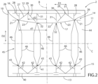
Figure 2 is a plan view of a packaging blank according to a first embodiment of the present invention; -
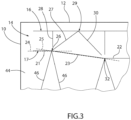
Figure 3 is an enlarged view of a detail of the packaging blank ofFigure 2 ; and -
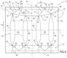
Figure 4 is a plan view of a packaging blank according to a second embodiment of the present invention. - Number 1 in
Figure 1 indicates a package formed from a packaging blank 2 (seeFigure 2 ). - Preferentially, each package 1 is formed from one respective packaging blank 2 by means of an automatic packaging machine.
- The automatic packaging machine is configured to form packages 1 from the
respective packaging blanks 2 and to fill packages 1 with a pourable product, in particular a pourable food product such as pasteurized milk, fruit juice, wine, tomato sauce, etc. - Preferentially,
packaging blanks 2 may have a multilayer structure. - In more detail, each packaging blank 2 may comprise at least a layer of fibrous material, such as e.g. a paper or cardboard layer, and at least two layers of heat-seal plastic material, e.g. polyethylene, interposing the layer of fibrous material in between one another.
- One of these two layers of heat-seal plastic material may define an inner face of the respective package 1 formed from the respective packaging blank 2 and eventually contacting the pourable product.
- Preferably but not necessarily, each packaging blank 2 may also comprise a layer of gas- and light-barrier material, e.g. aluminum foil or ethylene vinyl alcohol (EVOH) film, in particular being arranged between one of the layers of the heat-seal plastic material and the layer of fibrous material. Preferentially but not necessarily, packaging blank 2 may also comprise a further layer of heat-seal plastic material being interposed between the layer of gas- and light-barrier material and the layer of fibrous material.
- According to some preferred non-limiting embodiment,
packaging blanks 2 may be provided in the form of a web. - In more detail, the web may be formed from a plurality of successively arranged
packaging blanks 2. - In other words, the successively arranged
packaging blanks 2 define a plurality of repeat units of the web. In particular, each repeat unit (i.e. the respective packaging blank 2) forms the precursor of one respective package 1. - Preferentially, the packaging machine may be configured to produce packages 1 from the web such that each package 1 results from one respective packaging blank 2.
- In particular, each packaging blank 2 may comprise a desired pattern/decoration.
- Each packaging blank 2 may be designed to form a package 1 comprising:
- a
first package portion 3, preferentially having a first wall; - a
second package portion 4, preferentially having a second wall, displaced fromfirst package portion 3 along a longitudinal axis A of package 1; - an intermediate package portion 5, preferentially having and/or defining a side wall, being (fixedly) connected to and extending from
first package portion 3, preferentially the first wall, andsecond package portion 4, preferentially the second wall. - In more detail, each
first package portion 3, preferentially the first wall, and eachsecond package portion 4, preferentially the second wall, may define respectively a bottom portion, preferentially a bottom wall, and a top portion, preferentially a top wall, of the respective package 1. - Additionally, each intermediate package portion 5 may be interposed between the respective
first package portion 3 and the respectivesecond package portion 4. - Preferentially, when each package 1 is in its nominal position (i.e. when being used by a user in an intended manner), the user recognizes
first package portion 3 as the bottom portion andsecond package portion 4 as the top portion. - Preferentially, each
second package portion 4 may be defined as the portion of the package that can be manipulated such to allow for the outpouring of the pourable product. For example,second package portion 4 may be manipulated so as to obtain a pouring opening orsecond package portion 4 may comprise an opening device 6 (e.g. a cap), which can be manipulated. - Preferentially, each intermediate portion 5 may be defined to be gripped by a user.
- In further detail, each
first package portion 3, preferentially the first wall, may define a support surface of the respective package 1, which may be designed to be put in contact with a support, such as e.g. a shelf, when, in use, being e.g. exposed within a sales point or when being stored. - According to some preferred embodiment, each
second package portion 4, preferentially the respective second wall, may be inclined with respect to one of the respective longitudinal axis A and/or the respectivefirst package portion 3, preferentially the respective first wall. More preferentially, eachsecond package portion 4, preferentially the respective second wall, may define a slanted top. - In more detail, each packaging blank 2 may comprise:
- two longitudinal boundary edges, preferentially a first
longitudinal boundary edge 10 and a secondlongitudinal boundary edge 11, spaced apart from one another along a first direction D1 transversal, preferentially perpendicular, to a longitudinal axis B of the respective packaging blank 2; and - two transversal boundary edges, preferentially a first
transversal boundary edge 12 and a secondtransversal boundary edge 13, spaced apart from one another along a second direction D2 parallel to longitudinal axis B and/or transversal, preferentially perpendicular, to first direction D1 and/or transversal, preferentially perpendicular, to a transversal axis C of the respective packaging blank 2. - Preferentially, each transversal axis C may be perpendicular to the respective longitudinal axis B.
- Preferentially, each longitudinal axis B may intersect the respective transversal axis C within a centre point of the respective packaging blank 2.
- In further detail, each
packaging blank 2 may extend within a plane spanned by longitudinal axis B and transversal axis C. - Moreover, each
packaging blank 2 may have a (substantially) 2-dimensional shape, i.e. respective extensions of eachpackaging blank 2 along longitudinal axis B and transversal axis C may be (significantly) larger than a thickness ofpackaging blank 2. In other words, the thickness of packaging blank 2 may be neglectable in comparison to the respective extensions along longitudinal axis B and transversal axis C. - Preferentially, each
packaging blank 2 may have a rectangular or square shape. - Additionally, first direction D1 may be parallel to transversal axis C.
- Moreover, each first
longitudinal boundary edge 10 and each secondlongitudinal boundary edge 11 may be connected to and interposed between the respective firsttransversal boundary edge 12 and the respective secondtransversal boundary edge 13. - Preferentially, each first
longitudinal boundary edge 10 and each secondlongitudinal boundary edge 11 may be arranged at an angle of about 90° with respect to the respective firsttransversal boundary edge 12 and the respective secondtransversal boundary edge 13. - It should be noted that in the case of each
packaging blank 2 being arranged singularly, i.e. separated from theother packaging blanks 2, the respective firstlongitudinal boundary edge 10, the respective secondlongitudinal boundary edge 11, the respective firsttransversal boundary edge 12 and the respective secondtransversal boundary edge 13 may be real edges. - In the case of
packaging blanks 2 being arranged in the form of aweb 3, the respective firstlongitudinal boundary edge 10 and the respective secondlongitudinal boundary edge 11 may be real edges (as also shown inFigure 2 ) and the respective firsttransversal boundary edge 12 and the respective secondtransversal boundary edge 13 may be imaginary edges. In particular, each firsttransversal boundary edge 12 of onepackaging blank 2 may be adjacent to, or coincide with, the respective secondtransversal boundary edge 13 of anotherpackaging blank 2. - Alternatively, the respective first
transversal boundary edge 12 and the respective secondtransversal boundary edge 13 may be real edges and the respective firstlongitudinal boundary edge 10 and the respective secondlongitudinal boundary edge 11 may be imaginary edges. In particular, each firstlongitudinal boundary edge 10 of onepackaging blank 2 may be adjacent to, or coincide with, the respective secondlongitudinal boundary edge 11 of anotherpackaging blank 2. - Moreover, each longitudinal axis B may define the respective longitudinal axis A of the respective package 1 formed from the
respective packaging blank 2. - With particular reference to
Figure 2 , eachpackaging blank 2 may comprise atop crease pattern 14 configured to form the respectivesecond package portion 4, preferentially the respective top portion, of the respective package 1. - In further detail,
top crease pattern 14 may be configured to form the respective second wall, preferentially the respective second wall and flaps attached to the respective second wall. - Preferentially, packaging blank 2 may also comprise a
bottom crease pattern 15 configured to form the respectivefirst package portion 3, preferentially the respective bottom portion, of the respective package 1. - In further detail,
bottom crease pattern 15 may be configured to form the respective first wall, preferentially the respective first wall and flaps attached to the respective first wall. - In more detail, each
top crease pattern 14 may define a respective top region and eachbottom crease pattern 15 may define a respective bottom region of therespective packaging blank 2. - With particular reference to
Figures 2 and3 , eachtop crease pattern 14 comprises at least a firsttransversal crease line 16 and a secondtransversal crease line 17 extending transversally to longitudinal axis B of therespective packaging blank 2. - Preferentially, each first
transversal crease line 16 and the respective secondtransversal crease line 17 are displaced from one another along second direction D2. - Preferentially, each first
transversal crease line 16 is interposed between the respective firsttransversal boundary edge 12 and secondtransversal crease line 17. In other words, each firsttransversal crease line 16 is closer to the respective firsttransversal boundary edge 12 than the respective secondtransversal crease line 17. - Moreover, each second
transversal crease line 17 may be closer to the centre point of the respective packaging blank 2 than the respective firsttransversal crease line 16. - According to some preferred non-limiting embodiments, no further transversal crease line being or having at least portions perpendicular to the respective longitudinal axis B are interposed between the respective first
transversal boundary edge 12 and the respective firsttransversal crease line 16. - With particular reference to
Figures 2 and3 , each secondtransversal crease line 17 may comprise: - at least two
lateral portions 21 opposed to one another and transversal, preferentially perpendicular, to longitudinal axis B; - at least a
central portion 22; - at least two
inclined portions 23 inclined with respect to longitudinal axis B and each one extending between onerespective lateral portion 21 andcentral portion 22. - Preferentially, one
lateral portion 21 may be arranged closer to firstlongitudinal boundary edge 10 than the otherlateral portion 21 and the otherlateral portion 21 may be arranged closer to secondlongitudinal boundary edge 11 than the onelateral portion 21. - Preferentially, each
lateral portion 21 may have a rectilinear shape and/or may be perpendicular to longitudinal axis B. - According to some preferred non-limiting embodiments,
central portion 22 may have a rectilinear shape and/or may be perpendicular to longitudinal axis B. - Alternatively,
central portion 22 may have a shape differing from a rectilinear one, e.g.central portion 22 may be curved or may have at least a curved part. - According to some preferred embodiments, each
inclined portion 23 may have a rectilinear shape. - According to the embodiment shown, each
lateral portion 21 may intersect the respective inclined portion 23 (i.e.lateral portion 21 and the respectiveinclined portion 23 contact one another). - Alternatively, each
lateral portion 21 may not intersect the respectiveinclined portion 23, i.e. respective endpoints of eachlateral portion 21 and of the respectiveinclined portion 23 do not touch each other or, in other words, a respective free space is interposed between eachlateral portion 21 and the respectiveinclined portion 23. - According to some non-limiting embodiments, each
lateral portion 21 defines a respective imaginaryendless line 24 comprising therespective lateral portion 21 and the respectiveinclined portion 23 defines an imaginary inclinedendless line 25 comprising the respectiveinclined portion 23. - Moreover, each imaginary
endless line 24 and the respective imaginary inclinedendless line 25 may intersect at arespective intersection point 26. - In the case that each
lateral portion 21 and the respectiveinclined portion 23 intersect one another, therespective intersection point 26 corresponds to the respective point of contact. - With reference to
Figures 2 and3 ,top crease pattern 14 also comprises one or more maininclined crease lines 27, preferentially two maininclined crease lines 27, more preferentially exactly two maininclined crease lines 27, being inclined with respect to longitudinal axis B. - Additionally,
top crease pattern 14 may also comprise one or moreauxiliary crease lines 28 extending transversally to maininclined crease lines 27 and/or parallel to longitudinal axis B and/or parallel to the longitudinal boundary edges, preferentially firstlongitudinal boundary edge 10 and secondlongitudinal boundary edge 11. Preferentially, eachauxiliary crease line 28 may be interposed between one respective maininclined crease line 27 and one respective longitudinal boundary edge. - More preferentially, at least one
auxiliary crease line 28 may be interposed between the respective maininclined crease line 27 and firstlongitudinal boundary edge 10 and anotherauxiliary crease line 28 may be interposed between the respective maininclined crease line 27 and secondlongitudinal boundary edge 11. - Moreover, each main
inclined crease line 27 may be interposed between and/or may extend between firsttransversal crease line 16 and secondtransversal crease line 17 intersecting onerespective intersection point 26. - Preferentially, each main
inclined crease line 27 may extend from therespective intersection point 26 towards firsttransversal crease line 16. - Advantageously, each main
inclined crease line 27 may intersects also firsttransversal crease line 16 at a respectiveauxiliary intersection point 29. - According to some preferred embodiments, each main
inclined crease line 27 may extend from therespective intersection point 26 to the respectiveauxiliary intersection point 29. - Preferentially, a respective first distance d1 of each
intersection point 26 from longitudinal axis B may be larger than a respective second distance d2 of the respectiveauxiliary intersection point 29 from longitudinal axis B. - Preferentially, each main
inclined crease line 27 may extend from an end adjacent to firsttransversal crease line 16 towards secondtransversal crease line 17 and away from longitudinal axis B. - Advantageously, each
auxiliary crease line 28 may extend between firsttransversal crease line 16 and secondtransversal crease line 17 without intersecting secondtransversal crease line 17 and the respective imaginaryendless line 24 and therespective intersection point 26 and/or the respective maininclined crease line 27. - According to some possible embodiments,
top crease pattern 14 may also comprise one or more auxiliaryinclined crease lines 30, each one extending between firsttransversal crease line 16 and secondtransversal crease line 17, being interposed between longitudinal axis B and one respective maininclined crease line 27. - Preferentially, each auxiliary
inclined crease line 30 may intersect one respective maininclined crease line 27, more preferentially at the respectiveauxiliary intersection point 29 and/or on firsttransversal crease line 16. - More preferentially, each main
inclined crease line 27 and the respective auxiliaryinclined crease line 30 may define in collaboration a V-shape. - According to some preferred non-limiting embodiments, each auxiliary
inclined crease line 30 may extend between firsttransversal crease line 16 and secondtransversal crease line 17 without intersecting secondtransversal crease line 17 and without intersecting an imaginary line defined by (and comprising)central portion 22. - According to some preferred non-limiting embodiments, each
auxiliary crease line 28 may be laterally shifted from therespective intersection point 26 along first direction D1, preferentially towards longitudinal axis B. In other words, eachauxiliary crease line 28 may be misaligned from therespective intersection point 26. - According to some preferred non-limiting embodiments, first
transversal crease line 16 may have a linear shape and/or may extend parallel to firsttransversal boundary edge 12. - With particular reference to
Figures 2 and3 ,top crease pattern 14 may also comprise furtherlinear crease lines 31 parallel to longitudinal axis B and/orauxiliary crease lines 28 and/or the longitudinal boundary edges. Preferentially, each furtherlinear crease line 31 may be interposed between longitudinal axis B and one respectiveauxiliary crease line 28. - According to some preferred non-limiting embodiments, each
inclined portion 23 may define together withcentral portion 22 onerespective intersection 32, preferentially independently on whetherinclined portion 23 andcentral portion 22 may contact one another or not. Therespective intersection 32 may be defined by the respective imaginary inclinedendless line 25 and an imaginary extension ofcentral portion 22 or by a point of contact between the respectiveinclined portion 23 andcentral portion 22. - Moreover, each auxiliary
inclined crease line 30 may extend from the respectiveauxiliary intersection point 29 towards, and preferentially without intersecting, onerespective intersection 32. - According to some preferred non-limiting embodiments, each
intersection point 26 defines arespective corner 33, preferentially a back corner, ofsecond package portion 4, preferentially of the top portion, of package 1 to be formed from packaging blank 2. - Moreover, each
intersection 32 may define arespective corner 34, preferentially a front corner, ofsecond package portion 4, preferentially of the top portion, of package 1 to be formed from packaging blank 2. - Preferentially, each
corner 33 may be farther distanced fromfirst package portion 3 thancorners 34 when considering a direction parallel to longitudinal axis A. - With particular reference to
Figure 2 ,bottom crease pattern 15 may be displaced fromtop crease pattern 14 along second direction D2 and configured to formfirst package portion 3, preferentially the bottom portion, of package 1. - Preferentially,
bottom crease pattern 15 may comprise at least a thirdtransversal crease line 40 and a fourthtransversal crease line 41 extending transversally to longitudinal axis B. - Preferentially, third
transversal crease line 40 may be interposed between secondtransversal boundary edge 13 and fourthtransversal crease line 41. - Preferentially, fourth
transversal crease line 41 may be linear and/or continuous. - Moreover,
bottom crease pattern 15 may comprise a plurality ofadditional crease lines 42, preferentially some being parallel and/or some being transversal to longitudinal axis B. Preferentially,additional crease lines 42 may be interposed between the respective thirdtransversal crease line 40 and the respective fourthtransversal crease line 41. - Preferentially, one or more
additional crease lines 42 may intersect fourthtransversal crease line 41 at a respectiveadditional intersection point 43. More preferentially, eachadditional intersection point 43 is aligned with arespective intersection point 26 or arespective intersection 32. - Moreover,
top crease pattern 14 andbottom crease pattern 15 may delimit anintermediate region 44 designed to form intermediate package portion 5, preferentially the side wall, of package 1. -
Intermediate region 44 may comprise anintermediate crease pattern 45 at least partially defining a shape of intermediate package portion 5, preferentially the side wall. - Preferentially,
intermediate crease pattern 45 may comprise a plurality ofcrease lines 46, preferentially aligned according to a desired pattern, the desired pattern at least partially defining the shape of intermediate package portion 5. - Preferentially, at least one
crease line 46, more preferentially at least twocrease lines 46, may intersect onerespective intersection point 26 or onerespective intersection 32, and preferentially also the respectiveadditional intersection point 43. - More specifically, each
crease line 46 may comprise a respective first inclined portion being inclined with respect to longitudinal axis B and intersecting therespective intersection point 26 or therespective intersection 32, a respective second inclined portion being inclined with respect to longitudinal axis B and intersecting the respectiveadditional intersection point 43 and a linear portion parallel to longitudinal axis B and being interposed between the respective first inclined portion and the respective second inclined portion. - In further detail, each
packaging blank 2 may comprise a first face and a second face opposite to the first face. In particular, the second face may be configured to define an inner face of package 1 to be formed, the inner face being configured to be in contact with the pourable product. - According to some preferred embodiments, main
inclined crease lines 27 may bulge from the first face, or alternatively from the second face. - In the first case, main
inclined crease lines 27 may be obtained with a creasing device having a male tool interacting with the second face and a female tool interacting with the first face. In the second case, maininclined crease lines 27 may be obtained with a creasing device having a male tool interacting with the first face and a female tool interacting with the second face. - Preferentially, first
transversal crease line 4 and/or second transversal crease line 5 and/orauxiliary crease lines 28 and/orbottom crease pattern 15 may bulge from the first face, or alternatively from the second face. - In the first case, first
transversal crease line 4 and/or second transversal crease line 5 and/orauxiliary crease lines 28 and/orbottom crease pattern 15 may be obtained with a creasing device having a male tool interacting with the second face and a female tool interacting with the first face. In the second case, firsttransversal crease line 4 and/or second transversal crease line 5 and/orauxiliary crease lines 28 and/orbottom crease pattern 15 may be obtained with a creasing device having a male tool interacting with the first face and a female tool interacting with the second face. - With reference to
Figure 4 , number 2' indicates an alternative embodiment of a packaging blank according to the present invention; as packaging blank 2' is similar to packaging blank 2, the following description is limited to the differences between them, and using the same references, where possible, for identical or corresponding parts. - In particular, packaging blank 2' differs from packaging blank 2 in that main
inclined crease lines 27 do not intersect firsttransversal crease line 16. - Additionally, also auxiliary
inclined crease lines 30 do not intersect firsttransversal crease line 16. - Moreover, each packaging blank 2' may comprise further
linear crease lines 47 parallel to longitudinal axis B, intersecting firsttransversal crease line 16 and having one portion arranged between firsttransversal crease line 16 and secondtransversal crease line 17 and another portion arranged between firsttransversal crease line 16 and firsttransversal boundary edge 12. - The advantages of packaging blank 2 according to the present invention will be clear from the foregoing description.
- In particular, the Applicant has observed that by having main
inclined crease lines 27 intersecting therespective intersection point 26 and by having the respectiveauxiliary crease line 28 not intersecting therespective intersection point 26, formation of packages 1 is facilitated, in particular it is possible to obtainimproved corners 33. - Clearly, changes may be made to packaging blank 2 and 2' as described herein without, however, departing from the scope of protection as defined in the accompanying claims.
Claims (15)
- Packaging blank (2; 2') for forming a package (1) filled with a pourable product comprising:- two longitudinal boundary edges (10; 11) spaced apart from one another along a first direction (D1) transversal to a longitudinal axis (B) of the packaging blank (2; 2'); and- two transversal boundary edges (12; 13) spaced apart from one another along a second direction (D2) parallel to the longitudinal axis (B); and- a top crease pattern (14) configured to form a top portion of the package (1);wherein the top crease pattern (14) comprises at least a first transversal crease line (16) and a second transversal crease line (17) extending transversally to the longitudinal axis (B) of the packaging blank (2; 2'), the first transversal crease line (16) being interposed between one respective transversal boundary edge (10) and the second transversal crease line (17);wherein the second transversal crease line (17) comprises at least two lateral portions (21) opposed to one another and transversal to the longitudinal axis (B), at least a central portion (22) and at least two inclined portions (23) inclined with respect to the longitudinal axis (B) and each one extending between one respective lateral portion (21) and the central portion (22);wherein the top crease pattern (14) comprises one or more main inclined crease lines (27) being inclined with respect to the longitudinal axis (B) and one or more auxiliary crease lines (28) extending transversally to the main inclined crease line (27) and/or parallel to the longitudinal axis (B) and/or parallel to the longitudinal boundary edges (10; 11) and being interposed between one respective main inclined crease line (27) and one respective longitudinal boundary edge (10; 11);wherein each lateral portion (21) defines a respective imaginary endless line (24) comprising the respective lateral portion (21) and the respective inclined portion (23) defines an imaginary inclined endless line (25) comprising the respective inclined portion (23) and intersecting the respective imaginary endless line (23) at an intersection point (26);wherein each main inclined crease line (27) extends between the first transversal crease line (16) and the second transversal crease line (17) intersecting the respective intersection point (26);wherein each auxiliary crease line (28) extends between the first transversal crease line (16) and the second transversal crease line (17) without intersecting the second transversal crease line (17), the imaginary endless line (24), the respective intersection point (26) and the respective main inclined crease line (27).
- Packaging blank according to claim 1, wherein each main inclined crease line (27) intersects also the first transversal crease line (16) at an auxiliary intersection point (29).
- Packaging blank according to claim 2, wherein each main inclined crease line (27) extends from the intersection point (26) to the auxiliary intersection point (29).
- Packaging blank according to claim 2 or 3, wherein a respective first distance (d1) of each intersection point (26) from the longitudinal axis (B) is larger than a respective second distance (d2) of the respective auxiliary intersection point (29) from the longitudinal axis (B).
- Packaging blank according to any one of the preceding claims, wherein each lateral portion (21) and/or each inclined portion (23) intersects the respective intersection point (26).
- Packaging blank according to any one of the preceding claims, wherein the top crease pattern (14) also comprises one or more auxiliary inclined crease lines (30), each one extending between the first transversal crease line (16) and the second transversal crease line (17), being interposed between the longitudinal axis (B) and one respective main inclined crease line (27) and intersecting the respective main inclined crease line (27).
- Packaging blank according to claim 6, wherein each auxiliary inclined crease line (30) intersects the respective main inclined crease line (27) on the first transversal crease line (16).
- Packaging blank according to claim 6 or 7, wherein each auxiliary inclined crease line (30) extends between the first transversal crease line (16) and the second transversal crease line (17) without intersecting the second transversal crease line (17) and an imaginary line defined by the central portion (22).
- Packaging blank according to any one of the preceding claims, and further comprising a bottom crease pattern (15) displaced from the top crease pattern (14) along the second direction (D2) and configured to form a bottom portion of the package (1).
- Packaging blank according to claim 9, wherein the bottom crease pattern (15) comprises at least a third transversal crease line (40) and a fourth transversal crease line (41) extending transversally to the longitudinal axis (B) of the packaging blank (2; 2'), the third transversal crease line (40) being interposed between one transversal boundary edge (13) and the fourth transversal crease line (41) .
- Packaging blank according to claim 9 or 10, wherein the top crease pattern (14) and the bottom crease pattern (15) delimit an intermediate region (44) designed to form a side wall of the package (1);wherein the intermediate region (44) comprises an intermediate crease pattern (45) at least partially defining a shape of the side wall;wherein the intermediate crease pattern (45) comprises a plurality of crease lines (46), at least one intersecting one respective intersection point (26).
- Packaging blank according to any one of the preceding claims, wherein each intersection point (26) defines a corner (33) of a top portion of the package (1) to be formed from the packaging blank (2, 2').
- Packaging blank according to any one of the preceding claims, wherein each auxiliary crease line (28) is laterally shifted from the respective intersection point (26) along the first direction (D1).
- Packaging blank according to any one of the preceding claims, and further comprising a first face and a second face opposite to the first face;wherein the second face is configured to define an inner face of the package (1) to be formed, the inner face being configured to be in contact with the pourable product;wherein each main inclined crease line (27) bulges from the first face or from the second face.
- Package (1) filled with a pourable product formed from a packaging blank (2; 2') according to any one of the preceding claims.
Applications Claiming Priority (1)
| Application Number | Priority Date | Filing Date | Title |
|---|---|---|---|
| IT102023000008994A IT202300008994A1 (en) | 2023-05-05 | 2023-05-05 | PACKAGING DRAFT FOR FORMING A PACKAGE AND PACKAGE MADE UP OF A PACKAGING DRAFT |
Publications (2)
| Publication Number | Publication Date |
|---|---|
| EP4458708A1 true EP4458708A1 (en) | 2024-11-06 |
| EP4458708B1 EP4458708B1 (en) | 2026-05-06 |
Family
ID=87036095
Family Applications (1)
| Application Number | Title | Priority Date | Filing Date |
|---|---|---|---|
| EP24171101.9A Active EP4458708B1 (en) | 2023-05-05 | 2024-04-18 | Packaging blank for forming a package and package formed from a packaging blank |
Country Status (7)
| Country | Link |
|---|---|
| EP (1) | EP4458708B1 (en) |
| JP (1) | JP2026514149A (en) |
| CN (1) | CN121079254A (en) |
| AU (1) | AU2024267919A1 (en) |
| IT (1) | IT202300008994A1 (en) |
| MX (1) | MX2025012540A (en) |
| WO (1) | WO2024231070A1 (en) |
Citations (4)
| Publication number | Priority date | Publication date | Assignee | Title |
|---|---|---|---|---|
| US20100257987A1 (en) * | 2008-01-23 | 2010-10-14 | Tetra Laval Holdings & Finance S.A. | Method for controlling the register between a printed pattern and a three-dimensional pattern on a packaging material |
| WO2019201862A1 (en) * | 2018-04-20 | 2019-10-24 | Tetra Laval Holdings & Finance S.A. | A sheet packaging material for producing a sealed package containing a pourable food product and a sealed package obtained from a sheet packaging material |
| US20210147110A1 (en) * | 2018-04-27 | 2021-05-20 | Nippon Paper Industries Co., Ltd. | Paper container with stopper |
| US20210284379A1 (en) * | 2018-07-16 | 2021-09-16 | Tetra Laval Holdings & Finance S.A. | Method for producing a packaging material |
-
2023
- 2023-05-05 IT IT102023000008994A patent/IT202300008994A1/en unknown
-
2024
- 2024-04-18 AU AU2024267919A patent/AU2024267919A1/en active Pending
- 2024-04-18 EP EP24171101.9A patent/EP4458708B1/en active Active
- 2024-04-18 WO PCT/EP2024/060618 patent/WO2024231070A1/en not_active Ceased
- 2024-04-18 CN CN202480030578.3A patent/CN121079254A/en active Pending
- 2024-04-18 JP JP2025562018A patent/JP2026514149A/en active Pending
-
2025
- 2025-10-21 MX MX2025012540A patent/MX2025012540A/en unknown
Patent Citations (4)
| Publication number | Priority date | Publication date | Assignee | Title |
|---|---|---|---|---|
| US20100257987A1 (en) * | 2008-01-23 | 2010-10-14 | Tetra Laval Holdings & Finance S.A. | Method for controlling the register between a printed pattern and a three-dimensional pattern on a packaging material |
| WO2019201862A1 (en) * | 2018-04-20 | 2019-10-24 | Tetra Laval Holdings & Finance S.A. | A sheet packaging material for producing a sealed package containing a pourable food product and a sealed package obtained from a sheet packaging material |
| US20210147110A1 (en) * | 2018-04-27 | 2021-05-20 | Nippon Paper Industries Co., Ltd. | Paper container with stopper |
| US20210284379A1 (en) * | 2018-07-16 | 2021-09-16 | Tetra Laval Holdings & Finance S.A. | Method for producing a packaging material |
Also Published As
| Publication number | Publication date |
|---|---|
| CN121079254A (en) | 2025-12-05 |
| WO2024231070A1 (en) | 2024-11-14 |
| EP4458708B1 (en) | 2026-05-06 |
| JP2026514149A (en) | 2026-05-01 |
| IT202300008994A1 (en) | 2024-11-05 |
| AU2024267919A1 (en) | 2025-10-09 |
| MX2025012540A (en) | 2025-11-03 |
Similar Documents
| Publication | Publication Date | Title |
|---|---|---|
| US12037167B2 (en) | Sheet packaging material for producing a sealed package containing a pourable food product and a sealed package obtained from a sheet packaging material | |
| US20210237925A1 (en) | A sealed package containing a pourable food product and a sheet packaging material for producing a sealed package containing a pourable food product | |
| US20160325872A1 (en) | Sealed package for pourable food products and a basic unit of sheet packaging material for producing sealed packages for pourable food products | |
| EP4458708B1 (en) | Packaging blank for forming a package and package formed from a packaging blank | |
| EP4328143A1 (en) | Packaging blank for forming a package and package formed from a packaging blank | |
| EP4317002A1 (en) | Packaging blank for forming a package and package formed from a packaging blank | |
| EP4477571A1 (en) | Packaging blank for forming a package, package formed from a packaging blank and package | |
| EP4741305A1 (en) | Packaging blank for forming a package, package formed from a packaging blank and package | |
| EP4556388A1 (en) | Package filled with a pourable product and packaging blank for forming a package | |
| EP4556387A1 (en) | Package filled with a pourable product and packaging blank for forming a package | |
| EP4506272A1 (en) | Package filled with a pourable product and method for forming a package | |
| EP4617188A1 (en) | Package for a pourable product and packaging blank for forming a package | |
| EP4617187A1 (en) | Package for a pourable product | |
| US11932461B2 (en) | Sheet packaging material for producing sealed packages for liquid food products | |
| EP4617184A1 (en) | Package for a pourable product and packaging blank for forming a package | |
| WO2026098986A1 (en) | Packaging blank for forming a package, package formed from a packaging blank and package | |
| EP4678547A1 (en) | Package for a pourable product |
Legal Events
| Date | Code | Title | Description |
|---|---|---|---|
| PUAI | Public reference made under article 153(3) epc to a published international application that has entered the european phase |
Free format text: ORIGINAL CODE: 0009012 |
|
| STAA | Information on the status of an ep patent application or granted ep patent |
Free format text: STATUS: THE APPLICATION HAS BEEN PUBLISHED |
|
| AK | Designated contracting states |
Kind code of ref document: A1 Designated state(s): AL AT BE BG CH CY CZ DE DK EE ES FI FR GB GR HR HU IE IS IT LI LT LU LV MC ME MK MT NL NO PL PT RO RS SE SI SK SM TR |
|
| STAA | Information on the status of an ep patent application or granted ep patent |
Free format text: STATUS: REQUEST FOR EXAMINATION WAS MADE |
|
| 17P | Request for examination filed |
Effective date: 20250506 |
|
| GRAP | Despatch of communication of intention to grant a patent |
Free format text: ORIGINAL CODE: EPIDOSNIGR1 |
|
| STAA | Information on the status of an ep patent application or granted ep patent |
Free format text: STATUS: GRANT OF PATENT IS INTENDED |
|
| INTG | Intention to grant announced |
Effective date: 20260223 |
|
| GRAS | Grant fee paid |
Free format text: ORIGINAL CODE: EPIDOSNIGR3 |
|
| GRAA | (expected) grant |
Free format text: ORIGINAL CODE: 0009210 |
|
| STAA | Information on the status of an ep patent application or granted ep patent |
Free format text: STATUS: THE PATENT HAS BEEN GRANTED |
|
| AK | Designated contracting states |
Kind code of ref document: B1 Designated state(s): AL AT BE BG CH CY CZ DE DK EE ES FI FR GB GR HR HU IE IS IT LI LT LU LV MC ME MK MT NL NO PL PT RO RS SE SI SK SM TR |
|
| REG | Reference to a national code |
Ref country code: CH Ref legal event code: F10 Free format text: ST27 STATUS EVENT CODE: U-0-0-F10-F00 (AS PROVIDED BY THE NATIONAL OFFICE) Effective date: 20260506 Ref country code: GB Ref legal event code: FG4D |