EP4458698A1 - Wrapping method and packer machine for straws, with orientation before the packing - Google Patents
Wrapping method and packer machine for straws, with orientation before the packing Download PDFInfo
- Publication number
- EP4458698A1 EP4458698A1 EP24160230.9A EP24160230A EP4458698A1 EP 4458698 A1 EP4458698 A1 EP 4458698A1 EP 24160230 A EP24160230 A EP 24160230A EP 4458698 A1 EP4458698 A1 EP 4458698A1
- Authority
- EP
- European Patent Office
- Prior art keywords
- straw
- bending
- conveyor
- straws
- bending conveyor
- Prior art date
- Legal status (The legal status is an assumption and is not a legal conclusion. Google has not performed a legal analysis and makes no representation as to the accuracy of the status listed.)
- Pending
Links
Images




Classifications
-
- B—PERFORMING OPERATIONS; TRANSPORTING
- B65—CONVEYING; PACKING; STORING; HANDLING THIN OR FILAMENTARY MATERIAL
- B65B—MACHINES, APPARATUS OR DEVICES FOR, OR METHODS OF, PACKAGING ARTICLES OR MATERIALS; UNPACKING
- B65B19/00—Packaging rod-shaped or tubular articles susceptible to damage by abrasion or pressure, e.g. cigarettes, cigars, macaroni, spaghetti, drinking straws or welding electrodes
- B65B19/34—Packaging other rod-shaped articles, e.g. sausages, macaroni, spaghetti, drinking straws, welding electrodes
-
- B—PERFORMING OPERATIONS; TRANSPORTING
- B31—MAKING ARTICLES OF PAPER, CARDBOARD OR MATERIAL WORKED IN A MANNER ANALOGOUS TO PAPER; WORKING PAPER, CARDBOARD OR MATERIAL WORKED IN A MANNER ANALOGOUS TO PAPER
- B31F—MECHANICAL WORKING OR DEFORMATION OF PAPER, CARDBOARD OR MATERIAL WORKED IN A MANNER ANALOGOUS TO PAPER
- B31F1/00—Mechanical deformation without removing material, e.g. in combination with laminating
- B31F1/0003—Shaping by bending, folding, twisting, straightening, flattening or rim-rolling; Shaping by bending, folding or rim-rolling combined with joining; Apparatus therefor
- B31F1/0006—Bending or folding; Folding edges combined with joining; Reinforcing edges during the folding thereof
- B31F1/0032—Bending or folding; Folding edges combined with joining; Reinforcing edges during the folding thereof of tubes
-
- B—PERFORMING OPERATIONS; TRANSPORTING
- B65—CONVEYING; PACKING; STORING; HANDLING THIN OR FILAMENTARY MATERIAL
- B65B—MACHINES, APPARATUS OR DEVICES FOR, OR METHODS OF, PACKAGING ARTICLES OR MATERIALS; UNPACKING
- B65B35/00—Supplying, feeding, arranging or orientating articles to be packaged
- B65B35/56—Orientating, i.e. changing the attitude of, articles, e.g. of non-uniform cross-section
-
- B—PERFORMING OPERATIONS; TRANSPORTING
- B65—CONVEYING; PACKING; STORING; HANDLING THIN OR FILAMENTARY MATERIAL
- B65B—MACHINES, APPARATUS OR DEVICES FOR, OR METHODS OF, PACKAGING ARTICLES OR MATERIALS; UNPACKING
- B65B63/00—Auxiliary devices, not otherwise provided for, for operating on articles or materials to be packaged
- B65B63/04—Auxiliary devices, not otherwise provided for, for operating on articles or materials to be packaged for folding or winding articles, e.g. gloves or stockings
-
- B—PERFORMING OPERATIONS; TRANSPORTING
- B65—CONVEYING; PACKING; STORING; HANDLING THIN OR FILAMENTARY MATERIAL
- B65B—MACHINES, APPARATUS OR DEVICES FOR, OR METHODS OF, PACKAGING ARTICLES OR MATERIALS; UNPACKING
- B65B9/00—Enclosing successive articles, or quantities of material, e.g. liquids or semiliquids, in flat, folded, or tubular webs of flexible sheet material; Subdividing filled flexible tubes to form packages
- B65B9/02—Enclosing successive articles, or quantities of material between opposed webs
- B65B9/04—Enclosing successive articles, or quantities of material between opposed webs one or both webs being formed with pockets for the reception of the articles, or of the quantities of material
- B65B2009/047—Rotary pocket formers
-
- B—PERFORMING OPERATIONS; TRANSPORTING
- B65—CONVEYING; PACKING; STORING; HANDLING THIN OR FILAMENTARY MATERIAL
- B65B—MACHINES, APPARATUS OR DEVICES FOR, OR METHODS OF, PACKAGING ARTICLES OR MATERIALS; UNPACKING
- B65B9/00—Enclosing successive articles, or quantities of material, e.g. liquids or semiliquids, in flat, folded, or tubular webs of flexible sheet material; Subdividing filled flexible tubes to form packages
- B65B9/02—Enclosing successive articles, or quantities of material between opposed webs
- B65B9/04—Enclosing successive articles, or quantities of material between opposed webs one or both webs being formed with pockets for the reception of the articles, or of the quantities of material
- B65B9/045—Enclosing successive articles, or quantities of material between opposed webs one or both webs being formed with pockets for the reception of the articles, or of the quantities of material for single articles, e.g. tablets
Definitions
- the present invention relates to a wrapping method and a packer machine for straws.
- Straws having an intermediate corrugated portion designed to allow the straw to be bent so that, in use, it takes the shape most suitable for the user are well known.
- a straw is individually packaged (i.e., it is inserted individually into its own wrapping) after being bent into a "U" shape (i.e., by 180°) at the intermediate corrugated portion (the purpose of the bending into a "U" shape is to reduce the overall size of the straw); U-bent straws are typically required to be packaged individually when the straws are to be attached (glued) to the back wall of a beverage container.
- a packer machine known to package straws individually includes: a hopper containing a mass of straws, a drawing drum which takes the straws from the hopper, a bending drum which bends each straw, and a wrapping drum which has a plurality of suction seats, each designed to house a portion of a first continuous (i.e., seamless) band of wrapping material, and a straw.
- Each suction seat of the wrapping drum receives a portion of the first continuous band of wrapping material which is bent into a "U" shape inside the suction seat to define a pocket and then receives, directly from the bending drum, a straw (which places itself inside the pocket).
- the wrapping drum is coupled to an applicator drum which applies (typically by heat-sealing) to the first continuous band of wrapping material a second continuous band of wrapping material which closes the pockets containing the straws. Therefore, a continuous (i.e., seamless) succession of pockets, each containing a straw, is fed from the wrapping drum; this continuous succession of pockets, each containing a straw, in jargon is called a "cartridge belt".
- a dual-line packer machine so that all operations are performed simultaneously on two straws placed side by side.
- a double straw i.e., of double length
- the two “cartridge belts” are not perfectly identical, as they have, relative to one another, a mirror-like symmetry of the straws or of the sheets of wrapping, which complicates the subsequent processing steps, since an automatic machine (for example, a filling machine for the production of single-dose beverage parallelepiped packages) using straws must be adaptable (i.e., flexible) to be able to operate with two different " cartridge belts " .
- an automatic machine for example, a filling machine for the production of single-dose beverage parallelepiped packages
- straws must be adaptable (i.e., flexible) to be able to operate with two different " cartridge belts " .
- Patent application WO2021250715A1 discloses a straw packer machine comprising a feeding unit configured to feed a plurality of paper straws to several processing units configured to automatically perform different processes on the straws, including a deformation to make a bellows, a cut, following the deformation, to obtain an obliquely cut pointed end, a bend at the bellows, and a packaging of each straw.
- the object of the present invention is to provide a wrapping method and a packer machine for straws which allow, by operating on a dual line, to produce two perfectly identical " cartridge belts " .
- the numeral 1 indicates, as a whole, a straw (made of paper or plastic) which is applied to the back of a beverage package.
- the straw 1 has a flat end 2 (which is grasped by the user's lips) and a pointed end 3 (to more effectively break through the cap sealing a dispensing opening of the package).
- the straw 1 has an intermediate corrugated portion 4 at which the straw 1 can be bent easily and without breakage (i.e., elastically) to take, in use, the shape most suitable for the user.
- the straw 1 is individually packaged (i.e., it has been inserted individually into its own wrapping 5, not shown in Figure 1 and shown in Figure 2 ) after being bent into a "U" shape (i.e., by 180°) at the intermediate corrugated portion 4 (the purpose of the bending into a "U" shape is to reduce the overall size of the straw 1 so that it remains within the dimensions of the back wall of the package to which the straw 1 is applied).
- the numeral 6 indicates, as a whole, a packer machine, which receives the straight straws 1 from a manufacturing machine (not shown), corrugates the straws 1, bends the straws 1 into a "U" shape, and inserts the bent straws 1 into corresponding wrappings 5.
- the packer machine 6 comprises a hopper 7, which is suitable for containing a mass of straight straws 1 coming from the manufacturing machine and moving progressively by gravity downwards, that is to say to the bottom of the hopper 7.
- the packer machine 6 could have any buffer or collector for a mass of straws.
- the packer machine 6 could receive the straws in an orderly manner (i.e., not collected in a mass), for example directly from the manufacturing machine.
- the retrieval conveyor 8 which, in an input station S1, retrieves a succession of straight straws 1 and moves them transversely (i.e., perpendicular to a longitudinal axis of the straws 1).
- the retrieval conveyor 8 consists of a drum, which is mounted so that it can rotate around a rotation axis 9 (horizontal and perpendicular to the plane in Figure 3 ) and has a plurality of suction seats, each designed to house a corresponding straight straw 1.
- the retrieval conveyor 8 is a conveyor belt, i.e., it comprises a flexible belt, which is closed like a ring around two end pulleys and supports a plurality of suction seats, each designed to house a corresponding straight straw 1.
- the packer machine 6 comprises a corrugator drum 10, which is mounted so that it can rotate around a rotation axis 11 (parallel to the rotation axis 9), has a plurality of seats, each designed to house a corresponding straight straw 1, and receives the straight straws 1 directly from the retrieval conveyor 8 in a transfer station S2.
- a corrugator device 12 which corrugates the straight straws 1, i.e., it creates the intermediate corrugated portion 4 in each straight straw 1.
- the packer machine 6 could receive straight straws 1 that are already corrugated; in this case, the packer machine 6 does not include the corrugator drum 10.
- the packer machine 6 comprises a bending drum 13, which is mounted so that it can rotate around a rotation axis 14 (parallel to the rotation axis 11), has a plurality of suction seats 15 (shown more clearly in Figures 4-9 ), each designed to house a corresponding initially straight straw 1, and receives the straight straws 1 directly from the corrugator drum 10 in a transfer station S3.
- Bending elements 16 are arranged in a fixed position (i.e., integral with a frame of the packer machine 6 and therefore unmovable) around the rotation axis 14, the former being coupled to the bending drum 13 and interacting with the straws 1 carried by the suction seats to bend the straws 1 into a "U" shape.
- the packer machine 6 comprises a waste drum 17, which is mounted so that it can rotate around a rotation axis 18 (parallel to the rotation axis 14), has a plurality of seats, each designed to house a corresponding U-bent straw 1, receives the straws 1 directly from the bending drum 13 in a transfer station S4, and delivers the bent straws 1 in a transfer station S5 arranged downstream of the transfer station S4 in relation to the rotational direction of the waste drum 17.
- the packer machine 6 comprises a wrapping drum 19, which is mounted so that it can rotate around a rotation axis 20 (parallel to the rotation axis 18), has a plurality of suction seats, each designed to house a portion of a continuous (i.e., seamless) band 21 of wrapping material, and a U-bent straw 1.
- Each suction seat of the wrapping drum 19 receives, in a feeding station S6, a portion of the continuous band 21 of wrapping material which is bent into a "U" shape inside the suction seat to define a pocket and then receives, directly from the waste drum 17 in the transfer station S5, a bent straw 1 (which places itself inside the pocket previously formed in the suction seat).
- the wrapping drum 22 is coupled to an applicator drum 22, which is mounted so that it can rotate around a rotation axis 23 (parallel to the rotation axis 20) and applies (typically by heat-sealing) to the continuous band 21 of wrapping material and in a feeding station S7 a continuous band 24 of wrapping material which closes the pockets containing the bent straws 1. Therefore, a continuous (i.e., seamless) succession of pockets, each containing a bent straw 1, is fed from the wrapping drum 22; this continuous succession of pockets, each containing a bent straw 1, in jargon is called a " cartridge belt " .
- the packer machine 6 comprises an output conveyor 25, which receives the " cartridge belt “ (that is, it receives a continuous band of wrappings 5 containing respective bent straws 1) from the wrapping drum 19 and moves the " cartridge belt " to an output of the packer machine 6.
- the whole packer machine 6 operates with a law of continuous motion, that is, with movements at a normally constant speed (when the productivity of the packer machine 6 is stable or in steady, and therefore non-transient, state).
- the packer machine 6 operates on a dual line, that is to say it processes two straws 1 at a time, arranged head first, side by side (that is, axially aligned with each other).
- the retrieval conveyor 8 has a set of pairs of suction seats (axially aligned with each other) to retrieve two straight straws 1 at a time from the output mouth of the hopper 7
- the corrugator drum 10 has a set of pairs of seats (axially aligned with each other), which simultaneously receive two straight straws 1 from the retrieval conveyor 8, simultaneously corrugate two straws 1 together with the corrugator device 12, and simultaneously deliver two straight straws 1 to the bending drum 13.
- the bending drum 13 has a set of pairs of suction seats 15 (axially aligned with each other or side-by-side and aligned along a direction perpendicular to a moving direction of the bending drum 13), which simultaneously receive two straight straws 1 from the corrugator drum 10, simultaneously bend two straws 1, and simultaneously deliver two bent straws 1 to the waste drum 17.
- the waste drum 17 has a set of pairs of seats (axially aligned with each other), which simultaneously receive two bent straws 1 from the bending drum 13 and simultaneously deliver two bent straws 1 to the wrapping drum 19.
- the wrapping drum 19 has a set of pairs of suction seats (axially aligned with each other), which simultaneously receive two bent straws 1 from the waste drum 17, simultaneously create two wrappings 5 (operating with two continuous bands 21 and 24 of double-width wrapping material), and simultaneously deliver two wrappings 5 to the output conveyor 25.
- the output conveyor 25 has a set of pairs of suction seats (axially aligned with each other), which simultaneously receive two wrappings 5 (and thus two " cartridge belts ”) from the wrapping drum 19.
- the hopper 7 contains straight straws 1 of double length (i.e., twice the length of a straw 1 coming out of the packer machine 6), which are cut in half by a cutting device 26 coupled to the retrieval conveyor 8.
- the bending drum 14 has two sets of seats 15 arranged side by side: one set of seats 15 is arranged on the right-hand side and the other set of seats 15 is arranged on the left-hand side. That is, the bending drum 13 is provided with a plurality of pairs of seats 15 that are side-by-side and aligned axially (i.e., perpendicular to the moving direction of the bending drum 13). In the transfer station S3, each seat 15 contains a respective straw 1 which is still completely straight (as shown in Figure 4 ).
- each seat 15 contains a respective straw, which has been bent by 180° by respective bending elements 16 and still has the bent portion (i.e., the " short " portion) protruding radially cantilevered (as shown in Figure 5 ).
- each seat 15 contains a respective straw 1, which has been bent by 180° by a bending element 16 and then rotated by 90° by an orientation system 27 (shown in Figures 7-10 ) to also arrange the bent portion (i.e., the " short " portion) inside the seat 15.
- the orientation system 27 rotates by 90° the straws 1 of one set of seats 15 in one direction and rotates by 90° the straws 1 of the other set of seats 15 in an opposite direction; that is, if the straws 1 of one set of seats 15 are rotated by 90° clockwise, then the straws 1 of the other set of seats 15 are rotated by 90° anticlockwise.
- the straws 1 located in the set of seats 15 on the right have an orientation symmetrically opposite to the straws 1 located in the set of seats 15 on the left.
- the orientation system 27 comprises two different orienting devices 28 and 29, each arranged on a respective side of the bending drum 13 and operating with a respective set of seats 15; that is, the orienting device 28 is arranged on the left side of the bending drum 13 and operates with the set of seats 15 on the left side, and the orienting device 29 is arranged on the right side of the bending drum 13 and operates with the set of seats 15 on the right side.
- the orienting devices 28 and 29 are configured to rotate the respective straws 1 in opposite directions.
- the orienting device 28 is completely passive (i.e., it has no moving parts) and comprises a fixed orienting element 30 (i.e., which is rigidly fixed to a frame of the packer machine 6 and does not rotate with the bending drum 13), which has an arc-of-a-circle shape, is arranged around part of the periphery of the bending drum 13, and has a variable distance from the bending drum 13 (in particular a distance decreasing along the rotational direction of the bending drum 13), so as to progressively force a bent straw 1, located in a respective seat 15, to completely enter the seat 15 by rotating by 90° in a direction contrary to the rotational direction of the bending drum 13.
- a fixed orienting element 30 i.e., which is rigidly fixed to a frame of the packer machine 6 and does not rotate with the bending drum 13
- a variable distance from the bending drum 13 in particular a distance decreasing along the rotational direction of the bending drum 13
- the orienting device 28 rotates the bent straws 1 by 90° in a direction contrary to the rotational direction of the bending drum 13, and this type of rotation can be obtained by using the movement of the bending drum 13 by making the straws 13 enter in contact with a " fixed obstacle " (the orienting element 30).
- the orienting element 30 can be integrated, i.e., form a single, seamless body, with a respective bending element 16.
- the orienting device 29 is partially active (i.e., it has moving parts) and comprises an orienting belt 31, which is closed like a ring around two pulleys 32 and 33, is arranged near the periphery of the bending drum 13, and has an active branch 34 facing the periphery of the bending drum 13.
- the active branch 34 of the orienting belt 31 has a variable distance from the bending drum 13 (in particular a distance decreasing along the rotational direction of the bending drum 13) and, in use, moves in the same rotational direction as the bending drum 13 at a higher speed than the peripheral speed of the seats 15 of the bending drum 13, so as to progressively force a bent straw 1, located in a respective seat 15, to completely enter the seat 15 by rotating by 90° in the same rotational direction as the bending drum 13.
- the orienting device 29 rotates the bent straws by 90° in the same rotational direction as the bending drum 13, and this type of rotation can only be achieved by " accelerating " the bent straws 1 (through the active branch 33 of the orienting belt 31) relative to the rotation of the bending drum 13.
- the pulley 32 is idle whereas the pulley 33 is motorized and receives the motion from the same motor such that it causes the rotation of the bending drum 13, so that the moving speed of the orienting belt 31 always corresponds to the peripheral speed of the seats 15 of the bending drum 13, to prevent both rotating the bent straws 1 by less than 90° (if the moving speed of the orienting belt 31 is too slow) and rotating the bent straws 1 too fast, subjecting the bent straws 1 to excessive mechanical stress 1 (if the moving speed of the orienting belt 31 is too fast).
- the two pulleys 32 and 33 of the orienting device 29 are arranged at different distances from the periphery of the bending drum 13 so as to allow the orienting belt 31 to gain a variable distance from the bending drum 13 (in particular a distance decreasing along the rotational direction of the bending drum 13); in particular, the pulley 32 arranged upstream relative to the rotational direction of the bending drum 13 is farther from the periphery of the bending drum 13, whereas the pulley 33 arranged downstream relative to the rotational direction of the bending drum 13 is closer to the periphery of the bending drum 13.
- the orienting device 29 also comprises a fixed accompanying element 35 (i.e., which is rigidly fixed to a frame of the packer machine 6 and does not rotate with the bending drum 13), which has an arc-of-a-circle shape, is arranged around part of the periphery of the bending drum 13, and is arranged upstream of the orienting belt 31 relative to the rotational direction of the bending drum 13 to contain the straws 1 inside the seats 15 before the action of the orienting belt 31.
- a fixed accompanying element 35 i.e., which is rigidly fixed to a frame of the packer machine 6 and does not rotate with the bending drum 13
- the orienting device 29 also comprises a fixed accompanying element 36 (i.e., which is rigidly fixed to a frame of the packer machine 6 and does not rotate with the bending drum 13), which has an arc-of-a-circle shape, is arranged around part of the periphery of the bending drum 13, and is arranged downstream of the orienting belt 31 relative to the rotational direction of the bending drum 13 to contain the straws 1 inside the seats 15 after the action of the orienting belt 31.
- a fixed accompanying element 36 i.e., which is rigidly fixed to a frame of the packer machine 6 and does not rotate with the bending drum 13
- the orienting device 29 also comprises a fixed accompanying element 36 (i.e., which is rigidly fixed to a frame of the packer machine 6 and does not rotate with the bending drum 13), which has an arc-of-a-circle shape, is arranged around part of the periphery of the bending drum 13, and is arranged downstream of the orienting belt
- the accompanying element 35 can be integrated, i.e., form a single, seamless body, with a respective bending element 16.
- the orienting device 29 comprises an orienting conveyor having the active branch 34 which has a variable distance from the bending drum 13 and, in use, moves in the same direction as the moving direction of the bending drum 13 at a higher speed than a speed of the seats 15.
- the orienting conveyor comprises the orienting belt 31, which is closed like a ring around the two pulleys 32 and 33 and has the active branch 34; according to a different embodiment, not shown, the orienting conveyor comprises a cylindrical roller (or a succession of cylindrical rollers) having the active branch 34.
- the packer machine 6 described above has many advantages.
- the packer machine 6 described above makes it possible to form two " cartridge belts " that are perfectly identical, that is to say, completely indistinguishable from one another, and this simplifies the subsequent processing steps, since an automatic machine (for example, a filling machine for the production of single-dose beverage parallelepiped packages) using the straws 1 can operate with only one type of " cartridge belt " .
- an automatic machine for example, a filling machine for the production of single-dose beverage parallelepiped packages
- the packer machine 6 described above requires minimal changes compared to an existing packer machine and is therefore simple, inexpensive and compact to manufacture.
Landscapes
- Engineering & Computer Science (AREA)
- Mechanical Engineering (AREA)
- Auxiliary Devices For And Details Of Packaging Control (AREA)
Abstract
A wrapping method and a packer machine (6) for straws (1). The wrapping method comprises: moving, by means of a bending conveyor (13), two seats (15), which are arranged beside one another; inserting, in a first transfer station (S3), two straight straws (1) into the two seats (15); bending, by means of at least one bending element (16), an outer portion of each straw (1) carried by a respective seat (15) by 180° relative to the rest of the straw (1); rotating, by means of an orientation system (27), each bent straw (1) relative to the bending conveyor (13) in order to also insert the outer portion of the bent straw (1) into the corresponding seat (15) so that a first bent straw (1) is rotated in a first direction and a second bent straw (1) is rotated in a second direction contrary to the first direction; and retrieving, in a second transfer station (S4), the two bent straws (1) from the two seats (15).
Description
- This patent application claims priority from
Italian patent application no. 102023000003678 - The present invention relates to a wrapping method and a packer machine for straws.
- Straws having an intermediate corrugated portion designed to allow the straw to be bent so that, in use, it takes the shape most suitable for the user are well known.
- For some applications, a straw is individually packaged (i.e., it is inserted individually into its own wrapping) after being bent into a "U" shape (i.e., by 180°) at the intermediate corrugated portion (the purpose of the bending into a "U" shape is to reduce the overall size of the straw); U-bent straws are typically required to be packaged individually when the straws are to be attached (glued) to the back wall of a beverage container.
- A packer machine known to package straws individually includes: a hopper containing a mass of straws, a drawing drum which takes the straws from the hopper, a bending drum which bends each straw, and a wrapping drum which has a plurality of suction seats, each designed to house a portion of a first continuous (i.e., seamless) band of wrapping material, and a straw. Each suction seat of the wrapping drum receives a portion of the first continuous band of wrapping material which is bent into a "U" shape inside the suction seat to define a pocket and then receives, directly from the bending drum, a straw (which places itself inside the pocket). The wrapping drum is coupled to an applicator drum which applies (typically by heat-sealing) to the first continuous band of wrapping material a second continuous band of wrapping material which closes the pockets containing the straws. Therefore, a continuous (i.e., seamless) succession of pockets, each containing a straw, is fed from the wrapping drum; this continuous succession of pockets, each containing a straw, in jargon is called a "cartridge belt".
- In order to increase (indeed double) the hourly productivity of the packer machine, it is known to manufacture a dual-line packer machine so that all operations are performed simultaneously on two straws placed side by side. In particular, a double straw (i.e., of double length) is taken from the hopper and, immediately after the withdrawal, is cut in half to form two independent (of single length) and side-by-side straws which are then subjected to operations of corrugation (if applicable), U-bending, and wrapping, so as to form two side-by-side "cartridge belts". However, the two "cartridge belts" are not perfectly identical, as they have, relative to one another, a mirror-like symmetry of the straws or of the sheets of wrapping, which complicates the subsequent processing steps, since an automatic machine (for example, a filling machine for the production of single-dose beverage parallelepiped packages) using straws must be adaptable (i.e., flexible) to be able to operate with two different "cartridge belts".
- Patent application
WO2021250715A1 discloses a straw packer machine comprising a feeding unit configured to feed a plurality of paper straws to several processing units configured to automatically perform different processes on the straws, including a deformation to make a bellows, a cut, following the deformation, to obtain an obliquely cut pointed end, a bend at the bellows, and a packaging of each straw. - The object of the present invention is to provide a wrapping method and a packer machine for straws which allow, by operating on a dual line, to produce two perfectly identical "cartridge belts".
- In accordance with the present invention, a wrapping method and a packer machine for straws are provided as established in the attached claims.
- The claims describe preferred embodiments of the present invention forming an integral part of the present specification.
- The present invention will now be described with reference to the accompanying drawings, which illustrate some non-limiting embodiments thereof, in which:
-
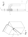
Figure 1 is a perspective view of a straw applied to a beverage package; -
Figure 2 is an enlarged-scale view of the straw inFigure 1 ; -
Figure 3 is a schematic front view of a packer machine which bends and wraps the straw inFigure 1 ; -
Figures 4, 5 and 6 are three different enlarged-scale views of respective details of a bending drum of the packer machine inFigure 3 ; -
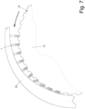
Figure 7 is a side view of a first orienting device of the bending drum inFigure 3 ; -
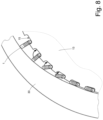
Figure 8 is an enlarged-scale view of a detail of the first orienting device inFigure 7 ; -
Figure 9 is a side view of a second orienting device of the bending drum inFigure 3 ; and -
Figure 10 is an enlarged-scale view of a detail of the second orienting device inFigure 9 . - In
Figure 1 , thenumeral 1 indicates, as a whole, a straw (made of paper or plastic) which is applied to the back of a beverage package. Thestraw 1 has a flat end 2 (which is grasped by the user's lips) and a pointed end 3 (to more effectively break through the cap sealing a dispensing opening of the package). - In addition, the
straw 1 has an intermediatecorrugated portion 4 at which thestraw 1 can be bent easily and without breakage (i.e., elastically) to take, in use, the shape most suitable for the user. - The
straw 1 is individually packaged (i.e., it has been inserted individually into itsown wrapping 5, not shown inFigure 1 and shown inFigure 2 ) after being bent into a "U" shape (i.e., by 180°) at the intermediate corrugated portion 4 (the purpose of the bending into a "U" shape is to reduce the overall size of thestraw 1 so that it remains within the dimensions of the back wall of the package to which thestraw 1 is applied). - In
Figure 3 , thenumeral 6 indicates, as a whole, a packer machine, which receives thestraight straws 1 from a manufacturing machine (not shown), corrugates thestraws 1, bends thestraws 1 into a "U" shape, and inserts thebent straws 1 intocorresponding wrappings 5. - The
packer machine 6 comprises ahopper 7, which is suitable for containing a mass ofstraight straws 1 coming from the manufacturing machine and moving progressively by gravity downwards, that is to say to the bottom of thehopper 7. As an alternative to thehopper 7, thepacker machine 6 could have any buffer or collector for a mass of straws. - As a further alternative, the
packer machine 6 could receive the straws in an orderly manner (i.e., not collected in a mass), for example directly from the manufacturing machine. - At the bottom of the
hopper 7 there is aretrieval conveyor 8 which, in an input station S1, retrieves a succession ofstraight straws 1 and moves them transversely (i.e., perpendicular to a longitudinal axis of the straws 1). According to a preferred embodiment shown in the attached figures, theretrieval conveyor 8 consists of a drum, which is mounted so that it can rotate around a rotation axis 9 (horizontal and perpendicular to the plane inFigure 3 ) and has a plurality of suction seats, each designed to house a correspondingstraight straw 1. According to a different embodiment, not shown, theretrieval conveyor 8 is a conveyor belt, i.e., it comprises a flexible belt, which is closed like a ring around two end pulleys and supports a plurality of suction seats, each designed to house a correspondingstraight straw 1. - The
packer machine 6 comprises acorrugator drum 10, which is mounted so that it can rotate around a rotation axis 11 (parallel to the rotation axis 9), has a plurality of seats, each designed to house a correspondingstraight straw 1, and receives thestraight straws 1 directly from theretrieval conveyor 8 in a transfer station S2. Along the periphery of thecorrugator drum 10 there is acorrugator device 12, which corrugates thestraight straws 1, i.e., it creates the intermediatecorrugated portion 4 in eachstraight straw 1. - In accordance with one embodiment, not shown, the
packer machine 6 could receivestraight straws 1 that are already corrugated; in this case, thepacker machine 6 does not include thecorrugator drum 10. - The
packer machine 6 comprises abending drum 13, which is mounted so that it can rotate around a rotation axis 14 (parallel to the rotation axis 11), has a plurality of suction seats 15 (shown more clearly inFigures 4-9 ), each designed to house a corresponding initiallystraight straw 1, and receives thestraight straws 1 directly from thecorrugator drum 10 in a transfer station S3. Bendingelements 16 are arranged in a fixed position (i.e., integral with a frame of thepacker machine 6 and therefore unmovable) around therotation axis 14, the former being coupled to thebending drum 13 and interacting with thestraws 1 carried by the suction seats to bend thestraws 1 into a "U" shape. - The
packer machine 6 comprises awaste drum 17, which is mounted so that it can rotate around a rotation axis 18 (parallel to the rotation axis 14), has a plurality of seats, each designed to house acorresponding U-bent straw 1, receives thestraws 1 directly from thebending drum 13 in a transfer station S4, and delivers thebent straws 1 in a transfer station S5 arranged downstream of the transfer station S4 in relation to the rotational direction of thewaste drum 17. - The
packer machine 6 comprises awrapping drum 19, which is mounted so that it can rotate around a rotation axis 20 (parallel to the rotation axis 18), has a plurality of suction seats, each designed to house a portion of a continuous (i.e., seamless)band 21 of wrapping material, and aU-bent straw 1. Each suction seat of the wrappingdrum 19 receives, in a feeding station S6, a portion of thecontinuous band 21 of wrapping material which is bent into a "U" shape inside the suction seat to define a pocket and then receives, directly from thewaste drum 17 in the transfer station S5, a bent straw 1 (which places itself inside the pocket previously formed in the suction seat). The wrappingdrum 22 is coupled to anapplicator drum 22, which is mounted so that it can rotate around a rotation axis 23 (parallel to the rotation axis 20) and applies (typically by heat-sealing) to thecontinuous band 21 of wrapping material and in a feeding station S7 acontinuous band 24 of wrapping material which closes the pockets containing thebent straws 1. Therefore, a continuous (i.e., seamless) succession of pockets, each containing abent straw 1, is fed from the wrappingdrum 22; this continuous succession of pockets, each containing abent straw 1, in jargon is called a "cartridge belt". - The
packer machine 6 comprises anoutput conveyor 25, which receives the "cartridge belt" (that is, it receives a continuous band ofwrappings 5 containing respective bent straws 1) from thewrapping drum 19 and moves the "cartridge belt" to an output of thepacker machine 6. - Preferably, the
whole packer machine 6 operates with a law of continuous motion, that is, with movements at a normally constant speed (when the productivity of thepacker machine 6 is stable or in steady, and therefore non-transient, state). - The
packer machine 6 operates on a dual line, that is to say it processes twostraws 1 at a time, arranged head first, side by side (that is, axially aligned with each other). In other words, theretrieval conveyor 8 has a set of pairs of suction seats (axially aligned with each other) to retrieve twostraight straws 1 at a time from the output mouth of thehopper 7, thecorrugator drum 10 has a set of pairs of seats (axially aligned with each other), which simultaneously receive twostraight straws 1 from theretrieval conveyor 8, simultaneously corrugate twostraws 1 together with thecorrugator device 12, and simultaneously deliver twostraight straws 1 to thebending drum 13. In turn, thebending drum 13 has a set of pairs of suction seats 15 (axially aligned with each other or side-by-side and aligned along a direction perpendicular to a moving direction of the bending drum 13), which simultaneously receive twostraight straws 1 from thecorrugator drum 10, simultaneously bend twostraws 1, and simultaneously deliver twobent straws 1 to thewaste drum 17. In turn, thewaste drum 17 has a set of pairs of seats (axially aligned with each other), which simultaneously receive twobent straws 1 from thebending drum 13 and simultaneously deliver twobent straws 1 to the wrappingdrum 19. In turn, the wrappingdrum 19 has a set of pairs of suction seats (axially aligned with each other), which simultaneously receive twobent straws 1 from thewaste drum 17, simultaneously create two wrappings 5 (operating with twocontinuous bands wrappings 5 to theoutput conveyor 25. In turn, theoutput conveyor 25 has a set of pairs of suction seats (axially aligned with each other), which simultaneously receive two wrappings 5 (and thus two "cartridge belts") from the wrappingdrum 19. - According to a preferred, non-limiting embodiment, the
hopper 7 containsstraight straws 1 of double length (i.e., twice the length of astraw 1 coming out of the packer machine 6), which are cut in half by acutting device 26 coupled to theretrieval conveyor 8. - As shown in
Figures 4, 5 and 6 , thebending drum 14 has two sets ofseats 15 arranged side by side: one set ofseats 15 is arranged on the right-hand side and the other set ofseats 15 is arranged on the left-hand side. That is, thebending drum 13 is provided with a plurality of pairs ofseats 15 that are side-by-side and aligned axially (i.e., perpendicular to the moving direction of the bending drum 13). In the transfer station S3, eachseat 15 contains arespective straw 1 which is still completely straight (as shown inFigure 4 ). Between the transfer station S3 and the transfer station S4, eachseat 15 contains a respective straw, which has been bent by 180° byrespective bending elements 16 and still has the bent portion (i.e., the "short" portion) protruding radially cantilevered (as shown inFigure 5 ). In the transfer station S4, eachseat 15 contains arespective straw 1, which has been bent by 180° by a bendingelement 16 and then rotated by 90° by an orientation system 27 (shown inFigures 7-10 ) to also arrange the bent portion (i.e., the "short" portion) inside theseat 15. - As shown in
Figure 6 , the orientation system 27 rotates by 90° thestraws 1 of one set ofseats 15 in one direction and rotates by 90° thestraws 1 of the other set ofseats 15 in an opposite direction; that is, if thestraws 1 of one set ofseats 15 are rotated by 90° clockwise, then thestraws 1 of the other set ofseats 15 are rotated by 90° anticlockwise. In this way, thestraws 1 located in the set ofseats 15 on the right have an orientation symmetrically opposite to thestraws 1 located in the set ofseats 15 on the left. This seeming unevenness, instead, makes it possible to form two "cartridge belts" that are perfectly identical, that is to say, completely indistinguishable from one another. - As shown in
Figures 7-10 , the orientation system 27 comprises two different orienting devices 28 and 29, each arranged on a respective side of the bendingdrum 13 and operating with a respective set ofseats 15; that is, the orienting device 28 is arranged on the left side of the bendingdrum 13 and operates with the set ofseats 15 on the left side, and the orienting device 29 is arranged on the right side of the bendingdrum 13 and operates with the set ofseats 15 on the right side. The orienting devices 28 and 29 are configured to rotate therespective straws 1 in opposite directions. - As shown in
Figures 7 and8 , the orienting device 28 is completely passive (i.e., it has no moving parts) and comprises a fixed orienting element 30 (i.e., which is rigidly fixed to a frame of thepacker machine 6 and does not rotate with the bending drum 13), which has an arc-of-a-circle shape, is arranged around part of the periphery of the bendingdrum 13, and has a variable distance from the bending drum 13 (in particular a distance decreasing along the rotational direction of the bending drum 13), so as to progressively force abent straw 1, located in arespective seat 15, to completely enter theseat 15 by rotating by 90° in a direction contrary to the rotational direction of the bendingdrum 13. In other words, the orienting device 28 rotates thebent straws 1 by 90° in a direction contrary to the rotational direction of the bendingdrum 13, and this type of rotation can be obtained by using the movement of the bendingdrum 13 by making thestraws 13 enter in contact with a "fixed obstacle" (the orienting element 30). - According to a possible embodiment, the orienting
element 30 can be integrated, i.e., form a single, seamless body, with arespective bending element 16. - As shown in
Figures 9 and10 , the orienting device 29 is partially active (i.e., it has moving parts) and comprises an orientingbelt 31, which is closed like a ring around twopulleys drum 13, and has anactive branch 34 facing the periphery of the bendingdrum 13. Theactive branch 34 of the orientingbelt 31 has a variable distance from the bending drum 13 (in particular a distance decreasing along the rotational direction of the bending drum 13) and, in use, moves in the same rotational direction as the bendingdrum 13 at a higher speed than the peripheral speed of theseats 15 of the bendingdrum 13, so as to progressively force abent straw 1, located in arespective seat 15, to completely enter theseat 15 by rotating by 90° in the same rotational direction as the bendingdrum 13. In other words, the orienting device 29 rotates the bent straws by 90° in the same rotational direction as the bendingdrum 13, and this type of rotation can only be achieved by "accelerating" the bent straws 1 (through theactive branch 33 of the orienting belt 31) relative to the rotation of the bendingdrum 13. - According to a preferred embodiment, the
pulley 32 is idle whereas thepulley 33 is motorized and receives the motion from the same motor such that it causes the rotation of the bendingdrum 13, so that the moving speed of the orientingbelt 31 always corresponds to the peripheral speed of theseats 15 of the bendingdrum 13, to prevent both rotating thebent straws 1 by less than 90° (if the moving speed of the orientingbelt 31 is too slow) and rotating thebent straws 1 too fast, subjecting thebent straws 1 to excessive mechanical stress 1 (if the moving speed of the orientingbelt 31 is too fast). - According to a preferred embodiment, the two
pulleys drum 13 so as to allow the orientingbelt 31 to gain a variable distance from the bending drum 13 (in particular a distance decreasing along the rotational direction of the bending drum 13); in particular, thepulley 32 arranged upstream relative to the rotational direction of the bendingdrum 13 is farther from the periphery of the bendingdrum 13, whereas thepulley 33 arranged downstream relative to the rotational direction of the bendingdrum 13 is closer to the periphery of the bendingdrum 13. - According to a preferred embodiment, the orienting device 29 also comprises a fixed accompanying element 35 (i.e., which is rigidly fixed to a frame of the
packer machine 6 and does not rotate with the bending drum 13), which has an arc-of-a-circle shape, is arranged around part of the periphery of the bendingdrum 13, and is arranged upstream of the orientingbelt 31 relative to the rotational direction of the bendingdrum 13 to contain thestraws 1 inside theseats 15 before the action of the orientingbelt 31. Similarly, according to a preferred embodiment, the orienting device 29 also comprises a fixed accompanying element 36 (i.e., which is rigidly fixed to a frame of thepacker machine 6 and does not rotate with the bending drum 13), which has an arc-of-a-circle shape, is arranged around part of the periphery of the bendingdrum 13, and is arranged downstream of the orientingbelt 31 relative to the rotational direction of the bendingdrum 13 to contain thestraws 1 inside theseats 15 after the action of the orientingbelt 31. - According to a possible embodiment, the accompanying
element 35 can be integrated, i.e., form a single, seamless body, with arespective bending element 16. - The orienting device 29 comprises an orienting conveyor having the
active branch 34 which has a variable distance from the bendingdrum 13 and, in use, moves in the same direction as the moving direction of the bendingdrum 13 at a higher speed than a speed of theseats 15. In the embodiment shown in the attached figures, the orienting conveyor comprises the orientingbelt 31, which is closed like a ring around the twopulleys active branch 34; according to a different embodiment, not shown, the orienting conveyor comprises a cylindrical roller (or a succession of cylindrical rollers) having theactive branch 34. - The embodiments described herein may be combined with each other without departing from the scope of protection of the present invention.
- The
packer machine 6 described above has many advantages. - Firstly, the
packer machine 6 described above makes it possible to form two "cartridge belts" that are perfectly identical, that is to say, completely indistinguishable from one another, and this simplifies the subsequent processing steps, since an automatic machine (for example, a filling machine for the production of single-dose beverage parallelepiped packages) using thestraws 1 can operate with only one type of "cartridge belt". - In addition, the changes made to the
packer machine 6 described above have no negative impact on productivity and quality as they do not introduce new operations on thestraws 1 but merely reverse the rotational direction of a part of thebent straws 1 immediately after the 180° bending operation. - Lastly, the
packer machine 6 described above requires minimal changes compared to an existing packer machine and is therefore simple, inexpensive and compact to manufacture. -
- 1
- straw
- 2
- flat end
- 3
- pointed end
- 4
- intermediate portion
- 5
- wrapping
- 6
- packer machine
- 7
- hopper
- 8
- retrieval conveyor
- 9
- rotation axis
- 10
- corrugator drum
- 11
- rotation axis
- 12
- corrugator device
- 13
- bending drum
- 14
- rotation axis
- 15
- seats
- 16
- bending elements
- 17
- waste drum
- 18
- rotation axis
- 19
- wrapping drum
- 20
- rotation axis
- 21
- continuous band of wrapping material
- 22
- applicator drum
- 23
- rotation axis
- 24
- continuous band of wrapping material
- 25
- output conveyor
- 26
- cutting device
- 27
- orientation system
- 28
- orienting device
- 29
- orienting device
- 30
- orienting element
- 31
- orienting belt
- 32
- idler pulley
- 33
- motorized pulley
- 34
- active branch
- 35
- accompanying element
- 36
- accompanying element
- S1
- input station
- S2
- transfer station
- S3
- transfer station
- S4
- transfer station
- S5
- transfer station
- S6
- feeding station
- S7
- feeding station
Claims (15)
- A wrapping method for straws (1) comprising the steps of:moving, by means of a bending conveyor (13), two seats (15), which are arranged beside one another;inserting, in a first transfer station (S3), two straight straws (1) into the two seats (15);bending, by means of at least one bending element (16), an outer portion of each straw (1) carried by a respective seat (15) by 180° relative to the rest of the straw (1);rotating, by means of an orientation system (27), each bent straw (1) relative to the bending conveyor (13) in order to also insert the outer portion of the bent straw (1) into the corresponding seat (15); andretrieving, in a second transfer station (S4), the two bent straws (1) from the two seats (15);the wrapping method is characterized in that a first bent straw (1) is rotated in a first direction and a second bent straw (1) is rotated in a second direction contrary to the first direction.
- The wrapping method according to claim 1, wherein the first bent straw (1) is rotated by 90° in the first direction and the second bent straw (1) is rotated by 90° in the second direction contrary to the first direction.
- The wrapping method according to claim 1 or 2, wherein the first direction is the same as a moving direction of the bending conveyor (13) and the second direction is contrary to the moving direction of the conveyor (13).
- The wrapping method according to claim 1, 2 or 3, wherein the orientation system (27) comprises two different orienting devices (28, 29), each arranged on a respective side of the bending conveyor (13) and operating with a respective seat (15).
- The wrapping method according to claim 4, wherein the first orienting device (28) comprises a fixed orienting element (30), which has a variable distance from the bending conveyor (13), in particular a distance decreasing along a moving direction of the bending conveyor (13), so as to progressively force the first straw (1) to completely enter the first seat (15) by rotating in the first direction contrary to the moving direction of the bending conveyor (13).
- The wrapping method according to claim 4 or 5, wherein the second orienting device (29) comprises an orienting conveyor having an active branch (34), which has a variable distance from the bending conveyor (13), in particular a distance decreasing along a moving direction of the bending conveyor (13), and, in use, moves in a same direction as the moving direction of the bending conveyor (13) and at a higher speed than a speed of the second seat (15), so as to progressively force the second straw (1) to completely enter the second seat (15) by rotating in the second direction contrary to the moving direction of the bending conveyor (13).
- The wrapping method according to claim 6, wherein the orienting conveyor comprises an orienting belt (31), which is closed like a ring around two pulleys (32, 33) and has the active branch (34), which has a variable distance from the bending conveyor (13) and, in use, moves in a same direction as the moving direction of the bending conveyor (13) and at a higher speed than a speed of the second seat (15), so as to progressively force the second straw (1) to completely enter the second seat (15) by rotating in the second direction contrary to the moving direction of the bending conveyor (13).
- The wrapping method according to claim 7, wherein a pulley (33) is motorized and receives the motion from the same motor that causes the rotation of the bending conveyor (13).
- The wrapping method according to claim 7 or 8, wherein the two pulleys (32, 33) are arranged at different distances from the bending conveyor (13) so as to allow the orienting belt (31) to gain a variable distance from the bending conveyor (13).
- The wrapping method according to claim 9, wherein a pulley (32) arranged upstream relative to the moving direction of the bending conveyor (13) is farther from the bending conveyor (13), whereas a pulley (33) arranged downstream relative to the moving direction of the bending conveyor (13) is closer to the bending conveyor (13).
- The wrapping method according to one of the claims from 7 to 10, wherein the bending conveyor (13) comprises:a first fixed accompanying element (35) upstream of the orienting belt (31) relative to the moving direction of the bending conveyor (13) to contain the second straw (1) inside the second seat (15) before the action of the orienting belt (31); anda second fixed accompanying element (36) arranged downstream of the orienting belt (31) relative to the moving direction of the bending conveyor (13) to contain the second straw (1) inside the second seat (15) after the action of the orienting belt (31).
- The wrapping method according to one of the claims from 1 to 11, wherein the bending conveyor (13) rotates around a rotation axis (14).
- The wrapping method according to one of the claims from 1 to 12, wherein the two seats (15) are beside one another and are aligned along a direction perpendicular to a moving direction of the bending conveyor (13).
- The wrapping method according to one of the claims from 1 to 13 and comprising the further step of creating a wrap (5) around each straw (1).
- A packer machine (6) for straws (1) comprising:a bending conveyor (13) configured to move two seats (15) beside one another;a first transfer station (S3) configured to insert two straight straws (1) into the two seats (15);at least one bending element (16) configured to bend an outer portion of each straw (1) carried by a respective seat (15) by 180° relative to the rest of the straw;an orientation system (27) configured to rotate each bent straw (1) relative to the bending conveyor (13) so as to also insert the outer portion of the bent straw (1) into the corresponding seat (15); anda second transfer station (S4) configured to retrieve the two bent straws (1) from the two seats (15);the packer machine (6) is characterized in that a first bent straw (1) is rotated in a first direction and a second bent straw (1) is rotated in a second direction contrary to the first direction.
Applications Claiming Priority (1)
| Application Number | Priority Date | Filing Date | Title |
|---|---|---|---|
| IT102023000003678A IT202300003678A1 (en) | 2023-03-01 | 2023-03-01 | WRAPPING METHOD AND STRAW PACKING MACHINE, WITH ORIENTATION BEFORE PACKING |
Publications (1)
| Publication Number | Publication Date |
|---|---|
| EP4458698A1 true EP4458698A1 (en) | 2024-11-06 |
Family
ID=86329756
Family Applications (1)
| Application Number | Title | Priority Date | Filing Date |
|---|---|---|---|
| EP24160230.9A Pending EP4458698A1 (en) | 2023-03-01 | 2024-02-28 | Wrapping method and packer machine for straws, with orientation before the packing |
Country Status (2)
| Country | Link |
|---|---|
| EP (1) | EP4458698A1 (en) |
| IT (1) | IT202300003678A1 (en) |
Citations (2)
| Publication number | Priority date | Publication date | Assignee | Title |
|---|---|---|---|---|
| WO2021250715A1 (en) | 2020-06-10 | 2021-12-16 | I.M.A. Industria Macchine Automatiche S.P.A. | Machine and method for the automated production of straws |
| CN115429086A (en) * | 2022-08-18 | 2022-12-06 | 浙江金申机械制造有限公司 | Method for manufacturing straw |
-
2023
- 2023-03-01 IT IT102023000003678A patent/IT202300003678A1/en unknown
-
2024
- 2024-02-28 EP EP24160230.9A patent/EP4458698A1/en active Pending
Patent Citations (2)
| Publication number | Priority date | Publication date | Assignee | Title |
|---|---|---|---|---|
| WO2021250715A1 (en) | 2020-06-10 | 2021-12-16 | I.M.A. Industria Macchine Automatiche S.P.A. | Machine and method for the automated production of straws |
| CN115429086A (en) * | 2022-08-18 | 2022-12-06 | 浙江金申机械制造有限公司 | Method for manufacturing straw |
Also Published As
| Publication number | Publication date |
|---|---|
| IT202300003678A1 (en) | 2024-09-01 |
Similar Documents
| Publication | Publication Date | Title |
|---|---|---|
| CN1211252C (en) | Packaging material folding device for packaging machines | |
| US3933239A (en) | Capsule positioning machine | |
| EP4240573B1 (en) | Method and unit to bend a straw | |
| JP2003516279A (en) | Equipment for filling blister bands with products | |
| GB2206327A (en) | A method of manufacturing packs of cigarettes with a hermetically-sealed wrapper | |
| GB2227221A (en) | A package structure for storing articles and a method and apparatus for accomplishing same. | |
| US4918901A (en) | Device for the infeed of discrete strips of tin foil in cigarette packaging machinery | |
| US5996309A (en) | Packaging machine with a rotary folding unit for manufacturing (soft) pouch-type packets for cigarettes | |
| EP4164874A1 (en) | Machine and method for the automated production of straws | |
| EP2334578B1 (en) | A product conveyor unit | |
| ITGE930026A1 (en) | DEVICE TO TRANSFORM A RANDOM SUCCESSION OF UNIT PACKAGES INTO AN ORDINATED SUCCESSION, UNIFORM OF THE SAME. | |
| JP2010280428A (en) | Conveying device for outer bag packaging machine and outer bag packaging machine provided with the device | |
| EP3222532B1 (en) | Orientation unit and method for causing a change in orientation of a parallelepiped-shaped article in a packing machine | |
| CN218477734U (en) | Cigarette packet packing line with split double-layer cartons | |
| JPH02269611A (en) | Cigarette packing machine | |
| EP0792807B1 (en) | Method and unit for folding packing blanks along preformed bend lines | |
| EP2065308B1 (en) | Method for processing the edges of a soft package | |
| EP3070005B1 (en) | Wrapping method and packer machine to manufacture packets of tobacco articles, each containing two distinct groups of tobacco articles | |
| EP4059849B1 (en) | Packing method and unit to pack articles, in particular straws, with automatic rejection of defective articles | |
| EP4458697A1 (en) | Method and machine for wrapping straws | |
| EP3702291A1 (en) | Transfer drum to transfer objects along a circular path and adjustment method to carry out a format change of the transfer drum | |
| GB2063811A (en) | Packing of cigarettes | |
| EP4455032A2 (en) | Straw processing method and machine | |
| JP2007099508A (en) | Transfer method and unit for product in packing device operating intermittently | |
| IT202300003678A1 (en) | WRAPPING METHOD AND STRAW PACKING MACHINE, WITH ORIENTATION BEFORE PACKING |
Legal Events
| Date | Code | Title | Description |
|---|---|---|---|
| PUAI | Public reference made under article 153(3) epc to a published international application that has entered the european phase |
Free format text: ORIGINAL CODE: 0009012 |
|
| STAA | Information on the status of an ep patent application or granted ep patent |
Free format text: STATUS: THE APPLICATION HAS BEEN PUBLISHED |
|
| AK | Designated contracting states |
Kind code of ref document: A1 Designated state(s): AL AT BE BG CH CY CZ DE DK EE ES FI FR GB GR HR HU IE IS IT LI LT LU LV MC ME MK MT NL NO PL PT RO RS SE SI SK SM TR |
|
| STAA | Information on the status of an ep patent application or granted ep patent |
Free format text: STATUS: REQUEST FOR EXAMINATION WAS MADE |
|
| 17P | Request for examination filed |
Effective date: 20250502 |