EP4458671A1 - Ejecting energy module from an aircraft - Google Patents
Ejecting energy module from an aircraft Download PDFInfo
- Publication number
- EP4458671A1 EP4458671A1 EP24173949.9A EP24173949A EP4458671A1 EP 4458671 A1 EP4458671 A1 EP 4458671A1 EP 24173949 A EP24173949 A EP 24173949A EP 4458671 A1 EP4458671 A1 EP 4458671A1
- Authority
- EP
- European Patent Office
- Prior art keywords
- aircraft
- energy module
- ejection
- airframe
- internal compartment
- Prior art date
- Legal status (The legal status is an assumption and is not a legal conclusion. Google has not performed a legal analysis and makes no representation as to the accuracy of the status listed.)
- Pending
Links
Images





Classifications
-
- B—PERFORMING OPERATIONS; TRANSPORTING
- B64—AIRCRAFT; AVIATION; COSMONAUTICS
- B64D—EQUIPMENT FOR FITTING IN OR TO AIRCRAFT; FLIGHT SUITS; PARACHUTES; ARRANGEMENT OR MOUNTING OF POWER PLANTS OR PROPULSION TRANSMISSIONS IN AIRCRAFT
- B64D37/00—Arrangements in connection with fuel supply for power plant
- B64D37/02—Tanks
- B64D37/06—Constructional adaptations thereof
- B64D37/12—Constructional adaptations thereof jettisonable
-
- B—PERFORMING OPERATIONS; TRANSPORTING
- B64—AIRCRAFT; AVIATION; COSMONAUTICS
- B64D—EQUIPMENT FOR FITTING IN OR TO AIRCRAFT; FLIGHT SUITS; PARACHUTES; ARRANGEMENT OR MOUNTING OF POWER PLANTS OR PROPULSION TRANSMISSIONS IN AIRCRAFT
- B64D1/00—Dropping, ejecting, releasing or receiving articles, liquids, or the like, in flight
- B64D1/02—Dropping, ejecting, or releasing articles
-
- B—PERFORMING OPERATIONS; TRANSPORTING
- B64—AIRCRAFT; AVIATION; COSMONAUTICS
- B64D—EQUIPMENT FOR FITTING IN OR TO AIRCRAFT; FLIGHT SUITS; PARACHUTES; ARRANGEMENT OR MOUNTING OF POWER PLANTS OR PROPULSION TRANSMISSIONS IN AIRCRAFT
- B64D37/00—Arrangements in connection with fuel supply for power plant
- B64D37/02—Tanks
-
- B—PERFORMING OPERATIONS; TRANSPORTING
- B64—AIRCRAFT; AVIATION; COSMONAUTICS
- B64D—EQUIPMENT FOR FITTING IN OR TO AIRCRAFT; FLIGHT SUITS; PARACHUTES; ARRANGEMENT OR MOUNTING OF POWER PLANTS OR PROPULSION TRANSMISSIONS IN AIRCRAFT
- B64D27/00—Arrangement or mounting of power plants in aircraft; Aircraft characterised by the type or position of power plants
- B64D27/02—Aircraft characterised by the type or position of power plants
- B64D27/30—Aircraft characterised by electric power plants
- B64D27/35—Arrangements for on-board electric energy production, distribution, recovery or storage
- B64D27/355—Arrangements for on-board electric energy production, distribution, recovery or storage using fuel cells
-
- B—PERFORMING OPERATIONS; TRANSPORTING
- B64—AIRCRAFT; AVIATION; COSMONAUTICS
- B64D—EQUIPMENT FOR FITTING IN OR TO AIRCRAFT; FLIGHT SUITS; PARACHUTES; ARRANGEMENT OR MOUNTING OF POWER PLANTS OR PROPULSION TRANSMISSIONS IN AIRCRAFT
- B64D27/00—Arrangement or mounting of power plants in aircraft; Aircraft characterised by the type or position of power plants
- B64D27/02—Aircraft characterised by the type or position of power plants
- B64D27/30—Aircraft characterised by electric power plants
- B64D27/35—Arrangements for on-board electric energy production, distribution, recovery or storage
- B64D27/357—Arrangements for on-board electric energy production, distribution, recovery or storage using batteries
Definitions
- This invention relates generally to an aircraft and, more particularly, to preparing an energy source for an emergency.
- an aircraft system includes an aircraft airframe, a drive unit, a mechanical load, an energy module and an ejection system.
- the aircraft airframe has an internal compartment.
- the drive unit is mounted with the aircraft airframe.
- the mechanical load includes a mechanical load rotor.
- the drive unit is coupled to and configured to drive rotation of the mechanical load rotor.
- the energy module is disposed within the internal compartment.
- the energy module includes an energy source configured to power or fuel operation of the drive unit.
- the ejection system is configured to eject the energy module out of the internal compartment and away from the aircraft airframe.
- another aircraft system includes an aircraft airframe, a drive unit, a mechanical load, a power module and an ejection system.
- the drive unit is mounted with the aircraft airframe.
- the mechanical load includes a mechanical load rotor.
- the drive unit is coupled to and configured to drive rotation of the mechanical load rotor.
- the power module is arranged with the aircraft airframe.
- the power module includes a power source configured to power operation of the drive unit.
- the ejection system is configured to eject the power module away from the aircraft airframe.
- another aircraft system includes an aircraft airframe, a drive unit, a mechanical load, an energy module and an ejection system.
- the drive unit is mounted with the aircraft airframe.
- the mechanical load includes a mechanical load rotor.
- the drive unit is coupled to and configured to drive rotation of the mechanical load rotor.
- the energy module is arranged with the aircraft airframe.
- the energy module includes an energy source and a housing.
- the energy source is configured to power or fuel operation of the drive unit.
- the housing is configured to contain and seal off the energy source from an external environment during or after ejection of the energy module away from the aircraft airframe.
- the ejection system is configured to eject the energy module away from the aircraft airframe.
- the power module may be coupled to the drive unit by a line.
- the ejection system may be configured to sever the line prior to or during ejection of the power module away from the aircraft airframe.
- the energy source may be fluidly coupled to the drive unit by a fluid line.
- the ejection system may be configured to sever the fluid line prior to or during ejection of the energy module out of the internal compartment.
- the energy source may include a fuel reservoir configured to contain a fluid fuel.
- the fluid line may be a fuel line.
- the fluid line may be configured to transfer a heat exchange working fluid between the energy source and the drive unit.
- the energy source may be electrically coupled to the drive unit by an electric line.
- the ejection system may be configured to sever the electric line prior to or during ejection of the energy module out of the internal compartment.
- the aircraft airframe may include a wall, a cover and an opening through the wall to the internal compartment.
- the cover may be configured to close the opening.
- the ejection system may be configured to move the cover and open the opening to facilitate ejection of the energy module out of the internal compartment through the opening.
- the aircraft airframe may include a wall adjacent the internal compartment.
- the ejection system may be configured to form an opening through the wall to facilitate ejection of the energy module out of the internal compartment through the opening.
- the ejection system may include a propulsion device configured to propel the energy module: out of the internal compartment; and/or away from the aircraft airframe.
- the aircraft system may also include a descent control device arranged with the energy module.
- the descent control device may be configured to control descent of the energy module following ejection away from the aircraft airframe.
- the energy module may also include a housing configured to contain and seal off the energy source from an external environment before, during or after ejection of the energy module out of the internal compartment and away from the aircraft airframe.
- the energy module may also include a tracking device which is activated during or after ejection of the energy module out of the internal compartment and away from the aircraft airframe.
- the airframe may include a fuselage.
- the internal compartment may be disposed in the fuselage.
- the airframe may include a wing.
- the internal compartment may be disposed in the wing.
- the airframe may include a nacelle for an aircraft propulsion system.
- the internal compartment may be disposed in the nacelle.
- the drive unit may be configured as or otherwise include an internal combustion engine.
- the internal combustion engine may include a rotating structure coupled to the mechanical load rotor.
- the drive unit may include a fluid turbine coupled to the mechanical load rotor.
- the drive unit may be configured as or otherwise include an electric motor.
- the mechanical load rotor may be configured as or otherwise include a thrust rotor.
- the mechanical load may be configured to generate aircraft thrust with the thrust rotor.
- the invention may include any one or more of the individual features disclosed above and/or below alone or in any combination thereof.
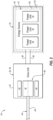
- FIG. 1 illustrates a system 20 for an aircraft 22; see also FIG. 3 .
- the aircraft 22 may be an airplane, a helicopter, a drone (e.g., an unmanned aerial vehicle (UAV)) or any other manned or unmanned aerial vehicle or unmanned aerial system.
- the aircraft system 20 includes an aircraft power system 24 and an aircraft airframe 26.
- the power system 24 may be configured as or otherwise include a propulsion system for the aircraft 22.
- the power system 24 may also or alternatively be configured as or otherwise include an electrical power system for the aircraft 22.
- the power system 24 of FIG. 1 includes a mechanical load 28, a drive unit 30 and an energy module 32.
- the mechanical load 28 of FIG. 1 includes at least one driven rotor 34 - a mechanical load rotor.
- This driven rotor 34 may be configured as a bladed thrust rotor for the aircraft propulsion system.
- This thrust rotor may be a propulsor rotor for generating propulsive (e.g., forward) thrust.
- the thrust rotor may also or alternatively be a lift rotor for generating lift thrust.
- the thrust rotor examples include, but are not limited to, a fan rotor for a ducted fan engine (e.g., a turbofan engine), a propeller rotor for a propeller engine (e.g., a turboprop engine), an open rotor for an open rotor engine (e.g., a pusher fan engine, an open tractor rotor engine, etc.), and a rotorcraft rotor (e.g., a main helicopter rotor) for a turboshaft engine.
- the driven rotor 34 may alternatively be configured as a generator rotor in an electric power generator for the electrical power system.
- the mechanical load 28 may be described below as a thrust section of the aircraft propulsion system and the driven rotor 34 may be described below as the thrust rotor.
- the drive unit 30 is configured to drive rotation of the driven rotor 34 and thereby power operation of the mechanical load 28.
- the drive unit 30 of FIG. 2 is configured as or otherwise includes an electric motor 36.
- This electric motor 36 is configured to convert electricity received from the energy module 32 into mechanical power.
- the mechanical power may be utilized for various purposes within the aircraft system 20 of FIG. 1 including driving rotation of the driven rotor 34.
- the electric motor 36 of FIG. 2 includes an electric motor rotor 38 and an (e.g., annular) electric motor stator 40, where the motor stator 40 may be radially outboard of and circumscribe the motor rotor 38.
- the electric motor 36 also includes an electric motor case 42 that at least partially or completely houses the motor rotor 38 and the motor stator 40.
- the drive unit 30 of the present disclosure is not limited to such an exemplary axial flux electric motor nor to electric motor applications.
- the electric motor 36 may alternatively be configured as a radial flux electric motor.
- the drive unit 30 may be configured as or otherwise include an internal combustion engine or a fluid turbine as described below in further detail (e.g., see FIGS. 11 and 12 ).
- the drive unit 30 is coupled to the driven rotor 34 through a drivetrain 44.
- This drivetrain 44 may be configured as a direct drive drivetrain, where a rotating structure 46 of the drive unit 30 (e.g., the motor rotor 38 of FIG. 2 ) is operable to rotate at a common (the same) rotational speed as the driven rotor 34.
- the drivetrain 44 may be configured as (or otherwise include) a driveshaft 48 which extends between and is connected to the rotating structure 46 and the driven rotor 34.
- the drivetrain 44 may be configured as a geared drivetrain where the rotating structure 46 is operable to rotate at a different (e.g., faster, or slower) rotational speed than the driven rotor 34.
- the drivetrain 44 may include a geartrain 50 (e.g., a transmission, an epicyclic geartrain, a gearbox, etc.) between and coupled to the rotating structure 46 and the driven rotor 34.
- the energy module 32 of FIG. 1 includes an energy source 52 and an energy module housing 54.
- the energy module 32 and its energy source 52 may be respectively configured as an electric power module and an electric power source.
- the energy source 52 of FIG. 2 includes one or more electric power units 56 arranged with (e.g., housed within, supported by, etc.) the module housing 54.
- Each of these electric power units 56 is configured to supply (e.g., output) electric power; e.g., electricity.
- One or more of the electric power units 56 may each be configured as or otherwise include a battery, a bank of batteries or another type of power storage device(s).
- one or more of the electric power units 56 may each be configured as or otherwise include a fuel cell or a stack of fuel cells.
- the energy source 52 and its electric power units 56 are electrically coupled to the drive unit 30 through one or more lines 58 (e.g., electric lines), where each line 58 projects out of the module housing 54 to the drive unit 30.
- the module housing 54 may be configured as an integral part of the energy source 52 and its one or more electric power units 56.
- the module housing 54 may be configured as a case containing and supporting internal components of the electric power unit(s) 56.
- the module housing 54 for example, may be configured as a battery case, a battery bank case, a fuel cell case or a fuel cell stack case.
- the energy source 52 may include one or more discrete energy source cases (see dashed line 60) for its electric power unit(s) 56, and the module housing 54 may house the energy source 52 and its case(s).
- the power system 24 and its power system members 28, 30 and 32 are arranged with and mounted to the aircraft airframe 26.
- the aircraft 22 is illustrated in FIG. 3 as an airplane.
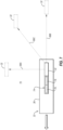
- the aircraft airframe 26 of FIG. 3 includes an aircraft fuselage 62, one or more aircraft wings 64 and one or more aircraft propulsion system nacelles 66.
- the mechanical load 28 and the drive unit 30 may be arranged with (e.g., housed within, mounted with, etc.) a respective one of the nacelles 66.
- the energy module 32 and its members may also be arranged with (e.g., housed within, mounted with, etc.) the respective nacelles 66.
- the energy module 32 may be remote from the mechanical load 28 and the drive unit 30.
- the energy module 32 may alternatively be arranged (e.g., housed within, mounted to, etc.) a respective one of the wings 64 or the fuselage 62. At any of these locations, the energy module 32 may be configured within / internal to the aircraft airframe 26.
- the energy module 32 of FIG. 4A for example, is disposed within an internal compartment 68 of the aircraft airframe 26 such that the energy module 32 and its energy source 52 are not exposed to an environment 70 external to the aircraft 22 and its aircraft airframe 26 during normal aircraft operation.
- FIG. 4A for example, is disposed within an internal compartment 68 of the aircraft airframe 26 such that the energy module 32 and its energy source 52 are not exposed to an environment 70 external to the aircraft 22 and its aircraft airframe 26 during normal aircraft operation.
- FIG. 4A for example, is disposed within an internal compartment 68 of the aircraft airframe 26 such that the energy module 32 and its energy source 52 are not exposed to an environment 70 external to the aircraft 22 and
- the module housing 54 may alternatively be configured to form an exterior portion of the aircraft airframe 26 (e.g., recessed into and partially form an exterior skin 72 of the aircraft airframe 26).
- the module housing 54 may be external to the aircraft airframe 26.
- the aircraft 22 may land or conduct an emergency landing at a location other than an airport (or may conduct an emergency landing at the airport).
- a pilot or pilots may conduct the emergency landing of the aircraft 22 in an open field or on a body of water.
- the pilot(s) may abandon the aircraft 22, such as in an ejection.
- the pilot(s) may eject from the aircraft 22.
- the pilot may guide the aircraft 22 as long as possible until contacting the ground.
- the aircraft 22 may be subject to relatively strong forces and stresses which can dislodge, break and/or otherwise damage various components of the aircraft 22.
- the aircraft system 20 of FIG. 1 is configured with an ejection system 74.
- This ejection system 74 is configured to eject the energy module 32 and its energy source 52 from the aircraft 22 and its aircraft airframe 26 prior to the emergency landing.
- the energy module 32 and its energy source 52 may not be subject to the same forces and/or stresses as the rest of the aircraft 22 and its airframe 26.
- the energy module 32 and its energy source 52 may be protected from potential dangerous situations, such as fire.
- the ejection system 74 of FIG. 1 includes one or more propulsion devices 76. These propulsion devices 76 are configured to propel the energy module 32 out of the internal compartment 68 (when applicable) and away from the aircraft airframe 26; e.g., see FIGS. 5A and 5B .
- Each propulsion device 76 of FIG. 6A is configured as a spring element 78; e.g., a coil spring, a leaf spring, etc. Prior to ejection, the spring element 78 is compressed between the energy module 32 and its module housing 54 and a fixed structure 80 of the aircraft airframe 26.
- the ejection system 74 see FIG.
- each propulsion device 76 of FIG. 6B is configured as a rocket 82.
- the ejection system 74 lights the rocket 82, and the lit rocket 82 propels the energy module 32 away from the aircraft airframe 26 (see FIG. 1 ).
- each propulsion device 76 of FIG. 6C is configured as a miniature jet engine 84. For ejection, the ejection system 74 (see FIG.
- the jet engine 84 turns on (e.g., powers, lights, etc.) the jet engine 84 and the jet engine 84 propels the energy module 32 away from the aircraft airframe 26 (see FIG. 1 ).
- the present disclosure is not limited to the foregoing exemplary propulsion device types or configurations.
- the ejection system 74 and its propulsion devices 76 may be configured to eject and propel the energy module 32 in various directions away from the aircraft 22 and its aircraft airframe 26.
- the energy module 32 may be ejected / propelled in an upward direction 86A away from the aircraft 22 and its aircraft airframe 26.
- the energy module 32 may be ejected / propelled in a lateral direction 86B away from the aircraft 22 and its aircraft airframe 26.
- the energy module 32 may be ejected / propelled in an upward-lateral direction 86C away from the aircraft 22 and its aircraft airframe 26.
- the lateral direction may be to a side of the aircraft 22 and its aircraft airframe 26 and/or to a rear of the aircraft 22 and its aircraft airframe 26. In general, however, the lateral direction (or component) does not extend towards a front of the aircraft 22 and its aircraft airframe 26 such that the energy module 32 does not become an obstacle to the still flying aircraft 22. Also in general, the energy module 32 is not ejected in a downward direction as this may propel the energy module 32 towards the ground at a higher velocity.
- the ejection system 74 may also be configured to provide an opening 88 through a wall 90 of the aircraft airframe 26.
- the energy module 32 may thereby be propelled through the opening 88 into the external environment 70 for ejection.
- the ejection system 74 of FIG. 5A is configured to trigger movement of a cover 92 for the opening 88.
- the cover 92 closes the opening 88 in the airframe wall 90.
- the ejection system 74 may trigger a cover actuator 94 to move the cover 92 to uncover the opening 88.
- the cover 92 may be a door that can translate (e.g., slide) or pivot open.
- the cover 92 may be a panel latched to the wall 90 via one or more latches.
- the actuator 94 may release the latches to facilitate separation of the cover 92 from the wall 90 and open the opening 88.
- the cover 92 may be a panel which can be separated (e.g., ejected) from the aircraft airframe 26.
- the ejection system 74 of FIG. 5B is configured as a controlled explosive charge 96. During an emergency, the ejection system 74 may trigger detonation of the explosive charge 96, and the detonated explosive charge 96 may explosively form the opening 88 in the airframe wall 90.
- the lines 58 coupling the energy source 52 to the drive unit 30 may be severed.
- this severing of the lines 58 may be a destructive severing.
- the ejection system 74 (or another device or system) may include a cutting device 98 (e.g., a shear) configured to cut each line 58.
- each line 58 may be configured to snap apart or pull out from the energy source 52 and/or the drive unit 30.
- a cutting device 98 e.g., a shear
- the severing of the lines 58 may be a nondestructive severing.
- Each line 58 of FIG. 8B includes at least one plug 100 which may be dislodged from a receptacle 102 when pulled by more than a certain (e.g., threshold) force; e.g., a force less than a force of ejection.
- a certain (e.g., threshold) force e.g., a force less than a force of ejection.
- the energy module 32 (and/or the wall 90) may be configured with a descent control device 104.
- This descent control device 104 is configured to deploy following ejection of the energy module 32 away from the aircraft 22 and its aircraft airframe 26 (see FIG. 7 ).
- the descent control device 104 is configured to control (e.g., slow) descent of the energy module 32 down through the external environment 70.
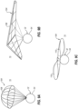
- the descent control device 104 may be configured as or otherwise include a parachute 106 attached to the energy module 32 and its module housing 54.
- FIG. 9A the descent control device 104 may be configured as or otherwise include a parachute 106 attached to the energy module 32 and its module housing 54.
- the descent control device 104 may be configured as or otherwise include a glider 108 attached to the energy module 32 and its module housing 54.
- the descent control device 104 may include a plurality of (e.g., helicopter) wings 110 attached to the energy module 32 and its module housing 54.
- the wings 110 may function similar to wings on a tree seed pod; e.g., a helicopter seed.
- the module housing 54 may be configured to close up and contain and seal off the energy source 52 from the external environment 70.
- an opening 112 through a sidewall 114 of the module housing 54 for the line(s) 58 may be covered by an actuatable door 116.
- this door 116 may also be configured as the shear for severing the respective line(s) 58.
- FIG. 10A an opening 112 through a sidewall 114 of the module housing 54 for the line(s) 58 may be covered by an actuatable door 116.
- this door 116 may also be configured as the shear for severing the respective line(s) 58.
- the module housing 54 may include multiple segments 118 (e.g., housing halves) which come together to enclose the energy source 52.
- the mating of the segments 118 may shear and thereby sever the respective line(s) 58.
- the module housing 54 may reduce or prevent exposure of the energy source 52 to the external environment 70 while falling to the ground as well as following a (e.g., controlled) impact with the ground.
- an interior of the module housing 54 may be lined with an impact absorption material 119.
- This impact absorption material 119 may be configured to absorb kinetic energy upon impact with the ground.
- Examples of the impact absorption material 119 include, but are not limited to, rubber, foam, corrugated metal or any other resilient, cellular and/or crushable material.
- the impact absorption material 119 may be disposed within the module housing 54 around the energy source 52, the impact absorption material 119 may also or alternatively line an exterior of the module housing 54.
- the energy module 32 may be configured with a tracking device 120; e.g., a global positioning system (GPS) tracker.
- This tracking device 120 may be activated just prior to, during or following the ejection of the energy module 32 from the aircraft airframe 26.
- personnel may be deployed to a location of the energy module 32 following ejection to quickly retrieve the energy module 32.
- the energy module 32 may also be provided with various labels to warn unauthorized personnel from tampering with the energy module 32.
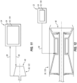
- the drive unit 30 may alternatively be configured as a fluid turbine 122.
- the energy source 52 may be configured as a fluid power source 124 that provides pressurized and/or heated working fluid (e.g., heat exchange fluid) to the fluid turbine 122 for expansion. The expansion of the working fluid in turn drives the rotation of the driven rotor 34 (see FIG. 1 ).
- the fluid power source 124 may be configured as part of a Rankin cycle system or may include a solid state heat source which heats the working fluid through a heat exchanger.
- each line 58 is configured as a fluid line for flowing the working fluid.
- the drive unit 30 may still alternatively be configured as an internal combustion engine 126.
- This engine 126 may be configured as a gas turbine engine, a rotary engine, a reciprocating piston engine or any other similar thermal engine.
- the energy source 52 may be configured as a fuel source 128 that provides fuel to the engine 126 for combustion.
- This fuel may be a non-hydrocarbon fuel / a hydrocarbon free fuel such as, but not limited to, hydrogen (H 2 ) fuel (e.g., H 2 gas) or ammonia (NH 3 ) fuel.
- the fuel may be a hydrocarbon fuel such as, but not limited to, kerosene, jet fuel or sustainable aviation fuel (SAF).
- the fuel source 128 may be configured as or otherwise include a fuel reservoir which contains the fuel provided to the engine 126.
- each line 58 is configured as a fuel line for flowing the fuel.
- the ejection system 74 may direct (e.g., pump) some or all of the fluid (e.g., other than fuel) out of the lines 58 and into the energy module 32.
- the fluid may be stored within the energy module 32 and its module housing 54 for ejection from the aircraft 22.
- the energy module 32 and its module housing 54 may prevent outside exposure to the fluid following impact with the ground.
Landscapes
- Engineering & Computer Science (AREA)
- Aviation & Aerospace Engineering (AREA)
- Transmission Devices (AREA)
Abstract
Description
- This invention relates generally to an aircraft and, more particularly, to preparing an energy source for an emergency.
- Various methods and systems are known in the art for preparing aircraft systems and components for an emergency. While these known preparation systems and methods have various benefits, there is still room in the art for improvement.
- According to an aspect of the invention, an aircraft system includes an aircraft airframe, a drive unit, a mechanical load, an energy module and an ejection system. The aircraft airframe has an internal compartment. The drive unit is mounted with the aircraft airframe. The mechanical load includes a mechanical load rotor. The drive unit is coupled to and configured to drive rotation of the mechanical load rotor. The energy module is disposed within the internal compartment. The energy module includes an energy source configured to power or fuel operation of the drive unit. The ejection system is configured to eject the energy module out of the internal compartment and away from the aircraft airframe.
- According to another aspect of the invention, another aircraft system includes an aircraft airframe, a drive unit, a mechanical load, a power module and an ejection system. The drive unit is mounted with the aircraft airframe. The mechanical load includes a mechanical load rotor. The drive unit is coupled to and configured to drive rotation of the mechanical load rotor. The power module is arranged with the aircraft airframe. The power module includes a power source configured to power operation of the drive unit. The ejection system is configured to eject the power module away from the aircraft airframe.
- According to still another aspect of the invention, another aircraft system includes an aircraft airframe, a drive unit, a mechanical load, an energy module and an ejection system. The drive unit is mounted with the aircraft airframe. The mechanical load includes a mechanical load rotor. The drive unit is coupled to and configured to drive rotation of the mechanical load rotor. The energy module is arranged with the aircraft airframe. The energy module includes an energy source and a housing. The energy source is configured to power or fuel operation of the drive unit. The housing is configured to contain and seal off the energy source from an external environment during or after ejection of the energy module away from the aircraft airframe. The ejection system is configured to eject the energy module away from the aircraft airframe.
- The following optional features may be applied individually, or in any combination, to any of the above aspects of the invention.
- The power module may be coupled to the drive unit by a line. The ejection system may be configured to sever the line prior to or during ejection of the power module away from the aircraft airframe.
- The energy source may be fluidly coupled to the drive unit by a fluid line. The ejection system may be configured to sever the fluid line prior to or during ejection of the energy module out of the internal compartment.
- The energy source may include a fuel reservoir configured to contain a fluid fuel. The fluid line may be a fuel line.
- The fluid line may be configured to transfer a heat exchange working fluid between the energy source and the drive unit.
- The energy source may be electrically coupled to the drive unit by an electric line. The ejection system may be configured to sever the electric line prior to or during ejection of the energy module out of the internal compartment.
- The aircraft airframe may include a wall, a cover and an opening through the wall to the internal compartment. The cover may be configured to close the opening. The ejection system may be configured to move the cover and open the opening to facilitate ejection of the energy module out of the internal compartment through the opening.
- The aircraft airframe may include a wall adjacent the internal compartment. The ejection system may be configured to form an opening through the wall to facilitate ejection of the energy module out of the internal compartment through the opening.
- The ejection system may include a propulsion device configured to propel the energy module: out of the internal compartment; and/or away from the aircraft airframe.
- The aircraft system may also include a descent control device arranged with the energy module. The descent control device may be configured to control descent of the energy module following ejection away from the aircraft airframe.
- The energy module may also include a housing configured to contain and seal off the energy source from an external environment before, during or after ejection of the energy module out of the internal compartment and away from the aircraft airframe.
- The energy module may also include a tracking device which is activated during or after ejection of the energy module out of the internal compartment and away from the aircraft airframe.
- The airframe may include a fuselage. The internal compartment may be disposed in the fuselage.
- The airframe may include a wing. The internal compartment may be disposed in the wing.
- The airframe may include a nacelle for an aircraft propulsion system. The internal compartment may be disposed in the nacelle.
- The drive unit may be configured as or otherwise include an internal combustion engine. The internal combustion engine may include a rotating structure coupled to the mechanical load rotor.
- The drive unit may include a fluid turbine coupled to the mechanical load rotor.
- The drive unit may be configured as or otherwise include an electric motor.
- The mechanical load rotor may be configured as or otherwise include a thrust rotor. The mechanical load may be configured to generate aircraft thrust with the thrust rotor.
- The invention may include any one or more of the individual features disclosed above and/or below alone or in any combination thereof.
- The foregoing features and the operation of the invention will become more apparent in light of the following description and the accompanying drawings.
-
-
FIG. 1 is a schematic illustration of a system for an aircraft. -
FIG. 2 is a schematic illustration of a drive unit coupled with an energy module. -
FIG. 3 is an illustration of the aircraft with components of the aircraft system schematically shown. -
FIGS. 4A-C are schematic illustrations of the energy module and an airframe of the aircraft in various arrangements. -
FIGS. 5A and 5B are schematic illustrations of various techniques for providing an opening through an airframe wall during ejection of the energy module. -
FIGS. 6A-C are schematic illustrations of the energy module with various propulsion devices for ejection. -
FIG. 7 is a schematic illustration of the aircraft with various trajectories for ejecting the energy module. -
FIGS. 8A and 8B are schematic illustrations of various techniques for decoupling the energy module from the drive unit. -
FIGS. 9A-C are illustrations of various descent control devices for the energy module deployed following ejection. -
FIGS. 10A and 10B are schematic illustrations of various techniques for enclosing and sealing off an energy source from an exterior environment. -
FIG. 11 is a schematic illustration of a fluid turbine coupled to the energy module. -
FIG. 12 is a schematic illustration of an engine coupled to the energy module. -
FIG. 1 illustrates asystem 20 for anaircraft 22; see alsoFIG. 3 . Theaircraft 22 may be an airplane, a helicopter, a drone (e.g., an unmanned aerial vehicle (UAV)) or any other manned or unmanned aerial vehicle or unmanned aerial system. Theaircraft system 20 includes anaircraft power system 24 and anaircraft airframe 26. Thepower system 24 may be configured as or otherwise include a propulsion system for theaircraft 22. Thepower system 24 may also or alternatively be configured as or otherwise include an electrical power system for theaircraft 22. Thepower system 24 ofFIG. 1 includes amechanical load 28, adrive unit 30 and anenergy module 32. - The
mechanical load 28 ofFIG. 1 includes at least one driven rotor 34 - a mechanical load rotor. This drivenrotor 34 may be configured as a bladed thrust rotor for the aircraft propulsion system. This thrust rotor may be a propulsor rotor for generating propulsive (e.g., forward) thrust. The thrust rotor may also or alternatively be a lift rotor for generating lift thrust. Examples of the thrust rotor include, but are not limited to, a fan rotor for a ducted fan engine (e.g., a turbofan engine), a propeller rotor for a propeller engine (e.g., a turboprop engine), an open rotor for an open rotor engine (e.g., a pusher fan engine, an open tractor rotor engine, etc.), and a rotorcraft rotor (e.g., a main helicopter rotor) for a turboshaft engine. The drivenrotor 34 may alternatively be configured as a generator rotor in an electric power generator for the electrical power system. However, for ease of description, themechanical load 28 may be described below as a thrust section of the aircraft propulsion system and the drivenrotor 34 may be described below as the thrust rotor. - The
drive unit 30 is configured to drive rotation of the drivenrotor 34 and thereby power operation of themechanical load 28. Thedrive unit 30 ofFIG. 2 , for example, is configured as or otherwise includes an electric motor 36. This electric motor 36 is configured to convert electricity received from theenergy module 32 into mechanical power. The mechanical power may be utilized for various purposes within theaircraft system 20 ofFIG. 1 including driving rotation of the drivenrotor 34. The electric motor 36 ofFIG. 2 includes anelectric motor rotor 38 and an (e.g., annular)electric motor stator 40, where themotor stator 40 may be radially outboard of and circumscribe themotor rotor 38. The electric motor 36 also includes anelectric motor case 42 that at least partially or completely houses themotor rotor 38 and themotor stator 40. Thedrive unit 30 of the present disclosure, however, is not limited to such an exemplary axial flux electric motor nor to electric motor applications. The electric motor 36, for example, may alternatively be configured as a radial flux electric motor. In another example, thedrive unit 30 may be configured as or otherwise include an internal combustion engine or a fluid turbine as described below in further detail (e.g., seeFIGS. 11 and 12 ). - Referring to
FIG. 1 , thedrive unit 30 is coupled to the drivenrotor 34 through adrivetrain 44. Thisdrivetrain 44 may be configured as a direct drive drivetrain, where a rotatingstructure 46 of the drive unit 30 (e.g., themotor rotor 38 ofFIG. 2 ) is operable to rotate at a common (the same) rotational speed as the drivenrotor 34. Thedrivetrain 44, for example, may be configured as (or otherwise include) adriveshaft 48 which extends between and is connected to the rotatingstructure 46 and the drivenrotor 34. Alternatively, thedrivetrain 44 may be configured as a geared drivetrain where the rotatingstructure 46 is operable to rotate at a different (e.g., faster, or slower) rotational speed than the drivenrotor 34. Thedrivetrain 44, for example, may include a geartrain 50 (e.g., a transmission, an epicyclic geartrain, a gearbox, etc.) between and coupled to the rotatingstructure 46 and the drivenrotor 34. - The
energy module 32 ofFIG. 1 includes anenergy source 52 and anenergy module housing 54. Referring toFIG. 2 , theenergy module 32 and itsenergy source 52 may be respectively configured as an electric power module and an electric power source. Theenergy source 52 ofFIG. 2 , for example, includes one or moreelectric power units 56 arranged with (e.g., housed within, supported by, etc.) themodule housing 54. Each of theseelectric power units 56 is configured to supply (e.g., output) electric power; e.g., electricity. One or more of theelectric power units 56, for example, may each be configured as or otherwise include a battery, a bank of batteries or another type of power storage device(s). In addition or alternatively, one or more of theelectric power units 56 may each be configured as or otherwise include a fuel cell or a stack of fuel cells. With such an arrangement, theenergy source 52 and itselectric power units 56 are electrically coupled to thedrive unit 30 through one or more lines 58 (e.g., electric lines), where eachline 58 projects out of themodule housing 54 to thedrive unit 30. - The
module housing 54 may be configured as an integral part of theenergy source 52 and its one or moreelectric power units 56. Themodule housing 54, for example, may be configured as a case containing and supporting internal components of the electric power unit(s) 56. Themodule housing 54, for example, may be configured as a battery case, a battery bank case, a fuel cell case or a fuel cell stack case. Alternatively, theenergy source 52 may include one or more discrete energy source cases (see dashed line 60) for its electric power unit(s) 56, and themodule housing 54 may house theenergy source 52 and its case(s). - Referring to
FIG. 1 , thepower system 24 and itspower system members aircraft airframe 26. For ease of description, theaircraft 22 is illustrated inFIG. 3 as an airplane. However, as discussed above, the present disclosure in not limited to such an exemplary aircraft. Theaircraft airframe 26 ofFIG. 3 includes anaircraft fuselage 62, one ormore aircraft wings 64 and one or more aircraft propulsion system nacelles 66. Themechanical load 28 and thedrive unit 30 may be arranged with (e.g., housed within, mounted with, etc.) a respective one of thenacelles 66. Theenergy module 32 and its members may also be arranged with (e.g., housed within, mounted with, etc.) therespective nacelles 66. Alternatively, theenergy module 32 may be remote from themechanical load 28 and thedrive unit 30. Theenergy module 32, for example, may alternatively be arranged (e.g., housed within, mounted to, etc.) a respective one of thewings 64 or thefuselage 62. At any of these locations, theenergy module 32 may be configured within / internal to theaircraft airframe 26. Theenergy module 32 ofFIG. 4A , for example, is disposed within aninternal compartment 68 of theaircraft airframe 26 such that theenergy module 32 and itsenergy source 52 are not exposed to anenvironment 70 external to theaircraft 22 and itsaircraft airframe 26 during normal aircraft operation. However, referring toFIG. 4B , it is contemplated themodule housing 54 may alternatively be configured to form an exterior portion of the aircraft airframe 26 (e.g., recessed into and partially form anexterior skin 72 of the aircraft airframe 26). Referring toFIG. 4C , it is also contemplated themodule housing 54 may be external to theaircraft airframe 26. - During an emergency situation and under certain conditions, the
aircraft 22 may land or conduct an emergency landing at a location other than an airport (or may conduct an emergency landing at the airport). A pilot or pilots, for example, may conduct the emergency landing of theaircraft 22 in an open field or on a body of water. Alternatively, the pilot(s) may abandon theaircraft 22, such as in an ejection. For example, in the case of a manned aircraft, the pilot(s) may eject from theaircraft 22. In the case of an unmanned aircraft, the pilot may guide theaircraft 22 as long as possible until contacting the ground. In any one of these situations, theaircraft 22 may be subject to relatively strong forces and stresses which can dislodge, break and/or otherwise damage various components of theaircraft 22. To reduce or prevent unwanted environmental exposure to theenergy source 52 and its internal components, fluids, etc. during an emergency landing or crash, theaircraft system 20 ofFIG. 1 is configured with anejection system 74. Thisejection system 74 is configured to eject theenergy module 32 and itsenergy source 52 from theaircraft 22 and itsaircraft airframe 26 prior to the emergency landing. Thus, theenergy module 32 and itsenergy source 52 may not be subject to the same forces and/or stresses as the rest of theaircraft 22 and itsairframe 26. Moreover, by separating theenergy module 32 from the rest of theaircraft 22, theenergy module 32 and itsenergy source 52 may be protected from potential dangerous situations, such as fire. - The
ejection system 74 ofFIG. 1 includes one ormore propulsion devices 76. Thesepropulsion devices 76 are configured to propel theenergy module 32 out of the internal compartment 68 (when applicable) and away from theaircraft airframe 26; e.g., seeFIGS. 5A and 5B . Eachpropulsion device 76 ofFIG. 6A , for example, is configured as a spring element 78; e.g., a coil spring, a leaf spring, etc. Prior to ejection, the spring element 78 is compressed between theenergy module 32 and itsmodule housing 54 and a fixedstructure 80 of theaircraft airframe 26. For ejection, the ejection system 74 (seeFIG. 1 ) releases the compressed spring element 78 (or a retainer holding the energy module 32), and the spring element 78 propels theenergy module 32 away from the fixedstructure 80. In another example, eachpropulsion device 76 ofFIG. 6B is configured as a rocket 82. For ejection, the ejection system 74 (seeFIG. 1 ) lights the rocket 82, and the lit rocket 82 propels theenergy module 32 away from the aircraft airframe 26 (seeFIG. 1 ). In still another example, eachpropulsion device 76 ofFIG. 6C is configured as a miniature jet engine 84. For ejection, the ejection system 74 (seeFIG. 1 ) turns on (e.g., powers, lights, etc.) the jet engine 84 and the jet engine 84 propels theenergy module 32 away from the aircraft airframe 26 (seeFIG. 1 ). The present disclosure, however, is not limited to the foregoing exemplary propulsion device types or configurations. - Referring to
FIG. 7 , theejection system 74 and itspropulsion devices 76 may be configured to eject and propel theenergy module 32 in various directions away from theaircraft 22 and itsaircraft airframe 26. Theenergy module 32, for example, may be ejected / propelled in anupward direction 86A away from theaircraft 22 and itsaircraft airframe 26. Alternatively, theenergy module 32 may be ejected / propelled in alateral direction 86B away from theaircraft 22 and itsaircraft airframe 26. Still alternatively, theenergy module 32 may be ejected / propelled in an upward-lateral direction 86C away from theaircraft 22 and itsaircraft airframe 26. The lateral direction (or lateral component) may be to a side of theaircraft 22 and itsaircraft airframe 26 and/or to a rear of theaircraft 22 and itsaircraft airframe 26. In general, however, the lateral direction (or component) does not extend towards a front of theaircraft 22 and itsaircraft airframe 26 such that theenergy module 32 does not become an obstacle to the still flyingaircraft 22. Also in general, theenergy module 32 is not ejected in a downward direction as this may propel theenergy module 32 towards the ground at a higher velocity. - Referring to
FIGS. 5A and 5B , when theenergy module 32 is disposed within theinternal compartment 68, theejection system 74 may also be configured to provide anopening 88 through awall 90 of theaircraft airframe 26. Theenergy module 32 may thereby be propelled through theopening 88 into theexternal environment 70 for ejection. Theejection system 74 ofFIG. 5A , for example, is configured to trigger movement of acover 92 for theopening 88. During normal aircraft operation, thecover 92 closes theopening 88 in theairframe wall 90. However, during an emergency, theejection system 74 may trigger acover actuator 94 to move thecover 92 to uncover theopening 88. Thecover 92, for example, may be a door that can translate (e.g., slide) or pivot open. In another example, thecover 92 may be a panel latched to thewall 90 via one or more latches. Here, theactuator 94 may release the latches to facilitate separation of thecover 92 from thewall 90 and open theopening 88. Alternatively, thecover 92 may be a panel which can be separated (e.g., ejected) from theaircraft airframe 26. In another example, theejection system 74 ofFIG. 5B is configured as a controlledexplosive charge 96. During an emergency, theejection system 74 may trigger detonation of theexplosive charge 96, and the detonatedexplosive charge 96 may explosively form theopening 88 in theairframe wall 90. - Referring to
FIGS. 8A and 8B , just prior to or during the ejection of theenergy module 32 from the aircraft airframe 26 (seeFIG. 1 ), thelines 58 coupling theenergy source 52 to thedrive unit 30 may be severed. Referring toFIG. 8A , this severing of thelines 58 may be a destructive severing. For example, the ejection system 74 (or another device or system) may include a cutting device 98 (e.g., a shear) configured to cut eachline 58. In another example, eachline 58 may be configured to snap apart or pull out from theenergy source 52 and/or thedrive unit 30. Alternatively, referring toFIG. 8B , the severing of thelines 58 may be a nondestructive severing. Eachline 58 ofFIG. 8B , for example, includes at least oneplug 100 which may be dislodged from areceptacle 102 when pulled by more than a certain (e.g., threshold) force; e.g., a force less than a force of ejection. - Referring to
FIGS. 9A-C , the energy module 32 (and/or the wall 90) may be configured with adescent control device 104. Thisdescent control device 104 is configured to deploy following ejection of theenergy module 32 away from theaircraft 22 and its aircraft airframe 26 (seeFIG. 7 ). Upon deployment, thedescent control device 104 is configured to control (e.g., slow) descent of theenergy module 32 down through theexternal environment 70. For example, referring toFIG. 9A , thedescent control device 104 may be configured as or otherwise include aparachute 106 attached to theenergy module 32 and itsmodule housing 54. In another example, referring toFIG. 9B , thedescent control device 104 may be configured as or otherwise include aglider 108 attached to theenergy module 32 and itsmodule housing 54. In still another example, referring toFIG. 9C , thedescent control device 104 may include a plurality of (e.g., helicopter)wings 110 attached to theenergy module 32 and itsmodule housing 54. Here, thewings 110 may function similar to wings on a tree seed pod; e.g., a helicopter seed. - Referring to
FIGS. 10A and 10B , just prior to, during or following the ejection of theenergy module 32 from the aircraft airframe 26 (seeFIG. 7 ), themodule housing 54 may be configured to close up and contain and seal off theenergy source 52 from theexternal environment 70. For example, referring toFIG. 10A , anopening 112 through asidewall 114 of themodule housing 54 for the line(s) 58 may be covered by anactuatable door 116. Note, in some embodiments, thisdoor 116 may also be configured as the shear for severing the respective line(s) 58. In another example, referring toFIG. 10B , themodule housing 54 may include multiple segments 118 (e.g., housing halves) which come together to enclose theenergy source 52. In some embodiments, the mating of thesegments 118 may shear and thereby sever the respective line(s) 58. By containing and sealing off theenergy source 52 from theexternal environment 70 within themodule housing 54, themodule housing 54 may reduce or prevent exposure of theenergy source 52 to theexternal environment 70 while falling to the ground as well as following a (e.g., controlled) impact with the ground. - In some embodiments, referring to
FIG. 2 , an interior of themodule housing 54 may be lined with animpact absorption material 119. Thisimpact absorption material 119 may be configured to absorb kinetic energy upon impact with the ground. Examples of theimpact absorption material 119 include, but are not limited to, rubber, foam, corrugated metal or any other resilient, cellular and/or crushable material. In addition, while theimpact absorption material 119 may be disposed within themodule housing 54 around theenergy source 52, theimpact absorption material 119 may also or alternatively line an exterior of themodule housing 54. - In some embodiments, referring to
FIG. 1 , theenergy module 32 may be configured with atracking device 120; e.g., a global positioning system (GPS) tracker. Thistracking device 120 may be activated just prior to, during or following the ejection of theenergy module 32 from theaircraft airframe 26. Thus, personnel may be deployed to a location of theenergy module 32 following ejection to quickly retrieve theenergy module 32. Theenergy module 32 may also be provided with various labels to warn unauthorized personnel from tampering with theenergy module 32. - While the
drive unit 30 is described above as the electric motor 36 and theenergy source 52 is described as the electric power source, the present disclosure is not limited to such an exemplary embodiment. For example, referring toFIG. 11 , thedrive unit 30 may alternatively be configured as a fluid turbine 122. Here, theenergy source 52 may be configured as a fluid power source 124 that provides pressurized and/or heated working fluid (e.g., heat exchange fluid) to the fluid turbine 122 for expansion. The expansion of the working fluid in turn drives the rotation of the driven rotor 34 (seeFIG. 1 ). The fluid power source 124 may be configured as part of a Rankin cycle system or may include a solid state heat source which heats the working fluid through a heat exchanger. Here, eachline 58 is configured as a fluid line for flowing the working fluid. In another example, referring toFIG. 12 , thedrive unit 30 may still alternatively be configured as an internal combustion engine 126. This engine 126 may be configured as a gas turbine engine, a rotary engine, a reciprocating piston engine or any other similar thermal engine. Here, theenergy source 52 may be configured as a fuel source 128 that provides fuel to the engine 126 for combustion. This fuel may be a non-hydrocarbon fuel / a hydrocarbon free fuel such as, but not limited to, hydrogen (H2) fuel (e.g., H2 gas) or ammonia (NH3) fuel. Alternatively, the fuel may be a hydrocarbon fuel such as, but not limited to, kerosene, jet fuel or sustainable aviation fuel (SAF). The fuel source 128 may be configured as or otherwise include a fuel reservoir which contains the fuel provided to the engine 126. Here, eachline 58 is configured as a fuel line for flowing the fuel. - Where one or more of the
lines 58 is/are fluid lines, theejection system 74 may direct (e.g., pump) some or all of the fluid (e.g., other than fuel) out of thelines 58 and into theenergy module 32. The fluid may be stored within theenergy module 32 and itsmodule housing 54 for ejection from theaircraft 22. Here, theenergy module 32 and itsmodule housing 54 may prevent outside exposure to the fluid following impact with the ground. - While various embodiments of the present disclosure have been described, it will be apparent to those of ordinary skill in the art that many more embodiments and implementations are possible within the scope of the disclosure. For example, the present disclosure as described herein includes several aspects and embodiments that include particular features. Although these features may be described individually, it is within the scope of the present disclosure that some or all of these features may be combined with any one of the aspects and remain within the scope of the disclosure. Accordingly, the present disclosure is not to be restricted except in light of the attached claims and their equivalents.
Claims (15)
- An aircraft system (20) comprising:an aircraft airframe (26) with an internal compartment (68);a drive unit (30) mounted with the aircraft airframe (26);a mechanical load (28) comprising a mechanical load rotor (34), the drive unit (30) coupled to and configured to drive rotation of the mechanical load rotor (34);an energy module (32) disposed within the internal compartment (68), the energy module (32) comprising an energy source (52) configured to power or fuel operation of the drive unit (30); andan ejection system (74) configured to eject the energy module (32) out of the internal compartment (68) and away from the aircraft airframe (26).
- The aircraft system (20) of claim 1, wherein:the energy source (52) is fluidly coupled to the drive unit (30) by a fluid line (58); andthe ejection system (74) is configured to sever the fluid line (58) prior to or during ejection of the energy module (32) out of the internal compartment (68).
- The aircraft system (20) of claim 2, wherein:the energy source (52) comprises a fuel reservoir configured to contain a fluid fuel; andthe fluid line (58) comprises a fuel line (58).
- The aircraft system (20) of any preceding claim, wherein:the drive unit (30) comprises an internal combustion engine (126); andthe internal combustion engine (126) comprises a rotating structure (46) coupled to the mechanical load rotor (34).
- The aircraft system (20) of claim 2, wherein the fluid line (58) is configured to transfer a heat exchange working fluid between the energy source (52) and the drive unit (30).
- The aircraft system (20) of any of claims 1, 2 and 5, wherein the drive unit (30) comprises a fluid turbine (122) coupled to the mechanical load rotor (34).
- The aircraft system (20) of claim 1, wherein:the energy source (52) is electrically coupled to the drive unit (30) by an electric line (58), and the ejection system (74) is configured to sever the electric line (58) prior to or during ejection of the energy module (32) out of the internal compartment (68); and/orthe drive unit (30) comprises an electric motor (36).
- The aircraft system (20) of any preceding claim, wherein:the aircraft airframe (26) includes a wall (90), a cover (92) and an opening (88) through the wall (90) to the internal compartment (68), and the cover (92) is configured to close the opening (88); andthe ejection system (74) is configured to move the cover (92) and open the opening (88) to facilitate ejection of the energy module (32) out of the internal compartment (68) through the opening (88).
- The aircraft system (20) of any of claims 1 to 7, wherein:the aircraft airframe (26) includes a wall (90) adjacent the internal compartment (68); andthe ejection system (74) is configured to form an opening (88) through the wall (90) to facilitate ejection of the energy module (32) out of the internal compartment (68) through the opening (88).
- The aircraft system (20) of any preceding claim, wherein the ejection system (74) comprises a propulsion device (76) configured to propel the energy module (32) out of the internal compartment (68) and/or away from the aircraft airframe (26).
- The aircraft system (20) of any preceding claim, further comprising a descent control device (104) arranged with the energy module (32) and configured to control descent of the energy module (32) following ejection away from the aircraft airframe (26).
- The aircraft system (20) of any preceding claim, wherein the energy module (32) further comprises a housing (54) configured to contain and seal off the energy source (52) from an external environment (70) before, during or after ejection of the energy module (32) out of the internal compartment (68) and away from the aircraft airframe (26).
- The aircraft system (20) of any preceding claim, wherein the energy module (32) further comprises a tracking device (120) configured to be activated during or after ejection of the energy module (32) out of the internal compartment (68) and away from the aircraft airframe (26).
- The aircraft system (20) of any preceding claim, wherein:the airframe (26) comprises a fuselage (62), and the internal compartment (68) is disposed in the fuselage (62); orthe airframe (26) comprises a nacelle (66) for an aircraft propulsion system (20), and the internal compartment (68) is disposed in the nacelle (66).
- The aircraft system (20) of any preceding claim, whereinthe mechanical load rotor (34) comprises a thrust rotor; andthe mechanical load (28) is configured to generate aircraft thrust with the thrust rotor.
Applications Claiming Priority (1)
| Application Number | Priority Date | Filing Date | Title |
|---|---|---|---|
| US18/143,359 US20240367811A1 (en) | 2023-05-04 | 2023-05-04 | Ejecting energy module from an aircraft |
Publications (1)
| Publication Number | Publication Date |
|---|---|
| EP4458671A1 true EP4458671A1 (en) | 2024-11-06 |
Family
ID=90971828
Family Applications (1)
| Application Number | Title | Priority Date | Filing Date |
|---|---|---|---|
| EP24173949.9A Pending EP4458671A1 (en) | 2023-05-04 | 2024-05-02 | Ejecting energy module from an aircraft |
Country Status (2)
| Country | Link |
|---|---|
| US (1) | US20240367811A1 (en) |
| EP (1) | EP4458671A1 (en) |
Families Citing this family (2)
| Publication number | Priority date | Publication date | Assignee | Title |
|---|---|---|---|---|
| CA3258718A1 (en) * | 2022-06-22 | 2023-12-28 | Orica International Pte Ltd | Systems and methods/processes |
| EP4530198A1 (en) * | 2023-09-28 | 2025-04-02 | Airbus Operations GmbH | Aircraft fuselage and method for releasing a fuel tank from inside the aircraft fuselage in case of emergency as well as aircraft |
Citations (6)
| Publication number | Priority date | Publication date | Assignee | Title |
|---|---|---|---|---|
| GB127842A (en) * | 1917-05-26 | 1919-06-19 | Robert Elgin Lloyd Lott | Improvements relating to Means for Supporting Fuel Tanks on Aeroplanes and Air-ships. |
| FR500076A (en) * | 1918-11-16 | 1920-03-02 | Frank Phelps | Improvements to fuel containers |
| US4306693A (en) * | 1977-05-04 | 1981-12-22 | Cooper Isaac B | Aircraft with jettisonable fuel tank means |
| RU2243925C2 (en) * | 2003-02-26 | 2005-01-10 | Нигматуллин Нургазиз Фаттахович | Aircraft with fuel kept in detachable tanks |
| US20190352015A1 (en) * | 2018-05-21 | 2019-11-21 | Aai Corporation | In-flight aircraft refueling by jettisoning and onboarding replaceable fuel tanks |
| WO2021212070A1 (en) * | 2020-04-16 | 2021-10-21 | Dalton Daniel | Systems and methods for ejecting batteries from an electric flying vehicle |
Family Cites Families (11)
| Publication number | Priority date | Publication date | Assignee | Title |
|---|---|---|---|---|
| US2699908A (en) * | 1955-01-18 | fletcher | ||
| US2365080A (en) * | 1943-08-02 | 1944-12-12 | Ohio Rubber Co | Droppable gasoline tank |
| US2591913A (en) * | 1947-06-24 | 1952-04-08 | Curtiss Wright Corp | Means for releasably supporting aircraft components |
| US3057653A (en) * | 1959-12-07 | 1962-10-09 | Breeze Corp | Release and ejector apparatus |
| CA2128993A1 (en) * | 1994-07-27 | 1996-01-28 | Henry Baessler | Device to reduce human losses and injuries in aircraft accidents |
| AU2002353467A1 (en) * | 2002-05-21 | 2003-12-02 | Nir Padan | System and method for enhancing the payload capacity, carriage efficiency, and adaptive flexibility of external stores mounted on an aerial vehicle |
| DE202004017942U1 (en) * | 2004-11-18 | 2005-04-14 | Field, Roger | Method for mounting fuel tanks into aircraft frame has drop tanks recess mounted in fuselage of wings for dropping prior to emergency landing |
| EP2507133A4 (en) * | 2009-12-02 | 2013-11-13 | Saab Ab | Helicopter with removable fuel tank |
| US10866594B2 (en) * | 2017-11-23 | 2020-12-15 | The Boeing Company | Fuel systems and methods for an aerial vehicle |
| US11682917B1 (en) * | 2020-05-08 | 2023-06-20 | Piasecki Aircraft Corporation | Apparatus, system and method for a removable aircraft battery |
| AU2021229217B1 (en) * | 2021-04-22 | 2021-12-16 | Mark Stewart Dimmock | Hydrogen transportation and storage system |
-
2023
- 2023-05-04 US US18/143,359 patent/US20240367811A1/en active Pending
-
2024
- 2024-05-02 EP EP24173949.9A patent/EP4458671A1/en active Pending
Patent Citations (6)
| Publication number | Priority date | Publication date | Assignee | Title |
|---|---|---|---|---|
| GB127842A (en) * | 1917-05-26 | 1919-06-19 | Robert Elgin Lloyd Lott | Improvements relating to Means for Supporting Fuel Tanks on Aeroplanes and Air-ships. |
| FR500076A (en) * | 1918-11-16 | 1920-03-02 | Frank Phelps | Improvements to fuel containers |
| US4306693A (en) * | 1977-05-04 | 1981-12-22 | Cooper Isaac B | Aircraft with jettisonable fuel tank means |
| RU2243925C2 (en) * | 2003-02-26 | 2005-01-10 | Нигматуллин Нургазиз Фаттахович | Aircraft with fuel kept in detachable tanks |
| US20190352015A1 (en) * | 2018-05-21 | 2019-11-21 | Aai Corporation | In-flight aircraft refueling by jettisoning and onboarding replaceable fuel tanks |
| WO2021212070A1 (en) * | 2020-04-16 | 2021-10-21 | Dalton Daniel | Systems and methods for ejecting batteries from an electric flying vehicle |
Also Published As
| Publication number | Publication date |
|---|---|
| US20240367811A1 (en) | 2024-11-07 |
Similar Documents
| Publication | Publication Date | Title |
|---|---|---|
| EP4458671A1 (en) | Ejecting energy module from an aircraft | |
| US10717539B2 (en) | Hybrid gas-electric turbine engine | |
| US8528853B2 (en) | In-line staged horizontal takeoff and landing space plane | |
| EP3907136B1 (en) | Hybrid jet electric aircraft | |
| US20170158354A1 (en) | Detachable power transfer device for a rotary-wing aircraft | |
| EP1963185B1 (en) | Electric motor assisted takeoff device for an air vehicle | |
| EP2659109B1 (en) | Aircraft and gas turbine engine | |
| US20180297710A1 (en) | Power generation and distribution for vehicle propulsion | |
| US20190375505A1 (en) | Detachable Pilotable Capsules and Aircrafts Including Detachable Pilotable Capsules | |
| US20080184906A1 (en) | Long range hybrid electric airplane | |
| US20210237872A1 (en) | Launch system | |
| IL184181A (en) | System for utilizing stored electrical energy for vtol aircraft thrust enhancement and attitude control | |
| EP4674758A1 (en) | Multi-drive unit propulsion system for an aircraft | |
| EP3643901B1 (en) | Hybrid starter motor-generator | |
| ES2932348T3 (en) | Turbomachine for an aircraft | |
| CN113165750A (en) | Aircraft propulsion system and corresponding method of operation | |
| US20230138513A1 (en) | Twin propulsor, parallel hybrid, streamlined nacelle propulsion system | |
| RU2833909C1 (en) | Convertible two-keel subsonic three-variant basing aircraft | |
| US20230415904A1 (en) | Method for converting an airplane with thermic reaction propulsion motor to electrical reaction propulsion airplane and the electric airplane thereof | |
| US20250043733A1 (en) | Hybrid turbofan engine with a planetary gearset for blending power between an electric output and variable-thrust bypass fan | |
| RU2816404C1 (en) | Combat aircraft complex with unmanned aerial vehicle | |
| CN121269155A (en) | Unmanned aerial vehicle parachute deceleration separation system and parachute deceleration separation method | |
| WO2024144952A2 (en) | Vertical and short take off and landing lift booster system | |
| IL299137A (en) | A method for converting an aircraft with a thermally driven engine to an aircraft with an electrically driven engine and an electric aircraft from that | |
| CN118254985A (en) | In-flight charging system and method for a battery powered aircraft |
Legal Events
| Date | Code | Title | Description |
|---|---|---|---|
| PUAI | Public reference made under article 153(3) epc to a published international application that has entered the european phase |
Free format text: ORIGINAL CODE: 0009012 |
|
| STAA | Information on the status of an ep patent application or granted ep patent |
Free format text: STATUS: THE APPLICATION HAS BEEN PUBLISHED |
|
| AK | Designated contracting states |
Kind code of ref document: A1 Designated state(s): AL AT BE BG CH CY CZ DE DK EE ES FI FR GB GR HR HU IE IS IT LI LT LU LV MC ME MK MT NL NO PL PT RO RS SE SI SK SM TR |
|
| STAA | Information on the status of an ep patent application or granted ep patent |
Free format text: STATUS: REQUEST FOR EXAMINATION WAS MADE |
|
| 17P | Request for examination filed |
Effective date: 20250506 |
|
| STAA | Information on the status of an ep patent application or granted ep patent |
Free format text: STATUS: EXAMINATION IS IN PROGRESS |
|
| 17Q | First examination report despatched |
Effective date: 20251001 |