EP4458663A1 - Propulsion system for a marine vessel - Google Patents
Propulsion system for a marine vessel Download PDFInfo
- Publication number
- EP4458663A1 EP4458663A1 EP24169838.0A EP24169838A EP4458663A1 EP 4458663 A1 EP4458663 A1 EP 4458663A1 EP 24169838 A EP24169838 A EP 24169838A EP 4458663 A1 EP4458663 A1 EP 4458663A1
- Authority
- EP
- European Patent Office
- Prior art keywords
- trim
- drive unit
- arrangement
- propulsion system
- range
- Prior art date
- Legal status (The legal status is an assumption and is not a legal conclusion. Google has not performed a legal analysis and makes no representation as to the accuracy of the status listed.)
- Pending
Links
Images




Classifications
-
- B—PERFORMING OPERATIONS; TRANSPORTING
- B63—SHIPS OR OTHER WATERBORNE VESSELS; RELATED EQUIPMENT
- B63H—MARINE PROPULSION OR STEERING
- B63H20/00—Outboard propulsion units, e.g. outboard motors or Z-drives; Arrangements thereof on vessels
- B63H20/08—Means enabling movement of the position of the propulsion element, e.g. for trim, tilt or steering; Control of trim or tilt
-
- B—PERFORMING OPERATIONS; TRANSPORTING
- B63—SHIPS OR OTHER WATERBORNE VESSELS; RELATED EQUIPMENT
- B63H—MARINE PROPULSION OR STEERING
- B63H20/00—Outboard propulsion units, e.g. outboard motors or Z-drives; Arrangements thereof on vessels
- B63H20/02—Mounting of propulsion units
- B63H20/06—Mounting of propulsion units on an intermediate support
-
- B—PERFORMING OPERATIONS; TRANSPORTING
- B63—SHIPS OR OTHER WATERBORNE VESSELS; RELATED EQUIPMENT
- B63H—MARINE PROPULSION OR STEERING
- B63H20/00—Outboard propulsion units, e.g. outboard motors or Z-drives; Arrangements thereof on vessels
- B63H20/08—Means enabling movement of the position of the propulsion element, e.g. for trim, tilt or steering; Control of trim or tilt
- B63H20/10—Means enabling trim or tilt, or lifting of the propulsion element when an obstruction is hit; Control of trim or tilt
-
- B—PERFORMING OPERATIONS; TRANSPORTING
- B63—SHIPS OR OTHER WATERBORNE VESSELS; RELATED EQUIPMENT
- B63H—MARINE PROPULSION OR STEERING
- B63H21/00—Use of propulsion power plant or units on vessels
- B63H21/12—Use of propulsion power plant or units on vessels the vessels being motor-driven
- B63H21/14—Use of propulsion power plant or units on vessels the vessels being motor-driven relating to internal-combustion engines
-
- B—PERFORMING OPERATIONS; TRANSPORTING
- B63—SHIPS OR OTHER WATERBORNE VESSELS; RELATED EQUIPMENT
- B63H—MARINE PROPULSION OR STEERING
- B63H21/00—Use of propulsion power plant or units on vessels
- B63H21/12—Use of propulsion power plant or units on vessels the vessels being motor-driven
- B63H21/17—Use of propulsion power plant or units on vessels the vessels being motor-driven by electric motor
-
- B—PERFORMING OPERATIONS; TRANSPORTING
- B63—SHIPS OR OTHER WATERBORNE VESSELS; RELATED EQUIPMENT
- B63H—MARINE PROPULSION OR STEERING
- B63H20/00—Outboard propulsion units, e.g. outboard motors or Z-drives; Arrangements thereof on vessels
- B63H20/007—Trolling propulsion units
-
- B—PERFORMING OPERATIONS; TRANSPORTING
- B63—SHIPS OR OTHER WATERBORNE VESSELS; RELATED EQUIPMENT
- B63H—MARINE PROPULSION OR STEERING
- B63H20/00—Outboard propulsion units, e.g. outboard motors or Z-drives; Arrangements thereof on vessels
- B63H2020/005—Arrangements of two or more propellers, or the like on single outboard propulsion units
- B63H2020/006—Arrangements of two or more propellers, or the like on single outboard propulsion units of coaxial type, e.g. of counter-rotative type
-
- B—PERFORMING OPERATIONS; TRANSPORTING
- B63—SHIPS OR OTHER WATERBORNE VESSELS; RELATED EQUIPMENT
- B63H—MARINE PROPULSION OR STEERING
- B63H20/00—Outboard propulsion units, e.g. outboard motors or Z-drives; Arrangements thereof on vessels
- B63H20/02—Mounting of propulsion units
- B63H2020/025—Sealings specially adapted for mountings of outboard drive units; Arrangements thereof, e.g. for transom penetrations
Definitions
- the disclosure relates generally to a propulsion system.
- the disclosure relates to a propulsion system for a marine vessel.
- the disclosure can be applied to marine vessels, such as water crafts, motorboats, work boats, sport vessels, boats, ships, among other vessel types.
- marine vessels such as water crafts, motorboats, work boats, sport vessels, boats, ships, among other vessel types.
- the disclosure may be described with respect to a particular marine vessel, the disclosure is not restricted to any particular marine vessel.
- Propulsion systems for marine vessels are known. These propulsions systems having a drive unit which may be trimmed so as to improve the marine vessel's performance and energy consumption to power the drive unit.
- the propulsion systems sometimes have a tilt mechanism to raise and to lower the drive unit out from and into the water so that the drive unit may be positioned above water level.
- the trim mechanism is arranged so as to function during both forward and reverse thrust. For the drive unit function properly under reverse thrust the drive unit has some kind of mechanism maintaining the drive unit in position under the reverse thrust for not damaging the vessel, bracket and/or the drive unit.
- known mechanism shall sometime be activated by an operator who may forget to activate it. Other automatic mechanisms exist, however, these mechanisms are rather advanced and may malfunction.
- a propulsion system for a marine vessel comprising a transom bracket configured to be connected to a transom of the marine vessel, a drive unit being rotatably connected with the transom bracket so as to be pivotable by a tilt arrangement from a lowered position into a raised position, or vice versa, about a pivot j oint, and a trim arrangement being arranged between the transom bracket and the drive unit to adjust a trim angle of the drive unit when in the lowered position, further comprising a trim arrangement lock being arranged to be connected with the trim arrangement for a range of trim angles of the drive unit in the lowered position so as to prevent pivoting of the drive unit by the tilt arrangement inside the range of trim angles, and the trim arrangement lock is configured to be disconnected from the trim arrangement outside the range of trim angles so as to allow pivoting of the drive unit by the tilt arrangement.
- the first aspect of the disclosure may seek to the disadvantages with the known solutions, and especially ensuring that the drive unit may be maintained in position while providing a forward thrust or a backward thrust without jeopardizing the possibilities for trimming the drive unit.
- a technical benefit may include that the drive unit is positioned in the lowered position both while providing the forward thrust and the backward thrust since the trim arrangement lock prevents pivoting by tilt arrangement in the lowered position, for a predetermined range of trim angles so that the tilt arrangement is configured to follow the rotation of the drive unit within the range of trim angles.
- the trim arrangement since the trim arrangement is dedicated to the trim function of the drive unit less power is necessary for tilt function, and thereby the tilt arrangement may be smaller in size compared to the known solutions.
- the trim arrangement comprises at least one linear trim actuator or rotatory trim actuator, the trim actuator has a connection part arranged at an end of the trim actuator.
- a technical benefit may include that a reliable trim arrangement being capable of transferring high forces.
- connection part is arranged at the end opposite the drive unit or the connection part is arranged in the end opposite the transom bracket.
- a technical benefit may include design freedom to where the trim arrangement lock may be arranged.
- an opposite end of the trim actuator compared to the connection part is connected to the transom bracket or the drive unit.
- a technical benefit may include design freedom to where the trim actuator is connected.
- the opposite end of the trim actuator is securely fastened to either the transom bracket or the drive unit.
- a technical benefit may include design freedom to where the trim actuator is fastened.
- the trim actuator is securely fastened in the opposite end of the connecting part, which is disconnectable from the trim arrangement lock. Hence, when the connecting part is disconnected from the trim arrangement lock it may be free for any connection since the opposite end of the trim actuator will maintain and position it.
- the opposite end of the trim actuator projects from either the transom bracket or the drive unit in a fixed angle.
- a technical benefit may include that the projecting angle of the trim actuator is arranged so as to provide that the connecting part of the linear trim actuator may be connected with the trim arrangement lock inside the range of trim angles and be disconnected outside the range of trim angles.
- the trim arrangement lock is arranged on the drive unit or at the transom bracket.
- a technical benefit may include design freedom to where the trim arrangement lock is arranged.
- the trim arrangement lock is configured to receive the connection part or the connection part is configured to receive the trim arrangement lock inside the range of trim angles and otherwise being disengaged.
- a technical benefit may include a reliable way to connect to and disconnect from the trim arrangement lock without the assistance of other external locking devices.
- the trim arrangement lock and the connection part are geometrically engaged inside the range of trim angles and are disengaged outside the range of trim angles.
- a technical benefit may include that the geometry of the trim arrangement lock and the connection part are connecting the trim actuator with the trim arrangement lock inside the range of trim angles, i.e. the pivoting of the drive unit inside the range of trim angles.
- the trim arrangement lock or the trim arrangement is configured to be moved along a trajectory of a rotation radius having the pivot joint as a centre.
- a technical benefit may include that when the trim arrangement lock or the trim arrangement follows the drive unit when it is pivoted inside the range of trim angles the trim arrangement lock is configured to be connected with the connecting part. When the drive unit is pivoted outside the range of trim angles the trim arrangement lock is disconnected from the connecting part and thereby the drive unit may be tilted to the raised position by the tilt arrangement further long the trajectory.
- the combination of the trim arrangement lock and the movement ensures that the connection between the trim arrangement lock and the trim arrangement is obtained automatically within the range of trim angles and that the disconnection is obtained automatically outside the range of trim angles.
- the tilt arrangement is configured to follow the rotation of the drive unit inside the range of trim angles.
- a technical benefit may include that the trim arrangement is configured to perform the pivoting/trim of the drive unit inside the range of trim angles where it may be necessary to use a high force due speed of the marine vessel and/or acceleration, whereby the tilt arrangement simply may be set to follow the pivoting of the drive unit without consuming power or force.
- the tilt arrangement comprises a linear tilt actuator and/or a rotatory actuator or motor.
- a technical benefit may include that a reliable tilt arrangement is provided and obtained.
- the trim arrangement lock comprises a receptacle, a slot, a recess, a bended member, a U-formed member, an inverted U-formed member, a helically or spirally formed member, or similar, when being configured to receive the connecting part.
- a technical benefit may include providing a shape and/or geometry of the trim arrangement lock for facilitating that the connecting part easily may be engaged or connected to the trim arrangement lock.
- the trim arrangement lock has an inlet through which the connecting part can enter or leave outside the range of trim angles and a face being configured to maintain the connection part in the trim arrangement lock inside the range of trim angles.
- a technical benefit may include facilitating that the connecting part may be maintained in the trim arrangement lock inside the range of trim angles and disengaged otherwise as well as engaged again when approaching the range of trim angles again.
- the inlet tapers so as assisting the connecting part in enter and leaving the trim arrangement lock.
- a technical benefit may include assisting in the engagement and disengagement of the connecting part in and out of the trim arrangement lock.
- the tapering may also compensate of any misalignment between the connecting part and the inlet when the drive unit is being pivoted.
- the connecting part comprises a geometrical shape configured to engage the trim arrangement lock, such as a projection, a spherical member, a knob, or similar.
- a technical benefit may include facilitating that the connecting part may be maintained in the trim arrangement lock inside the range of trim angles and disengaged otherwise as well as engaged again when approaching the range of trim angles again.
- the trim arrangement lock comprises a projection, a spherical member, a knob, or similar when being configured to engage the connecting part.
- a technical benefit may include facilitating that the trim arrangement lock may be maintained in the connecting part inside the range of trim angles and disengaged otherwise as well as be reengaged when approaching the range of trim angles again.
- the connecting part comprises a geometrical shape configured to receive the trim arrangement lock, such as a receptacle, a slot, a recess, a bended member, a U-formed member, an inverted U-formed member, a helically or spirally formed member, or similar.
- the trim arrangement lock may be maintained in the connecting part inside the range of trim angles and disengaged otherwise as well as be reengaged when approaching the range of trim angles again.
- a marine vessel comprising a transom and a propulsion system as described above.
- a method for trimming and tilting a drive unit of a propulsion system comprising
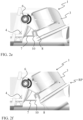
- FIG. 1a is an exemplary of a propulsion system 1 for a marine vessel 100, according to an example.
- the propulsion system 1 comprises a transom bracket 2 configured to be connected to a transom 101 of the marine vessel 100.
- the propulsion system 1 also comprises a drive unit 3 being rotatably connected with the transom bracket 2 so as to be pivotable by a tilt arrangement 4 from a lowered position LP as shown in FIG. 1a into a raised position RP, or vice versa, about a pivot joint 6, and a trim arrangement 7 being arranged between the transom bracket 2 and the drive unit 3 to adjust a trim angle of the drive unit 3 when in the lowered position LP.
- the propulsion system 1 furthermore comprises a trim arrangement lock 8 being arranged to be connected with the trim arrangement 7 for a range of trim angles of the drive unit 3 in the lowered position LP so as to prevent pivoting of the drive unit 3 by the tilt arrangement 4 inside the range of trim angles, and the trim arrangement lock 8 is configured to be disconnected from the trim arrangement 7 outside the range of trim angles so as to allow pivoting of the drive unit 3 by the tilt arrangement 4.
- the drive unit 3 is positioned in the lowered position LP both while providing the forward thrust and the backward thrust since the trim arrangement lock prevents pivoting by tilt arrangement in the lowered position, for a predetermined range of trim angles, so that the tilt arrangement is configured to follow the rotation of the drive unit within the range of trim angles.
- the trim arrangement 7 since the trim arrangement 7 is dedicated to the trim function of the drive unit 3 less power is necessary for tilt arrangement 4, and thereby the tilt arrangement 4 may be smaller in size compared to the known solutions.
- the drive unit 3 may comprises one or more propellers.
- the one or more propellers may be configured to push the marine vessel 100 in a forward motion of the marine vessel, or the one or more propellers may be configured to pull the marine vessel 100 in a forward motion of the marine vessel.
- the one or more propellers may provide the thrust.
- the drive unit 3 comprises a first propeller 13a and a second propeller 13b.
- the first propeller 13a may be arranged to be counter-rotating compared to the second propeller 13b.
- the drive unit 3 may comprise an electric motor for powering the one or more propellers.
- a combustion engine may be arranged.
- the drive unit may comprise a water jet as thrust.
- the trim arrangement 7 has trimmed the drive unit 3 outside the predetermined range of trim angles whereby the trim arrangement lock 8 is arranged to be disconnected from the trim arrangement 7.
- the drive unit 3 may be further rotated about the pivot joint 6 by the tilt arrangement.
- the trim arrangement lock 8 is arranged on the drive unit 3.
- the trim arrangement lock 8 may be arranged at the transom bracket.
- the trim arrangement 7 comprises at least one linear trim actuator 7.
- the linear trim actuator 7 may have a connection part 10 arranged at an end of the linear trim actuator 7.
- the connection part 7 may be arranged in the end opposite the transom bracket 2. In another example, the connection part may be arranged at the end opposite the drive unit 2.
- connection part 10 An opposite end of the linear trim actuator 7 compared to the connection part 10 is connected to the transom bracket 2, or the drive unit.
- the trim arrangement lock 8 and the connection part 10 are geometrically engaged inside the range of trim angles and are disengaged outside the range of trim angles.
- the trim arrangement lock 8 and the connection part 10 are geometrically engaged inside the range of trim angles.
- the trim arrangement lock 8 and the connection part 10 are disengaged outside the range of trim angles.
- the trim arrangement lock 8 is configured to be moved along a trajectory of a rotation radius having the pivot joint 6 as a centre.
- the tilt arrangement 4 is configured to follow the rotation of the drive unit 3 inside the range of trim angles.
- the trim arrangement lock or the trim arrangement is configured to follow the drive unit 3 when it is pivoted inside the range of trim angles, and the trim arrangement lock is configured to be connected with the connecting part inside the range of trim angles.
- the trim arrangement lock is disconnected from the connecting part and thereby the drive unit may be tilted to the raised position by the tilt arrangement further long the trajectory.
- trim arrangement lock and the movement of either the trim arrangement lock or the trim arrangement ensures that the connection between the trim arrangement lock and the trim arrangement is obtained automatically within the range of trim angles and that the disconnection is obtained automatically outside the range of trim angles. This is obtained by a geometrically relationship between trim arrangement lock and the trim arrangement. Furthermore, no additional locking parts are necessary for locking and maintaining the trim arrangement lock to the trim arrangement.
- the opposite end of the linear trim actuator 7 is securely fastened to the transom bracket 2.
- the opposite end of the linear trim actuator 7 is securely fastened to the drive unit.
- the opposite end of the linear trim actuator 7 projects from either the transom bracket 2 or the drive unit 3 in a fixed angle.
- FIGS. 2a-2f a sequence of trim and tilt of a drive unit 3 according to an example is shown.
- the example shown corresponds to the example shown in FIGS. 1a-1b .
- the drive unit 3 is in the lowered position LP, wherein the trim arrangement 7 is trimming the drive unit 3 to be in a neutral trim angle.
- the trim arrangement 7 is trimming the drive unit 3 about the pivot joint 6.
- the connection part 10 of the trim arrangement 7 is geometrically engaged with the trim arrangement lock 8 inside the range of trim angles.
- the drive unit 3 is still in the lowered position LP, wherein the trim arrangement 7 is trimming the drive unit 3 to be in a negative trim angle.
- the trim arrangement 7 is trimming the drive unit 3 about the pivot joint 6 by rotating the drive unit 3 in the rotation direction shown in FIG. 2b .
- the linear actuator 7 is pulling the drive unit 3 towards the transom bracket 2 whereby the drive unit is being trimmed to the negative trim angle.
- the connection part 10 of the trim arrangement 7 is geometrically is still engaged with the trim arrangement lock 8 inside the range of trim angles.
- the drive unit 3 in FIG. 2c is trimmed to a positive trim angle by the trim arrangement 7.
- the drive unit 3 is still in the lowered position LP.
- the trim arrangement 7 is trimming the drive unit 3 about the pivot joint 6 by rotating the drive unit 3 in the rotation direction shown in FIG. 2c .
- the linear actuator 7 is pushing the drive unit 3 away the transom bracket 2 whereby the drive unit is being trimmed to the positive trim angle.
- the connection part 10 of the trim arrangement 7 is geometrically is still engaged with the trim arrangement lock 8 inside the range of trim angles.
- the drive unit 3 in FIG. 2d is trimmed to a higher positive trim angle by the trim arrangement 7.
- the drive unit 3 is still in the lowered position LP.
- the trim arrangement 7 is trimming the drive unit 3 about the pivot joint 6 by further rotating the drive unit 3 in the rotation direction shown in FIG. 2d .
- the linear actuator 7 is pushing the drive unit 3 further away the transom bracket 2 whereby the drive unit is being trimmed to the positive trim angle about the pivot joint 6.
- the connection part 10 of the trim arrangement 7 is geometrically is still engaged with the trim arrangement lock 8 inside the range of trim angles.
- the drive unit 3 is outside the range of trim angles.
- the connecting part 10 of the linear actuator 7 is being disengaged from the trim arrangement lock 8 in FIG. 2e , whereby the linear actuator 7 is not trimming the drive unit 3.
- the tilt arrangement 4 is configured to rotate the drive unit 3 further about the pivot joint 6 in the direction shown in FIG. 2e .
- the drive unit 3 has been tilted further up towards the raised position RP by the tilt arrangement 4 is rotating the drive unit 3 further about the pivot joint 6.
- the tilt arrangement and trim arrangement are configured to function together, however, are separate arrangements.
- the tilt arrangement 4 is configured to follow the rotation of the drive unit 3 inside the range of trim angles as shown in FIGS. 2a-2d , and to tilt the drive unit 3 outside the range of trim angles as shown in FIGS. 2e-2f .
- the tilt arrangement 4 comprises a linear tilt actuator 4 and/or a rotation motor.
- the tilt arrangement is a linear tilt actuator 4.
- the linear tilt actuator 4 may be a hydraulic cylinder, or it may be a pneumatic cylinder.
- the rotation motor may be electric.
- FIGS. 3a -2g another sequence of trim and tilt of a drive unit 3 according to an example is shown.
- the drive unit 3 is in the lowered position LP, wherein the trim arrangement 7 is trimming the drive unit 3 to be in a neutral trim angle.
- the trim arrangement 7 is trimming the drive unit 3.
- the connection part 10 of the trim arrangement 7 is geometrically engaged with the trim arrangement lock 8 inside the range of trim angles.
- the connection part 10 is a slot or recess arranged in an end of the trim arrangement 7 and the trim arrangement lock 8 is a projection arranged on the drive unit 3.
- the drive unit 3 is still in the lowered position LP, wherein the trim arrangement 7 is trimming the drive unit 3 to be in a negative trim angle.
- the trim arrangement 7 is trimming the drive unit 3 about the pivot j oint.
- the linear actuator 7 is pulling the drive unit 3 towards the transom bracket 2 whereby the drive unit is being trimmed to the negative trim angle.
- the connection part 10 of the trim arrangement 7 is geometrically still engaged with the trim arrangement lock 8 inside the range of trim angles.
- the drive unit 3 in FIG. 3c is trimmed to a positive trim angle by the trim arrangement 7.
- the drive unit 3 is still in the lowered position LP.
- the trim arrangement 7 is trimming the drive unit 3 about the pivot joint.
- the linear actuator 7 is pushing the drive unit 3 away the transom bracket 2 whereby the drive unit 3 is being trimmed to the positive trim angle.
- the connection part 10 of the trim arrangement 7 is geometrically is still engaged with the trim arrangement lock 8 inside the range of trim angles.
- the drive unit 3 in FIG. 3d is trimmed to a higher positive trim angle by the trim arrangement 7.
- the drive unit 3 is still in the lowered position LP.
- the trim arrangement 7 is trimming the drive unit 3 about the pivot j oint.
- the linear actuator 7 is pushing the drive unit 3 further away the transom bracket 2 whereby the drive unit is being trimmed to the positive trim angle about the pivot joint 6.
- the connection part 10 of the trim arrangement 7 is geometrically still engaged with the trim arrangement lock 8 inside the range of trim angles but the drive unit 3 is in FIG. 3d very close to be outside the range of trim angles whereby the connection part 10 and the trim arrangement lock 8 are disengaged.
- the drive unit 3 is outside the range of trim angles.
- the connecting part 10 of the linear actuator 7 is being disengaged from the trim arrangement lock 8 in FIG. 3e , whereby the linear actuator 7 is not trimming the drive unit 3.
- the tilt arrangement is configured to rotate the drive unit 3 further about the pivot joint.
- the drive unit 3 has been tilted further up towards the raised position RP by the tilt arrangement is rotating the drive unit 3 further about the pivot j oint.
- the trim arrangement 7 has been retracted towards the transom bracket 2.
- the drive unit 3 is in the raised position RP.
- the trim arrangement lock 8 is configured to receive the connection part 10 or the connection part 10 is configured to receive the trim arrangement lock 8 inside the range of trim angles and otherwise being disengaged.
- the trim arrangement lock 8 may be configured to receive the connection part 10 of the linear trim actuator 7 or is configured to engage the connection part 10.
- the trim arrangement lock 8 may comprise a receptacle, a slot, a recess, a bended member, a U-formed member, an inverted U-formed member, a helically or spirally formed member, or similar, when being configured to receive the connecting part 10.
- the trim arrangement lock 8 may have an inlet through which the connecting part 10 can enter or leave outside the range of trim angles and a face being configured to maintain the connection part 10 in the trim arrangement lock 8 inside the range of trim angles.
- the inlet may taper so as assisting the connecting part 10 in enter and leaving the trim arrangement lock 8.
- the connecting part 10 may comprise a geometrical shape configured to engage the trim arrangement lock 8, such as a projection, a spherical member, a knob, a recess, a slot or similar.
- the trim arrangement lock 8 may comprise a projection, a spherical member, a knob, or similar when being configured to engage the connecting part.
- trim arrangement lock 8 may be made of a rigid material, such as metal.
- the trim arrangement 7 is spiral-formed and comprises a rotatory actuator or motor 15.
- the rotatory motor 15 is configured to rotate the spiral-formed trim arrangement 7 in both directions so as the drive unit may be trimmed within the range of trim angles.
- the trim arrangement 7 also comprises a spiral-formed track 16.
- the trim arrangement lock 8 is configured to be guided in the spiral-formed track 16 within the range of trim angels and thereby being connected with the trim arrangement.
- the trim arrangement 7 is arranged on the transom bracket and the trim arrangement lock 8 is arranged on the drive unit 3. As the drive unit 3 is being pivoted outside the range of the trim angles the trim arrangement lock 8 is moved out spiral-formed track 16 and thereby disconnected so that the drive unit 3 may be tilted.
- the spiral-formed trim arrangement 7 may be arranged on the drive unit 3 and the trim arrangement lock 8 is arranged on the transom bracket.
- the trim arrangement 7 may comprise a plurality of linear trim actuators or rotatory trim actuators and a corresponding number of trim arrangement locks.
- the propulsion system may comprise a kick up function.
- the present disclosure also relates to a marine vessel 100 comprising a transom and a propulsion system 1 as described above.
- the present disclosure also relates to a method for trimming and tilting a drive unit 3 of a propulsion system 1, comprising
- the method may further comprising
- Example 1 A propulsion system (1) for a marine vessel (100), comprising a transom bracket (2) configured to be connected to a transom of the marine vessel, a drive unit (3) being rotatably connected with the transom bracket (2) so as to be pivotable by a tilt arrangement (4) from a lowered position (LP) into a raised position (RP), or vice versa, about a pivot joint (6), and
- Example 2 The propulsion system (1) of example 1, wherein the trim arrangement (7) comprises at least one linear trim actuator (7) or rotatory trim actuator, the trim actuator has a connection part (10) arranged at an end of the trim actuator.
- Example 3 The propulsion system (1) of example 2, wherein the connection part (10) is arranged at the end opposite the drive unit.
- Example 4 The propulsion system (1) of example 2, wherein the connection part (10) is arranged in the end opposite the transom bracket.
- Example 5 The propulsion system (1) of any of the examples 2-4, wherein an opposite end of the trim actuator (7) compared to the connection part (10) is connected to the transom bracket or the drive unit.
- Example 6 The propulsion system (1) of example 5, wherein the opposite end of the trim actuator (7) is securely fastened to either the transom bracket or the drive unit.
- Example7 The propulsion system (1) of example 6, wherein the opposite end of the trim actuator (7) projects from either the transom bracket or the drive unit in a fixed angle.
- Example 8 The propulsion system (1) of any of the preceding examples, wherein trim arrangement lock (8) is arranged on the drive unit or at the transom bracket.
- Example 9 The propulsion system (1) of example 8, wherein the trim arrangement lock (8) is securely arranged on the drive unit or on the transom bracket.
- Example 10 The propulsion system (1) of any of examples 2-9, wherein the trim arrangement lock (8) is configured to receive the connection part (10) or the connection part (10) is configured to receive the trim arrangement lock inside the range of trim angles and otherwise being disengaged.
- Example 11 The propulsion system (1) of example 10, wherein the trim arrangement lock (8) and the connection part (10) are geometrically engaged inside the range of trim angles and are disengaged outside the range of trim angles.
- Example 12 The propulsion system (1) of any of the preceding examples, wherein the trim arrangement lock (8) or the trim arrangement is configured to be moved along a trajectory of a rotation radius having the pivot joint (6) as a centre.
- Example 13 The propulsion system (1) of any of the preceding examples, wherein the tilt arrangement (4) is configured to follow the rotation of the drive unit (3) inside the range of trim angles.
- Example 14 The propulsion system (1) of any of the preceding examples, wherein the trim arrangement (7) comprises a plurality of linear trim actuators (7) or a plurality of rotatory trim actuators, and a corresponding number of trim arrangement locks (8).
- Example 15 The propulsion system (1) of any of the preceding examples, wherein the tilt arrangement (4) comprises a linear tilt actuator and/or a rotatory actuator or motor.
- Example 16 The propulsion system (1) of any of the preceding examples, wherein the trim arrangement lock (8) is configured to receive the connection part (10) of the trim actuator or is configured to engage the connection part.
- Example 17 The propulsion system (1) of example 16, wherein the trim arrangement lock (8) and the connection part (10) are geometrically connected and/or engaged inside the range of trim angles.
- Example 18 The propulsion system (1) of example 16-17, wherein the trim arrangement lock (8) comprises a receptacle, a slot, a recess, a bended member, a U-formed member, an inverted U-formed member, a helically or spirally formed member, or similar, when being configured to receive the connecting part (10).
- the trim arrangement lock (8) comprises a receptacle, a slot, a recess, a bended member, a U-formed member, an inverted U-formed member, a helically or spirally formed member, or similar, when being configured to receive the connecting part (10).
- Example 19 The propulsion system (1) of example 18, wherein the trim arrangement lock (8) has an inlet through which the connecting part (10) can enter or leave outside the range of trim angles and a face being configured to maintain the connection part in the trim arrangement lock inside the range of trim angles.
- Example 20 The propulsion system (1) of example 19, wherein the inlet tapers so as assisting the connecting part (10) in enter and leaving the trim arrangement lock (8).
- Example 21 The propulsion system (1) of claim 18-20, wherein the connecting part (10) comprises a geometrical shape configured to engage the trim arrangement lock (8), such as a projection, a spherical member, a knob, or similar.
- the connecting part (10) comprises a geometrical shape configured to engage the trim arrangement lock (8), such as a projection, a spherical member, a knob, or similar.
- Example 22 The propulsion system (1) of example 16-17, wherein the trim arrangement lock (8) comprises a projection, a spherical member, a knob, or similar when being configured to engage the connecting part (10).
- Example 23 The propulsion system (1) of example 22, wherein the connecting part (10) comprises a geometrical shape configured to receive the trim arrangement lock (8), such as a receptacle, a slot, a recess, a bended member, a U-formed member, an inverted U-formed member, a helically or spirally formed member, or similar.
- the trim arrangement lock (8) such as a receptacle, a slot, a recess, a bended member, a U-formed member, an inverted U-formed member, a helically or spirally formed member, or similar.
- Example 24 The propulsion system (1) of any of the preceding examples, wherein the trim arrangement lock (8) is made of a rigid material, such as metal.
- Example 25 The propulsion system (1) of any of the preceding examples, wherein the drive unit (3) comprises an electric motor.
- Example 26 The propulsion system (1) of any of the preceding examples, wherein the drive unit (3) is configured to be trimmed by the trim arrangement (7) and titled around the pivot joint (51) by the tilt arrangement (4).
- Example 27 The propulsion system (1) of example 15, wherein the rotation motor is electric, or the linear tilt actuator (4) is a hydraulic cylinder or a pneumatic cylinder.
- Example 28 The propulsion system (1) of example 2, wherein the linear trim actuator (7) is a hydraulic cylinder or a pneumatic cylinder.
- Example 29 The propulsion system (1) of any of the preceding examples, wherein the drive unit (3) comprises one or more propellers.
- Example 30 The propulsion system (1) of example 29, wherein the one or more propellers are configured to push the marine vessel (100) in a forward motion of the marine vessel.
- Example 31 The propulsion system (1) of example 29, wherein the one or more propellers are configured to pull the marine vessel (100) in a forward motion of the marine vessel.
- Example 32 The propulsion system (1) of example 29, wherein the drive unit (3) comprises a first propeller (13a) and a second propeller (13b).
- Example 33 The propulsion system (1) of example 32, wherein the first propeller (13a) is arranged to be counter-rotating compared to the second propeller (13b).
- Example 34 The propulsion system (1) of any of the preceding examples, further comprising a control unit configured to control the trim arrangement (7) and/or the tilt arrangement (4).
- Example 35 The propulsion system (1) of any of the preceding examples, further comprising a kick up function.
- Example 36 The propulsion system (1) of example 1, wherein the trim arrangement (7) comprises a spiral-formed track (16) and a rotatory motor (15) configured to rotate the spiral-formed track (16).
- Example 37 The propulsion system (1) of example 36, wherein the trim arrangement lock (8) is configured to the guided in the spiral-formed track (16) within the range of trim angles.
- Example 38 A marine vessel (100) comprising a transom and a propulsion system (1) of any of the preceding examples.
- Example 39 A method for trimming and tilting a drive unit (3) of a propulsion system (1), comprising
- Example 40 A method of example 39, comprising
- Relative terms such as “below” or “above” or “upper” or “lower” or “horizontal” or “vertical” may be used herein to describe a relationship of one element to another element as illustrated in the Figures. It will be understood that these terms and those discussed above are intended to encompass different orientations of the device in addition to the orientation depicted in the Figures. It will be understood that when an element is referred to as being “connected” or “coupled” to another element, it can be directly connected or coupled to the other element, or intervening elements may be present. In contrast, when an element is referred to as being “directly connected” or “directly coupled” to another element, there are no intervening elements present.
Landscapes
- Chemical & Material Sciences (AREA)
- Engineering & Computer Science (AREA)
- Combustion & Propulsion (AREA)
- Mechanical Engineering (AREA)
- Ocean & Marine Engineering (AREA)
- Lock And Its Accessories (AREA)
- Transmission Devices (AREA)
Abstract
The disclosure relates to a propulsion system for a marine vessel, comprising a transom bracket configured to be connected to a transom of the marine vessel, a drive unit being rotatably connected with the transom bracket so as to be pivotable by a tilt arrangement from a lowered position into a raised position, or vice versa, about a pivot joint, and a trim arrangement being arranged between the transom bracket and the drive unit to adjust a trim angle of the drive unit when in the lowered position, further comprising a trim arrangement lock being arranged to be connected with the trim arrangement for a range of trim angles of the drive unit in the lowered position so as to prevent pivoting of the drive unit by the tilt arrangement inside the range of trim angles, and the trim arrangement lock is configured to be disconnected from the trim arrangement outside the range of trim angles so as to allow pivoting of the drive unit by the tilt arrangement.
Description
- The disclosure relates generally to a propulsion system. In particular aspects, the disclosure relates to a propulsion system for a marine vessel. The disclosure can be applied to marine vessels, such as water crafts, motorboats, work boats, sport vessels, boats, ships, among other vessel types. Although the disclosure may be described with respect to a particular marine vessel, the disclosure is not restricted to any particular marine vessel.
- Propulsion systems for marine vessels are known. These propulsions systems having a drive unit which may be trimmed so as to improve the marine vessel's performance and energy consumption to power the drive unit. The propulsion systems sometimes have a tilt mechanism to raise and to lower the drive unit out from and into the water so that the drive unit may be positioned above water level. The trim mechanism is arranged so as to function during both forward and reverse thrust. For the drive unit function properly under reverse thrust the drive unit has some kind of mechanism maintaining the drive unit in position under the reverse thrust for not damaging the vessel, bracket and/or the drive unit. However, known mechanism shall sometime be activated by an operator who may forget to activate it. Other automatic mechanisms exist, however, these mechanisms are rather advanced and may malfunction.
- According to a first aspect of the disclosure, a propulsion system for a marine vessel, comprising a transom bracket configured to be connected to a transom of the marine vessel, a drive unit being rotatably connected with the transom bracket so as to be pivotable by a tilt arrangement from a lowered position into a raised position, or vice versa, about a pivot j oint, and a trim arrangement being arranged between the transom bracket and the drive unit to adjust a trim angle of the drive unit when in the lowered position, further comprising a trim arrangement lock being arranged to be connected with the trim arrangement for a range of trim angles of the drive unit in the lowered position so as to prevent pivoting of the drive unit by the tilt arrangement inside the range of trim angles, and the trim arrangement lock is configured to be disconnected from the trim arrangement outside the range of trim angles so as to allow pivoting of the drive unit by the tilt arrangement. The first aspect of the disclosure may seek to the disadvantages with the known solutions, and especially ensuring that the drive unit may be maintained in position while providing a forward thrust or a backward thrust without jeopardizing the possibilities for trimming the drive unit. A technical benefit may include that the drive unit is positioned in the lowered position both while providing the forward thrust and the backward thrust since the trim arrangement lock prevents pivoting by tilt arrangement in the lowered position, for a predetermined range of trim angles so that the tilt arrangement is configured to follow the rotation of the drive unit within the range of trim angles. In addition, since the trim arrangement is dedicated to the trim function of the drive unit less power is necessary for tilt function, and thereby the tilt arrangement may be smaller in size compared to the known solutions.
- Optionally in some examples, including in at least one preferred example, the trim arrangement comprises at least one linear trim actuator or rotatory trim actuator, the trim actuator has a connection part arranged at an end of the trim actuator. A technical benefit may include that a reliable trim arrangement being capable of transferring high forces.
- Optionally in some examples, including in at least one preferred example, the connection part is arranged at the end opposite the drive unit or the connection part is arranged in the end opposite the transom bracket. A technical benefit may include design freedom to where the trim arrangement lock may be arranged.
- Optionally in some examples, including in at least one preferred example, an opposite end of the trim actuator compared to the connection part is connected to the transom bracket or the drive unit. A technical benefit may include design freedom to where the trim actuator is connected.
- Optionally in some examples, including in at least one preferred example, the opposite end of the trim actuator is securely fastened to either the transom bracket or the drive unit. A technical benefit may include design freedom to where the trim actuator is fastened. In addition, the trim actuator is securely fastened in the opposite end of the connecting part, which is disconnectable from the trim arrangement lock. Hence, when the connecting part is disconnected from the trim arrangement lock it may be free for any connection since the opposite end of the trim actuator will maintain and position it.
- Optionally in some examples, including in at least one preferred example, the opposite end of the trim actuator projects from either the transom bracket or the drive unit in a fixed angle. A technical benefit may include that the projecting angle of the trim actuator is arranged so as to provide that the connecting part of the linear trim actuator may be connected with the trim arrangement lock inside the range of trim angles and be disconnected outside the range of trim angles.
- Optionally in some examples, including in at least one preferred example, the trim arrangement lock is arranged on the drive unit or at the transom bracket. A technical benefit may include design freedom to where the trim arrangement lock is arranged.
- Optionally in some examples, including in at least one preferred example, the trim arrangement lock is configured to receive the connection part or the connection part is configured to receive the trim arrangement lock inside the range of trim angles and otherwise being disengaged. A technical benefit may include a reliable way to connect to and disconnect from the trim arrangement lock without the assistance of other external locking devices.
- Optionally in some examples, including in at least one preferred example, the trim arrangement lock and the connection part are geometrically engaged inside the range of trim angles and are disengaged outside the range of trim angles. A technical benefit may include that the geometry of the trim arrangement lock and the connection part are connecting the trim actuator with the trim arrangement lock inside the range of trim angles, i.e. the pivoting of the drive unit inside the range of trim angles.
- Optionally in some examples, including in at least one preferred example, the trim arrangement lock or the trim arrangement is configured to be moved along a trajectory of a rotation radius having the pivot joint as a centre. A technical benefit may include that when the trim arrangement lock or the trim arrangement follows the drive unit when it is pivoted inside the range of trim angles the trim arrangement lock is configured to be connected with the connecting part. When the drive unit is pivoted outside the range of trim angles the trim arrangement lock is disconnected from the connecting part and thereby the drive unit may be tilted to the raised position by the tilt arrangement further long the trajectory. The combination of the trim arrangement lock and the movement ensures that the connection between the trim arrangement lock and the trim arrangement is obtained automatically within the range of trim angles and that the disconnection is obtained automatically outside the range of trim angles.
- Optionally in some examples, including in at least one preferred example, the tilt arrangement is configured to follow the rotation of the drive unit inside the range of trim angles. A technical benefit may include that the trim arrangement is configured to perform the pivoting/trim of the drive unit inside the range of trim angles where it may be necessary to use a high force due speed of the marine vessel and/or acceleration, whereby the tilt arrangement simply may be set to follow the pivoting of the drive unit without consuming power or force.
- Optionally in some examples, including in at least one preferred example, the tilt arrangement comprises a linear tilt actuator and/or a rotatory actuator or motor. A technical benefit may include that a reliable tilt arrangement is provided and obtained.
- Optionally in some examples, including in at least one preferred example, the trim arrangement lock comprises a receptacle, a slot, a recess, a bended member, a U-formed member, an inverted U-formed member, a helically or spirally formed member, or similar, when being configured to receive the connecting part. A technical benefit may include providing a shape and/or geometry of the trim arrangement lock for facilitating that the connecting part easily may be engaged or connected to the trim arrangement lock.
- Optionally in some examples, including in at least one preferred example, the trim arrangement lock has an inlet through which the connecting part can enter or leave outside the range of trim angles and a face being configured to maintain the connection part in the trim arrangement lock inside the range of trim angles. A technical benefit may include facilitating that the connecting part may be maintained in the trim arrangement lock inside the range of trim angles and disengaged otherwise as well as engaged again when approaching the range of trim angles again.
- Optionally in some examples, including in at least one preferred example, the inlet tapers so as assisting the connecting part in enter and leaving the trim arrangement lock. A technical benefit may include assisting in the engagement and disengagement of the connecting part in and out of the trim arrangement lock. In addition, the tapering may also compensate of any misalignment between the connecting part and the inlet when the drive unit is being pivoted.
- Optionally in some examples, including in at least one preferred example, the connecting part comprises a geometrical shape configured to engage the trim arrangement lock, such as a projection, a spherical member, a knob, or similar. A technical benefit may include facilitating that the connecting part may be maintained in the trim arrangement lock inside the range of trim angles and disengaged otherwise as well as engaged again when approaching the range of trim angles again.
- Optionally in some examples, including in at least one preferred example, the trim arrangement lock comprises a projection, a spherical member, a knob, or similar when being configured to engage the connecting part. A technical benefit may include facilitating that the trim arrangement lock may be maintained in the connecting part inside the range of trim angles and disengaged otherwise as well as be reengaged when approaching the range of trim angles again.
- Optionally in some examples, including in at least one preferred example, the connecting part comprises a geometrical shape configured to receive the trim arrangement lock, such as a receptacle, a slot, a recess, a bended member, a U-formed member, an inverted U-formed member, a helically or spirally formed member, or similar. A technical benefit may include that the trim arrangement lock may be maintained in the connecting part inside the range of trim angles and disengaged otherwise as well as be reengaged when approaching the range of trim angles again.
- According to a second aspect of the disclosure, a marine vessel comprising a transom and a propulsion system as described above.
- According to a third aspect of the disclosure, a method for trimming and tilting a drive unit of a propulsion system, comprising
- arranging a propulsion system as described above on a marine vessel,
- arranging the drive unit in the lowered position,
- trimming the drive unit by the trim arrangement inside a range of trim angles while the trim arrangement is connected with the trim arrangement lock,
- pivoting the drive unit outside the range of trim angles so that the trim arrangement is disconnected from the trim arrangement lock,
- tilting the drive unit to the raised position by the tilt arrangement.
- The disclosed aspects, examples (including any preferred examples), and/or accompanying claims may be suitably combined with each other as would be apparent to anyone of ordinary skill in the art. Additional features and advantages are disclosed in the following description, claims, and drawings, and in part will be readily apparent therefrom to those skilled in the art or recognized by practicing the disclosure as described herein.
- Examples are described in more detail below with reference to the appended drawings.
-
FIGS. 1a-1b are an exemplary of a propulsion system according to an example. -
FIGS. 2a-2f show a sequence of trim and tilt of a drive unit according to an example. -
FIGS. 3a-3f show a sequence of trim and tilt of a drive unit according to another example. -
FIG. 4 is an exemplary of a trim arrangement according to an example. - The detailed description set forth below provides information and examples of the disclosed technology with sufficient detail to enable those skilled in the art to practice the disclosure.
-
FIG. 1a is an exemplary of apropulsion system 1 for amarine vessel 100, according to an example. Thepropulsion system 1 comprises atransom bracket 2 configured to be connected to atransom 101 of themarine vessel 100. Thepropulsion system 1 also comprises adrive unit 3 being rotatably connected with thetransom bracket 2 so as to be pivotable by atilt arrangement 4 from a lowered position LP as shown inFIG. 1a into a raised position RP, or vice versa, about a pivot joint 6, and atrim arrangement 7 being arranged between thetransom bracket 2 and thedrive unit 3 to adjust a trim angle of thedrive unit 3 when in the lowered position LP. Thepropulsion system 1 furthermore comprises atrim arrangement lock 8 being arranged to be connected with thetrim arrangement 7 for a range of trim angles of thedrive unit 3 in the lowered position LP so as to prevent pivoting of thedrive unit 3 by thetilt arrangement 4 inside the range of trim angles, and thetrim arrangement lock 8 is configured to be disconnected from thetrim arrangement 7 outside the range of trim angles so as to allow pivoting of thedrive unit 3 by thetilt arrangement 4. Hereby is obtained that that thedrive unit 3 is positioned in the lowered position LP both while providing the forward thrust and the backward thrust since the trim arrangement lock prevents pivoting by tilt arrangement in the lowered position, for a predetermined range of trim angles, so that the tilt arrangement is configured to follow the rotation of the drive unit within the range of trim angles. In addition, since thetrim arrangement 7 is dedicated to the trim function of thedrive unit 3 less power is necessary fortilt arrangement 4, and thereby thetilt arrangement 4 may be smaller in size compared to the known solutions. - In addition, the
drive unit 3 may comprises one or more propellers. The one or more propellers may be configured to push themarine vessel 100 in a forward motion of the marine vessel, or the one or more propellers may be configured to pull themarine vessel 100 in a forward motion of the marine vessel. The one or more propellers may provide the thrust. - In the example shown in
FIG. 1a , thedrive unit 3 comprises afirst propeller 13a and asecond propeller 13b. Thefirst propeller 13a may be arranged to be counter-rotating compared to thesecond propeller 13b. - The
drive unit 3 may comprise an electric motor for powering the one or more propellers. In another example, a combustion engine may be arranged. - In an example, the drive unit may comprise a water jet as thrust.
- In
FIG. 1b , thetrim arrangement 7 has trimmed thedrive unit 3 outside the predetermined range of trim angles whereby thetrim arrangement lock 8 is arranged to be disconnected from thetrim arrangement 7. Hereby, thedrive unit 3 may be further rotated about the pivot joint 6 by the tilt arrangement. In the example shown inFIG. 1b , thetrim arrangement lock 8 is arranged on thedrive unit 3. In another example, thetrim arrangement lock 8 may be arranged at the transom bracket. - In the example, the
trim arrangement 7 comprises at least onelinear trim actuator 7. In the example the lineartrim actuator 7 may have aconnection part 10 arranged at an end of the lineartrim actuator 7. Theconnection part 7 may be arranged in the end opposite thetransom bracket 2. In another example, the connection part may be arranged at the end opposite thedrive unit 2. - An opposite end of the linear
trim actuator 7 compared to theconnection part 10 is connected to thetransom bracket 2, or the drive unit. - The
trim arrangement lock 8 and theconnection part 10 are geometrically engaged inside the range of trim angles and are disengaged outside the range of trim angles. InFIG. 1a , thetrim arrangement lock 8 and theconnection part 10 are geometrically engaged inside the range of trim angles. InFIG. 1b , thetrim arrangement lock 8 and theconnection part 10 are disengaged outside the range of trim angles. - The
trim arrangement lock 8 is configured to be moved along a trajectory of a rotation radius having the pivot joint 6 as a centre. Thetilt arrangement 4 is configured to follow the rotation of thedrive unit 3 inside the range of trim angles. According to the disclosure, the trim arrangement lock or the trim arrangement is configured to follow thedrive unit 3 when it is pivoted inside the range of trim angles, and the trim arrangement lock is configured to be connected with the connecting part inside the range of trim angles. When the drive unit is pivoted outside the range of trim angles, the trim arrangement lock is disconnected from the connecting part and thereby the drive unit may be tilted to the raised position by the tilt arrangement further long the trajectory. The combination of the trim arrangement lock and the movement of either the trim arrangement lock or the trim arrangement ensures that the connection between the trim arrangement lock and the trim arrangement is obtained automatically within the range of trim angles and that the disconnection is obtained automatically outside the range of trim angles. This is obtained by a geometrically relationship between trim arrangement lock and the trim arrangement. Furthermore, no additional locking parts are necessary for locking and maintaining the trim arrangement lock to the trim arrangement. - In the example shown in
FIGS. 1a-1b , the opposite end of the lineartrim actuator 7 is securely fastened to thetransom bracket 2. In another example, the opposite end of the lineartrim actuator 7 is securely fastened to the drive unit. In addition, the opposite end of the lineartrim actuator 7 projects from either thetransom bracket 2 or thedrive unit 3 in a fixed angle. Hereby is obtained that the trim arrangement lock and the trim arrangement may geometrically engage without the need for any additional components. - In
FIGS. 2a-2f , a sequence of trim and tilt of adrive unit 3 according to an example is shown. The example shown corresponds to the example shown inFIGS. 1a-1b . InFIG. 2a , thedrive unit 3 is in the lowered position LP, wherein thetrim arrangement 7 is trimming thedrive unit 3 to be in a neutral trim angle. Thetrim arrangement 7 is trimming thedrive unit 3 about thepivot joint 6. Theconnection part 10 of thetrim arrangement 7 is geometrically engaged with thetrim arrangement lock 8 inside the range of trim angles. InFIG. 2b , thedrive unit 3 is still in the lowered position LP, wherein thetrim arrangement 7 is trimming thedrive unit 3 to be in a negative trim angle. Thetrim arrangement 7 is trimming thedrive unit 3 about the pivot joint 6 by rotating thedrive unit 3 in the rotation direction shown inFIG. 2b . Thelinear actuator 7 is pulling thedrive unit 3 towards thetransom bracket 2 whereby the drive unit is being trimmed to the negative trim angle. Theconnection part 10 of thetrim arrangement 7 is geometrically is still engaged with thetrim arrangement lock 8 inside the range of trim angles. - Compared to
FIG. 2b , thedrive unit 3 inFIG. 2c is trimmed to a positive trim angle by thetrim arrangement 7. Thedrive unit 3 is still in the lowered position LP. Thetrim arrangement 7 is trimming thedrive unit 3 about the pivot joint 6 by rotating thedrive unit 3 in the rotation direction shown inFIG. 2c . Thelinear actuator 7 is pushing thedrive unit 3 away thetransom bracket 2 whereby the drive unit is being trimmed to the positive trim angle. Theconnection part 10 of thetrim arrangement 7 is geometrically is still engaged with thetrim arrangement lock 8 inside the range of trim angles. - Compared to
FIG. 2c , thedrive unit 3 inFIG. 2d is trimmed to a higher positive trim angle by thetrim arrangement 7. Thedrive unit 3 is still in the lowered position LP. Thetrim arrangement 7 is trimming thedrive unit 3 about the pivot joint 6 by further rotating thedrive unit 3 in the rotation direction shown inFIG. 2d . Thelinear actuator 7 is pushing thedrive unit 3 further away thetransom bracket 2 whereby the drive unit is being trimmed to the positive trim angle about thepivot joint 6. Theconnection part 10 of thetrim arrangement 7 is geometrically is still engaged with thetrim arrangement lock 8 inside the range of trim angles. - In
FIGS. 2e-2f , thedrive unit 3 is outside the range of trim angles. The connectingpart 10 of thelinear actuator 7 is being disengaged from thetrim arrangement lock 8 inFIG. 2e , whereby thelinear actuator 7 is not trimming thedrive unit 3. Thetilt arrangement 4 is configured to rotate thedrive unit 3 further about the pivot joint 6 in the direction shown inFIG. 2e . InFIG. 2f , thedrive unit 3 has been tilted further up towards the raised position RP by thetilt arrangement 4 is rotating thedrive unit 3 further about thepivot joint 6. The tilt arrangement and trim arrangement are configured to function together, however, are separate arrangements. - The
tilt arrangement 4 is configured to follow the rotation of thedrive unit 3 inside the range of trim angles as shown inFIGS. 2a-2d , and to tilt thedrive unit 3 outside the range of trim angles as shown inFIGS. 2e-2f . - The
tilt arrangement 4 comprises alinear tilt actuator 4 and/or a rotation motor. In the example ofFIGS. 1a-2f , the tilt arrangement is alinear tilt actuator 4. Thelinear tilt actuator 4 may be a hydraulic cylinder, or it may be a pneumatic cylinder. The rotation motor may be electric. - In
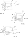
FIGS. 3a -2g, another sequence of trim and tilt of adrive unit 3 according to an example is shown. InFIG. 3a , thedrive unit 3 is in the lowered position LP, wherein thetrim arrangement 7 is trimming thedrive unit 3 to be in a neutral trim angle. Thetrim arrangement 7 is trimming thedrive unit 3. Theconnection part 10 of thetrim arrangement 7 is geometrically engaged with thetrim arrangement lock 8 inside the range of trim angles. In the example, theconnection part 10 is a slot or recess arranged in an end of thetrim arrangement 7 and thetrim arrangement lock 8 is a projection arranged on thedrive unit 3. InFIG. 3b , thedrive unit 3 is still in the lowered position LP, wherein thetrim arrangement 7 is trimming thedrive unit 3 to be in a negative trim angle. Thetrim arrangement 7 is trimming thedrive unit 3 about the pivot j oint. Thelinear actuator 7 is pulling thedrive unit 3 towards thetransom bracket 2 whereby the drive unit is being trimmed to the negative trim angle. Theconnection part 10 of thetrim arrangement 7 is geometrically still engaged with thetrim arrangement lock 8 inside the range of trim angles. - Compared to
FIG. 3b , thedrive unit 3 inFIG. 3c is trimmed to a positive trim angle by thetrim arrangement 7. Thedrive unit 3 is still in the lowered position LP. Thetrim arrangement 7 is trimming thedrive unit 3 about the pivot joint. Thelinear actuator 7 is pushing thedrive unit 3 away thetransom bracket 2 whereby thedrive unit 3 is being trimmed to the positive trim angle. Theconnection part 10 of thetrim arrangement 7 is geometrically is still engaged with thetrim arrangement lock 8 inside the range of trim angles. - Compared to
FIG. 3c , thedrive unit 3 inFIG. 3d is trimmed to a higher positive trim angle by thetrim arrangement 7. Thedrive unit 3 is still in the lowered position LP. Thetrim arrangement 7 is trimming thedrive unit 3 about the pivot j oint. Thelinear actuator 7 is pushing thedrive unit 3 further away thetransom bracket 2 whereby the drive unit is being trimmed to the positive trim angle about thepivot joint 6. Theconnection part 10 of thetrim arrangement 7 is geometrically still engaged with thetrim arrangement lock 8 inside the range of trim angles but thedrive unit 3 is inFIG. 3d very close to be outside the range of trim angles whereby theconnection part 10 and thetrim arrangement lock 8 are disengaged. - In
FIGS. 3e-3g , thedrive unit 3 is outside the range of trim angles. The connectingpart 10 of thelinear actuator 7 is being disengaged from thetrim arrangement lock 8 inFIG. 3e , whereby thelinear actuator 7 is not trimming thedrive unit 3. The tilt arrangement is configured to rotate thedrive unit 3 further about the pivot joint. InFIG. 2f , thedrive unit 3 has been tilted further up towards the raised position RP by the tilt arrangement is rotating thedrive unit 3 further about the pivot j oint. In the example thetrim arrangement 7 has been retracted towards thetransom bracket 2. InFIG. 3g , thedrive unit 3 is in the raised position RP. - The
trim arrangement lock 8 is configured to receive theconnection part 10 or theconnection part 10 is configured to receive thetrim arrangement lock 8 inside the range of trim angles and otherwise being disengaged. In addition, thetrim arrangement lock 8 may be configured to receive theconnection part 10 of the lineartrim actuator 7 or is configured to engage theconnection part 10. - The
trim arrangement lock 8 may comprise a receptacle, a slot, a recess, a bended member, a U-formed member, an inverted U-formed member, a helically or spirally formed member, or similar, when being configured to receive the connectingpart 10. - The
trim arrangement lock 8 may have an inlet through which the connectingpart 10 can enter or leave outside the range of trim angles and a face being configured to maintain theconnection part 10 in thetrim arrangement lock 8 inside the range of trim angles. The inlet may taper so as assisting the connectingpart 10 in enter and leaving thetrim arrangement lock 8. - Moreover, the connecting
part 10 may comprise a geometrical shape configured to engage thetrim arrangement lock 8, such as a projection, a spherical member, a knob, a recess, a slot or similar. Thetrim arrangement lock 8 may comprise a projection, a spherical member, a knob, or similar when being configured to engage the connecting part. - Furthermore, the
trim arrangement lock 8 may be made of a rigid material, such as metal. - In
FIG. 4 , thetrim arrangement 7 is spiral-formed and comprises a rotatory actuator or motor 15. The rotatory motor 15 is configured to rotate the spiral-formedtrim arrangement 7 in both directions so as the drive unit may be trimmed within the range of trim angles. Thetrim arrangement 7 also comprises a spiral-formedtrack 16. In the example, thetrim arrangement lock 8 is configured to be guided in the spiral-formedtrack 16 within the range of trim angels and thereby being connected with the trim arrangement. Thetrim arrangement 7 is arranged on the transom bracket and thetrim arrangement lock 8 is arranged on thedrive unit 3. As thedrive unit 3 is being pivoted outside the range of the trim angles thetrim arrangement lock 8 is moved out spiral-formedtrack 16 and thereby disconnected so that thedrive unit 3 may be tilted. In another example, the spiral-formedtrim arrangement 7 may be arranged on thedrive unit 3 and thetrim arrangement lock 8 is arranged on the transom bracket. - In addition, the
trim arrangement 7 may comprise a plurality of linear trim actuators or rotatory trim actuators and a corresponding number of trim arrangement locks. - In another example, the propulsion system may comprise a kick up function.
- The present disclosure also relates to a
marine vessel 100 comprising a transom and apropulsion system 1 as described above. - The present disclosure also relates to a method for trimming and tilting a
drive unit 3 of apropulsion system 1, comprising - arranging a
propulsion system 1 as describe above on amarine vessel 100, - arranging the
drive unit 3 in the lowered position LP, - trimming the
drive unit 3 by thetrim arrangement 7 inside a range of trim angles while thetrim arrangement 7 is connected with thetrim arrangement lock 8, - pivoting the
drive unit 3 outside the range of trim angles so that thetrim arrangement 7 is disconnected from thetrim arrangement lock 8, - tilting the
drive unit 3 to the raised position by thetilt arrangement 4. - In addition, the method may further comprising
- pivoting the
drive unit 3 from the raised position RP by the tilt arrangement towards the lowered position LP, - connecting the
trim arrangement 7 with thetrim arrangement lock 8 when thedrive unit 3 is pivoted to reach inside the range of trim angles, - trimming the
drive unit 3 by thetrim arrangement 7 inside a range of trim angles while thetrim arrangement 7 is connected with thetrim arrangement lock 8. - Certain aspects and variants of the disclosure are set forth in the following examples numbered consecutive below.
- Example 1: A propulsion system (1) for a marine vessel (100), comprising a transom bracket (2) configured to be connected to a transom of the marine vessel, a drive unit (3) being rotatably connected with the transom bracket (2) so as to be pivotable by a tilt arrangement (4) from a lowered position (LP) into a raised position (RP), or vice versa, about a pivot joint (6), and
- a trim arrangement (7) being arranged between the transom bracket (2) and the drive unit (3) to adjust a trim angle of the drive unit (3) when in the lowered position (LP),
- further comprising a trim arrangement lock (8) being arranged to be connected with the trim arrangement (7) for a range of trim angles of the drive unit (3) in the lowered position so as to prevent pivoting of the drive unit (3) by the tilt arrangement (4) inside the range of trim angles, and the trim arrangement lock (8) is arranged to be disconnected from the trim arrangement (8) outside the range of trim angles so as to allow pivoting of the drive unit (3) by the tilt arrangement (4).
- Example 2: The propulsion system (1) of example 1, wherein the trim arrangement (7) comprises at least one linear trim actuator (7) or rotatory trim actuator, the trim actuator has a connection part (10) arranged at an end of the trim actuator.
- Example 3: The propulsion system (1) of example 2, wherein the connection part (10) is arranged at the end opposite the drive unit.
- Example 4: The propulsion system (1) of example 2, wherein the connection part (10) is arranged in the end opposite the transom bracket.
- Example 5: The propulsion system (1) of any of the examples 2-4, wherein an opposite end of the trim actuator (7) compared to the connection part (10) is connected to the transom bracket or the drive unit.
- Example 6: The propulsion system (1) of example 5, wherein the opposite end of the trim actuator (7) is securely fastened to either the transom bracket or the drive unit.
- Example7: The propulsion system (1) of example 6, wherein the opposite end of the trim actuator (7) projects from either the transom bracket or the drive unit in a fixed angle.
- Example 8: The propulsion system (1) of any of the preceding examples, wherein trim arrangement lock (8) is arranged on the drive unit or at the transom bracket.
- Example 9: The propulsion system (1) of example 8, wherein the trim arrangement lock (8) is securely arranged on the drive unit or on the transom bracket.
- Example 10: The propulsion system (1) of any of examples 2-9, wherein the trim arrangement lock (8) is configured to receive the connection part (10) or the connection part (10) is configured to receive the trim arrangement lock inside the range of trim angles and otherwise being disengaged.
- Example 11: The propulsion system (1) of example 10, wherein the trim arrangement lock (8) and the connection part (10) are geometrically engaged inside the range of trim angles and are disengaged outside the range of trim angles.
- Example 12: The propulsion system (1) of any of the preceding examples, wherein the trim arrangement lock (8) or the trim arrangement is configured to be moved along a trajectory of a rotation radius having the pivot joint (6) as a centre.
- Example 13: The propulsion system (1) of any of the preceding examples, wherein the tilt arrangement (4) is configured to follow the rotation of the drive unit (3) inside the range of trim angles.
- Example 14: The propulsion system (1) of any of the preceding examples, wherein the trim arrangement (7) comprises a plurality of linear trim actuators (7) or a plurality of rotatory trim actuators, and a corresponding number of trim arrangement locks (8).
- Example 15: The propulsion system (1) of any of the preceding examples, wherein the tilt arrangement (4) comprises a linear tilt actuator and/or a rotatory actuator or motor.
- Example 16: The propulsion system (1) of any of the preceding examples, wherein the trim arrangement lock (8) is configured to receive the connection part (10) of the trim actuator or is configured to engage the connection part.
- Example 17: The propulsion system (1) of example 16, wherein the trim arrangement lock (8) and the connection part (10) are geometrically connected and/or engaged inside the range of trim angles.
- Example 18: The propulsion system (1) of example 16-17, wherein the trim arrangement lock (8) comprises a receptacle, a slot, a recess, a bended member, a U-formed member, an inverted U-formed member, a helically or spirally formed member, or similar, when being configured to receive the connecting part (10).
- Example 19: The propulsion system (1) of example 18, wherein the trim arrangement lock (8) has an inlet through which the connecting part (10) can enter or leave outside the range of trim angles and a face being configured to maintain the connection part in the trim arrangement lock inside the range of trim angles.
- Example 20: The propulsion system (1) of example 19, wherein the inlet tapers so as assisting the connecting part (10) in enter and leaving the trim arrangement lock (8).
- Example 21: The propulsion system (1) of claim 18-20, wherein the connecting part (10) comprises a geometrical shape configured to engage the trim arrangement lock (8), such as a projection, a spherical member, a knob, or similar.
- Example 22: The propulsion system (1) of example 16-17, wherein the trim arrangement lock (8) comprises a projection, a spherical member, a knob, or similar when being configured to engage the connecting part (10).
- Example 23: The propulsion system (1) of example 22, wherein the connecting part (10) comprises a geometrical shape configured to receive the trim arrangement lock (8), such as a receptacle, a slot, a recess, a bended member, a U-formed member, an inverted U-formed member, a helically or spirally formed member, or similar.
- Example 24: The propulsion system (1) of any of the preceding examples, wherein the trim arrangement lock (8) is made of a rigid material, such as metal.
- Example 25: The propulsion system (1) of any of the preceding examples, wherein the drive unit (3) comprises an electric motor.
- Example 26: The propulsion system (1) of any of the preceding examples, wherein the drive unit (3) is configured to be trimmed by the trim arrangement (7) and titled around the pivot joint (51) by the tilt arrangement (4).
- Example 27: The propulsion system (1) of example 15, wherein the rotation motor is electric, or the linear tilt actuator (4) is a hydraulic cylinder or a pneumatic cylinder.
- Example 28: The propulsion system (1) of example 2, wherein the linear trim actuator (7) is a hydraulic cylinder or a pneumatic cylinder.
- Example 29: The propulsion system (1) of any of the preceding examples, wherein the drive unit (3) comprises one or more propellers.
- Example 30: The propulsion system (1) of example 29, wherein the one or more propellers are configured to push the marine vessel (100) in a forward motion of the marine vessel.
- Example 31: The propulsion system (1) of example 29, wherein the one or more propellers are configured to pull the marine vessel (100) in a forward motion of the marine vessel.
- Example 32: The propulsion system (1) of example 29, wherein the drive unit (3) comprises a first propeller (13a) and a second propeller (13b).
- Example 33: The propulsion system (1) of example 32, wherein the first propeller (13a) is arranged to be counter-rotating compared to the second propeller (13b).
- Example 34: The propulsion system (1) of any of the preceding examples, further comprising a control unit configured to control the trim arrangement (7) and/or the tilt arrangement (4).
- Example 35: The propulsion system (1) of any of the preceding examples, further comprising a kick up function.
- Example 36: The propulsion system (1) of example 1, wherein the trim arrangement (7) comprises a spiral-formed track (16) and a rotatory motor (15) configured to rotate the spiral-formed track (16).
- Example 37: The propulsion system (1) of example 36, wherein the trim arrangement lock (8) is configured to the guided in the spiral-formed track (16) within the range of trim angles.
- Example 38: A marine vessel (100) comprising a transom and a propulsion system (1) of any of the preceding examples.
- Example 39: A method for trimming and tilting a drive unit (3) of a propulsion system (1), comprising
- arranging a propulsion system (1) of any of the examples 1-37 on a marine vessel (100) of example 38,
- arranging the drive unit (3) in the lowered position (LP),
- trimming the drive unit (3) by the trim arrangement (7) inside a range of trim angles while the trim arrangement (7) is connected with the trim arrangement lock (8),
- pivoting the drive unit (3) outside the range of trim angles so that the trim arrangement (7) is disconnected from the trim arrangement lock (8),
- tilting the drive unit (3) to the raised position by the tilt arrangement (4).
- Example 40: A method of example 39, comprising
- pivoting the drive unit (3) from the raised position (RP) by the tilt arrangement (4) towards the lowered position (LP),
- connecting the trim arrangement (7) with the trim arrangement lock (8) when the drive unit (3) is pivoted to reach inside the range of trim angles,
- trimming the drive unit (3) by the trim arrangement (7) inside a range of trim angles while the trim arrangement (7) is connected with the trim arrangement lock (8).
- The terminology used herein is for the purpose of describing particular aspects only and is not intended to be limiting of the disclosure. As used herein, the singular forms "a," "an," and "the" are intended to include the plural forms as well, unless the context clearly indicates otherwise. As used herein, the term "and/or" includes any and all combinations of one or more of the associated listed items. It will be further understood that the terms "comprises," "comprising," "includes," and/or "including" when used herein specify the presence of stated features, integers, actions, steps, operations, elements, and/or components, but do not preclude the presence or addition of one or more other features, integers, actions, steps, operations, elements, components, and/or groups thereof.
- It will be understood that, although the terms first, second, etc., may be used herein to describe various elements, these elements should not be limited by these terms. These terms are only used to distinguish one element from another. For example, a first element could be termed a second element, and, similarly, a second element could be termed a first element without departing from the scope of the present disclosure.
- Relative terms such as "below" or "above" or "upper" or "lower" or "horizontal" or "vertical" may be used herein to describe a relationship of one element to another element as illustrated in the Figures. It will be understood that these terms and those discussed above are intended to encompass different orientations of the device in addition to the orientation depicted in the Figures. It will be understood that when an element is referred to as being "connected" or "coupled" to another element, it can be directly connected or coupled to the other element, or intervening elements may be present. In contrast, when an element is referred to as being "directly connected" or "directly coupled" to another element, there are no intervening elements present.
- Unless otherwise defined, all terms (including technical and scientific terms) used herein have the same meaning as commonly understood by one of ordinary skill in the art to which this disclosure belongs. It will be further understood that terms used herein should be interpreted as having a meaning consistent with their meaning in the context of this specification and the relevant art and will not be interpreted in an idealized or overly formal sense unless expressly so defined herein.
- It is to be understood that the present disclosure is not limited to the aspects described above and illustrated in the drawings; rather, the skilled person will recognize that many changes and modifications may be made within the scope of the present disclosure and appended claims. In the drawings and specification, there have been disclosed aspects for purposes of illustration only and not for purposes of limitation, the scope of the disclosure being set forth in the following claims.
Claims (15)
- A propulsion system (1) for a marine vessel (100), comprisinga transom bracket (2) configured to be connected to a transom of the marine vessel,a drive unit (3) being rotatably connected with the transom bracket (2) so as to be pivotable by a tilt arrangement (4) from a lowered position (LP) into a raised position (RP), or vice versa, about a pivot joint (6), anda trim arrangement (7) being arranged between the transom bracket (2) and the drive unit (3) to adjust a trim angle of the drive unit (3) when in the lowered position (LP),further comprising a trim arrangement lock (8) being arranged to be connected with the trim arrangement (7) for a range of trim angles of the drive unit (4) in the lowered position (LP) so as to prevent pivoting of the drive unit (3) by the tilt arrangement (4) inside the range of trim angles, and the trim arrangement lock (8) is configured to be disconnected from the trim arrangement (7) outside the range of trim angles so as to allow pivoting of the drive unit by the tilt arrangement (4).
- The propulsion system (1) of claim 1, wherein the trim arrangement (7) comprises at least one linear trim actuator (7), the trim actuator has a connection part (10) arranged at an end of the trim actuator.
- The propulsion system (1) of claim 2, wherein the connection part (10) is arranged at the end opposite the drive unit, or the connection part (10) is arranged in the end opposite the transom bracket (2).
- The propulsion system (1) of any of the claims 2-3, wherein an opposite end of the trim actuator (7) compared to the connection part (10) is connected to the transom bracket or the drive unit.
- The propulsion system (1) of claim 4, wherein the opposite end of the trim actuator (7) is securely fastened to either the transom bracket or the drive unit.
- The propulsion system (1) of any of the claims 1-5, wherein trim arrangement lock (8) is arranged on the drive unit or at the transom bracket.
- The propulsion system (1) of any of claims 2-6, wherein the trim arrangement lock (8) is configured to receive the connection part (10) or the connection part (10) is configured to receive the trim arrangement lock (8) inside the range of trim angles and otherwise being disengaged.
- The propulsion system (1) of claim 7, wherein the trim arrangement lock (8) and the connection part (10) are geometrically engaged inside the range of trim angles and are disengaged outside the range of trim angles.
- The propulsion system (1) of any of the claims 1-8, wherein the trim arrangement lock (8) or the trim arrangement is configured to be moved along a trajectory of a rotation radius having the pivot joint (6) as a centre.
- The propulsion system (1) of any of the claims 2-9, wherein the trim arrangement lock (8) is configured to receive the connection part (10) of the trim actuator or is configured to engage the connection part.
- The propulsion system (1) of claim 10, wherein the trim arrangement lock (8) and the connection part (10) are geometrically connected and/or engaged inside the range of trim angles.
- The propulsion system (1) of claim 10 and/or 11, wherein the trim arrangement lock (8) comprises a receptacle, a slot, a recess, a bended member, a U-formed member, an inverted U-formed member, a helically or spirally formed member, or similar, when being configured to receive the connection part.
- The propulsion system (1) of claim 12, wherein the trim arrangement lock (8) has an inlet through which the connecting part (10) can enter or leave outside the range of trim angles and a face being configured to maintain the connection part in the trim arrangement lock inside the range of trim angles.
- A marine vessel (100) comprising a transom and a propulsion system (1) of any of the claims 1-13.
- A method for trimming and tilting a drive unit (3) of a propulsion system (1), comprising- arranging a propulsion system (1) of any of the claims 1-13 on a marine vessel (100) of claim 14,- arranging the drive unit (3) in the lowered position (LP),- trimming the drive unit (3) by the trim arrangement (7) inside a range of trim angles while the trim arrangement is connected with the trim arrangement lock (8),- pivoting the drive unit (3) outside the range of trim angles so that the trim arrangement (7) is disconnected from the trim arrangement lock (8),- tilting the drive unit to the raised position by the tilt arrangement (4).
Applications Claiming Priority (1)
| Application Number | Priority Date | Filing Date | Title |
|---|---|---|---|
| SE2350446A SE2350446A1 (en) | 2023-04-14 | 2023-04-14 | Propulsion system for a marine vessel |
Publications (1)
| Publication Number | Publication Date |
|---|---|
| EP4458663A1 true EP4458663A1 (en) | 2024-11-06 |
Family
ID=90730098
Family Applications (1)
| Application Number | Title | Priority Date | Filing Date |
|---|---|---|---|
| EP24169838.0A Pending EP4458663A1 (en) | 2023-04-14 | 2024-04-12 | Propulsion system for a marine vessel |
Country Status (4)
| Country | Link |
|---|---|
| US (1) | US20240343369A1 (en) |
| EP (1) | EP4458663A1 (en) |
| CN (1) | CN118790451A (en) |
| SE (1) | SE2350446A1 (en) |
Citations (3)
| Publication number | Priority date | Publication date | Assignee | Title |
|---|---|---|---|---|
| US4362513A (en) * | 1980-07-28 | 1982-12-07 | Outboard Marine Corporation | Dual pivot outboard motor with trim and tilt toggle linkage |
| US5151058A (en) * | 1990-04-20 | 1992-09-29 | Nissan Motor Co., Ltd. | Supporting device for outboard motor |
| US20170355432A1 (en) * | 2016-06-14 | 2017-12-14 | Yamaha Hatsudoki Kabushiki Kaisha | Outboard motor and outboard motor movement mechanism |
Family Cites Families (4)
| Publication number | Priority date | Publication date | Assignee | Title |
|---|---|---|---|---|
| US3683841A (en) * | 1970-05-15 | 1972-08-15 | Schattel Of America Inc | Lift and swinging device for a steerable propeller |
| US4086869A (en) * | 1977-02-07 | 1978-05-02 | James Edward Woodruff | Boat trim adjusting apparatus |
| US4472148A (en) * | 1982-07-19 | 1984-09-18 | Brunswick Corporation | Tilt mechanism for outboard motors |
| US10933963B2 (en) * | 2017-09-01 | 2021-03-02 | Brp Us Inc. | Method for controlling a trim-tilt angle of a marine propulsion unit |
-
2023
- 2023-04-14 SE SE2350446A patent/SE2350446A1/en not_active Application Discontinuation
-
2024
- 2024-04-11 US US18/632,850 patent/US20240343369A1/en active Pending
- 2024-04-12 EP EP24169838.0A patent/EP4458663A1/en active Pending
- 2024-04-12 CN CN202410442157.3A patent/CN118790451A/en active Pending
Patent Citations (3)
| Publication number | Priority date | Publication date | Assignee | Title |
|---|---|---|---|---|
| US4362513A (en) * | 1980-07-28 | 1982-12-07 | Outboard Marine Corporation | Dual pivot outboard motor with trim and tilt toggle linkage |
| US5151058A (en) * | 1990-04-20 | 1992-09-29 | Nissan Motor Co., Ltd. | Supporting device for outboard motor |
| US20170355432A1 (en) * | 2016-06-14 | 2017-12-14 | Yamaha Hatsudoki Kabushiki Kaisha | Outboard motor and outboard motor movement mechanism |
Also Published As
| Publication number | Publication date |
|---|---|
| SE2350446A1 (en) | 2024-10-15 |
| US20240343369A1 (en) | 2024-10-17 |
| CN118790451A (en) | 2024-10-18 |
Similar Documents
| Publication | Publication Date | Title |
|---|---|---|
| US8622777B1 (en) | Systems and methods for controlling trim and maneuvering a marine vessel | |
| US9434460B1 (en) | Marine vessels and systems for laterally maneuvering marine vessels | |
| EP1777153B1 (en) | Marine vessel and marine drive combination | |
| US8777681B1 (en) | Systems and methods for maneuvering a marine vessel | |
| EP1208035B1 (en) | Design for tugboat | |
| US11208190B1 (en) | Stern drives having breakaway lower gearcase | |
| US20240343374A1 (en) | Watersport propulsion system for a marine watersport vessel | |
| US20240343369A1 (en) | Propulsion system for a marine vessel | |
| JP2024171008A (en) | Ship operation control device | |
| EP4574645B1 (en) | Marine propulsion control system | |
| CN1032300C (en) | propulsion device for ship | |
| US20240343368A1 (en) | Propulsion system for a marine vessel | |
| EP4450382A1 (en) | Propulsion system for a marine vessel | |
| EP4169831A1 (en) | A set of parts for marine vessel propulsion assemblies | |
| US5626502A (en) | Power steering adapter for outboard powerheads of various size | |
| EP4461634A1 (en) | A propulsion system with a raisable linear actuator | |
| US20250187711A1 (en) | Propulsion system | |
| US20250074568A1 (en) | Marine propulsion system | |
| US20240343367A1 (en) | Marine propulsion system with a movable swim platform | |
| EP4603377A2 (en) | Joystick for controlling marine propulsion | |
| JP2025036309A (en) | Ship Propulsion Control System | |
| US20240343365A1 (en) | Propulsion system for a marine vessel and a use of a slip clutch assembly | |
| US20240343375A1 (en) | Propulsion system for a marine vessel | |
| US20260131878A1 (en) | Jet propulsion system and jet propulsion watercraft | |
| EP4671113A1 (en) | METHOD FOR PERFORMING AN EMERGENCY STOP OF A WATERCRAFT, CONTROL UNIT AND WATERCRAFT |
Legal Events
| Date | Code | Title | Description |
|---|---|---|---|
| PUAI | Public reference made under article 153(3) epc to a published international application that has entered the european phase |
Free format text: ORIGINAL CODE: 0009012 |
|
| STAA | Information on the status of an ep patent application or granted ep patent |
Free format text: STATUS: THE APPLICATION HAS BEEN PUBLISHED |
|
| AK | Designated contracting states |
Kind code of ref document: A1 Designated state(s): AL AT BE BG CH CY CZ DE DK EE ES FI FR GB GR HR HU IE IS IT LI LT LU LV MC ME MK MT NL NO PL PT RO RS SE SI SK SM TR |
|
| STAA | Information on the status of an ep patent application or granted ep patent |
Free format text: STATUS: REQUEST FOR EXAMINATION WAS MADE |
|
| 17P | Request for examination filed |
Effective date: 20250422 |