EP4458659A1 - An angularly positioned marine propeller combination and a method of operating a marine propeller combination - Google Patents
An angularly positioned marine propeller combination and a method of operating a marine propeller combination Download PDFInfo
- Publication number
- EP4458659A1 EP4458659A1 EP23171868.5A EP23171868A EP4458659A1 EP 4458659 A1 EP4458659 A1 EP 4458659A1 EP 23171868 A EP23171868 A EP 23171868A EP 4458659 A1 EP4458659 A1 EP 4458659A1
- Authority
- EP
- European Patent Office
- Prior art keywords
- propeller
- marine
- shaft
- blades
- combination
- Prior art date
- Legal status (The legal status is an assumption and is not a legal conclusion. Google has not performed a legal analysis and makes no representation as to the accuracy of the status listed.)
- Granted
Links
Images

Classifications
-
- B—PERFORMING OPERATIONS; TRANSPORTING
- B63—SHIPS OR OTHER WATERBORNE VESSELS; RELATED EQUIPMENT
- B63H—MARINE PROPULSION OR STEERING
- B63H1/00—Propulsive elements directly acting on water
- B63H1/02—Propulsive elements directly acting on water of rotary type
- B63H1/12—Propulsive elements directly acting on water of rotary type with rotation axis substantially in propulsive direction
- B63H1/14—Propellers
- B63H1/20—Hubs; Blade connections
-
- B—PERFORMING OPERATIONS; TRANSPORTING
- B63—SHIPS OR OTHER WATERBORNE VESSELS; RELATED EQUIPMENT
- B63H—MARINE PROPULSION OR STEERING
- B63H5/00—Arrangements on vessels of propulsion elements directly acting on water
- B63H5/07—Arrangements on vessels of propulsion elements directly acting on water of propellers
- B63H5/08—Arrangements on vessels of propulsion elements directly acting on water of propellers of more than one propeller
- B63H5/10—Arrangements on vessels of propulsion elements directly acting on water of propellers of more than one propeller of coaxial type, e.g. of counter-rotative type
-
- B—PERFORMING OPERATIONS; TRANSPORTING
- B63—SHIPS OR OTHER WATERBORNE VESSELS; RELATED EQUIPMENT
- B63H—MARINE PROPULSION OR STEERING
- B63H23/00—Transmitting power from propulsion power plant to propulsive elements
- B63H23/02—Transmitting power from propulsion power plant to propulsive elements with mechanical gearing
-
- B—PERFORMING OPERATIONS; TRANSPORTING
- B63—SHIPS OR OTHER WATERBORNE VESSELS; RELATED EQUIPMENT
- B63H—MARINE PROPULSION OR STEERING
- B63H5/00—Arrangements on vessels of propulsion elements directly acting on water
- B63H5/07—Arrangements on vessels of propulsion elements directly acting on water of propellers
- B63H5/08—Arrangements on vessels of propulsion elements directly acting on water of propellers of more than one propeller
-
- B—PERFORMING OPERATIONS; TRANSPORTING
- B63—SHIPS OR OTHER WATERBORNE VESSELS; RELATED EQUIPMENT
- B63H—MARINE PROPULSION OR STEERING
- B63H5/00—Arrangements on vessels of propulsion elements directly acting on water
- B63H5/07—Arrangements on vessels of propulsion elements directly acting on water of propellers
- B63H5/08—Arrangements on vessels of propulsion elements directly acting on water of propellers of more than one propeller
- B63H5/10—Arrangements on vessels of propulsion elements directly acting on water of propellers of more than one propeller of coaxial type, e.g. of counter-rotative type
- B63H2005/106—Arrangements on vessels of propulsion elements directly acting on water of propellers of more than one propeller of coaxial type, e.g. of counter-rotative type with drive shafts of second or further propellers co-axially passing through hub of first propeller, e.g. counter-rotating tandem propellers with co-axial drive shafts
Definitions
- the disclosure relates generally to marine propulsion.
- the disclosure relates to a marine propeller combination for a marine propulsion unit, a marine propulsion unit, a marine vessel, and a method of operating a marine propeller combination.
- the disclosure can be applied to marine vessels, such as water crafts, motorboats, work boats, sport vessels, sailboats, boats, ships, among other vessel types.
- the disclosure may be described with respect to a particular vessel, the disclosure is not restricted to any particular vessel.
- Marine propulsion units are used to propel marine vessels in water. Some marine propulsion units comprise one or more propellers. In some examples, two concentric propellers may be arranged to rotate in opposite directions. The latter solution brings a number of benefits, such as high efficiency and good acceleration.
- a marine propeller combination for a marine propulsion unit, the marine propeller combination comprising a first propeller and a second propeller arranged to rotate simultaneously in opposite directions about a common rotational axis.
- the marine propeller combination is configured such that the first and second propellers are angularly positioned such that during one revolution one of the blades of the first propeller is aligned with a drive leg of the marine propulsion unit when a blade gap of the second propeller is aligned with the drive leg, or one of the blades of the first propeller is aligned with the drive leg when one of the blades of the second propeller is aligned with the drive leg.
- the first aspect of the disclosure may seek to optimise the operation of a marine propeller combination.
- a technical benefit may include higher efficiency and reduced vibrations and noise. Said benefits may also be valid should the marine propeller combination be used for power generation, i.e. for generating electric power from water that moves in relation to the marine propeller combination.
- first and second propellers being angularly positioned may be meant that the first and second propellers are deliberately, consciously or purposively angularly positioned. I.e. that the respective angular position of the propellers with respect to the drive leg is not arbitrary, but is to the contrary deliberately set or selected.
- one of the blades of the first propeller is aligned with the drive leg when a blade gap of the second propeller is aligned with the drive leg in a forward drive configuration of the marine propeller combination.
- one of the blades of the first propeller is aligned with the drive leg when one of the blades of the second propeller is aligned with the drive leg in a rearward drive configuration of the marine propeller combination.
- the number of propeller blades of the first propeller is three and the number of propeller blades of the second propeller is four.
- the number of propeller blades of the first propeller is four and the number of propeller blades of the second propeller is four, and the first and second propellers are angularly positioned such that when two of the blades of the first or second propeller are vertically positioned, two of the blades of the other propeller are positioned angularly offset by 30 to 60 degrees with respect to the vertical.
- the first propeller is adapted to be mounted on a first shaft of the marine propulsion unit and the second propeller is adapted to be mounted on a second shaft of the marine propulsion unit
- the first propeller comprises a first propeller position feature for angularly mounting the first propeller on the first shaft
- the second propeller comprises a second propeller position feature for angularly mounting the second propeller on the second shaft.
- the first propeller position feature is a visual marking or shape irregularity and the second propeller position feature is a visual marking or shape irregularity.
- the first propeller position feature is a shape irregularity in an internal spline pattern of the first propeller and/or the second propeller position feature is a shape irregularity in an internal spline pattern of the second propeller.
- a technical benefit may include that mounting in a favourable position is ensured.
- a marine propulsion unit comprising the above-described marine propeller combination and a drive leg supporting the marine propeller combination.
- the marine propulsion unit comprises a first shaft for the first propeller and a second shaft for the second propeller.
- the first shaft and the second shaft are arranged to rotate simultaneously in opposite directions at the same speed.
- a marine propulsion unit for the above-described marine propeller combination, the marine propulsion unit comprising a drive leg and a first shaft for the first propeller and a second shaft for the second propeller.
- the first shaft comprises a first shaft position feature and the first propeller comprises a first propeller position feature, said features being provided for angularly mounting the first propeller on the first shaft
- the second shaft comprises a second position feature and the second propeller comprises a second propeller position feature, said features being provided for angularly mounting the second propeller on the second shaft.
- a marine vessel comprising the above-described marine propeller combination or the above-described marine propulsion units,
- a method of operating a marine propeller combination for a marine propulsion unit comprising a drive leg supporting the marine propeller combination, the marine propeller combination comprising a first propeller and a second propeller arranged to rotate simultaneously in opposite directions about a common rotational axis, the method comprising angularly positioning the first propeller and the second propeller such that during one revolution one of the blades of the first propeller is aligned with the drive leg while a blade gap of the second propeller is aligned with the drive leg, or one of the blades of the first propeller is aligned with the drive leg while one of the blades of the second propeller is aligned with the drive leg.
- a marine propeller comprising a number of propeller blades and an internal spline pattern, wherein the internal spline pattern comprises a shape irregularity for angularly positioning the marine propeller.
- the shape irregularity may be angularly aligned with respect to the propeller blades and may be a lacking spline, or a filled spline, in the internal spline pattern.
- the inventive concept of the present disclosure is based on the realisation that in forward drive (pulling) counter-rotating propellers, a first or front propeller faces a uniform flow whereas the rear propeller faces a non-uniform flow. Further, the counter-rotating propellers create a downstream propeller wash that is dependent on the angular position between the front and rear propellers.
- the propeller wash impacts a drive leg, and the angular positioning between the front and rear propeller may according to the inventive concept be set to reduce the appendage drag.
- the propellers face a wake generated by the drive leg, i.e. a non-uniform flow.
- the wake may create a fluctuation in the thrust and torque of the propellers, and the angular positioning between the front and rear propeller may, according to the inventive concept, be set to reduce torque and thrust fluctuations.
- the inventive concept involves angularly positioning counter-rotating propellers with respect to a drive leg to optimise propulsion performance.
- the optimisation may involve reduced vibrations and/or increased efficiency.
- FIG. 1 to 4 illustrate a marine propeller combination and a marine propulsion unit 1.
- FIG. 2 and 4 also illustrate a marine vessel 50.
- the marine propeller combination comprises a first propeller 10 and a second propeller 20 arranged to rotate simultaneously in opposite directions about a common rotational axis A.
- the marine propulsion unit may be referred to as a coaxial counter-rotating (or contra-rotating) marine propulsion system.
- FIG. 5 and 6 illustrate marine propellers 10, 20 each comprising a number of propeller blades and an internal spline pattern, wherein the internal spline pattern comprises a shape irregularity 10f, 20f for angularly positioning the marine propeller 10, 20.
- the marine propeller combination is configured such that the first and second propellers 10, 20 are angularly positioned such that during one revolution, one of the blades of the first propeller 10 is aligned with a drive leg 2 of the marine propulsion unit 1 when a blade gap of the second propeller 20 is aligned with the drive leg 2.
- this angular positioning is adapted for a forward drive configuration of the marine propeller combination, i.e. where the marine propeller combination is positioned on the bow side of the drive leg 2.
- a forward drive configuration may be referred to as a pulling configuration.
- the marine propeller combination is configured such that one of the blades of the first propeller 10 is aligned with the drive leg 2 when one of the blades of the second propeller 20 is aligned with the drive leg 2.
- this angular positioning is adapted for a rearward drive configuration of the marine propeller combination, i.e. where the marine propeller combination is positioned on the stern side of the drive leg 2.
- a rearward drive configuration may be referred to as a pushing configuration.
- the angular positions of the first and second propellers 10, 20 are deliberately selected in relation to the drive leg 2 of the marine propulsion unit 1.
- the blades of the propellers are deliberately set to either pass the drive leg 2 concurrently or to not pass the drive leg concurrently.
- the blades of the propellers are set to pass the drive leg concurrently.
- the blades of the propellers are set to not pass the drive leg concurrently.
- the blades of the first propeller 10 and second propeller 20 are arranged to pass the drive leg 2 simultaneously, or are arranged to pass the drive leg 2 separately.
- FIG. 1 and 2 disclose a first or front propeller 10 and a second or rear propeller 20.
- the first propeller 10 is located on the bow side of the second propeller 20.
- the first propeller 10 is located in front of the second propeller 20 when the propellers 10, 20 travel through the water.
- the first propeller may rotate clockwise and the second propeller may rotate counter-clockwise, as is indicated by the curved arrows is FIG. 1 .
- FIG. 1 shows the first propeller 10 angularly positioned such that one blade is aligned with, i.e. is positioned essentially straight in front of, the drive leg 2.
- said blade is aligned with the portion of the drive leg 2 that is located between the propellers 10, 20 and the vessel 50, i.e. the portion above the propellers 10, 20.
- the drive leg 2 also comprises a portion that is located on the distal side of the propellers 10, 20, i.e. below the propellers. As is shown, the portion of the drive leg 2 that is located between the propellers 10, 20 and the vessel 50 is substantially wider than the portion of the drive leg 2 that is located on the distal side of the propellers 10, 20. The latter portion is optional.
- the present disclosure relates to positioning the propellers with respect to the portion of the drive leg that is located between the propellers 10, 20 and the vessel.
- first propeller 10 when the first propeller 10 is angularly positioned such that one blade is aligned with the drive leg 2, said blade is vertically positioned, or is oriented vertically, or is vertical, as is illustrated in FIG. 1 .
- said bade points essentially straight upwards.
- a blade gap of the second propeller 20 is aligned with the drive leg 2. In other words, no propeller blade of the second propeller is aligned with the drive leg 2.
- the angular positioning of FIG. 1 and 2 is adapted for a forward drive (pulling) configuration of the marine propeller combination, i.e. where the marine propeller combination is positioned on the bow side of the drive leg 2.
- one of the blades of the first propeller 10 may be aligned with the drive leg 2 when a blade gap of the second propeller 20 is aligned with the drive leg 2 in a forward drive configuration of the marine propeller combination.
- the phrase "aligned with” does not mean that there needs to be a perfect alignment between for example a blade of the first propeller 10 and the drive leg 2.
- one blade of the first propeller 10 is oriented vertically and is exactly parallel to the drive leg 2.
- the blades of the second propeller 20 that form the blade gap are exactly symmetrically positioned with respect to the drive leg 2.
- the inventive concept of the present disclosure does not prescribe any perfect alignment. It is believed that deviations of up to 1 degree, 2 degrees or up to 5 degrees may be acceptable.
- one of the blades of the first propeller 10 may be aligned with the drive leg 2 when one of the blades of the second propeller 20 is aligned with the drive leg 2 in a rearward drive configuration of the marine propeller combination.
- one of the blades of both propellers point essentially straight upwards.
- first propeller 10 and the second propeller 20 may have the same number of blades.
- the first propeller 10 may have two to six blades and the second propeller 20 may have two to six blades.
- the first propeller 10 and the second propeller 20 do not have the same number of propeller blades.
- the number of propeller blades of the first propeller 10 is three and the number of propeller blades of the second propeller 20 is four.
- the positioning may be such that the second propeller 20 may be angularly positioned with two of the blades being vertical and the other two being horizontal while the blades of the second propeller 10 are positioned offset by 30 to 60 degrees with respect to the vertical.
- the number of propeller blades of the first propeller 10 is four and the number of propeller blades of the second propeller 20 is four.
- the first and second propellers 10, 20 may then be angularly positioned such that when two of the blades of the first or second propeller 10, 20 are vertically oriented, two of the blades of the other propeller 10, 20 are positioned angularly offset by 30 to 60 degrees with respect to the vertical.
- the blades of the propellers 10, 20 are set to not pass a drive leg concurrently, the drive leg extending vertically upwards from the propellers 10, 20.
- the first and second propellers 10, 20 may instead not be angularly offset.
- FIG. 7 and 8 show the distal ends of a first shaft 3a and a second shaft 3b of the marine propulsion unit 1, the shafts 3a, 3b being jointly denoted with the reference number 3 in FIG. 2 .
- the first propeller 10 FIG. 6
- the first shaft 3a may be referred to as a front shaft or an inner shaft.
- the second propeller 20 may be adapted to be mounted on the second shaft 3b of the marine propulsion unit 1.
- the second shaft 3b may be referred to as a rear shaft or an outer shaft.
- the first propeller 10 may comprise a first propeller position feature 10f for angularly mounting the first propeller 10 on the first shaft 3a.
- the first propeller position feature 10f may be a visual marking or, as illustrated herein, a shape irregularity on the first propeller 10.
- the visual marking may be a painted mark or a sticker.
- the first propeller position feature 10f is a shape irregularity in an internal spline pattern of the first propeller 10. More precisely, as is shown in FIG. 6 , one spline is filled. Alternatively, in undepicted examples one spline may be lacking.
- the spline pattern may be said to comprise a number of circumferential teeth.
- a filled spline as is shown in FIG. 6 , corresponds to a filled gap between two neighbouring teeth.
- a lacking spline corresponds to one lacking tooth.
- the spline patterns disclosed herein extend at an angle to the longitudinal propeller axes.
- the spline patterns are thus helical.
- the spline patterns may be straight, i.e. extend parallel to longitudinal propeller axes.
- the second propeller 20 may comprise a second propeller position feature 20f for angularly mounting the second propeller 20 on the second shaft 3b.
- the second propeller position feature 20f may be a visual marking or, as illustrated herein, a shape irregularity on the second propeller 20.
- the present second propeller position feature 20f is a shape irregularity in the internal spline pattern of the second propeller 20, more precisely a filled spline. In undepicted examples, one spline may instead be lacking.
- the second propeller 20 may comprise a second propeller position feature 20f for angularly mounting the second propeller 20 on the second shaft 3b.
- the second propeller 20 may more easily be positioned at a desired rotational angle with respect to the second shaft 3b. This may alternatively be expressed as the second propeller position feature 20f facilitating setting the desired angle of the propeller blades with respect to the second shaft 3b.
- the first propeller position feature 10f is adapted for a first shaft position feature 3af and the second propeller position feature 20f is adapted for a second shaft position feature 3bf.
- the first shaft position feature 3af is a lacking external spline and the first propeller position feature 10f is a filled internal spline.
- the reverse situation is also possible. Such a solution may avoid, or even make impossible, that the propeller is incorrectly rotationally positioned on the shaft.
- one or both propellers 10, 20 or shafts 3a, 3b may comprise regular uniform spline patterns and the deliberate positioning of the propellers 10, 20 with respect to the shafts 3a, 3b may be obtained by a skilled operator or through use of instructions that provide accurate guidance.
- one or both shafts 3a, 3b are correctly angularly oriented with regards to a drive, such as gears, at the proximal (not shown in detail) ends of one or both shafts 3a, 3b
- one or both shafts may comprise undepicted shaft gear position features.
- Such shaft gear position features may facilitate, or ensure, that a shaft is correctly angularly oriented with regards to the drive.
- the first shaft 3a and the second shaft 3b may be arranged to rotate simultaneously in opposite directions at the same speed, or rpm.
- the propellers 10, 20 may be arranged to rotate simultaneously in opposite directions at the same speed.
- the shafts 3a, 3b may both be driven by one and the same bevel gear.
- the disclosure does not exclude that the first and second shafts 3a, 3b may be arranged to rotate simultaneously in opposite directions at different speeds.
- the first shaft 3a (and the first propeller 10) may be arranged to rotate independently from the second shaft 3b (and second propeller 20).
- the inventive concept may in the latter case be utilised in situations when the shafts 3a, 3b are driven to rotate simultaneously in opposite directions at the same speed. In such a case, there may be provided sensors or other means for registering the angular positions of the shafts 3a, 3b and/or the propellers 10, 20.
- FIG. 9 illustrates a method 100 of operating a marine propeller combination for a marine propulsion unit 1 comprising a drive leg 2 supporting the marine propeller combination.
- the marine propeller combination may be of the type described herein.
- the marine propeller combination may comprise a first propeller 10 and a second propeller 20 arranged to rotate simultaneously in opposite directions about a common rotational axis A, the method 100 comprising angularly positioning 130 the first propeller 10 and the second propeller 20 such that during one revolution one of the blades of the first propeller 10 is aligned with the drive leg 2 while a blade gap of the second propeller 20 is aligned with the drive leg 2, or one of the blades of the first propeller 10 is aligned with the drive leg 2 while one of the blades of the second propeller 20 is aligned with the drive leg 2.
- the method 100 may comprise rotating 110 the first propeller 10 and the second propeller 20 at the same speed, or 120 sensing the position of the first propeller 10 and the second propeller 20 in relation to the drive leg 2.
- the drive leg 2 may support, in other words hold, the marine propeller combination.
- the drive leg 2 may support the propellers 10, 20.
- the drive leg may provide power to the propellers 10, 20.
- There may for example be an undepicted drive shaft extending within the drive leg 2.
- the drive leg 2 extends from a vessel 50 to the propellers 10, 20, as disclosed in figures 2 and 4 .
- the drive leg 2 may extend from a main part of a propulsion unit 1 to the propellers 10, 20.
- the main part may be configured to be attached to a transom of a marine vessel.
- the main part may comprise a propulsion motor, such as a combustion engine or an electric propulsion motor, which drives the propellers 10, 20.
- the drive leg 2, or the portion of the drive leg 2, that is referred to herein is during operation located between the propellers and the water surface.
- the drive leg 2, or the portion of the drive leg 2, that is referred to in herein is located above the propellers 10, 20 during operation.
- Relative terms such as “below” or “above” or “upper” or “lower” or “horizontal” or “vertical” may be used herein to describe a relationship of one element to another element as illustrated in the Figures. It will be understood that these terms and those discussed above are intended to encompass different orientations of the device in addition to the orientation depicted in the Figures. It will be understood that when an element is referred to as being “connected” or “coupled” to another element, it can be directly connected or coupled to the other element, or intervening elements may be present. In contrast, when an element is referred to as being “directly connected” or “directly coupled” to another element, there are no intervening elements present.
Landscapes
- Chemical & Material Sciences (AREA)
- Engineering & Computer Science (AREA)
- Combustion & Propulsion (AREA)
- Mechanical Engineering (AREA)
- Ocean & Marine Engineering (AREA)
- Toys (AREA)
- Other Liquid Machine Or Engine Such As Wave Power Use (AREA)
Abstract
Description
- The disclosure relates generally to marine propulsion. In particular aspects, the disclosure relates to a marine propeller combination for a marine propulsion unit, a marine propulsion unit, a marine vessel, and a method of operating a marine propeller combination. The disclosure can be applied to marine vessels, such as water crafts, motorboats, work boats, sport vessels, sailboats, boats, ships, among other vessel types. Although the disclosure may be described with respect to a particular vessel, the disclosure is not restricted to any particular vessel.
- Marine propulsion units are used to propel marine vessels in water. Some marine propulsion units comprise one or more propellers. In some examples, two concentric propellers may be arranged to rotate in opposite directions. The latter solution brings a number of benefits, such as high efficiency and good acceleration.
- According to a first aspect of the disclosure, there is provided a marine propeller combination for a marine propulsion unit, the marine propeller combination comprising a first propeller and a second propeller arranged to rotate simultaneously in opposite directions about a common rotational axis. The marine propeller combination is configured such that the first and second propellers are angularly positioned such that during one revolution one of the blades of the first propeller is aligned with a drive leg of the marine propulsion unit when a blade gap of the second propeller is aligned with the drive leg, or one of the blades of the first propeller is aligned with the drive leg when one of the blades of the second propeller is aligned with the drive leg.
- The first aspect of the disclosure may seek to optimise the operation of a marine propeller combination. A technical benefit may include higher efficiency and reduced vibrations and noise. Said benefits may also be valid should the marine propeller combination be used for power generation, i.e. for generating electric power from water that moves in relation to the marine propeller combination.
- By the first and second propellers being angularly positioned may be meant that the first and second propellers are deliberately, consciously or purposively angularly positioned. I.e. that the respective angular position of the propellers with respect to the drive leg is not arbitrary, but is to the contrary deliberately set or selected.
- Optionally in some examples, including in at least one preferred example, one of the blades of the first propeller is aligned with the drive leg when a blade gap of the second propeller is aligned with the drive leg in a forward drive configuration of the marine propeller combination.
- Optionally in some examples, including in at least one preferred example, one of the blades of the first propeller is aligned with the drive leg when one of the blades of the second propeller is aligned with the drive leg in a rearward drive configuration of the marine propeller combination.
- Optionally in some examples, including in at least one preferred example, the number of propeller blades of the first propeller is three and the number of propeller blades of the second propeller is four.
- Optionally in some examples, including in at least one preferred example, the number of propeller blades of the first propeller is four and the number of propeller blades of the second propeller is four, and the first and second propellers are angularly positioned such that when two of the blades of the first or second propeller are vertically positioned, two of the blades of the other propeller are positioned angularly offset by 30 to 60 degrees with respect to the vertical.
- Optionally in some examples, including in at least one preferred example, the first propeller is adapted to be mounted on a first shaft of the marine propulsion unit and the second propeller is adapted to be mounted on a second shaft of the marine propulsion unit, the first propeller comprises a first propeller position feature for angularly mounting the first propeller on the first shaft, and the second propeller comprises a second propeller position feature for angularly mounting the second propeller on the second shaft. A technical benefit may include that the mounting is facilitated, or that mounting in a favourable position is ensured.
- Optionally in some examples, including in at least one preferred example, the first propeller position feature is a visual marking or shape irregularity and the second propeller position feature is a visual marking or shape irregularity.
- Optionally in some examples, including in at least one preferred example, the first propeller position feature is a shape irregularity in an internal spline pattern of the first propeller and/or the second propeller position feature is a shape irregularity in an internal spline pattern of the second propeller. A technical benefit may include that mounting in a favourable position is ensured.
- According to a second aspect of the disclosure, there is provided a marine propulsion unit comprising the above-described marine propeller combination and a drive leg supporting the marine propeller combination.
- Optionally in some examples, including in at least one preferred example, the marine propulsion unit comprises a first shaft for the first propeller and a second shaft for the second propeller.
- Optionally in some examples, including in at least one preferred example, the first shaft and the second shaft are arranged to rotate simultaneously in opposite directions at the same speed.
- According to a third aspect of the disclosure, there is provided a marine propulsion unit for the above-described marine propeller combination, the marine propulsion unit comprising a drive leg and a first shaft for the first propeller and a second shaft for the second propeller.
- Optionally in some examples, including in at least one preferred example, the first shaft comprises a first shaft position feature and the first propeller comprises a first propeller position feature, said features being provided for angularly mounting the first propeller on the first shaft, and the second shaft comprises a second position feature and the second propeller comprises a second propeller position feature, said features being provided for angularly mounting the second propeller on the second shaft.
- According to a third aspect of the disclosure, there is provided a marine vessel comprising the above-described marine propeller combination or the above-described marine propulsion units,
- According to a fourth aspect of the disclosure, there is provided a method of operating a marine propeller combination for a marine propulsion unit comprising a drive leg supporting the marine propeller combination, the marine propeller combination comprising a first propeller and a second propeller arranged to rotate simultaneously in opposite directions about a common rotational axis, the method comprising angularly positioning the first propeller and the second propeller such that during one revolution one of the blades of the first propeller is aligned with the drive leg while a blade gap of the second propeller is aligned with the drive leg, or one of the blades of the first propeller is aligned with the drive leg while one of the blades of the second propeller is aligned with the drive leg.
- According to a fourth aspect of the disclosure, there is provided a marine propeller comprising a number of propeller blades and an internal spline pattern, wherein the internal spline pattern comprises a shape irregularity for angularly positioning the marine propeller. The shape irregularity may be angularly aligned with respect to the propeller blades and may be a lacking spline, or a filled spline, in the internal spline pattern.
- The benefits, and further possible features, of the second to fourth aspects correspond to those of the first aspect.
- The disclosed aspects, examples (including any preferred examples), and/or accompanying claims may be suitably combined with each other as would be apparent to anyone of ordinary skill in the art. Additional features and advantages are disclosed in the following description, claims, and drawings, and in part will be readily apparent therefrom to those skilled in the art or recognized by practicing the disclosure as described herein.
- Examples are described in more detail below with reference to the appended drawings.
-
FIG. 1 is a stem view of an exemplary forward drive marine propeller combination comprising a first and a second propeller. -
FIG. 2 is a side view of the forward drive marine propeller combination ofFIG. 1 mounted on a marine vessel. -
FIG. 3 is a stem view of an exemplary rearward drive marine propeller combination. -
FIG. 4 is a side view of the rearward drive marine propeller combination ofFIG. 3 mounted on a marine vessel. -
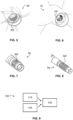
FIG. 5 shows an exemplary second propeller that may form part of the propeller combination ofFIG. 1 . -
FIG. 6 shows an exemplary first propeller that may form part of the propeller combination ofFIG. 1 . -
FIG. 7 shows an exemplary shaft for the second propeller ofFIG. 5 . -
FIG. 8 shows an exemplary shaft for the first propeller ofFIG. 6 . -
FIG. 9 illustrates a method of operating a marine propeller combination. - The detailed description set forth below provides information and examples of the disclosed technology with sufficient detail to enable those skilled in the art to practice the disclosure.
- The inventive concept of the present disclosure is based on the realisation that in forward drive (pulling) counter-rotating propellers, a first or front propeller faces a uniform flow whereas the rear propeller faces a non-uniform flow. Further, the counter-rotating propellers create a downstream propeller wash that is dependent on the angular position between the front and rear propellers. The propeller wash impacts a drive leg, and the angular positioning between the front and rear propeller may according to the inventive concept be set to reduce the appendage drag.
- In a rearward drive (pushing) counter-rotating propellers, the propellers face a wake generated by the drive leg, i.e. a non-uniform flow. The wake may create a fluctuation in the thrust and torque of the propellers, and the angular positioning between the front and rear propeller may, according to the inventive concept, be set to reduce torque and thrust fluctuations.
- The inventive concept involves angularly positioning counter-rotating propellers with respect to a drive leg to optimise propulsion performance. The optimisation may involve reduced vibrations and/or increased efficiency.
-
FIG. 1 to 4 illustrate a marine propeller combination and amarine propulsion unit 1.FIG. 2 and 4 also illustrate amarine vessel 50. - The marine propeller combination comprises a
first propeller 10 and asecond propeller 20 arranged to rotate simultaneously in opposite directions about a common rotational axis A. The marine propulsion unit may be referred to as a coaxial counter-rotating (or contra-rotating) marine propulsion system. -
FIG. 5 and 6 illustratemarine propellers shape irregularity marine propeller - Referring in particular to
FIG. 1 , the marine propeller combination is configured such that the first andsecond propellers first propeller 10 is aligned with adrive leg 2 of themarine propulsion unit 1 when a blade gap of thesecond propeller 20 is aligned with thedrive leg 2. In other words, when one of the blades of thefirst propeller 10 is aligned with thedrive leg 2, no propeller blade of thesecond propeller 20 is aligned with thedrive leg 2. As is shown, this angular positioning is adapted for a forward drive configuration of the marine propeller combination, i.e. where the marine propeller combination is positioned on the bow side of thedrive leg 2. A forward drive configuration may be referred to as a pulling configuration. - Alternatively, referring in particular to
FIG. 3 , the marine propeller combination is configured such that one of the blades of thefirst propeller 10 is aligned with thedrive leg 2 when one of the blades of thesecond propeller 20 is aligned with thedrive leg 2. As is shown, this angular positioning is adapted for a rearward drive configuration of the marine propeller combination, i.e. where the marine propeller combination is positioned on the stern side of thedrive leg 2. A rearward drive configuration may be referred to as a pushing configuration. - Thus, in both cases the angular positions of the first and
second propellers drive leg 2 of themarine propulsion unit 1. The blades of the propellers are deliberately set to either pass thedrive leg 2 concurrently or to not pass the drive leg concurrently. In a rearward drive configuration, the blades of the propellers are set to pass the drive leg concurrently. In a forward drive configuration, the blades of the propellers are set to not pass the drive leg concurrently. - In other words, depending on whether the marine propeller combination is in a rearward or forwards drive configuration, the blades of the
first propeller 10 andsecond propeller 20 are arranged to pass thedrive leg 2 simultaneously, or are arranged to pass thedrive leg 2 separately. - In some more detail,
FIG. 1 and 2 disclose a first orfront propeller 10 and a second orrear propeller 20. Thefirst propeller 10 is located on the bow side of thesecond propeller 20. In other words, thefirst propeller 10 is located in front of thesecond propeller 20 when thepropellers FIG. 1 . - Now,
FIG. 1 shows thefirst propeller 10 angularly positioned such that one blade is aligned with, i.e. is positioned essentially straight in front of, thedrive leg 2. To be precise, said blade is aligned with the portion of thedrive leg 2 that is located between thepropellers vessel 50, i.e. the portion above thepropellers - In the disclosed example, the
drive leg 2 also comprises a portion that is located on the distal side of thepropellers drive leg 2 that is located between thepropellers vessel 50 is substantially wider than the portion of thedrive leg 2 that is located on the distal side of thepropellers - As is to be apprehended, the present disclosure relates to positioning the propellers with respect to the portion of the drive leg that is located between the
propellers - Typically, when the
first propeller 10 is angularly positioned such that one blade is aligned with thedrive leg 2, said blade is vertically positioned, or is oriented vertically, or is vertical, as is illustrated inFIG. 1 . Typically, said bade points essentially straight upwards. - As is further shown in
FIG. 1 , a blade gap of thesecond propeller 20 is aligned with thedrive leg 2. In other words, no propeller blade of the second propeller is aligned with thedrive leg 2. - As is shown, the angular positioning of
FIG. 1 and 2 is adapted for a forward drive (pulling) configuration of the marine propeller combination, i.e. where the marine propeller combination is positioned on the bow side of thedrive leg 2. Thus, as is illustrated, one of the blades of thefirst propeller 10 may be aligned with thedrive leg 2 when a blade gap of thesecond propeller 20 is aligned with thedrive leg 2 in a forward drive configuration of the marine propeller combination. - It is to be apprehended that the phrase "aligned with" does not mean that there needs to be a perfect alignment between for example a blade of the
first propeller 10 and thedrive leg 2. InFIG. 1 , one blade of thefirst propeller 10 is oriented vertically and is exactly parallel to thedrive leg 2. At the same time, the blades of thesecond propeller 20 that form the blade gap are exactly symmetrically positioned with respect to thedrive leg 2. However, the inventive concept of the present disclosure does not prescribe any perfect alignment. It is believed that deviations of up to 1 degree, 2 degrees or up to 5 degrees may be acceptable. - Turning now to
FIG. 3 and 4 , one of the blades of thefirst propeller 10 may be aligned with thedrive leg 2 when one of the blades of thesecond propeller 20 is aligned with thedrive leg 2 in a rearward drive configuration of the marine propeller combination. In the present example, one of the blades of both propellers point essentially straight upwards. - In undepicted embodiments, the
first propeller 10 and thesecond propeller 20 may have the same number of blades. Thefirst propeller 10 may have two to six blades and thesecond propeller 20 may have two to six blades. - In the illustrated examples, the
first propeller 10 and thesecond propeller 20 do not have the same number of propeller blades. - As is shown in
FIG. 1 and 3 (and inFIG. 5 and 6 ), in the present examples the number of propeller blades of thefirst propeller 10 is three and the number of propeller blades of thesecond propeller 20 is four. - Referring again to
FIG. 1 and envisioning that thefirst propeller 10 from the shown orientation has rotated 45 degrees clockwise and the second propeller has rotated 45 degrees counter-clockwise. The positioning may be such that thesecond propeller 20 may be angularly positioned with two of the blades being vertical and the other two being horizontal while the blades of thesecond propeller 10 are positioned offset by 30 to 60 degrees with respect to the vertical. - In an undisclosed example, the number of propeller blades of the
first propeller 10 is four and the number of propeller blades of thesecond propeller 20 is four. In a forward drive configuration, the first andsecond propellers second propeller other propeller propellers propellers second propellers -
FIG. 7 and 8 show the distal ends of afirst shaft 3a and asecond shaft 3b of themarine propulsion unit 1, theshafts reference number 3 inFIG. 2 . Referring toFIG. 1, 2 and5 to 8, the first propeller 10 (FIG. 6 ) may be adapted to be mounted on thefirst shaft 3a (FIG. 8 ) of themarine propulsion unit 1. Thefirst shaft 3a may be referred to as a front shaft or an inner shaft. Thesecond propeller 20 may be adapted to be mounted on thesecond shaft 3b of themarine propulsion unit 1. Thesecond shaft 3b may be referred to as a rear shaft or an outer shaft. - As is exemplarily shown in
FIG. 6 , thefirst propeller 10 may comprise a firstpropeller position feature 10f for angularly mounting thefirst propeller 10 on thefirst shaft 3a. The firstpropeller position feature 10f may be a visual marking or, as illustrated herein, a shape irregularity on thefirst propeller 10. The visual marking may be a painted mark or a sticker. - In the present example, the first
propeller position feature 10f is a shape irregularity in an internal spline pattern of thefirst propeller 10. More precisely, as is shown inFIG. 6 , one spline is filled. Alternatively, in undepicted examples one spline may be lacking. - The spline pattern may be said to comprise a number of circumferential teeth. A filled spline, as is shown in
FIG. 6 , corresponds to a filled gap between two neighbouring teeth. A lacking spline corresponds to one lacking tooth. - The spline patterns disclosed herein extend at an angle to the longitudinal propeller axes. The spline patterns are thus helical. In undepicted examples, the spline patterns may be straight, i.e. extend parallel to longitudinal propeller axes.
- As is exemplarily shown in
FIG. 5 , thesecond propeller 20 may comprise a secondpropeller position feature 20f for angularly mounting thesecond propeller 20 on thesecond shaft 3b. The secondpropeller position feature 20f may be a visual marking or, as illustrated herein, a shape irregularity on thesecond propeller 20. - The present second
propeller position feature 20f is a shape irregularity in the internal spline pattern of thesecond propeller 20, more precisely a filled spline. In undepicted examples, one spline may instead be lacking. - As is apprehended from
FIG. 5 to 8 , thesecond propeller 20 may comprise a secondpropeller position feature 20f for angularly mounting thesecond propeller 20 on thesecond shaft 3b. In other words, by means of the secondpropeller position feature 20f, thesecond propeller 20 may more easily be positioned at a desired rotational angle with respect to thesecond shaft 3b. This may alternatively be expressed as the second propeller position feature 20f facilitating setting the desired angle of the propeller blades with respect to thesecond shaft 3b. - In the present examples, the first
propeller position feature 10f is adapted for a first shaft position feature 3af and the secondpropeller position feature 20f is adapted for a second shaft position feature 3bf. Referring toFIG. 6 and 8 , the first shaft position feature 3af is a lacking external spline and the firstpropeller position feature 10f is a filled internal spline. As has been described, the reverse situation is also possible. Such a solution may avoid, or even make impossible, that the propeller is incorrectly rotationally positioned on the shaft. - As is to be apprehended, one or both
propellers shafts propellers shafts - In order to facilitate, or ensure, that one or both
shafts shafts - The
first shaft 3a and thesecond shaft 3b may be arranged to rotate simultaneously in opposite directions at the same speed, or rpm. Thus, also thepropellers shafts second shafts first shaft 3a (and the first propeller 10) may be arranged to rotate independently from thesecond shaft 3b (and second propeller 20). The inventive concept may in the latter case be utilised in situations when theshafts shafts propellers -
FIG. 9 illustrates amethod 100 of operating a marine propeller combination for amarine propulsion unit 1 comprising adrive leg 2 supporting the marine propeller combination. The marine propeller combination may be of the type described herein. Thus, the marine propeller combination may comprise afirst propeller 10 and asecond propeller 20 arranged to rotate simultaneously in opposite directions about a common rotational axis A, themethod 100 comprising angularly positioning 130 thefirst propeller 10 and thesecond propeller 20 such that during one revolution one of the blades of thefirst propeller 10 is aligned with thedrive leg 2 while a blade gap of thesecond propeller 20 is aligned with thedrive leg 2, or one of the blades of thefirst propeller 10 is aligned with thedrive leg 2 while one of the blades of thesecond propeller 20 is aligned with thedrive leg 2. - The
method 100 may comprise rotating 110 thefirst propeller 10 and thesecond propeller 20 at the same speed, or 120 sensing the position of thefirst propeller 10 and thesecond propeller 20 in relation to thedrive leg 2. - Also disclosed are examples according to the following clauses:
- 1. A marine propeller combination for a marine propulsion unit (1), the marine propeller combination comprising a first propeller (10) and a second propeller (20) arranged to rotate simultaneously in opposite directions about a common rotational axis (A), wherein the marine propeller combination is configured such that the first and second propellers (10, 20) are angularly positioned such that during one revolution
- one of the blades of the first propeller (10) is aligned with a drive leg (2) of the marine propulsion unit (1) when a blade gap of the second propeller (20) is aligned with the drive leg (2), or
- one of the blades of the first propeller (10) is aligned with the drive leg (2) when one of the blades of the second propeller (20) is aligned with the drive leg (2).
- 2. The marine propeller combination of
clause 1, wherein one of the blades of the first propeller (10) is aligned with the drive leg (2) when a blade gap of the second propeller (20) is aligned with the drive leg (2) in a forward drive configuration of the marine propeller combination. - 3. The marine propeller combination of
clause - 4. The marine propeller combination of any preceding clause, wherein the first propeller (10) and the second propeller (20) have the same number of blades.
- 5. The marine propeller combination according to any of
clauses 1 to 3, wherein the first propeller (10) and the second propeller (20) do not have the same number of propeller blades. - 6. The marine propeller combination of any preceding clause, wherein the number of propeller blades of the first propeller (10) is three and the number of propeller blades of the second propeller (20) is four.
- 7. The marine propeller combination according to any of
clauses 1 to 5, wherein the number of propeller blades of the first propeller (10) is four and the number of propeller blades of the second propeller (20) is four, and the first and second propellers (10, 20) are angularly positioned such that when two of the blades of the first or second propeller (10, 20) are vertically oriented, the blades of the other propeller (10, 20) are positioned angularly offset by 30 to 60 degrees with respect to the vertical. - 8. The marine propeller combination of any preceding clause, wherein the first propeller (10) has two to six blades and the second propeller (20) has two to six blades.
- 9. The marine propeller combination of any preceding clause, wherein
- the first propeller (10) is adapted to be mounted on a first shaft (3a) of the marine propulsion unit (1) and the second propeller (20) is adapted to be mounted on a second shaft (3b) of the marine propulsion unit (1),
- the first propeller (10) comprises a first propeller position feature (10f) for angularly mounting the first propeller (10) on the first shaft (3a), and
- the second propeller (20) comprises a second propeller position feature (20f) for angularly mounting the second propeller (20) on the second shaft (3b).
- 10. The marine propeller combination of clause 9, wherein the first propeller position feature (10f) is a visual marking or shape irregularity and the second propeller position feature (20f) is a visual marking or shape irregularity.
- 11. The marine propeller combination of
clause 9 or 10, wherein the first propeller position feature (10f) is a shape irregularity in an internal spline pattern of the first propeller (10) and/or the second propeller position feature (20f) is a shape irregularity in an internal spline pattern of the second propeller (20). - 12. The marine propeller combination according to any of clauses 9 to 11, wherein the first propeller position feature (10f) is adapted for a first shaft position feature (3af) and the second propeller position feature (20f) is adapted for a second shaft position feature (3bf).
- 13. A marine propulsion unit (1) comprising the marine propeller combination of any preceding clause and a drive leg (2) supporting the marine propeller combination.
- 14. The marine propulsion unit (1) of clause 13, comprising a first shaft (3a) for the first propeller (10) and a second shaft (3b) for the second propeller (20).
- 15. The marine propulsion unit (1) of clause 14, wherein
- the first propeller (10) comprises a first propeller position feature (10f) and the first shaft (3a) comprises a first shaft position feature (3af), said features (10f, 3af) being provided for angularly mounting the first propeller (10) on the first shaft (3a), and
- the second propeller (20) comprises a second propeller position feature (20f) and the second shaft (3b) comprises a second position feature (3bf), said features (20f, 3bf) being provided for angularly mounting the second propeller (20) on the second shaft (3b).
- 16. The marine propulsion unit (1) of clause 15, wherein
- the first propeller position feature (10f) is a shape irregularity in an internal spline pattern of the first propeller (10) and the first shaft position feature (3af) is a shape irregularity in an external spline pattern of the first shaft (3a), and/or
- the second propeller position feature (20f) is a shape irregularity in an internal spline pattern of the second propeller (20) and the second shaft position feature (3bf) is a shape irregularity in an external spline pattern of the second shaft (3b).
- 17. The marine propulsion unit (1) of clause 16, wherein
- the shape irregularity in the external spline pattern of the first shaft (3a) comprises a filled spline, and/or
- the shape irregularity in the external spline pattern of the second shaft (3b) comprises a filled spline.
- 18. The marine propulsion unit (1) according to any of clauses to 15 to 17, wherein
- the first shaft (3a) comprises a shaft gear position feature for angularly connecting the first shaft (3a) to a gear that is adapted to drive the first shaft (3a), and
- the second shaft (3b) comprises a shaft gear position feature for angularly connecting the second shaft (3b) to a gear that is adapted to drive the second shaft (3b).
- 19. The marine propulsion unit (1) according to any of clauses to 13 to 18, wherein the first shaft (3a) and the second shaft (3b) are arranged to rotate simultaneously in opposite directions at the same speed.
- 20. A marine propulsion unit (1) for the marine propeller combination according to any of
clauses 1 to 12, the marine propulsion unit (1) comprising a drive leg (2) and a first shaft (3a) for the first propeller (10) and a second shaft (3b) for the second propeller (20). - 21. The marine propulsion unit (1) of
clause 20, wherein- the first shaft (3a) comprises a first shaft position feature (3af) and the first propeller (10) comprises a first propeller position feature (10f), said features (10f, 3af) being provided for angularly mounting the first propeller (10) on the first shaft (3a), and
- the second shaft (3b) comprises a second position feature (3bf) and the second propeller (20) comprises a second propeller position feature (20f), said features (20f, 3bf) being provided for angularly mounting the second propeller (20) on the second shaft (3b).
- 22. The marine propulsion unit (1) of clause 21, wherein
- the first shaft position feature (3af) is a shape irregularity in an external spline pattern of the first shaft (3a) and the first propeller position feature (10f) is a shape irregularity in an internal spline pattern of the first propeller (10), and/or
- the second shaft position feature (3bf) is a shape irregularity in an external spline pattern of the second shaft (3b) and the second propeller position feature (20f) is a shape irregularity in an internal spline pattern of the second propeller (20).
- 23. The marine propulsion unit (1) according to any of clauses to 20 to 22, wherein the first shaft (3a) and the second shaft (3b) are arranged to rotate simultaneously in opposite directions at the same speed.
- 24. A marine vessel (50) comprising the marine propeller combination according to any of
clauses 1 to 12 or the marine propulsion unit according to any of clauses 13 to 19 or the marine propulsion unit according to any of clauses 19 to 23. - 25. A method (100) of operating a marine propeller combination for a marine propulsion unit (1) comprising a drive leg (2) supporting the marine propeller combination, the marine propeller combination comprising a first propeller (10) and a second propeller (20) arranged to rotate simultaneously in opposite directions about a common rotational axis (A), the method (100) comprising angularly positioning (130) the first propeller (10) and the second propeller (20) such that during one revolution
- one of the blades of the first propeller (10) is aligned with the drive leg (2) while a blade gap of the second propeller (20) is aligned with the drive leg (2), or
- one of the blades of the first propeller (10) is aligned with the drive leg (2) while one of the blades of the second propeller (20) is aligned with the drive leg (2).
- 26. The method (100) of clause 25, comprising rotating (110) the first propeller (10) and the second propeller (20) at the same speed, or (120) sensing the position of the first propeller (10) and the second propeller (20) in relation to the drive leg (2).
- 27. A marine propeller (10, 20) comprising a number of propeller blades and an internal spline pattern, wherein the internal spline pattern comprises a shape irregularity (10f, 20f) for angularly positioning the marine propeller (10, 20).
- 28. The marine propeller (10, 20) of clause 27, wherein the shape irregularity (10f, 20f) is angularly aligned with respect to the propeller blades.
- 29. The marine propeller (10, 20) of clause 27 or 28, wherein the shape irregularity (10f, 20f) is a lacking spline or a filled spline in the internal spline pattern.
- 30. The marine propeller (10, 20) according to any of clauses 27 to 27, wherein the marine propeller (10, 20) is configured to be mounted on a shaft (3a, 3b) having an external spline pattern that comprises a shape irregularity (3af, 3bf), and wherein the shape irregularity (10f, 20f) of the marine propeller (10, 20) fits the shape irregularity (3af, 3bf) of the shaft (3a, 3b).
- Herein, the
drive leg 2 may support, in other words hold, the marine propeller combination. Thedrive leg 2 may support thepropellers propellers drive leg 2. Typically, thedrive leg 2 extends from avessel 50 to thepropellers figures 2 and 4 . Thedrive leg 2 may extend from a main part of apropulsion unit 1 to thepropellers propellers drive leg 2, or the portion of thedrive leg 2, that is referred to herein is during operation located between the propellers and the water surface. In other words, thedrive leg 2, or the portion of thedrive leg 2, that is referred to in herein is located above thepropellers - The terminology used herein is for the purpose of describing particular aspects only and is not intended to be limiting of the disclosure. As used herein, the singular forms "a," "an," and "the" are intended to include the plural forms as well, unless the context clearly indicates otherwise. As used herein, the term "and/or" includes any and all combinations of one or more of the associated listed items. It will be further understood that the terms "comprises," "comprising," "includes," and/or "including" when used herein specify the presence of stated features, integers, actions, steps, operations, elements, and/or components, but do not preclude the presence or addition of one or more other features, integers, actions, steps, operations, elements, components, and/or groups thereof.
- It will be understood that, although the terms first, second, etc., may be used herein to describe various elements, these elements should not be limited by these terms. These terms are only used to distinguish one element from another. For example, a first element could be termed a second element, and, similarly, a second element could be termed a first element without departing from the scope of the present disclosure.
- Relative terms such as "below" or "above" or "upper" or "lower" or "horizontal" or "vertical" may be used herein to describe a relationship of one element to another element as illustrated in the Figures. It will be understood that these terms and those discussed above are intended to encompass different orientations of the device in addition to the orientation depicted in the Figures. It will be understood that when an element is referred to as being "connected" or "coupled" to another element, it can be directly connected or coupled to the other element, or intervening elements may be present. In contrast, when an element is referred to as being "directly connected" or "directly coupled" to another element, there are no intervening elements present.
- Unless otherwise defined, all terms (including technical and scientific terms) used herein have the same meaning as commonly understood by one of ordinary skill in the art to which this disclosure belongs. It will be further understood that terms used herein should be interpreted as having a meaning consistent with their meaning in the context of this specification and the relevant art and will not be interpreted in an idealized or overly formal sense unless expressly so defined herein.
- It is to be understood that the present disclosure is not limited to the aspects described above and illustrated in the drawings; rather, the skilled person will recognize that many changes and modifications may be made within the scope of the present disclosure and appended claims. In the drawings and specification, there have been disclosed aspects for purposes of illustration only and not for purposes of limitation, the scope of the disclosure being set forth in the following claims.
Claims (15)
- A marine propeller combination for a marine propulsion unit (1), the marine propeller combination comprising a first propeller (10) and a second propeller (20) arranged to rotate simultaneously in opposite directions about a common rotational axis (A), wherein the marine propeller combination is configured such that the first and second propellers (10, 20) are angularly positioned such that during one revolutionone of the blades of the first propeller (10) is aligned with a drive leg (2) of the marine propulsion unit (1) when a blade gap of the second propeller (20) is aligned with the drive leg (2), orone of the blades of the first propeller (10) is aligned with the drive leg (2) when one of the blades of the second propeller (20) is aligned with the drive leg (2).
- The marine propeller combination of claim 1, wherein one of the blades of the first propeller (10) is aligned with the drive leg (2) when a blade gap of the second propeller (20) is aligned with the drive leg (2) in a forward drive configuration of the marine propeller combination.
- The marine propeller combination of claim 1 or 2, wherein one of the blades of the first propeller (10) is aligned with the drive leg (2) when one of the blades of the second propeller (20) is aligned with the drive leg (2) in a rearward drive configuration of the marine propeller combination.
- The marine propeller combination of any preceding claim, wherein the number of propeller blades of the first propeller (10) is three and the number of propeller blades of the second propeller (20) is four.
- The marine propeller combination according to any of claims 1 to 3, wherein the number of propeller blades of the first propeller (10) is four and the number of propeller blades of the second propeller (20) is four, and the first and second propellers (10, 20) are angularly positioned such that whentwo of the blades of the first or second propeller (10, 20) are vertically oriented,two of the blades of the other propeller (10, 20) are positioned angularly offset by 30 to 60 degrees with respect to the vertical.
- The marine propeller combination of any preceding claim, whereinthe first propeller (10) is adapted to be mounted on a first shaft (3a) of the marine propulsion unit (1) and the second propeller (20) is adapted to be mounted on a second shaft (3b) of the marine propulsion unit (1),the first propeller (10) comprises a first propeller position feature (10f) for angularly mounting the first propeller (10) on the first shaft (3a), andthe second propeller (20) comprises a second propeller position feature (20f) for angularly mounting the second propeller (20) on the second shaft (3b).
- The marine propeller combination of claim 6, wherein the first propeller position feature (10f) is a visual marking or shape irregularity and the second propeller position feature (20f) is a visual marking or shape irregularity.
- The marine propeller combination of claim 6 or 7, wherein the first propeller position feature (10f) is a shape irregularity in an internal spline pattern of the first propeller (10) and/or the second propeller position feature (20f) is a shape irregularity in an internal spline pattern of the second propeller (20).
- A marine propulsion unit (1) comprising the marine propeller combination of any preceding claim and a drive leg (2) supporting the marine propeller combination.
- The marine propulsion unit (1) of claim 9, comprising a first shaft (3a) for the first propeller (10) and a second shaft (3b) for the second propeller (20).
- The marine propulsion unit (1) of claim 9 or 10, wherein the first shaft (3a) and the second shaft (3b) are arranged to rotate simultaneously in opposite directions at the same speed.
- A marine propulsion unit (1) for the marine propeller combination according to any of claims 1 to 8, the marine propulsion unit (1) comprising a drive leg (2) and a first shaft (3a) for the first propeller (10) and a second shaft (3b) for the second propeller (20).
- The marine propulsion unit (1) of claim 12, whereinthe first shaft (3a) comprises a first shaft position feature (3af) and the first propeller (10) comprises a first propeller position feature (10f), said features (10f, 3af) being provided for angularly mounting the first propeller (10) on the first shaft (3a), andthe second shaft (3b) comprises a second position feature (3bf) and the second propeller (20) comprises a second propeller position feature (20f), said features (20f, 3bf) being provided for angularly mounting the second propeller (20) on the second shaft (3b).
- A marine vessel (50) comprising the marine propeller combination according to any of claims 1 to 8, or the marine propulsion unit according to any of claims 9 to 11, or the marine propulsion unit of claim 12 or 13.
- A method (100) of operating a marine propeller combination for a marine propulsion unit (1) comprising a drive leg (2) supporting the marine propeller combination, the marine propeller combination comprising a first propeller (10) and a second propeller (20) arranged to rotate simultaneously in opposite directions about a common rotational axis (A), the method (100) comprising angularly positioning (130) the first propeller (10) and the second propeller (20) such that during one revolutionone of the blades of the first propeller (10) is aligned with the drive leg (2) while a blade gap of the second propeller (20) is aligned with the drive leg (2), orone of the blades of the first propeller (10) is aligned with the drive leg (2) while one of the blades of the second propeller (20) is aligned with the drive leg (2).
Priority Applications (3)
| Application Number | Priority Date | Filing Date | Title |
|---|---|---|---|
| EP23171868.5A EP4458659B1 (en) | 2023-05-05 | 2023-05-05 | An angularly positioned marine propeller combination and a method of operating a marine propeller combination |
| US18/643,284 US12497147B2 (en) | 2023-05-05 | 2024-04-23 | Angularly positioned marine propeller combination and a method of operating a marine propeller combination |
| CN202410515513.XA CN118894222A (en) | 2023-05-05 | 2024-04-26 | Angle-positioned marine propeller assembly and marine propeller assembly operation method |
Applications Claiming Priority (1)
| Application Number | Priority Date | Filing Date | Title |
|---|---|---|---|
| EP23171868.5A EP4458659B1 (en) | 2023-05-05 | 2023-05-05 | An angularly positioned marine propeller combination and a method of operating a marine propeller combination |
Publications (2)
| Publication Number | Publication Date |
|---|---|
| EP4458659A1 true EP4458659A1 (en) | 2024-11-06 |
| EP4458659B1 EP4458659B1 (en) | 2026-03-11 |
Family
ID=86330186
Family Applications (1)
| Application Number | Title | Priority Date | Filing Date |
|---|---|---|---|
| EP23171868.5A Active EP4458659B1 (en) | 2023-05-05 | 2023-05-05 | An angularly positioned marine propeller combination and a method of operating a marine propeller combination |
Country Status (3)
| Country | Link |
|---|---|
| US (1) | US12497147B2 (en) |
| EP (1) | EP4458659B1 (en) |
| CN (1) | CN118894222A (en) |
Citations (5)
| Publication number | Priority date | Publication date | Assignee | Title |
|---|---|---|---|---|
| USRE34011E (en) * | 1985-09-17 | 1992-07-28 | Ab Volvo Penta | Propeller combination for a boat propeller unit |
| US20060281376A1 (en) * | 2005-06-10 | 2006-12-14 | Fb Design S.R.L. | Propulsion unit for motor boats |
| CN202848014U (en) * | 2012-01-06 | 2013-04-03 | 肖鑫生 | Electric 360-degree all rotation outboard and inboard double-motor contra-rotating propeller propelling device |
| US10494070B2 (en) * | 2017-11-02 | 2019-12-03 | Charles S. McKinny, JR. | Propeller assembly |
| US11339860B1 (en) * | 2019-07-10 | 2022-05-24 | Brunswick Corporation | Systems and methods for adjusting the rotational timing between driveshafts |
Family Cites Families (6)
| Publication number | Priority date | Publication date | Assignee | Title |
|---|---|---|---|---|
| GB521868A (en) | 1938-11-29 | 1940-06-03 | Napier & Son Ltd | Improvements in or relating to propelling or impelling apparatus of the axial flow type |
| SE521180C2 (en) * | 2002-02-27 | 2003-10-07 | Volvo Penta Ab | Propeller system, propeller shaft and propeller intended to be mounted on said propeller shaft |
| SE524813C2 (en) | 2003-02-20 | 2004-10-05 | Volvo Penta Ab | Propeller combination for a boat propeller drive with dual propellers |
| EP1900634A1 (en) * | 2006-09-15 | 2008-03-19 | Yellowfin Limited | Marine propulsion and constructional details thereof |
| US9022738B1 (en) | 2011-12-23 | 2015-05-05 | The United States Of America As Represented By The Secretary Of The Navy | Marine propulsion-and-control system implementing articulated variable-pitch propellers |
| US10569851B1 (en) | 2018-10-12 | 2020-02-25 | Ben L. DeJesus | Dual blade assembly propeller |
-
2023
- 2023-05-05 EP EP23171868.5A patent/EP4458659B1/en active Active
-
2024
- 2024-04-23 US US18/643,284 patent/US12497147B2/en active Active
- 2024-04-26 CN CN202410515513.XA patent/CN118894222A/en active Pending
Patent Citations (5)
| Publication number | Priority date | Publication date | Assignee | Title |
|---|---|---|---|---|
| USRE34011E (en) * | 1985-09-17 | 1992-07-28 | Ab Volvo Penta | Propeller combination for a boat propeller unit |
| US20060281376A1 (en) * | 2005-06-10 | 2006-12-14 | Fb Design S.R.L. | Propulsion unit for motor boats |
| CN202848014U (en) * | 2012-01-06 | 2013-04-03 | 肖鑫生 | Electric 360-degree all rotation outboard and inboard double-motor contra-rotating propeller propelling device |
| US10494070B2 (en) * | 2017-11-02 | 2019-12-03 | Charles S. McKinny, JR. | Propeller assembly |
| US11339860B1 (en) * | 2019-07-10 | 2022-05-24 | Brunswick Corporation | Systems and methods for adjusting the rotational timing between driveshafts |
Also Published As
| Publication number | Publication date |
|---|---|
| US20240367769A1 (en) | 2024-11-07 |
| US12497147B2 (en) | 2025-12-16 |
| CN118894222A (en) | 2024-11-05 |
| EP4458659B1 (en) | 2026-03-11 |
Similar Documents
| Publication | Publication Date | Title |
|---|---|---|
| ES2395903T3 (en) | Method and apparatus for controlling a ship | |
| CN100509554C (en) | Marine vessel propulsion arrangement and method for operating the same | |
| SE433599B (en) | DOUBLE PROPELLER DRIVE FOR BATAR | |
| JP3522390B2 (en) | Contra-rotating propeller device | |
| WO1998046482A1 (en) | Improved fluid displacing blade | |
| EP1013544A2 (en) | Azimuth propeller apparatus and ship equipped with the apparatus | |
| US7503818B1 (en) | Propulsion system for a ship or seagoing vessel | |
| US12497147B2 (en) | Angularly positioned marine propeller combination and a method of operating a marine propeller combination | |
| CN111284668B (en) | Intelligent combined control and push system for double-oar pod of small waterplane twin-hull boat | |
| WO2024157501A1 (en) | Marine vessel steering support device | |
| JP4518512B2 (en) | Ships with multiple hulls with propellers in the center | |
| JP4253496B2 (en) | Counter-rotating propeller device | |
| JP2515864Y2 (en) | Boat pod-type counter-rotating propeller | |
| CN110733622B (en) | Variable diameter marine propeller with adaptive tip vortex elimination device and tip vortex elimination method thereof | |
| US6352458B2 (en) | Propulsion system and method | |
| US20040132360A1 (en) | Transverse watercraft propeller | |
| JPH0659871B2 (en) | Marine counter-rotating propeller | |
| JP3351094B2 (en) | Ship propulsion system using contra-rotating propeller | |
| SE470285B (en) | Power units for ships | |
| JPH0214238B2 (en) | ||
| CN119953526A (en) | A single-motor multi-propeller ship model self-propulsion test device and shaft system parallel module | |
| CN111605691A (en) | A podded thruster that can generate vertical force | |
| EP4574641B1 (en) | A marine propulsion unit comprising a double-pinion planetary gear | |
| US20020016111A1 (en) | Device for changing the direction of travel of a watercraft | |
| CN205131564U (en) | Oblique oar of binary |
Legal Events
| Date | Code | Title | Description |
|---|---|---|---|
| PUAI | Public reference made under article 153(3) epc to a published international application that has entered the european phase |
Free format text: ORIGINAL CODE: 0009012 |
|
| STAA | Information on the status of an ep patent application or granted ep patent |
Free format text: STATUS: EXAMINATION IS IN PROGRESS |
|
| 17P | Request for examination filed |
Effective date: 20240611 |
|
| AK | Designated contracting states |
Kind code of ref document: A1 Designated state(s): AL AT BE BG CH CY CZ DE DK EE ES FI FR GB GR HR HU IE IS IT LI LT LU LV MC ME MK MT NL NO PL PT RO RS SE SI SK SM TR |
|
| RBV | Designated contracting states (corrected) |
Designated state(s): AL AT BE BG CH CY CZ DE DK EE ES FI FR GB GR HR HU IE IS IT LI LT LU LV MC ME MK MT NL NO PL PT RO RS SE SI SK SM TR |
|
| GRAP | Despatch of communication of intention to grant a patent |
Free format text: ORIGINAL CODE: EPIDOSNIGR1 |
|
| STAA | Information on the status of an ep patent application or granted ep patent |
Free format text: STATUS: GRANT OF PATENT IS INTENDED |
|
| INTG | Intention to grant announced |
Effective date: 20251020 |
|
| GRAS | Grant fee paid |
Free format text: ORIGINAL CODE: EPIDOSNIGR3 |
|
| GRAA | (expected) grant |
Free format text: ORIGINAL CODE: 0009210 |
|
| STAA | Information on the status of an ep patent application or granted ep patent |
Free format text: STATUS: THE PATENT HAS BEEN GRANTED |
|
| AK | Designated contracting states |
Kind code of ref document: B1 Designated state(s): AL AT BE BG CH CY CZ DE DK EE ES FI FR GB GR HR HU IE IS IT LI LT LU LV MC ME MK MT NL NO PL PT RO RS SE SI SK SM TR |
|
| REG | Reference to a national code |
Ref country code: CH Ref legal event code: F10 Free format text: ST27 STATUS EVENT CODE: U-0-0-F10-F00 (AS PROVIDED BY THE NATIONAL OFFICE) Effective date: 20260311 Ref country code: GB Ref legal event code: FG4D |
|
| REG | Reference to a national code |
Ref country code: DE Ref legal event code: R096 Ref document number: 602023013222 Country of ref document: DE |
|
| REG | Reference to a national code |
Ref country code: IE Ref legal event code: FG4D |
|
| PG25 | Lapsed in a contracting state [announced via postgrant information from national office to epo] |
Ref country code: RS Free format text: LAPSE BECAUSE OF FAILURE TO SUBMIT A TRANSLATION OF THE DESCRIPTION OR TO PAY THE FEE WITHIN THE PRESCRIBED TIME-LIMIT Effective date: 20260611 |
|
| PG25 | Lapsed in a contracting state [announced via postgrant information from national office to epo] |
Ref country code: ES Free format text: LAPSE BECAUSE OF FAILURE TO SUBMIT A TRANSLATION OF THE DESCRIPTION OR TO PAY THE FEE WITHIN THE PRESCRIBED TIME-LIMIT Effective date: 20260311 |
|
| PG25 | Lapsed in a contracting state [announced via postgrant information from national office to epo] |
Ref country code: GR Free format text: LAPSE BECAUSE OF FAILURE TO SUBMIT A TRANSLATION OF THE DESCRIPTION OR TO PAY THE FEE WITHIN THE PRESCRIBED TIME-LIMIT Effective date: 20260612 |
|
| PGFP | Annual fee paid to national office [announced via postgrant information from national office to epo] |
Ref country code: IT Payment date: 20260601 Year of fee payment: 4 |
|
| REG | Reference to a national code |
Ref country code: LT Ref legal event code: MG9D |
|
| PG25 | Lapsed in a contracting state [announced via postgrant information from national office to epo] |
Ref country code: LT Free format text: LAPSE BECAUSE OF FAILURE TO SUBMIT A TRANSLATION OF THE DESCRIPTION OR TO PAY THE FEE WITHIN THE PRESCRIBED TIME-LIMIT Effective date: 20260311 |
|
| PGFP | Annual fee paid to national office [announced via postgrant information from national office to epo] |
Ref country code: DE Payment date: 20260511 Year of fee payment: 4 |
|
| PG25 | Lapsed in a contracting state [announced via postgrant information from national office to epo] |
Ref country code: NO Free format text: LAPSE BECAUSE OF FAILURE TO SUBMIT A TRANSLATION OF THE DESCRIPTION OR TO PAY THE FEE WITHIN THE PRESCRIBED TIME-LIMIT Effective date: 20260611 |
|
| PG25 | Lapsed in a contracting state [announced via postgrant information from national office to epo] |
Ref country code: FI Free format text: LAPSE BECAUSE OF FAILURE TO SUBMIT A TRANSLATION OF THE DESCRIPTION OR TO PAY THE FEE WITHIN THE PRESCRIBED TIME-LIMIT Effective date: 20260311 Ref country code: SE Free format text: LAPSE BECAUSE OF FAILURE TO SUBMIT A TRANSLATION OF THE DESCRIPTION OR TO PAY THE FEE WITHIN THE PRESCRIBED TIME-LIMIT Effective date: 20260311 |
|
| REG | Reference to a national code |
Ref country code: NL Ref legal event code: MP Effective date: 20260311 |
|
| PG25 | Lapsed in a contracting state [announced via postgrant information from national office to epo] |
Ref country code: HR Free format text: LAPSE BECAUSE OF FAILURE TO SUBMIT A TRANSLATION OF THE DESCRIPTION OR TO PAY THE FEE WITHIN THE PRESCRIBED TIME-LIMIT Effective date: 20260311 |
|
| PG25 | Lapsed in a contracting state [announced via postgrant information from national office to epo] |
Ref country code: LV Free format text: LAPSE BECAUSE OF FAILURE TO SUBMIT A TRANSLATION OF THE DESCRIPTION OR TO PAY THE FEE WITHIN THE PRESCRIBED TIME-LIMIT Effective date: 20260311 |
|
| PG25 | Lapsed in a contracting state [announced via postgrant information from national office to epo] |
Ref country code: BG Free format text: LAPSE BECAUSE OF FAILURE TO SUBMIT A TRANSLATION OF THE DESCRIPTION OR TO PAY THE FEE WITHIN THE PRESCRIBED TIME-LIMIT Effective date: 20260311 |