EP4458631A1 - Vehicle acceleration control method and device, vehicle, and storage medium - Google Patents
Vehicle acceleration control method and device, vehicle, and storage medium Download PDFInfo
- Publication number
- EP4458631A1 EP4458631A1 EP22914387.0A EP22914387A EP4458631A1 EP 4458631 A1 EP4458631 A1 EP 4458631A1 EP 22914387 A EP22914387 A EP 22914387A EP 4458631 A1 EP4458631 A1 EP 4458631A1
- Authority
- EP
- European Patent Office
- Prior art keywords
- vehicle
- calibration
- battery
- short
- drive
- Prior art date
- Legal status (The legal status is an assumption and is not a legal conclusion. Google has not performed a legal analysis and makes no representation as to the accuracy of the status listed.)
- Granted
Links
Images

Classifications
-
- B—PERFORMING OPERATIONS; TRANSPORTING
- B60—VEHICLES IN GENERAL
- B60W—CONJOINT CONTROL OF VEHICLE SUB-UNITS OF DIFFERENT TYPE OR DIFFERENT FUNCTION; CONTROL SYSTEMS SPECIALLY ADAPTED FOR HYBRID VEHICLES; ROAD VEHICLE DRIVE CONTROL SYSTEMS FOR PURPOSES NOT RELATED TO THE CONTROL OF A PARTICULAR SUB-UNIT
- B60W30/00—Purposes of road vehicle drive control systems not related to the control of a particular sub-unit, e.g. of systems using conjoint control of vehicle sub-units
- B60W30/18—Propelling the vehicle
- B60W30/18009—Propelling the vehicle related to particular drive situations
- B60W30/18027—Drive off, accelerating from standstill
-
- B—PERFORMING OPERATIONS; TRANSPORTING
- B60—VEHICLES IN GENERAL
- B60W—CONJOINT CONTROL OF VEHICLE SUB-UNITS OF DIFFERENT TYPE OR DIFFERENT FUNCTION; CONTROL SYSTEMS SPECIALLY ADAPTED FOR HYBRID VEHICLES; ROAD VEHICLE DRIVE CONTROL SYSTEMS FOR PURPOSES NOT RELATED TO THE CONTROL OF A PARTICULAR SUB-UNIT
- B60W10/00—Conjoint control of vehicle sub-units of different type or different function
- B60W10/04—Conjoint control of vehicle sub-units of different type or different function including control of propulsion units
- B60W10/06—Conjoint control of vehicle sub-units of different type or different function including control of propulsion units including control of combustion engines
-
- B—PERFORMING OPERATIONS; TRANSPORTING
- B60—VEHICLES IN GENERAL
- B60W—CONJOINT CONTROL OF VEHICLE SUB-UNITS OF DIFFERENT TYPE OR DIFFERENT FUNCTION; CONTROL SYSTEMS SPECIALLY ADAPTED FOR HYBRID VEHICLES; ROAD VEHICLE DRIVE CONTROL SYSTEMS FOR PURPOSES NOT RELATED TO THE CONTROL OF A PARTICULAR SUB-UNIT
- B60W10/00—Conjoint control of vehicle sub-units of different type or different function
- B60W10/04—Conjoint control of vehicle sub-units of different type or different function including control of propulsion units
- B60W10/08—Conjoint control of vehicle sub-units of different type or different function including control of propulsion units including control of electric propulsion units, e.g. motors or generators
-
- B—PERFORMING OPERATIONS; TRANSPORTING
- B60—VEHICLES IN GENERAL
- B60W—CONJOINT CONTROL OF VEHICLE SUB-UNITS OF DIFFERENT TYPE OR DIFFERENT FUNCTION; CONTROL SYSTEMS SPECIALLY ADAPTED FOR HYBRID VEHICLES; ROAD VEHICLE DRIVE CONTROL SYSTEMS FOR PURPOSES NOT RELATED TO THE CONTROL OF A PARTICULAR SUB-UNIT
- B60W10/00—Conjoint control of vehicle sub-units of different type or different function
- B60W10/24—Conjoint control of vehicle sub-units of different type or different function including control of energy storage means
- B60W10/26—Conjoint control of vehicle sub-units of different type or different function including control of energy storage means for electrical energy, e.g. batteries or capacitors
-
- B—PERFORMING OPERATIONS; TRANSPORTING
- B60—VEHICLES IN GENERAL
- B60W—CONJOINT CONTROL OF VEHICLE SUB-UNITS OF DIFFERENT TYPE OR DIFFERENT FUNCTION; CONTROL SYSTEMS SPECIALLY ADAPTED FOR HYBRID VEHICLES; ROAD VEHICLE DRIVE CONTROL SYSTEMS FOR PURPOSES NOT RELATED TO THE CONTROL OF A PARTICULAR SUB-UNIT
- B60W10/00—Conjoint control of vehicle sub-units of different type or different function
- B60W10/30—Conjoint control of vehicle sub-units of different type or different function including control of auxiliary equipment, e.g. air-conditioning compressors or oil pumps
-
- B—PERFORMING OPERATIONS; TRANSPORTING
- B60—VEHICLES IN GENERAL
- B60W—CONJOINT CONTROL OF VEHICLE SUB-UNITS OF DIFFERENT TYPE OR DIFFERENT FUNCTION; CONTROL SYSTEMS SPECIALLY ADAPTED FOR HYBRID VEHICLES; ROAD VEHICLE DRIVE CONTROL SYSTEMS FOR PURPOSES NOT RELATED TO THE CONTROL OF A PARTICULAR SUB-UNIT
- B60W20/00—Control systems specially adapted for hybrid vehicles
- B60W20/10—Controlling the power contribution of each of the prime movers to meet required power demand
- B60W20/15—Control strategies specially adapted for achieving a particular effect
-
- B—PERFORMING OPERATIONS; TRANSPORTING
- B60—VEHICLES IN GENERAL
- B60W—CONJOINT CONTROL OF VEHICLE SUB-UNITS OF DIFFERENT TYPE OR DIFFERENT FUNCTION; CONTROL SYSTEMS SPECIALLY ADAPTED FOR HYBRID VEHICLES; ROAD VEHICLE DRIVE CONTROL SYSTEMS FOR PURPOSES NOT RELATED TO THE CONTROL OF A PARTICULAR SUB-UNIT
- B60W20/00—Control systems specially adapted for hybrid vehicles
- B60W20/10—Controlling the power contribution of each of the prime movers to meet required power demand
- B60W20/15—Control strategies specially adapted for achieving a particular effect
- B60W20/19—Control strategies specially adapted for achieving a particular effect for achieving enhanced acceleration
-
- B—PERFORMING OPERATIONS; TRANSPORTING
- B60—VEHICLES IN GENERAL
- B60W—CONJOINT CONTROL OF VEHICLE SUB-UNITS OF DIFFERENT TYPE OR DIFFERENT FUNCTION; CONTROL SYSTEMS SPECIALLY ADAPTED FOR HYBRID VEHICLES; ROAD VEHICLE DRIVE CONTROL SYSTEMS FOR PURPOSES NOT RELATED TO THE CONTROL OF A PARTICULAR SUB-UNIT
- B60W50/00—Details of control systems for road vehicle drive control not related to the control of a particular sub-unit, e.g. process diagnostic or vehicle driver interfaces
- B60W2050/0001—Details of the control system
- B60W2050/0019—Control system elements or transfer functions
- B60W2050/0022—Gains, weighting coefficients or weighting functions
-
- B—PERFORMING OPERATIONS; TRANSPORTING
- B60—VEHICLES IN GENERAL
- B60W—CONJOINT CONTROL OF VEHICLE SUB-UNITS OF DIFFERENT TYPE OR DIFFERENT FUNCTION; CONTROL SYSTEMS SPECIALLY ADAPTED FOR HYBRID VEHICLES; ROAD VEHICLE DRIVE CONTROL SYSTEMS FOR PURPOSES NOT RELATED TO THE CONTROL OF A PARTICULAR SUB-UNIT
- B60W50/00—Details of control systems for road vehicle drive control not related to the control of a particular sub-unit, e.g. process diagnostic or vehicle driver interfaces
- B60W2050/0001—Details of the control system
- B60W2050/0019—Control system elements or transfer functions
- B60W2050/0026—Lookup tables or parameter maps
-
- B—PERFORMING OPERATIONS; TRANSPORTING
- B60—VEHICLES IN GENERAL
- B60W—CONJOINT CONTROL OF VEHICLE SUB-UNITS OF DIFFERENT TYPE OR DIFFERENT FUNCTION; CONTROL SYSTEMS SPECIALLY ADAPTED FOR HYBRID VEHICLES; ROAD VEHICLE DRIVE CONTROL SYSTEMS FOR PURPOSES NOT RELATED TO THE CONTROL OF A PARTICULAR SUB-UNIT
- B60W2510/00—Input parameters relating to a particular sub-units
- B60W2510/06—Combustion engines, Gas turbines
- B60W2510/0638—Engine speed
-
- B—PERFORMING OPERATIONS; TRANSPORTING
- B60—VEHICLES IN GENERAL
- B60W—CONJOINT CONTROL OF VEHICLE SUB-UNITS OF DIFFERENT TYPE OR DIFFERENT FUNCTION; CONTROL SYSTEMS SPECIALLY ADAPTED FOR HYBRID VEHICLES; ROAD VEHICLE DRIVE CONTROL SYSTEMS FOR PURPOSES NOT RELATED TO THE CONTROL OF A PARTICULAR SUB-UNIT
- B60W2510/00—Input parameters relating to a particular sub-units
- B60W2510/08—Electric propulsion units
- B60W2510/087—Temperature
-
- B—PERFORMING OPERATIONS; TRANSPORTING
- B60—VEHICLES IN GENERAL
- B60W—CONJOINT CONTROL OF VEHICLE SUB-UNITS OF DIFFERENT TYPE OR DIFFERENT FUNCTION; CONTROL SYSTEMS SPECIALLY ADAPTED FOR HYBRID VEHICLES; ROAD VEHICLE DRIVE CONTROL SYSTEMS FOR PURPOSES NOT RELATED TO THE CONTROL OF A PARTICULAR SUB-UNIT
- B60W2510/00—Input parameters relating to a particular sub-units
- B60W2510/24—Energy storage means
- B60W2510/242—Energy storage means for electrical energy
-
- B—PERFORMING OPERATIONS; TRANSPORTING
- B60—VEHICLES IN GENERAL
- B60W—CONJOINT CONTROL OF VEHICLE SUB-UNITS OF DIFFERENT TYPE OR DIFFERENT FUNCTION; CONTROL SYSTEMS SPECIALLY ADAPTED FOR HYBRID VEHICLES; ROAD VEHICLE DRIVE CONTROL SYSTEMS FOR PURPOSES NOT RELATED TO THE CONTROL OF A PARTICULAR SUB-UNIT
- B60W2510/00—Input parameters relating to a particular sub-units
- B60W2510/24—Energy storage means
- B60W2510/242—Energy storage means for electrical energy
- B60W2510/244—Charge state
-
- B—PERFORMING OPERATIONS; TRANSPORTING
- B60—VEHICLES IN GENERAL
- B60W—CONJOINT CONTROL OF VEHICLE SUB-UNITS OF DIFFERENT TYPE OR DIFFERENT FUNCTION; CONTROL SYSTEMS SPECIALLY ADAPTED FOR HYBRID VEHICLES; ROAD VEHICLE DRIVE CONTROL SYSTEMS FOR PURPOSES NOT RELATED TO THE CONTROL OF A PARTICULAR SUB-UNIT
- B60W2510/00—Input parameters relating to a particular sub-units
- B60W2510/24—Energy storage means
- B60W2510/242—Energy storage means for electrical energy
- B60W2510/246—Temperature
-
- B—PERFORMING OPERATIONS; TRANSPORTING
- B60—VEHICLES IN GENERAL
- B60W—CONJOINT CONTROL OF VEHICLE SUB-UNITS OF DIFFERENT TYPE OR DIFFERENT FUNCTION; CONTROL SYSTEMS SPECIALLY ADAPTED FOR HYBRID VEHICLES; ROAD VEHICLE DRIVE CONTROL SYSTEMS FOR PURPOSES NOT RELATED TO THE CONTROL OF A PARTICULAR SUB-UNIT
- B60W2540/00—Input parameters relating to occupants
- B60W2540/10—Accelerator pedal position
-
- B—PERFORMING OPERATIONS; TRANSPORTING
- B60—VEHICLES IN GENERAL
- B60W—CONJOINT CONTROL OF VEHICLE SUB-UNITS OF DIFFERENT TYPE OR DIFFERENT FUNCTION; CONTROL SYSTEMS SPECIALLY ADAPTED FOR HYBRID VEHICLES; ROAD VEHICLE DRIVE CONTROL SYSTEMS FOR PURPOSES NOT RELATED TO THE CONTROL OF A PARTICULAR SUB-UNIT
- B60W2540/00—Input parameters relating to occupants
- B60W2540/12—Brake pedal position
-
- B—PERFORMING OPERATIONS; TRANSPORTING
- B60—VEHICLES IN GENERAL
- B60W—CONJOINT CONTROL OF VEHICLE SUB-UNITS OF DIFFERENT TYPE OR DIFFERENT FUNCTION; CONTROL SYSTEMS SPECIALLY ADAPTED FOR HYBRID VEHICLES; ROAD VEHICLE DRIVE CONTROL SYSTEMS FOR PURPOSES NOT RELATED TO THE CONTROL OF A PARTICULAR SUB-UNIT
- B60W2540/00—Input parameters relating to occupants
- B60W2540/16—Ratio selector position
-
- B—PERFORMING OPERATIONS; TRANSPORTING
- B60—VEHICLES IN GENERAL
- B60W—CONJOINT CONTROL OF VEHICLE SUB-UNITS OF DIFFERENT TYPE OR DIFFERENT FUNCTION; CONTROL SYSTEMS SPECIALLY ADAPTED FOR HYBRID VEHICLES; ROAD VEHICLE DRIVE CONTROL SYSTEMS FOR PURPOSES NOT RELATED TO THE CONTROL OF A PARTICULAR SUB-UNIT
- B60W2710/00—Output or target parameters relating to a particular sub-units
- B60W2710/08—Electric propulsion units
- B60W2710/083—Torque
-
- B—PERFORMING OPERATIONS; TRANSPORTING
- B60—VEHICLES IN GENERAL
- B60W—CONJOINT CONTROL OF VEHICLE SUB-UNITS OF DIFFERENT TYPE OR DIFFERENT FUNCTION; CONTROL SYSTEMS SPECIALLY ADAPTED FOR HYBRID VEHICLES; ROAD VEHICLE DRIVE CONTROL SYSTEMS FOR PURPOSES NOT RELATED TO THE CONTROL OF A PARTICULAR SUB-UNIT
- B60W2710/00—Output or target parameters relating to a particular sub-units
- B60W2710/30—Auxiliary equipments
- B60W2710/305—Auxiliary equipments target power to auxiliaries
Definitions
- the present application relates to the technical field of vehicle power system, and particularly to an acceleration control method and device of a vehicle, a vehicle, and a storage medium.
- hybrid vehicles In modern society, the large number of internal combustion locomotives has led to increasingly serious environmental pollution problems, and the fossil fuels they consume are non-renewable. This has made the application of hybrid vehicles increasingly widespread.
- the commonly referred hybrid vehicles generally refer to hybrid electric vehicles, which use electric motors and traditional internal combustion engines as power sources.
- the existing batteries have a lower specific power, which limits the acceleration performance of the vehicle.
- the specific power can characterize the ability of a battery to release or absorb energy per unit time. The higher the specific power, the more energy the battery can release per unit time, and the better the acceleration performance of the vehicle. On the contrary, if the specific power is low, the energy that the battery can release per unit time is limited. Which cannot meet the instantaneous high-power requirement of the vehicle, resulting in poor acceleration performance of the vehicle.
- the current common method is to increase the number of the batteries. However, this method will increase the cost and weight of the vehicle.
- the present application provides an acceleration control method and device of a vehicle, a vehicle, and a storage medium, to solve a technical problem of poor short-time acceleration capability in existing pure electric or hybrid electric vehicles.
- the present application provides an acceleration control method of a vehicle, and the method includes:
- correcting the calibration output torque of the vehicle based on the accelerator pedal opening degree and the vehicle mode to obtain the target calibration output torque includes:
- the acceleration control method of the vehicle further includes: limiting a power of a high-voltage component to a preset power value.
- the high-voltage component includes an air conditioner and a DCDC (Direct current-Direct current) converter;
- the drive component includes a battery
- acquiring the dynamic discharge power correction factor includes:
- the average temperature of the battery is calculated by following steps:
- the drive component includes an electric motor; short-time power assistance of the vehicle is divided into two stages;
- determination of the vehicle operating parameter includes:
- the vehicle operating parameter includes one or more of following parameters: a position of a gear lever, a brake pedal opening degree, the accelerator pedal opening degree, a vehicle mode, a torque output, an engine speed, SOC of a battery, a discharge power of the battery, a battery temperature and an electric-motor temperature.
- the driver has the short-time power assistance intention when one or more of following conditions are satisfied a gear lever is in a drive gear, a brake pedal opening degree is zero, an electrical park brake system is not enabled, the accelerator pedal opening degree is greater than a preset pedal opening degree, a rate of change in the accelerator pedal opening degree is greater than a preset rate of change, a vehicle mode is a preset mode, and a difference between a requesting torque and a calibration torque is less than a preset torque value.
- the acceleration control method of the vehicle further includes: when the vehicle operating parameter satisfies a short-time power assistance exit condition, exiting a short-time power assistance mode.
- the present application provides an acceleration control device of a vehicle, and the device includes:
- the present application provides a vehicle, including an electronic device, the electronic device including a memory, a processor, and a computer program stored in the memory and executable on the processor, and the processor, when executes the computer program, implements the steps of the acceleration control method of the vehicle according to the first aspect or any possible embodiment of the first aspect.
- the present application provides a computer-readable storage medium, storing a computer program, and the processor, when executes the computer program, implements the steps of the acceleration control method of the vehicle according to the first aspect or any possible embodiment of the first aspect.
- the vehicle may be determined whether the vehicle satisfies the short-time power assistance activation condition according to the vehicle operating parameter, and after entering the short-time power assistance mode, the driving capability of the entire vehicle can be improved. That is, the upper limit of the calibration output torque of the entire vehicle is improved, the discharge power and drive torque of the drive component is improved, and the upper limit of the calibration drive parameter of the drive component is improved, so that the torque request of the driver is responded to within the corresponding controllable output torque range, and will not be unable to obtain the response of the corresponding output torque due to the torque request being too large.
- the acceleration control method of the vehicle provided by the present application can improve the instantaneous driving capability of the drive component, enabling the entire vehicle to have better instantaneous acceleration capability and meet the short-time acceleration requirements of the driver, thereby solving the technical problem of poor short-time acceleration capability in existing pure electric or hybrid electric vehicles.
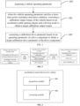
- FIG. 1 is a flow chart for implementing an acceleration control method of a vehicle provided by an embodiment of the present application.
- the method shown in FIG. 1 includes three steps, i.e., step 101 to step 103, which are described in detail below.
- Step 101 acquiring a vehicle operating parameter.
- the purpose of acquiring the vehicle operating parameter is to detect whether the driver has a short-time power assistance intention according to the vehicle operating parameter; when it is detected that the driver has the short-time power assistance intention, it is further determined whether the vehicle operating parameter satisfies the short-time power assistance activation condition. When the vehicle operating parameter satisfies the short-time power assistance activation condition, the operation of step 102 is performed.
- the vehicle operating parameters include at least the parameters, such as a position of a gear lever, a brake pedal opening degree, the accelerator pedal opening degree, a vehicle mode, a torque output, an engine speed, SOC (State of Charge) of a battery, a discharge power of the battery, a battery temperature and an electric-motor temperature during the operation of the vehicle.
- parameters such as a position of a gear lever, a brake pedal opening degree, the accelerator pedal opening degree, a vehicle mode, a torque output, an engine speed, SOC (State of Charge) of a battery, a discharge power of the battery, a battery temperature and an electric-motor temperature during the operation of the vehicle.
- the conditions for the driver to have the short-time power assistance intention include: a current gear lever is in a drive gear, the brake pedal opening degree is zero, an electrical park brake system is not enabled, the accelerator pedal opening degree is greater than a preset pedal opening degree, a rate of change in the accelerator pedal opening degree is greater than a preset rate of change, the vehicle mode is a preset mode, and a difference between a requesting torque and a calibration torque is less than a preset torque value.
- the short-time power assistance activation permit is the first level of protection that ensures the overall vehicle performance during and after the short-time power assistance activation period.
- the present application relates to third levels of vehicle protection for overall vehicle performance, from the first level to the third level, the requirements for short-time power assistance in the vehicle protection at all levels are gradually becoming stricter.
- the conditions for the vehicle operating parameter to satisfy the short-time power assistance activation condition include: the engine is started and the engine speed is within the calibration speed range; and, the operation states of the electric motor, the engine, and the battery are normal; and, the SOC of the battery is greater than the preset SOC; and, a difference between an actual discharge power of the battery and a maximum dynamic discharge power is greater than a preset discharge power value; and, the battery temperature and the electric-motor temperature are within the preset temperature range.
- determining that the engine speed is within a normal range is to provide speed protection for the engine; when the engine speed is high, the short-time power assistance will not be activated to prevent the engine damage due to excessive speed.
- the batteries include a high-voltage battery and a low-voltage battery.
- the high-voltage battery provides power for the vehicle, while the low-voltage battery provides power supply for the instruments of the vehicle; the SOC of the battery is greater than the preset SOC, which means that the SOC of the high-voltage battery is greater than the preset SOC. This is to ensure that during the short-time power assistance activation period, the SOC of the high-voltage battery is within a safe range and can provide sufficient discharge power; and the preset SOC can be calibrated based on a battery capacity and a rated power.
- the difference between the actual discharge power of the battery and the maximum dynamic discharge power is greater than the preset discharge power value, which can ensure that the actual discharge power of the battery will not exceed the maximum dynamic discharge power of the battery due to the short-time power assistance activation; and the preset discharge power value can be calibrated based on the actual discharge power of the battery and the maximum dynamic discharge power of the battery.
- the battery temperature includes a maximum temperature of the battery and a minimum temperature of the battery;
- the electric-motor temperature includes a cooling water temperature, a controller temperature and a stator temperature of the electric motor.
- Step 102 when the vehicle operating parameter satisfies a short-time power assistance activation condition, correcting a calibration output torque of the vehicle based on an accelerator pedal opening degree and a vehicle mode to obtain a target calibration output torque, the target calibration output torque being greater than the calibration output torque.
- the short-time power assistance mode through the step 102 and step 103, the performance of the vehicle is improved and the instantaneous driving capability of the entire vehicle is improved according to the torque path controlled by the vehicle. Because the initial torque request corresponds to the overall vehicle level, the first step is to improve the overall vehicle performance; and then the torque request is allocated to each drive component in the torque path, and the performance of each drive component is improved accordingly.
- the first step is to improve the overall vehicle performance, it should be noted that when improving the overall vehicle performance, the limitation for the driving capability of the entire vehicle is increased. That is, the limitation is released, and the calibrated output torque threshold is increased.
- the focus is not on the operations used to enhance the driving capability of the entire vehicle.
- the existing calibration output torque corresponding to the accelerator pedal opening degree request of the driver is increased on the basis of the original values, thereby increasing the output torque threshold and releasing the torque limitation from the source. Furthermore, even if the vehicle performs existing operations, the overall driving performance can still be improved due to the increase in the output torque threshold.
- step 102 correcting the calibration output torque of the vehicle based on the accelerator pedal opening degree and the vehicle mode to obtain the target calibration output torque, may include step 1 to step 4.
- Step 1 acquiring the accelerator pedal opening degree and a current vehicle mode.
- the vehicle mode may be a sport mode, a sport plus mode, a snow mode, a sand mode, or a mud mode.
- Step 2 determining the calibration output torque corresponding to the accelerator pedal opening degree based on the current vehicle mode.
- the accelerator pedal corresponds to different acceleration curve charts in different vehicle modes.
- the acceleration curve charts can reflect the corresponding relationship between the accelerator pedal opening degree and the output torque.
- the corresponding acceleration curve charts can be determined based on the current vehicle mode first; and then the corresponding output torque is determined from the determined acceleration curve charts based on the accelerator pedal opening degree.
- the output torque is an output torque under a normal operating state of the vehicle, therefore it is referred to as the calibration output torque in the present application.
- Step 3 determining a corresponding output torque corrected value based on the accelerator pedal opening degree.
- the corresponding output torque correction value can be determined by looking up a table based on the accelerator pedal opening degree.
- the table can be an accelerator pedal opening degree-output torque correction value preset table, in the preset table, different accelerator pedal opening degrees correspond to different output torque correction values; the greater the accelerator pedal opening degree, the greater the torque requested by the driver and the greater the willingness to accelerate, therefore, the larger the corresponding output torque correction value that should be set, to meet the acceleration requirements of the driver.
- the output torque correction value when the accelerator pedal opening degree is 60, the output torque correction value may be 0.9; when the accelerator pedal opening degree is 70, the output torque correction value may be 0.95; when the accelerator pedal opening degree is 80, the output torque correction value may be 1; when the accelerator pedal opening degree is 85, the output torque correction value may be 1.1; when the accelerator pedal opening degree is 90, the output torque correction value may be 1.2; and when the accelerator pedal opening degree is 95, the output torque correction value may be 1.25, and so on.
- the above examples are for illustration only, the accelerator pedal opening degree and corresponding output torque correction value can be set according to actual requirements.
- Step 4 calculating a sum of the output torque corrected value and the calibration output torque, to obtain the target calibration output torque.
- the obtained target calibration output torque is higher than the calibration output torque, which increases the output torque threshold corresponding to the accelerator pedal opening degree request of the driver, thereby improving the overall driving capability of the entire vehicle.
- the performance improvement of the entire vehicle After the performance improvement of the entire vehicle is completed, it is necessary to further improve the performance of each component. Otherwise, in subsequent execution, the performance improvement of the entire vehicle will be limited by the requirements of each component, resulting in the inability to achieve short-time acceleration of the entire vehicle.
- the acceleration control method of the vehicle further includes: limiting a power of a high-voltage component to a preset power value.
- a power of a high-voltage component to a preset power value.
- the high-voltage component may include an air conditioner and a DCDC (Direct current-Direct current) converter.
- DCDC Direct current-Direct current
- the step of limiting the power of the high-voltage component to the preset power value includes:
- the limitation of the air conditioner can be executed first, followed by the limitation of the DCDC converter.
- the limitation of the DCDC converter may be executed first, and then the limitation of the air conditioner is executed.
- the various calibration gears of the air conditioner correspond to different output powers of the air conditioner, and different output powers of the air conditioner have different temperature adjustment effects.
- When setting the output powers of the air conditioner to the lowest gear of the calibration gear it can not only ensure that the cabin temperature is appropriate and but also reduce the output power of the air conditioner.
- Step 103 correcting a calibration drive parameter based on an operating parameter of a drive component to obtain a target calibration drive parameter of the drive component, a corresponding value of the target calibration drive parameter being greater than a corresponding value of the calibration drive parameter.
- This step achieves performance improvement of the drive components.
- the drive components have been upgraded to the basic execution part of short-time driving, and also serve as the second level of protection to ensure the overall vehicle performance during and after short-time power assistance activation period. While improving the performance of the drive components, the normal operation of the vehicle after the short-time power assistance exits is considered.
- the drive components may include the battery and the electric motor.
- the discharge power of the battery can provide driving force for the vehicle, while the electric motor can provide drive torque for the vehicle.
- a part of step 103: correcting the calibration drive parameter based on the operating parameter of the drive component to obtain the target calibration drive parameter of the drive component may include the following steps: acquiring a dynamic discharge power of the battery; switching a discharge power of the battery to a calibration dynamic discharge power; acquiring a dynamic discharge power correction factor; and correcting the calibration dynamic discharge power according to the dynamic discharge power correction factor, to obtain a target calibration discharge power.
- the dynamic discharge power of the battery is relatively high, which is several kilowatts higher than the sustainable discharge power of the battery at the room temperature, and can provide high discharge power for a short time for the vehicle. Therefore, after the short-time power assistance mode is activated, the available power of the vehicle can be switched from the sustainable discharge power to the dynamic discharge power.
- the dynamic discharge power correction factor may be acquired by the following steps: acquiring a maximum temperature and a minimum temperature of the battery; calculating an average temperature of the battery according to the maximum temperature and the minimum temperature; and acquiring SOC of the battery, and obtaining the corresponding dynamic discharge power correction factor by looking up a table according to the SOC and the average temperature.
- the battery management system can collect the temperatures of a plurality of temperature sensors disposed at different positions on the battery module, thereby determining the maximum temperature and the minimum temperature from a plurality of temperatures.
- the maximum temperature or the minimum temperature of the battery module used alone cannot reflect the current actual state of the battery. Therefore, the maximum temperature and the minimum temperature can be weighted to obtain the average temperature of the battery.
- HVBT represents the average temperature of the battery
- X represents the weighting factor corresponding to the minimum temperature of the battery at current time (different minimum temperatures correspond to different weighting factors)
- HVBLT represents the minimum temperature of the battery at current time
- HVBHT represents the maximum temperature of the battery at current time.
- the corresponding dynamic discharge power correction factor can be obtained by looking up the preset table based on the SOC and average temperature of the battery.
- the preset table can reflect the corresponding relationship between the SOC, average temperature, and dynamic discharge power correction factor of the battery.
- the maximum duration T1 of the short-time power assistance for the corresponding battery can also be obtained by looking up the preset table mentioned above. That is to say, the above preset table can reflect the corresponding relationship between the SOC, average temperature dynamics, discharge power correction factor, and T1 of the battery.
- the maximum duration of the short-time power assistance here limits the duration of the short-time power assistance for the battery; after exceeding this duration, the output power of the battery will decrease. Therefore, the maximum duration of the short-time power assistance for the battery can be used to determine when to exit the short-time power assistance mode.
- the target calibration discharge power is obtained, so that the target calibration discharge power of the battery can be improved based on the current operating parameters of the battery.
- a part of the step 103: correcting the calibration drive parameter based on the operating parameter of the drive component to obtain the target calibration drive parameter of the drive component may include the following steps A to D.
- Step A acquiring a cooling water temperature, a controller temperature and a stator temperature of the electric motor; when improving the performance of the electric motor, the drive torque is mainly determined based on the temperature of the electric motor.
- Step B determining a corresponding calibration drive torque by looking up a table according to the cooling water temperature; according to this table, the corresponding maximum duration T2 of the short-time power assistance for the electric motor can also be determined. That is to say, this table can reflect the corresponding relationship between cooling water temperature, drive torque, and the maximum duration of the short-time power assistance.
- the maximum duration of the short-time power assistance here limits the duration of the short-time power assistance for the electric motor; after exceeding this duration, the drive torque of the electric motor will decrease. Therefore, the maximum duration of the short-time power assistance for the electric motor can be used to determine when to exit the short-time power assistance mode.
- Step C in a first stage of the short-time power assistance, determining a corresponding first torque correction factor by looking up a table according to the controller temperature, and calculating a sum of the first torque correction factor and the calibration drive torque, to obtain a target calibration drive torque corresponding to the first stage.
- the electric motor In the first stage of the short-time power assistance, the electric motor is in a stage with a low speed and a high torque, and the temperature of the controller of the electric motor rises rapidly, which is the actual temperature that affects the driving capability of the electric motor at this time. Therefore, the first torque correction factor is determined based on the controller temperature.
- Step D in a second stage of the short-time power assistance, determining a corresponding second torque correction factor by looking up a table according to the stator temperature, and calculating a sum of the second torque correction factor and the calibration drive torque, to obtain a target calibration drive torque corresponding to the second stage.
- the entire vehicle In the second stage of the short-time power assistance, the entire vehicle is in a stage with rapid acceleration at a mid-high speed, and the stator temperature of the electric motor rises rapidly, which is the actual temperature that affects the driving capability of the electric motor at this time. Therefore, the second torque correction factor is determined based on the stator temperature.
- the calibrated drive torque may be corrected accurately at different stages of the short-time power assistance, to obtain an accurate target calibration drive torque, and maximize the power performance of the electric motor.
- different torque correction factors are used at different stages of the short-time power assistance, which can ensure that the electric motor will not be damaged due to overheating during the short-time power assistance. At the same time, it can also ensure that the electric motor can be quickly cooled down and return to the normal operating state after the short-time power assistance is completed.
- the acceleration control method of the vehicle further includes the following step: when the vehicle operating parameter satisfies a short-time power assistance exit condition, exiting a short-time power assistance mode.
- the short-time power assistance exit condition may include three conditions, when any one of the conditions is satisfied, the short-time power assistance mode can be exited.
- the first condition is the exit of the drive component
- the second condition is timeout
- the third condition is receiving the exit signal.
- the exit of the drive component includes battery protection exit and electric-motor protection exit, which are the third level of protection that ensures the overall vehicle performance after exiting the short-time power assistance activation.
- the short-time power assistance mode is exited. In order to avoid the battery temperature being too high, which may cause a drop pit in the discharge power of the vehicle when exiting the short-time power assistance mode.
- the short-time power assistance is exited to maintain electricity balance.
- the preset time lasting for here can be obtained by looking up a table based on the difference between the battery discharge power and the maximum dynamic discharge power.
- the short-time power assistance mode is exited to prevent irreversible damage to the electric motor.
- T 1 and T 2 are the longest duration of the short-time power assistance corresponding to the battery and electric motor, respectively. If it is exceeded, it will cause damage to the battery or electric motor. Therefore, the duration of the short-time power assistance is limited to the smaller of the two.
- the exit signal may be an accelerator pedal opening degree signal.
- the preset opening degree here can be 50%, 60%, etc., with a preferred value of 60%.
- a signal rising edge holding module can be set up after entering the short-time power assistance mode, such as an SR trigger. After activating the short-time power assistance mode, the rising edge holding module holds all signals that can be obtained to prevent other signals from affecting the current short-time power assistance mode, until the condition for exiting the short-time power assistance mode is activated, the SR trigger returns to the reset state.
- a timing module is required to determine when to exit the short-time power assistance mode based on the timing time.
- a filtering module can be set up to filter various signals output during the short-time power assistance execution process.
- the driving capability of the entire vehicle can be improved.
- the power of high-voltage component is limited, so that more power can be allocated to the drive components, thus increasing the discharge power and drive torque of the drive components, which can enable the drive component has a higher instantaneous driving capability, and meet the short-time acceleration requirements of the driver, to make the entire vehicle has a better instantaneous acceleration capability, thereby solving the technical problem of poor short-time acceleration capability in existing pure electric or hybrid electric vehicles.
- the above acceleration control method of the vehicle also sets up a three-level vehicle performance protection mechanism to ensure that the vehicle can not only improve its overall performance by activating the short-time power assistance, but also ensure smooth torque transfer and prevent the occurrence of driving drop pits after exiting the short-time power assistance mode.
- FIG. 3 is a schematic diagram of the structural composition of the acceleration control device of the vehicle provided by the present application. For ease of explanation, only the parts related to the present application are shown in this figure, as detailed below.
- the acceleration control device of the vehicle includes: an acquisition module 301 and a correcting module 302.
- the acquisition module 301 is configured for acquiring a vehicle operating parameter.
- the correcting module 302 is configured for, when the vehicle operating parameter satisfies a short-time power assistance activation condition, correcting a calibration output torque of the vehicle based on an accelerator pedal opening degree and a vehicle mode to obtain a target calibration output torque, the target calibration output torque being greater than the calibration output torque.
- the correcting module 302 is further configured for correcting a calibration drive parameter based on an operating parameter of a drive component to obtain a target calibration drive parameter of the drive component, and a corresponding value of the target calibration drive parameter is greater than a corresponding value of the calibration drive parameter.
- the correcting module 302 corrects the calibration output torque of the vehicle based on the accelerator pedal opening degree and the vehicle mode to obtain the target calibration output torque, and the correcting module 302 is configured for:
- the correcting module 302 is further configured for: limiting a power of a high-voltage component to a preset power value.
- the high-voltage component includes an air conditioner and a DCDC (Direct current-Direct current) converter;
- the drive component includes a battery
- the correcting module 302 acquires the dynamic discharge power correction factor, and the correcting module 302 is configured for:
- the drive component includes an electric motor; short-time power assistance of the vehicle is divided into two stages;
- the acceleration control device of the vehicle further includes: a detection module 303 and a triggering module 304.
- the detection module 303 is configured for detecting whether a driver has a short-time power assistance intention according to the vehicle operating parameter.
- the detection module 303 is further configured for, when it is detected that the driver has the short-time power assistance intention, detecting whether the vehicle operating parameter satisfies the short-time power assistance activation condition.
- the triggering module 304 is configured for setting a short-time power assistance activation flag bit, and entering a short-time power assistance mode.
- the triggering module 304 is further configured for exiting a short-time power assistance mode.
- the correcting module can improve the driving capability of the entire vehicle.
- the power of high-voltage component is limited, so that more power can be allocated to the drive components, thus increasing the discharge power and drive torque of the drive components, which can enable the drive component has a higher instantaneous driving capability, and meet the short-time acceleration requirements of the driver, to make the entire vehicle has a better instantaneous acceleration capability, thereby solving the technical problem of poor short-time acceleration capability in existing pure electric or hybrid electric vehicles.
- the above acceleration control device of the vehicle also sets up a three-level vehicle performance protection mechanism to ensure that the vehicle can not only improve its overall performance by activating the short-time power assistance, but also ensure smooth torque transfer and prevent the occurrence of driving drop pits after exiting the short-time power assistance mode.
- the present application also provides a vehicle, and the vehicle includes an electronic device shown in FIG. 5 .
- the electronic device 5 includes: a processor 50, a memory 51, and a computer program 52 stored in the memory 51 and executable on the processor 50.
- the processor 50 when executes the computer program 52, implements the steps of the acceleration control method of the vehicle as described above, such as step 101 to step 103 shown in FIG. 1 .
- the processor 50 executes the computer program 52, it implements the functions of each module/unit in the above device embodiments, such as the functions of modules 301 to 302 shown in FIG. 3 or the functions of modules 301 to 304 shown in FIG. 4 .
- the computer program 52 can be divided into one or more modules/units.
- the computer program 52 can be divided into modules 301 to 302 shown in FIG. 3 or modules 301 to 304 shown in FIG. 4 .
- These modules/units can be stored in the memory 51 and executed by the processor 50 to implement the various embodiments described above in the present application.
- These modules/units can be a series of computer program instruction segments capable of performing specific functions, and which can describe the execution process of the computer program 52 in the electronic device 5.
- the electronic device 5 may include, but is not limited to, a processor 50 and a memory 51. Persons skilled in the art can understand that FIG. 5 is only an example of the electronic device 5 and does not constitute a limitation on the electronic device 5.
- the electronic device 5 may include more or fewer components than components shown in the figure, or a combination of certain components, or different components.
- electronic device 5 may also include input/output devices, network access devices, buses, etc.
- the processor 50 can be a Central Processing Unit (CPU), as well as other general-purpose processors, Digital Signal Processor (DSP), Application Specific Integrated Circuit (ASIC), Field-Programmable Gate Array (FPGA), or other programmable logic devices, discrete gates or transistor logic devices, discrete hardware components, etc.
- DSP Digital Signal Processor
- ASIC Application Specific Integrated Circuit
- FPGA Field-Programmable Gate Array
- the above-mentioned general-purpose processor can be a microprocessor or any other conventional processor, etc.
- the memory 51 can be an internal storage unit of the electronic device 5, such as the hard drive or memory of the electronic device 5.
- the memory 51 can also be an external storage device of the electronic device 5, such as a plug-in hard drive, Smart Media Card (SMC), Secure Digital (SD) card, Flash Card, etc. equipped on the electronic device 5.
- the memory 51 can also include both internal storage units of the electronic device 5 and external storage devices.
- the memory 51 is used to store the computer programs 52 and other programs and data required by the electronic device 5.
- the memory 51 can also be used to temporarily store data that has been or will be output.
- the disclosed devices/electronic devices and methods can be implemented in other ways.
- the embodiments of the device/electronic device described above is only illustrative.
- the division of the modules or units is only a logical functional division, and there may be other ways of division in actual implementation.
- multiple units or components can be combined or integrated into another system, or some features can be ignored or not executed.
- the mutual coupling or direct coupling or communication connection displayed or discussed can be indirect coupling or communication connection through some interfaces, devices or units, which can be electrical, mechanical or other forms.
- the units described as separate components may or may not be physically separated, and the components displayed as units may or may not be physical units. That is, the above components and units can be located in one place or distributed across multiple network units. Some or all of the units can be selected according to actual needs to achieve the goals of various solutions of the embodiments.
- integrated modules/units When integrated modules/units are implemented in the form of software functional units and sold or used as independent products, they can be stored in a computer-readable storage medium. Based on this understanding, the present application implements all or part of the processes in the above-mentioned method embodiments, which can be completed by controlling the relevant hardware through the computer programs.
- the computer program can be stored in a computer-readable storage medium, and when executed by a processor, it can implement the steps of the various acceleration control methods of the vehicle described above.
- the computer programs include computer program codes, which can be in the form of source codes, object codes, executable files, or some intermediate forms.
- the computer-readable medium can include: any entity or device capable of carrying the computer program codes, recording mediums, USB flash drives, portable hard drives, magnetic disks, optical disks, computer memory, read-only memory (ROM), random access memory (RAM), electric carrier signals, telecommunications signals, and software distribution medium.
- ROM read-only memory
- RAM random access memory
- electric carrier signals telecommunications signals
- software distribution medium any entity or device capable of carrying the computer program codes, recording mediums, USB flash drives, portable hard drives, magnetic disks, optical disks, computer memory, read-only memory (ROM), random access memory (RAM), electric carrier signals, telecommunications signals, and software distribution medium.
- the content contained in the computer-readable medium can be appropriately added or removed according to the requirements of legislation and patent practice within the jurisdiction.
- the computer-readable medium do not include the electric carrier signals and the telecommunications signals.
Landscapes
- Engineering & Computer Science (AREA)
- Chemical & Material Sciences (AREA)
- Combustion & Propulsion (AREA)
- Transportation (AREA)
- Mechanical Engineering (AREA)
- Automation & Control Theory (AREA)
- Electric Propulsion And Braking For Vehicles (AREA)
Abstract
Description
- The application claims the priority of the Chinese patent application filed on
December 28th, 2021 with the application number of CN202111626861.7 - The present application relates to the technical field of vehicle power system, and particularly to an acceleration control method and device of a vehicle, a vehicle, and a storage medium.
- In modern society, the large number of internal combustion locomotives has led to increasingly serious environmental pollution problems, and the fossil fuels they consume are non-renewable. This has made the application of hybrid vehicles increasingly widespread. The commonly referred hybrid vehicles generally refer to hybrid electric vehicles, which use electric motors and traditional internal combustion engines as power sources.
- Most hybrid vehicles use batteries as their onboard energy storage carrier. However, the existing batteries have a lower specific power, which limits the acceleration performance of the vehicle. The specific power can characterize the ability of a battery to release or absorb energy per unit time. The higher the specific power, the more energy the battery can release per unit time, and the better the acceleration performance of the vehicle. On the contrary, if the specific power is low, the energy that the battery can release per unit time is limited. Which cannot meet the instantaneous high-power requirement of the vehicle, resulting in poor acceleration performance of the vehicle. To solve this problem, the current common method is to increase the number of the batteries. However, this method will increase the cost and weight of the vehicle.
- The present application provides an acceleration control method and device of a vehicle, a vehicle, and a storage medium, to solve a technical problem of poor short-time acceleration capability in existing pure electric or hybrid electric vehicles.
- In a first aspect, the present application provides an acceleration control method of a vehicle, and the method includes:
- acquiring a vehicle operating parameter;
- when the vehicle operating parameter satisfies a short-time power assistance activation condition, correcting a calibration output torque of the vehicle based on an accelerator pedal opening degree and a vehicle mode to obtain a target calibration output torque, the target calibration output torque being greater than the calibration output torque; and
- correcting a calibration drive parameter based on an operating parameter of a drive component to obtain a target calibration drive parameter of the drive component, a corresponding value of the target calibration drive parameter being greater than a corresponding value of the calibration drive parameter.
- In a possible embodiment, correcting the calibration output torque of the vehicle based on the accelerator pedal opening degree and the vehicle mode to obtain the target calibration output torque includes:
- acquiring the accelerator pedal opening degree and a current vehicle mode;
- determining the calibration output torque corresponding to the accelerator pedal opening degree based on the current vehicle mode;
- determining a corresponding output torque corrected value based on the accelerator pedal opening degree; and
- calculating a sum of the output torque corrected value and the calibration output torque, to obtain the target calibration output torque.
- In a possible embodiment, after correcting the calibration output torque of the vehicle based on the accelerator pedal opening degree and the vehicle mode to obtain the target calibration output torque, and before correcting the calibration drive parameter based on the operating parameter of the drive component to obtain the target calibration drive parameter of the drive component, the acceleration control method of the vehicle further includes: limiting a power of a high-voltage component to a preset power value.
- In a possible embodiment, the high-voltage component includes an air conditioner and a DCDC (Direct current-Direct current) converter;
- limiting the power of the high-voltage component to the preset power value includes:
- setting an output power of the air conditioner to a lowest gear of a calibration gear;
- calculating a calibrated charging power based on SOC (State of Charge) of a low-voltage battery on a low-voltage side of the DCDC converter, the calibrated charging power being a charging power calculated based on a minimum voltage electricity consumption of the low-voltage battery; and setting a charging power of the low-voltage battery to the calibrated charging power.
- In a possible embodiment, the drive component includes a battery;
- correcting the calibration drive parameter based on the operating parameter of the drive component to obtain the target calibration drive parameter of the drive component includes:
- acquiring a dynamic discharge power of the battery;
- switching a discharge power of the battery to a calibration dynamic discharge power;
- acquiring a dynamic discharge power correction factor;
- correcting the calibration dynamic discharge power according to the dynamic discharge power correction factor, to obtain a target calibration discharge power.
- In a possible embodiment, acquiring the dynamic discharge power correction factor includes:
- acquiring a maximum temperature and a minimum temperature of the battery;
- calculating an average temperature of the battery according to the maximum temperature and the minimum temperature; and
- acquiring SOC of the battery, and obtaining the corresponding dynamic discharge power correction factor by looking up a table according to the SOC and the average temperature.
- In a possible embodiment, the average temperature of the battery is calculated by following steps:
- obtaining a weighting factor corresponding to the minimum temperature by looking up a table according to the minimum temperature of the battery;
- calculating the average temperature of the battery according to HVBT=X*HVBLT+(1-X)*HVBHT; where HVBT represents the average temperature of the battery, HVBLT represents the minimum temperature of the battery, HVBHT represents the maximum temperature of the battery at current time, and X represents the weighting factor.
- In a possible embodiment, the drive component includes an electric motor; short-time power assistance of the vehicle is divided into two stages;
- correcting the calibration drive parameter based on the operating parameter of the drive component to obtain the target calibration drive parameter of the drive component includes:
- acquiring a cooling water temperature, a controller temperature and a stator temperature of the electric motor;
- determining a corresponding calibration drive torque by looking up a table according to the cooling water temperature;
- in a first stage of the short-time power assistance, determining a corresponding first torque correction factor by looking up a table according to the controller temperature, and calculating a sum of the first torque correction factor and the calibration drive torque, to obtain a target calibration drive torque corresponding to the first stage; and
- in a second stage of the short-time power assistance, determining a corresponding second torque correction factor by looking up a table according to the stator temperature, and calculating a sum of the second torque correction factor and the calibration drive torque, to obtain a target calibration drive torque corresponding to the second stage.
- In a possible embodiment, determination of the vehicle operating parameter includes:
- detecting whether a driver has a short-time power assistance intention according to the vehicle operating parameter; and
- when it is detected that the driver has the short-time power assistance intention, detecting whether the vehicle operating parameter satisfies the short-time power assistance activation condition;
- after the vehicle operating parameter satisfies the short-time power assistance activation condition, the acceleration control method of the vehicle further includes:
- setting a short-time power assistance activation flag bit, and entering a short-time power assistance mode.
- In a possible embodiment, the vehicle operating parameter includes one or more of following parameters: a position of a gear lever, a brake pedal opening degree, the accelerator pedal opening degree, a vehicle mode, a torque output, an engine speed, SOC of a battery, a discharge power of the battery, a battery temperature and an electric-motor temperature.
- In a possible embodiment, it is determined that the driver has the short-time power assistance intention when one or more of following conditions are satisfied a gear lever is in a drive gear, a brake pedal opening degree is zero, an electrical park brake system is not enabled, the accelerator pedal opening degree is greater than a preset pedal opening degree, a rate of change in the accelerator pedal opening degree is greater than a preset rate of change, a vehicle mode is a preset mode, and a difference between a requesting torque and a calibration torque is less than a preset torque value.
- In a possible embodiment, after correcting the calibration drive parameter based on the operating parameter of the drive component to obtain the target calibration drive parameter of the drive component, the acceleration control method of the vehicle further includes:
when the vehicle operating parameter satisfies a short-time power assistance exit condition, exiting a short-time power assistance mode. - In a second aspect, the present application provides an acceleration control device of a vehicle, and the device includes:
- an acquisition module configured for acquiring a vehicle operating parameter;
- a first correcting module configured for, when the vehicle operating parameter satisfies a short-time power assistance activation condition, correcting a calibration output torque of the vehicle based on an accelerator pedal opening degree and a vehicle mode to obtain a target calibration output torque, the target calibration output torque being greater than the calibration output torque; and
- a second correcting module further configured for correcting a calibration drive parameter based on an operating parameter of a drive component to obtain a target calibration drive parameter of the drive component, a corresponding value of the target calibration drive parameter being greater than a corresponding value of the calibration drive parameter.
- In a third aspect, the present application provides a vehicle, including an electronic device, the electronic device including a memory, a processor, and a computer program stored in the memory and executable on the processor, and the processor, when executes the computer program, implements the steps of the acceleration control method of the vehicle according to the first aspect or any possible embodiment of the first aspect.
- In a fourth aspect, the present application provides a computer-readable storage medium, storing a computer program, and the processor, when executes the computer program, implements the steps of the acceleration control method of the vehicle according to the first aspect or any possible embodiment of the first aspect.
- The embodiments of the present application have the following advantages:
- In the acceleration control method of the vehicle provided by the present application, it may be determined whether the vehicle satisfies the short-time power assistance activation condition according to the vehicle operating parameter, and after entering the short-time power assistance mode, the driving capability of the entire vehicle can be improved. That is, the upper limit of the calibration output torque of the entire vehicle is improved, the discharge power and drive torque of the drive component is improved, and the upper limit of the calibration drive parameter of the drive component is improved, so that the torque request of the driver is responded to within the corresponding controllable output torque range, and will not be unable to obtain the response of the corresponding output torque due to the torque request being too large. The acceleration control method of the vehicle provided by the present application can improve the instantaneous driving capability of the drive component, enabling the entire vehicle to have better instantaneous acceleration capability and meet the short-time acceleration requirements of the driver, thereby solving the technical problem of poor short-time acceleration capability in existing pure electric or hybrid electric vehicles.
- In order to more clearly illustrate the technical solutions of the embodiments of the present application, the figures that are required to describe the embodiments or the prior art will be briefly described below. Apparently, the figures that are described below are merely some embodiments of the present application, and a person skilled in the art can obtain other figures according to these figures without paying creative work.
-
FIG. 1 is a flow chart for implementing an acceleration control method of a vehicle according to an embodiment of the present application; -
FIG. 2 is another flow chart for implementing an acceleration control method of a vehicle according to an embodiment of the present application; -
FIG. 3 is a schematic diagram of structural composition of an acceleration control device of a vehicle according to an embodiment of the present application; -
FIG. 4 is another schematic diagram of structural composition of an acceleration control device of a vehicle according to an embodiment of the present application; and -
FIG. 5 is a schematic diagram of structural composition of an electronic device according to an embodiment of the present application. - In the following description, specific details such as specific system structures and technologies are provided for illustrating purposes rather than limitation, to facilitate a thorough understanding of the embodiments of the present application. However, persons skilled in the art should be understood that the present application can also be implemented in other embodiments without these specific details. In other cases, detailed descriptions of well-known systems, devices, circuits, and methods are omitted to avoid unnecessary details hindering the description of the present application.
- In order to clarify the purpose, technical solution, and advantages of the present application, specific embodiments will be described below in conjunction with the accompanying drawings.
-
FIG. 1 is a flow chart for implementing an acceleration control method of a vehicle provided by an embodiment of the present application. The method shown inFIG. 1 includes three steps, i.e., step 101 to step 103, which are described in detail below. -
Step 101, acquiring a vehicle operating parameter. - The purpose of acquiring the vehicle operating parameter is to detect whether the driver has a short-time power assistance intention according to the vehicle operating parameter; when it is detected that the driver has the short-time power assistance intention, it is further determined whether the vehicle operating parameter satisfies the short-time power assistance activation condition. When the vehicle operating parameter satisfies the short-time power assistance activation condition, the operation of
step 102 is performed. - The vehicle operating parameters include at least the parameters, such as a position of a gear lever, a brake pedal opening degree, the accelerator pedal opening degree, a vehicle mode, a torque output, an engine speed, SOC (State of Charge) of a battery, a discharge power of the battery, a battery temperature and an electric-motor temperature during the operation of the vehicle.
- The conditions for the driver to have the short-time power assistance intention include: a current gear lever is in a drive gear, the brake pedal opening degree is zero, an electrical park brake system is not enabled, the accelerator pedal opening degree is greater than a preset pedal opening degree, a rate of change in the accelerator pedal opening degree is greater than a preset rate of change, the vehicle mode is a preset mode, and a difference between a requesting torque and a calibration torque is less than a preset torque value.
- Among them:
- the drive gears include D gear (drive), R gear (reverse), or M gear (manual);
- the brake pedal opening degree is zero, which means the driver did not step on the brake pedal and did not brake;
- the preset pedal opening can be set to 70%, 80%, 85%, etc., with a preferred value of 80%;
- the preset rate of change in the accelerator pedal opening degree can be set to 35%, 40%, 50%, etc., with a preferred value of 40%;
- the preset mode can be a sport mode, a sport plus mode, and some modes adapted to the terrain, such as a snow mode, a sand mode, or a mud mode;
- the calibration torque is a torque corresponding to a steady-state driving of the entire vehicle; when the difference between the requesting torque and the calibration torque is less than the preset torque value, the increase in the requesting torque compared to the calibration torque is relatively small, which allows the torque to smoothly change before and after short-time power assistance activation without creating a drop pit.
- When the vehicle operating parameter does not satisfy any one of the above conditions, it is determined that the driver has no short-time power assistance intention and the process ends.
- The short-time power assistance activation permit is the first level of protection that ensures the overall vehicle performance during and after the short-time power assistance activation period. The present application relates to third levels of vehicle protection for overall vehicle performance, from the first level to the third level, the requirements for short-time power assistance in the vehicle protection at all levels are gradually becoming stricter.
- The conditions for the vehicle operating parameter to satisfy the short-time power assistance activation condition include: the engine is started and the engine speed is within the calibration speed range; and, the operation states of the electric motor, the engine, and the battery are normal; and, the SOC of the battery is greater than the preset SOC; and, a difference between an actual discharge power of the battery and a maximum dynamic discharge power is greater than a preset discharge power value; and, the battery temperature and the electric-motor temperature are within the preset temperature range.
- Among them:
determining that the engine speed is within a normal range is to provide speed protection for the engine; when the engine speed is high, the short-time power assistance will not be activated to prevent the engine damage due to excessive speed. - The batteries include a high-voltage battery and a low-voltage battery. The high-voltage battery provides power for the vehicle, while the low-voltage battery provides power supply for the instruments of the vehicle; the SOC of the battery is greater than the preset SOC, which means that the SOC of the high-voltage battery is greater than the preset SOC. This is to ensure that during the short-time power assistance activation period, the SOC of the high-voltage battery is within a safe range and can provide sufficient discharge power; and the preset SOC can be calibrated based on a battery capacity and a rated power.
- The difference between the actual discharge power of the battery and the maximum dynamic discharge power is greater than the preset discharge power value, which can ensure that the actual discharge power of the battery will not exceed the maximum dynamic discharge power of the battery due to the short-time power assistance activation; and the preset discharge power value can be calibrated based on the actual discharge power of the battery and the maximum dynamic discharge power of the battery.
- The battery temperature includes a maximum temperature of the battery and a minimum temperature of the battery; the electric-motor temperature includes a cooling water temperature, a controller temperature and a stator temperature of the electric motor.
- When any one of the short-time power assistance activation conditions mentioned above is not satisfied, the process ends.
-
Step 102, when the vehicle operating parameter satisfies a short-time power assistance activation condition, correcting a calibration output torque of the vehicle based on an accelerator pedal opening degree and a vehicle mode to obtain a target calibration output torque, the target calibration output torque being greater than the calibration output torque. - When all the vehicle operating parameters satisfy the short-time power assistance activation condition, setting a short-time power assistance activation flag bit, and entering a short-time power assistance mode. In the short-time power assistance mode, through the
step 102 and step 103, the performance of the vehicle is improved and the instantaneous driving capability of the entire vehicle is improved according to the torque path controlled by the vehicle. Because the initial torque request corresponds to the overall vehicle level, the first step is to improve the overall vehicle performance; and then the torque request is allocated to each drive component in the torque path, and the performance of each drive component is improved accordingly. - The first step is to improve the overall vehicle performance, it should be noted that when improving the overall vehicle performance, the limitation for the driving capability of the entire vehicle is increased. That is, the limitation is released, and the calibrated output torque threshold is increased. When improving the overall vehicle performance here, the focus is not on the operations used to enhance the driving capability of the entire vehicle. In the
step 102, the existing calibration output torque corresponding to the accelerator pedal opening degree request of the driver is increased on the basis of the original values, thereby increasing the output torque threshold and releasing the torque limitation from the source. Furthermore, even if the vehicle performs existing operations, the overall driving performance can still be improved due to the increase in the output torque threshold. - The following step in the step 102: correcting the calibration output torque of the vehicle based on the accelerator pedal opening degree and the vehicle mode to obtain the target calibration output torque, may include step 1 to step 4.
- Step 1, acquiring the accelerator pedal opening degree and a current vehicle mode.
- The vehicle mode may be a sport mode, a sport plus mode, a snow mode, a sand mode, or a mud mode.
- Step 2, determining the calibration output torque corresponding to the accelerator pedal opening degree based on the current vehicle mode.
- The accelerator pedal corresponds to different acceleration curve charts in different vehicle modes. The acceleration curve charts can reflect the corresponding relationship between the accelerator pedal opening degree and the output torque. In the step 1 and the step 2, the corresponding acceleration curve charts can be determined based on the current vehicle mode first; and then the corresponding output torque is determined from the determined acceleration curve charts based on the accelerator pedal opening degree. The output torque is an output torque under a normal operating state of the vehicle, therefore it is referred to as the calibration output torque in the present application.
- Step 3, determining a corresponding output torque corrected value based on the accelerator pedal opening degree.
- In this step, the corresponding output torque correction value can be determined by looking up a table based on the accelerator pedal opening degree. The table can be an accelerator pedal opening degree-output torque correction value preset table, in the preset table, different accelerator pedal opening degrees correspond to different output torque correction values; the greater the accelerator pedal opening degree, the greater the torque requested by the driver and the greater the willingness to accelerate, therefore, the larger the corresponding output torque correction value that should be set, to meet the acceleration requirements of the driver.
- For example, when the accelerator pedal opening degree is 60, the output torque correction value may be 0.9; when the accelerator pedal opening degree is 70, the output torque correction value may be 0.95; when the accelerator pedal opening degree is 80, the output torque correction value may be 1; when the accelerator pedal opening degree is 85, the output torque correction value may be 1.1; when the accelerator pedal opening degree is 90, the output torque correction value may be 1.2; and when the accelerator pedal opening degree is 95, the output torque correction value may be 1.25, and so on. The above examples are for illustration only, the accelerator pedal opening degree and corresponding output torque correction value can be set according to actual requirements.
- Step 4, calculating a sum of the output torque corrected value and the calibration output torque, to obtain the target calibration output torque.
- The obtained target calibration output torque is higher than the calibration output torque, which increases the output torque threshold corresponding to the accelerator pedal opening degree request of the driver, thereby improving the overall driving capability of the entire vehicle.
- After the performance improvement of the entire vehicle is completed, it is necessary to further improve the performance of each component. Otherwise, in subsequent execution, the performance improvement of the entire vehicle will be limited by the requirements of each component, resulting in the inability to achieve short-time acceleration of the entire vehicle.
- After the overall vehicle performance is improved, the torque request is allocated to the drive components in the torque path, and a high-voltage component can be limited at this time. That is, after
step 102 and beforestep 103, the acceleration control method of the vehicle further includes: limiting a power of a high-voltage component to a preset power value. In order to allocate more power to the drive components, we need to impose power limitation on other power consuming components (such as the high-voltage component mentioned above) as long as to ensure their basic power requirements. Then, the performance improvement of the drive components can be performed. - The high-voltage component may include an air conditioner and a DCDC (Direct current-Direct current) converter.
- The step of limiting the power of the high-voltage component to the preset power value includes:
- setting an output power of the air conditioner to a lowest gear of a calibration gear;
- calculating a calibrated charging power based on SOC of a low-voltage battery on a low-voltage side of the DCDC converter, the calibrated charging power being a charging power calculated based on a minimum voltage electricity consumption of the low-voltage battery; and setting a charging power of the low-voltage battery to the calibrated charging power.
- It should be noted that there is no sequence for limiting operations of the air conditioner and the DCDC converter. The limitation of the air conditioner can be executed first, followed by the limitation of the DCDC converter. Alternatively, the limitation of the DCDC converter may be executed first, and then the limitation of the air conditioner is executed.
- The various calibration gears of the air conditioner correspond to different output powers of the air conditioner, and different output powers of the air conditioner have different temperature adjustment effects. When setting the output powers of the air conditioner to the lowest gear of the calibration gear, it can not only ensure that the cabin temperature is appropriate and but also reduce the output power of the air conditioner.
-
Step 103, correcting a calibration drive parameter based on an operating parameter of a drive component to obtain a target calibration drive parameter of the drive component, a corresponding value of the target calibration drive parameter being greater than a corresponding value of the calibration drive parameter. - This step achieves performance improvement of the drive components. The drive components have been upgraded to the basic execution part of short-time driving, and also serve as the second level of protection to ensure the overall vehicle performance during and after short-time power assistance activation period. While improving the performance of the drive components, the normal operation of the vehicle after the short-time power assistance exits is considered.
- The drive components may include the battery and the electric motor. The discharge power of the battery can provide driving force for the vehicle, while the electric motor can provide drive torque for the vehicle.
- When the drive component is the battery, a part of step 103: correcting the calibration drive parameter based on the operating parameter of the drive component to obtain the target calibration drive parameter of the drive component, may include the following steps: acquiring a dynamic discharge power of the battery; switching a discharge power of the battery to a calibration dynamic discharge power; acquiring a dynamic discharge power correction factor; and correcting the calibration dynamic discharge power according to the dynamic discharge power correction factor, to obtain a target calibration discharge power.
- The dynamic discharge power of the battery is relatively high, which is several kilowatts higher than the sustainable discharge power of the battery at the room temperature, and can provide high discharge power for a short time for the vehicle. Therefore, after the short-time power assistance mode is activated, the available power of the vehicle can be switched from the sustainable discharge power to the dynamic discharge power.
- The dynamic discharge power correction factor may be acquired by the following steps: acquiring a maximum temperature and a minimum temperature of the battery; calculating an average temperature of the battery according to the maximum temperature and the minimum temperature; and acquiring SOC of the battery, and obtaining the corresponding dynamic discharge power correction factor by looking up a table according to the SOC and the average temperature.
- When collecting the battery temperature, the battery management system can collect the temperatures of a plurality of temperature sensors disposed at different positions on the battery module, thereby determining the maximum temperature and the minimum temperature from a plurality of temperatures. The maximum temperature or the minimum temperature of the battery module used alone cannot reflect the current actual state of the battery. Therefore, the maximum temperature and the minimum temperature can be weighted to obtain the average temperature of the battery.
- A corresponding weighting factor is obtained by looking up a table according to the minimum temperature of the battery, and then the average temperature of the battery is calculated according to HVBT=X*HVBLT+(1-X)*HVBHT. Where HVBT represents the average temperature of the battery, X represents the weighting factor corresponding to the minimum temperature of the battery at current time (different minimum temperatures correspond to different weighting factors), HVBLT represents the minimum temperature of the battery at current time, and HVBHT represents the maximum temperature of the battery at current time.
- After obtaining the average temperature of the battery, the corresponding dynamic discharge power correction factor can be obtained by looking up the preset table based on the SOC and average temperature of the battery. The preset table can reflect the corresponding relationship between the SOC, average temperature, and dynamic discharge power correction factor of the battery.
- It should be noted that, the maximum duration T1 of the short-time power assistance for the corresponding battery can also be obtained by looking up the preset table mentioned above. That is to say, the above preset table can reflect the corresponding relationship between the SOC, average temperature dynamics, discharge power correction factor, and T1 of the battery. The maximum duration of the short-time power assistance here limits the duration of the short-time power assistance for the battery; after exceeding this duration, the output power of the battery will decrease. Therefore, the maximum duration of the short-time power assistance for the battery can be used to determine when to exit the short-time power assistance mode.
- Finally, based on the sum of the dynamic discharge power correction factor and the calibration dynamic discharge power, the target calibration discharge power is obtained, so that the target calibration discharge power of the battery can be improved based on the current operating parameters of the battery.
- When the drive component is the electric motor, a part of the step 103: correcting the calibration drive parameter based on the operating parameter of the drive component to obtain the target calibration drive parameter of the drive component, may include the following steps A to D.
- Step A, acquiring a cooling water temperature, a controller temperature and a stator temperature of the electric motor; when improving the performance of the electric motor, the drive torque is mainly determined based on the temperature of the electric motor.
- Step B, determining a corresponding calibration drive torque by looking up a table according to the cooling water temperature; according to this table, the corresponding maximum duration T2 of the short-time power assistance for the electric motor can also be determined. That is to say, this table can reflect the corresponding relationship between cooling water temperature, drive torque, and the maximum duration of the short-time power assistance. The maximum duration of the short-time power assistance here limits the duration of the short-time power assistance for the electric motor; after exceeding this duration, the drive torque of the electric motor will decrease. Therefore, the maximum duration of the short-time power assistance for the electric motor can be used to determine when to exit the short-time power assistance mode.
- When the drive component is the electric motor, the short-time power assistance of the vehicle is divided into two stages. Step C, in a first stage of the short-time power assistance, determining a corresponding first torque correction factor by looking up a table according to the controller temperature, and calculating a sum of the first torque correction factor and the calibration drive torque, to obtain a target calibration drive torque corresponding to the first stage.
- In the first stage of the short-time power assistance, the electric motor is in a stage with a low speed and a high torque, and the temperature of the controller of the electric motor rises rapidly, which is the actual temperature that affects the driving capability of the electric motor at this time. Therefore, the first torque correction factor is determined based on the controller temperature.
- Step D, in a second stage of the short-time power assistance, determining a corresponding second torque correction factor by looking up a table according to the stator temperature, and calculating a sum of the second torque correction factor and the calibration drive torque, to obtain a target calibration drive torque corresponding to the second stage.
- In the second stage of the short-time power assistance, the entire vehicle is in a stage with rapid acceleration at a mid-high speed, and the stator temperature of the electric motor rises rapidly, which is the actual temperature that affects the driving capability of the electric motor at this time. Therefore, the second torque correction factor is determined based on the stator temperature.
- By using different torque correction factors at different stages of the short-time power assistance, the calibrated drive torque may be corrected accurately at different stages of the short-time power assistance, to obtain an accurate target calibration drive torque, and maximize the power performance of the electric motor. Moreover, different torque correction factors are used at different stages of the short-time power assistance, which can ensure that the electric motor will not be damaged due to overheating during the short-time power assistance. At the same time, it can also ensure that the electric motor can be quickly cooled down and return to the normal operating state after the short-time power assistance is completed.
- After the
step 103, the acceleration control method of the vehicle further includes the following step: when the vehicle operating parameter satisfies a short-time power assistance exit condition, exiting a short-time power assistance mode. - The short-time power assistance exit condition may include three conditions, when any one of the conditions is satisfied, the short-time power assistance mode can be exited. The first condition is the exit of the drive component, the second condition is timeout, and the third condition is receiving the exit signal.
- Among them, the exit of the drive component includes battery protection exit and electric-motor protection exit, which are the third level of protection that ensures the overall vehicle performance after exiting the short-time power assistance activation.
- When the difference between the maximum temperature of the battery and the maximum temperature at which the battery can continue to operate is less than the preset temperature value, the short-time power assistance mode is exited. In order to avoid the battery temperature being too high, which may cause a drop pit in the discharge power of the vehicle when exiting the short-time power assistance mode.
- When the SOC of the battery is lower than the SOC corresponding to electricity balance of the battery, the short-time power assistance is exited to maintain electricity balance.
- When the difference between the battery discharge power and the maximum dynamic discharge power is less than the preset discharge power value and lasts for a preset time, in order to prevent excessive battery discharge and battery damage, it is necessary to forcibly exit short-time power assistance. The preset time lasting for here can be obtained by looking up a table based on the difference between the battery discharge power and the maximum dynamic discharge power.
- When any one of the cooling water temperature, controller temperature, or stator temperature of the electric motor is greater than or equal to the preset temperature value, the short-time power assistance mode is exited to prevent irreversible damage to the electric motor.
- The condition for timeout exit is that the duration of the short-time power assistance is greater than or equal to the smaller of T1 and T2. T1 and T2 are the longest duration of the short-time power assistance corresponding to the battery and electric motor, respectively. If it is exceeded, it will cause damage to the battery or electric motor. Therefore, the duration of the short-time power assistance is limited to the smaller of the two.
- For the third exit condition mentioned above, which is receiving the exit signal, and the exit signal is provided by the driver. That is to say, the third exit condition mentioned above is actually for the driver to voluntarily exit. The exit signal may be an accelerator pedal opening degree signal. When the accelerator pedal opening degree is less than the preset opening degree, the short-time power assistance mode is exited. The preset opening degree here can be 50%, 60%, etc., with a preferred value of 60%.
- It should be noted that when exiting the short-time power assistance mode, the discharge power of the battery and the output torque gradient of the electric motor decrease, rather than immediately decreasing to the original normal operating level, in order to ensure smooth torque transfer and prevent the occurrence of driving drop pits.
- Referring to
FIG. 2 , in addition to the processes, such as entering the short-time power assistance mode, executing the short-time power assistance, and exiting the short-time power assistance mode involved in the acceleration control method of the vehicle described in the above embodiments, a signal rising edge holding module can be set up after entering the short-time power assistance mode, such as an SR trigger. After activating the short-time power assistance mode, the rising edge holding module holds all signals that can be obtained to prevent other signals from affecting the current short-time power assistance mode, until the condition for exiting the short-time power assistance mode is activated, the SR trigger returns to the reset state. - During the execution of the short-time power assistance, due to the limitations of the battery and electric motor on the duration of the short-time power assistance, the participation of a timing module is required to determine when to exit the short-time power assistance mode based on the timing time. In addition, a filtering module can be set up to filter various signals output during the short-time power assistance execution process.
- In the acceleration control method of the vehicle, after entering the short-time power assistance mode, the driving capability of the entire vehicle can be improved. The power of high-voltage component is limited, so that more power can be allocated to the drive components, thus increasing the discharge power and drive torque of the drive components, which can enable the drive component has a higher instantaneous driving capability, and meet the short-time acceleration requirements of the driver, to make the entire vehicle has a better instantaneous acceleration capability, thereby solving the technical problem of poor short-time acceleration capability in existing pure electric or hybrid electric vehicles. The above acceleration control method of the vehicle also sets up a three-level vehicle performance protection mechanism to ensure that the vehicle can not only improve its overall performance by activating the short-time power assistance, but also ensure smooth torque transfer and prevent the occurrence of driving drop pits after exiting the short-time power assistance mode.
- It should be understood that the size of the sequence number of each step in the above embodiments does not imply the order of execution, and the order of execution of each process should be determined by its function and internal logic; the sequence number of each step should not constitute any limitation on the implementation process of the present application.
- The following is the embodiments of the device in the present application. For details not described in detail, please refer to the corresponding method embodiments mentioned above.
-
FIG. 3 is a schematic diagram of the structural composition of the acceleration control device of the vehicle provided by the present application. For ease of explanation, only the parts related to the present application are shown in this figure, as detailed below. - As shown in
FIG. 3 , the acceleration control device of the vehicle includes: anacquisition module 301 and a correctingmodule 302. - The
acquisition module 301 is configured for acquiring a vehicle operating parameter. - The correcting
module 302 is configured for, when the vehicle operating parameter satisfies a short-time power assistance activation condition, correcting a calibration output torque of the vehicle based on an accelerator pedal opening degree and a vehicle mode to obtain a target calibration output torque, the target calibration output torque being greater than the calibration output torque. - The correcting
module 302 is further configured for correcting a calibration drive parameter based on an operating parameter of a drive component to obtain a target calibration drive parameter of the drive component, and a corresponding value of the target calibration drive parameter is greater than a corresponding value of the calibration drive parameter. - In a possible embodiment, the correcting
module 302 corrects the calibration output torque of the vehicle based on the accelerator pedal opening degree and the vehicle mode to obtain the target calibration output torque, and the correctingmodule 302 is configured for: - acquiring the accelerator pedal opening degree and a current vehicle mode;
- determining the calibration output torque corresponding to the accelerator pedal opening degree based on the current vehicle mode;
- determining a corresponding output torque corrected value based on the accelerator pedal opening degree; and
- calculating a sum of the output torque corrected value and the calibration output torque, to obtain the target calibration output torque.
- In a possible embodiment, after the correcting
module 302 corrects the calibration output torque of the vehicle based on the accelerator pedal opening degree and the vehicle mode to obtain the target calibration output torque, and before the correctingmodule 302 corrects the calibration drive parameter based on the operating parameter of the drive component to obtain the target calibration drive parameter of the drive component, the correctingmodule 302 is further configured for: limiting a power of a high-voltage component to a preset power value. - Among them, the high-voltage component includes an air conditioner and a DCDC (Direct current-Direct current) converter;
- the correcting
module 302 limits the power of the high-voltage component to the preset power value, and the correctingmodule 302 is configured for: - setting an output power of the air conditioner to a lowest gear of a calibration gear;
- calculating a calibrated charging power based on SOC (State of Charge) of a low-voltage battery on a low-voltage side of the DCDC converter, the calibrated charging power being a charging power calculated based on a minimum voltage electricity consumption of the low-voltage battery; and setting a charging power of the low-voltage battery to the calibrated charging power.
- In a possible embodiment, the drive component includes a battery;
- the correcting
module 302 corrects the calibration drive parameter based on the operating parameter of the drive component to obtain the target calibration drive parameter of the drive component, and the correctingmodule 302 is configured for: - acquiring a dynamic discharge power of the battery;
- switching a discharge power of the battery to a calibration dynamic discharge power;
- acquiring a dynamic discharge power correction factor; and
- correcting the calibration dynamic discharge power according to the dynamic discharge power correction factor, to obtain a target calibration discharge power.
- In a possible embodiment, the correcting
module 302 acquires the dynamic discharge power correction factor, and the correctingmodule 302 is configured for: - acquiring a maximum temperature and a minimum temperature of the battery;
- calculating an average temperature of the battery according to the maximum temperature and the minimum temperature; and
- acquiring SOC of the battery, and obtaining the corresponding dynamic discharge power correction factor by looking up a table according to the SOC and the average temperature.
- In a possible embodiment, the drive component includes an electric motor; short-time power assistance of the vehicle is divided into two stages;
- the correcting
module 302 corrects the calibration drive parameter based on the operating parameter of the drive component to obtain the target calibration drive parameter of the drive component, and the correctingmodule 302 is configured for: - acquiring a cooling water temperature, a controller temperature and a stator temperature of the electric motor;
- determining a corresponding calibration drive torque by looking up a table according to the cooling water temperature;
- in a first stage of the short-time power assistance, determining a corresponding first torque correction factor by looking up a table according to the controller temperature, and calculating a sum of the first torque correction factor and the calibration drive torque, to obtain a target calibration drive torque corresponding to the first stage; and
- in a second stage of the short-time power assistance, determining a corresponding second torque correction factor by looking up a table according to the stator temperature, and calculating a sum of the second torque correction factor and the calibration drive torque, to obtain a target calibration drive torque corresponding to the second stage.
- In a possible embodiment, as shown in
FIG. 4 , the acceleration control device of the vehicle further includes: adetection module 303 and a triggeringmodule 304. - After the
acquisition module 301 acquires the vehicle operating parameter, thedetection module 303 is configured for detecting whether a driver has a short-time power assistance intention according to the vehicle operating parameter. - The
detection module 303 is further configured for, when it is detected that the driver has the short-time power assistance intention, detecting whether the vehicle operating parameter satisfies the short-time power assistance activation condition. - The triggering
module 304 is configured for setting a short-time power assistance activation flag bit, and entering a short-time power assistance mode. - After the correcting
module 302 corrects the calibration drive parameter based on the operating parameter of the drive component to obtain the target calibration drive parameter of the drive component, when the vehicle operating parameter satisfies a short-time power assistance exit condition, the triggeringmodule 304 is further configured for exiting a short-time power assistance mode. - In the acceleration control device of the vehicle, after the vehicle enters the short-time power assistance mode, the correcting module can improve the driving capability of the entire vehicle. The power of high-voltage component is limited, so that more power can be allocated to the drive components, thus increasing the discharge power and drive torque of the drive components, which can enable the drive component has a higher instantaneous driving capability, and meet the short-time acceleration requirements of the driver, to make the entire vehicle has a better instantaneous acceleration capability, thereby solving the technical problem of poor short-time acceleration capability in existing pure electric or hybrid electric vehicles. The above acceleration control device of the vehicle also sets up a three-level vehicle performance protection mechanism to ensure that the vehicle can not only improve its overall performance by activating the short-time power assistance, but also ensure smooth torque transfer and prevent the occurrence of driving drop pits after exiting the short-time power assistance mode.
- The present application also provides a vehicle, and the vehicle includes an electronic device shown in
FIG. 5 . As shown inFIG. 5 , theelectronic device 5 includes: aprocessor 50, amemory 51, and acomputer program 52 stored in thememory 51 and executable on theprocessor 50. Theprocessor 50, when executes thecomputer program 52, implements the steps of the acceleration control method of the vehicle as described above, such asstep 101 to step 103 shown inFIG. 1 . Alternatively, when theprocessor 50 executes thecomputer program 52, it implements the functions of each module/unit in the above device embodiments, such as the functions ofmodules 301 to 302 shown inFIG. 3 or the functions ofmodules 301 to 304 shown inFIG. 4 . - For example, the
computer program 52 can be divided into one or more modules/units. For example, thecomputer program 52 can be divided intomodules 301 to 302 shown inFIG. 3 ormodules 301 to 304 shown inFIG. 4 . These modules/units can be stored in thememory 51 and executed by theprocessor 50 to implement the various embodiments described above in the present application. These modules/units can be a series of computer program instruction segments capable of performing specific functions, and which can describe the execution process of thecomputer program 52 in theelectronic device 5. - The
electronic device 5 may include, but is not limited to, aprocessor 50 and amemory 51. Persons skilled in the art can understand thatFIG. 5 is only an example of theelectronic device 5 and does not constitute a limitation on theelectronic device 5. Theelectronic device 5 may include more or fewer components than components shown in the figure, or a combination of certain components, or different components. For example,electronic device 5 may also include input/output devices, network access devices, buses, etc. - The
processor 50 can be a Central Processing Unit (CPU), as well as other general-purpose processors, Digital Signal Processor (DSP), Application Specific Integrated Circuit (ASIC), Field-Programmable Gate Array (FPGA), or other programmable logic devices, discrete gates or transistor logic devices, discrete hardware components, etc. The above-mentioned general-purpose processor can be a microprocessor or any other conventional processor, etc. - The
memory 51 can be an internal storage unit of theelectronic device 5, such as the hard drive or memory of theelectronic device 5. Thememory 51 can also be an external storage device of theelectronic device 5, such as a plug-in hard drive, Smart Media Card (SMC), Secure Digital (SD) card, Flash Card, etc. equipped on theelectronic device 5. Furthermore, thememory 51 can also include both internal storage units of theelectronic device 5 and external storage devices. Thememory 51 is used to store thecomputer programs 52 and other programs and data required by theelectronic device 5. Thememory 51 can also be used to temporarily store data that has been or will be output. - Persons skilled in the art can clearly understand that, for the sake of convenience and simplicity in description, only the division of the above functional units and modules will be illustrated with examples. In practical applications, the above function allocation can be completed by different functional units or modules as needed, that is, the internal structure of the device can be divided into different functional units or modules to complete all or part of the functions described above. The various functional units and modules in the embodiments can be integrated into one processing unit, or they can exist separately physically, or two or more units can be integrated into one unit. The integrated units mentioned above can be implemented in the form of hardware or software functional units. In addition, the specific names of each functional unit and module are only for the purpose of distinguishing them from each other and are not intended to limit the scope of protection of the present application. The specific working process of the units and modules in the above device can refer to the corresponding process in the embodiments of the aforementioned method, and will not be repeated here.
- In the above embodiments, the descriptions of the embodiments have their own emphasis. For the parts that are not detailed or recorded in one embodiment, please refer to the relevant descriptions of other embodiments.
- Persons skilled in the art can realize that the units and algorithm steps described in the embodiments disclosed in the present application can be implemented through the electronic hardware, or a combination of the computer software and the electronic hardware. Whether these functions are executed in the hardware or the software depends on the specific application and design constraint conditions of the technical solution. Persons skilled in the art can use different methods to achieve the described functions for each specific application, but these implementation methods should not be considered beyond the scope of the present application.
- In the embodiments provided in the present application, it should be understood that the disclosed devices/electronic devices and methods can be implemented in other ways. For example, the embodiments of the device/electronic device described above is only illustrative. For example, the division of the modules or units is only a logical functional division, and there may be other ways of division in actual implementation. For example, multiple units or components can be combined or integrated into another system, or some features can be ignored or not executed. On the other hand, the mutual coupling or direct coupling or communication connection displayed or discussed can be indirect coupling or communication connection through some interfaces, devices or units, which can be electrical, mechanical or other forms.
- The units described as separate components may or may not be physically separated, and the components displayed as units may or may not be physical units. That is, the above components and units can be located in one place or distributed across multiple network units. Some or all of the units can be selected according to actual needs to achieve the goals of various solutions of the embodiments.
- When integrated modules/units are implemented in the form of software functional units and sold or used as independent products, they can be stored in a computer-readable storage medium. Based on this understanding, the present application implements all or part of the processes in the above-mentioned method embodiments, which can be completed by controlling the relevant hardware through the computer programs. The computer program can be stored in a computer-readable storage medium, and when executed by a processor, it can implement the steps of the various acceleration control methods of the vehicle described above. Among them, the computer programs include computer program codes, which can be in the form of source codes, object codes, executable files, or some intermediate forms. The computer-readable medium can include: any entity or device capable of carrying the computer program codes, recording mediums, USB flash drives, portable hard drives, magnetic disks, optical disks, computer memory, read-only memory (ROM), random access memory (RAM), electric carrier signals, telecommunications signals, and software distribution medium. It should be noted that the content contained in the computer-readable medium can be appropriately added or removed according to the requirements of legislation and patent practice within the jurisdiction. For example, in some jurisdictions, according to the legislation and the patent practice, the computer-readable medium do not include the electric carrier signals and the telecommunications signals.
- The above embodiments are merely intended to explain the technical solutions of the present application, and not to limit them. Although the present application is explained in detail with reference to the above embodiments, a person skilled in the art should understand that he can still modify the technical solutions set forth by the above embodiments, or make equivalent substitutions to part of the technical features of them. However, those modifications or substitutions do not make the essence of the corresponding technical solutions depart from the spirit and scope of the technical solutions of the embodiments of the present application.
Claims (15)
- An acceleration control method of a vehicle, characterized by comprising:acquiring a vehicle operating parameter;when the vehicle operating parameter satisfies a short-time power assistance activation condition, correcting a calibration output torque of the vehicle based on an accelerator pedal opening degree and a vehicle mode to obtain a target calibration output torque, the target calibration output torque being greater than the calibration output torque; andcorrecting a calibration drive parameter based on an operating parameter of a drive component to obtain a target calibration drive parameter of the drive component, a corresponding value of the target calibration drive parameter being greater than a corresponding value of the calibration drive parameter.
- The acceleration control method of the vehicle according to claim 1, characterized in that correcting the calibration output torque of the vehicle based on the accelerator pedal opening degree and the vehicle mode to obtain the target calibration output torque comprises:acquiring the accelerator pedal opening degree and a current vehicle mode;determining the calibration output torque corresponding to the accelerator pedal opening degree based on the current vehicle mode;determining a corresponding output torque corrected value based on the accelerator pedal opening degree; andcalculating a sum of the output torque corrected value and the calibration output torque, to obtain the target calibration output torque.
- The acceleration control method of the vehicle according to claim 1, characterized in that after correcting the calibration output torque of the vehicle based on the accelerator pedal opening degree and the vehicle mode to obtain the target calibration output torque, and before correcting the calibration drive parameter based on the operating parameter of the drive component to obtain the target calibration drive parameter of the drive component, the acceleration control method of the vehicle further comprises: limiting a power of a high-voltage component to a preset power value.
- The acceleration control method of the vehicle according to claim 3, characterized in that the high-voltage component comprises an air conditioner and a DCDC (Direct current-Direct current) converter;
limiting the power of the high-voltage component to the preset power value comprises:setting an output power of the air conditioner to a lowest gear of a calibration gear;calculating a calibrated charging power based on SOC (State of Charge) of a low-voltage battery on a low-voltage side of the DCDC converter, the calibrated charging power being a charging power calculated based on a minimum voltage electricity consumption of the low-voltage battery; andsetting a charging power of the low-voltage battery to the calibrated charging power. - The acceleration control method of the vehicle according to claim 1, characterized in that the drive component comprises a battery;
correcting the calibration drive parameter based on the operating parameter of the drive component to obtain the target calibration drive parameter of the drive component comprises:acquiring a dynamic discharge power of the battery;switching a discharge power of the battery to a calibration dynamic discharge power;acquiring a dynamic discharge power correction factor; andcorrecting the calibration dynamic discharge power according to the dynamic discharge power correction factor, to obtain a target calibration discharge power. - The acceleration control method of the vehicle according to claim 5, characterized in that acquiring the dynamic discharge power correction factor comprises:acquiring a maximum temperature and a minimum temperature of the battery;calculating an average temperature of the battery according to the maximum temperature and the minimum temperature; andacquiring SOC of the battery, and obtaining the corresponding dynamic discharge power correction factor by looking up a table according to the SOC and the average temperature.
- The acceleration control method of the vehicle according to claim 6, characterized in that the average temperature of the battery is calculated by following steps:obtaining a weighting factor corresponding to the minimum temperature by looking up a table according to the minimum temperature of the battery;calculating the average temperature of the battery according to HVBT=X*HVBLT+(1-X)*HVBHT; where HVBT represents the average temperature of the battery, HVBLT represents the minimum temperature of the battery, HVBHT represents the maximum temperature of the battery at current time, and X represents the weighting factor.
- The acceleration control method of the vehicle according to claim 1, characterized in that the drive component comprises an electric motor; short-time power assistance of the vehicle is divided into two stages;
correcting the calibration drive parameter based on the operating parameter of the drive component to obtain the target calibration drive parameter of the drive component comprises:acquiring a cooling water temperature, a controller temperature and a stator temperature of the electric motor;determining a corresponding calibration drive torque by looking up a table according to the cooling water temperature;in a first stage of the short-time power assistance, determining a corresponding first torque correction factor by looking up a table according to the controller temperature, and calculating a sum of the first torque correction factor and the calibration drive torque, to obtain a target calibration drive torque corresponding to the first stage; andin a second stage of the short-time power assistance, determining a corresponding second torque correction factor by looking up a table according to the stator temperature, and calculating a sum of the second torque correction factor and the calibration drive torque, to obtain a target calibration drive torque corresponding to the second stage. - The acceleration control method of the vehicle according to any one of claims 1-8, characterized in that determination of the vehicle operating parameter comprises:detecting whether a driver has a short-time power assistance intention according to the vehicle operating parameter; andwhen it is detected that the driver has the short-time power assistance intention, detecting whether the vehicle operating parameter satisfies the short-time power assistance activation condition;after the vehicle operating parameter satisfies the short-time power assistance activation condition, the acceleration control method of the vehicle further comprises:
setting a short-time power assistance activation flag bit, and entering a short-time power assistance mode. - The acceleration control method of the vehicle according to claim 9, characterized in that the vehicle operating parameter comprises one or more of following parameters: a position of a gear lever, a brake pedal opening degree, the accelerator pedal opening degree, a vehicle mode, a torque output, an engine speed, SOC of a battery, a discharge power of the battery, a battery temperature and an electric-motor temperature.
- The acceleration control method of the vehicle according to claim 9, characterized in that it is determined that the driver has the short-time power assistance intention when one or more of following conditions are satisfied: a gear lever is in a drive gear, a brake pedal opening degree is zero, an electrical park brake system is not enabled, the accelerator pedal opening degree is greater than a preset pedal opening degree, a rate of change in the accelerator pedal opening degree is greater than a preset rate of change, a vehicle mode is a preset mode, and a difference between a requesting torque and a calibration torque is less than a preset torque value.
- The acceleration control method of the vehicle according to any one of claims 1-8, characterized in that after correcting the calibration drive parameter based on the operating parameter of the drive component to obtain the target calibration drive parameter of the drive component, the acceleration control method of the vehicle further comprises:
when the vehicle operating parameter satisfies a short-time power assistance exit condition, exiting a short-time power assistance mode. - An acceleration control device of a vehicle, characterized in that the acceleration control device of the vehicle comprises:an acquisition module configured for acquiring a vehicle operating parameter; anda correcting module configured for, when the vehicle operating parameter satisfies a short-time power assistance activation condition, correcting a calibration output torque of the vehicle based on an accelerator pedal opening degree and a vehicle mode to obtain a target calibration output torque, the target calibration output torque being greater than the calibration output torque;wherein the correcting module is further configured for correcting a calibration drive parameter based on an operating parameter of a drive component to obtain a target calibration drive parameter of the drive component, and a corresponding value of the target calibration drive parameter is greater than a corresponding value of the calibration drive parameter.
- A vehicle, comprising an electronic device, the electronic device comprising a memory, a processor, and a computer program stored in the memory and executable on the processor, characterized in that the processor, when executes the computer program, implements the steps of the acceleration control method of the vehicle according to any one of claims 1 to 12.
- A computer-readable storage medium, storing a computer program, characterized in that the processor, when executes the computer program, implements the steps of the acceleration control method of the vehicle according to any one of claims 1 to 12.
Applications Claiming Priority (2)
| Application Number | Priority Date | Filing Date | Title |
|---|---|---|---|
| CN202111626861.7A CN115123230B (en) | 2021-12-28 | 2021-12-28 | Vehicle acceleration control method and device, vehicle and storage medium |
| PCT/CN2022/140248 WO2023125133A1 (en) | 2021-12-28 | 2022-12-20 | Vehicle acceleration control method and device, vehicle, and storage medium |
Publications (3)
| Publication Number | Publication Date |
|---|---|
| EP4458631A1 true EP4458631A1 (en) | 2024-11-06 |
| EP4458631A4 EP4458631A4 (en) | 2025-05-07 |
| EP4458631B1 EP4458631B1 (en) | 2026-05-06 |
Family
ID=83375704
Family Applications (1)
| Application Number | Title | Priority Date | Filing Date |
|---|---|---|---|
| EP22914387.0A Active EP4458631B1 (en) | 2021-12-28 | 2022-12-20 | Vehicle acceleration control method and device, vehicle, and storage medium |
Country Status (3)
| Country | Link |
|---|---|
| EP (1) | EP4458631B1 (en) |
| CN (1) | CN115123230B (en) |
| WO (1) | WO2023125133A1 (en) |
Families Citing this family (9)
| Publication number | Priority date | Publication date | Assignee | Title |
|---|---|---|---|---|
| CN115123230B (en) * | 2021-12-28 | 2024-04-02 | 长城汽车股份有限公司 | Vehicle acceleration control method and device, vehicle and storage medium |
| CN115571110B (en) * | 2022-10-31 | 2026-04-21 | 东风汽车集团股份有限公司 | A method and apparatus for torque filling in hybrid vehicles |
| CN116001770B (en) * | 2023-03-27 | 2023-06-09 | 成都赛力斯科技有限公司 | Generator speed regulation control method and device for hybrid electric vehicle |
| CN116811598A (en) * | 2023-07-05 | 2023-09-29 | 合众新能源汽车股份有限公司 | Driving torque adjustment method, device, vehicle and storage medium |
| CN117175759B (en) * | 2023-11-02 | 2024-01-30 | 小米汽车科技有限公司 | Charging circuits, methods, devices, vehicles and storage media for low-voltage batteries |
| CN117719619A (en) * | 2023-12-07 | 2024-03-19 | 土豆联盟投资有限公司 | Motor torque output control method and equipment for electric power-assisted bicycles |
| CN118894110B (en) * | 2024-09-02 | 2025-09-02 | 易控智驾科技股份有限公司 | Vehicle control method, device and unmanned vehicle |
| CN118906846B (en) * | 2024-10-10 | 2025-03-11 | 成都赛力斯科技有限公司 | Wheel speed distribution method, device and new energy vehicle based on multi-objective control |
| CN119261586B (en) * | 2024-12-06 | 2025-05-02 | 陕汽集团商用车有限公司 | A performance calibration method for pure electric vehicles |
Family Cites Families (17)
| Publication number | Priority date | Publication date | Assignee | Title |
|---|---|---|---|---|
| JPH01113540A (en) * | 1987-10-26 | 1989-05-02 | Mazda Motor Corp | Engine control device |
| JP2007261442A (en) * | 2006-03-29 | 2007-10-11 | Nissan Motor Co Ltd | Hybrid vehicle operation mode transition control device |
| US7801661B2 (en) * | 2007-06-08 | 2010-09-21 | Ford Global Technologies | Power boost system and method |
| JP5659691B2 (en) * | 2010-10-22 | 2015-01-28 | 日産自動車株式会社 | Control device for hybrid vehicle and control method for hybrid vehicle |
| US9476369B2 (en) * | 2012-04-13 | 2016-10-25 | Toyota Motor Engineering & Manufacturing North America, Inc. | Variable power output and maximum speed in drive mode |
| DE102012111400A1 (en) * | 2012-11-26 | 2014-05-28 | Dr. Ing. H.C. F. Porsche Aktiengesellschaft | Drive system for a motor vehicle and method for operating such a drive system |
| CN103993967A (en) * | 2014-04-09 | 2014-08-20 | 潍柴动力股份有限公司 | Vehicle and quick acceleration control method and device for vehicle |
| JP6462428B2 (en) * | 2015-03-10 | 2019-01-30 | 株式会社Subaru | Power unit controller |
| CN107813824A (en) * | 2016-08-30 | 2018-03-20 | 长城汽车股份有限公司 | Full orographic model automatic switching method, system and the vehicle of vehicle |
| CN107124131A (en) * | 2017-06-08 | 2017-09-01 | 南京理工大学 | A kind of motor control method of new-energy automobile |
| CN109606116B (en) * | 2019-01-03 | 2022-04-26 | 重庆工商大学 | A kind of ejection acceleration control method for electric vehicle and related products |
| DE102019110174A1 (en) * | 2019-04-17 | 2020-10-22 | Volkswagen Aktiengesellschaft | Method for operating a vehicle |
| CN111376738B (en) * | 2019-06-20 | 2022-07-12 | 长城汽车股份有限公司 | Vehicle speed control method and system |
| CN110979028B (en) * | 2019-12-31 | 2021-05-07 | 厦门金龙联合汽车工业有限公司 | Control method for acceleration limitation of pure electric bus |
| CN113135097B (en) * | 2020-01-20 | 2024-03-22 | 北京新能源汽车股份有限公司 | Emergency acceleration control method and device and electric automobile |
| CN111907371B (en) * | 2020-08-10 | 2021-09-14 | 宁波吉利汽车研究开发有限公司 | Vehicle high-voltage accessory energy control method and energy control system |
| CN115123230B (en) * | 2021-12-28 | 2024-04-02 | 长城汽车股份有限公司 | Vehicle acceleration control method and device, vehicle and storage medium |
-
2021
- 2021-12-28 CN CN202111626861.7A patent/CN115123230B/en active Active
-
2022
- 2022-12-20 EP EP22914387.0A patent/EP4458631B1/en active Active
- 2022-12-20 WO PCT/CN2022/140248 patent/WO2023125133A1/en not_active Ceased
Also Published As
| Publication number | Publication date |
|---|---|
| EP4458631A4 (en) | 2025-05-07 |
| CN115123230B (en) | 2024-04-02 |
| WO2023125133A1 (en) | 2023-07-06 |
| EP4458631B1 (en) | 2026-05-06 |
| CN115123230A (en) | 2022-09-30 |
Similar Documents
| Publication | Publication Date | Title |
|---|---|---|
| EP4458631A1 (en) | Vehicle acceleration control method and device, vehicle, and storage medium | |
| CN115214599B (en) | Four-wheel drive hybrid vehicle control method, device and vehicle | |
| CN114954009B (en) | Vehicle charging torque calculation method, device, vehicle and storage medium | |
| CN108501936B (en) | Automobile torque distribution method and device and electronic equipment | |
| EP2969689B1 (en) | System and method for optimizing power consumption in a hybrid electric vehicle | |
| US10538175B2 (en) | Apparatus for controlling charging of environment-friendly vehicle, system including the same, and method thereof | |
| CN113910976B (en) | Power battery control method and device of electric automobile and electric automobile | |
| CN116118706A (en) | Battery energy management method and device for hybrid vehicle, vehicle and storage medium | |
| CN112793468A (en) | Battery charging and discharging protection method, system, storage medium and equipment | |
| CN113968141A (en) | Feedback brake control method, device, equipment and storage medium of electric automobile | |
| CN112572165B (en) | N-speed power generation control method, vehicle controller, vehicle and storage medium | |
| CN117465224A (en) | Energy recovery control method, system, vehicle and storage medium | |
| CN114954008B (en) | Vehicle charging torque control method, device, vehicle and storage medium | |
| CN115195529B (en) | Battery control method, electronic equipment and battery control system | |
| WO2025082084A1 (en) | Driving control method and apparatus for powertrain, and storage medium and vehicle | |
| CN117922536A (en) | Hybrid vehicle operating mode control method, device, hybrid vehicle and medium | |
| CN117601717A (en) | Fuel cell control method, device, vehicle and storage medium | |
| CN117360476A (en) | Hybrid vehicle power control method, device, equipment and vehicle | |
| CN119261675A (en) | Battery balancing control method, device, balancing control system and power battery system | |
| CN117818421A (en) | Electric vehicle charging management method, device, vehicle and electronic equipment | |
| CN119142207B (en) | Methods, devices, vehicles, media, and procedures for preventing overcharging of power batteries | |
| CN114776728B (en) | Clutch control method and device, storage medium and electronic equipment | |
| CN121469521A (en) | Control methods, devices, equipment and media for hybrid vehicle engines | |
| CN120096542A (en) | Power mode switching method, device, electronic device and readable storage medium | |
| CN118323087A (en) | Torque control method and device, electronic equipment and hybrid vehicle |
Legal Events
| Date | Code | Title | Description |
|---|---|---|---|
| STAA | Information on the status of an ep patent application or granted ep patent |
Free format text: STATUS: THE INTERNATIONAL PUBLICATION HAS BEEN MADE |
|
| PUAI | Public reference made under article 153(3) epc to a published international application that has entered the european phase |
Free format text: ORIGINAL CODE: 0009012 |
|
| STAA | Information on the status of an ep patent application or granted ep patent |
Free format text: STATUS: REQUEST FOR EXAMINATION WAS MADE |
|
| 17P | Request for examination filed |
Effective date: 20240722 |
|
| AK | Designated contracting states |
Kind code of ref document: A1 Designated state(s): AL AT BE BG CH CY CZ DE DK EE ES FI FR GB GR HR HU IE IS IT LI LT LU LV MC ME MK MT NL NO PL PT RO RS SE SI SK SM TR |
|
| DAV | Request for validation of the european patent (deleted) | ||
| DAX | Request for extension of the european patent (deleted) | ||
| A4 | Supplementary search report drawn up and despatched |
Effective date: 20250408 |
|
| RIC1 | Information provided on ipc code assigned before grant |
Ipc: B60W 50/00 20060101ALN20250402BHEP Ipc: B60W 10/08 20060101ALI20250402BHEP Ipc: B60W 10/06 20060101ALI20250402BHEP Ipc: B60W 20/19 20160101ALI20250402BHEP Ipc: B60W 10/30 20060101ALI20250402BHEP Ipc: B60W 10/26 20060101ALI20250402BHEP Ipc: B60W 20/15 20160101ALI20250402BHEP Ipc: B60W 30/18 20120101AFI20250402BHEP |
|
| RIC1 | Information provided on ipc code assigned before grant |
Ipc: B60W 30/18 20120101AFI20251205BHEP Ipc: B60W 20/15 20160101ALI20251205BHEP Ipc: B60W 10/26 20060101ALI20251205BHEP Ipc: B60W 10/30 20060101ALI20251205BHEP Ipc: B60W 20/19 20160101ALI20251205BHEP Ipc: B60W 10/06 20060101ALI20251205BHEP Ipc: B60W 10/08 20060101ALI20251205BHEP Ipc: B60W 50/00 20060101ALN20251205BHEP |
|
| GRAP | Despatch of communication of intention to grant a patent |
Free format text: ORIGINAL CODE: EPIDOSNIGR1 |
|
| STAA | Information on the status of an ep patent application or granted ep patent |
Free format text: STATUS: GRANT OF PATENT IS INTENDED |
|
| RIC1 | Information provided on ipc code assigned before grant |
Ipc: B60W 30/18 20120101AFI20251216BHEP Ipc: B60W 20/15 20160101ALI20251216BHEP Ipc: B60W 10/26 20060101ALI20251216BHEP Ipc: B60W 10/30 20060101ALI20251216BHEP Ipc: B60W 20/19 20160101ALI20251216BHEP Ipc: B60W 10/06 20060101ALI20251216BHEP Ipc: B60W 10/08 20060101ALI20251216BHEP Ipc: B60W 50/00 20060101ALN20251216BHEP |
|
| INTG | Intention to grant announced |
Effective date: 20260115 |
|
| GRAS | Grant fee paid |
Free format text: ORIGINAL CODE: EPIDOSNIGR3 |
|
| GRAA | (expected) grant |
Free format text: ORIGINAL CODE: 0009210 |
|
| STAA | Information on the status of an ep patent application or granted ep patent |
Free format text: STATUS: THE PATENT HAS BEEN GRANTED |