EP4458630A1 - Brake signal transmitter, braking system, and vehicle - Google Patents
Brake signal transmitter, braking system, and vehicle Download PDFInfo
- Publication number
- EP4458630A1 EP4458630A1 EP23171078.1A EP23171078A EP4458630A1 EP 4458630 A1 EP4458630 A1 EP 4458630A1 EP 23171078 A EP23171078 A EP 23171078A EP 4458630 A1 EP4458630 A1 EP 4458630A1
- Authority
- EP
- European Patent Office
- Prior art keywords
- signal transmitter
- brake signal
- housing
- cover
- cap
- Prior art date
- Legal status (The legal status is an assumption and is not a legal conclusion. Google has not performed a legal analysis and makes no representation as to the accuracy of the status listed.)
- Granted
Links
Images



Classifications
-
- B—PERFORMING OPERATIONS; TRANSPORTING
- B60—VEHICLES IN GENERAL
- B60T—VEHICLE BRAKE CONTROL SYSTEMS OR PARTS THEREOF; BRAKE CONTROL SYSTEMS OR PARTS THEREOF, IN GENERAL; ARRANGEMENT OF BRAKING ELEMENTS ON VEHICLES IN GENERAL; PORTABLE DEVICES FOR PREVENTING UNWANTED MOVEMENT OF VEHICLES; VEHICLE MODIFICATIONS TO FACILITATE COOLING OF BRAKES
- B60T17/00—Component parts, details, or accessories of power brake systems not covered by groups B60T8/00, B60T13/00 or B60T15/00, or presenting other characteristic features
-
- B—PERFORMING OPERATIONS; TRANSPORTING
- B60—VEHICLES IN GENERAL
- B60T—VEHICLE BRAKE CONTROL SYSTEMS OR PARTS THEREOF; BRAKE CONTROL SYSTEMS OR PARTS THEREOF, IN GENERAL; ARRANGEMENT OF BRAKING ELEMENTS ON VEHICLES IN GENERAL; PORTABLE DEVICES FOR PREVENTING UNWANTED MOVEMENT OF VEHICLES; VEHICLE MODIFICATIONS TO FACILITATE COOLING OF BRAKES
- B60T17/00—Component parts, details, or accessories of power brake systems not covered by groups B60T8/00, B60T13/00 or B60T15/00, or presenting other characteristic features
- B60T17/002—Air treatment devices
- B60T17/004—Draining and drying devices
-
- B—PERFORMING OPERATIONS; TRANSPORTING
- B60—VEHICLES IN GENERAL
- B60T—VEHICLE BRAKE CONTROL SYSTEMS OR PARTS THEREOF; BRAKE CONTROL SYSTEMS OR PARTS THEREOF, IN GENERAL; ARRANGEMENT OF BRAKING ELEMENTS ON VEHICLES IN GENERAL; PORTABLE DEVICES FOR PREVENTING UNWANTED MOVEMENT OF VEHICLES; VEHICLE MODIFICATIONS TO FACILITATE COOLING OF BRAKES
- B60T11/00—Transmitting braking action from initiating means to ultimate brake actuator without power assistance or drive or where such assistance or drive is irrelevant
- B60T11/10—Transmitting braking action from initiating means to ultimate brake actuator without power assistance or drive or where such assistance or drive is irrelevant transmitting by fluid means, e.g. hydraulic
- B60T11/16—Master control, e.g. master cylinders
-
- B—PERFORMING OPERATIONS; TRANSPORTING
- B60—VEHICLES IN GENERAL
- B60T—VEHICLE BRAKE CONTROL SYSTEMS OR PARTS THEREOF; BRAKE CONTROL SYSTEMS OR PARTS THEREOF, IN GENERAL; ARRANGEMENT OF BRAKING ELEMENTS ON VEHICLES IN GENERAL; PORTABLE DEVICES FOR PREVENTING UNWANTED MOVEMENT OF VEHICLES; VEHICLE MODIFICATIONS TO FACILITATE COOLING OF BRAKES
- B60T17/00—Component parts, details, or accessories of power brake systems not covered by groups B60T8/00, B60T13/00 or B60T15/00, or presenting other characteristic features
- B60T17/002—Air treatment devices
- B60T17/006—Anti-frost devices
-
- B—PERFORMING OPERATIONS; TRANSPORTING
- B60—VEHICLES IN GENERAL
- B60T—VEHICLE BRAKE CONTROL SYSTEMS OR PARTS THEREOF; BRAKE CONTROL SYSTEMS OR PARTS THEREOF, IN GENERAL; ARRANGEMENT OF BRAKING ELEMENTS ON VEHICLES IN GENERAL; PORTABLE DEVICES FOR PREVENTING UNWANTED MOVEMENT OF VEHICLES; VEHICLE MODIFICATIONS TO FACILITATE COOLING OF BRAKES
- B60T17/00—Component parts, details, or accessories of power brake systems not covered by groups B60T8/00, B60T13/00 or B60T15/00, or presenting other characteristic features
- B60T17/18—Safety devices; Monitoring
- B60T17/22—Devices for monitoring or checking brake systems; Signal devices
-
- B—PERFORMING OPERATIONS; TRANSPORTING
- B60—VEHICLES IN GENERAL
- B60T—VEHICLE BRAKE CONTROL SYSTEMS OR PARTS THEREOF; BRAKE CONTROL SYSTEMS OR PARTS THEREOF, IN GENERAL; ARRANGEMENT OF BRAKING ELEMENTS ON VEHICLES IN GENERAL; PORTABLE DEVICES FOR PREVENTING UNWANTED MOVEMENT OF VEHICLES; VEHICLE MODIFICATIONS TO FACILITATE COOLING OF BRAKES
- B60T17/00—Component parts, details, or accessories of power brake systems not covered by groups B60T8/00, B60T13/00 or B60T15/00, or presenting other characteristic features
- B60T17/18—Safety devices; Monitoring
- B60T17/22—Devices for monitoring or checking brake systems; Signal devices
- B60T17/221—Procedure or apparatus for checking or keeping in a correct functioning condition of brake systems
- B60T17/222—Procedure or apparatus for checking or keeping in a correct functioning condition of brake systems by filling or bleeding of hydraulic systems
-
- F—MECHANICAL ENGINEERING; LIGHTING; HEATING; WEAPONS; BLASTING
- F15—FLUID-PRESSURE ACTUATORS; HYDRAULICS OR PNEUMATICS IN GENERAL
- F15B—SYSTEMS ACTING BY MEANS OF FLUIDS IN GENERAL; FLUID-PRESSURE ACTUATORS, e.g. SERVOMOTORS; DETAILS OF FLUID-PRESSURE SYSTEMS, NOT OTHERWISE PROVIDED FOR
- F15B15/00—Fluid-actuated devices for displacing a member from one position to another; Gearing associated therewith
-
- F—MECHANICAL ENGINEERING; LIGHTING; HEATING; WEAPONS; BLASTING
- F15—FLUID-PRESSURE ACTUATORS; HYDRAULICS OR PNEUMATICS IN GENERAL
- F15B—SYSTEMS ACTING BY MEANS OF FLUIDS IN GENERAL; FLUID-PRESSURE ACTUATORS, e.g. SERVOMOTORS; DETAILS OF FLUID-PRESSURE SYSTEMS, NOT OTHERWISE PROVIDED FOR
- F15B21/00—Common features of fluid actuator systems; Fluid-pressure actuator systems or details thereof, not covered by any other group of this subclass
- F15B21/005—Filling or draining of fluid systems
-
- F—MECHANICAL ENGINEERING; LIGHTING; HEATING; WEAPONS; BLASTING
- F15—FLUID-PRESSURE ACTUATORS; HYDRAULICS OR PNEUMATICS IN GENERAL
- F15B—SYSTEMS ACTING BY MEANS OF FLUIDS IN GENERAL; FLUID-PRESSURE ACTUATORS, e.g. SERVOMOTORS; DETAILS OF FLUID-PRESSURE SYSTEMS, NOT OTHERWISE PROVIDED FOR
- F15B21/00—Common features of fluid actuator systems; Fluid-pressure actuator systems or details thereof, not covered by any other group of this subclass
- F15B21/04—Special measures taken in connection with the properties of the fluid
- F15B21/041—Removal or measurement of solid or liquid contamination, e.g. filtering
-
- F—MECHANICAL ENGINEERING; LIGHTING; HEATING; WEAPONS; BLASTING
- F16—ENGINEERING ELEMENTS AND UNITS; GENERAL MEASURES FOR PRODUCING AND MAINTAINING EFFECTIVE FUNCTIONING OF MACHINES OR INSTALLATIONS; THERMAL INSULATION IN GENERAL
- F16D—COUPLINGS FOR TRANSMITTING ROTATION; CLUTCHES; BRAKES
- F16D65/00—Parts or details
- F16D65/0025—Rust- or corrosion-preventing means
-
- F—MECHANICAL ENGINEERING; LIGHTING; HEATING; WEAPONS; BLASTING
- F16—ENGINEERING ELEMENTS AND UNITS; GENERAL MEASURES FOR PRODUCING AND MAINTAINING EFFECTIVE FUNCTIONING OF MACHINES OR INSTALLATIONS; THERMAL INSULATION IN GENERAL
- F16D—COUPLINGS FOR TRANSMITTING ROTATION; CLUTCHES; BRAKES
- F16D65/00—Parts or details
- F16D65/005—Components of axially engaging brakes not otherwise provided for
- F16D65/0087—Brake housing guide members, e.g. caliper pins; Accessories therefor, e.g. dust boots
-
- Y—GENERAL TAGGING OF NEW TECHNOLOGICAL DEVELOPMENTS; GENERAL TAGGING OF CROSS-SECTIONAL TECHNOLOGIES SPANNING OVER SEVERAL SECTIONS OF THE IPC; TECHNICAL SUBJECTS COVERED BY FORMER USPC CROSS-REFERENCE ART COLLECTIONS [XRACs] AND DIGESTS
- Y10—TECHNICAL SUBJECTS COVERED BY FORMER USPC
- Y10T—TECHNICAL SUBJECTS COVERED BY FORMER US CLASSIFICATION
- Y10T137/00—Fluid handling
- Y10T137/2931—Diverse fluid containing pressure systems
- Y10T137/3003—Fluid separating traps or vents
- Y10T137/3102—With liquid emptying means
-
- Y—GENERAL TAGGING OF NEW TECHNOLOGICAL DEVELOPMENTS; GENERAL TAGGING OF CROSS-SECTIONAL TECHNOLOGIES SPANNING OVER SEVERAL SECTIONS OF THE IPC; TECHNICAL SUBJECTS COVERED BY FORMER USPC CROSS-REFERENCE ART COLLECTIONS [XRACs] AND DIGESTS
- Y10—TECHNICAL SUBJECTS COVERED BY FORMER USPC
- Y10T—TECHNICAL SUBJECTS COVERED BY FORMER US CLASSIFICATION
- Y10T137/00—Fluid handling
- Y10T137/794—With means for separating solid material from the fluid
Definitions
- the invention relates to braking systems and components thereof.
- the invention relates in particular to a brake signal transmitter configured for use in a commercial vehicle.
- the invention also relates to a braking system comprising the brake signal transmitter and to a vehicle, in particular a commercial vehicle, comprising the brake signal transmitter or the braking system.
- Braking systems suitable for commercial vehicles may also comprise specific components such as brake signal transmitters adapted for the requirements of commercial vehicles.
- brake signal transmitters are disclosed in EP 3 390 175 B1 , EP 1 000 830 B1 , and EP 0 241 673 B2 .
- Such brake signal transmitters may be operative to generate fluidic (e.g., pneumatic) and/or electric signals required for the control of the electro-pneumatic braking system.
- Temporary presence of a liquid in a housing of a brake signal transmitter may be acceptable. However, it is desirable that the liquid can be drained from the housing.
- Some brake signal transmitters are designed in such a manner that they facilitate liquid drainage when the brake signal transmitter is mounted vertically, i.e., along the gravity direction, when a vehicle in which the brake signal transmitter is installed is on a horizontal surface.
- a brake signal transmitter comprises a housing and a liquid drainage system.
- the liquid drainage system comprises an opening in the housing.
- the liquid drainage system comprises a cover configured to extend over or along the opening.
- the cover comprises at least one aperture configured to allow a liquid to be drained through the cover.
- the brake signal transmitter allows liquid to be drained from the housing.
- the liquid drainage system is specifically configured in such a manner that the risk of liquid (e.g., spray water) and/or dirt (i.e., particulate matter) entering the housing is mitigated.
- the liquid drainage system comprises the cover which allows liquid to pass from the housing through the opening and the aperture(s) of the cover. At the same time, the cover reduces the risk of unintentional ingress of liquid and/or dirt into the housing.
- the cover may be mounted so as to substantially or fully overlap the opening. This configuration provides the effect that spray water or dirt impinging on the housing and the cover is unlikely tool into the housing through the opening.
- the cover may comprise a plastic material. This configuration provides the effect that the cover can be manufactured efficiently and has low weight.
- the plastic material may comprise a polyamide, e.g., a glass fiber reinforced polyamide such as PA6-GF30. This configuration provides the effect that the cover can be manufactured efficiently and has low weight.
- the cover may comprise an engagement structure configured for engagement with the housing.
- the engagement structure may comprise or may be made of the plastic material. This configuration provides the effect that a flange of the housing with which the engagement structure is engaged can be formed with lower wall thickness as compared to, e.g., a case in which the cover is crimped to the housing.
- the engagement structure may comprise at least one resiliently deformable cover portion.
- the at least one resiliently deformable cover portion may be configured for a snap-fit engagement with the housing. This configuration provides the effect that the cover can be mounted in a simple and efficient manner by means of a snap-fit engagement.
- the cover and the housing may be configured to be engaged by means of a press-fit connection or a push-in connection. This configuration provides the effect that the cover can be mounted in a simple and efficient manner.
- the at least one aperture may comprise gaps on opposite sides of the at least one resiliently deformable cover portion (such as an arm biased into an engagement position). This configuration provides the effect that the at least one an aperture has the double functionality of delimiting the at least one resiliently deformable cover portion and allowing liquid to pass to the outside.
- the housing may comprise a housing socket at the opening.
- the housing socket may have a flange that projects outwardly from a housing surface and a recessed portion recessed relative to the housing surface.
- the flange may comprise a cylindrical wall. This configuration provides the effect that secure mounting of the cover is facilitated. Forces caused by water jets, for example, are more likely to be absorbed by outer walls of the housing socket and are less likely to directly impinge onto the cover. The risk of inadvertent dislodgment of the cover is reduced.
- the cover may be configured to be inserted into the housing socket. This configuration provides the effect that secure mounting of the cover is facilitated. Forces caused by water jets, for example, are more likely to be absorbed by outer walls of the housing socket and are less likely to directly impinge onto the cover. The risk of unintentional displacement or dislodgment of the cover is thereby reduced further.
- the liquid drainage system may be configured to allow only a one-way flow through the liquid drainage system.
- a one-way valve functionality may be provided by the liquid drainage system. This configuration provides the effect that the risk of liquid and/or particulate matter ingress (such as dirt ingress) into the housing at the opening is reduced further.
- the brake signal transmitter may comprise a foreign matter ingress-reducing arrangement configured to reduce or eliminate foreign matter ingress (e.g., liquid and/or particulate matter ingress) through the opening into the housing.
- a foreign matter ingress-reducing arrangement configured to reduce or eliminate foreign matter ingress (e.g., liquid and/or particulate matter ingress) through the opening into the housing. This configuration provides the effect that the risk of liquid and/or particulate matter ingress into the housing at the opening is reduced further.
- the foreign matter ingress-reducing arrangement may comprise a tortuous path, wherein the cover delimits at least a portion of the tortuous path.
- the tortuous path may extend from the opening in the housing to the aperture(s) in the cover.
- the foreign matter ingress-reducing arrangement may comprise a filter. This configuration provides the effect that the risk of liquid or dirt ingress into the housing is reduced further.
- the cover may comprise or may be a cap.
- the cap may comprise a skirt portion configured to receive at least a portion of the filter therein. This configuration provides the effect that secure mounting of the filter is facilitated. This has also the effect that the risk of foreign matter ingress (such as ingress of liquid and/or particulate matter) through the opening is reduced further by providing the filter within a skirt portion of the cap.
- the cap may comprise an end face from which the skirt portion projects.
- the end face may be a continuous plate dimensioned to overlap most, optionally all of the opening. This configuration provides the effect that the risk of liquid and/or particulate matter ingress through the opening is reduced further.
- the foreign matter ingress-reducing arrangement may comprise a resiliently deformable bias member configured to bias the filter and the cap away from each other.
- the resiliently deformable bias member may be configured to be interposed between the filter and the cover (e.g., the cap).
- the resiliently deformable bias member may comprise a compression spring. This configuration provides the effect that the filter can be secured in abutment with an abutment surface of the housing. The risk of gap formation between the filter and the housing, which could give rise to a risk of liquid and/or particulate matter ingress through the opening, is reduced.
- the filter may be integrally formed with the housing or the cover. This configuration provides the effect that assembly is simplified.
- the filter may comprise a sintered body.
- the filter may comprise or may be a sintered body formed of spheres or ellipsoids of a metal or metal alloy material.
- the spheres or ellipsoids may be arranged in a closed-packed structure. This configuration provides the effect that liquid and/or particulate matter ingress into the housing can be reduced further by providing a labyrinth flow path through the filter.
- the brake signal transmitter may be a unit configured to generate a pneumatic and/or electric signal indicative of an input.
- the input may be indicative of actuation of a brake pedal or of other braking actuation device that can be operated by a driver.
- This configuration provides the effect that the brake signal transmitter generates pneumatic and/or electric output as required for performing a braking operation in accordance with the input.
- the brake signal transmitter may be configured such that the input comprises a mechanical input. This configuration provides the effect that the brake signal transmitter can act as a transducer that translates a mechanical input, such as a pathway of a brake pedal movement, into a corresponding pneumatic and/or electric output as required for performing a braking operation in accordance with the input.
- the brake signal transmitter may comprise a main valve for a braking fluid, which may be a gaseous fluid or a braking liquid. This configuration provides the effect that the brake signal transmitter can generate a suitable fluidic pressure responsive to the input by actuation of the main valve.
- the brake signal transmitter may comprise an actuating device configured to enable actuation of the brake signal transmitter by a driver of a vehicle.
- This configuration provides the effect that the actuation device, such as a brake pedal or a linkage connected to the brake pedal, can be provided as part of the brake signal transmitter. Mounting of the brake signal transmitter and actuation device is facilitated thereby.
- the brake signal transmitter may comprise a pressure-producing device configured to generate a braking pressure in response to the actuation. This configuration provides the effect that the brake signal transmitter can be used for a fluidic braking system, such as a pneumatic or liquid-based braking system.
- the pressure-producing device being arranged in the housing. This configuration protects the pressure-producing device from foreign matter.
- the housing may comprise a first axial housing end, a second axial housing end, and a circumferential housing wall extending between the first axial housing end and the second axial housing end.
- the opening may be provided in the circumferential housing wall. This configuration provides the effect that liquid drainage through the opening is possible when the brake signal transmitter is mounted horizontally, i.e., when the first and second axial housing ends are spaced from each other along the gravity direction.
- the opening may be spaced from both the first axial housing end and the second axial housing end. This configuration provides the effect that liquid drainage is facilitated at an intermediate location between the first and second axial housing ends.
- the circumferential housing wall may have an inner diameter.
- the inner diameter may vary in a direction from the fist axial housing end to the second axial housing end.
- the opening may be provided in a portion of the circumferential housing wall where the inner diameter is maximum.
- the housing may comprise a mounting structure for mounting the brake signal transmitter on a commercial vehicle.
- the opening in the housing may be arranged relative to the mounting structure such that liquid is driven through the opening by the gravitational force when mounting the brake signal transmitter to the commercial vehicle and the commercial vehicle is positioned on a horizontal surface. This configuration provides the effect of implementing a gravity-driven liquid drainage system.
- the opening in the housing may be arranged on a downward portion of the housing relative to a gravitational force direction when mounting the brake signal transmitter to the commercial vehicle and the commercial vehicle is on a horizontal surface. This configuration provides the effect of implementing a gravity-driven liquid drainage system.
- the mounting structure may be configured to allow the brake signal transmitter to be mounted such that an axis of the brake signal transmitter is transverse to a gravitational force direction, e.g., perpendicular to the gravitational force direction, when the commercial vehicle stands on a horizontal surface.
- the axis of the brake signal transmitter may be defined by or aligned with a center axis of a coil spring (such as a main coil spring of a brake signal transmitter main valve) of the brake signal transmitter. This configuration provides the effect that the brake signal transmitter is installable in a horizontal orientation while providing liquid drainage and reducing the risk of liquid and/or particulate matter ingress through the opening.
- the mounting structure may be configured to allow the brake signal transmitter to be installed in a vertical orientation (with the axis of the brake signal transmitter being parallel to the gravitational force direction when the commercial vehicle stands on a horizontal surface) and in the horizontal orientation (with the axis of the brake signal transmitter being perpendicular to the gravitational force direction when the commercial vehicle stands on a horizontal surface).
- a braking system comprises the brake signal transmitter according to any embodiment disclosed herein.
- the braking system provides liquid drainage from the brake signal transmitter while reducing or eliminating the risk of liquid and/or dirt ingress into the housing through the opening.
- the braking system may be an electronic braking system (EBS), without being limited thereto.
- EBS electronic braking system
- a vehicle may comprise the brake signal transmitter according to any embodiment or the braking system according to any embodiment.
- the braking system provides liquid drainage from the brake signal transmitter while reducing or eliminating the risk of liquid and/or dirt ingress into the housing through the opening.
- the vehicle may be a commercial vehicle, such as a towing vehicle, a truck, a lorry or a bus.
- the vehicle is configured such that the opening of the housing is arranged on a downward side of the housing relative to a gravitational force direction when the vehicle is on a horizontal surface. This configuration provides the effect of implementing a gravity-driven liquid drainage system.
- a method of assembling the brake signal transmitter of any embodiment comprising assembling the cover at the opening of the housing.
- the method may further comprise mounting the brake signal transmitter on a vehicle such that the liquid drainage system is at a lower side, relative to a gravitational force, of the housing when the vehicle is on a horizontal surface.
- Liquid drainage from the housing of the brake signal transmitter is provided while reducing the risk of liquid and/or dirt ingress into the housing through the opening of the liquid drainage system.
- a cover such as a cap, comprising a plastic material (such as plastic engagement finger(s) for a snap-fit connection to the housing, or a cover engagement structure formed of a plastic material for a press-fit or push-in connection with the housing), provides ease of assembly, low weight, and reduces the requirements imposed on the structure of the housing with which the cover is engaged as compared to, e.g., an attachment of a metal cap by means of crimping.
- Embodiments of the invention relate to a brake signal transmitter as well as a brake system and vehicle comprising the brake signal transmitter.
- brake signal transmitter refers to a device configured to receive an input and provide an output indicative of a desired braking action.
- the output may be pneumatic, electric, or both, without being limited thereto.
- the input may be a mechanical input, which may be obtained from a brake pedal or a linkage connected to the brake pedal or another actuation device.
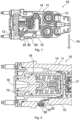
- FIG. 1 is a plan view of a brake signal transmitter 10 according to an embodiment of the invention.
- Figure 2 is a cross-sectional view of the brake signal transmitter 10.
- the brake signal transmitter 10 comprises a housing 11.
- the housing 11 comprises a first axial housing end 12 and a second axial housing end 13.
- the housing 11 comprises a circumferential housing wall 14.
- the circumferential housing wall 14 extends circumferentially around an axis 16 of the brake signal transmitter 10.
- the axis 16 may be an axis extending between a center if the first axial housing end 12 and a center of the second axial housing end 13.
- the axis 16 may be aligned with a center axis of a main coil spring 18 housed in the housing 11.
- a main valve 17 may be housed within the housing to provide pressure fluid (e.g., pressure gas) in response to an input received by the brake signal transmitter 10.
- the brake signal transmitter 10 may be configured to provide an electric output signal.
- a lower portion 15 of the circumferential housing wall 14 extends on the downward side of the housing 11.
- the terms “lower side” or “downward” are provided with reference to a gravitational force direction 19 when a vehicle comprising the brake signal transmitter 10 is located on a horizontal surface.
- the brake signal transmitter 10 comprises a liquid drainage system 20.
- the liquid drainage system 20 may be a gravity-driven liquid drainage system.
- the liquid drainage system 20 is provided at the portion 15 of the housing 11 which, in a horizontal installation orientation of the brake signal transmitter 10, faces downward relative to the gravitational force direction 19.
- the liquid drainage system 20 is configured to provide a water flow path 25 that allows water or other liquids to be discharged from an interior of the housing 11, driven by gravitational force.
- the liquid drainage system 20 is also configured to reduce or eliminate ingress of liquid and dirt (such as dust or other particulate matter) into the interior of the housing 11.
- a cap 30 is engaged with a flange 22 of the housing 11 to secure the cap 30 overlapping with an opening (the opening being designated by reference numeral 21 in Figures 4 and 12 ) of the housing 11.
- the cap 30 comprises one or several apertures to allow liquid to pass therethrough for liquid drainage from the housing 11.
- the liquid drainage system 20 may be configured in such a way that it provides a one-way flow path for liquid to permit water egress while reducing or eliminating liquid and/or particulate matter ingress into the housing 11.
- the liquid drainage system 20 may comprise a labyrinth seal configuration to implement such a one-way valve functionality.
- Figure 3 is a partially exploded perspective view of the brake signal transmitter 10.
- Figure 4 is a partially exploded detail view of the brake signal transmitter 10.
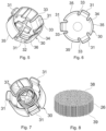
- Figure 5 is a perspective view of the cap 30 of the brake signal transmitter 10.
- Figure 6 is a plan view of the cap 30.
- Figure 7 is a perspective view of the cap 30 with a bias member 27 arranged thereon.
- Figure 8 is a perspective view of a filter 26 of a foreign matter ingress-reducing arrangement of the liquid drainage system 20.
- the liquid drainage system 20 comprises the cap 30, the opening 21 of the housing 11, and may optionally comprise additional components such as the bias member 27 which may be implemented by a compression spring and the filter 26 that further reduce the risk of ingress of liquid and/or dirt (i.e., particulate matter) into the housing 11.
- the opening 21 may be circular, without being limited thereto.
- the housing 11 comprises a flange 22 projecting outwardly from the lower portion 15. The flange 22 facilitates assembly of the cap 30, provides protection for the cap 30, and reduces the effective area through which liquid and/or dirt could potentially enter into the housing 11 against the gravity force.
- the cap 30 comprises one or several snap fingers 31 that form as resiliently deformable cover portions.
- Each of the snap fingers 31 has an engagement structure 32 at its end.
- the snap finger(s) 31 allow the cap 30 to be secured on the housing 11 by means of a snap fit.
- a mating retaining recess 23 into which the engagement projections 32 can snap is provided in an inner wall of the flange 22.
- the retaining recess 23 can be a circumferential recess that extends circumferentially along an entire inner circumference of the flange 22.
- the snap finger(s) 31 may be resiliently deformable so as to bend towards a center axis of the cap 30 when the cap 30 is inserted into the socket defined by the flange 22.
- the snap finger(s) 31 may be dimensioned and biased so as to snap into the retaining recess 23 upon insertion of the cap 30 into the housing socket surrounded by the flange 22.
- each snap finger 31 On both circumferential sides, each snap finger 31 may be spaced from an adjacent cylindrical segment 35 of the cap 30 by a gap 33.
- the gaps 33 may extend from the free ends of the fingers 31 to an end face 34 of the cap.
- the end face 34 of the cap may be dimensioned to cover all or at least most of the opening 21 in the housing as seen in plan view in a viewing direction perpendicular the end face 34.
- the bias member 27, which may be implemented as a coil spring 27, may bias the cap 30 such that the engagement projections 32 are forced against a rim of the circumferential recess 23. The risk of unintentional deflection of the snap finger(s) 31 and, thus, of unintentional dislodgment of the cap 30 is thereby mitigated.
- the coil spring 27 may be a compression spring.
- the coil spring 27 may be made of steel. Other implementations that provide shape memory may be used.
- the coil spring 27 may be a compression spring configured to provide the forces that reduce the risk of unintentional dislodgment of the cap 30 and/or the filter 26.
- the snap finger(s) 31 and preferably all of the cap 30 may be made of a plastic material. This allows weight to be kept low. Moreover, the force exerted by the snap finger(s) 31 of plastic material onto the flange 22 are so low that the flange 22 may be formed with a small thickness as compared to other fastening techniques, such as crimping. This also contributes to keeping the weight low.
- the plastic material may comprise a polyamide, such as a glass fiber reinforced polyamide such as PA6-GF30. By using a fiber reinforced polymeric material, such as polyamide, a desired strength is attained for the cap while keeping its weight low.
- cap 30 and the housing 11 may be configured such that the cap 30 is secured to the housing 11 by means of a press-fit or push-in connection.
- the cap 30 is respectively arranged so as to overlap the opening 21 to reduce the likelihood of foreign matter ingress into the housing 11 through the opening 21.
- the liquid drainage system 20 comprises the filter 26.
- the filter 26 may be or may comprise a sintered body.
- the filter 26 may comprise spheres and/or ellipsoids in a closed packing to further mitigate the risk of ingress of foreign matter (e.g., particulate matter such as dirt and/or liquid such as spray water) into the housing against the gravity force.
- the filter 26 may be or may comprise a bronze sintered body, without being limited thereto. Such a filter configuration provides a labyrinth-type liquid flow path and thereby reduces the risk of liquid and/or dirt entering the housing in a direction opposite to the gravity direction.
- the spring 27 may be arranged in such a way that it biases the cap 30 relative to the filter 26. Thereby, the engagement projections 32 are pushed against a rim of the circumferential recess 23, reducing the risk of unintentional dislodgment of the gap. Further, the filter 26 is pushed against an abutment surface 24 surrounding the opening 21 in a ring-shaped manner. Forcing the filter 26 against the abutment surface 24 by means of the spring 27 reduces the risk of the filter 26 being dislodged relative to the abutment surface 24 during use. Tight abutment of the filter 26 on the abutment surface reduces the formation of additional gaps through which water or dirt could enter the housing 11.
- a first spring end ring 28 of the spring acting as bias member abuts on the cap 30, and a second spring end ring 29 abuts on the filter 26.
- the cap 30 may comprise a spring positioning structure 36.
- the spring positioning structure 36 may comprise a plurality of arms having ends 37 dimensioned to fit into an end ring of the spring 27. Other positioning structures may be used to position the spring 27 centrally relative to the cap 30 and the filter 26.
- Figure 8 shows a perspective view of the filter 26 when the filter is formed as a sintered body.
- the filter 26 may have a generally cylindrical outer envelope.
- the filter 26 may have a first filter end face 38 on which the second spring end ring 29 abuts.
- the filter 26 may have a second filter end face 39 that abuts on the abutment surface 24 of the housing.
- Figure 9 and Figure 10 are detail views illustrating assembly of the cap 30 to the housing 11.
- the filter 26 is received, at least in part, within a skirt portion of the cap 30 formed by the resilient fingers 31 and the cylindrical surface segments 35.
- the resilient fingers 31 of the cap 30 being made of a plastic material (such as a glass fiber reinforced polymeric material, e.g., a glass fiber reinforced polyamide), an assembly force 40 is low.
- Figure 11 shows a detail view of the brake signal transmitter 10 when the cap 30 is assembled to the housing 11.
- a height 44 of the projecting cap portion 42 measured between the cap end face 34 and the flange end plane 41 at the free end of the flange 22, is less than a total height 43 of the cap, measured between the end face 34 and the free ends of the cylindrical portions 35.
- a ratio of the height 44 to the total height 43 may be 0.8 or less, 0.7 or less, 0.6 or less, or 0.5 or less.
- Figure 12 is a cross-sectional view of the liquid drainage system 20 when the cap 30 is assembled to the housing.
- the flange 22, the filter 26, the cylindrical segments 35 of the cap 30 and the resilient fingers 31 of the cap 30 provide a tortuous path 45 through which water can exit the housing 11 in a gravity-driven manner.
- the liquid (in particular water) passes through and out of the cap 30 at the gap 33 which forms an aperture for liquid egress.
- a labyrinth-type seal is provided that makes it unlikely for liquid (such as spray water) and/or dirt (i.e., particulate matter) to enter the housing through the liquid discharge system 20.
- FIG 13 is a schematic view of a vehicle 46.
- the vehicle 46 may be a commercial vehicle, such as a towing vehicle, a truck, a lorry, or a bus.
- the brake signal transmitter 10 may comprise an actuation device, which may be provided by a linkage 48 and/or brake pedal 47.
- the actuation device provides an input to the brake signal transmitter 10.
- the brake signal transmitter In response to the input, the brake signal transmitter generates a fluidic and/or electric signal that causes a brake 49 to be actuated in accordance with a magnitude by which the actuation device has been displaced by a driver.
- the brake signal transmitter 10 is arranged in the vehicle in such a manner that its axis 16 is transverse to the gravitational force direction when the vehicle 46 is on a horizontal surface.
- the housing 11 of the brake signal transmitter 10 is oriented such that the opening 21 of the liquid drainage system 20 faces downward, relative to the gravitational force direction, when the vehicle 46 is on a horizontal surface.
- Figure 14 is a flow chart of a method 50 of assembling the brake signal transmitter.
- the brake signal transmitter housing 11 is provided.
- the cover comprising at least the cap 30 is assembled so as to overlap the opening 21.
- the assembly may comprise arranging the filter 26 in a socket of the housing delimited by the flange 22 and arranging the spring 27 (which is an example of a bias member) between the cap 30 and the filter 26.
- a liquid drainage system comprises a filter as an element separate from and interposed between the cap and the housing
- the filter may be formed integrally with the housing or the cap.
- cover which is configured as a cap having a circular cap end face and a skirt portion extending from a circumference of the circular cap end face
- the cover may have other shapes configured to extend over or along the opening of the housing.
- a brake signal transmitter which comprises an actuation device, such as a brake pedal or linkage
- the brake signal transmitter may have other structural configurations useful for generating and providing an output (such as a fluidic and/or electric) responsive to an input (such as a mechanical movement of a device actuable by a driver).
- brake signal transmitter which is configured for gravity-driven liquid drainage when installed in a horizontal orientation
- the brake signal transmitter may also be operative to provide gravity-driven liquid drainage when installed in a vertical orientation.
- embodiments provide a brake signal transmitter having a mechanism for liquid drainage while reducing or eliminating the risk of ingress of liquid and/or dirt into the housing.
- the brake signal transmitter according to at least some embodiments allows liquid to be drained from the housing of the brake signal transmitter without requiring the brake signal transmitter to be necessarily mounted vertically.
- the brake signal transmitter according to at least some embodiments allows liquid to be drained from the housing while providing greater flexibility in mounting the brake signal transmitter, such as by enabling gravity-driven liquid drainage when the brake signal transmitter is mounted horizontally.
- the brake signal transmitter according to at least some embodiments is implemented using lightweight components which are designed in such a manner that a flange for receiving the cover does not need to be formed with a large thickness, which would add to the weight.
Landscapes
- Engineering & Computer Science (AREA)
- Mechanical Engineering (AREA)
- General Engineering & Computer Science (AREA)
- Transportation (AREA)
- Physics & Mathematics (AREA)
- Fluid Mechanics (AREA)
- Chemical & Material Sciences (AREA)
- Analytical Chemistry (AREA)
- Regulating Braking Force (AREA)
- Transmission Of Braking Force In Braking Systems (AREA)
Abstract
Description
- The invention relates to braking systems and components thereof. The invention relates in particular to a brake signal transmitter configured for use in a commercial vehicle. The invention also relates to a braking system comprising the brake signal transmitter and to a vehicle, in particular a commercial vehicle, comprising the brake signal transmitter or the braking system.
- Commercial vehicles, such as towing vehicles, trucks, lorries or buses, are equipped with braking systems that address the specific challenges encountered in commercial vehicles.
- Braking systems suitable for commercial vehicles may also comprise specific components such as brake signal transmitters adapted for the requirements of commercial vehicles. Examples of brake signal transmitters are disclosed in
EP 3 390 175 B1 ,EP 1 000 830 B1 , andEP 0 241 673 B2 . Such brake signal transmitters may be operative to generate fluidic (e.g., pneumatic) and/or electric signals required for the control of the electro-pneumatic braking system. - Temporary presence of a liquid in a housing of a brake signal transmitter may be acceptable. However, it is desirable that the liquid can be drained from the housing. Some brake signal transmitters are designed in such a manner that they facilitate liquid drainage when the brake signal transmitter is mounted vertically, i.e., along the gravity direction, when a vehicle in which the brake signal transmitter is installed is on a horizontal surface. However, it would be desirable for a brake signal transmitter to provide liquid drainage for at least one mounting orientation other than vertical. It would also be desirable for a brake signal transmitter to provide liquid drainage while reducing the risk that dirt (such as particulate matter) and/or liquid (such as spray water) enters the housing of the brake signal transmitter.
- It is an object of the invention to provide an improved brake signal transmitter. It is in particular an object of the invention to provide a brake signal transmitter which provides a mechanism for liquid drainage while reducing or eliminating the risk of ingress of liquid or dirt into the housing. It is also optionally an object of the invention to provide a brake signal transmitter which allows liquid to be drained from the housing of the brake signal transmitter without requiring the brake signal transmitter to be mounted such that its axis is aligned with the gravity direction when a vehicle comprising the brake signal transmitter is on a horizontal surface.
- According to the invention, a brake signal transmitter as recited in the independent claim is provided. The dependent claims define preferred or advantageous embodiments.
- A brake signal transmitter according to the invention comprises a housing and a liquid drainage system. The liquid drainage system comprises an opening in the housing. The liquid drainage system comprises a cover configured to extend over or along the opening. The cover comprises at least one aperture configured to allow a liquid to be drained through the cover.
- The brake signal transmitter according to the invention allows liquid to be drained from the housing. The liquid drainage system is specifically configured in such a manner that the risk of liquid (e.g., spray water) and/or dirt (i.e., particulate matter) entering the housing is mitigated. More particularly, the liquid drainage system comprises the cover which allows liquid to pass from the housing through the opening and the aperture(s) of the cover. At the same time, the cover reduces the risk of unintentional ingress of liquid and/or dirt into the housing.
- The cover may be mounted so as to substantially or fully overlap the opening. This configuration provides the effect that spray water or dirt impinging on the housing and the cover is unlikely tool into the housing through the opening.
- The cover may comprise a plastic material. This configuration provides the effect that the cover can be manufactured efficiently and has low weight.
- The plastic material may comprise a polyamide, e.g., a glass fiber reinforced polyamide such as PA6-GF30. This configuration provides the effect that the cover can be manufactured efficiently and has low weight.
- The cover may comprise an engagement structure configured for engagement with the housing. The engagement structure may comprise or may be made of the plastic material. This configuration provides the effect that a flange of the housing with which the engagement structure is engaged can be formed with lower wall thickness as compared to, e.g., a case in which the cover is crimped to the housing.
- The engagement structure may comprise at least one resiliently deformable cover portion. The at least one resiliently deformable cover portion may be configured for a snap-fit engagement with the housing. This configuration provides the effect that the cover can be mounted in a simple and efficient manner by means of a snap-fit engagement.
- The cover and the housing may be configured to be engaged by means of a press-fit connection or a push-in connection. This configuration provides the effect that the cover can be mounted in a simple and efficient manner.
- The at least one aperture may comprise gaps on opposite sides of the at least one resiliently deformable cover portion (such as an arm biased into an engagement position). This configuration provides the effect that the at least one an aperture has the double functionality of delimiting the at least one resiliently deformable cover portion and allowing liquid to pass to the outside.
- The housing may comprise a housing socket at the opening. The housing socket may have a flange that projects outwardly from a housing surface and a recessed portion recessed relative to the housing surface. The flange may comprise a cylindrical wall. This configuration provides the effect that secure mounting of the cover is facilitated. Forces caused by water jets, for example, are more likely to be absorbed by outer walls of the housing socket and are less likely to directly impinge onto the cover. The risk of inadvertent dislodgment of the cover is reduced.
- The cover may be configured to be inserted into the housing socket. This configuration provides the effect that secure mounting of the cover is facilitated. Forces caused by water jets, for example, are more likely to be absorbed by outer walls of the housing socket and are less likely to directly impinge onto the cover. The risk of unintentional displacement or dislodgment of the cover is thereby reduced further.
- The liquid drainage system may be configured to allow only a one-way flow through the liquid drainage system. Thus, a one-way valve functionality may be provided by the liquid drainage system. This configuration provides the effect that the risk of liquid and/or particulate matter ingress (such as dirt ingress) into the housing at the opening is reduced further.
- The brake signal transmitter may comprise a foreign matter ingress-reducing arrangement configured to reduce or eliminate foreign matter ingress (e.g., liquid and/or particulate matter ingress) through the opening into the housing. This configuration provides the effect that the risk of liquid and/or particulate matter ingress into the housing at the opening is reduced further.
- The foreign matter ingress-reducing arrangement may comprise a tortuous path, wherein the cover delimits at least a portion of the tortuous path. The tortuous path may extend from the opening in the housing to the aperture(s) in the cover. This configuration provides the effect that the cover, potentially in combination with other components such as an inner wall of the flange at the housing socket and/or a filter, defines a labyrinth-type seal that reduces the risk of foreign matter ingress through the opening.
- The foreign matter ingress-reducing arrangement may comprise a filter. This configuration provides the effect that the risk of liquid or dirt ingress into the housing is reduced further.
- The cover may comprise or may be a cap. The cap may comprise a skirt portion configured to receive at least a portion of the filter therein. This configuration provides the effect that secure mounting of the filter is facilitated. This has also the effect that the risk of foreign matter ingress (such as ingress of liquid and/or particulate matter) through the opening is reduced further by providing the filter within a skirt portion of the cap.
- The cap may comprise an end face from which the skirt portion projects. The end face may be a continuous plate dimensioned to overlap most, optionally all of the opening. This configuration provides the effect that the risk of liquid and/or particulate matter ingress through the opening is reduced further.
- The foreign matter ingress-reducing arrangement may comprise a resiliently deformable bias member configured to bias the filter and the cap away from each other. The resiliently deformable bias member may be configured to be interposed between the filter and the cover (e.g., the cap). The resiliently deformable bias member may comprise a compression spring. This configuration provides the effect that the filter can be secured in abutment with an abutment surface of the housing. The risk of gap formation between the filter and the housing, which could give rise to a risk of liquid and/or particulate matter ingress through the opening, is reduced.
- The filter may be integrally formed with the housing or the cover. This configuration provides the effect that assembly is simplified.
- The filter may comprise a sintered body. The filter may comprise or may be a sintered body formed of spheres or ellipsoids of a metal or metal alloy material. The spheres or ellipsoids may be arranged in a closed-packed structure. This configuration provides the effect that liquid and/or particulate matter ingress into the housing can be reduced further by providing a labyrinth flow path through the filter.
- The brake signal transmitter may be a unit configured to generate a pneumatic and/or electric signal indicative of an input. The input may be indicative of actuation of a brake pedal or of other braking actuation device that can be operated by a driver. This configuration provides the effect that the brake signal transmitter generates pneumatic and/or electric output as required for performing a braking operation in accordance with the input. The brake signal transmitter may be configured such that the input comprises a mechanical input. This configuration provides the effect that the brake signal transmitter can act as a transducer that translates a mechanical input, such as a pathway of a brake pedal movement, into a corresponding pneumatic and/or electric output as required for performing a braking operation in accordance with the input.
- The brake signal transmitter may comprise a main valve for a braking fluid, which may be a gaseous fluid or a braking liquid. This configuration provides the effect that the brake signal transmitter can generate a suitable fluidic pressure responsive to the input by actuation of the main valve.
- The brake signal transmitter may comprise an actuating device configured to enable actuation of the brake signal transmitter by a driver of a vehicle. This configuration provides the effect that the actuation device, such as a brake pedal or a linkage connected to the brake pedal, can be provided as part of the brake signal transmitter. Mounting of the brake signal transmitter and actuation device is facilitated thereby.
- The brake signal transmitter may comprise a pressure-producing device configured to generate a braking pressure in response to the actuation. This configuration provides the effect that the brake signal transmitter can be used for a fluidic braking system, such as a pneumatic or liquid-based braking system.
- The pressure-producing device being arranged in the housing. This configuration protects the pressure-producing device from foreign matter.
- The housing may comprise a first axial housing end, a second axial housing end, and a circumferential housing wall extending between the first axial housing end and the second axial housing end. The opening may be provided in the circumferential housing wall. This configuration provides the effect that liquid drainage through the opening is possible when the brake signal transmitter is mounted horizontally, i.e., when the first and second axial housing ends are spaced from each other along the gravity direction.
- The opening may be spaced from both the first axial housing end and the second axial housing end. This configuration provides the effect that liquid drainage is facilitated at an intermediate location between the first and second axial housing ends.
- The circumferential housing wall may have an inner diameter. The inner diameter may vary in a direction from the fist axial housing end to the second axial housing end. The opening may be provided in a portion of the circumferential housing wall where the inner diameter is maximum. This configuration provides the effect that gravity-driven liquid drainage is facilitated when the brake signal transmitter is mounted horizontally.
- The housing may comprise a mounting structure for mounting the brake signal transmitter on a commercial vehicle. The opening in the housing may be arranged relative to the mounting structure such that liquid is driven through the opening by the gravitational force when mounting the brake signal transmitter to the commercial vehicle and the commercial vehicle is positioned on a horizontal surface. This configuration provides the effect of implementing a gravity-driven liquid drainage system.
- The opening in the housing may be arranged on a downward portion of the housing relative to a gravitational force direction when mounting the brake signal transmitter to the commercial vehicle and the commercial vehicle is on a horizontal surface. This configuration provides the effect of implementing a gravity-driven liquid drainage system.
- The mounting structure may be configured to allow the brake signal transmitter to be mounted such that an axis of the brake signal transmitter is transverse to a gravitational force direction, e.g., perpendicular to the gravitational force direction, when the commercial vehicle stands on a horizontal surface. The axis of the brake signal transmitter may be defined by or aligned with a center axis of a coil spring (such as a main coil spring of a brake signal transmitter main valve) of the brake signal transmitter. This configuration provides the effect that the brake signal transmitter is installable in a horizontal orientation while providing liquid drainage and reducing the risk of liquid and/or particulate matter ingress through the opening.
- The mounting structure may be configured to allow the brake signal transmitter to be installed in a vertical orientation (with the axis of the brake signal transmitter being parallel to the gravitational force direction when the commercial vehicle stands on a horizontal surface) and in the horizontal orientation (with the axis of the brake signal transmitter being perpendicular to the gravitational force direction when the commercial vehicle stands on a horizontal surface).
- A braking system according to an embodiment comprises the brake signal transmitter according to any embodiment disclosed herein. The braking system provides liquid drainage from the brake signal transmitter while reducing or eliminating the risk of liquid and/or dirt ingress into the housing through the opening.
- The braking system may be an electronic braking system (EBS), without being limited thereto.
- A vehicle according to an embodiment may comprise the brake signal transmitter according to any embodiment or the braking system according to any embodiment. The braking system provides liquid drainage from the brake signal transmitter while reducing or eliminating the risk of liquid and/or dirt ingress into the housing through the opening.
- The vehicle may be a commercial vehicle, such as a towing vehicle, a truck, a lorry or a bus.
- The vehicle is configured such that the opening of the housing is arranged on a downward side of the housing relative to a gravitational force direction when the vehicle is on a horizontal surface. This configuration provides the effect of implementing a gravity-driven liquid drainage system.
- According to another embodiment, there is provided a method of assembling the brake signal transmitter of any embodiment, comprising assembling the cover at the opening of the housing. The method may further comprise mounting the brake signal transmitter on a vehicle such that the liquid drainage system is at a lower side, relative to a gravitational force, of the housing when the vehicle is on a horizontal surface.
- According to another embodiment, there is provided a use of the brake signal transmitter of any embodiment mounted in a vehicle for providing liquid drainage from the housing of the brake signal transmitter and reducing liquid and/or particulate matter ingress into the housing.
- Various effects and advantages are attained by embodiments of the invention. Liquid drainage from the housing of the brake signal transmitter is provided while reducing the risk of liquid and/or dirt ingress into the housing through the opening of the liquid drainage system. The provision of a cover, such as a cap, comprising a plastic material (such as plastic engagement finger(s) for a snap-fit connection to the housing, or a cover engagement structure formed of a plastic material for a press-fit or push-in connection with the housing), provides ease of assembly, low weight, and reduces the requirements imposed on the structure of the housing with which the cover is engaged as compared to, e.g., an attachment of a metal cap by means of crimping.
- Further advantages and embodiments and developments are defined in the depended claims. These and other aspects of the invention will be apparent from and elucidated with reference to the embodiments described hereafter with reference to the accompanying drawings, in which:
-
Figure 1 is a plan view of a brake signal transmitter according to an embodiment of the invention. -
Figure 2 is a cross-sectional view of the brake signal transmitter. -
Figure 3 is a partially exploded perspective view of the brake signal transmitter. -
Figure 4 is a partially exploded detail view of the brake signal transmitter. -
Figure 5 is a perspective view of a cap of the brake signal transmitter. -
Figure 6 is a plan view of the cap. -
Figure 7 is a perspective view of the cap with a bias member arranged thereon. -
Figure 8 is a perspective view of a filter of a foreign matter ingress-reducing arrangement. -
Figure 9 is a perspective detail view illustrating assembly of the cap to a housing of the brake signal transmitter. -
Figure 10 is a perspective detail view illustrating the cap assembled to the housing of the brake signal transmitter. -
Figure 11 is a side view illustrating the cap assembled to the housing of the brake signal transmitter. -
Figure 12 is a cross-sectional view along line XII-XII inFigure 10 . -
Figure 13 is a schematic view of a commercial vehicle comprising the brake signal transmitter. -
Figure 14 is a flow chart of a method of assembling the brake signal transmitter. - Embodiments of the invention will be described with reference to the drawings. In the drawings, similar or identical reference signs designate elements with similar or identical configuration and/or function.
- Embodiments of the invention relate to a brake signal transmitter as well as a brake system and vehicle comprising the brake signal transmitter. As used herein, the term "brake signal transmitter" refers to a device configured to receive an input and provide an output indicative of a desired braking action. The output may be pneumatic, electric, or both, without being limited thereto. The input may be a mechanical input, which may be obtained from a brake pedal or a linkage connected to the brake pedal or another actuation device.
-
Figure 1 is a plan view of abrake signal transmitter 10 according to an embodiment of the invention.Figure 2 is a cross-sectional view of thebrake signal transmitter 10. Thebrake signal transmitter 10 comprises ahousing 11. Thehousing 11 comprises a firstaxial housing end 12 and a secondaxial housing end 13. Thehousing 11 comprises acircumferential housing wall 14. Thecircumferential housing wall 14 extends circumferentially around anaxis 16 of thebrake signal transmitter 10. Theaxis 16 may be an axis extending between a center if the firstaxial housing end 12 and a center of the secondaxial housing end 13. Theaxis 16 may be aligned with a center axis of amain coil spring 18 housed in thehousing 11. Amain valve 17 may be housed within the housing to provide pressure fluid (e.g., pressure gas) in response to an input received by thebrake signal transmitter 10. Alternatively or additionally to providing a fluidic output, thebrake signal transmitter 10 may be configured to provide an electric output signal. - When the
brake signal transmitter 10 is mounted, alower portion 15 of thecircumferential housing wall 14 extends on the downward side of thehousing 11. As used herein, the terms "lower side" or "downward" are provided with reference to agravitational force direction 19 when a vehicle comprising thebrake signal transmitter 10 is located on a horizontal surface. - The
brake signal transmitter 10 comprises aliquid drainage system 20. Theliquid drainage system 20 may be a gravity-driven liquid drainage system. Theliquid drainage system 20 is provided at theportion 15 of thehousing 11 which, in a horizontal installation orientation of thebrake signal transmitter 10, faces downward relative to thegravitational force direction 19. Theliquid drainage system 20 is configured to provide a water flow path 25 that allows water or other liquids to be discharged from an interior of thehousing 11, driven by gravitational force. Theliquid drainage system 20 is also configured to reduce or eliminate ingress of liquid and dirt (such as dust or other particulate matter) into the interior of thehousing 11. Acap 30 is engaged with aflange 22 of thehousing 11 to secure thecap 30 overlapping with an opening (the opening being designated byreference numeral 21 inFigures 4 and12 ) of thehousing 11. Thecap 30 comprises one or several apertures to allow liquid to pass therethrough for liquid drainage from thehousing 11. As will be explained in more detail below, theliquid drainage system 20 may be configured in such a way that it provides a one-way flow path for liquid to permit water egress while reducing or eliminating liquid and/or particulate matter ingress into thehousing 11. Theliquid drainage system 20 may comprise a labyrinth seal configuration to implement such a one-way valve functionality. - A configuration of the
liquid drainage system 20 of thebrake signal transmitter 10 will be explained in more detail with reference toFigures 3 to 12 .Figure 3 is a partially exploded perspective view of thebrake signal transmitter 10.Figure 4 is a partially exploded detail view of thebrake signal transmitter 10.Figure 5 is a perspective view of thecap 30 of thebrake signal transmitter 10.Figure 6 is a plan view of thecap 30. -
Figure 7 is a perspective view of thecap 30 with abias member 27 arranged thereon.Figure 8 is a perspective view of afilter 26 of a foreign matter ingress-reducing arrangement of theliquid drainage system 20. - The
liquid drainage system 20 comprises thecap 30, theopening 21 of thehousing 11, and may optionally comprise additional components such as thebias member 27 which may be implemented by a compression spring and thefilter 26 that further reduce the risk of ingress of liquid and/or dirt (i.e., particulate matter) into thehousing 11. Theopening 21 may be circular, without being limited thereto. Thehousing 11 comprises aflange 22 projecting outwardly from thelower portion 15. Theflange 22 facilitates assembly of thecap 30, provides protection for thecap 30, and reduces the effective area through which liquid and/or dirt could potentially enter into thehousing 11 against the gravity force. - The
cap 30 comprises one or severalsnap fingers 31 that form as resiliently deformable cover portions. Each of thesnap fingers 31 has anengagement structure 32 at its end. The snap finger(s) 31 allow thecap 30 to be secured on thehousing 11 by means of a snap fit. Amating retaining recess 23 into which theengagement projections 32 can snap is provided in an inner wall of theflange 22. The retainingrecess 23 can be a circumferential recess that extends circumferentially along an entire inner circumference of theflange 22. The snap finger(s) 31 may be resiliently deformable so as to bend towards a center axis of thecap 30 when thecap 30 is inserted into the socket defined by theflange 22. The snap finger(s) 31 may be dimensioned and biased so as to snap into the retainingrecess 23 upon insertion of thecap 30 into the housing socket surrounded by theflange 22. On both circumferential sides, eachsnap finger 31 may be spaced from an adjacentcylindrical segment 35 of thecap 30 by agap 33. Thegaps 33 may extend from the free ends of thefingers 31 to anend face 34 of the cap. The end face 34 of the cap may be dimensioned to cover all or at least most of theopening 21 in the housing as seen in plan view in a viewing direction perpendicular theend face 34. - The
bias member 27, which may be implemented as acoil spring 27, may bias thecap 30 such that theengagement projections 32 are forced against a rim of thecircumferential recess 23. The risk of unintentional deflection of the snap finger(s) 31 and, thus, of unintentional dislodgment of thecap 30 is thereby mitigated. - The
coil spring 27 may be a compression spring. Thecoil spring 27 may be made of steel. Other implementations that provide shape memory may be used. Thecoil spring 27 may be a compression spring configured to provide the forces that reduce the risk of unintentional dislodgment of thecap 30 and/or thefilter 26. - The snap finger(s) 31 and preferably all of the
cap 30 may be made of a plastic material. This allows weight to be kept low. Moreover, the force exerted by the snap finger(s) 31 of plastic material onto theflange 22 are so low that theflange 22 may be formed with a small thickness as compared to other fastening techniques, such as crimping. This also contributes to keeping the weight low. The plastic material may comprise a polyamide, such as a glass fiber reinforced polyamide such as PA6-GF30. By using a fiber reinforced polymeric material, such as polyamide, a desired strength is attained for the cap while keeping its weight low. - While a snap-fit coupling of the
cap 30 and thehousing 11 has been explained above, other configurations may be used in accordance with the invention for securing thecap 30 to thehousing 11. For illustration, thecap 30 and thehousing 11 may be configured such that thecap 30 is secured to thehousing 11 by means of a press-fit or push-in connection. Thecap 30 is respectively arranged so as to overlap theopening 21 to reduce the likelihood of foreign matter ingress into thehousing 11 through theopening 21. - The
liquid drainage system 20 comprises thefilter 26. Thefilter 26 may be or may comprise a sintered body. Thefilter 26 may comprise spheres and/or ellipsoids in a closed packing to further mitigate the risk of ingress of foreign matter (e.g., particulate matter such as dirt and/or liquid such as spray water) into the housing against the gravity force. Thefilter 26 may be or may comprise a bronze sintered body, without being limited thereto. Such a filter configuration provides a labyrinth-type liquid flow path and thereby reduces the risk of liquid and/or dirt entering the housing in a direction opposite to the gravity direction. - The
spring 27 may be arranged in such a way that it biases thecap 30 relative to thefilter 26. Thereby, theengagement projections 32 are pushed against a rim of thecircumferential recess 23, reducing the risk of unintentional dislodgment of the gap. Further, thefilter 26 is pushed against anabutment surface 24 surrounding theopening 21 in a ring-shaped manner. Forcing thefilter 26 against theabutment surface 24 by means of thespring 27 reduces the risk of thefilter 26 being dislodged relative to theabutment surface 24 during use. Tight abutment of thefilter 26 on the abutment surface reduces the formation of additional gaps through which water or dirt could enter thehousing 11. In the assembledbrake signal transmitter 10, a firstspring end ring 28 of the spring acting as bias member abuts on thecap 30, and a secondspring end ring 29 abuts on thefilter 26. - The
cap 30 may comprise aspring positioning structure 36. Thespring positioning structure 36 may comprise a plurality of arms having ends 37 dimensioned to fit into an end ring of thespring 27. Other positioning structures may be used to position thespring 27 centrally relative to thecap 30 and thefilter 26. -
Figure 8 shows a perspective view of thefilter 26 when the filter is formed as a sintered body. Thefilter 26 may have a generally cylindrical outer envelope. Thefilter 26 may have a first filter end face 38 on which the secondspring end ring 29 abuts. Thefilter 26 may have a second filter end face 39 that abuts on theabutment surface 24 of the housing. -
Figure 9 and Figure 10 are detail views illustrating assembly of thecap 30 to thehousing 11. Thefilter 26 is received, at least in part, within a skirt portion of thecap 30 formed by theresilient fingers 31 and thecylindrical surface segments 35. With at least theresilient fingers 31 of thecap 30 being made of a plastic material (such as a glass fiber reinforced polymeric material, e.g., a glass fiber reinforced polyamide), anassembly force 40 is low. -
Figure 11 shows a detail view of thebrake signal transmitter 10 when thecap 30 is assembled to thehousing 11. When assembled, only aportion 42 of thecap 30 projects outwardly from an outerflange end plane 41 of theflange 22. Aheight 44 of the projectingcap portion 42, measured between thecap end face 34 and theflange end plane 41 at the free end of theflange 22, is less than atotal height 43 of the cap, measured between theend face 34 and the free ends of thecylindrical portions 35. Thereby, the exposed parts of thegaps 33 that project outwardly beyond theflange end plane 41 make it even more challenging for liquid and/or dirt to enter the housing against the action of gravity. In some implementations, a ratio of theheight 44 to thetotal height 43 may be 0.8 or less, 0.7 or less, 0.6 or less, or 0.5 or less. -
Figure 12 is a cross-sectional view of theliquid drainage system 20 when thecap 30 is assembled to the housing. Theflange 22, thefilter 26, thecylindrical segments 35 of thecap 30 and theresilient fingers 31 of thecap 30 provide atortuous path 45 through which water can exit thehousing 11 in a gravity-driven manner. The liquid (in particular water) passes through and out of thecap 30 at thegap 33 which forms an aperture for liquid egress. At the same time, a labyrinth-type seal is provided that makes it unlikely for liquid (such as spray water) and/or dirt (i.e., particulate matter) to enter the housing through theliquid discharge system 20. -
Figure 13 is a schematic view of avehicle 46. Thevehicle 46 may be a commercial vehicle, such as a towing vehicle, a truck, a lorry, or a bus. Thebrake signal transmitter 10 may comprise an actuation device, which may be provided by alinkage 48 and/orbrake pedal 47. The actuation device provides an input to thebrake signal transmitter 10. In response to the input, the brake signal transmitter generates a fluidic and/or electric signal that causes abrake 49 to be actuated in accordance with a magnitude by which the actuation device has been displaced by a driver. - As schematically shown in
Figure 13 , thebrake signal transmitter 10 is arranged in the vehicle in such a manner that itsaxis 16 is transverse to the gravitational force direction when thevehicle 46 is on a horizontal surface. - As schematically shown in
Figure 13 , thehousing 11 of thebrake signal transmitter 10 is oriented such that theopening 21 of theliquid drainage system 20 faces downward, relative to the gravitational force direction, when thevehicle 46 is on a horizontal surface. -
Figure 14 is a flow chart of amethod 50 of assembling the brake signal transmitter. Atprocess block 51, the brakesignal transmitter housing 11 is provided. Atprocess block 52, the cover comprising at least thecap 30 is assembled so as to overlap theopening 21. The assembly may comprise arranging thefilter 26 in a socket of the housing delimited by theflange 22 and arranging the spring 27 (which is an example of a bias member) between thecap 30 and thefilter 26. - While embodiments have been described with reference to the drawings, modifications and alterations may be implemented in other embodiments.
- For illustration, while embodiments have been described in which a liquid drainage system comprises a filter as an element separate from and interposed between the cap and the housing, the filter may be formed integrally with the housing or the cap.
- For further illustration, while a cover has been described which is configured as a cap having a circular cap end face and a skirt portion extending from a circumference of the circular cap end face, the cover may have other shapes configured to extend over or along the opening of the housing.
- For further illustration, while a cover engageable or engaged with the housing by means of a snap-fit connection has been described, other engagement techniques can be used. In particular, other techniques which allow the cover (e.g., the cap) to be directly engaged with and secured on the housing without requiring a fastening element different from the cap and the housing afford ease of assembly. Such techniques include, without limitation, a press-fit or push-in connection.
- For further illustration, while a brake signal transmitter has been described which comprises an actuation device, such as a brake pedal or linkage, the brake signal transmitter may have other structural configurations useful for generating and providing an output (such as a fluidic and/or electric) responsive to an input (such as a mechanical movement of a device actuable by a driver).
- For further illustration, while a brake signal transmitter has been described which is configured for gravity-driven liquid drainage when installed in a horizontal orientation, the brake signal transmitter may also be operative to provide gravity-driven liquid drainage when installed in a vertical orientation.
- Various effects and advantages are attained by embodiments of the invention. For illustration, embodiments provide a brake signal transmitter having a mechanism for liquid drainage while reducing or eliminating the risk of ingress of liquid and/or dirt into the housing. The brake signal transmitter according to at least some embodiments allows liquid to be drained from the housing of the brake signal transmitter without requiring the brake signal transmitter to be necessarily mounted vertically. The brake signal transmitter according to at least some embodiments allows liquid to be drained from the housing while providing greater flexibility in mounting the brake signal transmitter, such as by enabling gravity-driven liquid drainage when the brake signal transmitter is mounted horizontally. The brake signal transmitter according to at least some embodiments is implemented using lightweight components which are designed in such a manner that a flange for receiving the cover does not need to be formed with a large thickness, which would add to the weight.
-
- 10
- brake signal transmitter
- 11
- housing
- 12
- first axial housing end
- 13
- second axial housing end
- 14
- circumferential housing wall
- 15
- lower portion of circumferential housing wall
- 16
- housing axis
- 17
- brake signal transmitter main valve
- 18
- brake signal transmitter main coil spring
- 19
- gravitational force direction
- 20
- liquid drainage system
- 21
- opening
- 22
- flange
- 23
- retaining recess
- 24
- abutment surface
- 25
- water flow path
- 26
- filter
- 27
- spring
- 28
- first spring end ring
- 29
- second spring end ring
- 30
- cap
- 31
- resilient portion
- 32
- engagement projection
- 33
- gap
- 34
- cap end face
- 35
- cap cylindrical segment
- 36
- spring positioning structure
- 37
- ends of spring positioning structure
- 38
- first filter end face
- 39
- second filter end face
- 40
- assembly force
- 41
- flange end plane
- 42
- projecting cap portion
- 43
- cap height
- 44
- projecting cap height
- 45
- tortuous path
- 46
- vehicle
- 47
- brake pedal
- 48
- linkage
- 49
- brake
- 50
- method
- 51
- process block
- 52
- process block
Claims (15)
- A brake signal transmitter (10), comprising:a housing (11); anda liquid drainage system (20), comprisingan opening (21) in the housing (11) anda cover (30) configured to extend over or along the opening (21);wherein the cover (30) comprises at least one aperture (33) configured to allow a liquid to be drained through the cover (30).
- The brake signal transmitter (10) of claim 1, wherein the cover (30) comprises a plastic material.
- The brake signal transmitter (10) of claim 2, wherein the cover (30) comprises an engagement structure (31, 32) configured for engagement with the housing (11), wherein the engagement structure (31, 32) comprises or is made of the plastic material.
- The brake signal transmitter (10) of claim 3, wherein the engagement structure (31, 32) comprises at least one resiliently deformable cover portion (31), wherein the at least one resiliently deformable cover portion (31) is configured for a snap-fit engagement with the housing (20).
- The brake signal transmitter (10) of claim 4, wherein the at least one aperture (33) comprises gaps (33) on opposite sides of the at least one resiliently deformable cover portion (31).
- The brake signal transmitter (10) of any one of the preceding claims, wherein the housing (11) comprises a housing socket (22) at the opening (21).
- The brake signal transmitter (10) of claim 6, wherein the cover (30) is configured to be inserted into the housing socket (22).
- The brake signal transmitter (10) of any one of the preceding claims, wherein the brake signal transmitter (10) comprises a foreign matter ingress-reducing arrangement (24, 26, 37) configured to reduce or eliminate foreign matter ingress through the opening (21) into the housing (11).
- The brake signal transmitter (10) of claim 8, wherein the foreign matter ingress-reducing arrangement (24, 26, 37) comprises a tortuous path (45), wherein the cover (30) delimits at least a portion of the tortuous path (45).
- The brake signal transmitter (10) of claim 8 or claim 9, wherein the foreign matter ingress-reducing arrangement (24, 26, 37) comprises a filter (26).
- The brake signal transmitter (10) of claim 10, wherein the cover (30) comprises a cap (30), wherein the cap (30) comprises a skirt portion (31, 35) configured to receive at least a portion of the filter (26) therein.
- The brake signal transmitter (10) of claim 10 or claim 11, whereinthe foreign matter ingress-reducing arrangement (24, 26, 37) comprises a resiliently deformable bias member (37) configured to bias the filter (26) and the cover (30) away from each other, wherein the resiliently deformable bias member (37) is configured to be interposed between the filter (26) and the cover (30); orthe filter (26) is integrally formed with the housing (11) or the cover (30).
- The brake signal transmitter (10) of any one of the preceding claims, further comprising:an actuating device (47) configured to enable actuation of the brake signal transmitter (10) by a driver of a vehicle, anda pressure-producing device (17, 18) configured to generate a braking pressure in response to the actuation, the pressure-producing device (17, 18) being arranged in the housing (11).
- A braking system (10, 47, 48, 49), comprising the brake signal transmitter (10) of any one of the preceding claims.
- A vehicle (46), comprising the brake signal transmitter (10) of any one of claims 1 to 13 or the braking system (10, 47, 48, 49) of claim 14, wherein the opening (21) of the housing (11) is arranged on a downward side of the housing (11) relative to a gravitational force direction (19) when the vehicle (46) is on a horizontal surface.
Priority Applications (3)
| Application Number | Priority Date | Filing Date | Title |
|---|---|---|---|
| EP23171078.1A EP4458630B1 (en) | 2023-05-02 | 2023-05-02 | Brake signal transmitter, braking system, and vehicle |
| CN202410466737.6A CN118894077A (en) | 2023-05-02 | 2024-04-18 | Brake signal transmitter, brake system and vehicle |
| US18/650,494 US12606143B2 (en) | 2023-05-02 | 2024-04-30 | Brake signal transmitter, braking system, and vehicle |
Applications Claiming Priority (1)
| Application Number | Priority Date | Filing Date | Title |
|---|---|---|---|
| EP23171078.1A EP4458630B1 (en) | 2023-05-02 | 2023-05-02 | Brake signal transmitter, braking system, and vehicle |
Publications (2)
| Publication Number | Publication Date |
|---|---|
| EP4458630A1 true EP4458630A1 (en) | 2024-11-06 |
| EP4458630B1 EP4458630B1 (en) | 2025-12-24 |
Family
ID=86328476
Family Applications (1)
| Application Number | Title | Priority Date | Filing Date |
|---|---|---|---|
| EP23171078.1A Active EP4458630B1 (en) | 2023-05-02 | 2023-05-02 | Brake signal transmitter, braking system, and vehicle |
Country Status (3)
| Country | Link |
|---|---|
| US (1) | US12606143B2 (en) |
| EP (1) | EP4458630B1 (en) |
| CN (1) | CN118894077A (en) |
Citations (11)
| Publication number | Priority date | Publication date | Assignee | Title |
|---|---|---|---|---|
| US4855041A (en) * | 1987-04-24 | 1989-08-08 | Parker Hannifin Corporation | Fluid filter drain assembly |
| EP0241673B2 (en) | 1986-04-09 | 1993-11-10 | WABCO Vermögensverwaltungs-GmbH | Brake control adjuster |
| GB2304839A (en) * | 1995-09-06 | 1997-03-26 | Rover Group | Coupling cap for vacuum bleeding equipment for a vehicle hydraulic brake system |
| US5947239A (en) * | 1996-08-26 | 1999-09-07 | Haldex Financial Services Corporation | Contaminant-ejecting relay valve for a pneumatic brake system |
| GB2371351A (en) * | 2000-11-17 | 2002-07-24 | Luk Lamellen & Kupplungsbau | Bleed valve |
| EP1000830B1 (en) | 1998-11-13 | 2003-07-09 | WABCO GmbH & Co. OHG | Brake control adjuster with integrated adding redundancy |
| US20050167351A1 (en) * | 2004-01-29 | 2005-08-04 | Herman Peter K. | Liquid additive slow-release apparatus driven by a filter pressure gradient |
| US20150314761A1 (en) * | 2012-12-12 | 2015-11-05 | Vhit S.P.A. | Hydraulic braking system for farm tractors or the like and method of managing such system |
| EP3390175B1 (en) | 2015-12-19 | 2019-08-21 | WABCO GmbH | Piston guide in housing cover, and use of such a cover in a pneumatic brake drivers valve |
| PL236795B1 (en) * | 2019-02-03 | 2021-02-22 | Mb Pneumatyka Spolka Z Ograniczona Odpowiedzialnoscia | Automatic drain valve for draining compressed air tanks |
| US11603942B2 (en) * | 2020-08-06 | 2023-03-14 | Illinois Tool Works Inc. | Valve assembly and housing comprising the same |
Family Cites Families (19)
| Publication number | Priority date | Publication date | Assignee | Title |
|---|---|---|---|---|
| US1805658A (en) * | 1928-08-21 | 1931-05-19 | Westinghouse Air Brake Co | Triple valve cylinder cap |
| US1935813A (en) * | 1931-03-21 | 1933-11-21 | Westinghouse Air Brake Co | Air strainer |
| US2197092A (en) * | 1939-08-31 | 1940-04-16 | New York Air Brake Co | Air brake |
| US2572311A (en) * | 1950-03-08 | 1951-10-23 | Francis W Burd | Moisture eliminating device for compressed-air systems |
| US2859763A (en) * | 1957-02-28 | 1958-11-11 | Wagner Electric Corp | Tractor protector valve |
| US2962119A (en) * | 1957-07-08 | 1960-11-29 | Wagner Electric Corp | Filter unit |
| US2958394A (en) * | 1957-09-23 | 1960-11-01 | John B Woodmansee | Automatic moisture extractor for compressed air lines |
| US3748837A (en) * | 1971-01-18 | 1973-07-31 | Sloan Valve Co | Combination cut-out cock and dirt collectors |
| BE789567A (en) * | 1971-09-30 | 1973-03-29 | Norgren Ltd C A | PERFECTIONED VALVE SERVING TO PURGE COMPRESSED GAS OF LIQUIDS WHICH POLLUTE IT |
| CA1043275A (en) * | 1974-04-20 | 1978-11-28 | Hans-Joachim Hofmann | Apparatus for producing dry compressed air |
| US4141379A (en) * | 1977-05-16 | 1979-02-27 | Cutter Laboratories, Inc. | Check valve |
| DE3243199A1 (en) * | 1982-11-23 | 1984-07-05 | Festo-Maschinenfabrik Gottlieb Stoll, 7300 Esslingen | SOLENOID VALVE UNIT |
| US5600953A (en) * | 1994-09-28 | 1997-02-11 | Aisin Seiki Kabushiki Kaisha | Compressed air control apparatus |
| CA2530807C (en) * | 2003-08-25 | 2012-04-24 | Bendix Commercial Vehicle Systems Llc | Drain valve |
| US9010365B2 (en) * | 2008-05-21 | 2015-04-21 | Parker-Hannifin Corporation | Breather with independent inlet/outlet flow paths |
| US20140209620A1 (en) * | 2013-01-31 | 2014-07-31 | Kyle Steven Barna | Drain Nut |
| US9259681B2 (en) * | 2013-10-31 | 2016-02-16 | Haldex Brake Products Corporation | Air dryer |
| EP3617016B1 (en) * | 2014-10-28 | 2021-03-10 | Parker-Hannificn Corporation | Combined oil and water separator in an air brake dryer |
| US10583391B2 (en) * | 2017-12-18 | 2020-03-10 | Bendix Commercial Vehicle Systems Llc | Absorbent apparatus for an air dryer purge air cleaner and method of producing the same |
-
2023
- 2023-05-02 EP EP23171078.1A patent/EP4458630B1/en active Active
-
2024
- 2024-04-18 CN CN202410466737.6A patent/CN118894077A/en active Pending
- 2024-04-30 US US18/650,494 patent/US12606143B2/en active Active
Patent Citations (11)
| Publication number | Priority date | Publication date | Assignee | Title |
|---|---|---|---|---|
| EP0241673B2 (en) | 1986-04-09 | 1993-11-10 | WABCO Vermögensverwaltungs-GmbH | Brake control adjuster |
| US4855041A (en) * | 1987-04-24 | 1989-08-08 | Parker Hannifin Corporation | Fluid filter drain assembly |
| GB2304839A (en) * | 1995-09-06 | 1997-03-26 | Rover Group | Coupling cap for vacuum bleeding equipment for a vehicle hydraulic brake system |
| US5947239A (en) * | 1996-08-26 | 1999-09-07 | Haldex Financial Services Corporation | Contaminant-ejecting relay valve for a pneumatic brake system |
| EP1000830B1 (en) | 1998-11-13 | 2003-07-09 | WABCO GmbH & Co. OHG | Brake control adjuster with integrated adding redundancy |
| GB2371351A (en) * | 2000-11-17 | 2002-07-24 | Luk Lamellen & Kupplungsbau | Bleed valve |
| US20050167351A1 (en) * | 2004-01-29 | 2005-08-04 | Herman Peter K. | Liquid additive slow-release apparatus driven by a filter pressure gradient |
| US20150314761A1 (en) * | 2012-12-12 | 2015-11-05 | Vhit S.P.A. | Hydraulic braking system for farm tractors or the like and method of managing such system |
| EP3390175B1 (en) | 2015-12-19 | 2019-08-21 | WABCO GmbH | Piston guide in housing cover, and use of such a cover in a pneumatic brake drivers valve |
| PL236795B1 (en) * | 2019-02-03 | 2021-02-22 | Mb Pneumatyka Spolka Z Ograniczona Odpowiedzialnoscia | Automatic drain valve for draining compressed air tanks |
| US11603942B2 (en) * | 2020-08-06 | 2023-03-14 | Illinois Tool Works Inc. | Valve assembly and housing comprising the same |
Also Published As
| Publication number | Publication date |
|---|---|
| US20240367632A1 (en) | 2024-11-07 |
| CN118894077A (en) | 2024-11-05 |
| EP4458630B1 (en) | 2025-12-24 |
| US12606143B2 (en) | 2026-04-21 |
Similar Documents
| Publication | Publication Date | Title |
|---|---|---|
| AU648589B2 (en) | A tamper-resistant brake actuator and a method of forming a tamper-resistant brake actuator | |
| US20110094481A1 (en) | Exhaust gas recirculation valve device | |
| US20110170260A1 (en) | Housing structure for vehicle electronic control unit | |
| US6006651A (en) | Spring brake actuator with filtered service vent opening | |
| EP1624154B1 (en) | Brake actuator | |
| WO2004099749A1 (en) | Pressure equalisation device | |
| US9586567B2 (en) | Spring brake cylinder having combined inlet and outlet diaphragm valve | |
| US20020170427A1 (en) | Apparatus and method of attaching a connecting member and a tube member to a housing of a vacuum brake booster | |
| EP4458630A1 (en) | Brake signal transmitter, braking system, and vehicle | |
| EP0086060A1 (en) | Shipping and installation strap for linear actuator | |
| US7331571B2 (en) | Integrated solenoid valve and air spring assembly | |
| US10814682B2 (en) | System for monitoring tire pressure and method for mounting a tire pressure monitoring system on a rim | |
| US4419923A (en) | Toggle assembly for vehicles or cars | |
| US7201045B2 (en) | Pressure sensor module | |
| WO1999063203A1 (en) | Easy fit diaphragm | |
| US7918484B2 (en) | Vehicle body seal for a steering column leadthrough | |
| AU689863B2 (en) | Spring brake actuator with filtered vent openings | |
| US20230365112A1 (en) | Brake actuator for a vehicle including a cylinder and dust plug | |
| US10539221B2 (en) | Casing structure of vehicular power transmitting device | |
| US6405636B1 (en) | Brake actuation having snap-fit tamper resistant spring chamber | |
| US20240101091A1 (en) | Automotive air pressure spring brake chamber having caging bolt assembly | |
| US7010913B2 (en) | Braking system, in particular for a motor vehicle | |
| JP4910929B2 (en) | shock absorber | |
| CN116135629A (en) | Exhaust of housings for electronic components of pneumatic devices | |
| EP4292894A1 (en) | Spring brake actuator comprising flexible segments for providing a snap-fit connection, and commercial vehicle comprising a respective spring brake actuator |
Legal Events
| Date | Code | Title | Description |
|---|---|---|---|
| PUAI | Public reference made under article 153(3) epc to a published international application that has entered the european phase |
Free format text: ORIGINAL CODE: 0009012 |
|
| STAA | Information on the status of an ep patent application or granted ep patent |
Free format text: STATUS: THE APPLICATION HAS BEEN PUBLISHED |
|
| AK | Designated contracting states |
Kind code of ref document: A1 Designated state(s): AL AT BE BG CH CY CZ DE DK EE ES FI FR GB GR HR HU IE IS IT LI LT LU LV MC ME MK MT NL NO PL PT RO RS SE SI SK SM TR |
|
| STAA | Information on the status of an ep patent application or granted ep patent |
Free format text: STATUS: REQUEST FOR EXAMINATION WAS MADE |
|
| 17P | Request for examination filed |
Effective date: 20250506 |
|
| GRAP | Despatch of communication of intention to grant a patent |
Free format text: ORIGINAL CODE: EPIDOSNIGR1 |
|
| STAA | Information on the status of an ep patent application or granted ep patent |
Free format text: STATUS: GRANT OF PATENT IS INTENDED |
|
| INTG | Intention to grant announced |
Effective date: 20251009 |
|
| GRAS | Grant fee paid |
Free format text: ORIGINAL CODE: EPIDOSNIGR3 |
|
| GRAA | (expected) grant |
Free format text: ORIGINAL CODE: 0009210 |
|
| STAA | Information on the status of an ep patent application or granted ep patent |
Free format text: STATUS: THE PATENT HAS BEEN GRANTED |
|
| AK | Designated contracting states |
Kind code of ref document: B1 Designated state(s): AL AT BE BG CH CY CZ DE DK EE ES FI FR GB GR HR HU IE IS IT LI LT LU LV MC ME MK MT NL NO PL PT RO RS SE SI SK SM TR |
|
| REG | Reference to a national code |
Ref country code: CH Ref legal event code: F10 Free format text: ST27 STATUS EVENT CODE: U-0-0-F10-F00 (AS PROVIDED BY THE NATIONAL OFFICE) Effective date: 20251224 Ref country code: GB Ref legal event code: FG4D |
|
| REG | Reference to a national code |
Ref country code: DE Ref legal event code: R096 Ref document number: 602023009980 Country of ref document: DE |
|
| REG | Reference to a national code |
Ref country code: LT Ref legal event code: MG9D |
|
| PG25 | Lapsed in a contracting state [announced via postgrant information from national office to epo] |
Ref country code: NO Free format text: LAPSE BECAUSE OF FAILURE TO SUBMIT A TRANSLATION OF THE DESCRIPTION OR TO PAY THE FEE WITHIN THE PRESCRIBED TIME-LIMIT Effective date: 20260324 |
|
| PG25 | Lapsed in a contracting state [announced via postgrant information from national office to epo] |
Ref country code: FI Free format text: LAPSE BECAUSE OF FAILURE TO SUBMIT A TRANSLATION OF THE DESCRIPTION OR TO PAY THE FEE WITHIN THE PRESCRIBED TIME-LIMIT Effective date: 20251224 Ref country code: HR Free format text: LAPSE BECAUSE OF FAILURE TO SUBMIT A TRANSLATION OF THE DESCRIPTION OR TO PAY THE FEE WITHIN THE PRESCRIBED TIME-LIMIT Effective date: 20251224 |
|
| PG25 | Lapsed in a contracting state [announced via postgrant information from national office to epo] |
Ref country code: RS Free format text: LAPSE BECAUSE OF FAILURE TO SUBMIT A TRANSLATION OF THE DESCRIPTION OR TO PAY THE FEE WITHIN THE PRESCRIBED TIME-LIMIT Effective date: 20260324 |
|
| PGFP | Annual fee paid to national office [announced via postgrant information from national office to epo] |
Ref country code: FR Payment date: 20260309 Year of fee payment: 4 |
|
| PG25 | Lapsed in a contracting state [announced via postgrant information from national office to epo] |
Ref country code: LV Free format text: LAPSE BECAUSE OF FAILURE TO SUBMIT A TRANSLATION OF THE DESCRIPTION OR TO PAY THE FEE WITHIN THE PRESCRIBED TIME-LIMIT Effective date: 20251224 |