EP4458618A1 - Sensing device fixing unit for an industrial vehicle - Google Patents
Sensing device fixing unit for an industrial vehicle Download PDFInfo
- Publication number
- EP4458618A1 EP4458618A1 EP23171238.1A EP23171238A EP4458618A1 EP 4458618 A1 EP4458618 A1 EP 4458618A1 EP 23171238 A EP23171238 A EP 23171238A EP 4458618 A1 EP4458618 A1 EP 4458618A1
- Authority
- EP
- European Patent Office
- Prior art keywords
- bracket
- sensing device
- fixing
- fixing unit
- lugs
- Prior art date
- Legal status (The legal status is an assumption and is not a legal conclusion. Google has not performed a legal analysis and makes no representation as to the accuracy of the status listed.)
- Pending
Links
Images



Classifications
-
- B—PERFORMING OPERATIONS; TRANSPORTING
- B60—VEHICLES IN GENERAL
- B60R—VEHICLES, VEHICLE FITTINGS, OR VEHICLE PARTS, NOT OTHERWISE PROVIDED FOR
- B60R19/00—Wheel guards; Radiator guards, e.g. grilles; Obstruction removers; Fittings damping bouncing force in collisions
- B60R19/02—Bumpers, i.e. impact receiving or absorbing members for protecting vehicles or fending off blows from other vehicles or objects
- B60R19/48—Bumpers, i.e. impact receiving or absorbing members for protecting vehicles or fending off blows from other vehicles or objects combined with, or convertible into, other devices or objects, e.g. bumpers combined with road brushes, bumpers convertible into beds
- B60R19/483—Bumpers, i.e. impact receiving or absorbing members for protecting vehicles or fending off blows from other vehicles or objects combined with, or convertible into, other devices or objects, e.g. bumpers combined with road brushes, bumpers convertible into beds with obstacle sensors of electric or electronic type
-
- G—PHYSICS
- G01—MEASURING; TESTING
- G01S—RADIO DIRECTION-FINDING; RADIO NAVIGATION; DETERMINING DISTANCE OR VELOCITY BY USE OF RADIO WAVES; LOCATING OR PRESENCE-DETECTING BY USE OF THE REFLECTION OR RERADIATION OF RADIO WAVES; ANALOGOUS ARRANGEMENTS USING OTHER WAVES
- G01S13/00—Systems using the reflection or reradiation of radio waves, e.g. radar systems; Analogous systems using reflection or reradiation of waves whose nature or wavelength is irrelevant or unspecified
- G01S13/88—Radar or analogous systems specially adapted for specific applications
- G01S13/93—Radar or analogous systems specially adapted for specific applications for anti-collision purposes
- G01S13/931—Radar or analogous systems specially adapted for specific applications for anti-collision purposes of land vehicles
-
- G—PHYSICS
- G01—MEASURING; TESTING
- G01S—RADIO DIRECTION-FINDING; RADIO NAVIGATION; DETERMINING DISTANCE OR VELOCITY BY USE OF RADIO WAVES; LOCATING OR PRESENCE-DETECTING BY USE OF THE REFLECTION OR RERADIATION OF RADIO WAVES; ANALOGOUS ARRANGEMENTS USING OTHER WAVES
- G01S13/00—Systems using the reflection or reradiation of radio waves, e.g. radar systems; Analogous systems using reflection or reradiation of waves whose nature or wavelength is irrelevant or unspecified
- G01S13/86—Combinations of radar systems with non-radar systems, e.g. sonar, direction finder
-
- G—PHYSICS
- G01—MEASURING; TESTING
- G01S—RADIO DIRECTION-FINDING; RADIO NAVIGATION; DETERMINING DISTANCE OR VELOCITY BY USE OF RADIO WAVES; LOCATING OR PRESENCE-DETECTING BY USE OF THE REFLECTION OR RERADIATION OF RADIO WAVES; ANALOGOUS ARRANGEMENTS USING OTHER WAVES
- G01S17/00—Systems using the reflection or reradiation of electromagnetic waves other than radio waves, e.g. lidar systems
- G01S17/88—Lidar systems specially adapted for specific applications
- G01S17/93—Lidar systems specially adapted for specific applications for anti-collision purposes
- G01S17/931—Lidar systems specially adapted for specific applications for anti-collision purposes of land vehicles
-
- G—PHYSICS
- G01—MEASURING; TESTING
- G01S—RADIO DIRECTION-FINDING; RADIO NAVIGATION; DETERMINING DISTANCE OR VELOCITY BY USE OF RADIO WAVES; LOCATING OR PRESENCE-DETECTING BY USE OF THE REFLECTION OR RERADIATION OF RADIO WAVES; ANALOGOUS ARRANGEMENTS USING OTHER WAVES
- G01S7/00—Details of systems according to groups G01S13/00, G01S15/00, G01S17/00
- G01S7/02—Details of systems according to groups G01S13/00, G01S15/00, G01S17/00 of systems according to group G01S13/00
- G01S7/027—Constructional details of housings, e.g. form, type, material or ruggedness
-
- G—PHYSICS
- G01—MEASURING; TESTING
- G01S—RADIO DIRECTION-FINDING; RADIO NAVIGATION; DETERMINING DISTANCE OR VELOCITY BY USE OF RADIO WAVES; LOCATING OR PRESENCE-DETECTING BY USE OF THE REFLECTION OR RERADIATION OF RADIO WAVES; ANALOGOUS ARRANGEMENTS USING OTHER WAVES
- G01S7/00—Details of systems according to groups G01S13/00, G01S15/00, G01S17/00
- G01S7/48—Details of systems according to groups G01S13/00, G01S15/00, G01S17/00 of systems according to group G01S17/00
- G01S7/481—Constructional features, e.g. arrangements of optical elements
-
- G—PHYSICS
- G01—MEASURING; TESTING
- G01S—RADIO DIRECTION-FINDING; RADIO NAVIGATION; DETERMINING DISTANCE OR VELOCITY BY USE OF RADIO WAVES; LOCATING OR PRESENCE-DETECTING BY USE OF THE REFLECTION OR RERADIATION OF RADIO WAVES; ANALOGOUS ARRANGEMENTS USING OTHER WAVES
- G01S13/00—Systems using the reflection or reradiation of radio waves, e.g. radar systems; Analogous systems using reflection or reradiation of waves whose nature or wavelength is irrelevant or unspecified
- G01S13/88—Radar or analogous systems specially adapted for specific applications
- G01S13/93—Radar or analogous systems specially adapted for specific applications for anti-collision purposes
- G01S13/931—Radar or analogous systems specially adapted for specific applications for anti-collision purposes of land vehicles
- G01S2013/9323—Alternative operation using light waves
-
- G—PHYSICS
- G01—MEASURING; TESTING
- G01S—RADIO DIRECTION-FINDING; RADIO NAVIGATION; DETERMINING DISTANCE OR VELOCITY BY USE OF RADIO WAVES; LOCATING OR PRESENCE-DETECTING BY USE OF THE REFLECTION OR RERADIATION OF RADIO WAVES; ANALOGOUS ARRANGEMENTS USING OTHER WAVES
- G01S13/00—Systems using the reflection or reradiation of radio waves, e.g. radar systems; Analogous systems using reflection or reradiation of waves whose nature or wavelength is irrelevant or unspecified
- G01S13/88—Radar or analogous systems specially adapted for specific applications
- G01S13/93—Radar or analogous systems specially adapted for specific applications for anti-collision purposes
- G01S13/931—Radar or analogous systems specially adapted for specific applications for anti-collision purposes of land vehicles
- G01S2013/9327—Sensor installation details
- G01S2013/93271—Sensor installation details in the front of the vehicles
-
- G—PHYSICS
- G01—MEASURING; TESTING
- G01S—RADIO DIRECTION-FINDING; RADIO NAVIGATION; DETERMINING DISTANCE OR VELOCITY BY USE OF RADIO WAVES; LOCATING OR PRESENCE-DETECTING BY USE OF THE REFLECTION OR RERADIATION OF RADIO WAVES; ANALOGOUS ARRANGEMENTS USING OTHER WAVES
- G01S13/00—Systems using the reflection or reradiation of radio waves, e.g. radar systems; Analogous systems using reflection or reradiation of waves whose nature or wavelength is irrelevant or unspecified
- G01S13/88—Radar or analogous systems specially adapted for specific applications
- G01S13/93—Radar or analogous systems specially adapted for specific applications for anti-collision purposes
- G01S13/931—Radar or analogous systems specially adapted for specific applications for anti-collision purposes of land vehicles
- G01S2013/9327—Sensor installation details
- G01S2013/93275—Sensor installation details in the bumper area
Definitions
- This disclosure relates to the field of environment sensing devices, and more particularly to a fixing unit for fixing a sensing device to an industrial vehicle.
- motor vehicles can be equipped with one or more sensing devices for sensing the environment of the vehicle, and detecting objects.
- a sensing device can be for example a radar, or a lidar.
- a radar is usually installed at the front of the vehicle and emits electromagnetic waves towards the front of the vehicle. The radar also receives the waves reflected by objects or people present in the coverage area of the radar. Signal processing of emitted waves and reflected waves enables to detect objects present in the environment of the vehicle and warning signals can be provided to the driver.
- the mechanical installation of a radar must meet different requirements. In order to guarantee a good accuracy, the space orientation of the radar relatively to the vehicle must remain constant. The radar mounting system must therefore be relatively rigid. In addition, the radar is subject to the shocks and vibrations received by the vehicle or generated by it. When the radar is installed on an industrial vehicle, such as a truck, the level of vibrations and shocks received can be much higher than when the same equipment is fitted on a road car. Consequently, a standard component developed for a passenger car environment may experience reliability issue when it is implemented on an industrial vehicle.
- a fixing unit for fixing a sensing device to an industrial vehicle comprising:
- the fixing unit can then be fixed to the vehicle.
- the mechanical constraints associated with the fixing on the vehicle are supported by the fixing unit, and not by the sensing device itself.
- the fixing unit can play the role of an interface part which filters out part of the vibrations and shocks experienced by the vehicle.
- the sensing device is thus less stressed, which is particularly beneficial when the driving conditions are rough.
- the fixing unit also protects the sensing device during the installation on the industrial vehicle.
- the sensing device is a vehicle environment sensing device.
- the sensing device is a radar.
- the sensing device can be a lidar.
- the sensing device can be a camera, for example a time-of-flight camera.
- the plurality of retaining pins is configured for passing through holes of the sensing device.
- the first bracket and the second bracket are stacked one over the other.
- the sensing device can be inserted between the two brackets before they are attached to each other by snap fit.
- the sensing device is clamped between the two brackets once the two brackets are fixed together by snap fit.
- the fixing lugs are of the cantilever type.
- the fixing lugs have the general shape of a cantilever beam ending by a hook.
- the cross section of the beam is for example rectangular.
- the first bracket comprises engagement holes in which the fixing lugs can engage.
- the first bracket is made of plastic material.
- the first bracket is formed as a frame.
- the second bracket is made of plastic material.
- the retaining pins are configured to pass through the sensing device when the fixing lugs of the second bracket are engaged in the first bracket.
- the retaining pins allow an accurate positioning of the sensing device in the fixing unit.
- the sensing device comprises a plurality of mounting tabs, each mounting tab comprising a hole.
- a retaining pin passes through the hole in each mounting tab.
- the mounting tabs are sandwiched between the first bracket and the second bracket when the sensing device is fixed in the fixing unit.
- the plurality of fixing lugs comprises pairs of fixings lugs, each fixing lug of a pair of fixing lugs facing the other fixing lug of the pair of fixing lugs.
- An arrangement with pairs of fixing lugs provides a strong assembly and an easy insertion of the second bracket in the first bracket.
- the two fixing lugs of a pair of fixing lugs are arranged symmetrically with respect to each other.
- a retaining pin is disposed between the two fixing lugs of a pair of fixing lugs.
- the retaining pin secures the sensing device on the second bracket which makes the assembly process easier.
- the two fixing lugs of a pair of fixing lugs are arranged symmetrically with respect to an axis of extension of a retaining pin.
- a first fixing lug of a pair of fixing lugs extends along a first axis
- a second fixing lug of the same pair of fixing lugs extends along a second axis
- the first axis and the second axis make an angle comprised between 0° et 10°.
- the fixing unit is configured for being fixed to the industrial vehicle.
- the fixing unit is configured for being fixed to a sub-frame of the industrial vehicle.
- the fixing unit can be bolted to a sub-frame of the industrial vehicle.
- the sub-frame of the vehicle can be a metal bracket.
- the metal bracket can be assembled to a structural element of the industrial vehicle.
- the first bracket comprises a plurality of mounting holes configured for receiving threaded fixing means.
- the second bracket comprises a plurality of mounting holes configured for receiving threaded fixing means.
- the mounting holes of the first bracket are aligned with the mounting holes of the second bracket.
- the threaded fixing means may be a screw configured for engaging in a subframe of the vehicle.
- the threaded fixing means may be a threaded rod engaging into a structural element of the vehicle and configured for receiving a nut.
- the first bracket comprises a sleeve bordering a mounting hole.
- each mounting hole of the first bracket is bordered by a sleeve.
- the second bracket comprises a sleeve bordering a mounting hole.
- each mounting hole of the second bracket is bordered by a sleeve.
- the sleeves are in metal.
- the sleeves of the first bracket are coaxial with the sleeves of the second bracket.
- An axial end of a sleeve of the first bracket is in contact with an axial end of a sleeve of the second bracket.
- the sleeves are axially compressed when the threaded fixation means are torqued.
- the sleeves avoid putting excessive stress in the plastic part of the first and the second bracket.
- the retaining pins are split.
- the retaining pins are configured for being elastically deformed in a radial direction when the sensing device is fixed in the fixing unit.
- the retaining pins are thus configured for generating a radial constraint against the lateral surface of the holes of the mounting tabs of the sensing device. Therefore, some of the energy of the vibrations received by the sensing device is transferred to the fixing unit through the second bracket.
- the retaining pin is split according to two transverse directions.
- the first bracket may comprise a first supporting beam for a connector plugged to the sensing device.
- the second bracket may comprise a second supporting beam for the connector plugged to the sensing device.
- the first supporting beam comprises an opening configured for receiving a portion of the connector plugged to the sensing device.
- the connector is thus held in place, and the risk of accidental unplugging of the connector is eliminated.
- the sides of the opening are in contact with the connector.
- the second bracket comprises locating pins configured for being inserted in a subframe of the industrial vehicle.
- the disclosure also relates to an assembly comprising a sensing device and a fixing unit as described before.
- the disclosure refers as well to an industrial vehicle comprising a fixing unit as already described, or comprising an assembly as mentioned above, in which a sensing device is fixed to a front part of the industrial vehicle by the fixing unit and in which the sensing device senses the environment of the industrial vehicle.
- the industrial vehicle is a truck, for example a porter truck or a long-haul truck.
- the front part is a transverse front beam of the industrial vehicle.
- An emission direction of the sensing device coincides with a longitudinal axis of the industrial vehicle.
- the assembly of the sensing device and the fixing unit is protected by a cover.
- the cover is for example formed by a bulged portion of a vehicle grille.
- Figure 1 illustrates an industrial vehicle 100.
- the industrial vehicle 100 is a truck, more precisely a long-haul truck. It could also be a porter truck.
- the present disclosure can also be applied to other types of industrial vehicles, such as a construction truck, or a bus.
- the industrial vehicle 100 comprises a sensing device 10.
- the sensing device 10 is fixed to a front part of the industrial vehicle 100 by a fixing unit 20 that will be described in detail below.
- the sensing device 10 senses the environment of the industrial vehicle 100.
- the front part as represented on figure 2 , is in the illustrated example a transverse front beam 90 of the industrial vehicle 100.
- the sensing device 10 is a vehicle environment sensing device.
- the sensing device 10 is configured for sensing the environment of the vehicle 100 in order to detect objects located in a field of view of the sensing device 10.
- a driver assistance system processes the data captured by the sensing device 10 and can indicate the position of the detected obstacles. Warning signals can be generated so that the driver reacts accordingly.
- the sensing device 10 is a radar.
- An emission direction D of the sensing device 10 coincides on figure 1 with a longitudinal axis X of the industrial vehicle 100.
- the sensing device 10 can be a lidar. In another variant, the sensing device 10 can be a camera, for example a time-of-flight camera. (ToF)
- the industrial vehicle 100 comprises an assembly 30 of a sensing device 10 and a fixing unit 20.
- the fixing unit 20 that will be described in detail below.
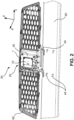
- Figures 2 illustrates an assembly 30 comprising a sensing device 10 and a fixing unit 20.
- the assembly 30 is fixed to the truck 100.
- the front grille 60 and the transverse front beam 90 have been represented, and the other mechanical elements have been omitted.
- the assembly 30 of the sensing device 10 and the fixing unit 20 is protected by a cover.
- the cover is for example formed by a bulged portion of the vehicle grille 60.
- the sensing device 10 is thus located at the front of the vehicle 100 and has a clear, non-obstructed, field of view.
- the cover offers protection from weather elements, road debris and the like.
- the cover is permeable to electromagnetic waves so that emitted waves can travel through the cover, and waves reflected by obstacles can also pass through the cover and reach the sensing device 10.
- the fixing unit 20 for fixing a sensing device 10 to an industrial vehicle 100 comprises:
- the sensing device 10 is pressed between the first bracket 1 and the second bracket 2 when the fixing lugs 3 of the second bracket 2 are locked in the first bracket 1.
- the second bracket 2 comprises a plurality of retains pins 4 that pass through the sensing device 10 and a plurality of fixing lugs 3 that are snap fitted in the first bracket 1.
- the sensing device 10 may be in direct contact with the first bracket 1 and the second bracket 2, as it is the case in the illustrated example.
- the fixing unit 20 can be fixed to the vehicle 100.
- the fixing unit 20 is an interface part between the sensing device 10 and the structure of the vehicle. The mechanical constraints associated with the fixing of the sensing device 10 to the vehicle 100 are thus supported by the fixing unit 20, and not by the sensing device 10 itself. Furthermore, the fixing unit 20 can filter out at least some of the vibrations and shocks experienced by the vehicle 100.
- the fixing unit 20 also protects the sensing device 10 during its installation on the industrial vehicle 100, since it prevents direct contact between the sensing device and environment. For example, a dropped tool is less likely to come into contact with the sensing device 10 since the two brackets 1, 2 offer protection.
- Figure 4 is an exploded view of a fixing unit 20 with a sensing device 10.
- the first bracket 1 is formed as a frame.
- the first bracket 1 has the general shape of a frame.
- the first bracket 1 is made of plastic material.
- the second bracket 2 is formed as a frame.
- the second bracket 2 is also made of plastic material. Both brackets 1, 2 have a rectangular external shape with a rectangular opening.
- the first bracket 1 comprises an opening 23 through which electromagnetic waves emitted by the sensing device can travel, and through which the electromagnetic waves reflected by the environment can reach the sensing device 10.
- the opening 23 of the first bracket 1 is approximately rectangular.
- the first bracket 1 and the second bracket 2 are stacked one over the other.
- the sensing device 10 can be inserted between the two brackets 1,2 before they are attached to each other by snap fit.
- the sensing device 10 is clamped between the two brackets 1,2 once the two brackets are fixed together by snap fit. In other words, the sensing device 10 is sandwiched between the two brackets 1, 2 when the two brackets 1, 2 are engaged one with the other.
- the plurality of retaining pins 4 is configured for passing through holes 12 of the sensing device.
- the fixing lugs 3 are of the cantilever type.
- Figure 9 illustrates the second bracket 2 in isolation from the other parts.
- the fixing lugs 3 have the general shape of a cantilever beam 24 ending by a hook 25.
- the cross section of the beam 24 is here rectangular.
- the first bracket 1 comprises engagement holes 9 in which the fixing lugs 3 can engage.
- the first bracket 1 is represented spaced apart from the second bracket 2 and the fixing lugs 3 are distant from the engagement holes 9.
- the insertion of the fixing lugs 3 of the second bracket 2 in the engagement holes 9 of the first bracket 1 generate in a first stage an elastic deflection of the beam 24 of the fixing lugs 3.
- the fixing lug 3 springs back and the recessed area 26 of the hook 25 sits flat over the surface of the first bracket 1.
- the fixing lugs 3 are locked, which secures the assembly of the first bracket 1 with the second bracket 2.
- the fixing lugs 3 are locked relatively to the first bracket 1.
- the hooks 25 are still accessible once the assembly is completed, it is possible to deflect the fixing lugs 3 to unlock them and dismantle the assembly 30.
- the retaining pins 4 are configured to pass through the sensing device 10 when the fixing lugs 3 of the second bracket 2 are engaged in the first bracket 1.
- the retaining pins 4 allow an accurate positioning of the sensing device 10 in the fixing unit 20.
- the accuracy of the sensing device 10 can be improved, since the tolerance for its location and orientation respectively to the vehicle body can be reduced.
- the sensing device 10 comprises a plurality of mounting tabs 11, each mounting tab comprising a hole 12.
- a retaining pin 4 passes through the hole 12 in each mounting tab 11.
- the mounting tabs 11 are sandwiched between the first bracket 1 and the second bracket 2 when the sensing device 10 is fixed in the fixing unit 20. This arrangement is particularly apparent on figure 8 .
- the sensing device 10 comprises three mounting tabs 11.
- the holes 12 of the three mounting tabs 11 form an isosceles triangle.
- a different number of mounting tabs is possible.
- the sensing device 10 has a general shape of rectangular cuboid, out of which the mounting tabs 11 extend. Two mounting tabs extend from a same side of the cuboid, and one mounting tab extend from the opposite side of the cuboid shape.
- a connector 14, for connection to a vehicle harness, extends from a side adjacent to both side from which the mounting tabs 11 extend.
- the top and bottom faces of the cuboid shape are roughly square, while the side faces are oblong.
- the mounting tabs 11 extend in a plane parallel to the top face of the cuboid.
- the plurality of fixing lugs 3 comprises pairs of fixings lugs, each fixing lug 3a of a pair of fixing lugs facing the other fixing lug 3b of the pair of fixing lugs.
- An arrangement with pairs of fixing lugs 3 provides a strong assembly and an easy insertion of the second bracket 2 in the first bracket 1.
- the two fixing lugs 3a, 3b of a pair of fixing lugs 3 are arranged symmetrically with respect to each other. More precisely, the two fixing lugs 3a, 3b of a pair of fixing lugs are arranged symmetrically with respect to an axis of extension A4 of a retaining pin 4, as illustrated on figure 6 .
- the axis of extension A4 of a retaining pin 4 is parallel to the direction of emission D of the radar waves.
- the axis of extension A4 of a retaining pin 4 is perpendicular to the top face of the cuboid.
- a first fixing lug 3a of a pair of fixing lugs extends along a first axis A1
- a second fixing lug 3b of the same pair of fixing lugs extends along a second axis A2
- the first axis A1 and the second axis A2 make an angle B comprised between 0° et 10°. This angle is best seen on figure 8 .
- a retaining pin 4 is disposed between the two fixing lugs 3a, 3b of a pair of fixing lugs.
- the retaining pin 4 secures the sensing device 10 on the second bracket 2 which makes the assembly process easier.
- Figure 5 represents the sensing device 10 fitted on the second bracket 2 while the first bracket 1 is not fitted yet.
- Each mounting tab 11 is fitted between the two fixing lugs 3a, 3b of a pair of fixing lugs.
- the only mechanical contact between the sensing device 10 and each bracket 1, 2 takes place through the mounting tabs 11 when the vehicle harness is not plugged in the connector 14.
- the fixing unit 20 is configured for being fixed to the industrial vehicle 100.
- the fixing unit 20 is configured for being fixed to a sub-frame 40 of the industrial vehicle 100.
- the fixing unit 20 is here bolted to a sub-frame 40 of the industrial vehicle 100.
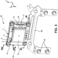
- Figure 3 illustrates an assembly 30 of a fixing unit 20, comprising a sensing device 10, on a subframe 40.
- the sub-frame 40 of the vehicle can be a metal bracket, for example a sheet metal bracket.
- the metal bracket can be assembled to a structural element 90 of the industrial vehicle. Fixing screws 45 secure the sub-frame 40 to the structural element 90.
- the first bracket 1 comprises a plurality of mounting holes 5 configured for receiving threaded fixing means 15.
- the second bracket 2 comprises a plurality of mounting holes 6 configured for receiving threaded fixing means 15.
- the mounting holes 5 of the first bracket 1 are aligned with the mounting holes 6 of the second bracket 2.
- the mounting holes 5 of the first bracket 1 are coaxial with the mounting holes 6 of the second bracket 2.
- the threaded fixing means 15 may be a set of screws configured for engaging in a subframe 40 of the vehicle.
- the threaded fixing means 15 may be a set of threaded rods engaging into a structural element of the vehicle and configured for receiving a nut.
- the first bracket 1 comprises a sleeve 7 bordering a mounting hole 5.
- each mounting hole 5 of the first bracket 1 is bordered by a sleeve 7.
- the sleeve 7 has a cylindrical shape.
- a lateral surface of the sleeve defines the lateral surface of the mounting hole.
- the internal lateral surface of the sleeve defines the lateral surface of the mounting hole.
- Each axial surface of the sleeve 7 defines an axial surface of the mounting hole 5. Each axial end of the sleeve 7 is flush with the first bracket 1.
- the second bracket 2 comprises a sleeve 8 bordering a mounting hole 6.
- Each mounting hole 6 of the second bracket 2 is here bordered by a sleeve 8.
- Figure 7 represents a cross section detailing the arrangement of the two brackets 1, 2 in the sleeves area.
- the sleeves 7 of the first bracket 1 are coaxial with the sleeves 8 of the second bracket 2.
- the dotted line indicates the common axis of the two sleeves 7,8.
- An axial end of a sleeve 7 of the first bracket 1 is in contact with an axial end of a sleeve 8 of the second bracket 2.
- the other axial end of the sleeve 7 may be in direct contact with a screw 15, or in contact via a washer spreading the force of the screw over a surface of the first bracket 1.
- the other axial end of the sleeve 8 is in contact with the subframe 40.
- the sleeves 7,8 are axially compressed when the threaded fixation means 15 are torqued.
- the sleeves 7,8 avoid putting excessive stress in the plastic part of the first bracket 1 and of the second bracket 2.
- the sleeves 7, 8 are in metal.
- the sleeves 7,8 are made of brass.
- the sleeves 7,8 may be overmolded as the first bracket 1 and the second bracket 2 are formed by plastic injection.
- the retaining pins 4 are split.
- the retaining pins 4 are configured for being elastically deformed in a radial direction when the sensing device 10 is fixed in the fixing unit 20.
- the retaining pins 4 are thus configured for generating a radial constraint against the lateral surface of the holes 12 of the mounting tabs 11 of the sensing device 10.
- the external diameter of the retaining pins 4, in a non-constrained state is larger than the internal diameter of the hole 12 of the mounting tabs 11. Therefore, the retaining pins are deformed when they are fitted in the holes 12 of the mounting tabs 4.
- some of the energy of the vibrations received by the sensing device 10 is transferred to the fixing unit 20 through the second bracket 2. Less vibration energy is transmitted to the sensing device 10, which puts less mechanical strain on the components of the sensing device 10.
- the sensing device 10 is retained to the second bracket 2 by the retaining pin 4 which prevents the parts from coming loose before the first bracket 1 is locked in the second bracket.
- Each retaining pin 4 has a general cylindrical shape with a slot 16 passing through the axis the cylinder.
- the retaining pin 4 is split according to two transverse directions.
- the retaining pin 4 has a general cylindrical shape with two slots 16, 17 passing each through the axis of the retaining pin 4, with the two slots 16, 17 extending in perpendicular planes.
- the first bracket 1 may comprise a first supporting beam 18 for a connector plugged to the sensing device 10.
- the second bracket 2 may comprise a second supporting beam 19 for the connector plugged to the sensing device 10.
- the first supporting beam 18 comprises an opening 21 configured for receiving a portion of the connector plugged to the sensing device 10.
- This connector is part of the vehicle harness.
- the sensing device 10 comprises a male connector 14 and the vehicle harness comprises a female connector.
- the sides 27,28 of the opening 21 are in contact with the connector.
- a protrusion of the vehicle harness connector fits snugly in the opening 21. The harness connector is thus held in place, and the risk of accidental unplugging of the connector is eliminated. Furthermore, the stress of the harness weight is relieved from the connector 14.
- the second bracket 2 comprises locating pins 13 configured for being inserted in a subframe 40 of the industrial vehicle 100.
- the locating pins 13 can fit in reception holes 41 of the subframe 40 of the industrial vehicle 100.
- the locating pins 13 are formed in the second bracket, therefore in the same part as the one comprising the locating pins 4. The number of elements in the stack of dimensions of the relative position of the sensing device 10 relatively to the subframe 40 is reduced, which favors the accuracy of the sensing device 10.
Landscapes
- Engineering & Computer Science (AREA)
- Radar, Positioning & Navigation (AREA)
- Remote Sensing (AREA)
- Physics & Mathematics (AREA)
- Computer Networks & Wireless Communication (AREA)
- General Physics & Mathematics (AREA)
- Electromagnetism (AREA)
- Mechanical Engineering (AREA)
- Radar Systems Or Details Thereof (AREA)
Abstract
The invention relates to a fixing unit (20) for fixing a sensing device (10) to an industrial vehicle, the fixing unit (20) comprising:
- a first bracket (1),
- a second bracket (2) comprising :
-- a plurality of fixing lugs (3) configured for snap engagement with the first bracket (1),
-- a plurality of retaining pins (4) configured for passing through the sensing device (10),
in which the sensing device (10) is pressed between the first bracket (1) and the second bracket (2) when the fixing lugs (3) of the second bracket (2) are locked in the first bracket (1).
- a first bracket (1),
- a second bracket (2) comprising :
-- a plurality of fixing lugs (3) configured for snap engagement with the first bracket (1),
-- a plurality of retaining pins (4) configured for passing through the sensing device (10),
in which the sensing device (10) is pressed between the first bracket (1) and the second bracket (2) when the fixing lugs (3) of the second bracket (2) are locked in the first bracket (1).
Description
- This disclosure relates to the field of environment sensing devices, and more particularly to a fixing unit for fixing a sensing device to an industrial vehicle.
- In order to improve vehicle safety and provide assistance to the driver, motor vehicles can be equipped with one or more sensing devices for sensing the environment of the vehicle, and detecting objects. Such a sensing device can be for example a radar, or a lidar. A radar is usually installed at the front of the vehicle and emits electromagnetic waves towards the front of the vehicle. The radar also receives the waves reflected by objects or people present in the coverage area of the radar. Signal processing of emitted waves and reflected waves enables to detect objects present in the environment of the vehicle and warning signals can be provided to the driver.
- The mechanical installation of a radar must meet different requirements. In order to guarantee a good accuracy, the space orientation of the radar relatively to the vehicle must remain constant. The radar mounting system must therefore be relatively rigid. In addition, the radar is subject to the shocks and vibrations received by the vehicle or generated by it. When the radar is installed on an industrial vehicle, such as a truck, the level of vibrations and shocks received can be much higher than when the same equipment is fitted on a road car. Consequently, a standard component developed for a passenger car environment may experience reliability issue when it is implemented on an industrial vehicle.
- There is thus a need to have a system for fixing a detection sensor that guarantees a proper operation of the detection sensor, while allowing a quick and easy installation.
- To this end, it is proposed a fixing unit for fixing a sensing device to an industrial vehicle, the fixing unit comprising:
- a first bracket,
- a second bracket comprising :
- -- a plurality of fixing lugs configured for snap engagement with the first bracket,
- -- a plurality of retaining pins configured for passing through the sensing device,
- The fixing unit can then be fixed to the vehicle. The mechanical constraints associated with the fixing on the vehicle are supported by the fixing unit, and not by the sensing device itself. Furthermore, the fixing unit can play the role of an interface part which filters out part of the vibrations and shocks experienced by the vehicle. The sensing device is thus less stressed, which is particularly beneficial when the driving conditions are rough. The fixing unit also protects the sensing device during the installation on the industrial vehicle.
- The following features can optionally be implemented, separately or in combination one with the others:
- In the meaning of the present disclosure, the sensing device is a vehicle environment sensing device.
- In an embodiment the sensing device is a radar. In a variant, the sensing device can be a lidar. In another variant, the sensing device can be a camera, for example a time-of-flight camera.
- According to an aspect of the disclosure, the plurality of retaining pins is configured for passing through holes of the sensing device.
- The first bracket and the second bracket are stacked one over the other.
- The sensing device can be inserted between the two brackets before they are attached to each other by snap fit. The sensing device is clamped between the two brackets once the two brackets are fixed together by snap fit.
- In an embodiment, the fixing lugs are of the cantilever type.
- The fixing lugs have the general shape of a cantilever beam ending by a hook.
- The cross section of the beam is for example rectangular.
- The first bracket comprises engagement holes in which the fixing lugs can engage.
- In an embodiment, the first bracket is made of plastic material.
- The first bracket is formed as a frame.
- In an embodiment, the second bracket is made of plastic material.
- In an embodiment of the fixing unit, the retaining pins are configured to pass through the sensing device when the fixing lugs of the second bracket are engaged in the first bracket.
- The retaining pins allow an accurate positioning of the sensing device in the fixing unit.
- The sensing device comprises a plurality of mounting tabs, each mounting tab comprising a hole. A retaining pin passes through the hole in each mounting tab.
- The mounting tabs are sandwiched between the first bracket and the second bracket when the sensing device is fixed in the fixing unit.
- In an embodiment of the fixing unit, the plurality of fixing lugs comprises pairs of fixings lugs, each fixing lug of a pair of fixing lugs facing the other fixing lug of the pair of fixing lugs.
- An arrangement with pairs of fixing lugs provides a strong assembly and an easy insertion of the second bracket in the first bracket.
- The two fixing lugs of a pair of fixing lugs are arranged symmetrically with respect to each other.
- According to an embodiment of the fixing unit, a retaining pin is disposed between the two fixing lugs of a pair of fixing lugs.
- The retaining pin secures the sensing device on the second bracket which makes the assembly process easier.
- In an example of implementation, the two fixing lugs of a pair of fixing lugs are arranged symmetrically with respect to an axis of extension of a retaining pin.
- A first fixing lug of a pair of fixing lugs extends along a first axis, a second fixing lug of the same pair of fixing lugs extends along a second axis, the first axis and the second axis make an angle comprised between 0° et 10°.
- According to an aspect of the disclosure, the fixing unit is configured for being fixed to the industrial vehicle.
- The fixing unit is configured for being fixed to a sub-frame of the industrial vehicle.
- For example, the fixing unit can be bolted to a sub-frame of the industrial vehicle.
- The sub-frame of the vehicle can be a metal bracket. The metal bracket can be assembled to a structural element of the industrial vehicle.
- In an embodiment of the fixing unit, the first bracket comprises a plurality of mounting holes configured for receiving threaded fixing means.
- In an embodiment of the fixing unit, the second bracket comprises a plurality of mounting holes configured for receiving threaded fixing means.
- The mounting holes of the first bracket are aligned with the mounting holes of the second bracket.
- In an example of implementation, the threaded fixing means may be a screw configured for engaging in a subframe of the vehicle.
- In another example of implementation, the threaded fixing means may be a threaded rod engaging into a structural element of the vehicle and configured for receiving a nut.
- In an embodiment, the first bracket comprises a sleeve bordering a mounting hole.
- Preferably, each mounting hole of the first bracket is bordered by a sleeve.
- In an embodiment, the second bracket comprises a sleeve bordering a mounting hole.
- Preferably, each mounting hole of the second bracket is bordered by a sleeve.
- The sleeves are in metal.
- The sleeves of the first bracket are coaxial with the sleeves of the second bracket.
- An axial end of a sleeve of the first bracket is in contact with an axial end of a sleeve of the second bracket.
- The sleeves are axially compressed when the threaded fixation means are torqued.
- The sleeves avoid putting excessive stress in the plastic part of the first and the second bracket.
- In an embodiment of the fixing unit, the retaining pins are split.
- In this embodiment, the retaining pins are configured for being elastically deformed in a radial direction when the sensing device is fixed in the fixing unit.
- The retaining pins are thus configured for generating a radial constraint against the lateral surface of the holes of the mounting tabs of the sensing device. Therefore, some of the energy of the vibrations received by the sensing device is transferred to the fixing unit through the second bracket.
- In a particular embodiment, the retaining pin is split according to two transverse directions.
- The first bracket may comprise a first supporting beam for a connector plugged to the sensing device.
- Similarly, the second bracket may comprise a second supporting beam for the connector plugged to the sensing device.
- In an embodiment, the first supporting beam comprises an opening configured for receiving a portion of the connector plugged to the sensing device.
- The connector is thus held in place, and the risk of accidental unplugging of the connector is eliminated.
- The sides of the opening are in contact with the connector.
- In an embodiment, the second bracket comprises locating pins configured for being inserted in a subframe of the industrial vehicle.
- The disclosure also relates to an assembly comprising a sensing device and a fixing unit as described before.
- The disclosure refers as well to an industrial vehicle comprising a fixing unit as already described, or comprising an assembly as mentioned above, in which a sensing device is fixed to a front part of the industrial vehicle by the fixing unit and in which the sensing device senses the environment of the industrial vehicle.
- The industrial vehicle is a truck, for example a porter truck or a long-haul truck.
- The front part is a transverse front beam of the industrial vehicle.
- An emission direction of the sensing device coincides with a longitudinal axis of the industrial vehicle.
- The assembly of the sensing device and the fixing unit is protected by a cover.
- The cover is for example formed by a bulged portion of a vehicle grille.
- Other features, details and advantages will be shown in the following detailed description and on the figures, on which:
-
Figure 1 is a side view of an industrial vehicle equipped with a fixing unit according to an embodiment of the invention, -
Figure 2 is a perspective view of an assembly comprising the fixing unit offigure 1 , -
Figure 3 is another perspective view of the assembly offigure 2 , -
Figure 4 is an exploded view of the fixing unit offigure 2 and3 , -
Figure 5 is a perspective view of a part of the fixing unit offigure 4 , -
Figure 6 is another exploded view of the fixing unit offigure 4 , -
Figure 7 is a sectioned view of the fixing unit offigure 5 , -
Figure 8 is another sectioned view of the fixing unit offigure 5 , -
Figure 9 is a detailed view of a bracket comprised in the fixing unit. - In order to make the figures easier to read, the various elements are not necessarily represented to scale. In these figures, identical elements receive the same reference number. Certain elements or parameters can be indexed, that is to say designated for example by 'first element' or second element, or first parameter and second parameter, etc. The purpose of this indexing is to differentiate elements or parameters that are similar, but not identical. This indexing does not imply a priority of one element, or one parameter over another, and their names can be interchanged. When it is mentioned that a subsystem comprises a given element, the presence of other elements in this subsystem is not excluded.
-
Figure 1 illustrates anindustrial vehicle 100. Theindustrial vehicle 100 is a truck, more precisely a long-haul truck. It could also be a porter truck. The present disclosure can also be applied to other types of industrial vehicles, such as a construction truck, or a bus. - The
industrial vehicle 100 comprises asensing device 10. Thesensing device 10 is fixed to a front part of theindustrial vehicle 100 by a fixingunit 20 that will be described in detail below. Thesensing device 10 senses the environment of theindustrial vehicle 100. The front part, as represented onfigure 2 , is in the illustrated example a transversefront beam 90 of theindustrial vehicle 100. - In the meaning of the present disclosure, the
sensing device 10 is a vehicle environment sensing device. Thesensing device 10 is configured for sensing the environment of thevehicle 100 in order to detect objects located in a field of view of thesensing device 10. A driver assistance system processes the data captured by thesensing device 10 and can indicate the position of the detected obstacles. Warning signals can be generated so that the driver reacts accordingly. - In the illustrated embodiment, the
sensing device 10 is a radar. An emission direction D of thesensing device 10 coincides onfigure 1 with a longitudinal axis X of theindustrial vehicle 100. - In a variant, the
sensing device 10 can be a lidar. In another variant, thesensing device 10 can be a camera, for example a time-of-flight camera. (ToF) - The
industrial vehicle 100 comprises anassembly 30 of asensing device 10 and a fixingunit 20. - The fixing
unit 20 that will be described in detail below. -
Figures 2 illustrates anassembly 30 comprising asensing device 10 and a fixingunit 20. Theassembly 30 is fixed to thetruck 100. For clarity, only thefront grille 60 and thetransverse front beam 90 have been represented, and the other mechanical elements have been omitted. - The
assembly 30 of thesensing device 10 and the fixingunit 20 is protected by a cover. The cover is for example formed by a bulged portion of thevehicle grille 60. Thesensing device 10 is thus located at the front of thevehicle 100 and has a clear, non-obstructed, field of view. The cover offers protection from weather elements, road debris and the like. The cover is permeable to electromagnetic waves so that emitted waves can travel through the cover, and waves reflected by obstacles can also pass through the cover and reach thesensing device 10. - The fixing
unit 20 for fixing asensing device 10 to anindustrial vehicle 100 comprises: - a
first bracket 1, - a
second bracket 2 comprising :- -- a plurality of fixing
lugs 3 configured for snap engagement with thefirst bracket 1, - -- a plurality of retaining
pins 4 configured for passing through thesensing device 10.
- -- a plurality of fixing
- The
sensing device 10 is pressed between thefirst bracket 1 and thesecond bracket 2 when the fixing lugs 3 of thesecond bracket 2 are locked in thefirst bracket 1. - In other words, the
second bracket 2 comprises a plurality of retainspins 4 that pass through thesensing device 10 and a plurality of fixinglugs 3 that are snap fitted in thefirst bracket 1. Thesensing device 10 may be in direct contact with thefirst bracket 1 and thesecond bracket 2, as it is the case in the illustrated example. - The fixing
unit 20 can be fixed to thevehicle 100. The fixingunit 20 is an interface part between thesensing device 10 and the structure of the vehicle. The mechanical constraints associated with the fixing of thesensing device 10 to thevehicle 100 are thus supported by the fixingunit 20, and not by thesensing device 10 itself. Furthermore, the fixingunit 20 can filter out at least some of the vibrations and shocks experienced by thevehicle 100. The fixingunit 20 also protects thesensing device 10 during its installation on theindustrial vehicle 100, since it prevents direct contact between the sensing device and environment. For example, a dropped tool is less likely to come into contact with thesensing device 10 since the twobrackets -
Figure 4 is an exploded view of a fixingunit 20 with asensing device 10. - The
first bracket 1 is formed as a frame. Thefirst bracket 1 has the general shape of a frame. Thefirst bracket 1 is made of plastic material. Similarly, thesecond bracket 2 is formed as a frame. Thesecond bracket 2 is also made of plastic material. Bothbrackets - The
first bracket 1 comprises anopening 23 through which electromagnetic waves emitted by the sensing device can travel, and through which the electromagnetic waves reflected by the environment can reach thesensing device 10. Theopening 23 of thefirst bracket 1 is approximately rectangular. - The
first bracket 1 and thesecond bracket 2 are stacked one over the other. Thesensing device 10 can be inserted between the twobrackets sensing device 10 is clamped between the twobrackets sensing device 10 is sandwiched between the twobrackets brackets pins 4 is configured for passing throughholes 12 of the sensing device. - On the example illustrated on
figures 3 to 9 , the fixing lugs 3 are of the cantilever type.Figure 9 illustrates thesecond bracket 2 in isolation from the other parts. As detailed on this figure; the fixing lugs 3 have the general shape of acantilever beam 24 ending by ahook 25. The cross section of thebeam 24 is here rectangular. - As detailed on
figure 6 , thefirst bracket 1 comprisesengagement holes 9 in which the fixing lugs 3 can engage. On this figure, thefirst bracket 1 is represented spaced apart from thesecond bracket 2 and the fixing lugs 3 are distant from the engagement holes 9. The insertion of the fixing lugs 3 of thesecond bracket 2 in the engagement holes 9 of thefirst bracket 1 generate in a first stage an elastic deflection of thebeam 24 of the fixing lugs 3. Once the recessedarea 26 of thehook 25 has been pushed far enough to exit theengagement hole 9, the fixinglug 3 springs back and the recessedarea 26 of thehook 25 sits flat over the surface of thefirst bracket 1. At this stage, the fixing lugs 3 are locked, which secures the assembly of thefirst bracket 1 with thesecond bracket 2. Onfigure 7 andfigure 8 , the fixing lugs 3 are locked relatively to thefirst bracket 1. As thehooks 25 are still accessible once the assembly is completed, it is possible to deflect the fixing lugs 3 to unlock them and dismantle theassembly 30. - As detailed on
figure 8 , the retaining pins 4 are configured to pass through thesensing device 10 when the fixing lugs 3 of thesecond bracket 2 are engaged in thefirst bracket 1. The retaining pins 4 allow an accurate positioning of thesensing device 10 in the fixingunit 20. The accuracy of thesensing device 10 can be improved, since the tolerance for its location and orientation respectively to the vehicle body can be reduced. - The
sensing device 10 comprises a plurality of mountingtabs 11, each mounting tab comprising ahole 12. A retainingpin 4 passes through thehole 12 in each mountingtab 11. - The mounting
tabs 11 are sandwiched between thefirst bracket 1 and thesecond bracket 2 when thesensing device 10 is fixed in the fixingunit 20. This arrangement is particularly apparent onfigure 8 . - In the illustrated example, the
sensing device 10 comprises three mountingtabs 11. Theholes 12 of the three mountingtabs 11 form an isosceles triangle. A different number of mounting tabs is possible. Thesensing device 10 has a general shape of rectangular cuboid, out of which the mountingtabs 11 extend. Two mounting tabs extend from a same side of the cuboid, and one mounting tab extend from the opposite side of the cuboid shape. Aconnector 14, for connection to a vehicle harness, extends from a side adjacent to both side from which the mountingtabs 11 extend. The top and bottom faces of the cuboid shape are roughly square, while the side faces are oblong. The mountingtabs 11 extend in a plane parallel to the top face of the cuboid. - The plurality of fixing
lugs 3 comprises pairs of fixings lugs, each fixinglug 3a of a pair of fixing lugs facing the other fixinglug 3b of the pair of fixing lugs. An arrangement with pairs of fixinglugs 3 provides a strong assembly and an easy insertion of thesecond bracket 2 in thefirst bracket 1. - As detailed on
figure 8 , the two fixinglugs lugs 3 are arranged symmetrically with respect to each other. More precisely, the two fixinglugs pin 4, as illustrated onfigure 6 . The axis of extension A4 of a retainingpin 4 is parallel to the direction of emission D of the radar waves. The axis of extension A4 of a retainingpin 4 is perpendicular to the top face of the cuboid. - A first fixing
lug 3a of a pair of fixing lugs extends along a first axis A1, asecond fixing lug 3b of the same pair of fixing lugs extends along a second axis A2, the first axis A1 and the second axis A2 make an angle B comprised between 0° et 10°. This angle is best seen onfigure 8 . - A retaining
pin 4 is disposed between the two fixinglugs pin 4 secures thesensing device 10 on thesecond bracket 2 which makes the assembly process easier.Figure 5 represents thesensing device 10 fitted on thesecond bracket 2 while thefirst bracket 1 is not fitted yet. Each mountingtab 11 is fitted between the two fixinglugs - On the illustrated example, the only mechanical contact between the
sensing device 10 and eachbracket tabs 11 when the vehicle harness is not plugged in theconnector 14. In particular, there is a gap between the internal edges of the brackets and the sides from which the mountingtabs 11 extend. - As already described, the fixing
unit 20 is configured for being fixed to theindustrial vehicle 100. In this illustrated example, the fixingunit 20 is configured for being fixed to asub-frame 40 of theindustrial vehicle 100. The fixingunit 20 is here bolted to asub-frame 40 of theindustrial vehicle 100.Figure 3 illustrates anassembly 30 of a fixingunit 20, comprising asensing device 10, on asubframe 40. - The
sub-frame 40 of the vehicle can be a metal bracket, for example a sheet metal bracket. The metal bracket can be assembled to astructural element 90 of the industrial vehicle. Fixing screws 45 secure thesub-frame 40 to thestructural element 90. - The
first bracket 1 comprises a plurality of mountingholes 5 configured for receiving threaded fixing means 15. Similarly, thesecond bracket 2 comprises a plurality of mountingholes 6 configured for receiving threaded fixing means 15. - The mounting
holes 5 of thefirst bracket 1 are aligned with the mountingholes 6 of thesecond bracket 2. The mountingholes 5 of thefirst bracket 1 are coaxial with the mountingholes 6 of thesecond bracket 2. - As represented on
figure 3 andfigure 4 , the threaded fixing means 15 may be a set of screws configured for engaging in asubframe 40 of the vehicle. - In another example of implementation, non-represented, the threaded fixing means 15 may be a set of threaded rods engaging into a structural element of the vehicle and configured for receiving a nut.
- The
first bracket 1 comprises asleeve 7 bordering a mountinghole 5. Preferably, each mountinghole 5 of thefirst bracket 1 is bordered by asleeve 7. Thesleeve 7 has a cylindrical shape. - A lateral surface of the sleeve defines the lateral surface of the mounting hole. The internal lateral surface of the sleeve defines the lateral surface of the mounting hole.
- Each axial surface of the
sleeve 7 defines an axial surface of the mountinghole 5. Each axial end of thesleeve 7 is flush with thefirst bracket 1. - In an analogous way, the
second bracket 2 comprises asleeve 8 bordering a mountinghole 6. Each mountinghole 6 of thesecond bracket 2 is here bordered by asleeve 8. -
Figure 7 represents a cross section detailing the arrangement of the twobrackets sleeves 7 of thefirst bracket 1 are coaxial with thesleeves 8 of thesecond bracket 2. The dotted line indicates the common axis of the twosleeves sleeve 7 of thefirst bracket 1 is in contact with an axial end of asleeve 8 of thesecond bracket 2. The other axial end of thesleeve 7 may be in direct contact with ascrew 15, or in contact via a washer spreading the force of the screw over a surface of thefirst bracket 1. The other axial end of thesleeve 8 is in contact with thesubframe 40. - The
sleeves sleeves first bracket 1 and of thesecond bracket 2. - The
sleeves sleeves - The
sleeves first bracket 1 and thesecond bracket 2 are formed by plastic injection. - In the embodiment illustrated here, the retaining pins 4 are split. The retaining pins 4 are configured for being elastically deformed in a radial direction when the
sensing device 10 is fixed in the fixingunit 20. - The retaining pins 4 are thus configured for generating a radial constraint against the lateral surface of the
holes 12 of the mountingtabs 11 of thesensing device 10. In other words, the external diameter of the retaining pins 4, in a non-constrained state, is larger than the internal diameter of thehole 12 of the mountingtabs 11. Therefore, the retaining pins are deformed when they are fitted in theholes 12 of the mountingtabs 4. As a result, some of the energy of the vibrations received by thesensing device 10 is transferred to the fixingunit 20 through thesecond bracket 2. Less vibration energy is transmitted to thesensing device 10, which puts less mechanical strain on the components of thesensing device 10. Furthermore, thesensing device 10 is retained to thesecond bracket 2 by the retainingpin 4 which prevents the parts from coming loose before thefirst bracket 1 is locked in the second bracket. - Each retaining
pin 4 has a general cylindrical shape with aslot 16 passing through the axis the cylinder. In the illustrated example, as detailed onfigure 9 , the retainingpin 4 is split according to two transverse directions. In other words, the retainingpin 4 has a general cylindrical shape with twoslots pin 4, with the twoslots - The
first bracket 1 may comprise a first supportingbeam 18 for a connector plugged to thesensing device 10. Similarly, thesecond bracket 2 may comprise a second supportingbeam 19 for the connector plugged to thesensing device 10. - The first supporting
beam 18 comprises anopening 21 configured for receiving a portion of the connector plugged to thesensing device 10. This connector, not represented on the figures, is part of the vehicle harness. On the illustrated example, thesensing device 10 comprises amale connector 14 and the vehicle harness comprises a female connector. Thesides opening 21 are in contact with the connector. A protrusion of the vehicle harness connector fits snugly in theopening 21. The harness connector is thus held in place, and the risk of accidental unplugging of the connector is eliminated. Furthermore, the stress of the harness weight is relieved from theconnector 14. - The
second bracket 2 comprises locatingpins 13 configured for being inserted in asubframe 40 of theindustrial vehicle 100. The locating pins 13 can fit in reception holes 41 of thesubframe 40 of theindustrial vehicle 100. The locating pins 13 are formed in the second bracket, therefore in the same part as the one comprising the locating pins 4. The number of elements in the stack of dimensions of the relative position of thesensing device 10 relatively to thesubframe 40 is reduced, which favors the accuracy of thesensing device 10.
Claims (15)
- A fixing unit (20) for fixing a sensing device (10) to an industrial vehicle (100), the fixing unit (20) comprising:- a first bracket (1),- a second bracket (2) comprising :-- a plurality of fixing lugs (3) configured for snap engagement with the first bracket (1),-- a plurality of retaining pins (4) configured for passing through the sensing device (10), in which the sensing device (10) is pressed between the first bracket (1) and the second bracket (2) when the fixing lugs (3) of the second bracket (2) are locked in the first bracket (1).
- A fixing unit (20) according to claim 1, in which the sensing device (10) is a radar, or a lidar, or a camera, for example a time-of-flight camera.
- A fixing unit (20) according to claim 1 or 2, in which the retaining pins (4) are configured to pass through the sensing device (10) when the fixing lugs (3) of the second bracket (2) are engaged in the first bracket (1).
- A fixing unit (20) according to any one of the preceding claims, in which the plurality of fixing lugs (3) comprises pairs of fixings lugs, each fixing lug (3a) of a pair of fixing lugs facing the other fixing lug (3b) of the pair of fixing lugs.
- A fixing unit (20) according to the preceding claim, in which a retaining pin (4) is disposed between the two fixing lugs (3a, 3b) of a pair of fixing lugs.
- A fixing unit (20) according to claim 4 or 5, in which the two fixing lugs (3a, 3b) of a pair of fixing lugs are arranged symmetrically with respect to an axis of extension (A4) of a retaining pin (4).
- A fixing unit (20) according to any one of the preceding claims, in which the first bracket (1) comprises a plurality of mounting holes (5) configured for receiving threaded fixing means (15),in which the second bracket (2) comprises a plurality of mounting holes (6) configured for receiving threaded fixing means (15),and in which the mounting holes (5) of the first bracket (1) are aligned with the mounting holes (6) of the second bracket (2).
- A fixing unit (20) according to the preceding claim, in which each mounting hole (5) of the first bracket (1) is bordered by a metal sleeve (7),
and in which each mounting hole (6) of the second bracket (2) is bordered by a metal sleeve (8). - A fixing unit (20) according to any one of the preceding claims, in which the retaining pins (4) are split,
and in which the retaining pins (4) are configured for being elastically deformed in a radial direction when the sensing device (10) is fixed in the fixing unit (20). - A fixing unit (20) according to any one of the preceding claims, in which the first bracket (1) comprises a first supporting beam (18) for a connector plugged to the sensing device (10)
and in which the second bracket (2) comprises a second supporting beam (19) for the connector plugged to the sensing device (10). - A fixing unit (20) according to the preceding claim, in which the first supporting beam (18) comprises an opening (21) configured for receiving a portion of the connector plugged to the sensing device (10).
- A fixing unit (20) according to any one of the preceding claims, in which the second bracket (2) comprises locating pins (13) configured for being inserted in a subframe (40) of the industrial vehicle (100).
- An assembly (30) comprising a sensing device (10) and a fixing unit (20) according to one of preceding claims.
- An industrial vehicle (100) comprising a fixing unit (20) according to any of claims 1 to 12, or comprising an assembly (30) according to claim 13, in which a sensing device (10) is fixed to a front part of the industrial vehicle (100) by the fixing unit (20) and in which the sensing device (10) senses the environment of the industrial vehicle (100).
- An industrial vehicle (100) according to the preceding claim, in which the industrial vehicle is a long-haul truck or a porter truck.
Priority Applications (2)
| Application Number | Priority Date | Filing Date | Title |
|---|---|---|---|
| EP23171238.1A EP4458618A1 (en) | 2023-05-03 | 2023-05-03 | Sensing device fixing unit for an industrial vehicle |
| US18/636,474 US20240369699A1 (en) | 2023-05-03 | 2024-04-16 | Sensing device fixing unit for an industrial vehicle |
Applications Claiming Priority (1)
| Application Number | Priority Date | Filing Date | Title |
|---|---|---|---|
| EP23171238.1A EP4458618A1 (en) | 2023-05-03 | 2023-05-03 | Sensing device fixing unit for an industrial vehicle |
Publications (1)
| Publication Number | Publication Date |
|---|---|
| EP4458618A1 true EP4458618A1 (en) | 2024-11-06 |
Family
ID=86329536
Family Applications (1)
| Application Number | Title | Priority Date | Filing Date |
|---|---|---|---|
| EP23171238.1A Pending EP4458618A1 (en) | 2023-05-03 | 2023-05-03 | Sensing device fixing unit for an industrial vehicle |
Country Status (2)
| Country | Link |
|---|---|
| US (1) | US20240369699A1 (en) |
| EP (1) | EP4458618A1 (en) |
Citations (3)
| Publication number | Priority date | Publication date | Assignee | Title |
|---|---|---|---|---|
| US20040239574A1 (en) * | 2001-11-02 | 2004-12-02 | Juergen Zeiher | Positioning device for adjustable housing |
| KR20200044301A (en) * | 2018-10-19 | 2020-04-29 | 주식회사 만도 | Radar System Mounting Assembly and Radar Sensing System Having the Same |
| US20200361398A1 (en) * | 2019-05-13 | 2020-11-19 | Honda Motor Co., Ltd. | External sensor attachment portion structure |
-
2023
- 2023-05-03 EP EP23171238.1A patent/EP4458618A1/en active Pending
-
2024
- 2024-04-16 US US18/636,474 patent/US20240369699A1/en active Pending
Patent Citations (3)
| Publication number | Priority date | Publication date | Assignee | Title |
|---|---|---|---|---|
| US20040239574A1 (en) * | 2001-11-02 | 2004-12-02 | Juergen Zeiher | Positioning device for adjustable housing |
| KR20200044301A (en) * | 2018-10-19 | 2020-04-29 | 주식회사 만도 | Radar System Mounting Assembly and Radar Sensing System Having the Same |
| US20200361398A1 (en) * | 2019-05-13 | 2020-11-19 | Honda Motor Co., Ltd. | External sensor attachment portion structure |
Also Published As
| Publication number | Publication date |
|---|---|
| US20240369699A1 (en) | 2024-11-07 |
Similar Documents
| Publication | Publication Date | Title |
|---|---|---|
| CN111267740B (en) | Detection device and vehicle | |
| US8414013B2 (en) | Housing structure for in-vehicle electronic device | |
| US11203313B2 (en) | Sensor attachment structure and moving body | |
| JP5184286B2 (en) | Housing fixing structure | |
| US11809072B2 (en) | Vehicle camera holding device | |
| US11914032B2 (en) | Radar support device | |
| US7277022B2 (en) | Sensor device and method for arranging a sensor device on a mounting plate | |
| WO2016098486A1 (en) | Vehicle radar device | |
| US9358864B2 (en) | Device for fastening a battery module to a bodyshell of a motor vehicle | |
| CN114600442B (en) | Camera modules for vehicles | |
| US20240369699A1 (en) | Sensing device fixing unit for an industrial vehicle | |
| US11201421B2 (en) | Printed circuit board mounting arrangement | |
| US20200011969A1 (en) | Axial misalignment determination method of object detection sensor | |
| WO2000047451A1 (en) | Air bag sensor module installation apparatus and method | |
| CN214523599U (en) | Sensor Mounting Bracket | |
| EP1878624B1 (en) | Device for detecting objects near vehicles | |
| US6264232B1 (en) | Air bag sensor module installation apparatus and method | |
| JP4793221B2 (en) | Electronic component mounting structure and electronic component mounting method | |
| US11852286B2 (en) | Sensor bracket structure | |
| CN217170620U (en) | Vehicle-mounted radar arrangement and installation structure and automobile | |
| KR101821840B1 (en) | Radar test apparatus | |
| JP7608140B2 (en) | Structure | |
| KR20170034487A (en) | Radar Apparatus | |
| CN216930599U (en) | Electronic device | |
| CN111267742B (en) | Detection device and vehicle |
Legal Events
| Date | Code | Title | Description |
|---|---|---|---|
| PUAI | Public reference made under article 153(3) epc to a published international application that has entered the european phase |
Free format text: ORIGINAL CODE: 0009012 |
|
| STAA | Information on the status of an ep patent application or granted ep patent |
Free format text: STATUS: THE APPLICATION HAS BEEN PUBLISHED |
|
| AK | Designated contracting states |
Kind code of ref document: A1 Designated state(s): AL AT BE BG CH CY CZ DE DK EE ES FI FR GB GR HR HU IE IS IT LI LT LU LV MC ME MK MT NL NO PL PT RO RS SE SI SK SM TR |
|
| STAA | Information on the status of an ep patent application or granted ep patent |
Free format text: STATUS: REQUEST FOR EXAMINATION WAS MADE |
|
| 17P | Request for examination filed |
Effective date: 20250408 |