EP4458614A1 - Vehicle detection device, light distribution control device, and vehicle detection method - Google Patents
Vehicle detection device, light distribution control device, and vehicle detection method Download PDFInfo
- Publication number
- EP4458614A1 EP4458614A1 EP22915658.3A EP22915658A EP4458614A1 EP 4458614 A1 EP4458614 A1 EP 4458614A1 EP 22915658 A EP22915658 A EP 22915658A EP 4458614 A1 EP4458614 A1 EP 4458614A1
- Authority
- EP
- European Patent Office
- Prior art keywords
- vehicle
- angle
- region
- light distribution
- tilt
- Prior art date
- Legal status (The legal status is an assumption and is not a legal conclusion. Google has not performed a legal analysis and makes no representation as to the accuracy of the status listed.)
- Withdrawn
Links
Images


Classifications
-
- B—PERFORMING OPERATIONS; TRANSPORTING
- B62—LAND VEHICLES FOR TRAVELLING OTHERWISE THAN ON RAILS
- B62J—CYCLE SADDLES OR SEATS; AUXILIARY DEVICES OR ACCESSORIES SPECIALLY ADAPTED TO CYCLES AND NOT OTHERWISE PROVIDED FOR, e.g. ARTICLE CARRIERS OR CYCLE PROTECTORS
- B62J6/00—Arrangement of optical signalling or lighting devices on cycles; Mounting or supporting thereof; Circuits therefor
- B62J6/02—Headlights
- B62J6/022—Headlights specially adapted for motorcycles or the like
- B62J6/023—Headlights specially adapted for motorcycles or the like responsive to the lean angle of the cycle, e.g. changing intensity or switching sub-lights when cornering
-
- B—PERFORMING OPERATIONS; TRANSPORTING
- B60—VEHICLES IN GENERAL
- B60Q—ARRANGEMENT OF SIGNALLING OR LIGHTING DEVICES, THE MOUNTING OR SUPPORTING THEREOF OR CIRCUITS THEREFOR, FOR VEHICLES IN GENERAL
- B60Q1/00—Arrangement of optical signalling or lighting devices, the mounting or supporting thereof or circuits therefor
- B60Q1/02—Arrangement of optical signalling or lighting devices, the mounting or supporting thereof or circuits therefor the devices being primarily intended to illuminate the way ahead or to illuminate other areas of way or environments
- B60Q1/04—Arrangement of optical signalling or lighting devices, the mounting or supporting thereof or circuits therefor the devices being primarily intended to illuminate the way ahead or to illuminate other areas of way or environments the devices being headlights
- B60Q1/14—Arrangement of optical signalling or lighting devices, the mounting or supporting thereof or circuits therefor the devices being primarily intended to illuminate the way ahead or to illuminate other areas of way or environments the devices being headlights having dimming means
-
- G—PHYSICS
- G06—COMPUTING OR CALCULATING; COUNTING
- G06V—IMAGE OR VIDEO RECOGNITION OR UNDERSTANDING
- G06V10/00—Arrangements for image or video recognition or understanding
- G06V10/10—Image acquisition
- G06V10/12—Details of acquisition arrangements; Constructional details thereof
- G06V10/14—Optical characteristics of the device performing the acquisition or on the illumination arrangements
- G06V10/141—Control of illumination
-
- G—PHYSICS
- G06—COMPUTING OR CALCULATING; COUNTING
- G06V—IMAGE OR VIDEO RECOGNITION OR UNDERSTANDING
- G06V10/00—Arrangements for image or video recognition or understanding
- G06V10/20—Image preprocessing
- G06V10/24—Aligning, centring, orientation detection or correction of the image
- G06V10/242—Aligning, centring, orientation detection or correction of the image by image rotation, e.g. by 90 degrees
-
- G—PHYSICS
- G06—COMPUTING OR CALCULATING; COUNTING
- G06V—IMAGE OR VIDEO RECOGNITION OR UNDERSTANDING
- G06V20/00—Scenes; Scene-specific elements
- G06V20/50—Context or environment of the image
- G06V20/56—Context or environment of the image exterior to a vehicle by using sensors mounted on the vehicle
- G06V20/58—Recognition of moving objects or obstacles, e.g. vehicles or pedestrians; Recognition of traffic objects, e.g. traffic signs, traffic lights or roads
- G06V20/584—Recognition of moving objects or obstacles, e.g. vehicles or pedestrians; Recognition of traffic objects, e.g. traffic signs, traffic lights or roads of vehicle lights or traffic lights
-
- G—PHYSICS
- G06—COMPUTING OR CALCULATING; COUNTING
- G06V—IMAGE OR VIDEO RECOGNITION OR UNDERSTANDING
- G06V20/00—Scenes; Scene-specific elements
- G06V20/60—Type of objects
-
- H—ELECTRICITY
- H04—ELECTRIC COMMUNICATION TECHNIQUE
- H04N—PICTORIAL COMMUNICATION, e.g. TELEVISION
- H04N23/00—Cameras or camera modules comprising electronic image sensors; Control thereof
- H04N23/60—Control of cameras or camera modules
- H04N23/695—Control of camera direction for changing a field of view, e.g. pan, tilt or based on tracking of objects
-
- G—PHYSICS
- G06—COMPUTING OR CALCULATING; COUNTING
- G06V—IMAGE OR VIDEO RECOGNITION OR UNDERSTANDING
- G06V2201/00—Indexing scheme relating to image or video recognition or understanding
- G06V2201/08—Detecting or categorising vehicles
Definitions
- the present invention relates to vehicle detecting devices, light distribution controlling devices, and vehicle detecting methods.
- Adaptive driving beam (ADB) control is proposed that dynamically and adaptively controls light distribution patterns based on the circumstances surrounding the vehicle.
- ADB control detects, with a camera, the presence of a front vehicle that should not be illuminated with high-illuminance light and blocks the region of light that corresponds to the front vehicle (see, for example, Patent Literature 1). Blocking the region of light that corresponds to the front vehicle can reduce glare caused on the driver of the front vehicle and can also improve the visibility of the driver of the host vehicle.
- Patent Literature 1 JP 2015-064964
- front vehicles should desirably be detected with high accuracy.
- the present inventors have conducted diligent investigations into the techniques for detecting front vehicles and found that the accuracy of detecting front vehicles can decrease when the host vehicle become tilted.
- the present invention has been made in the light of such circumstances and is, in one aspect, directed to providing a technique for increasing the accuracy of detecting a front vehicle.
- one aspect of the present invention provides a vehicle detecting device.
- This vehicle detecting device performs a process of detecting a front vehicle using an image that is based on an imaging device provided in a vehicle, and in accordance with a change in an angle of tilt of the vehicle's right-left axis, modifies an imaging region of the imaging device so as to mitigate a shift in the imaging region caused by the change.
- Another aspect of the present invention provides a light distribution controlling device.
- This light distribution controlling device based on a detection result of the vehicle detecting device of the aspect above, sets a light distribution pattern that includes a shaded region to overlap the front vehicle.
- Yet another aspect of the present invention provides a vehicle detecting method.
- This vehicle detecting method includes performing a process of detecting a front vehicle using an image that is based on an imaging device provided in a vehicle, and in accordance with a change in an angle of tilt of the vehicle's right-left axis, modifying an imaging region of the imaging device so as to mitigate a shift in the imaging region caused by the change.
- one aspect of the present invention provides a vehicle detecting device.
- This vehicle detecting device sets a processing region in an image that is based on an imaging device provided in a vehicle, performs a process of detecting a front vehicle from the processing region, and in accordance with a change in an angle of tilt of the vehicle's right-left axis, modifies the processing region so as to mitigate a shift in the processing region caused by the change.
- Another aspect of the present invention provides a light distribution controlling device.
- This light distribution controlling device based on a detection result of the vehicle detecting device of the aspect above, sets a light distribution pattern that includes a shaded region to overlap the front vehicle.
- Yet another aspect of the present invention provides a vehicle detecting method.
- This vehicle detecting method includes setting a processing region in an image that is based on an imaging device provided in a vehicle, performing a process of detecting a front vehicle from the processing region, and in accordance with a change in an angle of tilt of the vehicle's right-left axis, modifying the processing region so as to mitigate a shift in the processing region caused by the change.
- one aspect of the present invention provides a vehicle detecting device.
- This vehicle detecting device using a structuring element of a predetermined shape, performs a dilation process on a luminous point included in an image that is based on an imaging device provided in a vehicle; when there is another dilated luminous point to be coupled to the dilated luminous point, detects a front vehicle based on the two luminous points; and in accordance with a change in an angle of tilt of the vehicle's right-left axis, modifies the structuring element so as to absorb an offset between the luminous points in the image caused by the change.
- Another aspect of the present invention provides a light distribution controlling device.
- This light distribution controlling device based on a detection result of the vehicle detecting device of the aspect above, sets a light distribution pattern that includes a shaded region to overlap the front vehicle.
- Yet another aspect of the present invention provides a vehicle detecting method.
- This vehicle detecting method includes, by using a structuring element of a predetermined shape, performing a dilation process on a luminous point included in an image that is based on an imaging device provided in a vehicle; when there is another dilated luminous point to be coupled to the dilated luminous point, detecting a front vehicle based on the two luminous points; and in accordance with a change in an angle of tilt of the vehicle's right-left axis, modifying the structuring element so as to absorb an offset between the luminous points in the image caused by the change.
- one aspect of the present invention provides a vehicle detecting device.
- This vehicle detecting device when two luminous points included in an image that is based on an imaging device provided in a vehicle satisfy a predetermined pair determining condition, detects a front vehicle based on the two luminous points, and in accordance with a change in an angle of tilt of the vehicle's right-left axis, relaxes the pair determining condition so as to absorb an offset between the luminous points in the image caused by the change.
- Another aspect of the present invention provides a light distribution controlling device.
- This light distribution controlling device based on a detection result of the vehicle detecting device of the aspect above, sets a light distribution pattern that includes a shaded region to overlap the front vehicle.
- Yet another aspect of the present invention provides a vehicle detecting method.
- This vehicle detecting method includes, when two luminous points included in an image that is based on an imaging device provided in a vehicle satisfy a predetermined pair determining condition, detecting a front vehicle based on the two luminous points, and in accordance with a change in an angle of tilt of the vehicle's right-left axis, relaxing the pair determining condition so as to absorb an offset between the luminous points in the image caused by the change.
- the present invention can increase the accuracy of detecting a front vehicle.
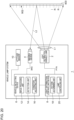
- Fig. 1 is a block diagram of a vehicle lamp system 1.
- Fig. 1 depicts constituent elements of the vehicle lamp system 1 in the form of functional blocks. These functional blocks are implemented, as to their hardware configuration, by elements or circuits, such as a CPU or memory of a computer, or implemented, as to their software configuration, by a computer program or the like. It is to be appreciated by a person skilled in the art that these functional blocks can be implemented in a variety of forms through combinations of hardware and software.
- the vehicle lamp system 1 includes a light distribution variable lamp 2, an imaging device 4, a vehicle detecting device 6, a light distribution controlling device 8, and an attitude sensor 10. These components are provided in a vehicle.
- a vehicle in which the vehicle lamp system 1 is provided according to the present embodiment is a straddle-type vehicle, such as a motorcycle.
- the light distribution variable lamp 2, the imaging device 4, the vehicle detecting device 6, the light distribution controlling device 8, and the attitude sensor 10 may all be contained within a single housing, or some of these members may be provided outside such a housing.
- the light distribution variable lamp 2, the imaging device 4, the vehicle detecting device 6, the light distribution controlling device 8, and the attitude sensor 10 are housed in a lamp room.
- the lamp room is defined by a lamp body having an opening that opens to the front side of the vehicle and a light-transmissive cover attached so as to cover the opening of the lamp body.
- the imaging device 4, the vehicle detecting device 6, the light distribution controlling device 8, and the attitude sensor 10 may be provided outside the lamp room, such as in the vehicle. In this case, the imaging device 4 may be an onboard camera.
- the vehicle detecting device 6 and the light distribution controlling device 8 may be, for example, entirely or partly constituted by a vehicle ECU. An imaging adjusting unit 30 and so forth, described later, of the vehicle detecting device 6 may be embedded in the imaging device 4.
- the light distribution variable lamp 2 is capable of illuminating a region ahead of the host vehicle with a visible light beam L1 of a variable intensity distribution.
- the light distribution variable lamp 2 is enabled to vary the illuminance of light in a plurality of illuminated individual regions R arrayed ahead of the vehicle independently of each other.
- the plurality of individual regions R are arrayed, for example, in a matrix.
- the light distribution variable lamp 2 receives information instructing on a light distribution pattern PTN from the light distribution controlling device 8 and emits a visible light beam L1 having an intensity distribution corresponding to the light distribution pattern PTN.
- the light distribution pattern PTN is formed ahead of the host vehicle.
- a light distribution pattern PTN can be understood as a two-dimensional illuminance distribution of an illumination pattern 902 that the light distribution variable lamp 2 forms on an imaginary vertical screen 900 ahead of the host vehicle.
- the light distribution variable lamp 2 includes, for example, a plurality of light sources arrayed in a matrix and a lighting circuit that drives the light sources to turn them on independently of each other.
- a light source include a semiconductor light source, such as a light-emitting diode (LED), a laser diode (LD), or an organic or inorganic electroluminescence (EL) light source.
- the light sources are mapped to the respective individual regions R, and each individual region R is individually illuminated with light from the corresponding light source.
- the light distribution variable lamp 2 has a resolution, that is, a light distribution resolving power of, for example, from 1,000 pixels to 2,000,000 pixels.
- the resolution of the light distribution variable lamp 2 means the number of the unit regions, of a light distribution pattern PTN, whose illuminance can be varied independently of each other.
- the light distribution variable lamp 2 may include, for example but not limited to, a pattern forming device of a matrix type, such as a digital mirror device (DMD) or a liquid-crystal device, or a pattern forming device of a scan optics type that scans the space ahead of the host vehicle with light from a light source.
- a pattern forming device of a matrix type such as a digital mirror device (DMD) or a liquid-crystal device
- a pattern forming device of a scan optics type that scans the space ahead of the host vehicle with light from a light source.
- illumination of light directed to the region ahead of the host vehicle may be blocked partly by a shading plate.
- the imaging device 4 has a sensitivity to a visible light range and repeatedly captures an image of the region ahead of the host vehicle.
- the imaging device 4 captures an image of reflected light L2 of a visible light beam L1 reflected from an object located ahead of the vehicle.
- the imaging device 4 also captures an image of light from a front vehicle, including a leading vehicle and an oncoming vehicle.
- An image IMG that the imaging device 4 generates is sent to the vehicle detecting device 6.
- An image IMG that the vehicle detecting device 6 acquires from the imaging device 4 may be RAW image data or image data subjected to predetermined image processing by the imaging device 4.
- this receiving also corresponds to the acquiring of an image IMG from the imaging device 4.
- an image IMG that is based on the imaging device 4" may mean either of RAW image data and data subjected to image processing.
- image IMG may be used without any distinction between the two types of image data.
- the vehicle detecting device 6 detects a front vehicle using an image IMG that is based on the imaging device 4.
- the vehicle detecting device 6 sends its detection result to the light distribution controlling device 8.
- the vehicle detecting device 6 may detect a target aside from a front vehicle.
- the vehicle detecting device 6 can be constituted by a digital processor, and for example, the vehicle detecting device 6 may be constituted by a combination of a microcomputer including a CPU and a software program or by a field programmable gate array (FPGA), an application specific IC (ASIC), or the like.
- the vehicle detecting device 6 includes, in one example, an image processing unit 12, a detection unit 14, and an imaging adjusting unit 30. Each of these units operates as an integrated circuit constituting itself executes a program stored in a memory. An operation of each of these units will be described later.
- the light distribution controlling device 8 executes ADB control of dynamically and adaptively controlling the light distribution of the light distribution variable lamp 2 in accordance with a target present in the region ahead.
- the light distribution controlling device 8 sets a light distribution pattern PTN that includes a shaded region to overlap a front vehicle, based on a detection result of the vehicle detecting device 6.
- the light distribution controlling device 8 sends information instructing on a light distribution pattern PTN to the light distribution variable lamp 2.
- the light distribution controlling device 8 can be constituted by a digital processor, and for example, the light distribution controlling device 8 may be constituted by a combination of a microcomputer including a CPU and a software program or by a field programmable gate array (FPGA), an application specific IC (ASIC), or the like.
- the light distribution controlling device 8 includes, in one example, a pattern determining unit 18 and a lamp controlling unit 20. Each of these units operates as an integrated circuit constituting itself executes a program stored in a memory. An operation of each of these units will be described later.
- the attitude sensor 10 measures the tilt of the host vehicle in the right-left direction. That is, the attitude sensor 10 measures the angle of tilt of the vehicle's right-left axis with respect to a horizontal line or a vertical line (in other words, the angle of tilt of the vehicle's up-down axis with respect to a horizontal line or a vertical line).
- the attitude sensor 10 is constituted, for example but not limited to, by a known inertial measurement unit (IMU).
- IMU inertial measurement unit
- the attitude sensor 10 sends its measurement result to the vehicle detecting device 6.
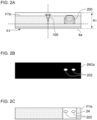
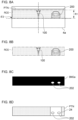
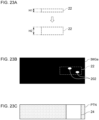
- Figs. 2(A), 2(B), and 2(C) are illustrations for describing a basic operation of vehicle detection and light distribution control.
- Fig. 2(A) shows a host vehicle 100, an imaging region 4a of the imaging device 4, and a light distribution pattern PTN formed in the region ahead of the host vehicle 100.
- a high beam light distribution pattern is shown as one example of the light distribution pattern PTN.
- an image IMG that includes the front vehicle 200 is generated by the imaging device 4 and sent to the vehicle detecting device 6.
- the imaging region 4a, of the imaging device 4, used for vehicle detection or light distribution control, that is, a sensing region of the imaging device 4 is typically set larger in the right-left direction of the host vehicle 100 than in its up-down direction. This is because the range in which a front vehicle 200 to be detected appears or the shape of a light distribution pattern PTN is larger in the right-left direction than in the up-down direction.
- the imaging region 4a covers a range smaller than the maximum imageable range of the imaging device 4.
- the image IMG sent to the vehicle detecting device 6 is acquired by the image processing unit 12.
- the image processing unit 12 performs known image processing, such as binarization, on the image IMG.
- This image processing generates a luminous point image IMGa in which two luminous points 202 corresponding to lamps of the front vehicle 200 are extracted, as shown in Fig. 2(B) .
- the lamps of the front vehicle 200 are rear lamps or the like if the front vehicle 200 is a leading vehicle, or they are headlamps or the like if the front vehicle 200 is an oncoming vehicle.
- a rear lamp includes a stop lamp and a tail lamp.
- the image processing unit 12 sends the generated luminous point image IMGa to the detection unit 14.
- the detection unit 14 determines the presence of a front vehicle 200 using a luminous point image IMGa.
- a luminous point image IMGa includes luminous points 202
- the detection unit 14 detects a front vehicle 200 based on these luminous points 202.
- the detection unit 14 compares luminous points 202 against a known pair determining condition, and when having identified two luminous points 202 that satisfy the pair determining condition, the detection unit 14 determines these two luminous points 202 as a front vehicle 200.
- the detection unit 14 sends its detection result to the light distribution controlling device 8.
- the vehicle detecting method there is no particular limitation on the vehicle detecting method that the detection unit 14 performs.
- the detection unit 14 may detect a front vehicle 200 directly from an image IMG using a known method including, for example, algorithm recognition or deep learning.
- the detection result sent to the light distribution controlling device 8 is acquired by the pattern determining unit 18.
- the pattern determining unit 18 sets a shaded region 24 to overlap the front vehicle 200 in a light distribution pattern that serves as a base, as shown in Fig. 2(C) .
- a light distribution pattern PTN to be formed is determined.
- a shaded region 24 is a portion of a light distribution pattern PTN where the luminance (illuminance) is zero or a portion of a light distribution pattern PTN where the luminance is reduced to higher than zero but lower than that held prior to shading.
- the pattern determining unit 18 sets a light distribution pattern PTN that does not include a shaded region 24.
- a light distribution pattern that serves as a base is selected in accordance with a light distribution mode that is set based, for example, on the driver's instruction input by operating the light switch (not shown), the traveling state of the host vehicle, or the environment surrounding the host vehicle.
- light distribution modes include, for example, a high beam mode of forming a high beam light distribution pattern, a low beam mode of forming a low beam light distribution pattern, and a town mode of forming a light distribution pattern suitable for traveling in a city area.
- Fig. 2(C) shows a high beam light distribution pattern as one example.
- the pattern determining unit 18 sends information about the determined light distribution pattern PTN to the lamp controlling unit 20.
- the lamp controlling unit 20 instructs the light distribution variable lamp 2 to form the light distribution pattern PTN.
- the lamp controlling unit 20 is constituted, for example, by a known LED driver module (LDM). If the light sources of the light distribution variable lamp 2 are controlled by analog dimming, the lamp controlling unit 20 adjusts the direct current level of the driving current flowing in the light sources. Meanwhile, if the light sources are controlled by pulse width modulation (PWM) dimming, the lamp controlling unit 20 adjusts the mean level of the driving current by switching the current that flows in the light sources to adjust the ratio of the on periods. If the light distribution variable lamp 2 includes a DMD, the lamp controlling unit 20 may control the on/off switching of each mirror element constituting the DMD. If the lamp controlling unit 20 includes a liquid-crystal device, the lamp controlling unit 20 may control the optical transmittance of the liquid-crystal device. Thus, the light distribution pattern PTN is formed ahead of the host vehicle.
- LDM LED driver module
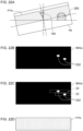
- FIGs. 3(A), 3(B), and 3(C) are illustrations for describing a case in which the basic operation is performed while the host vehicle is tilted sideways.
- the vehicle detecting device 6 detects a front vehicle 200 using an imaging region 4a that is large in the right-left direction and small in the up-down direction.
- this can create a situation in which a front vehicle 200 cannot be detected.
- the host vehicle 100 becomes tilted sideways as shown in Fig.
- the imaging region 4a of the imaging device 4 provided in the host vehicle 100 also becomes tilted sideways.
- the host vehicle 100 is a straddle-type vehicle, the host vehicle 100 banks greatly to the right and left when traveling on a curved road. Therefore, the imaging region 4a tends to tilt greatly as well.
- An image IMG obtained when the imaging region 4a is tilted is an image that is tilted with respect to the ground surface.
- a lamp or lamps of a front vehicle 200 may lie outside the image IMG. Therefore, as to a luminous point image IMGa obtained from such an image IMG, a luminous point image IMGa that fails to include a luminous point 202 can be generated, as shown in Fig. 3(B) .
- Vehicle detection performed with the use of such a luminous point image IMGa cannot detect a front vehicle 200 even when the front vehicle 200 is actually present.
- a light distribution pattern PTN that includes no shaded region 24 is set, as shown in Fig. 3(C) .
- a front vehicle 200 may lie outside an image IMG when the imaging device 4 becomes tilted, and the front vehicle 200 may fail to be detected.
- the vehicle detecting device 6 in accordance with a change in the angle of tilt (bank angle) of the vehicle's right-left axis relative to a horizontal line, modifies the imaging region 4a so as to mitigate a shift in the imaging region 4a caused by the change.
- the measurement result sent from the attitude sensor 10 to the vehicle detecting device 6 is acquired by the imaging adjusting unit 30.
- the imaging adjusting unit 30 can detect a change in the angle of tilt of the host vehicle 100.
- the imaging adjusting unit 30 modifies the imaging region 4a so as to mitigate a shift in the imaging region 4a with respect to the region ahead.
- the imaging adjusting unit 30 modifies the imaging region 4a so that the overlap (the area) between the reference portion and the imaging region 4a held when the host vehicle 100 is tilted becomes larger than when such an adjustment is not made to the imaging region 4a.
- This adjustment makes a front vehicle 200 more likely to be included in the imaging region 4a even when the host vehicle 100 becomes tilted.
- the imaging adjusting unit 30 modifies at least one of a region range of the imaging region 4a in the up-down direction of the vehicle or a region angle of the imaging region 4a.
- a case in which the imaging adjusting unit 30 modifies the region range of the imaging region 4a will be described.
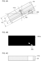
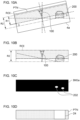
- Figs. 4(A), 4(B), and 4(C) are illustrations for describing how the region range of the imaging region 4a is adjusted.
- the region range of the imaging region 4a in the up-down direction of the vehicle is a first range R1.
- the imaging region 4a of the first range R1 is held by default in the vehicle detecting device 6.
- the vehicle detecting device 6 detects a front vehicle 200 using the imaging region 4a of the first range R1, as shown in Figs. 2(A) to 2(C) .
- the imaging adjusting unit 30 sets the region range in the up-down direction of the vehicle to a second range R2 greater than the first range R1, as shown in Fig. 4(A) .
- the imaging region 4a according to the present embodiment is rectangular with the upper and lower sides extending in the right-left direction of the vehicle and the left and right sides extending in the up-down direction.
- the imaging adjusting unit 30 displaces the upper side of the imaging region 4a upward or displaces the lower side downward, or performs both of these displacing operations.
- the adjustment of the region range includes displacing the lower side of the imaging region 4a.
- the imaging adjusting unit 30 holds, in advance, a threshold of the angle of tilt of the vehicle's right-left axis, and when the angle of tilt of the host vehicle 100 has exceeded the threshold, the imaging adjusting unit 30 expands the region range of the imaging region 4a from the first range R1 to the second range R2.
- This threshold can be set as appropriate based on an experiment or simulation conducted by an engineer. Expanding the range of the imaging region 4a in the up-down direction from the first range R1 to the second range R2 corresponds to the mitigating of a shift in the imaging region 4a.
- expanding corresponds to the shift mitigation.
- a front vehicle 200 lying outside the imaging region 4a can be suppressed. Accordingly, it becomes more likely that a luminous point image IMGa includes two luminous points 202 corresponding to lamps of a front vehicle 200, as shown in Fig. 4(B) . Hence, even when the host vehicle 100 becomes tilted sideways, a front vehicle 200 can be detected with high accuracy. As a result, a light distribution pattern PTN that includes a shaded region 24 to overlap a front vehicle 200 can be formed ahead of the host vehicle, as shown in Fig. 4(C) .
- vehicle detection may be performed with the use of the imaging region 4a of the first range R1
- vehicle detection may be performed with the use of the imaging region 4a of the second range R2.
- the imaging adjusting unit 30 may modify the region range in the up-down direction continuously or stepwise including three or more steps, in accordance with a change in the angle of tilt of the vehicle's right-left axis. In other words, the region range may be increased as the angle of tilt of the host vehicle 100 increases.
- Figs. 5(A), 5(B), and 5(C) are illustrations for describing how the region angle of the imaging region 4a is adjusted.
- the region angle of the imaging region 4a is the angle about the vehicle's front-rear axis or the angle about the imaging axis of the imaging device 4.
- the region angle is the angle relative to the vehicle's right-left axis, that is, for example, the angle formed by the upper side or lower side of the imaging region 4a and the vehicle's right-left axis.
- the region angle of the imaging region 4a is a third angle ⁇ 3.
- the imaging region 4a of the third angle ⁇ 3 is held by default in the vehicle detecting device 6.
- the vehicle detecting device 6 detects a front vehicle 200 using the imaging region 4a of the third angle ⁇ 3 ( ⁇ 3 ⁇ 0 degrees), as shown in Figs. 2(A) to 2(C) .
- the imaging adjusting unit 30 sets the region angle of the imaging region 4a to a fourth angle ⁇ 4 greater than the third angle ⁇ 3, as shown in Fig. 5(A) .
- the pivoting direction of the imaging region 4a is opposite the direction in which the host vehicle 100 tilts. In other words, when the host vehicle 100 is tilted to the left as shown in Fig. 5(A) , the imaging region 4a is tilted to the right (i.e., pivoted clockwise).
- the imaging region 4a is tilted to the left (i.e., pivoted counterclockwise).
- the region angle of the imaging region 4a can be adjusted through signal processing, as the imaging adjusting unit 30 instructs the processor of the imaging device 4.
- the region angle of the imaging region 4a can be adjusted physically by the imaging adjusting unit 30 causing the imaging device 4 to rotate.
- the imaging adjusting unit 30 holds, in advance, a threshold of the angle of tilt of the vehicle's right-left axis, and when the angle of tilt of the host vehicle 100 has exceeded the threshold, the imaging adjusting unit 30 modifies the region angle of the imaging region 4a from the third angle ⁇ 3 to the fourth angle ⁇ 4.
- This threshold can be set as appropriate based on an experiment or simulation conducted by an engineer.
- Increasing the angle of the imaging region 4a with respect to the vehicle's right-left axis from the third angle ⁇ 3 to the fourth angle ⁇ 4 corresponds to the mitigating of a shift in the imaging region 4a.
- such modifying corresponds to the shift mitigation.
- a front vehicle 200 lying outside the imaging region 4a can be suppressed. Accordingly, it becomes more likely that a luminous point image IMGa includes two luminous points 202 corresponding to lamps of a front vehicle 200, as shown in Fig. 5(B) . Hence, even when the host vehicle 100 becomes tilted sideways, a front vehicle 200 can be detected with high accuracy. As a result, a light distribution pattern PTN that includes a shaded region 24 to overlap a front vehicle 200 can be formed ahead of the host vehicle, as shown in Fig. 5(C) .
- vehicle detection may be performed with the use of the imaging region 4a of the third angle ⁇ 3, and when the host vehicle 100 becomes further tilted at a second angle greater than the first angle, vehicle detection may be performed with the use of the imaging region 4a of the fourth angle ⁇ 4.
- the imaging adjusting unit 30 may modify the region angle continuously or stepwise including three or more steps, in accordance with a change in the angle of tilt of the vehicle's right-left axis. In other words, the region angle may be increased as the angle of tilt of the host vehicle 100 increases.
- the imaging adjusting unit 30 may modify both the region range and the region angle of the imaging region 4a. This can further reduce the likelihood that a front vehicle 200 lies outside the imaging region 4a due to the tilting of the host vehicle 100. Accordingly, a front vehicle 200 can be detected with higher accuracy.
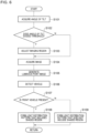
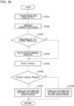
- Fig. 6 is a flowchart for describing one example of control executed by the vehicle detecting device 6 and the light distribution controlling device 8. This flow is executed repeatedly at predetermined timings, for example, when the execution of ADB control is instructed via a light switch (not shown) and when the ignition is on.
- the vehicle detecting device 6 acquires the angle of tilt of the host vehicle 100 from the attitude sensor 10 (S101). Then, the vehicle detecting device 6 determines whether the angle of tilt of the right-left axis of the host vehicle 100 is greater than a threshold (S102). If the angle of tilt is greater than the threshold (Y at S102), the vehicle detecting device 6 adjusts at least one of the region range or the region angle of the imaging region 4a (S013), and proceeds to step S104. If the angle of tilt is not greater than the threshold (N at S102), the vehicle detecting device 6 proceeds to step S104 without adjusting the imaging region 4a.
- a threshold S102
- the vehicle detecting device 6 acquires an image IMG from the imaging device 4 (S104). Then, the vehicle detecting device 6 generates a luminous point image IMGa from the acquired image IMG (S105). The vehicle detecting device 6 performs a vehicle detecting process using the generated luminous point image IMGa (S106). Then, the vehicle detecting device 6 determines whether a front vehicle 200 is present based on the result of the vehicle detecting process (S107). If a front vehicle 200 is present (Y at S107), the light distribution controlling device 8 controls the light distribution variable lamp 2 so as to form a light distribution pattern PTN that includes a shaded region 24 (S108), and terminates the present routine. If no front vehicle 200 is present (N at S107), the light distribution controlling device 8 controls the light distribution variable lamp 2 so as to form a light distribution pattern PTN that does not include a shaded region 24 (S109), and terminates the present routine.
- the vehicle detecting device 6 performs a process of detecting a front vehicle 200 using an image IMG that is based on the imaging device 4 provided in the host vehicle 100. Furthermore, the vehicle detecting device 6, in accordance with a change in the angle of tilt of the vehicle's right-left axis with respect to a horizontal line, modifies the imaging region 4a so as to mitigate a shift in the imaging region 4a (imaging angle) of the imaging device 4 caused by the change. Adjusting the imaging region 4a dynamically in accordance with the tilt of the host vehicle 100 makes it possible to avoid missing a front vehicle 200. Accordingly, the accuracy of detecting a front vehicle 200 can be increased.
- the vehicle detecting device 6 modifies at least one of the region range of the imaging region 4a in the up-down direction of the vehicle or the region angle of the imaging region 4a. In other words, the vehicle detecting device 6 adjusts at least one of the shape or the orientation of the imaging region 4a.
- the vehicle detecting device 6 When modifying the region range, the vehicle detecting device 6 sets the region range to the first range R1 when the angle of tilt is the first angle and sets the region range to the second range R2 greater than the first range R1 when the angle of tilt is the second angle greater than the first angle.
- the imaging region 4a is made relatively small when the angle of tilt of the host vehicle 100 is relatively small and the imaging region 4a is made relatively large when the angle of tilt is relatively large as described above, the processing load on the vehicle detecting device 6 can be reduced, as compared to the case of performing vehicle detection using an imaging region 4a that is large by default regardless of the angle of tilt of the host vehicle 100.
- the above can suppress erroneous determination that a luminous point 202 that is not of a front vehicle 200 is determined to have come from a front vehicle 200.
- the vehicle detecting device 6 sets the region angle with respect to the vehicle's right-left axis to the third angle ⁇ 3 when the angle of tilt is the first angle and sets the region angle with respect to the vehicle's right-left axis to the fourth angle ⁇ 4 greater than the third angle ⁇ 3 when the angle of tilt is the second angle greater than the first angle. Modifying the region angle in accordance with the tilt of the host vehicle 100 while retaining the shape of the imaging region 4a in this manner can suppress erroneous determination.
- the host vehicle 100 provided with the vehicle detecting device 6 according to the present embodiment is a straddle-type vehicle.
- the vehicle's right-left axis of a straddle-type vehicle tends to become tilted to a greater extent than that of a typical four-wheeled automobile. Therefore, the vehicle detecting device 6 can exhibit its functionality effectively especially in straddle-type vehicles.
- the host vehicle 100 may be a vehicle other than a straddle-type vehicle, such as a four-wheeled automobile.
- the light distribution controlling device 8 sets a light distribution pattern PTN that includes a shaded region 24 to overlap a front vehicle 200, based on a detection result of the vehicle detecting device 6.
- This configuration makes it possible to achieve, with higher accuracy, both the reduction of glare caused on the driver of a front vehicle 200 and the improvement in the visibility of the driver of the host vehicle 100. Accordingly, safety in vehicle driving can be improved.
- Embodiment 1 of the present invention has been described in detail.
- the embodiment described above merely illustrates a specific example for implementing the present invention.
- the contents of the embodiment do not limit the technical scope of the present invention, and a number of design changes, including modifications, additions, and deletions of constituent elements, can be made within the scope that does not depart from the sprit of the invention set forth in the claims.
- a new embodiment resulting from adding a design change has advantageous effects of the embodiments combined as well as the advantageous effects of the modification.
- a vehicle detecting device (6) that:
- the vehicle detecting device (6) according to First Item or Second Item, wherein the vehicle (100) is a straddle-type vehicle.
- a light distribution controlling device (8) that: based on a detection result of the vehicle detecting device (6) according to any one of First Item to Third Item, sets a light distribution pattern (PTN) that includes a shaded region (24) to overlap the front vehicle (200).
- a vehicle detecting method including:
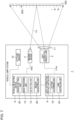
- Fig. 7 is a block diagram of a vehicle lamp system 1.
- Fig. 7 depicts constituent elements of the vehicle lamp system 1 in the form of functional blocks. These functional blocks are implemented, as to their hardware configuration, by elements or circuits, such as a CPU or memory of a computer, or implemented, as to their software configuration, by a computer program or the like. It is to be appreciated by a person skilled in the art that these functional blocks can be implemented in a variety of forms through combinations of hardware and software.
- the vehicle lamp system 1 includes a light distribution variable lamp 2, an imaging device 4, a vehicle detecting device 6, a light distribution controlling device 8, and an attitude sensor 10. These components are provided in a vehicle.
- a vehicle in which the vehicle lamp system 1 is provided according to the present embodiment is a straddle-type vehicle, such as a motorcycle.
- the light distribution variable lamp 2, the imaging device 4, the vehicle detecting device 6, the light distribution controlling device 8, and the attitude sensor 10 may all be contained within a single housing, or some of these members may be provided outside such a housing.
- the light distribution variable lamp 2, the imaging device 4, the vehicle detecting device 6, the light distribution controlling device 8, and the attitude sensor 10 are housed in a lamp room.
- the lamp room is defined by a lamp body having an opening that opens to the front side of the vehicle and a light-transmissive cover attached so as to cover the opening of the lamp body.
- the imaging device 4, the vehicle detecting device 6, the light distribution controlling device 8, and the attitude sensor 10 may be provided outside the lamp room, such as in the vehicle. In this case, the imaging device 4 may be an onboard camera.
- the vehicle detecting device 6 and the light distribution controlling device 8 may be, for example, entirely or partly constituted by a vehicle ECU.
- the light distribution variable lamp 2 is capable of illuminating a region ahead of the host vehicle with a visible light beam L1 of a variable intensity distribution.
- the light distribution variable lamp 2 is enabled to vary the illuminance of light in a plurality of illuminated individual regions R arrayed ahead of the vehicle independently of each other.
- the plurality of individual regions R are arrayed, for example, in a matrix.
- the light distribution variable lamp 2 receives information instructing on a light distribution pattern PTN from the light distribution controlling device 8 and emits a visible light beam L1 having an intensity distribution corresponding to the light distribution pattern PTN.
- the light distribution pattern PTN is formed ahead of the host vehicle.
- a light distribution pattern PTN can be understood as a two-dimensional illuminance distribution of an illumination pattern 902 that the light distribution variable lamp 2 forms on an imaginary vertical screen 900 ahead of the host vehicle.
- the light distribution variable lamp 2 includes, for example, a plurality of light sources arrayed in a matrix and a lighting circuit that drives the light sources to turn them on independently of each other.
- a light source include a semiconductor light source, such as a light-emitting diode (LED), a laser diode (LD), or an organic or inorganic electroluminescence (EL) light source.
- the light sources are mapped to the respective individual regions R, and each individual region R is individually illuminated with light from the corresponding light source.
- the light distribution variable lamp 2 has a resolution, that is, a light distribution resolving power of, for example, from 1,000 pixels to 2,000,000 pixels.
- the resolution of the light distribution variable lamp 2 means the number of the unit regions, of a light distribution pattern PTN, whose illuminance can be varied independently of each other.
- the light distribution variable lamp 2 may include, for example but not limited to, a pattern forming device of a matrix type, such as a digital mirror device (DMD) or a liquid-crystal device, or a pattern forming device of a scan optics type that scans the space ahead of the host vehicle with light from a light source.
- a pattern forming device of a matrix type such as a digital mirror device (DMD) or a liquid-crystal device
- a pattern forming device of a scan optics type that scans the space ahead of the host vehicle with light from a light source.
- illumination of light directed to the region ahead of the host vehicle may be blocked partly by a shading plate.
- the imaging device 4 has a sensitivity to a visible light range and repeatedly captures an image of the region ahead of the host vehicle.
- the imaging device 4 captures an image of reflected light L2 of a visible light beam L1 reflected from an object located ahead of the vehicle.
- the imaging device 4 also captures an image of light from a front vehicle, including a leading vehicle and an oncoming vehicle.
- An image IMG that the imaging device 4 generates is sent to the vehicle detecting device 6.
- An image IMG that the vehicle detecting device 6 acquires from the imaging device 4 may be RAW image data or image data subjected to predetermined image processing by the imaging device 4.
- this receiving also corresponds to the acquiring of an image IMG from the imaging device 4.
- an image IMG that is based on the imaging device 4" may mean either of RAW image data and data subjected to image processing.
- image IMG may be used without any distinction between the two types of image data.
- the vehicle detecting device 6 detects a front vehicle using an image IMG that is based on the imaging device 4.
- the vehicle detecting device 6 sends its detection result to the light distribution controlling device 8.
- the vehicle detecting device 6 may detect a target aside from a front vehicle.
- the vehicle detecting device 6 can be constituted by a digital processor, and for example, the vehicle detecting device 6 may be constituted by a combination of a microcomputer including a CPU and a software program or by a field programmable gate array (FPGA), an application specific IC (ASIC), or the like.
- the vehicle detecting device 6 includes, in one example, a region setting unit 26, an image processing unit 12, a detection unit 14, and a region adjusting unit 28. Each of these units operates as an integrated circuit constituting itself executes a program stored in a memory. An operation of each of these units will be described later.
- the light distribution controlling device 8 executes ADB control of dynamically and adaptively controlling the light distribution of the light distribution variable lamp 2 in accordance with a target present in the region ahead.
- the light distribution controlling device 8 sets a light distribution pattern PTN that includes a shaded region to overlap a front vehicle, based on a detection result of the vehicle detecting device 6.
- the light distribution controlling device 8 sends information instructing on a light distribution pattern PTN to the light distribution variable lamp 2.
- the light distribution controlling device 8 can be constituted by a digital processor, and for example, the light distribution controlling device 8 may be constituted by a combination of a microcomputer including a CPU and a software program or by a field programmable gate array (FPGA), an application specific IC (ASIC), or the like.
- the light distribution controlling device 8 includes, in one example, a pattern determining unit 18 and a lamp controlling unit 20. Each of these units operates as an integrated circuit constituting itself executes a program stored in a memory. An operation of each of these units will be described later.
- the attitude sensor 10 measures the tilt of the host vehicle in the right-left direction. That is, the attitude sensor 10 measures the angle of tilt of the vehicle's right-left axis with respect to a horizontal line or a vertical line (in other words, the angle of tilt of the vehicle's up-down axis with respect to a horizontal line or a vertical line).
- the attitude sensor 10 is constituted, for example but not limited to, by a known inertial measurement unit (IMU).
- IMU inertial measurement unit
- the attitude sensor 10 sends its measurement result to the vehicle detecting device 6.
- Figs. 8(A), 8(B), 8(C), and 8(D) are illustrations for describing a basic operation of vehicle detection and light distribution control.
- Fig. 8(A) shows a host vehicle 100, an imaging region 4a of the imaging device 4, and a light distribution pattern PTN formed in the region ahead of the host vehicle 100.
- a high beam light distribution pattern is shown as one example of the light distribution pattern PTN.
- Fig. 8(A) shows a processing region ROI, for convenience.
- a processing region ROI is a region in which, for example, a front vehicle 200 is predicted to appear, and can be set in advance based on an experiment or simulation conducted by an engineer.
- a processing region ROI is a rectangular region that extends in the width direction of the vehicle and lies above a horizontal line.
- the region setting unit 26 sends the image IMG having the processing region ROI set therein to the image processing unit 12.
- the image processing unit 12 extracts the processing region ROI from the image IMG, as shown in Fig. 8(B) .
- the image processing unit 12 then performs known image processing, such as binarization, on the processing region ROI.
- This image processing generates a luminous point image IMGa in which two luminous points 202 corresponding to lamps of the front vehicle 200 are extracted, as shown in Fig. 8(C) .
- the lamps of the front vehicle 200 are rear lamps or the like if the front vehicle 200 is a leading vehicle, or they are headlamps or the like if the front vehicle 200 is an oncoming vehicle.
- a rear lamp includes a stop lamp and a tail lamp.
- the image processing unit 12 sends the generated luminous point image IMGa to the detection unit 14.
- the detection unit 14 determines the presence of the front vehicle 200 using the luminous point image IMGa. Performing a vehicle detecting process on the luminous point image IMGa generated from the processing region ROI corresponds to performing a vehicle detecting process on the processing region ROI.
- the detection unit 14 detects a front vehicle 200 based on these luminous points 202.
- the detection unit 14 determines that luminous points 202 present in a processing region ROI are derived from a front vehicle 200, or in other words, determines that a front vehicle 200 is present at the position where the luminous points 202 are present.
- the detection unit 14 sends its detection result to the light distribution controlling device 8.
- the detection unit 14 may detect a front vehicle 200 from a processing region ROI using a known method including, for example, algorithm recognition or deep learning.
- the detection result sent to the light distribution controlling device 8 is acquired by the pattern determining unit 18.
- the pattern determining unit 18 sets a shaded region 24 to overlap the front vehicle 200 in a light distribution pattern that serves as a base, as shown in Fig. 8(D) .
- a light distribution pattern PTN to be formed is determined.
- a shaded region 24 is a portion of a light distribution pattern PTN where the luminance (illuminance) is zero or a portion of a light distribution pattern PTN where the luminance is reduced to higher than zero but lower than that held prior to shading.
- the pattern determining unit 18 sets a light distribution pattern PTN that does not include a shaded region 24.
- a light distribution pattern that serves as a base is selected in accordance with a light distribution mode that is set based, for example, on the driver's instruction input by operating the light switch (not shown), the traveling state of the host vehicle, or the environment surrounding the host vehicle.
- light distribution modes include, for example, a high beam mode of forming a high beam light distribution pattern, a low beam mode of forming a low beam light distribution pattern, and a town mode of forming a light distribution pattern suitable for traveling in a city area.
- Fig. 8(D) shows a high beam light distribution pattern as one example.
- the pattern determining unit 18 sends information about the determined light distribution pattern PTN to the lamp controlling unit 20.
- the lamp controlling unit 20 instructs the light distribution variable lamp 2 to form the light distribution pattern PTN.
- the lamp controlling unit 20 is constituted, for example, by a known LED driver module (LDM). If the light sources of the light distribution variable lamp 2 are controlled by analog dimming, the lamp controlling unit 20 adjusts the direct current level of the driving current flowing in the light sources. Meanwhile, if the light sources are controlled by pulse width modulation (PWM) dimming, the lamp controlling unit 20 adjusts the mean level of the driving current by switching the current that flows in the light sources to adjust the ratio of the on periods. If the light distribution variable lamp 2 includes a DMD, the lamp controlling unit 20 may control the on/off switching of each mirror element constituting the DMD. If the lamp controlling unit 20 includes a liquid-crystal device, the lamp controlling unit 20 may control the optical transmittance of the liquid-crystal device. Thus, the light distribution pattern PTN is formed ahead of the host vehicle.
- LDM LED driver module
- Figs. 9(A), 9(B), 9(C), and 9(D) are illustrations for describing a case in which the basic operation is performed while the host vehicle is tilted sideways.
- the vehicle detecting device 6 performs the process of detecting a front vehicle 200 from a processing region ROI.
- this can create a situation in which a front vehicle 200 cannot be detected.
- the imaging region 4a of the imaging device 4 provided in the host vehicle 100 also becomes tilted sideways.
- the imaging region 4a tends to tilt greatly as well.
- An image IMG obtained when the imaging region 4a is tilted sideways is an image that is tilted with respect to the ground surface. Therefore, a processing region ROI extracted from this image IMG is also tilted with respect to the ground surface, as shown in Fig. 9(B) .
- lamps of a front vehicle 200 may lie outside the processing region ROI. Therefore, a luminous point image IMGa that does not include a luminous point 202 can be generated, as shown in Fig. 9(C) .
- Vehicle detection performed with the use of such a luminous point image IMGa cannot detect a front vehicle 200 even when the front vehicle 200 is actually present.
- a light distribution pattern PTN that includes no shaded region 24 is set, as shown in Fig. 9(D) .
- a front vehicle 200 may lie outside a processing region ROI as the processing region ROI becomes tilted, and the front vehicle 200 may fail to be detected.
- the vehicle detecting device 6 in accordance with a change in the angle of tilt (bank angle) of the vehicle's right-left axis relative to a horizontal line, modifies a processing region ROI so as to mitigate a shift in the processing region ROI caused by the change.
- the vehicle detecting device 6 sets, in an image IMG, a processing region ROI modified so as to mitigate the shift.
- the measurement result sent from the attitude sensor 10 to the vehicle detecting device 6 is acquired by the region adjusting unit 28.
- the region adjusting unit 28 can detect a change in the angle of tilt of the host vehicle 100.
- the region adjusting unit 28 modifies the processing region ROI so as to mitigate a shift in the processing region ROI with respect to the region ahead.
- the region adjusting unit 28 modifies the processing region ROI so that the overlap (the area) between the reference portion and the processing region ROI held when the host vehicle 100 is tilted becomes larger than when such an adjustment is not made to the processing region ROI. This adjustment makes a front vehicle 200 more likely to be included in the processing region ROI even when the host vehicle 100 becomes tilted.
- the region adjusting unit 28 modifies at least one of a region range of the processing region ROI in the up-down direction of the vehicle or a region angle of the processing region ROI.
- Figs. 10(A), 10(B), 10(C) and 10(D) are illustrations for describing how the region range of the processing region ROI is adjusted.
- the angle of tilt of the right-left axis of the host vehicle 100 is a first angle with respect to a horizontal line
- the region range of the processing region ROI in the up-down direction of the vehicle that is, the region range in the up-down direction of the image is a first range R1.
- the processing region ROI of the first range R1 is held by default in the vehicle detecting device 6.
- the vehicle detecting device 6 detects a front vehicle 200 using the processing region ROI of the first range R1, as shown in Figs. 8(A) to 8(D) .
- the region adjusting unit 28 sets the region range in the up-down direction of the vehicle to a second range R2 greater than the first range R1, as shown in Fig. 10(A) .
- the processing region ROI according to the present embodiment is rectangular with the upper and lower sides extending in the right-left direction of the vehicle or of the image and the left and right sides extending in the up-down direction.
- the region adjusting unit 28 displaces the upper side of the processing region ROI upward or displaces the lower side downward, or performs both of these displacing operations.
- the adjustment of the region range includes displacing the lower side of the processing region ROI.
- the region adjusting unit 28 holds, in advance, a threshold of the angle of tilt of the vehicle's right-left axis, and when the angle of tilt of the host vehicle 100 has exceeded the threshold, the region adjusting unit 28 expands the region range of the processing region ROI from the first range R1 to the second range R2.
- This threshold can be set as appropriate based on an experiment or simulation conducted by an engineer. Expanding the range of the processing region ROI in the up-down direction from the first range R1 to the second range R2 corresponds to the mitigating of a shift in the processing region ROI.
- expanding corresponds to the shift mitigation.
- the image processing unit 12 extracts the processing region ROI of the second range R2 from the image IMG, as shown in Fig. 10 (B) .
- the processing region ROI is expanded from the first range R1 to the second range R2
- a front vehicle 200 lying outside the processing region ROI can be suppressed.
- a luminous point image IMGa generated from this processing region ROI includes two luminous points 202 corresponding to lamps of a front vehicle 200, as shown in Fig. 10(C) .
- a front vehicle 200 can be detected with high accuracy.
- a light distribution pattern PTN that includes a shaded region 24 to overlap a front vehicle 200 can be formed ahead of the host vehicle, as shown in Fig. 10(D) .
- vehicle detection may be performed with the use of the processing region ROI of the first range R1
- vehicle detection may be performed with the use of the processing region ROI of the second range R2.
- the region adjusting unit 28 may modify the region range in the up-down direction continuously or stepwise including three or more steps, in accordance with a change in the angle of tilt of the vehicle's right-left axis. In other words, the region range may be increased as the angle of tilt of the host vehicle 100 increases.
- Figs. 11(A), 11(B), 11(C), and 11(D) are illustrations for describing how the region angle of the processing region ROI is adjusted.
- the region angle of the processing region ROI is the angle about the vehicle's front-rear axis or the angle about the imaging axis of the imaging device 4.
- the region angle is the angle relative to the vehicle's right-left axis, that is, for example, the angle formed by the upper side or lower side of the processing region ROI and the vehicle's right-left axis.
- the region angle of the processing region ROI is a third angle ⁇ 3.
- the processing region ROI of the third angle ⁇ 3 is held by default in the vehicle detecting device 6.
- the vehicle detecting device 6 detects a front vehicle 200 using the processing region ROI of the third angle ⁇ 3 ( ⁇ 3 ⁇ 0 degrees), as shown in Figs. 8(A) to 8(D) .
- the region adjusting unit 28 sets the region angle of the processing region ROI to a fourth angle ⁇ 4 greater than the third angle ⁇ 3, as shown in Fig. 11(A) .
- the pivoting direction of the processing region ROI is opposite the direction in which the host vehicle 100 tilts. In other words, when the host vehicle 100 is tilted to the left as shown in Fig. 11(A) , the processing region ROI is tilted to the right (i.e., pivoted clockwise). Meanwhile, when the host vehicle 100 is tilted to the right, the processing region ROI is tilted to the left (i.e., pivoted counterclockwise).
- the region adjusting unit 28 holds, in advance, a threshold of the angle of tilt of the vehicle's right-left axis, and when the angle of tilt of the host vehicle 100 has exceeded the threshold, the region adjusting unit 28 modifies the region angle of the processing region ROI from the third angle ⁇ 3 to the fourth angle ⁇ 4.
- This threshold can be set as appropriate based on an experiment or simulation conducted by an engineer.
- Increasing the angle of the processing region ROI with respect to the vehicle's right-left axis from the third angle ⁇ 3 to the fourth angle ⁇ 4 corresponds to the mitigating of a shift in the processing region ROI.
- such modifying corresponds to the shift mitigation.
- the image processing unit 12 extracts the processing region ROI of the fourth angle ⁇ 4 from the image IMG, as shown in Fig. 11(B) .
- the processing region ROI is tilted from the third angle ⁇ 3 to the fourth angle ⁇ 4 with respect to the vehicle's right-left axis, even when the host vehicle 100 becomes tilted sideways, a front vehicle 200 lying outside the processing region ROI can be suppressed. Accordingly, it becomes more likely that a luminous point image IMGa generated from this processing region ROI includes two luminous points 202 corresponding to lamps of a front vehicle 200, as shown in Fig. 11(C) . Hence, even when the host vehicle 100 becomes tilted sideways, a front vehicle 200 can be detected with high accuracy. As a result, a light distribution pattern PTN that includes a shaded region 24 to overlap a front vehicle 200 can be formed ahead of the host vehicle, as shown in Fig. 11(D) .
- vehicle detection may be performed with the use of the processing region ROI of the third angle ⁇ 3, and when the host vehicle 100 becomes further tilted at a second angle greater than the first angle, vehicle detection may be performed with the use of the processing region ROI of the fourth angle ⁇ 4.
- the region adjusting unit 28 may modify the region angle continuously or stepwise including three or more steps, in accordance with a change in the angle of tilt of the vehicle's right-left axis. In other words, the region angle may be increased as the angle of tilt of the host vehicle 100 increases.
- the region adjusting unit 28 may modify both the region range and the region angle of the processing region ROI. This can further reduce the likelihood that a front vehicle 200 lies outside the processing region ROI due to the tilting of the host vehicle 100. Accordingly, a front vehicle 200 can be detected with higher accuracy.
- Fig. 12 is a flowchart for describing one example of control executed by the vehicle detecting device 6 and the light distribution controlling device 8. This flow is executed repeatedly at predetermined timings, for example, when the execution of ADB control is instructed via a light switch (not shown) and when the ignition is on.
- the vehicle detecting device 6 acquires an image IMG from the imaging device 4.
- the vehicle detecting device 6 also acquires the angle of tilt of the host vehicle 100 from the attitude sensor 10 (S101). Then, the vehicle detecting device 6 determines whether the angle of tilt of the right-left axis of the host vehicle 100 is greater than a threshold (S102) . If the angle of tilt is greater than the threshold (Y at S102), the vehicle detecting device 6 adjusts at least one of the region range or the region angle of the processing region ROI (S103), and proceeds to step S104. If the angle of tilt is not greater than the threshold (N at S102), the vehicle detecting device 6 proceeds to step S104 without adjusting the processing region ROI.
- the vehicle detecting device 6 extracts the processing region ROI from the image IMG and generates a luminous point image IMGa from the processing region ROI (S104).
- the vehicle detecting device 6 performs a vehicle detecting process using the generated luminous point image IMGa (S105).
- the vehicle detecting device 6 determines whether a front vehicle 200 is present based on the result of the vehicle detecting process (S106). If a front vehicle 200 is present (Y at S106), the light distribution controlling device 8 controls the light distribution variable lamp 2 so as to form a light distribution pattern PTN that includes a shaded region 24 (S107), and terminates the present routine. If no front vehicle 200 is present (N at S106), the light distribution controlling device 8 controls the light distribution variable lamp 2 so as to form a light distribution pattern PTN that does not include a shaded region 24 (S108), and terminates the present routine.
- the vehicle detecting device 6 sets a processing region ROI in an image IMG that is based on the imaging device 4 provided in the host vehicle 100 and performs a process of detecting a front vehicle 200 from the processing region ROI.
- the vehicle detecting process is performed after a processing region ROI has been converted to a luminous point image IMGa.
- the load on the vehicle detecting device 6 can be reduced, as compared to the case of detecting a vehicle from an entire image IMG.
- the vehicle detecting device 6 in accordance with a change in the angle of tilt of the vehicle's right-left axis relative to a horizontal line, modifies the processing region ROI so as to mitigate a shift in the processing region ROI caused by the change. Adjusting the processing region ROI dynamically in accordance with the tilt of the host vehicle 100 in this manner makes it possible to avoid missing a front vehicle 200. Accordingly, the accuracy of detecting a front vehicle 200 can be increased.
- the vehicle detecting device 6 modifies at least one of the region range of the processing region ROI in the up-down direction of the vehicle or the region angle of the processing region ROI. In other words, the vehicle detecting device 6 adjusts at least one of the shape or the orientation of the processing region ROI.
- the vehicle detecting device 6 When modifying the region range, the vehicle detecting device 6 sets the region range to the first range R1 when the angle of tilt is the first angle and sets the region range to the second range R2 greater than the first range R1 when the angle of tilt is the second angle greater than the first angle.
- the processing region ROI is made relatively small when the angle of tilt of the host vehicle 100 is relatively small and the processing region ROI is made relatively large when the angle of tilt is relatively large as described above, the processing load on the vehicle detecting device 6 can be reduced, as compared to the case of performing vehicle detection using a processing region ROI that is large by default regardless of the angle of tilt of the host vehicle 100.
- the above can suppress erroneous determination that a luminous point 202 that is not of a front vehicle 200 is determined to have come from a front vehicle 200.
- the vehicle detecting device 6 sets the region angle with respect to the vehicle's right-left axis to the third angle ⁇ 3 when the angle of tilt of the first angle and sets the region angle with respect to the vehicle's right-left axis to the fourth angle ⁇ 4 greater than the third angle ⁇ 3 when the angle of tilt is the second angle greater than the first angle. Modifying the region angle in accordance with the tilt of the host vehicle 100 while retaining the shape of the processing region ROI in this manner can suppress erroneous determination.
- the host vehicle 100 provided with the vehicle detecting device 6 according to the present embodiment is a straddle-type vehicle.
- the vehicle's right-left axis of a straddle-type vehicle tends to become tilted to a greater extent than that of a typical four-wheeled automobile. Therefore, the vehicle detecting device 6 can exhibit its functionality effectively especially in straddle-type vehicles.
- the host vehicle 100 may be a vehicle other than a straddle-type vehicle, such as a four-wheeled automobile.
- the light distribution controlling device 8 sets a light distribution pattern PTN that includes a shaded region 24 to overlap a front vehicle 200, based on a detection result of the vehicle detecting device 6.
- This configuration makes it possible to achieve, with higher accuracy, both the reduction of glare caused on the driver of a front vehicle 200 and the improvement in the visibility of the driver of the host vehicle 100. Accordingly, safety in vehicle driving can be improved.
- Embodiment 2 according to the present invention has been described in detail.
- the embodiment described above merely illustrates a specific example for implementing the present invention.
- the contents of the embodiment do not limit the technical scope of the present invention, and a number of design changes, including modifications, additions, and deletions of constituent elements, can be made within the scope that does not depart from the sprit of the invention set forth in the claims.
- a new embodiment resulting from adding a design change has advantageous effects of the embodiments combined as well as the advantageous effects of the modification.
- a vehicle detecting device (6) that:
- the vehicle detecting device (6) according to First Item or Second Item, wherein the vehicle (100) is a straddle-type vehicle.
- a light distribution controlling device (8) that: based on a detection result of the vehicle detecting device (6) according to any one of First Item to Third Item, sets a light distribution pattern (PTN) that includes a shaded region (24) to overlap the front vehicle (200).
- a vehicle detecting method including:
- Fig. 13 is a block diagram of a vehicle lamp system 1.
- Fig. 13 depicts constituent elements of the vehicle lamp system 1 in the form of functional blocks. These functional blocks are implemented, as to their hardware configuration, by elements or circuits, such as a CPU or memory of a computer, or implemented, as to their software configuration, by a computer program or the like. It is to be appreciated by a person skilled in the art that these functional blocks can be implemented in a variety of forms through combinations of hardware and software.
- the vehicle lamp system 1 includes a light distribution variable lamp 2, an imaging device 4, a vehicle detecting device 6, a light distribution controlling device 8, and an attitude sensor 10. These components are provided in a vehicle.
- a vehicle in which the vehicle lamp system 1 is provided according to the present embodiment is a straddle-type vehicle, such as a motorcycle.
- the light distribution variable lamp 2, the imaging device 4, the vehicle detecting device 6, the light distribution controlling device 8, and the attitude sensor 10 may all be contained within a single housing, or some of these members may be provided outside such a housing.
- the light distribution variable lamp 2, the imaging device 4, the vehicle detecting device 6, the light distribution controlling device 8, and the attitude sensor 10 are housed in a lamp room.
- the lamp room is defined by a lamp body having an opening that opens to the front side of the vehicle and a light-transmissive cover attached so as to cover the opening of the lamp body.
- the imaging device 4, the vehicle detecting device 6, the light distribution controlling device 8, and the attitude sensor 10 may be provided outside the lamp room, such as in the vehicle. In this case, the imaging device 4 may be an onboard camera.
- the vehicle detecting device 6 and the light distribution controlling device 8 may be, for example, entirely or partly constituted by a vehicle ECU.
- the light distribution variable lamp 2 is capable of illuminating a region ahead of the host vehicle with a visible light beam L1 of a variable intensity distribution.
- the light distribution variable lamp 2 is enabled to vary the illuminance of light in a plurality of illuminated individual regions R arrayed ahead of the vehicle independently of each other.
- the plurality of individual regions R are arrayed, for example, in a matrix.
- the light distribution variable lamp 2 receives information instructing on a light distribution pattern PTN from the light distribution controlling device 8 and emits a visible light beam L1 having an intensity distribution corresponding to the light distribution pattern PTN.
- the light distribution pattern PTN is formed ahead of the host vehicle.
- a light distribution pattern PTN can be understood as a two-dimensional illuminance distribution of an illumination pattern 902 that the light distribution variable lamp 2 forms on an imaginary vertical screen 900 ahead of the host vehicle.
- the light distribution variable lamp 2 includes, for example, a plurality of light sources arrayed in a matrix and a lighting circuit that drives the light sources to turn them on independently of each other.
- a light source include a semiconductor light source, such as a light-emitting diode (LED), a laser diode (LD), or an organic or inorganic electroluminescence (EL) light source.
- the light sources are mapped to the respective individual regions R, and each individual region R is individually illuminated with light from the corresponding light source.
- the light distribution variable lamp 2 has a resolution, that is, a light distribution resolving power of, for example, from 1,000 pixels to 2,000,000 pixels.
- the resolution of the light distribution variable lamp 2 means the number of the unit regions, of a light distribution pattern PTN, whose illuminance can be varied independently of each other.
- the light distribution variable lamp 2 may include, for example but not limited to, a pattern forming device of a matrix type, such as a digital mirror device (DMD) or a liquid-crystal device, or a pattern forming device of a scan optics type that scans the space ahead of the host vehicle with light from a light source.
- a pattern forming device of a matrix type such as a digital mirror device (DMD) or a liquid-crystal device
- a pattern forming device of a scan optics type that scans the space ahead of the host vehicle with light from a light source.
- illumination of light directed to the region ahead of the host vehicle may be blocked partly by a shading plate.
- the imaging device 4 has a sensitivity to a visible light range and repeatedly captures an image of the region ahead of the host vehicle.
- the imaging device 4 captures an image of reflected light L2 of a visible light beam L1 reflected from an object located ahead of the vehicle.
- the imaging device 4 also captures an image of light from a front vehicle, including a leading vehicle and an oncoming vehicle.
- An image IMG that the imaging device 4 generates is sent to the vehicle detecting device 6.
- An image IMG that the vehicle detecting device 6 acquires from the imaging device 4 may be RAW image data or image data subjected to predetermined image processing by the imaging device 4.
- this receiving also corresponds to the acquiring of an image IMG from the imaging device 4.
- an image IMG that is based on the imaging device 4" may mean either of RAW image data and data subjected to image processing.
- image IMG may be used without any distinction between the two types of image data.
- the vehicle detecting device 6 detects a front vehicle using an image IMG that is based on the imaging device 4.
- the vehicle detecting device 6 sends its detection result to the light distribution controlling device 8.
- the vehicle detecting device 6 may detect a target aside from a front vehicle.
- the vehicle detecting device 6 can be constituted by a digital processor, and for example, the vehicle detecting device 6 may be constituted by a combination of a microcomputer including a CPU and a software program or by a field programmable gate array (FPGA), an application specific IC (ASIC), or the like.
- the vehicle detecting device 6 includes, in one example, an image processing unit 12, a detection unit 14, and an element adjusting unit 32. Each of these units operates as an integrated circuit constituting itself executes a program stored in a memory. An operation of each of these units will be described later.
- the light distribution controlling device 8 executes ADB control of dynamically and adaptively controlling the light distribution of the light distribution variable lamp 2 in accordance with a target present in the region ahead.
- the light distribution controlling device 8 sets a light distribution pattern PTN that includes a shaded region to overlap a front vehicle, based on a detection result of the vehicle detecting device 6.
- the light distribution controlling device 8 sends information instructing on a light distribution pattern PTN to the light distribution variable lamp 2.
- the light distribution controlling device 8 can be constituted by a digital processor, and for example, the light distribution controlling device 8 may be constituted by a combination of a microcomputer including a CPU and a software program or by a field programmable gate array (FPGA), an application specific IC (ASIC), or the like.
- the light distribution controlling device 8 includes, in one example, a pattern determining unit 18 and a lamp controlling unit 20. Each of these units operates as an integrated circuit constituting itself executes a program stored in a memory. An operation of each of these units will be described later.
- the attitude sensor 10 measures the tilt of the host vehicle in the right-left direction. That is, the attitude sensor 10 measures the angle of tilt of the vehicle's right-left axis with respect to a horizontal line or a vertical line (in other words, the angle of tilt of the vehicle's up-down axis with respect to a horizontal line or a vertical line).
- the attitude sensor 10 is constituted, for example but not limited to, by a known inertial measurement unit (IMU).
- IMU inertial measurement unit
- the attitude sensor 10 sends its measurement result to the vehicle detecting device 6.
- Figs. 14(A) to 14(D) and Figs. 15(A) to 15(D) are illustrations for describing a basic operation of vehicle detection and light distribution control.
- Fig. 14(A) shows a host vehicle 100, an imaging region 4a of the imaging device 4, and a light distribution pattern PTN formed in the region ahead of the host vehicle 100.
- a high beam light distribution pattern is shown as one example of the light distribution pattern PTN.
- an image IMG that includes the front vehicle 200 is generated by the imaging device 4 and sent to the vehicle detecting device 6.
- the image IMG sent to the vehicle detecting device 6 is acquired by the image processing unit 12.
- the image processing unit 12 performs known image processing, such as binarization, on the image IMG.
- This image processing generates a luminous point image IMGa in which two luminous points 202 corresponding to lamps of the front vehicle 200 are extracted, as shown in Fig. 14(B) .
- the lamps of the front vehicle 200 are rear lamps or the like if the front vehicle 200 is a leading vehicle, or they are headlamps or the like if the front vehicle 200 is an oncoming vehicle.
- a rear lamp includes a stop lamp and a tail lamp.
- the image processing unit 12 sends the generated luminous point image IMGa to the detection unit 14.
- the detection unit 14 determines the presence of the front vehicle 200 using the luminous point image IMGa.
- the detection unit 14 stores therein a first structuring element 34 (kernel) of a predetermined shape set in advance, as shown in Fig. 14(C) .
- the first structuring element 34 has a shape elongated in the right-left direction of the luminous point image IMGa.
- the detection unit 14 maps the center pixel of the first structuring element 34 to each pixel (pixel of interest) of the luminous point image IMGa to thus perform a horizontal dilation process on the luminous point image IMGa.
- Fig. 14(C) schematically shows the first structuring element 34, but the number of pixels forming the portions that extend to the right and left from the center pixel of the first structuring element 34 is not limited to what is depicted in the drawing.
- each luminous point 202 in a luminous point image IMGa is dilated horizontally, as shown in Fig. 14(D) .
- two luminous points 202 appearing side by side with a predetermined gap therebetween become coupled to each other.
- a single horizontally dilated region 36 is generated.
- the detection unit 14 detects a front vehicle 200 based on these two luminous points 202.
- the detection unit 14 determines that these two luminous points 202 are derived from a front vehicle 200, or in other words, determines that a front vehicle 200 is present at the position where these two luminous points 202 are present.
- the detection unit 14 also performs a horizontal erosion process on a luminous point image IMGa with the use of the first structuring element 34.
- the horizontal erosion process when any one of the pixels that the first structuring element 34 overlaps is a pixel of low pixel value, the pixel value of the pixel of interest is converted to this low pixel value.
- the horizontally dilated region 36 is eroded in the horizontal direction, and a horizontally eroded region 38 is generated, as shown in Fig. 15 (A) .
- the horizontal erosion process is performed on the horizontally dilated region 36, the pixels of high pixel value located outward, in the right-left direction, of the two nondilated luminous points 202 can be converted to pixels of low pixel value.
- the position of the front vehicle 200 can be detected with higher accuracy.
- the detection unit 14 detects the position itself of the horizontally eroded region 38 in the luminous point image IMGa as the position of the front vehicle 200.
- the detection unit 14 sends its detection result to the light distribution controlling device 8.
- the detection result sent to the light distribution controlling device 8 is acquired by the pattern determining unit 18.
- the pattern determining unit 18 sets a light distribution pattern PTN that includes a shaded region to overlap the front vehicle 200.
- the shaded region is a portion of the light distribution pattern PTN where the luminance (illuminance) is zero or a portion of the light distribution pattern PTN where the luminance is reduced to higher than zero but lower than that held prior to shading.
- the pattern determining unit 18 sets a light distribution pattern PTN that does not include a shaded region.
- the pattern determining unit 18 of one example acquires a luminous point image IMGa subjected to a horizontal erosion process as the detection result of the vehicle detecting device 6. Furthermore, the pattern determining unit 18 stores therein a second structuring element 40 of a predetermined shape set in advance, as shown in Fig. 15(B) .
- the second structuring element 40 has a shape elongated in the up-down direction of the luminous point image IMGa.
- the pattern determining unit 18 maps the upper end pixel of the second structuring element 40 to each pixel (pixel of interest) of the acquired luminous point image IMGa to thus perform a vertical dilation process on the luminous point image IMGa.
- FIG. 15(B) schematically shows the second structuring element 40, but the number of pixels forming the portion that extends downward from the upper end pixel of the second structuring element 40 is not limited to what is depicted in the drawing.
- the vertical dilation process when any one of the pixels that the second structuring element 40 overlaps is a pixel of high pixel value, the pixel value of the pixel of interest is converted to this high pixel value.
- the horizontally eroded region 38 is dilated upward, and a vertically dilated region 42 is generated, as shown in Fig. 15(C) .
- the pattern determining unit 18 sets a shaded region 24 in the light distribution pattern that serves as a base, based on the position of the vertically dilated region 42 in the luminous point image IMGa, as shown in Fig. 15(D) .
- a light distribution pattern PTN that includes the shaded region 24 is determined.
- the pattern determining unit 18 generates an inverted image by inverting the pixel value of each pixel of the luminous point image IMGa that includes the vertically dilated region 42. Then, the pattern determining unit 18 sets, as the shaded region 24, the set of pixels of low pixel value corresponding to the vertically dilated region 42 in the inverted image.
- the pattern determining unit 18 may reverse the order of the generating the inverted image and the image processing involving the use of the second structuring element 40.
- the pattern determining unit 18 generates an inverted image from a luminous point image IMGa.
- the pattern determining unit 18 performs a vertical erosion process on the inverted image using the second structuring element 40.
- the region of high pixel value located over the horizontally eroded region 38 erodes in the vertical direction, and a vertically eroded region is generated.
- the pattern determining unit 18 sets this vertical erosion region as a shaded region 24, the pattern determining unit 18 can determine a light distribution pattern PTN that includes the shaded region 24.
- the pattern determining unit 18 may acquire only the position information (e.g., the angle relative to the host vehicle 100) of the front vehicle 200 as the detection result of the vehicle detecting device 6 and set a shaded region 24 based on this position information.
- a light distribution pattern that serves as a base is selected in accordance with a light distribution mode that is set based, for example, on the driver's instruction input by operating the light switch (not shown), the traveling state of the host vehicle, or the environment surrounding the host vehicle.
- light distribution modes include, for example, a high beam mode of forming a high beam light distribution pattern, a low beam mode of forming a low beam light distribution pattern, and a town mode of forming a light distribution pattern suitable for traveling in a city area.
- Fig. 15(D) shows a high beam light distribution pattern as one example.
- the pattern determining unit 18 sends information about the determined light distribution pattern PTN to the lamp controlling unit 20.
- the lamp controlling unit 20 instructs the light distribution variable lamp 2 to form the light distribution pattern PTN.
- the lamp controlling unit 20 is constituted, for example, by a known LED driver module (LDM). If the light sources of the light distribution variable lamp 2 are controlled by analog dimming, the lamp controlling unit 20 adjusts the direct current level of the driving current flowing in the light sources. Meanwhile, if the light sources are controlled by pulse width modulation (PWM) dimming, the lamp controlling unit 20 adjusts the mean level of the driving current by switching the current that flows in the light sources to adjust the ratio of the on periods. If the light distribution variable lamp 2 includes a DMD, the lamp controlling unit 20 may control the on/off switching of each mirror element constituting the DMD. If the lamp controlling unit 20 includes a liquid-crystal device, the lamp controlling unit 20 may control the optical transmittance of the liquid-crystal device. Thus, the light distribution pattern PTN is formed ahead of the host vehicle.
- LDM LED driver module
- Figs. 16(A) to 16(C) and Figs. 17(A) to 17(C) are illustrations for describing a case in which the basic operation is performed while the host vehicle 100 is tilted sideways.
- the vehicle detecting device 6 detects a front vehicle 200 based on the positional relationship of two luminous points 202 relative to each other. In this control, when the attitude of the host vehicle 100 becomes tilted in the right-left direction, this can create a situation in which a front vehicle 200 cannot be detected. Specifically, when the host vehicle 100 becomes tilted sideways as shown in Fig.
- the imaging region 4a of the imaging device 4 provided in the host vehicle 100 also becomes tilted sideways.
- the host vehicle 100 is a straddle-type vehicle, the host vehicle 100 banks greatly to the right and left when traveling on a curved road. Therefore, the imaging region 4a tends to tilt greatly as well.
- An image IMG obtained when the imaging region 4a is tilted sideways is an image that is tilted with respect to the ground surface. Therefore, in a luminous point image IMGa obtained from this image IMG, two luminous points 202 corresponding to lamps of the front vehicle 200 become offset from each other in the up-down direction, as shown in Fig. 16(B) . If the horizontal dilation process is performed on this luminous point image IMGa with the use of the first structuring element 34, the two dilated luminous points 202 fail to be coupled to each other, and two horizontally dilated regions 36 may be generated, as shown in Fig. 16(C) .
- the process of setting a shaded region 24 described above may be executed even when no front vehicle 200 can be detected. In this case, however, the reduction of glare caused on the driver of the front vehicle 200 may be insufficient.
- a horizontal erosion process is performed on a luminous point image IMGa including two horizontally dilated regions 36 with the use of the first structuring element 34
- a luminous point image IMGa that includes two horizontally eroded regions 38 is generated, as shown in Fig. 17(A) .
- a vertical dilation process is performed on this luminous point image IMGa with the use of the second structuring element 40, a luminous point image IMGa that includes two vertically dilated regions 42 is generated, as shown in Fig.
- a shaded region 24 is set based on the positions of the vertically dilated regions 42 in this luminous point image IMGa, a light distribution pattern PTN that includes two separate shaded regions 24 is set, as shown in Fig. 17(C) .
- this light distribution pattern PTN the driver of the front vehicle 200 may be illuminated with the light.
- the vehicle detecting device 6 in accordance with a change in the angle of tilt (bank angle) of the vehicle's right-left axis with respect to a horizontal line, modifies the first structuring element 34 so as to absorb an offset between luminous points 202 in a luminous point image IMGa caused by the change.
- the measurement result sent from the attitude sensor 10 to the vehicle detecting device 6 is acquired by the element adjusting unit 32.
- the element adjusting unit 32 can detect a change in the angle of tilt of the host vehicle 100.
- the element adjusting unit 32 modifies the first structuring element 34 so as to increase the permitted offset amount between two luminous points 202 in the up-down direction in a luminous point image IMGa (i.e., the offset amount between two luminous points 202, in the up-down direction, that can be coupled to each other by the first structuring element 34).
- two luminous points 202 offset in the up-down direction due to the tilting of the host vehicle 100 can more easily be coupled by the first structuring element 34.
- Figs. 18(A) to 18(E) are illustrations for describing how the structuring element is adjusted.
- the dimension of the first structuring element 34 in the up-down direction of the vehicle or in other words, the dimension of the first structuring element 34 in the up-down direction of the image is a first dimension H1.
- the first structuring element 34 of the first dimension H1 is held by default in the vehicle detecting device 6.
- the detection unit 14 detects a front vehicle 200 using the first structuring element 34 of the first dimension H1.
- the element adjusting unit 32 sets the dimension of the first structuring element 34 in the up-down direction of the vehicle to a second dimension H2 greater than the first dimension H1, as shown in Fig. 18(A) .
- the element adjusting unit 32 holds, in advance, a threshold of the angle of tilt of the vehicle's right-left axis, and when the angle of tilt of the host vehicle 100 has exceeded the threshold, the element adjusting unit 32 expands the dimension of the first structuring element 34 in the up-down direction from the first dimension H1 to the second dimension H2.
- This threshold can be set as appropriate based on an experiment or simulation conducted by an engineer. Expanding the dimension of the first structuring element 34 in the up-down direction from the first dimension H1 to the second dimension H2 corresponds to making an adjustment to absorb an offset between two luminous points 202 in the up-down direction. Herein, as long as at least a portion of the first structuring element 34 is expanded upward or downward, such expanding corresponds to condition relaxation.
- the detection unit 14 performs a horizontal dilation process on a luminous point image IMGa using the first structuring element 34 of the second dimension H2.
- this horizontal dilation process for example, the pixel at the center of the first structuring element 34 in the right-left direction and also at the center in the up-down direction is mapped to each pixel of interest of the luminous point image IMGa. Then, if any one of the pixels that the first structuring element 34 overlaps is a pixel of high pixel value, the pixel value of the pixel of interest is converted to this high pixel value.
- two luminous points 202 become dilated in the right-left direction as well as in the up-down direction, as shown in Fig. 18(B) .
- the two luminous points 202 become coupled to each other, and a single horizontally dilated region 36 is generated.
- the up-down dimension of the first structuring element 34 is expanded from the first dimension H1 to the second dimension H2 in this manner, even when two luminous points 202 are offset in the up-down direction, the two luminous points 202 can be coupled to each other.
- a front vehicle 200 can be detected with high accuracy.
- the detection unit 14 also performs a horizontal erosion process on a luminous point image IMGa using the first structuring element 34 of the second dimension H2.
- a luminous point image IMGa that includes a single horizontally eroded region 38 is generated, as shown in Fig. 18(C) .
- the pattern determining unit 18 performs a vertical dilation process on this luminous point image IMGa using the second structuring element 40.
- a luminous point image IMGa that includes a single vertically dilated region 42 is generated, as shown in Fig. 18 (D) .
- the pattern determining unit 18 sets a shaded region 24 based on the position of the vertically dilated region 42 in this luminous point image IMGa.
- a light distribution pattern PTN that includes a shaded region 24 to overlap the driver of the front vehicle 200 can be formed ahead of the host vehicle, as shown in Fig. 18(E) .
- vehicle detection may be performed with the use of the first structuring element 34 of the first dimension H1
- vehicle detection may be performed with the use of the first structuring element 34 of the second dimension H2.
- the element adjusting unit 32 may expand the dimension of the first structuring element 34 in the up-down direction continuously or stepwise including three or more steps, in accordance with a change in the angle of tilt of the vehicle's right-left axis.
- the up-down dimension of the first structuring element 34 may be increased as the angle of tilt of the host vehicle 100 increases.
- Fig. 19 is a flowchart for describing one example of control executed by the vehicle detecting device 6 and the light distribution controlling device 8. This flow is executed repeatedly at predetermined timings, for example, when the execution of ADB control is instructed via a light switch (not shown) and when the ignition is on.
- the vehicle detecting device 6 acquires an image IMG from the imaging device 4.
- the vehicle detecting device 6 also acquires the angle of tilt of the host vehicle 100 from the attitude sensor 10 (S101). Then, the vehicle detecting device 6 generates a luminous point image IMGa from the image IMG (S102).
- the vehicle detecting device 6 determines whether the angle of tilt of the right-left axis of the host vehicle 100 is greater than a threshold (S103). If the angle of tilt is greater than the threshold (Y at S103), the vehicle detecting device 6 adjusts the up-down dimension of the first structuring element 34 (S104), and proceeds to step S105. If the angle of tilt is not greater than the threshold (N at S103), the vehicle detecting device 6 proceeds to step S105 without adjusting the first structuring element 34.
- the vehicle detecting device 6 performs a vehicle detecting process on the luminous point image IMGa using the first structuring element 34 (S105). Then, the vehicle detecting device 6 determines whether a front vehicle 200 is present based on the result of the vehicle detecting process (S106). If a front vehicle 200 is present (Y at S106), the light distribution controlling device 8 controls the light distribution variable lamp 2 so as to form a light distribution pattern PTN that includes a shaded region 24 (S107), and terminates the present routine. If no front vehicle 200 is present (N at S106), the light distribution controlling device 8 controls the light distribution variable lamp 2 so as to form a light distribution pattern PTN that does not include a shaded region 24 (S108), and terminates the present routine.
- the vehicle detecting device 6 performs, using a first structuring element 34 of a predetermined shape, a dilation process on a luminous point 202 included in an image IMG (a luminous point image IMGa according to the present embodiment) that is based on the imaging device 4 provided in the host vehicle 100, and when there is another dilated luminous point 202 to be coupled to the dilated luminous point 202, the vehicle detecting device 6 detects a front vehicle 200 based on these two luminous points 202.
- a first structuring element 34 of a predetermined shape a dilation process on a luminous point 202 included in an image IMG (a luminous point image IMGa according to the present embodiment) that is based on the imaging device 4 provided in the host vehicle 100, and when there is another dilated luminous point 202 to be coupled to the dilated luminous point 202, the vehicle detecting device 6 detects a front vehicle 200 based on these two luminous points 202.
- the vehicle detecting device 6 in accordance with a change in the angle of tilt of the vehicle's right-left axis with respect to a horizontal line, modifies the first structuring element 34 so as to absorb an offset between two luminous points 202 in the image IMG caused by the change.
- the first structuring element 34 for coupling two luminous points 202 is adjusted dynamically in accordance with the tilt of the host vehicle 100 in this manner, failing to detect a front vehicle 200 can be suppressed. Accordingly, the accuracy of detecting a front vehicle 200 can be increased.
- the vehicle detecting device 6 sets the dimension of the first structuring element 34 in the up-down direction of the vehicle to the first dimension H1 when the angle of tilt of the host vehicle 100 is the first angle, and sets the dimension of the first structuring element 34 in the up-down direction of the vehicle to the second dimension H2 greater than the first dimension H1 when the angle of tilt is the second angle greater than the first angle.
- the processing load on the vehicle detecting device 6 can be reduced, as compared to the case of performing vehicle detection using the first structuring element 34 that is large by default regardless of the angle of tilt of the host vehicle 100. Furthermore, the above can suppress erroneous determination that a luminous point 202 that is not of a front vehicle 200 is determined to have come from a front vehicle 200.
- the host vehicle 100 provided with the vehicle detecting device 6 according to the present embodiment is a straddle-type vehicle.
- the vehicle's right-left axis of a straddle-type vehicle tends to become tilted to a greater extent than that of a typical four-wheeled automobile. Therefore, the vehicle detecting device 6 can exhibit its functionality effectively especially in straddle-type vehicles.
- the host vehicle 100 may be a vehicle other than a straddle-type vehicle, such as a four-wheeled automobile.
- the light distribution controlling device 8 sets a light distribution pattern PTN that includes a shaded region 24 to overlap a front vehicle 200, based on a detection result of the vehicle detecting device 6.
- This configuration makes it possible to achieve, with higher accuracy, both the reduction of glare caused on the driver of a front vehicle 200 and the improvement in the visibility of the driver of the host vehicle 100. Accordingly, safety in vehicle driving can be improved.
- Embodiment 3 according to the present invention has been described in detail.
- the embodiment described above merely illustrates a specific example for implementing the present invention.
- the contents of the embodiment do not limit the technical scope of the present invention, and a number of design changes, including modifications, additions, and deletions of constituent elements, can be made within the scope that does not depart from the sprit of the invention set forth in the claims.
- a new embodiment resulting from adding a design change has advantageous effects of the embodiments combined as well as the advantageous effects of the modification.
- a vehicle detecting device (6) that:
- the vehicle detecting device (6) sets a dimension of the structuring element (34) in the up-down direction of the vehicle to a first dimension (H1) when the angle of tilt is a first angle, and sets the dimension of the structuring element (34) in the up-down direction of the vehicle to a second dimension (H2) greater than the first dimension (H1) when the angle of tilt is a second angle greater than the first angle.
- the vehicle detecting device (6) according to First Item or Second Item, wherein the vehicle (100) is a straddle-type vehicle.
- a light distribution controlling device (8) that: based on a detection result of the vehicle detecting device (6) according to any one of First Item to Third Item, sets a light distribution pattern (PTN) that includes a shaded region (24) to overlap the front vehicle (200).
- a vehicle detecting method including:
- Fig. 20 is a block diagram of a vehicle lamp system 1.
- Fig. 20 depicts constituent elements of the vehicle lamp system 1 in the form of functional blocks. These functional blocks are implemented, as to their hardware configuration, by elements or circuits, such as a CPU or memory of a computer, or implemented, as to their software configuration, by a computer program or the like. It is to be appreciated by a person skilled in the art that these functional blocks can be implemented in a variety of forms through combinations of hardware and software.
- the vehicle lamp system 1 includes a light distribution variable lamp 2, an imaging device 4, a vehicle detecting device 6, a light distribution controlling device 8, and an attitude sensor 10. These components are provided in a vehicle.
- a vehicle in which the vehicle lamp system 1 is provided according to the present embodiment is a straddle-type vehicle, such as a motorcycle.
- the light distribution variable lamp 2, the imaging device 4, the vehicle detecting device 6, the light distribution controlling device 8, and the attitude sensor 10 may all be contained within a single housing, or some of these members may be provided outside such a housing.
- the light distribution variable lamp 2, the imaging device 4, the vehicle detecting device 6, the light distribution controlling device 8, and the attitude sensor 10 are housed in a lamp room.
- the lamp room is defined by a lamp body having an opening that opens to the front side of the vehicle and a light-transmissive cover attached so as to cover the opening of the lamp body.
- the imaging device 4, the vehicle detecting device 6, the light distribution controlling device 8, and the attitude sensor 10 may be provided outside the lamp room, such as in the vehicle. In this case, the imaging device 4 may be an onboard camera.
- the vehicle detecting device 6 and the light distribution controlling device 8 may be, for example, entirely or partly constituted by a vehicle ECU.
- the light distribution variable lamp 2 is capable of illuminating a region ahead of the host vehicle with a visible light beam L1 of a variable intensity distribution.
- the light distribution variable lamp 2 is enabled to vary the illuminance of light in a plurality of illuminated individual regions R arrayed ahead of the vehicle independently of each other.
- the plurality of individual regions R are arrayed, for example, in a matrix.
- the light distribution variable lamp 2 receives information instructing on a light distribution pattern PTN from the light distribution controlling device 8 and emits a visible light beam L1 having an intensity distribution corresponding to the light distribution pattern PTN.
- the light distribution pattern PTN is formed ahead of the host vehicle.
- a light distribution pattern PTN can be understood as a two-dimensional illuminance distribution of an illumination pattern 902 that the light distribution variable lamp 2 forms on an imaginary vertical screen 900 ahead of the host vehicle.
- the light distribution variable lamp 2 includes, for example, a plurality of light sources arrayed in a matrix and a lighting circuit that drives the light sources to turn them on independently of each other.
- a light source include a semiconductor light source, such as a light-emitting diode (LED), a laser diode (LD), or an organic or inorganic electroluminescence (EL) light source.
- the light sources are mapped to the respective individual regions R, and each individual region R is individually illuminated with light from the corresponding light source.
- the light distribution variable lamp 2 has a resolution, that is, a light distribution resolving power of, for example, from 1,000 pixels to 2,000,000 pixels.
- the resolution of the light distribution variable lamp 2 means the number of the unit regions, of a light distribution pattern PTN, whose illuminance can be varied independently of each other.
- the light distribution variable lamp 2 may include, for example but not limited to, a pattern forming device of a matrix type, such as a digital mirror device (DMD) or a liquid-crystal device, or a pattern forming device of a scan optics type that scans the space ahead of the host vehicle with light from a light source.
- a pattern forming device of a matrix type such as a digital mirror device (DMD) or a liquid-crystal device
- a pattern forming device of a scan optics type that scans the space ahead of the host vehicle with light from a light source.
- illumination of light directed to the region ahead of the host vehicle may be blocked partly by a shading plate.
- the imaging device 4 has a sensitivity to a visible light range and repeatedly captures an image of the region ahead of the host vehicle.
- the imaging device 4 captures an image of reflected light L2 of a visible light beam L1 reflected from an object located ahead of the vehicle.
- the imaging device 4 also captures an image of light from a front vehicle, including a leading vehicle and an oncoming vehicle.
- An image IMG that the imaging device 4 generates is sent to the vehicle detecting device 6.
- An image IMG that the vehicle detecting device 6 acquires from the imaging device 4 may be RAW image data or image data subjected to predetermined image processing by the imaging device 4.
- this receiving also corresponds to the acquiring of an image IMG from the imaging device 4.
- an image IMG that is based on the imaging device 4" may mean either of RAW image data and data subjected to image processing.
- image IMG may be used without any distinction between the two types of image data.
- the vehicle detecting device 6 detects a front vehicle using an image IMG that is based on the imaging device 4.
- the vehicle detecting device 6 sends its detection result to the light distribution controlling device 8.
- the vehicle detecting device 6 may detect a target aside from a front vehicle.
- the vehicle detecting device 6 can be constituted by a digital processor, and for example, the vehicle detecting device 6 may be constituted by a combination of a microcomputer including a CPU and a software program or by a field programmable gate array (FPGA), an application specific IC (ASIC), or the like.
- the vehicle detecting device 6 includes, in one example, an image processing unit 12, a detection unit 14, and a condition adjusting unit 16. Each of these units operates as an integrated circuit constituting itself executes a program stored in a memory. An operation of each of these units will be described later.
- the light distribution controlling device 8 executes ADB control of dynamically and adaptively controlling the light distribution of the light distribution variable lamp 2 in accordance with a target present in the region ahead.
- the light distribution controlling device 8 sets a light distribution pattern PTN that includes a shaded region to overlap a front vehicle, based on a detection result of the vehicle detecting device 6.
- the light distribution controlling device 8 sends information instructing on a light distribution pattern PTN to the light distribution variable lamp 2.
- the light distribution controlling device 8 can be constituted by a digital processor, and for example, the light distribution controlling device 8 may be constituted by a combination of a microcomputer including a CPU and a software program or by a field programmable gate array (FPGA), an application specific IC (ASIC), or the like.
- the light distribution controlling device 8 includes, in one example, a pattern determining unit 18 and a lamp controlling unit 20. Each of these units operates as an integrated circuit constituting itself executes a program stored in a memory. An operation of each of these units will be described later.
- the attitude sensor 10 measures the tilt of the host vehicle in the right-left direction. That is, the attitude sensor 10 measures the angle of tilt of the vehicle's right-left axis with respect to a horizontal line or a vertical line (in other words, the angle of tilt of the vehicle's up-down axis with respect to a horizontal line or a vertical line).
- the attitude sensor 10 is constituted, for example but not limited to, by a known inertial measurement unit (IMU).
- IMU inertial measurement unit
- the attitude sensor 10 sends its measurement result to the vehicle detecting device 6.
- Figs. 21(A), 21(B), 21(C) and 21 (D) are illustrations for describing a basic operation of vehicle detection and light distribution control.
- Fig. 21(A) shows a host vehicle 100, an imaging region 4a of the imaging device 4, and a light distribution pattern PTN formed in the region ahead of the host vehicle 100.
- a high beam light distribution pattern is shown as one example of the light distribution pattern PTN.
- an image IMG that includes the front vehicle 200 is generated by the imaging device 4 and sent to the vehicle detecting device 6.
- the image IMG sent to the vehicle detecting device 6 is acquired by the image processing unit 12.
- the image processing unit 12 performs known image processing, such as binarization, on the image IMG.
- This image processing generates a luminous point image IMGa in which two luminous points 202 corresponding to lamps of the front vehicle 200 are extracted, as shown in Fig. 21(B) .
- the lamps of the front vehicle 200 are rear lamps or the like if the front vehicle 200 is a leading vehicle, or they are headlamps or the like if the front vehicle 200 is an oncoming vehicle.
- a rear lamp includes a stop lamp and a tail lamp.
- the image processing unit 12 sends the generated luminous point image IMGa to the detection unit 14.
- the detection unit 14 determines the presence of the front vehicle 200 using the luminous point image IMGa.
- the detection unit 14 stores therein a predetermined pair determining condition set in advance. Then, as shown in Fig. 21(C) , the detection unit 14 compares each luminous point 202 included in the luminous point image IMGa against the pair determining condition. When two luminous points 202 included in the luminous point image IMGa satisfy the pair determining condition, the detection unit 14 detects a front vehicle 200 based on these two luminous points 202.
- the detection unit 14 determines that these two luminous points 202 are derived from a front vehicle 200, or in other words, determines that a front vehicle 200 is present at the positions there these two luminous points 202 are present.
- the detection unit 14 holds therein information about a rectangular frame 22 elongated in the horizontal direction of the luminous point image IMGa, as a determination element of the pair determining condition.
- the pair determining condition is satisfied when two luminous points 202 are contained within the frame 22 in a luminous point image IMGa.
- these two luminous points 202 are determined to be of a front vehicle 200.
- these lamps appear, in an image IMG, as two luminous points 202 that are present at the same height while spaced apart horizontally by a predetermined gap therebetween. Therefore, a front vehicle 200 can be detected based on the positional relationship of two luminous points 202 within an image IMG.
- the detection unit 14 superposes the frame 22 on each luminous point 202 in the luminous point image IMGa so that the luminous point 202 is contained within the frame 22. Then, the detection unit 14 moves each frame 22 in the right-left direction through raster processing. When two luminous points 202 are contained within a single frame 22, the detection unit 14 determines these two luminous points 202 as a front vehicle 200.
- Fig. 21(C) shows a state in which the luminous points 202 on the right is contained within the frame 22 set for the luminous point 202 on the left. The detection unit 14 sends its detection result to the light distribution controlling device 8.
- the detection result sent to the light distribution controlling device 8 is acquired by the pattern determining unit 18.
- the pattern determining unit 18 sets a shaded region 24 to overlap the front vehicle 200 in a light distribution pattern that serves as a base, as shown in Fig. 21(D) .
- a light distribution pattern PTN to be formed is determined.
- a shaded region 24 is a portion of a light distribution pattern PTN where the luminance (illuminance) is zero or a portion of a light distribution pattern PTN where the luminance is reduced to higher than zero but lower than that held prior to shading.
- the pattern determining unit 18 sets a light distribution pattern PTN that does not include a shaded region 24.
- a light distribution pattern that serves as a base is selected in accordance with a light distribution mode that is set based, for example, on the driver's instruction input by operating the light switch (not shown), the traveling state of the host vehicle, or the environment surrounding the host vehicle.
- light distribution modes include, for example, a high beam mode of forming a high beam light distribution pattern, a low beam mode of forming a low beam light distribution pattern, and a town mode of forming a light distribution pattern suitable for traveling in a city area.
- Fig. 21(D) shows a high beam light distribution pattern as one example.
- the pattern determining unit 18 sends information about the determined light distribution pattern PTN to the lamp controlling unit 20.
- the lamp controlling unit 20 instructs the light distribution variable lamp 2 to form the light distribution pattern PTN.
- the lamp controlling unit 20 is constituted, for example, by a known LED driver module (LDM). If the light sources of the light distribution variable lamp 2 are controlled by analog dimming, the lamp controlling unit 20 adjusts the direct current level of the driving current flowing in the light sources. Meanwhile, if the light sources are controlled by pulse width modulation (PWM) dimming, the lamp controlling unit 20 adjusts the mean level of the driving current by switching the current that flows in the light sources to adjust the ratio of the on periods. If the light distribution variable lamp 2 includes a DMD, the lamp controlling unit 20 may control the on/off switching of each mirror element constituting the DMD. If the lamp controlling unit 20 includes a liquid-crystal device, the lamp controlling unit 20 may control the optical transmittance of the liquid-crystal device. Thus, the light distribution pattern PTN is formed ahead of the host vehicle.
- LDM LED driver module
- Figs. 22(A), 22 (B), 22 (C) and 22 (D) are illustrations for describing a case in which the basic operation is performed while the host vehicle 100 is tilted sideways.
- the vehicle detecting device 6 detects a front vehicle 200 based on the positional relationship of two luminous points 202 relative to each other. In this control, when the attitude of the host vehicle 100 becomes tilted in the right-left direction, this can create a situation in which a front vehicle 200 cannot be detected. Specifically, when the host vehicle 100 becomes tilted sideways as shown in Fig.
- the imaging region 4a of the imaging device 4 provided in the host vehicle 100 also becomes tilted sideways.
- the host vehicle 100 is a straddle-type vehicle, the host vehicle 100 banks greatly to the right and left when traveling on a curved road. Therefore, the imaging region 4a tends to tilt greatly as well.
- An image IMG obtained when the imaging region 4a is tilted sideways is an image that is tilted with respect to the ground surface. Therefore, in a luminous point image IMGa obtained from this image IMG, two luminous points 202 corresponding to lamps of the front vehicle 200 become offset from each other in the up-down direction, as shown in Fig. 22(B) . In vehicle detection using this luminous point image IMGa, the two luminous points 202 are not contained in either of the frames 22 superposed on the respective luminous points 202, as shown in Fig. 22(C) . Therefore, even though a front vehicle 200 is actually present, this front vehicle 200 cannot be detected. As a result, a light distribution pattern PTN that includes no shaded region 24 is set, as shown in Fig. 22(C) .
- the vehicle detecting device 6 in accordance with a change in the angle of tilt (bank angle) of the vehicle's right-left axis with respect to a horizontal line, relaxes the pair determining condition so as to absorb an offset between luminous points 202 in a luminous point image IMGa caused by the change.
- the measurement result sent from the attitude sensor 10 to the vehicle detecting device 6 is acquired by the condition adjusting unit 16.
- the condition adjusting unit 16 can detect a change in the angle of tilt of the host vehicle 100.
- the condition adjusting unit 16 in response to detecting a change in the angle of tilt of the host vehicle 100, relaxes, among the constituent elements of the pair determining condition, the element concerning the up-down direction of the luminous point image IMGa.
- the condition adjusting unit 16 increases the permitted offset amount (the offset amount permitted to satisfy the pair determining condition) with respect to the offset between two luminous points 202 in the up-down direction in a luminous point image IMGa.
- two luminous points 202 offset in the up-down direction due to the tilting of the host vehicle 100 become more likely to satisfy the pair determining condition.
- Figs. 23(A), 23(B), and 23(C) are illustrations for describing how the pair determining condition is adjusted.
- the angle of tilt of the right-left axis of the host vehicle 100 is a first angle with respect to a horizontal line
- the dimension of the frame 22 in the up-down direction of the vehicle, or in other words, the dimension of the frame 22 in the up-down direction of the image is a first dimension H1.
- the frame 22 of the first dimension H1 is held by default in the vehicle detecting device 6.
- the detection unit 14 detects a front vehicle 200 using the frame 22 of the first dimension H1.
- the condition adjusting unit 16 sets the dimension of the frame 22 in the up-down direction of the vehicle to a second dimension H2 greater than the first dimension H1, as shown in Fig. 23 (A) .
- the condition adjusting unit 16 holds, in advance, a threshold of the angle of tilt of the vehicle's right-left axis, and when the angle of tilt of the host vehicle 100 has exceeded the threshold, the condition adjusting unit 16 expands the dimension of the frame 22 in the up-down direction from the first dimension H1 to the second dimension H2.
- This threshold can be set as appropriate based on an experiment or simulation conducted by an engineer.
- Expanding the dimension of the frame 22 in the up-down direction from the first dimension H1 to the second dimension H2 corresponds to the condition relaxation for absorbing an offset between two luminous points 202 in the up-down direction.
- such expanding corresponds to the condition relaxation.
- the detection unit 14 superposes the frame 22 of the second dimension H2 on each luminous point 202 in the luminous point image IMGa, as shown in Fig. 23(B) .
- the up-down dimension of the frame 22 is expanded from the first dimension H1 to the second dimension H2, even when two luminous points 202 are offset from each other in the up-down direction, the two luminous points 202 can be made to fit within the frame 22.
- a front vehicle 200 can be detected with high accuracy.
- a light distribution pattern PTN that includes a shaded region 24 to overlap the front vehicle 200 can be formed ahead of the host vehicle, as shown in Fig. 23(C) .
- condition adjusting unit 16 may relax the element concerning the up-down direction of the image continuously or stepwise including three or more steps, in accordance with a change in the angle of tilt of the vehicle's right-left axis.
- the up-down dimension of the frame 22 may be increased as the angle of tilt of the host vehicle 100 increases.
- Fig. 24 is a flowchart for describing one example of control executed by the vehicle detecting device 6 and the light distribution controlling device 8. This flow is executed repeatedly at predetermined timings, for example, when the execution of ADB control is instructed via a light switch (not shown) and when the ignition is on.
- the vehicle detecting device 6 acquires an image IMG from the imaging device 4.
- the vehicle detecting device 6 also acquires the angle of tilt of the host vehicle 100 from the attitude sensor 10 (S101). Then, the vehicle detecting device 6 generates a luminous point image IMGa from the image IMG (S102).
- the vehicle detecting device 6 determines whether the angle of tilt of the right-left axis of the host vehicle 100 is greater than a threshold (S103). If the angle of tilt is greater than the threshold (Y at S103), the vehicle detecting device 6 relaxes the pair determining condition (S104), and proceeds to step S105. If the angle of tilt is not greater than the threshold (N at S103), the vehicle detecting device 6 proceeds to step S105 without relaxing the pair determining condition.
- the vehicle detecting device 6 performs a vehicle detecting process on the luminous point image IMGa using the pair determining condition (S105). Then, the vehicle detecting device 6 determines whether a front vehicle 200 is present based on the result of the vehicle detecting process (S106). If a front vehicle 200 is present (Y at S106), the light distribution controlling device 8 controls the light distribution variable lamp 2 so as to form a light distribution pattern PTN that includes a shaded region 24 (S107), and terminates the present routine. If no front vehicle 200 is present (N at S106), the light distribution controlling device 8 controls the light distribution variable lamp 2 so as to form a light distribution pattern PTN that does not include a shaded region 24 (S108), and terminates the present routine.
- the vehicle detecting device 6 detects a front vehicle 200 based on these two luminous points 202. Furthermore, the vehicle detecting device 6, in accordance with a change in the angle of tilt of the vehicle's right-left axis with respect to a horizontal line, relaxes the pair determining condition so as to absorb an offset between luminous points 202 in the image IMG caused by the change.
- Adjusting the pair determining condition of luminous points 202 dynamically in accordance with the tilt of the host vehicle 100 as described above makes it possible to avoid missing luminous points 202 derived from a front vehicle 200. Accordingly, the accuracy of detecting a front vehicle 200 can be increased.
- the pair determining condition according to the present embodiment is satisfied when two luminous points 202 are contained within a rectangular frame 22 in an image IMG (a luminous point image IMGa according to the present embodiment). Then, the vehicle detecting device 6 sets the dimension of the frame 22 in the up-down direction of the vehicle to the first dimension H1 when the angle of tilt of the host vehicle 100 is the first angle and sets the dimension of the frame 22 in the up-down direction of the vehicle to the second dimension H2 greater than the first dimension H1 when the angle of tilt is the second angle greater than the first angle.
- a relatively strict pair determining condition is set when the angle of tilt of the host vehicle 100 is relatively small, and a relatively relaxed pair determining condition is set then the angle of tilt is relatively large.
- the processing load on the detection unit 14 can be reduced, as compared to the case of performing vehicle detection using a pair determining condition that is relaxed by default regardless of the angle of tilt of the host vehicle 100.
- the above can suppress erroneous determination that a luminous point 202 that is not of a front vehicle 200 is determined to have come from a front vehicle 200.
- the host vehicle 100 provided with the vehicle detecting device 6 according to the present embodiment is a straddle-type vehicle.
- the vehicle's right-left axis of a straddle-type vehicle tends to become tilted to a greater extent than that of a typical four-wheeled automobile. Therefore, the vehicle detecting device 6 can exhibit its functionality effectively especially in straddle-type vehicles.
- the host vehicle 100 may be a vehicle other than a straddle-type vehicle, such as a four-wheeled automobile.
- the light distribution controlling device 8 sets a light distribution pattern PTN that includes a shaded region 24 to overlap a front vehicle 200, based on a detection result of the vehicle detecting device 6.
- This configuration makes it possible to achieve, with higher accuracy, both the reduction of glare caused on the driver of a front vehicle 200 and the improvement in the visibility of the driver of the host vehicle 100. Accordingly, safety in vehicle driving can be improved.
- Embodiment 4 according to the present invention has been described in detail.
- the embodiment described above merely illustrates a specific example for implementing the present invention.
- the contents of the embodiment do not limit the technical scope of the present invention, and a number of design changes, including modifications, additions, and deletions of constituent elements, can be made within the scope that does not depart from the sprit of the invention defined by the claims.
- a new embodiment resulting from adding a design change has advantageous effects of the embodiments combined as well as the advantageous effects of the modification.
- a vehicle detecting device (6) that:
- the vehicle detecting device (6) according to First Item or Second Item, wherein the vehicle (100) is a straddle-type vehicle.
- a light distribution controlling device (8) that: based on a detection result of the vehicle detecting device (6) according to any one of First Item to Third Item, sets a light distribution pattern (PTN) that includes a shaded region (24) to overlap the front vehicle (200).
- a vehicle detecting method including:
- the present invention can be used for a vehicle detecting device, a light distribution controlling device, and a vehicle detecting method.
- 1 vehicle lamp system 2 light distribution variable lamp, 4 imaging device, 4a imaging region, 6 vehicle detecting device, 8 light distribution controlling device, 22 frame, 24 shaded region, 34 first structuring element, 200 front vehicle, 202 luminous point, ROI processing region
Landscapes
- Engineering & Computer Science (AREA)
- Multimedia (AREA)
- Physics & Mathematics (AREA)
- General Physics & Mathematics (AREA)
- Theoretical Computer Science (AREA)
- Mechanical Engineering (AREA)
- Signal Processing (AREA)
- Lighting Device Outwards From Vehicle And Optical Signal (AREA)
Abstract
Description
- The present invention relates to vehicle detecting devices, light distribution controlling devices, and vehicle detecting methods.
- Adaptive driving beam (ADB) control is proposed that dynamically and adaptively controls light distribution patterns based on the circumstances surrounding the vehicle. ADB control detects, with a camera, the presence of a front vehicle that should not be illuminated with high-illuminance light and blocks the region of light that corresponds to the front vehicle (see, for example, Patent Literature 1). Blocking the region of light that corresponds to the front vehicle can reduce glare caused on the driver of the front vehicle and can also improve the visibility of the driver of the host vehicle.
- Patent Literature 1:
JP 2015-064964 - In implementation of ADB control, front vehicles should desirably be detected with high accuracy. The present inventors have conducted diligent investigations into the techniques for detecting front vehicles and found that the accuracy of detecting front vehicles can decrease when the host vehicle become tilted.
- The present invention has been made in the light of such circumstances and is, in one aspect, directed to providing a technique for increasing the accuracy of detecting a front vehicle.
- 1. To address the aforementioned issue, one aspect of the present invention provides a vehicle detecting device. This vehicle detecting device performs a process of detecting a front vehicle using an image that is based on an imaging device provided in a vehicle, and in accordance with a change in an angle of tilt of the vehicle's right-left axis, modifies an imaging region of the imaging device so as to mitigate a shift in the imaging region caused by the change.
- Another aspect of the present invention provides a light distribution controlling device. This light distribution controlling device, based on a detection result of the vehicle detecting device of the aspect above, sets a light distribution pattern that includes a shaded region to overlap the front vehicle.
- Yet another aspect of the present invention provides a vehicle detecting method. This vehicle detecting method includes performing a process of detecting a front vehicle using an image that is based on an imaging device provided in a vehicle, and in accordance with a change in an angle of tilt of the vehicle's right-left axis, modifying an imaging region of the imaging device so as to mitigate a shift in the imaging region caused by the change.
- 2. To address the aforementioned issue, one aspect of the present invention provides a vehicle detecting device. This vehicle detecting device sets a processing region in an image that is based on an imaging device provided in a vehicle, performs a process of detecting a front vehicle from the processing region, and in accordance with a change in an angle of tilt of the vehicle's right-left axis, modifies the processing region so as to mitigate a shift in the processing region caused by the change.
- Another aspect of the present invention provides a light distribution controlling device. This light distribution controlling device, based on a detection result of the vehicle detecting device of the aspect above, sets a light distribution pattern that includes a shaded region to overlap the front vehicle.
- Yet another aspect of the present invention provides a vehicle detecting method. This vehicle detecting method includes setting a processing region in an image that is based on an imaging device provided in a vehicle, performing a process of detecting a front vehicle from the processing region, and in accordance with a change in an angle of tilt of the vehicle's right-left axis, modifying the processing region so as to mitigate a shift in the processing region caused by the change.
- 3. To address the aforementioned issue, one aspect of the present invention provides a vehicle detecting device. This vehicle detecting device, using a structuring element of a predetermined shape, performs a dilation process on a luminous point included in an image that is based on an imaging device provided in a vehicle; when there is another dilated luminous point to be coupled to the dilated luminous point, detects a front vehicle based on the two luminous points; and in accordance with a change in an angle of tilt of the vehicle's right-left axis, modifies the structuring element so as to absorb an offset between the luminous points in the image caused by the change.
- Another aspect of the present invention provides a light distribution controlling device. This light distribution controlling device, based on a detection result of the vehicle detecting device of the aspect above, sets a light distribution pattern that includes a shaded region to overlap the front vehicle.
- Yet another aspect of the present invention provides a vehicle detecting method. This vehicle detecting method includes, by using a structuring element of a predetermined shape, performing a dilation process on a luminous point included in an image that is based on an imaging device provided in a vehicle; when there is another dilated luminous point to be coupled to the dilated luminous point, detecting a front vehicle based on the two luminous points; and in accordance with a change in an angle of tilt of the vehicle's right-left axis, modifying the structuring element so as to absorb an offset between the luminous points in the image caused by the change.
- 4. To address the aforementioned issue, one aspect of the present invention provides a vehicle detecting device. This vehicle detecting device, when two luminous points included in an image that is based on an imaging device provided in a vehicle satisfy a predetermined pair determining condition, detects a front vehicle based on the two luminous points, and in accordance with a change in an angle of tilt of the vehicle's right-left axis, relaxes the pair determining condition so as to absorb an offset between the luminous points in the image caused by the change.
- Another aspect of the present invention provides a light distribution controlling device. This light distribution controlling device, based on a detection result of the vehicle detecting device of the aspect above, sets a light distribution pattern that includes a shaded region to overlap the front vehicle.
- Yet another aspect of the present invention provides a vehicle detecting method. This vehicle detecting method includes, when two luminous points included in an image that is based on an imaging device provided in a vehicle satisfy a predetermined pair determining condition, detecting a front vehicle based on the two luminous points, and in accordance with a change in an angle of tilt of the vehicle's right-left axis, relaxing the pair determining condition so as to absorb an offset between the luminous points in the image caused by the change.
- It is to be noted that any combinations of the constituent elements above or an embodiment obtained by converting what is expressed by the present invention between a method, an apparatus, a system, and so forth is also effective as an aspect of the present invention.
- The present invention can increase the accuracy of detecting a front vehicle.
-
- [
Fig. 1] Fig. 1 is a block diagram of a vehicle lamp system according toEmbodiment 1. - [
Fig. 2] Figs. 2(A), 2(B), and 2(C) are illustrations for describing a basic operation of vehicle detection and light distribution control. - [
Fig. 3] Figs. 3(A), 3(B), and 3(C) are illustrations for describing a case in which the basic operation is performed while a host vehicle is tilted sideways. - [
Fig. 4] Figs. 4(A), 4(B), and 4(C) are illustrations for describing how a region range of an imaging region is adjusted. - [
Fig. 5] Figs. 5(A), 5(B), and 5(C) are illustrations for describing how a region angle of an imaging region is adjusted. - [
Fig. 6] Fig. 6 is a flowchart for describing one example of control executed by a vehicle detecting device and a light distribution controlling device. - [
Fig. 7] Fig. 7 is a block diagram of a vehicle lamp system according toEmbodiment 2. - [
Fig. 8] Figs. 8(A), 8(B), 8(C), and 8(D) are illustrations for describing a basic operation of vehicle detection and light distribution control. - [
Fig. 9] Figs. 9(A), 9(B), 9(C), and 9(D) are illustrations for describing a case in which the basic operation is performed while a host vehicle is tilted sideways. - [
Fig. 10] Figs. 10(A), 10(B), 10(C), and 10(D) are illustrations for describing how a region range of a processing region is adjusted. - [
Fig. 11] Figs. 11(A), 11(B), 11(C), and 11(D) are illustrations for describing how a region angle of a processing region is adjusted. - [
Fig. 12] Fig. 12 is a flowchart for describing one example of control executed by a vehicle detecting device and a light distribution controlling device. - [
Fig. 13] Fig. 13 is a block diagram of a vehicle lamp system according to Embodiment 3. - [
Fig. 14] Figs. 14(A), 14(B), 14(C), and 14(D) are illustrations for describing a basic operation of vehicle detection and light distribution control. - [
Fig. 15] Figs. 15(A), 15(B), 15(C), and 15(D) are illustrations for describing a basic operation of vehicle detection and light distribution control. - [
Fig. 16] Figs. 16(A), 16(B), and 16(C) are illustrations for describing a case in which the basic operation is performed while a host vehicle is tilted sideways. - [
Fig. 17] Figs. 17(A), 17(B), and 17(C) are illustrations for describing a case in which the basic operation is performed while a host vehicle is tilted sideways. - [
Fig. 18] Figs. 18(A), 18(B), 18(C), 18(D), and 18(E) are illustrations for describing how a structuring element is adjusted. - [
Fig. 19] Fig. 19 is a flowchart for describing one example of control executed by a vehicle detecting device and a light distribution controlling device. - [
Fig. 20] Fig. 20 is a block diagram of a vehicle lamp system according toEmbodiment 4. - [
Fig. 21] Figs. 21(A), 21(B), 21(C), and 21(D) are illustrations for describing a basic operation of vehicle detection and light distribution control. - [
Fig. 22] Figs. 22(A), 22(B), 22(C), and 22(D) are illustrations for describing a case in which the basic operation is performed while a host vehicle is tilted sideways. - [
Fig. 23] Figs. 23(A), 23(B), and 23(C) are illustrations for describing how a pair determining condition is adjusted. - [
Fig. 24] Fig. 24 is a flowchart for describing one example of control executed by a vehicle detecting device and a light distribution controlling device. - Hereinafter, the present invention will be described based on some preferred embodiments and with reference to the drawings. The embodiments are illustrative in nature and are not intended to limit the invention. Not all the features and combinations thereof described according to the embodiments are necessarily essential to the invention. Identical or equivalent constituent elements, members, and processes illustrated in the drawings are given identical reference characters, and their duplicate description will be omitted as appropriate. The scales and shapes of the components illustrated in the drawings are set merely for convenience in order to facilitate description and are not to be interpreted as limiting, unless specifically indicated otherwise. When terms such as "first" and "second" are used in the present specification or in the claims, these terms do not indicate the order or the levels of importance in any way and are merely used to distinguish one component from another component, unless specifically indicated otherwise. One or more of the members that are not important in describing the embodiments are omitted from the drawings.
-
Fig. 1 is a block diagram of avehicle lamp system 1.Fig. 1 depicts constituent elements of thevehicle lamp system 1 in the form of functional blocks. These functional blocks are implemented, as to their hardware configuration, by elements or circuits, such as a CPU or memory of a computer, or implemented, as to their software configuration, by a computer program or the like. It is to be appreciated by a person skilled in the art that these functional blocks can be implemented in a variety of forms through combinations of hardware and software. - The
vehicle lamp system 1 includes a lightdistribution variable lamp 2, animaging device 4, avehicle detecting device 6, a lightdistribution controlling device 8, and anattitude sensor 10. These components are provided in a vehicle. A vehicle in which thevehicle lamp system 1 is provided according to the present embodiment is a straddle-type vehicle, such as a motorcycle. The lightdistribution variable lamp 2, theimaging device 4, thevehicle detecting device 6, the lightdistribution controlling device 8, and theattitude sensor 10 may all be contained within a single housing, or some of these members may be provided outside such a housing. - For example, the light
distribution variable lamp 2, theimaging device 4, thevehicle detecting device 6, the lightdistribution controlling device 8, and theattitude sensor 10 are housed in a lamp room. The lamp room is defined by a lamp body having an opening that opens to the front side of the vehicle and a light-transmissive cover attached so as to cover the opening of the lamp body. Theimaging device 4, thevehicle detecting device 6, the lightdistribution controlling device 8, and theattitude sensor 10 may be provided outside the lamp room, such as in the vehicle. In this case, theimaging device 4 may be an onboard camera. Thevehicle detecting device 6 and the lightdistribution controlling device 8 may be, for example, entirely or partly constituted by a vehicle ECU. Animaging adjusting unit 30 and so forth, described later, of thevehicle detecting device 6 may be embedded in theimaging device 4. - The light
distribution variable lamp 2 is capable of illuminating a region ahead of the host vehicle with a visible light beam L1 of a variable intensity distribution. The lightdistribution variable lamp 2 is enabled to vary the illuminance of light in a plurality of illuminated individual regions R arrayed ahead of the vehicle independently of each other. The plurality of individual regions R are arrayed, for example, in a matrix. The lightdistribution variable lamp 2 receives information instructing on a light distribution pattern PTN from the lightdistribution controlling device 8 and emits a visible light beam L1 having an intensity distribution corresponding to the light distribution pattern PTN. Thus, the light distribution pattern PTN is formed ahead of the host vehicle. A light distribution pattern PTN can be understood as a two-dimensional illuminance distribution of anillumination pattern 902 that the lightdistribution variable lamp 2 forms on an imaginaryvertical screen 900 ahead of the host vehicle. - There is no particular limitation on the configuration of the light
distribution variable lamp 2, and the lightdistribution variable lamp 2 includes, for example, a plurality of light sources arrayed in a matrix and a lighting circuit that drives the light sources to turn them on independently of each other. Some preferred examples of such a light source include a semiconductor light source, such as a light-emitting diode (LED), a laser diode (LD), or an organic or inorganic electroluminescence (EL) light source. The light sources are mapped to the respective individual regions R, and each individual region R is individually illuminated with light from the corresponding light source. The lightdistribution variable lamp 2 has a resolution, that is, a light distribution resolving power of, for example, from 1,000 pixels to 2,000,000 pixels. The resolution of the lightdistribution variable lamp 2 means the number of the unit regions, of a light distribution pattern PTN, whose illuminance can be varied independently of each other. - In order to form an illuminance distribution corresponding to a light distribution pattern PTN, the light
distribution variable lamp 2 may include, for example but not limited to, a pattern forming device of a matrix type, such as a digital mirror device (DMD) or a liquid-crystal device, or a pattern forming device of a scan optics type that scans the space ahead of the host vehicle with light from a light source. In an alternative configuration, illumination of light directed to the region ahead of the host vehicle may be blocked partly by a shading plate. - The
imaging device 4 has a sensitivity to a visible light range and repeatedly captures an image of the region ahead of the host vehicle. Theimaging device 4 captures an image of reflected light L2 of a visible light beam L1 reflected from an object located ahead of the vehicle. Theimaging device 4 also captures an image of light from a front vehicle, including a leading vehicle and an oncoming vehicle. An image IMG that theimaging device 4 generates is sent to thevehicle detecting device 6. - An image IMG that the
vehicle detecting device 6 acquires from theimaging device 4 may be RAW image data or image data subjected to predetermined image processing by theimaging device 4. When thevehicle detecting device 6 receives image data resulting from subjecting RAW image data generated by theimaging device 4 to image processing performed by a processing device other than theimaging device 4, this receiving also corresponds to the acquiring of an image IMG from theimaging device 4. In the following description, "an image IMG that is based on theimaging device 4" may mean either of RAW image data and data subjected to image processing. Furthermore, the expression "image IMG" may be used without any distinction between the two types of image data. - The
vehicle detecting device 6 detects a front vehicle using an image IMG that is based on theimaging device 4. Thevehicle detecting device 6 sends its detection result to the lightdistribution controlling device 8. Herein, thevehicle detecting device 6 may detect a target aside from a front vehicle. Thevehicle detecting device 6 can be constituted by a digital processor, and for example, thevehicle detecting device 6 may be constituted by a combination of a microcomputer including a CPU and a software program or by a field programmable gate array (FPGA), an application specific IC (ASIC), or the like. Thevehicle detecting device 6 includes, in one example, animage processing unit 12, adetection unit 14, and animaging adjusting unit 30. Each of these units operates as an integrated circuit constituting itself executes a program stored in a memory. An operation of each of these units will be described later. - The light
distribution controlling device 8 executes ADB control of dynamically and adaptively controlling the light distribution of the lightdistribution variable lamp 2 in accordance with a target present in the region ahead. The lightdistribution controlling device 8 according to the present embodiment sets a light distribution pattern PTN that includes a shaded region to overlap a front vehicle, based on a detection result of thevehicle detecting device 6. The lightdistribution controlling device 8 sends information instructing on a light distribution pattern PTN to the lightdistribution variable lamp 2. The lightdistribution controlling device 8 can be constituted by a digital processor, and for example, the lightdistribution controlling device 8 may be constituted by a combination of a microcomputer including a CPU and a software program or by a field programmable gate array (FPGA), an application specific IC (ASIC), or the like. The lightdistribution controlling device 8 includes, in one example, apattern determining unit 18 and alamp controlling unit 20. Each of these units operates as an integrated circuit constituting itself executes a program stored in a memory. An operation of each of these units will be described later. - The
attitude sensor 10 measures the tilt of the host vehicle in the right-left direction. That is, theattitude sensor 10 measures the angle of tilt of the vehicle's right-left axis with respect to a horizontal line or a vertical line (in other words, the angle of tilt of the vehicle's up-down axis with respect to a horizontal line or a vertical line). Theattitude sensor 10 is constituted, for example but not limited to, by a known inertial measurement unit (IMU). Theattitude sensor 10 sends its measurement result to thevehicle detecting device 6. - Next, an operation of the
vehicle detecting device 6 and of the lightdistribution controlling device 8 will be described.Figs. 2(A), 2(B), and 2(C) are illustrations for describing a basic operation of vehicle detection and light distribution control.Fig. 2(A) shows ahost vehicle 100, animaging region 4a of theimaging device 4, and a light distribution pattern PTN formed in the region ahead of thehost vehicle 100. In this example, a high beam light distribution pattern is shown as one example of the light distribution pattern PTN. - When a
front vehicle 200 is in theimaging region 4a of theimaging device 4, an image IMG that includes thefront vehicle 200 is generated by theimaging device 4 and sent to thevehicle detecting device 6. Theimaging region 4a, of theimaging device 4, used for vehicle detection or light distribution control, that is, a sensing region of theimaging device 4 is typically set larger in the right-left direction of thehost vehicle 100 than in its up-down direction. This is because the range in which afront vehicle 200 to be detected appears or the shape of a light distribution pattern PTN is larger in the right-left direction than in the up-down direction. Herein, theimaging region 4a covers a range smaller than the maximum imageable range of theimaging device 4. - The image IMG sent to the
vehicle detecting device 6 is acquired by theimage processing unit 12. Theimage processing unit 12 performs known image processing, such as binarization, on the image IMG. This image processing generates a luminous point image IMGa in which twoluminous points 202 corresponding to lamps of thefront vehicle 200 are extracted, as shown inFig. 2(B) . The lamps of thefront vehicle 200 are rear lamps or the like if thefront vehicle 200 is a leading vehicle, or they are headlamps or the like if thefront vehicle 200 is an oncoming vehicle. A rear lamp includes a stop lamp and a tail lamp. Theimage processing unit 12 sends the generated luminous point image IMGa to thedetection unit 14. - The
detection unit 14 determines the presence of afront vehicle 200 using a luminous point image IMGa. When a luminous point image IMGa includesluminous points 202, thedetection unit 14 detects afront vehicle 200 based on theseluminous points 202. For example, thedetection unit 14 comparesluminous points 202 against a known pair determining condition, and when having identified twoluminous points 202 that satisfy the pair determining condition, thedetection unit 14 determines these twoluminous points 202 as afront vehicle 200. Thedetection unit 14 sends its detection result to the lightdistribution controlling device 8. Herein, there is no particular limitation on the vehicle detecting method that thedetection unit 14 performs. For example, without generating a luminous point image IMGa, thedetection unit 14 may detect afront vehicle 200 directly from an image IMG using a known method including, for example, algorithm recognition or deep learning. - The detection result sent to the light
distribution controlling device 8 is acquired by thepattern determining unit 18. When afront vehicle 200 is detected, thepattern determining unit 18 sets a shadedregion 24 to overlap thefront vehicle 200 in a light distribution pattern that serves as a base, as shown inFig. 2(C) . Thus, a light distribution pattern PTN to be formed is determined. A shadedregion 24 is a portion of a light distribution pattern PTN where the luminance (illuminance) is zero or a portion of a light distribution pattern PTN where the luminance is reduced to higher than zero but lower than that held prior to shading. When nofront vehicle 200 is detected, thepattern determining unit 18 sets a light distribution pattern PTN that does not include a shadedregion 24. - A light distribution pattern that serves as a base is selected in accordance with a light distribution mode that is set based, for example, on the driver's instruction input by operating the light switch (not shown), the traveling state of the host vehicle, or the environment surrounding the host vehicle. For example, light distribution modes include, for example, a high beam mode of forming a high beam light distribution pattern, a low beam mode of forming a low beam light distribution pattern, and a town mode of forming a light distribution pattern suitable for traveling in a city area.
Fig. 2(C) shows a high beam light distribution pattern as one example. Thepattern determining unit 18 sends information about the determined light distribution pattern PTN to thelamp controlling unit 20. - The
lamp controlling unit 20 instructs the lightdistribution variable lamp 2 to form the light distribution pattern PTN. Thelamp controlling unit 20 is constituted, for example, by a known LED driver module (LDM). If the light sources of the lightdistribution variable lamp 2 are controlled by analog dimming, thelamp controlling unit 20 adjusts the direct current level of the driving current flowing in the light sources. Meanwhile, if the light sources are controlled by pulse width modulation (PWM) dimming, thelamp controlling unit 20 adjusts the mean level of the driving current by switching the current that flows in the light sources to adjust the ratio of the on periods. If the lightdistribution variable lamp 2 includes a DMD, thelamp controlling unit 20 may control the on/off switching of each mirror element constituting the DMD. If thelamp controlling unit 20 includes a liquid-crystal device, thelamp controlling unit 20 may control the optical transmittance of the liquid-crystal device. Thus, the light distribution pattern PTN is formed ahead of the host vehicle. - Next, how an
imaging region 4a is adjusted when ahost vehicle 100 becomes tilted sideways will be described.Figs. 3(A), 3(B), and 3(C) are illustrations for describing a case in which the basic operation is performed while the host vehicle is tilted sideways. As described above, thevehicle detecting device 6 detects afront vehicle 200 using animaging region 4a that is large in the right-left direction and small in the up-down direction. In this control, when the attitude of thehost vehicle 100 becomes tilted in the right-left direction, this can create a situation in which afront vehicle 200 cannot be detected. Specifically, when thehost vehicle 100 becomes tilted sideways as shown inFig. 3(A) , theimaging region 4a of theimaging device 4 provided in thehost vehicle 100 also becomes tilted sideways. In particular, if thehost vehicle 100 is a straddle-type vehicle, thehost vehicle 100 banks greatly to the right and left when traveling on a curved road. Therefore, theimaging region 4a tends to tilt greatly as well. - An image IMG obtained when the
imaging region 4a is tilted is an image that is tilted with respect to the ground surface. With an image IMG tilted with respected to the ground surface, a lamp or lamps of afront vehicle 200 may lie outside the image IMG. Therefore, as to a luminous point image IMGa obtained from such an image IMG, a luminous point image IMGa that fails to include aluminous point 202 can be generated, as shown inFig. 3(B) . Vehicle detection performed with the use of such a luminous point image IMGa cannot detect afront vehicle 200 even when thefront vehicle 200 is actually present. As a result, a light distribution pattern PTN that includes no shadedregion 24 is set, as shown inFig. 3(C) . Herein, even in a case in which afront vehicle 200 is to be detected without the use ofluminous points 202, afront vehicle 200 may lie outside an image IMG when theimaging device 4 becomes tilted, and thefront vehicle 200 may fail to be detected. - Accordingly, the
vehicle detecting device 6 according to the present embodiment, in accordance with a change in the angle of tilt (bank angle) of the vehicle's right-left axis relative to a horizontal line, modifies theimaging region 4a so as to mitigate a shift in theimaging region 4a caused by the change. - Specifically, the measurement result sent from the
attitude sensor 10 to thevehicle detecting device 6 is acquired by theimaging adjusting unit 30. Based on the acquired measurement result, theimaging adjusting unit 30 can detect a change in the angle of tilt of thehost vehicle 100. In response to detecting a change in the angle of tilt of thehost vehicle 100, theimaging adjusting unit 30 modifies theimaging region 4a so as to mitigate a shift in theimaging region 4a with respect to the region ahead. In other words, with the portion of the region ahead that overlaps theimaging region 4a when thehost vehicle 100 is not tilted set as a reference portion, theimaging adjusting unit 30 modifies theimaging region 4a so that the overlap (the area) between the reference portion and theimaging region 4a held when thehost vehicle 100 is tilted becomes larger than when such an adjustment is not made to theimaging region 4a. This adjustment makes afront vehicle 200 more likely to be included in theimaging region 4a even when thehost vehicle 100 becomes tilted. - The
imaging adjusting unit 30 modifies at least one of a region range of theimaging region 4a in the up-down direction of the vehicle or a region angle of theimaging region 4a. First, a case in which theimaging adjusting unit 30 modifies the region range of theimaging region 4a will be described.Figs. 4(A), 4(B), and 4(C) are illustrations for describing how the region range of theimaging region 4a is adjusted. When the angle of tilt of the right-left axis of thehost vehicle 100 is a first angle with respect to a horizontal line, the region range of theimaging region 4a in the up-down direction of the vehicle is a first range R1. For example, theimaging region 4a of the first range R1 is held by default in thevehicle detecting device 6. When thehost vehicle 100 is substantially not tilted, that is, when the angle of tilt of the vehicle's right-left axis is about 0 degrees (first angle ≈ 0 degrees), thevehicle detecting device 6 detects afront vehicle 200 using theimaging region 4a of the first range R1, as shown inFigs. 2(A) to 2(C) . - When the
host vehicle 100 becomes tilted sideways and the angle of tilt of its right-left axis becomes a second angle greater than the first angle with respect to a horizontal line, theimaging adjusting unit 30 sets the region range in the up-down direction of the vehicle to a second range R2 greater than the first range R1, as shown inFig. 4(A) . Theimaging region 4a according to the present embodiment is rectangular with the upper and lower sides extending in the right-left direction of the vehicle and the left and right sides extending in the up-down direction. Theimaging adjusting unit 30 displaces the upper side of theimaging region 4a upward or displaces the lower side downward, or performs both of these displacing operations. Preferably, the adjustment of the region range includes displacing the lower side of theimaging region 4a. - For example, the
imaging adjusting unit 30 holds, in advance, a threshold of the angle of tilt of the vehicle's right-left axis, and when the angle of tilt of thehost vehicle 100 has exceeded the threshold, theimaging adjusting unit 30 expands the region range of theimaging region 4a from the first range R1 to the second range R2. This threshold can be set as appropriate based on an experiment or simulation conducted by an engineer. Expanding the range of theimaging region 4a in the up-down direction from the first range R1 to the second range R2 corresponds to the mitigating of a shift in theimaging region 4a. Herein, as long as either at least a portion of the upper side of theimaging region 4a is expanded upward or at least a portion of the lower side of theimaging region 4a is expanded downward, such expanding corresponds to the shift mitigation. - As the
imaging region 4a is expanded from the first range R1 to the second range R2, even when thehost vehicle 100 becomes tilted sideways, afront vehicle 200 lying outside theimaging region 4a can be suppressed. Accordingly, it becomes more likely that a luminous point image IMGa includes twoluminous points 202 corresponding to lamps of afront vehicle 200, as shown inFig. 4(B) . Hence, even when thehost vehicle 100 becomes tilted sideways, afront vehicle 200 can be detected with high accuracy. As a result, a light distribution pattern PTN that includes a shadedregion 24 to overlap afront vehicle 200 can be formed ahead of the host vehicle, as shown inFig. 4(C) . - Herein, when the
host vehicle 100 is tilted at a first angle greater than 0 degrees, vehicle detection may be performed with the use of theimaging region 4a of the first range R1, and when thehost vehicle 100 becomes further tilted at a second angle greater than the first angle, vehicle detection may be performed with the use of theimaging region 4a of the second range R2. Furthermore, theimaging adjusting unit 30 may modify the region range in the up-down direction continuously or stepwise including three or more steps, in accordance with a change in the angle of tilt of the vehicle's right-left axis. In other words, the region range may be increased as the angle of tilt of thehost vehicle 100 increases. - Next, a case in which the
imaging adjusting unit 30 modifies the region angle of theimaging region 4a will be described.Figs. 5(A), 5(B), and 5(C) are illustrations for describing how the region angle of theimaging region 4a is adjusted. The region angle of theimaging region 4a is the angle about the vehicle's front-rear axis or the angle about the imaging axis of theimaging device 4. Furthermore, the region angle is the angle relative to the vehicle's right-left axis, that is, for example, the angle formed by the upper side or lower side of theimaging region 4a and the vehicle's right-left axis. - When the angle of tilt of the right-left axis of the
host vehicle 100 is a first angle with respect to a horizontal line, the region angle of theimaging region 4a is a third angle θ3. For example, theimaging region 4a of the third angle θ3 is held by default in thevehicle detecting device 6. When thehost vehicle 100 is substantially not tilted, that is, when the angle of tilt of the vehicle's right-left axis is about 0 degrees (first angle ≈ 0 degrees), thevehicle detecting device 6 detects afront vehicle 200 using theimaging region 4a of the third angle θ3 (θ3 ≈ 0 degrees), as shown inFigs. 2(A) to 2(C) . - When the
host vehicle 100 becomes tilted sideways and the angle of tilt of its right-left axis becomes a second angle greater than the first angle with respect to a horizontal line, theimaging adjusting unit 30 sets the region angle of theimaging region 4a to a fourth angle θ4 greater than the third angle θ3, as shown inFig. 5(A) . The pivoting direction of theimaging region 4a is opposite the direction in which thehost vehicle 100 tilts. In other words, when thehost vehicle 100 is tilted to the left as shown inFig. 5(A) , theimaging region 4a is tilted to the right (i.e., pivoted clockwise). Meanwhile, when thehost vehicle 100 is tilted to the right, theimaging region 4a is tilted to the left (i.e., pivoted counterclockwise). The region angle of theimaging region 4a can be adjusted through signal processing, as theimaging adjusting unit 30 instructs the processor of theimaging device 4. Alternatively, when theimaging device 4 is supported by a bracket so as to be rotatable about its imaging axis, the region angle of theimaging region 4a can be adjusted physically by theimaging adjusting unit 30 causing theimaging device 4 to rotate. - For example, the
imaging adjusting unit 30 holds, in advance, a threshold of the angle of tilt of the vehicle's right-left axis, and when the angle of tilt of thehost vehicle 100 has exceeded the threshold, theimaging adjusting unit 30 modifies the region angle of theimaging region 4a from the third angle θ3 to the fourth angle θ4. This threshold can be set as appropriate based on an experiment or simulation conducted by an engineer. Increasing the angle of theimaging region 4a with respect to the vehicle's right-left axis from the third angle θ3 to the fourth angle θ4 corresponds to the mitigating of a shift in theimaging region 4a. Herein, as long as the angle of at least a portion of theimaging region 4a is modified, such modifying corresponds to the shift mitigation. - As the
imaging region 4a is tilted from the third angle θ3 to the fourth angle θ4 with respect to the vehicle's right-left axis, even when thehost vehicle 100 becomes tilted sideways, afront vehicle 200 lying outside theimaging region 4a can be suppressed. Accordingly, it becomes more likely that a luminous point image IMGa includes twoluminous points 202 corresponding to lamps of afront vehicle 200, as shown inFig. 5(B) . Hence, even when thehost vehicle 100 becomes tilted sideways, afront vehicle 200 can be detected with high accuracy. As a result, a light distribution pattern PTN that includes a shadedregion 24 to overlap afront vehicle 200 can be formed ahead of the host vehicle, as shown inFig. 5(C) . - Herein, when the
host vehicle 100 is tilted at a first angle greater than 0 degrees, vehicle detection may be performed with the use of theimaging region 4a of the third angle θ3, and when thehost vehicle 100 becomes further tilted at a second angle greater than the first angle, vehicle detection may be performed with the use of theimaging region 4a of the fourth angle θ4. Furthermore, theimaging adjusting unit 30 may modify the region angle continuously or stepwise including three or more steps, in accordance with a change in the angle of tilt of the vehicle's right-left axis. In other words, the region angle may be increased as the angle of tilt of thehost vehicle 100 increases. - The
imaging adjusting unit 30 may modify both the region range and the region angle of theimaging region 4a. This can further reduce the likelihood that afront vehicle 200 lies outside theimaging region 4a due to the tilting of thehost vehicle 100. Accordingly, afront vehicle 200 can be detected with higher accuracy. -
Fig. 6 is a flowchart for describing one example of control executed by thevehicle detecting device 6 and the lightdistribution controlling device 8. This flow is executed repeatedly at predetermined timings, for example, when the execution of ADB control is instructed via a light switch (not shown) and when the ignition is on. - First, the
vehicle detecting device 6 acquires the angle of tilt of thehost vehicle 100 from the attitude sensor 10 (S101). Then, thevehicle detecting device 6 determines whether the angle of tilt of the right-left axis of thehost vehicle 100 is greater than a threshold (S102). If the angle of tilt is greater than the threshold (Y at S102), thevehicle detecting device 6 adjusts at least one of the region range or the region angle of theimaging region 4a (S013), and proceeds to step S104. If the angle of tilt is not greater than the threshold (N at S102), thevehicle detecting device 6 proceeds to step S104 without adjusting theimaging region 4a. - Next, the
vehicle detecting device 6 acquires an image IMG from the imaging device 4 (S104). Then, thevehicle detecting device 6 generates a luminous point image IMGa from the acquired image IMG (S105). Thevehicle detecting device 6 performs a vehicle detecting process using the generated luminous point image IMGa (S106). Then, thevehicle detecting device 6 determines whether afront vehicle 200 is present based on the result of the vehicle detecting process (S107). If afront vehicle 200 is present (Y at S107), the lightdistribution controlling device 8 controls the lightdistribution variable lamp 2 so as to form a light distribution pattern PTN that includes a shaded region 24 (S108), and terminates the present routine. If nofront vehicle 200 is present (N at S107), the lightdistribution controlling device 8 controls the lightdistribution variable lamp 2 so as to form a light distribution pattern PTN that does not include a shaded region 24 (S109), and terminates the present routine. - As described above, the
vehicle detecting device 6 according to the present embodiment performs a process of detecting afront vehicle 200 using an image IMG that is based on theimaging device 4 provided in thehost vehicle 100. Furthermore, thevehicle detecting device 6, in accordance with a change in the angle of tilt of the vehicle's right-left axis with respect to a horizontal line, modifies theimaging region 4a so as to mitigate a shift in theimaging region 4a (imaging angle) of theimaging device 4 caused by the change. Adjusting theimaging region 4a dynamically in accordance with the tilt of thehost vehicle 100 makes it possible to avoid missing afront vehicle 200. Accordingly, the accuracy of detecting afront vehicle 200 can be increased. - The
vehicle detecting device 6 according to the present embodiment modifies at least one of the region range of theimaging region 4a in the up-down direction of the vehicle or the region angle of theimaging region 4a. In other words, thevehicle detecting device 6 adjusts at least one of the shape or the orientation of theimaging region 4a. - When modifying the region range, the
vehicle detecting device 6 sets the region range to the first range R1 when the angle of tilt is the first angle and sets the region range to the second range R2 greater than the first range R1 when the angle of tilt is the second angle greater than the first angle. As theimaging region 4a is made relatively small when the angle of tilt of thehost vehicle 100 is relatively small and theimaging region 4a is made relatively large when the angle of tilt is relatively large as described above, the processing load on thevehicle detecting device 6 can be reduced, as compared to the case of performing vehicle detection using animaging region 4a that is large by default regardless of the angle of tilt of thehost vehicle 100. Furthermore, the above can suppress erroneous determination that aluminous point 202 that is not of afront vehicle 200 is determined to have come from afront vehicle 200. - Meanwhile, when modifying the region angle, the
vehicle detecting device 6 sets the region angle with respect to the vehicle's right-left axis to the third angle θ3 when the angle of tilt is the first angle and sets the region angle with respect to the vehicle's right-left axis to the fourth angle θ4 greater than the third angle θ3 when the angle of tilt is the second angle greater than the first angle. Modifying the region angle in accordance with the tilt of thehost vehicle 100 while retaining the shape of theimaging region 4a in this manner can suppress erroneous determination. - The
host vehicle 100 provided with thevehicle detecting device 6 according to the present embodiment is a straddle-type vehicle. The vehicle's right-left axis of a straddle-type vehicle tends to become tilted to a greater extent than that of a typical four-wheeled automobile. Therefore, thevehicle detecting device 6 can exhibit its functionality effectively especially in straddle-type vehicles. Herein, thehost vehicle 100 may be a vehicle other than a straddle-type vehicle, such as a four-wheeled automobile. - The light
distribution controlling device 8 according to the present embodiment sets a light distribution pattern PTN that includes a shadedregion 24 to overlap afront vehicle 200, based on a detection result of thevehicle detecting device 6. This configuration makes it possible to achieve, with higher accuracy, both the reduction of glare caused on the driver of afront vehicle 200 and the improvement in the visibility of the driver of thehost vehicle 100. Accordingly, safety in vehicle driving can be improved. - Thus far,
Embodiment 1 of the present invention has been described in detail. The embodiment described above merely illustrates a specific example for implementing the present invention. The contents of the embodiment do not limit the technical scope of the present invention, and a number of design changes, including modifications, additions, and deletions of constituent elements, can be made within the scope that does not depart from the sprit of the invention set forth in the claims. A new embodiment resulting from adding a design change has advantageous effects of the embodiments combined as well as the advantageous effects of the modification. With regard to the embodiment described above, the expressions "according to the present embodiment," "in the present embodiment," and so on are added for emphasis to the content that can be subjected to such a design change as described above, but such a design change is also permitted on the content without these expressions. Any desired combination of the constituent elements described above is also valid as an aspect of the present invention. Hatching added along a section in the drawings does not limit the material of such with hatching. - The invention according to
Embodiment 1 described above may be identified through the items indicated below. - A vehicle detecting device (6) that:
- performs a process of detecting a front vehicle (200) using an image (IMG) that is based on an imaging device (4) provided in a vehicle (100); and
- in accordance with a change in an angle of tilt of the vehicle's right-left axis, modifies an imaging region (4a) of the imaging device (4) so as to mitigate a shift in the imaging region (4a) caused by the change.
- The vehicle detecting device (6) according to First Item, wherein
- the vehicle detecting device (6) modifies at least one of a region range of the imaging region (4a) in the up-down direction of the vehicle or a region angle of the imaging region (4a),
- when modifying the region range, the vehicle detecting device (6) sets the region range to a first range (R1) when the angle of tilt is a first angle, and sets the region range to a second range (R2) greater than the first range (R1) when the angle of tilt is a second angle greater than the first angle, and
- when modifying the region angle, the vehicle detecting device (6) sets the region angle to a third angle (θ3) when the angle of tilt is a first angle, and sets the region angle to a fourth angle (θ4) greater than the third angle (θ3) when the angle of tilt is a second angle greater than the first angle.
- The vehicle detecting device (6) according to First Item or Second Item, wherein
the vehicle (100) is a straddle-type vehicle. - A light distribution controlling device (8) that:
based on a detection result of the vehicle detecting device (6) according to any one of First Item to Third Item, sets a light distribution pattern (PTN) that includes a shaded region (24) to overlap the front vehicle (200). - A vehicle detecting method including:
- performing a process of detecting a front vehicle (200) using an image (IMG) that is based on an imaging device (4) provided in a vehicle (100); and
- in accordance with a change in an angle of tilt of the vehicle's right-left axis, modifying an imaging region (4a) of the imaging device (4) so as to mitigate a shift in the imaging region (4a) caused by the change.
-
Fig. 7 is a block diagram of avehicle lamp system 1.Fig. 7 depicts constituent elements of thevehicle lamp system 1 in the form of functional blocks. These functional blocks are implemented, as to their hardware configuration, by elements or circuits, such as a CPU or memory of a computer, or implemented, as to their software configuration, by a computer program or the like. It is to be appreciated by a person skilled in the art that these functional blocks can be implemented in a variety of forms through combinations of hardware and software. - The
vehicle lamp system 1 includes a lightdistribution variable lamp 2, animaging device 4, avehicle detecting device 6, a lightdistribution controlling device 8, and anattitude sensor 10. These components are provided in a vehicle. A vehicle in which thevehicle lamp system 1 is provided according to the present embodiment is a straddle-type vehicle, such as a motorcycle. The lightdistribution variable lamp 2, theimaging device 4, thevehicle detecting device 6, the lightdistribution controlling device 8, and theattitude sensor 10 may all be contained within a single housing, or some of these members may be provided outside such a housing. - For example, the light
distribution variable lamp 2, theimaging device 4, thevehicle detecting device 6, the lightdistribution controlling device 8, and theattitude sensor 10 are housed in a lamp room. The lamp room is defined by a lamp body having an opening that opens to the front side of the vehicle and a light-transmissive cover attached so as to cover the opening of the lamp body. Theimaging device 4, thevehicle detecting device 6, the lightdistribution controlling device 8, and theattitude sensor 10 may be provided outside the lamp room, such as in the vehicle. In this case, theimaging device 4 may be an onboard camera. Thevehicle detecting device 6 and the lightdistribution controlling device 8 may be, for example, entirely or partly constituted by a vehicle ECU. - The light
distribution variable lamp 2 is capable of illuminating a region ahead of the host vehicle with a visible light beam L1 of a variable intensity distribution. The lightdistribution variable lamp 2 is enabled to vary the illuminance of light in a plurality of illuminated individual regions R arrayed ahead of the vehicle independently of each other. The plurality of individual regions R are arrayed, for example, in a matrix. The lightdistribution variable lamp 2 receives information instructing on a light distribution pattern PTN from the lightdistribution controlling device 8 and emits a visible light beam L1 having an intensity distribution corresponding to the light distribution pattern PTN. Thus, the light distribution pattern PTN is formed ahead of the host vehicle. A light distribution pattern PTN can be understood as a two-dimensional illuminance distribution of anillumination pattern 902 that the lightdistribution variable lamp 2 forms on an imaginaryvertical screen 900 ahead of the host vehicle. - There is no particular limitation on the configuration of the light
distribution variable lamp 2, and the lightdistribution variable lamp 2 includes, for example, a plurality of light sources arrayed in a matrix and a lighting circuit that drives the light sources to turn them on independently of each other. Some preferred examples of such a light source include a semiconductor light source, such as a light-emitting diode (LED), a laser diode (LD), or an organic or inorganic electroluminescence (EL) light source. The light sources are mapped to the respective individual regions R, and each individual region R is individually illuminated with light from the corresponding light source. The lightdistribution variable lamp 2 has a resolution, that is, a light distribution resolving power of, for example, from 1,000 pixels to 2,000,000 pixels. The resolution of the lightdistribution variable lamp 2 means the number of the unit regions, of a light distribution pattern PTN, whose illuminance can be varied independently of each other. - In order to form an illuminance distribution corresponding to a light distribution pattern PTN, the light
distribution variable lamp 2 may include, for example but not limited to, a pattern forming device of a matrix type, such as a digital mirror device (DMD) or a liquid-crystal device, or a pattern forming device of a scan optics type that scans the space ahead of the host vehicle with light from a light source. In an alternative configuration, illumination of light directed to the region ahead of the host vehicle may be blocked partly by a shading plate. - The
imaging device 4 has a sensitivity to a visible light range and repeatedly captures an image of the region ahead of the host vehicle. Theimaging device 4 captures an image of reflected light L2 of a visible light beam L1 reflected from an object located ahead of the vehicle. Theimaging device 4 also captures an image of light from a front vehicle, including a leading vehicle and an oncoming vehicle. An image IMG that theimaging device 4 generates is sent to thevehicle detecting device 6. - An image IMG that the
vehicle detecting device 6 acquires from theimaging device 4 may be RAW image data or image data subjected to predetermined image processing by theimaging device 4. When thevehicle detecting device 6 receives image data resulting from subjecting RAW image data generated by theimaging device 4 to image processing performed by a processing device other than theimaging device 4, this receiving also corresponds to the acquiring of an image IMG from theimaging device 4. In the following description, "an image IMG that is based on theimaging device 4" may mean either of RAW image data and data subjected to image processing. Furthermore, the expression "image IMG" may be used without any distinction between the two types of image data. - The
vehicle detecting device 6 detects a front vehicle using an image IMG that is based on theimaging device 4. Thevehicle detecting device 6 sends its detection result to the lightdistribution controlling device 8. Herein, thevehicle detecting device 6 may detect a target aside from a front vehicle. Thevehicle detecting device 6 can be constituted by a digital processor, and for example, thevehicle detecting device 6 may be constituted by a combination of a microcomputer including a CPU and a software program or by a field programmable gate array (FPGA), an application specific IC (ASIC), or the like. Thevehicle detecting device 6 includes, in one example, aregion setting unit 26, animage processing unit 12, adetection unit 14, and aregion adjusting unit 28. Each of these units operates as an integrated circuit constituting itself executes a program stored in a memory. An operation of each of these units will be described later. - The light
distribution controlling device 8 executes ADB control of dynamically and adaptively controlling the light distribution of the lightdistribution variable lamp 2 in accordance with a target present in the region ahead. The lightdistribution controlling device 8 according to the present embodiment sets a light distribution pattern PTN that includes a shaded region to overlap a front vehicle, based on a detection result of thevehicle detecting device 6. The lightdistribution controlling device 8 sends information instructing on a light distribution pattern PTN to the lightdistribution variable lamp 2. The lightdistribution controlling device 8 can be constituted by a digital processor, and for example, the lightdistribution controlling device 8 may be constituted by a combination of a microcomputer including a CPU and a software program or by a field programmable gate array (FPGA), an application specific IC (ASIC), or the like. The lightdistribution controlling device 8 includes, in one example, apattern determining unit 18 and alamp controlling unit 20. Each of these units operates as an integrated circuit constituting itself executes a program stored in a memory. An operation of each of these units will be described later. - The
attitude sensor 10 measures the tilt of the host vehicle in the right-left direction. That is, theattitude sensor 10 measures the angle of tilt of the vehicle's right-left axis with respect to a horizontal line or a vertical line (in other words, the angle of tilt of the vehicle's up-down axis with respect to a horizontal line or a vertical line). Theattitude sensor 10 is constituted, for example but not limited to, by a known inertial measurement unit (IMU). Theattitude sensor 10 sends its measurement result to thevehicle detecting device 6. - Next, an operation of the
vehicle detecting device 6 and of the lightdistribution controlling device 8 will be described.Figs. 8(A), 8(B), 8(C), and 8(D) are illustrations for describing a basic operation of vehicle detection and light distribution control.Fig. 8(A) shows ahost vehicle 100, animaging region 4a of theimaging device 4, and a light distribution pattern PTN formed in the region ahead of thehost vehicle 100. In this example, a high beam light distribution pattern is shown as one example of the light distribution pattern PTN. Furthermore, in order to show the positional relationship of a processing region ROI relative to an image IMG (in other words, theimaging region 4a),Fig. 8(A) shows a processing region ROI, for convenience. - When a
front vehicle 200 is present in the region ahead of thehost vehicle 100, an image IMG that includes thefront vehicle 200 is generated by theimaging device 4 and sent to thevehicle detecting device 6. The image IMG sent to thevehicle detecting device 6 is acquired by theregion setting unit 26. Theregion setting unit 26 sets a processing region ROI in the image IMG. A processing region ROI is a region in which, for example, afront vehicle 200 is predicted to appear, and can be set in advance based on an experiment or simulation conducted by an engineer. In one example, a processing region ROI is a rectangular region that extends in the width direction of the vehicle and lies above a horizontal line. Theregion setting unit 26 sends the image IMG having the processing region ROI set therein to theimage processing unit 12. - The
image processing unit 12 extracts the processing region ROI from the image IMG, as shown inFig. 8(B) . Theimage processing unit 12 then performs known image processing, such as binarization, on the processing region ROI. This image processing generates a luminous point image IMGa in which twoluminous points 202 corresponding to lamps of thefront vehicle 200 are extracted, as shown inFig. 8(C) . The lamps of thefront vehicle 200 are rear lamps or the like if thefront vehicle 200 is a leading vehicle, or they are headlamps or the like if thefront vehicle 200 is an oncoming vehicle. A rear lamp includes a stop lamp and a tail lamp. Theimage processing unit 12 sends the generated luminous point image IMGa to thedetection unit 14. - The
detection unit 14 determines the presence of thefront vehicle 200 using the luminous point image IMGa. Performing a vehicle detecting process on the luminous point image IMGa generated from the processing region ROI corresponds to performing a vehicle detecting process on the processing region ROI. When the luminous point image IMGa includesluminous points 202, thedetection unit 14 detects afront vehicle 200 based on theseluminous points 202. Thedetection unit 14 according to the present embodiment determines thatluminous points 202 present in a processing region ROI are derived from afront vehicle 200, or in other words, determines that afront vehicle 200 is present at the position where theluminous points 202 are present. Thedetection unit 14 sends its detection result to the lightdistribution controlling device 8. Herein, there is no particular limitation on the vehicle detecting method that thedetection unit 14 performs. For example, without generating a luminous point image IMGa, thedetection unit 14 may detect afront vehicle 200 from a processing region ROI using a known method including, for example, algorithm recognition or deep learning. - The detection result sent to the light
distribution controlling device 8 is acquired by thepattern determining unit 18. When afront vehicle 200 is detected, thepattern determining unit 18 sets a shadedregion 24 to overlap thefront vehicle 200 in a light distribution pattern that serves as a base, as shown inFig. 8(D) . Thus, a light distribution pattern PTN to be formed is determined. A shadedregion 24 is a portion of a light distribution pattern PTN where the luminance (illuminance) is zero or a portion of a light distribution pattern PTN where the luminance is reduced to higher than zero but lower than that held prior to shading. When nofront vehicle 200 is detected, thepattern determining unit 18 sets a light distribution pattern PTN that does not include a shadedregion 24. - A light distribution pattern that serves as a base is selected in accordance with a light distribution mode that is set based, for example, on the driver's instruction input by operating the light switch (not shown), the traveling state of the host vehicle, or the environment surrounding the host vehicle. For example, light distribution modes include, for example, a high beam mode of forming a high beam light distribution pattern, a low beam mode of forming a low beam light distribution pattern, and a town mode of forming a light distribution pattern suitable for traveling in a city area.
Fig. 8(D) shows a high beam light distribution pattern as one example. Thepattern determining unit 18 sends information about the determined light distribution pattern PTN to thelamp controlling unit 20. - The
lamp controlling unit 20 instructs the lightdistribution variable lamp 2 to form the light distribution pattern PTN. Thelamp controlling unit 20 is constituted, for example, by a known LED driver module (LDM). If the light sources of the lightdistribution variable lamp 2 are controlled by analog dimming, thelamp controlling unit 20 adjusts the direct current level of the driving current flowing in the light sources. Meanwhile, if the light sources are controlled by pulse width modulation (PWM) dimming, thelamp controlling unit 20 adjusts the mean level of the driving current by switching the current that flows in the light sources to adjust the ratio of the on periods. If the lightdistribution variable lamp 2 includes a DMD, thelamp controlling unit 20 may control the on/off switching of each mirror element constituting the DMD. If thelamp controlling unit 20 includes a liquid-crystal device, thelamp controlling unit 20 may control the optical transmittance of the liquid-crystal device. Thus, the light distribution pattern PTN is formed ahead of the host vehicle. - Next, how a processing region ROI is adjusted when a
host vehicle 100 becomes tilted sideways will be described.Figs. 9(A), 9(B), 9(C), and 9(D) are illustrations for describing a case in which the basic operation is performed while the host vehicle is tilted sideways. As described above, thevehicle detecting device 6 performs the process of detecting afront vehicle 200 from a processing region ROI. In this control, when the attitude of thehost vehicle 100 is tilted in the right-left direction, this can create a situation in which afront vehicle 200 cannot be detected. Specifically, when thehost vehicle 100 becomes tilted sideways as shown inFig. 9(A) , theimaging region 4a of theimaging device 4 provided in thehost vehicle 100 also becomes tilted sideways. In particular, if thehost vehicle 100 is a straddle-type vehicle, thehost vehicle 100 banks greatly to the right and left when traveling on a curved road. Therefore, theimaging region 4a tends to tilt greatly as well. - An image IMG obtained when the
imaging region 4a is tilted sideways is an image that is tilted with respect to the ground surface. Therefore, a processing region ROI extracted from this image IMG is also tilted with respect to the ground surface, as shown inFig. 9(B) . When the processing region ROI is tilted, lamps of afront vehicle 200 may lie outside the processing region ROI. Therefore, a luminous point image IMGa that does not include aluminous point 202 can be generated, as shown inFig. 9(C) . Vehicle detection performed with the use of such a luminous point image IMGa cannot detect afront vehicle 200 even when thefront vehicle 200 is actually present. As a result, a light distribution pattern PTN that includes no shadedregion 24 is set, as shown inFig. 9(D) . Herein, even in a case in which afront vehicle 200 is to be detected without the use ofluminous points 202, afront vehicle 200 may lie outside a processing region ROI as the processing region ROI becomes tilted, and thefront vehicle 200 may fail to be detected. - Accordingly, the
vehicle detecting device 6 according to the present embodiment, in accordance with a change in the angle of tilt (bank angle) of the vehicle's right-left axis relative to a horizontal line, modifies a processing region ROI so as to mitigate a shift in the processing region ROI caused by the change. In other words, thevehicle detecting device 6 sets, in an image IMG, a processing region ROI modified so as to mitigate the shift. - Specifically, the measurement result sent from the
attitude sensor 10 to thevehicle detecting device 6 is acquired by theregion adjusting unit 28. Based on the acquired measurement result, theregion adjusting unit 28 can detect a change in the angle of tilt of thehost vehicle 100. In response to detecting a change in the angle of tilt of thehost vehicle 100, theregion adjusting unit 28 modifies the processing region ROI so as to mitigate a shift in the processing region ROI with respect to the region ahead. In other words, with the portion of the region ahead that overlaps the processing region ROI when thehost vehicle 100 is not tilted set as a reference portion, theregion adjusting unit 28 modifies the processing region ROI so that the overlap (the area) between the reference portion and the processing region ROI held when thehost vehicle 100 is tilted becomes larger than when such an adjustment is not made to the processing region ROI. This adjustment makes afront vehicle 200 more likely to be included in the processing region ROI even when thehost vehicle 100 becomes tilted. - The
region adjusting unit 28 modifies at least one of a region range of the processing region ROI in the up-down direction of the vehicle or a region angle of the processing region ROI. First, a case in which theregion adjusting unit 28 modifies the region range of the processing region ROI will be described.Figs. 10(A), 10(B), 10(C) and 10(D) are illustrations for describing how the region range of the processing region ROI is adjusted. When the angle of tilt of the right-left axis of thehost vehicle 100 is a first angle with respect to a horizontal line, the region range of the processing region ROI in the up-down direction of the vehicle, that is, the region range in the up-down direction of the image is a first range R1. For example, the processing region ROI of the first range R1 is held by default in thevehicle detecting device 6. When thehost vehicle 100 is substantially not tilted, that is, when the angle of tilt of the vehicle's right-left axis is about 0 degrees (first angle ≈ 0 degrees), thevehicle detecting device 6 detects afront vehicle 200 using the processing region ROI of the first range R1, as shown inFigs. 8(A) to 8(D) . - When the
host vehicle 100 becomes tilted sideways and the angle of tilt of its right-left axis becomes a second angle greater than the first angle with respect to a horizontal line, theregion adjusting unit 28 sets the region range in the up-down direction of the vehicle to a second range R2 greater than the first range R1, as shown inFig. 10(A) . The processing region ROI according to the present embodiment is rectangular with the upper and lower sides extending in the right-left direction of the vehicle or of the image and the left and right sides extending in the up-down direction. Theregion adjusting unit 28 displaces the upper side of the processing region ROI upward or displaces the lower side downward, or performs both of these displacing operations. Preferably, the adjustment of the region range includes displacing the lower side of the processing region ROI. - For example, the
region adjusting unit 28 holds, in advance, a threshold of the angle of tilt of the vehicle's right-left axis, and when the angle of tilt of thehost vehicle 100 has exceeded the threshold, theregion adjusting unit 28 expands the region range of the processing region ROI from the first range R1 to the second range R2. This threshold can be set as appropriate based on an experiment or simulation conducted by an engineer. Expanding the range of the processing region ROI in the up-down direction from the first range R1 to the second range R2 corresponds to the mitigating of a shift in the processing region ROI. Herein, as long as either at least a portion of the upper side of the processing region ROI is expanded upward or at least a portion of the lower side of the processing region ROI is expanded downward, such expanding corresponds to the shift mitigation. - The
image processing unit 12 extracts the processing region ROI of the second range R2 from the image IMG, as shown inFig. 10 (B) . As the processing region ROI is expanded from the first range R1 to the second range R2, even when thehost vehicle 100 becomes tilted sideways, afront vehicle 200 lying outside the processing region ROI can be suppressed. Accordingly, it becomes more likely that a luminous point image IMGa generated from this processing region ROI includes twoluminous points 202 corresponding to lamps of afront vehicle 200, as shown inFig. 10(C) . Hence, even when thehost vehicle 100 becomes tilted sideways, afront vehicle 200 can be detected with high accuracy. As a result, a light distribution pattern PTN that includes a shadedregion 24 to overlap afront vehicle 200 can be formed ahead of the host vehicle, as shown inFig. 10(D) . - Herein, when the
host vehicle 100 is tilted at a first angle greater than 0 degrees, vehicle detection may be performed with the use of the processing region ROI of the first range R1, and when thehost vehicle 100 becomes further tilted at a second angle greater than the first angle, vehicle detection may be performed with the use of the processing region ROI of the second range R2. Furthermore, theregion adjusting unit 28 may modify the region range in the up-down direction continuously or stepwise including three or more steps, in accordance with a change in the angle of tilt of the vehicle's right-left axis. In other words, the region range may be increased as the angle of tilt of thehost vehicle 100 increases. - Next, a case in which the
region adjusting unit 28 modifies the region angle of the processing region ROI will be described.Figs. 11(A), 11(B), 11(C), and 11(D) are illustrations for describing how the region angle of the processing region ROI is adjusted. The region angle of the processing region ROI is the angle about the vehicle's front-rear axis or the angle about the imaging axis of theimaging device 4. Furthermore, the region angle is the angle relative to the vehicle's right-left axis, that is, for example, the angle formed by the upper side or lower side of the processing region ROI and the vehicle's right-left axis. - When the angle of tilt of the right-left axis of the
host vehicle 100 is a first angle with respect to a horizontal line, the region angle of the processing region ROI is a third angle θ3. For example, the processing region ROI of the third angle θ3 is held by default in thevehicle detecting device 6. When thehost vehicle 100 is substantially not tilted, that is, when the angle of tilt of the vehicle's right-left axis is about 0 degrees (first angle ≈ 0 degrees), thevehicle detecting device 6 detects afront vehicle 200 using the processing region ROI of the third angle θ3 (θ3 ≈ 0 degrees), as shown inFigs. 8(A) to 8(D) . - When the
host vehicle 100 becomes tilted sideways and the angle of tilt of its right-left axis becomes a second angle greater than the first angle with respect to a horizontal line, theregion adjusting unit 28 sets the region angle of the processing region ROI to a fourth angle θ4 greater than the third angle θ3, as shown inFig. 11(A) . The pivoting direction of the processing region ROI is opposite the direction in which thehost vehicle 100 tilts. In other words, when thehost vehicle 100 is tilted to the left as shown inFig. 11(A) , the processing region ROI is tilted to the right (i.e., pivoted clockwise). Meanwhile, when thehost vehicle 100 is tilted to the right, the processing region ROI is tilted to the left (i.e., pivoted counterclockwise). - For example, the
region adjusting unit 28 holds, in advance, a threshold of the angle of tilt of the vehicle's right-left axis, and when the angle of tilt of thehost vehicle 100 has exceeded the threshold, theregion adjusting unit 28 modifies the region angle of the processing region ROI from the third angle θ3 to the fourth angle θ4. This threshold can be set as appropriate based on an experiment or simulation conducted by an engineer. Increasing the angle of the processing region ROI with respect to the vehicle's right-left axis from the third angle θ3 to the fourth angle θ4 corresponds to the mitigating of a shift in the processing region ROI. Herein, as long as the angle of at least a portion of the processing region ROI is modified, such modifying corresponds to the shift mitigation. - The
image processing unit 12 extracts the processing region ROI of the fourth angle θ4 from the image IMG, as shown inFig. 11(B) . As the processing region ROI is tilted from the third angle θ3 to the fourth angle θ4 with respect to the vehicle's right-left axis, even when thehost vehicle 100 becomes tilted sideways, afront vehicle 200 lying outside the processing region ROI can be suppressed. Accordingly, it becomes more likely that a luminous point image IMGa generated from this processing region ROI includes twoluminous points 202 corresponding to lamps of afront vehicle 200, as shown inFig. 11(C) . Hence, even when thehost vehicle 100 becomes tilted sideways, afront vehicle 200 can be detected with high accuracy. As a result, a light distribution pattern PTN that includes a shadedregion 24 to overlap afront vehicle 200 can be formed ahead of the host vehicle, as shown inFig. 11(D) . - Herein, when the
host vehicle 100 is tilted at a first angle greater than 0 degrees, vehicle detection may be performed with the use of the processing region ROI of the third angle θ3, and when thehost vehicle 100 becomes further tilted at a second angle greater than the first angle, vehicle detection may be performed with the use of the processing region ROI of the fourth angle θ4. Furthermore, theregion adjusting unit 28 may modify the region angle continuously or stepwise including three or more steps, in accordance with a change in the angle of tilt of the vehicle's right-left axis. In other words, the region angle may be increased as the angle of tilt of thehost vehicle 100 increases. - The
region adjusting unit 28 may modify both the region range and the region angle of the processing region ROI. This can further reduce the likelihood that afront vehicle 200 lies outside the processing region ROI due to the tilting of thehost vehicle 100. Accordingly, afront vehicle 200 can be detected with higher accuracy. -
Fig. 12 is a flowchart for describing one example of control executed by thevehicle detecting device 6 and the lightdistribution controlling device 8. This flow is executed repeatedly at predetermined timings, for example, when the execution of ADB control is instructed via a light switch (not shown) and when the ignition is on. - First, the
vehicle detecting device 6 acquires an image IMG from theimaging device 4. Thevehicle detecting device 6 also acquires the angle of tilt of thehost vehicle 100 from the attitude sensor 10 (S101). Then, thevehicle detecting device 6 determines whether the angle of tilt of the right-left axis of thehost vehicle 100 is greater than a threshold (S102) . If the angle of tilt is greater than the threshold (Y at S102), thevehicle detecting device 6 adjusts at least one of the region range or the region angle of the processing region ROI (S103), and proceeds to step S104. If the angle of tilt is not greater than the threshold (N at S102), thevehicle detecting device 6 proceeds to step S104 without adjusting the processing region ROI. - Next, the
vehicle detecting device 6 extracts the processing region ROI from the image IMG and generates a luminous point image IMGa from the processing region ROI (S104). Thevehicle detecting device 6 performs a vehicle detecting process using the generated luminous point image IMGa (S105). Then, thevehicle detecting device 6 determines whether afront vehicle 200 is present based on the result of the vehicle detecting process (S106). If afront vehicle 200 is present (Y at S106), the lightdistribution controlling device 8 controls the lightdistribution variable lamp 2 so as to form a light distribution pattern PTN that includes a shaded region 24 (S107), and terminates the present routine. If nofront vehicle 200 is present (N at S106), the lightdistribution controlling device 8 controls the lightdistribution variable lamp 2 so as to form a light distribution pattern PTN that does not include a shaded region 24 (S108), and terminates the present routine. - As described above, the
vehicle detecting device 6 according to the present embodiment sets a processing region ROI in an image IMG that is based on theimaging device 4 provided in thehost vehicle 100 and performs a process of detecting afront vehicle 200 from the processing region ROI. According to the present embodiment, the vehicle detecting process is performed after a processing region ROI has been converted to a luminous point image IMGa. As the target of vehicle detection is narrowed to a processing region ROI, the load on thevehicle detecting device 6 can be reduced, as compared to the case of detecting a vehicle from an entire image IMG. - Furthermore, the
vehicle detecting device 6, in accordance with a change in the angle of tilt of the vehicle's right-left axis relative to a horizontal line, modifies the processing region ROI so as to mitigate a shift in the processing region ROI caused by the change. Adjusting the processing region ROI dynamically in accordance with the tilt of thehost vehicle 100 in this manner makes it possible to avoid missing afront vehicle 200. Accordingly, the accuracy of detecting afront vehicle 200 can be increased. - The
vehicle detecting device 6 according to the present embodiment modifies at least one of the region range of the processing region ROI in the up-down direction of the vehicle or the region angle of the processing region ROI. In other words, thevehicle detecting device 6 adjusts at least one of the shape or the orientation of the processing region ROI. - When modifying the region range, the
vehicle detecting device 6 sets the region range to the first range R1 when the angle of tilt is the first angle and sets the region range to the second range R2 greater than the first range R1 when the angle of tilt is the second angle greater than the first angle. As the processing region ROI is made relatively small when the angle of tilt of thehost vehicle 100 is relatively small and the processing region ROI is made relatively large when the angle of tilt is relatively large as described above, the processing load on thevehicle detecting device 6 can be reduced, as compared to the case of performing vehicle detection using a processing region ROI that is large by default regardless of the angle of tilt of thehost vehicle 100. Furthermore, the above can suppress erroneous determination that aluminous point 202 that is not of afront vehicle 200 is determined to have come from afront vehicle 200. - Meanwhile, when modifying the region angle, the
vehicle detecting device 6 sets the region angle with respect to the vehicle's right-left axis to the third angle θ3 when the angle of tilt of the first angle and sets the region angle with respect to the vehicle's right-left axis to the fourth angle θ4 greater than the third angle θ3 when the angle of tilt is the second angle greater than the first angle. Modifying the region angle in accordance with the tilt of thehost vehicle 100 while retaining the shape of the processing region ROI in this manner can suppress erroneous determination. - The
host vehicle 100 provided with thevehicle detecting device 6 according to the present embodiment is a straddle-type vehicle. The vehicle's right-left axis of a straddle-type vehicle tends to become tilted to a greater extent than that of a typical four-wheeled automobile. Therefore, thevehicle detecting device 6 can exhibit its functionality effectively especially in straddle-type vehicles. Herein, thehost vehicle 100 may be a vehicle other than a straddle-type vehicle, such as a four-wheeled automobile. - The light
distribution controlling device 8 according to the present embodiment sets a light distribution pattern PTN that includes a shadedregion 24 to overlap afront vehicle 200, based on a detection result of thevehicle detecting device 6. This configuration makes it possible to achieve, with higher accuracy, both the reduction of glare caused on the driver of afront vehicle 200 and the improvement in the visibility of the driver of thehost vehicle 100. Accordingly, safety in vehicle driving can be improved. - Thus far,
Embodiment 2 according to the present invention has been described in detail. The embodiment described above merely illustrates a specific example for implementing the present invention. The contents of the embodiment do not limit the technical scope of the present invention, and a number of design changes, including modifications, additions, and deletions of constituent elements, can be made within the scope that does not depart from the sprit of the invention set forth in the claims. A new embodiment resulting from adding a design change has advantageous effects of the embodiments combined as well as the advantageous effects of the modification. With regard to the embodiment described above, the expressions "according to the present embodiment," "in the present embodiment," and so on are added for emphasis to the content that can be subjected to such a design change as described above, but such a design change is also permitted on the content without these expressions. Any desired combination of the constituent elements described above is also valid as an aspect of the present invention. Hatching added along a section in the drawings does not limit the material of such with hatching. - The invention according to
Embodiment 2 described above may be identified through the items indicated below. - A vehicle detecting device (6) that:
- sets a processing region (ROI) in an image (IMG) that is based on an imaging device (4) provided in a vehicle (100) and performs a process of detecting a front vehicle (200) from the processing region (ROI); and
- in accordance with a change in an angle of tilt of the vehicle's right-left axis, modifies the processing region (ROI) so as to mitigate a shift in the processing region (ROI) caused by the change.
- The vehicle detecting device (6) according to First Item, wherein
- the vehicle detecting device (6) modifies at least one of a region range of the processing region (ROI) in the up-down direction of the vehicle or a region angle of the processing region (ROI),
- when modifying the region range, the vehicle detecting device (6) sets the region range to a first range (R1) when the angle of tilt is a first angle, and sets the region range to a second range (R2) greater than the first angle when the angle of tilt is a second angle greater than the first angle, and
- when modifying the region angle, the vehicle detecting device (6) sets the region angle to a third angle (θ3) when the angle of tilt is a first range, and sets the region angle to a fourth angle (θ4) greater than the third angle (θ3) when the angle of tilt is a second angle greater than the first angle.
- The vehicle detecting device (6) according to First Item or Second Item, wherein
the vehicle (100) is a straddle-type vehicle. - A light distribution controlling device (8) that:
based on a detection result of the vehicle detecting device (6) according to any one of First Item to Third Item, sets a light distribution pattern (PTN) that includes a shaded region (24) to overlap the front vehicle (200). - A vehicle detecting method including:
- setting a processing region (ROI) in an image (IMG) that is based on an imaging device (4) provided in a vehicle (100), and performing a process of detecting a front vehicle (200) from the processing region (ROI); and
- in accordance with a change in an angle of tilt of the vehicle's right-left axis, modifying the processing region (ROI) so as to mitigate a shift in the processing region (ROI) caused by the change.
-
Fig. 13 is a block diagram of avehicle lamp system 1.Fig. 13 depicts constituent elements of thevehicle lamp system 1 in the form of functional blocks. These functional blocks are implemented, as to their hardware configuration, by elements or circuits, such as a CPU or memory of a computer, or implemented, as to their software configuration, by a computer program or the like. It is to be appreciated by a person skilled in the art that these functional blocks can be implemented in a variety of forms through combinations of hardware and software. - The
vehicle lamp system 1 includes a lightdistribution variable lamp 2, animaging device 4, avehicle detecting device 6, a lightdistribution controlling device 8, and anattitude sensor 10. These components are provided in a vehicle. A vehicle in which thevehicle lamp system 1 is provided according to the present embodiment is a straddle-type vehicle, such as a motorcycle. The lightdistribution variable lamp 2, theimaging device 4, thevehicle detecting device 6, the lightdistribution controlling device 8, and theattitude sensor 10 may all be contained within a single housing, or some of these members may be provided outside such a housing. - For example, the light
distribution variable lamp 2, theimaging device 4, thevehicle detecting device 6, the lightdistribution controlling device 8, and theattitude sensor 10 are housed in a lamp room. The lamp room is defined by a lamp body having an opening that opens to the front side of the vehicle and a light-transmissive cover attached so as to cover the opening of the lamp body. Theimaging device 4, thevehicle detecting device 6, the lightdistribution controlling device 8, and theattitude sensor 10 may be provided outside the lamp room, such as in the vehicle. In this case, theimaging device 4 may be an onboard camera. Thevehicle detecting device 6 and the lightdistribution controlling device 8 may be, for example, entirely or partly constituted by a vehicle ECU. - The light
distribution variable lamp 2 is capable of illuminating a region ahead of the host vehicle with a visible light beam L1 of a variable intensity distribution. The lightdistribution variable lamp 2 is enabled to vary the illuminance of light in a plurality of illuminated individual regions R arrayed ahead of the vehicle independently of each other. The plurality of individual regions R are arrayed, for example, in a matrix. The lightdistribution variable lamp 2 receives information instructing on a light distribution pattern PTN from the lightdistribution controlling device 8 and emits a visible light beam L1 having an intensity distribution corresponding to the light distribution pattern PTN. Thus, the light distribution pattern PTN is formed ahead of the host vehicle. A light distribution pattern PTN can be understood as a two-dimensional illuminance distribution of anillumination pattern 902 that the lightdistribution variable lamp 2 forms on an imaginaryvertical screen 900 ahead of the host vehicle. - There is no particular limitation on the configuration of the light
distribution variable lamp 2, and the lightdistribution variable lamp 2 includes, for example, a plurality of light sources arrayed in a matrix and a lighting circuit that drives the light sources to turn them on independently of each other. Some preferred examples of such a light source include a semiconductor light source, such as a light-emitting diode (LED), a laser diode (LD), or an organic or inorganic electroluminescence (EL) light source. The light sources are mapped to the respective individual regions R, and each individual region R is individually illuminated with light from the corresponding light source. The lightdistribution variable lamp 2 has a resolution, that is, a light distribution resolving power of, for example, from 1,000 pixels to 2,000,000 pixels. The resolution of the lightdistribution variable lamp 2 means the number of the unit regions, of a light distribution pattern PTN, whose illuminance can be varied independently of each other. - In order to form an illuminance distribution corresponding to a light distribution pattern PTN, the light
distribution variable lamp 2 may include, for example but not limited to, a pattern forming device of a matrix type, such as a digital mirror device (DMD) or a liquid-crystal device, or a pattern forming device of a scan optics type that scans the space ahead of the host vehicle with light from a light source. In an alternative configuration, illumination of light directed to the region ahead of the host vehicle may be blocked partly by a shading plate. - The
imaging device 4 has a sensitivity to a visible light range and repeatedly captures an image of the region ahead of the host vehicle. Theimaging device 4 captures an image of reflected light L2 of a visible light beam L1 reflected from an object located ahead of the vehicle. Theimaging device 4 also captures an image of light from a front vehicle, including a leading vehicle and an oncoming vehicle. An image IMG that theimaging device 4 generates is sent to thevehicle detecting device 6. - An image IMG that the
vehicle detecting device 6 acquires from theimaging device 4 may be RAW image data or image data subjected to predetermined image processing by theimaging device 4. When thevehicle detecting device 6 receives image data resulting from subjecting RAW image data generated by theimaging device 4 to image processing performed by a processing device other than theimaging device 4, this receiving also corresponds to the acquiring of an image IMG from theimaging device 4. In the following description, "an image IMG that is based on theimaging device 4" may mean either of RAW image data and data subjected to image processing. Furthermore, the expression "image IMG" may be used without any distinction between the two types of image data. - The
vehicle detecting device 6 detects a front vehicle using an image IMG that is based on theimaging device 4. Thevehicle detecting device 6 sends its detection result to the lightdistribution controlling device 8. Herein, thevehicle detecting device 6 may detect a target aside from a front vehicle. Thevehicle detecting device 6 can be constituted by a digital processor, and for example, thevehicle detecting device 6 may be constituted by a combination of a microcomputer including a CPU and a software program or by a field programmable gate array (FPGA), an application specific IC (ASIC), or the like. Thevehicle detecting device 6 includes, in one example, animage processing unit 12, adetection unit 14, and anelement adjusting unit 32. Each of these units operates as an integrated circuit constituting itself executes a program stored in a memory. An operation of each of these units will be described later. - The light
distribution controlling device 8 executes ADB control of dynamically and adaptively controlling the light distribution of the lightdistribution variable lamp 2 in accordance with a target present in the region ahead. The lightdistribution controlling device 8 according to the present embodiment sets a light distribution pattern PTN that includes a shaded region to overlap a front vehicle, based on a detection result of thevehicle detecting device 6. The lightdistribution controlling device 8 sends information instructing on a light distribution pattern PTN to the lightdistribution variable lamp 2. The lightdistribution controlling device 8 can be constituted by a digital processor, and for example, the lightdistribution controlling device 8 may be constituted by a combination of a microcomputer including a CPU and a software program or by a field programmable gate array (FPGA), an application specific IC (ASIC), or the like. The lightdistribution controlling device 8 includes, in one example, apattern determining unit 18 and alamp controlling unit 20. Each of these units operates as an integrated circuit constituting itself executes a program stored in a memory. An operation of each of these units will be described later. - The
attitude sensor 10 measures the tilt of the host vehicle in the right-left direction. That is, theattitude sensor 10 measures the angle of tilt of the vehicle's right-left axis with respect to a horizontal line or a vertical line (in other words, the angle of tilt of the vehicle's up-down axis with respect to a horizontal line or a vertical line). Theattitude sensor 10 is constituted, for example but not limited to, by a known inertial measurement unit (IMU). Theattitude sensor 10 sends its measurement result to thevehicle detecting device 6. - Next, an operation of the
vehicle detecting device 6 and of the lightdistribution controlling device 8 will be described.Figs. 14(A) to 14(D) andFigs. 15(A) to 15(D) are illustrations for describing a basic operation of vehicle detection and light distribution control.Fig. 14(A) shows ahost vehicle 100, animaging region 4a of theimaging device 4, and a light distribution pattern PTN formed in the region ahead of thehost vehicle 100. In this example, a high beam light distribution pattern is shown as one example of the light distribution pattern PTN. - When a
front vehicle 200 is present in the region ahead of thehost vehicle 100, an image IMG that includes thefront vehicle 200 is generated by theimaging device 4 and sent to thevehicle detecting device 6. The image IMG sent to thevehicle detecting device 6 is acquired by theimage processing unit 12. Theimage processing unit 12 performs known image processing, such as binarization, on the image IMG. This image processing generates a luminous point image IMGa in which twoluminous points 202 corresponding to lamps of thefront vehicle 200 are extracted, as shown inFig. 14(B) . The lamps of thefront vehicle 200 are rear lamps or the like if thefront vehicle 200 is a leading vehicle, or they are headlamps or the like if thefront vehicle 200 is an oncoming vehicle. A rear lamp includes a stop lamp and a tail lamp. Theimage processing unit 12 sends the generated luminous point image IMGa to thedetection unit 14. - The
detection unit 14 determines the presence of thefront vehicle 200 using the luminous point image IMGa. Thedetection unit 14 stores therein a first structuring element 34 (kernel) of a predetermined shape set in advance, as shown inFig. 14(C) . Thefirst structuring element 34 has a shape elongated in the right-left direction of the luminous point image IMGa. Thedetection unit 14 maps the center pixel of thefirst structuring element 34 to each pixel (pixel of interest) of the luminous point image IMGa to thus perform a horizontal dilation process on the luminous point image IMGa.Fig. 14(C) schematically shows thefirst structuring element 34, but the number of pixels forming the portions that extend to the right and left from the center pixel of thefirst structuring element 34 is not limited to what is depicted in the drawing. - In the horizontal dilation process, when any one of the pixels that the
first structuring element 34 overlaps is a pixel of high pixel value, the pixel value of the pixel of interest is converted to this high pixel value. Thus, eachluminous point 202 in a luminous point image IMGa is dilated horizontally, as shown inFig. 14(D) . Through this dilation, twoluminous points 202 appearing side by side with a predetermined gap therebetween become coupled to each other. As a result, a single horizontally dilatedregion 36 is generated. - When there are two dilated
luminous points 202 to be coupled to each other through the horizontal dilation process performed with the use of thefirst structuring element 34, thedetection unit 14 detects afront vehicle 200 based on these twoluminous points 202. When two dilatedluminous points 202 to be coupled to each other are present in a luminous point image IMGa, thedetection unit 14 according to the present embodiment determines that these twoluminous points 202 are derived from afront vehicle 200, or in other words, determines that afront vehicle 200 is present at the position where these twoluminous points 202 are present. Normally, when an image of a leading vehicle's rear lamps or an oncoming vehicle's headlamps is captured, these lamps appear, in an image IMG, as twoluminous points 202 that are aligned at the same height while horizontally spaced apart by a predetermined gap therebetween. Therefore, afront vehicle 200 can be detected based on the positional relationship of these twoluminous points 202 within the image IMG. - The
detection unit 14 also performs a horizontal erosion process on a luminous point image IMGa with the use of thefirst structuring element 34. In the horizontal erosion process, when any one of the pixels that thefirst structuring element 34 overlaps is a pixel of low pixel value, the pixel value of the pixel of interest is converted to this low pixel value. Thus, the horizontally dilatedregion 36 is eroded in the horizontal direction, and a horizontally erodedregion 38 is generated, as shown inFig. 15 (A) . As the horizontal erosion process is performed on the horizontally dilatedregion 36, the pixels of high pixel value located outward, in the right-left direction, of the two nondilatedluminous points 202 can be converted to pixels of low pixel value. Thus, the position of thefront vehicle 200 can be detected with higher accuracy. For example, thedetection unit 14 detects the position itself of the horizontally erodedregion 38 in the luminous point image IMGa as the position of thefront vehicle 200. Thedetection unit 14 sends its detection result to the lightdistribution controlling device 8. - The detection result sent to the light
distribution controlling device 8 is acquired by thepattern determining unit 18. When thefront vehicle 200 is detected, thepattern determining unit 18 sets a light distribution pattern PTN that includes a shaded region to overlap thefront vehicle 200. The shaded region is a portion of the light distribution pattern PTN where the luminance (illuminance) is zero or a portion of the light distribution pattern PTN where the luminance is reduced to higher than zero but lower than that held prior to shading. When nofront vehicle 200 is detected, thepattern determining unit 18 sets a light distribution pattern PTN that does not include a shaded region. - The
pattern determining unit 18 of one example acquires a luminous point image IMGa subjected to a horizontal erosion process as the detection result of thevehicle detecting device 6. Furthermore, thepattern determining unit 18 stores therein asecond structuring element 40 of a predetermined shape set in advance, as shown inFig. 15(B) . Thesecond structuring element 40 has a shape elongated in the up-down direction of the luminous point image IMGa. Thepattern determining unit 18 maps the upper end pixel of thesecond structuring element 40 to each pixel (pixel of interest) of the acquired luminous point image IMGa to thus perform a vertical dilation process on the luminous point image IMGa.Fig. 15(B) schematically shows thesecond structuring element 40, but the number of pixels forming the portion that extends downward from the upper end pixel of thesecond structuring element 40 is not limited to what is depicted in the drawing. In the vertical dilation process, when any one of the pixels that thesecond structuring element 40 overlaps is a pixel of high pixel value, the pixel value of the pixel of interest is converted to this high pixel value. Thus, the horizontally erodedregion 38 is dilated upward, and a vertically dilatedregion 42 is generated, as shown inFig. 15(C) . - The
pattern determining unit 18 sets a shadedregion 24 in the light distribution pattern that serves as a base, based on the position of the vertically dilatedregion 42 in the luminous point image IMGa, as shown inFig. 15(D) . Thus, a light distribution pattern PTN that includes the shadedregion 24 is determined. For example, thepattern determining unit 18 generates an inverted image by inverting the pixel value of each pixel of the luminous point image IMGa that includes the vertically dilatedregion 42. Then, thepattern determining unit 18 sets, as the shadedregion 24, the set of pixels of low pixel value corresponding to the vertically dilatedregion 42 in the inverted image. - Herein, the
pattern determining unit 18 may reverse the order of the generating the inverted image and the image processing involving the use of thesecond structuring element 40. In other words, thepattern determining unit 18 generates an inverted image from a luminous point image IMGa. Then, thepattern determining unit 18 performs a vertical erosion process on the inverted image using thesecond structuring element 40. Thus, the region of high pixel value located over the horizontally erodedregion 38 erodes in the vertical direction, and a vertically eroded region is generated. As thepattern determining unit 18 sets this vertical erosion region as a shadedregion 24, thepattern determining unit 18 can determine a light distribution pattern PTN that includes the shadedregion 24. Meanwhile, thepattern determining unit 18 may acquire only the position information (e.g., the angle relative to the host vehicle 100) of thefront vehicle 200 as the detection result of thevehicle detecting device 6 and set a shadedregion 24 based on this position information. - A light distribution pattern that serves as a base is selected in accordance with a light distribution mode that is set based, for example, on the driver's instruction input by operating the light switch (not shown), the traveling state of the host vehicle, or the environment surrounding the host vehicle. For example, light distribution modes include, for example, a high beam mode of forming a high beam light distribution pattern, a low beam mode of forming a low beam light distribution pattern, and a town mode of forming a light distribution pattern suitable for traveling in a city area.
Fig. 15(D) shows a high beam light distribution pattern as one example. Thepattern determining unit 18 sends information about the determined light distribution pattern PTN to thelamp controlling unit 20. - The
lamp controlling unit 20 instructs the lightdistribution variable lamp 2 to form the light distribution pattern PTN. Thelamp controlling unit 20 is constituted, for example, by a known LED driver module (LDM). If the light sources of the lightdistribution variable lamp 2 are controlled by analog dimming, thelamp controlling unit 20 adjusts the direct current level of the driving current flowing in the light sources. Meanwhile, if the light sources are controlled by pulse width modulation (PWM) dimming, thelamp controlling unit 20 adjusts the mean level of the driving current by switching the current that flows in the light sources to adjust the ratio of the on periods. If the lightdistribution variable lamp 2 includes a DMD, thelamp controlling unit 20 may control the on/off switching of each mirror element constituting the DMD. If thelamp controlling unit 20 includes a liquid-crystal device, thelamp controlling unit 20 may control the optical transmittance of the liquid-crystal device. Thus, the light distribution pattern PTN is formed ahead of the host vehicle. - Next, how a structuring element is adjusted when the
host vehicle 100 becomes tilted sideways will be described.Figs. 16(A) to 16(C) andFigs. 17(A) to 17(C) are illustrations for describing a case in which the basic operation is performed while thehost vehicle 100 is tilted sideways. As described above, thevehicle detecting device 6 detects afront vehicle 200 based on the positional relationship of twoluminous points 202 relative to each other. In this control, when the attitude of thehost vehicle 100 becomes tilted in the right-left direction, this can create a situation in which afront vehicle 200 cannot be detected. Specifically, when thehost vehicle 100 becomes tilted sideways as shown inFig. 16(A) , theimaging region 4a of theimaging device 4 provided in thehost vehicle 100 also becomes tilted sideways. In particular, if thehost vehicle 100 is a straddle-type vehicle, thehost vehicle 100 banks greatly to the right and left when traveling on a curved road. Therefore, theimaging region 4a tends to tilt greatly as well. - An image IMG obtained when the
imaging region 4a is tilted sideways is an image that is tilted with respect to the ground surface. Therefore, in a luminous point image IMGa obtained from this image IMG, twoluminous points 202 corresponding to lamps of thefront vehicle 200 become offset from each other in the up-down direction, as shown inFig. 16(B) . If the horizontal dilation process is performed on this luminous point image IMGa with the use of thefirst structuring element 34, the two dilatedluminous points 202 fail to be coupled to each other, and two horizontally dilatedregions 36 may be generated, as shown inFig. 16(C) . Accordingly, vehicle detection performed with the use of such a luminous point image IMGa cannot detect afront vehicle 200 even when thefront vehicle 200 is actually present. Therefore, a light distribution pattern PTN that includes a shadedregion 24 to overlap thefront vehicle 200 cannot be formed. - Furthermore, the process of setting a shaded
region 24 described above may be executed even when nofront vehicle 200 can be detected. In this case, however, the reduction of glare caused on the driver of thefront vehicle 200 may be insufficient. In other words, when a horizontal erosion process is performed on a luminous point image IMGa including two horizontally dilatedregions 36 with the use of thefirst structuring element 34, a luminous point image IMGa that includes two horizontally erodedregions 38 is generated, as shown inFig. 17(A) . Furthermore, when a vertical dilation process is performed on this luminous point image IMGa with the use of thesecond structuring element 40, a luminous point image IMGa that includes two vertically dilatedregions 42 is generated, as shown inFig. 17(B) . When a shadedregion 24 is set based on the positions of the vertically dilatedregions 42 in this luminous point image IMGa, a light distribution pattern PTN that includes two separateshaded regions 24 is set, as shown inFig. 17(C) . With this light distribution pattern PTN, the driver of thefront vehicle 200 may be illuminated with the light. - Accordingly, the
vehicle detecting device 6 according to the present embodiment, in accordance with a change in the angle of tilt (bank angle) of the vehicle's right-left axis with respect to a horizontal line, modifies thefirst structuring element 34 so as to absorb an offset betweenluminous points 202 in a luminous point image IMGa caused by the change. - Specifically, the measurement result sent from the
attitude sensor 10 to thevehicle detecting device 6 is acquired by theelement adjusting unit 32. Based on the acquired measurement result, theelement adjusting unit 32 can detect a change in the angle of tilt of thehost vehicle 100. Theelement adjusting unit 32, in response to detecting a change in the angle of tilt of thehost vehicle 100, modifies thefirst structuring element 34 so as to increase the permitted offset amount between twoluminous points 202 in the up-down direction in a luminous point image IMGa (i.e., the offset amount between twoluminous points 202, in the up-down direction, that can be coupled to each other by the first structuring element 34). Thus, twoluminous points 202 offset in the up-down direction due to the tilting of thehost vehicle 100 can more easily be coupled by thefirst structuring element 34. -
Figs. 18(A) to 18(E) are illustrations for describing how the structuring element is adjusted. When the angle of tilt of the right-left axis of thehost vehicle 100 is a first angle with respect to a horizontal line, the dimension of thefirst structuring element 34 in the up-down direction of the vehicle, or in other words, the dimension of thefirst structuring element 34 in the up-down direction of the image is a first dimension H1. For example, thefirst structuring element 34 of the first dimension H1 is held by default in thevehicle detecting device 6. When thehost vehicle 100 is substantially not tilted, that is, when the angle of tilt of the vehicle's right-left axis is about 0 degrees (first angle ≈ 0 degrees), thedetection unit 14 detects afront vehicle 200 using thefirst structuring element 34 of the first dimension H1. - When the
host vehicle 100 becomes tilted sideways and the angle of tilt of its right-left axis becomes a second angle greater than the first angle with respect to a horizontal line, theelement adjusting unit 32 sets the dimension of thefirst structuring element 34 in the up-down direction of the vehicle to a second dimension H2 greater than the first dimension H1, as shown inFig. 18(A) . For example, theelement adjusting unit 32 holds, in advance, a threshold of the angle of tilt of the vehicle's right-left axis, and when the angle of tilt of thehost vehicle 100 has exceeded the threshold, theelement adjusting unit 32 expands the dimension of thefirst structuring element 34 in the up-down direction from the first dimension H1 to the second dimension H2. This threshold can be set as appropriate based on an experiment or simulation conducted by an engineer. Expanding the dimension of thefirst structuring element 34 in the up-down direction from the first dimension H1 to the second dimension H2 corresponds to making an adjustment to absorb an offset between twoluminous points 202 in the up-down direction. Herein, as long as at least a portion of thefirst structuring element 34 is expanded upward or downward, such expanding corresponds to condition relaxation. - The
detection unit 14 performs a horizontal dilation process on a luminous point image IMGa using thefirst structuring element 34 of the second dimension H2. In this horizontal dilation process, for example, the pixel at the center of thefirst structuring element 34 in the right-left direction and also at the center in the up-down direction is mapped to each pixel of interest of the luminous point image IMGa. Then, if any one of the pixels that thefirst structuring element 34 overlaps is a pixel of high pixel value, the pixel value of the pixel of interest is converted to this high pixel value. Thus, twoluminous points 202 become dilated in the right-left direction as well as in the up-down direction, as shown inFig. 18(B) . As a result, the twoluminous points 202 become coupled to each other, and a single horizontally dilatedregion 36 is generated. As the up-down dimension of thefirst structuring element 34 is expanded from the first dimension H1 to the second dimension H2 in this manner, even when twoluminous points 202 are offset in the up-down direction, the twoluminous points 202 can be coupled to each other. Hence, even when thehost vehicle 100 becomes tilted sideways, afront vehicle 200 can be detected with high accuracy. - The
detection unit 14 also performs a horizontal erosion process on a luminous point image IMGa using thefirst structuring element 34 of the second dimension H2. Thus, a luminous point image IMGa that includes a single horizontally erodedregion 38 is generated, as shown inFig. 18(C) . Thepattern determining unit 18 performs a vertical dilation process on this luminous point image IMGa using thesecond structuring element 40. Thus, a luminous point image IMGa that includes a single vertically dilatedregion 42 is generated, as shown inFig. 18 (D) . Then, thepattern determining unit 18 sets a shadedregion 24 based on the position of the vertically dilatedregion 42 in this luminous point image IMGa. As a result, a light distribution pattern PTN that includes a shadedregion 24 to overlap the driver of thefront vehicle 200 can be formed ahead of the host vehicle, as shown inFig. 18(E) . - Herein, when the
host vehicle 100 is tilted at a first angle greater than 0 degrees, vehicle detection may be performed with the use of thefirst structuring element 34 of the first dimension H1, and when thehost vehicle 100 becomes further tilted at a second angle greater than the first angle, vehicle detection may be performed with the use of thefirst structuring element 34 of the second dimension H2. Furthermore, theelement adjusting unit 32 may expand the dimension of thefirst structuring element 34 in the up-down direction continuously or stepwise including three or more steps, in accordance with a change in the angle of tilt of the vehicle's right-left axis. In other words, the up-down dimension of thefirst structuring element 34 may be increased as the angle of tilt of thehost vehicle 100 increases. -
Fig. 19 is a flowchart for describing one example of control executed by thevehicle detecting device 6 and the lightdistribution controlling device 8. This flow is executed repeatedly at predetermined timings, for example, when the execution of ADB control is instructed via a light switch (not shown) and when the ignition is on. - First, the
vehicle detecting device 6 acquires an image IMG from theimaging device 4. Thevehicle detecting device 6 also acquires the angle of tilt of thehost vehicle 100 from the attitude sensor 10 (S101). Then, thevehicle detecting device 6 generates a luminous point image IMGa from the image IMG (S102). Next, thevehicle detecting device 6 determines whether the angle of tilt of the right-left axis of thehost vehicle 100 is greater than a threshold (S103). If the angle of tilt is greater than the threshold (Y at S103), thevehicle detecting device 6 adjusts the up-down dimension of the first structuring element 34 (S104), and proceeds to step S105. If the angle of tilt is not greater than the threshold (N at S103), thevehicle detecting device 6 proceeds to step S105 without adjusting thefirst structuring element 34. - Next, the
vehicle detecting device 6 performs a vehicle detecting process on the luminous point image IMGa using the first structuring element 34 (S105). Then, thevehicle detecting device 6 determines whether afront vehicle 200 is present based on the result of the vehicle detecting process (S106). If afront vehicle 200 is present (Y at S106), the lightdistribution controlling device 8 controls the lightdistribution variable lamp 2 so as to form a light distribution pattern PTN that includes a shaded region 24 (S107), and terminates the present routine. If nofront vehicle 200 is present (N at S106), the lightdistribution controlling device 8 controls the lightdistribution variable lamp 2 so as to form a light distribution pattern PTN that does not include a shaded region 24 (S108), and terminates the present routine. - As described above, the
vehicle detecting device 6 according to the present embodiment performs, using afirst structuring element 34 of a predetermined shape, a dilation process on aluminous point 202 included in an image IMG (a luminous point image IMGa according to the present embodiment) that is based on theimaging device 4 provided in thehost vehicle 100, and when there is another dilatedluminous point 202 to be coupled to the dilatedluminous point 202, thevehicle detecting device 6 detects afront vehicle 200 based on these twoluminous points 202. Furthermore, thevehicle detecting device 6, in accordance with a change in the angle of tilt of the vehicle's right-left axis with respect to a horizontal line, modifies thefirst structuring element 34 so as to absorb an offset between twoluminous points 202 in the image IMG caused by the change. As thefirst structuring element 34 for coupling twoluminous points 202 is adjusted dynamically in accordance with the tilt of thehost vehicle 100 in this manner, failing to detect afront vehicle 200 can be suppressed. Accordingly, the accuracy of detecting afront vehicle 200 can be increased. - The
vehicle detecting device 6 according to the present embodiment sets the dimension of thefirst structuring element 34 in the up-down direction of the vehicle to the first dimension H1 when the angle of tilt of thehost vehicle 100 is the first angle, and sets the dimension of thefirst structuring element 34 in the up-down direction of the vehicle to the second dimension H2 greater than the first dimension H1 when the angle of tilt is the second angle greater than the first angle. As thefirst structuring element 34 is made relatively small when the angle of tilt of thehost vehicle 100 is relatively small and thefirst structuring element 34 is made relatively large when the angle of tilt is relatively large as described above, the processing load on thevehicle detecting device 6 can be reduced, as compared to the case of performing vehicle detection using thefirst structuring element 34 that is large by default regardless of the angle of tilt of thehost vehicle 100. Furthermore, the above can suppress erroneous determination that aluminous point 202 that is not of afront vehicle 200 is determined to have come from afront vehicle 200. - The
host vehicle 100 provided with thevehicle detecting device 6 according to the present embodiment is a straddle-type vehicle. The vehicle's right-left axis of a straddle-type vehicle tends to become tilted to a greater extent than that of a typical four-wheeled automobile. Therefore, thevehicle detecting device 6 can exhibit its functionality effectively especially in straddle-type vehicles. Herein, thehost vehicle 100 may be a vehicle other than a straddle-type vehicle, such as a four-wheeled automobile. - The light
distribution controlling device 8 according to the present embodiment sets a light distribution pattern PTN that includes a shadedregion 24 to overlap afront vehicle 200, based on a detection result of thevehicle detecting device 6. This configuration makes it possible to achieve, with higher accuracy, both the reduction of glare caused on the driver of afront vehicle 200 and the improvement in the visibility of the driver of thehost vehicle 100. Accordingly, safety in vehicle driving can be improved. - Thus far, Embodiment 3 according to the present invention has been described in detail. The embodiment described above merely illustrates a specific example for implementing the present invention. The contents of the embodiment do not limit the technical scope of the present invention, and a number of design changes, including modifications, additions, and deletions of constituent elements, can be made within the scope that does not depart from the sprit of the invention set forth in the claims. A new embodiment resulting from adding a design change has advantageous effects of the embodiments combined as well as the advantageous effects of the modification. With regard to the embodiment described above, the expressions "according to the present embodiment," "in the present embodiment," and so on are added for emphasis to the content that can be subjected to such a design change as described above, but such a design change is also permitted on the content without these expressions. Any desired combination of the constituent elements described above is also valid as an aspect of the present invention. Hatching added along a section in the drawings does not limit the material of such with hatching.
- The invention according to Embodiment 3 described above may be identified by the items indicated below.
- A vehicle detecting device (6) that:
- performs, using a structuring element (34) of a predetermined shape, a dilation process on a luminous point (202) included in an image (IMG, IMGa) that is based on an imaging device (4) provided in a host vehicle (100), and when there is another dilated luminous point (202) to be coupled to the dilated luminous point (202), detects a front vehicle (200) based on the two luminous points (202); and
- in accordance with a change in an angle of tilt of the vehicle's right-left axis, modifies the structuring element (34) so as to absorb an offset between the luminous points (202) in the image (IMG, IMGa) caused by the change.
- The vehicle detecting device (6) according to First Item, wherein
the vehicle detecting device (6) sets a dimension of the structuring element (34) in the up-down direction of the vehicle to a first dimension (H1) when the angle of tilt is a first angle, and sets the dimension of the structuring element (34) in the up-down direction of the vehicle to a second dimension (H2) greater than the first dimension (H1) when the angle of tilt is a second angle greater than the first angle. - The vehicle detecting device (6) according to First Item or Second Item, wherein
the vehicle (100) is a straddle-type vehicle. - A light distribution controlling device (8) that:
based on a detection result of the vehicle detecting device (6) according to any one of First Item to Third Item, sets a light distribution pattern (PTN) that includes a shaded region (24) to overlap the front vehicle (200). - A vehicle detecting method including:
- by using a structuring element (34) of a predetermined shape, performing a dilation process on a luminous point (202) included in an image (IMG, IMGa) that is based on an imaging device (4) provided in a host vehicle (100), and when there is another dilated luminous point (202) to be coupled to the dilated luminous point (202), detecting a front vehicle (200) based on the two luminous points (202); and
- in accordance with a change in an angle of tilt of the vehicle's right-left axis, modifying the structuring element (34) so as to absorb an offset between the luminous points (202) in the image (IMG, IMGa) caused by the change.
-
Fig. 20 is a block diagram of avehicle lamp system 1.Fig. 20 depicts constituent elements of thevehicle lamp system 1 in the form of functional blocks. These functional blocks are implemented, as to their hardware configuration, by elements or circuits, such as a CPU or memory of a computer, or implemented, as to their software configuration, by a computer program or the like. It is to be appreciated by a person skilled in the art that these functional blocks can be implemented in a variety of forms through combinations of hardware and software. - The
vehicle lamp system 1 includes a lightdistribution variable lamp 2, animaging device 4, avehicle detecting device 6, a lightdistribution controlling device 8, and anattitude sensor 10. These components are provided in a vehicle. A vehicle in which thevehicle lamp system 1 is provided according to the present embodiment is a straddle-type vehicle, such as a motorcycle. The lightdistribution variable lamp 2, theimaging device 4, thevehicle detecting device 6, the lightdistribution controlling device 8, and theattitude sensor 10 may all be contained within a single housing, or some of these members may be provided outside such a housing. - For example, the light
distribution variable lamp 2, theimaging device 4, thevehicle detecting device 6, the lightdistribution controlling device 8, and theattitude sensor 10 are housed in a lamp room. The lamp room is defined by a lamp body having an opening that opens to the front side of the vehicle and a light-transmissive cover attached so as to cover the opening of the lamp body. Theimaging device 4, thevehicle detecting device 6, the lightdistribution controlling device 8, and theattitude sensor 10 may be provided outside the lamp room, such as in the vehicle. In this case, theimaging device 4 may be an onboard camera. Thevehicle detecting device 6 and the lightdistribution controlling device 8 may be, for example, entirely or partly constituted by a vehicle ECU. - The light
distribution variable lamp 2 is capable of illuminating a region ahead of the host vehicle with a visible light beam L1 of a variable intensity distribution. The lightdistribution variable lamp 2 is enabled to vary the illuminance of light in a plurality of illuminated individual regions R arrayed ahead of the vehicle independently of each other. The plurality of individual regions R are arrayed, for example, in a matrix. The lightdistribution variable lamp 2 receives information instructing on a light distribution pattern PTN from the lightdistribution controlling device 8 and emits a visible light beam L1 having an intensity distribution corresponding to the light distribution pattern PTN. Thus, the light distribution pattern PTN is formed ahead of the host vehicle. A light distribution pattern PTN can be understood as a two-dimensional illuminance distribution of anillumination pattern 902 that the lightdistribution variable lamp 2 forms on an imaginaryvertical screen 900 ahead of the host vehicle. - There is no particular limitation on the configuration of the light
distribution variable lamp 2, and the lightdistribution variable lamp 2 includes, for example, a plurality of light sources arrayed in a matrix and a lighting circuit that drives the light sources to turn them on independently of each other. Some preferred examples of such a light source include a semiconductor light source, such as a light-emitting diode (LED), a laser diode (LD), or an organic or inorganic electroluminescence (EL) light source. The light sources are mapped to the respective individual regions R, and each individual region R is individually illuminated with light from the corresponding light source. The lightdistribution variable lamp 2 has a resolution, that is, a light distribution resolving power of, for example, from 1,000 pixels to 2,000,000 pixels. The resolution of the lightdistribution variable lamp 2 means the number of the unit regions, of a light distribution pattern PTN, whose illuminance can be varied independently of each other. - In order to form an illuminance distribution corresponding to a light distribution pattern PTN, the light
distribution variable lamp 2 may include, for example but not limited to, a pattern forming device of a matrix type, such as a digital mirror device (DMD) or a liquid-crystal device, or a pattern forming device of a scan optics type that scans the space ahead of the host vehicle with light from a light source. In an alternative configuration, illumination of light directed to the region ahead of the host vehicle may be blocked partly by a shading plate. - The
imaging device 4 has a sensitivity to a visible light range and repeatedly captures an image of the region ahead of the host vehicle. Theimaging device 4 captures an image of reflected light L2 of a visible light beam L1 reflected from an object located ahead of the vehicle. Theimaging device 4 also captures an image of light from a front vehicle, including a leading vehicle and an oncoming vehicle. An image IMG that theimaging device 4 generates is sent to thevehicle detecting device 6. - An image IMG that the
vehicle detecting device 6 acquires from theimaging device 4 may be RAW image data or image data subjected to predetermined image processing by theimaging device 4. When thevehicle detecting device 6 receives image data resulting from subjecting RAW image data generated by theimaging device 4 to image processing performed by a processing device other than theimaging device 4, this receiving also corresponds to the acquiring of an image IMG from theimaging device 4. In the following description, "an image IMG that is based on theimaging device 4" may mean either of RAW image data and data subjected to image processing. Furthermore, the expression "image IMG" may be used without any distinction between the two types of image data. - The
vehicle detecting device 6 detects a front vehicle using an image IMG that is based on theimaging device 4. Thevehicle detecting device 6 sends its detection result to the lightdistribution controlling device 8. Herein, thevehicle detecting device 6 may detect a target aside from a front vehicle. Thevehicle detecting device 6 can be constituted by a digital processor, and for example, thevehicle detecting device 6 may be constituted by a combination of a microcomputer including a CPU and a software program or by a field programmable gate array (FPGA), an application specific IC (ASIC), or the like. Thevehicle detecting device 6 includes, in one example, animage processing unit 12, adetection unit 14, and acondition adjusting unit 16. Each of these units operates as an integrated circuit constituting itself executes a program stored in a memory. An operation of each of these units will be described later. - The light
distribution controlling device 8 executes ADB control of dynamically and adaptively controlling the light distribution of the lightdistribution variable lamp 2 in accordance with a target present in the region ahead. The lightdistribution controlling device 8 according to the present embodiment sets a light distribution pattern PTN that includes a shaded region to overlap a front vehicle, based on a detection result of thevehicle detecting device 6. The lightdistribution controlling device 8 sends information instructing on a light distribution pattern PTN to the lightdistribution variable lamp 2. The lightdistribution controlling device 8 can be constituted by a digital processor, and for example, the lightdistribution controlling device 8 may be constituted by a combination of a microcomputer including a CPU and a software program or by a field programmable gate array (FPGA), an application specific IC (ASIC), or the like. The lightdistribution controlling device 8 includes, in one example, apattern determining unit 18 and alamp controlling unit 20. Each of these units operates as an integrated circuit constituting itself executes a program stored in a memory. An operation of each of these units will be described later. - The
attitude sensor 10 measures the tilt of the host vehicle in the right-left direction. That is, theattitude sensor 10 measures the angle of tilt of the vehicle's right-left axis with respect to a horizontal line or a vertical line (in other words, the angle of tilt of the vehicle's up-down axis with respect to a horizontal line or a vertical line). Theattitude sensor 10 is constituted, for example but not limited to, by a known inertial measurement unit (IMU). Theattitude sensor 10 sends its measurement result to thevehicle detecting device 6. - Next, an operation of the
vehicle detecting device 6 and of the lightdistribution controlling device 8 will be described.Figs. 21(A), 21(B), 21(C) and 21 (D) are illustrations for describing a basic operation of vehicle detection and light distribution control.Fig. 21(A) shows ahost vehicle 100, animaging region 4a of theimaging device 4, and a light distribution pattern PTN formed in the region ahead of thehost vehicle 100. In this example, a high beam light distribution pattern is shown as one example of the light distribution pattern PTN. - When a
front vehicle 200 is present in the region ahead of thehost vehicle 100, an image IMG that includes thefront vehicle 200 is generated by theimaging device 4 and sent to thevehicle detecting device 6. The image IMG sent to thevehicle detecting device 6 is acquired by theimage processing unit 12. Theimage processing unit 12 performs known image processing, such as binarization, on the image IMG. This image processing generates a luminous point image IMGa in which twoluminous points 202 corresponding to lamps of thefront vehicle 200 are extracted, as shown inFig. 21(B) . The lamps of thefront vehicle 200 are rear lamps or the like if thefront vehicle 200 is a leading vehicle, or they are headlamps or the like if thefront vehicle 200 is an oncoming vehicle. A rear lamp includes a stop lamp and a tail lamp. Theimage processing unit 12 sends the generated luminous point image IMGa to thedetection unit 14. - The
detection unit 14 determines the presence of thefront vehicle 200 using the luminous point image IMGa. Thedetection unit 14 stores therein a predetermined pair determining condition set in advance. Then, as shown inFig. 21(C) , thedetection unit 14 compares eachluminous point 202 included in the luminous point image IMGa against the pair determining condition. When twoluminous points 202 included in the luminous point image IMGa satisfy the pair determining condition, thedetection unit 14 detects afront vehicle 200 based on these twoluminous points 202. When twoluminous points 202 that satisfy the pair determining condition are present in a luminous point image IMGa, thedetection unit 14 according to the present embodiment determines that these twoluminous points 202 are derived from afront vehicle 200, or in other words, determines that afront vehicle 200 is present at the positions there these twoluminous points 202 are present. - The
detection unit 14 according to the present embodiment holds therein information about arectangular frame 22 elongated in the horizontal direction of the luminous point image IMGa, as a determination element of the pair determining condition. The pair determining condition is satisfied when twoluminous points 202 are contained within theframe 22 in a luminous point image IMGa. In other words, when twoluminous points 202 are contained within theframe 22, these twoluminous points 202 are determined to be of afront vehicle 200. Normally, when an image of a leading vehicle's rear lamps or an oncoming vehicle's headlamps is captured, these lamps appear, in an image IMG, as twoluminous points 202 that are present at the same height while spaced apart horizontally by a predetermined gap therebetween. Therefore, afront vehicle 200 can be detected based on the positional relationship of twoluminous points 202 within an image IMG. - Specifically, the
detection unit 14 superposes theframe 22 on eachluminous point 202 in the luminous point image IMGa so that theluminous point 202 is contained within theframe 22. Then, thedetection unit 14 moves eachframe 22 in the right-left direction through raster processing. When twoluminous points 202 are contained within asingle frame 22, thedetection unit 14 determines these twoluminous points 202 as afront vehicle 200.Fig. 21(C) shows a state in which theluminous points 202 on the right is contained within theframe 22 set for theluminous point 202 on the left. Thedetection unit 14 sends its detection result to the lightdistribution controlling device 8. - The detection result sent to the light
distribution controlling device 8 is acquired by thepattern determining unit 18. When afront vehicle 200 has been detected, thepattern determining unit 18 sets a shadedregion 24 to overlap thefront vehicle 200 in a light distribution pattern that serves as a base, as shown inFig. 21(D) . Thus, a light distribution pattern PTN to be formed is determined. A shadedregion 24 is a portion of a light distribution pattern PTN where the luminance (illuminance) is zero or a portion of a light distribution pattern PTN where the luminance is reduced to higher than zero but lower than that held prior to shading. When nofront vehicle 200 is detected, thepattern determining unit 18 sets a light distribution pattern PTN that does not include a shadedregion 24. - A light distribution pattern that serves as a base is selected in accordance with a light distribution mode that is set based, for example, on the driver's instruction input by operating the light switch (not shown), the traveling state of the host vehicle, or the environment surrounding the host vehicle. For example, light distribution modes include, for example, a high beam mode of forming a high beam light distribution pattern, a low beam mode of forming a low beam light distribution pattern, and a town mode of forming a light distribution pattern suitable for traveling in a city area.
Fig. 21(D) shows a high beam light distribution pattern as one example. Thepattern determining unit 18 sends information about the determined light distribution pattern PTN to thelamp controlling unit 20. - The
lamp controlling unit 20 instructs the lightdistribution variable lamp 2 to form the light distribution pattern PTN. Thelamp controlling unit 20 is constituted, for example, by a known LED driver module (LDM). If the light sources of the lightdistribution variable lamp 2 are controlled by analog dimming, thelamp controlling unit 20 adjusts the direct current level of the driving current flowing in the light sources. Meanwhile, if the light sources are controlled by pulse width modulation (PWM) dimming, thelamp controlling unit 20 adjusts the mean level of the driving current by switching the current that flows in the light sources to adjust the ratio of the on periods. If the lightdistribution variable lamp 2 includes a DMD, thelamp controlling unit 20 may control the on/off switching of each mirror element constituting the DMD. If thelamp controlling unit 20 includes a liquid-crystal device, thelamp controlling unit 20 may control the optical transmittance of the liquid-crystal device. Thus, the light distribution pattern PTN is formed ahead of the host vehicle. - Next, how the pair determining condition is adjusted when the
host vehicle 100 becomes tilted sideways will be described.Figs. 22(A), 22 (B), 22 (C) and 22 (D) are illustrations for describing a case in which the basic operation is performed while thehost vehicle 100 is tilted sideways. As described above, thevehicle detecting device 6 detects afront vehicle 200 based on the positional relationship of twoluminous points 202 relative to each other. In this control, when the attitude of thehost vehicle 100 becomes tilted in the right-left direction, this can create a situation in which afront vehicle 200 cannot be detected. Specifically, when thehost vehicle 100 becomes tilted sideways as shown inFig. 22(A) , theimaging region 4a of theimaging device 4 provided in thehost vehicle 100 also becomes tilted sideways. In particular, if thehost vehicle 100 is a straddle-type vehicle, thehost vehicle 100 banks greatly to the right and left when traveling on a curved road. Therefore, theimaging region 4a tends to tilt greatly as well. - An image IMG obtained when the
imaging region 4a is tilted sideways is an image that is tilted with respect to the ground surface. Therefore, in a luminous point image IMGa obtained from this image IMG, twoluminous points 202 corresponding to lamps of thefront vehicle 200 become offset from each other in the up-down direction, as shown inFig. 22(B) . In vehicle detection using this luminous point image IMGa, the twoluminous points 202 are not contained in either of theframes 22 superposed on the respectiveluminous points 202, as shown inFig. 22(C) . Therefore, even though afront vehicle 200 is actually present, thisfront vehicle 200 cannot be detected. As a result, a light distribution pattern PTN that includes no shadedregion 24 is set, as shown inFig. 22(C) . - Accordingly, the
vehicle detecting device 6 according to the present embodiment, in accordance with a change in the angle of tilt (bank angle) of the vehicle's right-left axis with respect to a horizontal line, relaxes the pair determining condition so as to absorb an offset betweenluminous points 202 in a luminous point image IMGa caused by the change. - Specifically, the measurement result sent from the
attitude sensor 10 to thevehicle detecting device 6 is acquired by thecondition adjusting unit 16. Based on the acquired measurement result, thecondition adjusting unit 16 can detect a change in the angle of tilt of thehost vehicle 100. Thecondition adjusting unit 16, in response to detecting a change in the angle of tilt of thehost vehicle 100, relaxes, among the constituent elements of the pair determining condition, the element concerning the up-down direction of the luminous point image IMGa. In other words, thecondition adjusting unit 16 increases the permitted offset amount (the offset amount permitted to satisfy the pair determining condition) with respect to the offset between twoluminous points 202 in the up-down direction in a luminous point image IMGa. Thus, twoluminous points 202 offset in the up-down direction due to the tilting of thehost vehicle 100 become more likely to satisfy the pair determining condition. - When a
frame 22 is used, the pair determining condition is adjusted to be relaxed in the following manner.Figs. 23(A), 23(B), and 23(C) are illustrations for describing how the pair determining condition is adjusted. When the angle of tilt of the right-left axis of thehost vehicle 100 is a first angle with respect to a horizontal line, the dimension of theframe 22 in the up-down direction of the vehicle, or in other words, the dimension of theframe 22 in the up-down direction of the image is a first dimension H1. For example, theframe 22 of the first dimension H1 is held by default in thevehicle detecting device 6. When thehost vehicle 100 is substantially not tilted, that is, when the angle of tilt of the vehicle's right-left axis is about 0 degrees (first angle ≈ 0 degrees), thedetection unit 14 detects afront vehicle 200 using theframe 22 of the first dimension H1. - When the
host vehicle 100 becomes tilted sideways and the angle of tilt of its right-left axis becomes a second angle greater than the first angle with respect to a horizontal line, thecondition adjusting unit 16 sets the dimension of theframe 22 in the up-down direction of the vehicle to a second dimension H2 greater than the first dimension H1, as shown inFig. 23 (A) . For example, thecondition adjusting unit 16 holds, in advance, a threshold of the angle of tilt of the vehicle's right-left axis, and when the angle of tilt of thehost vehicle 100 has exceeded the threshold, thecondition adjusting unit 16 expands the dimension of theframe 22 in the up-down direction from the first dimension H1 to the second dimension H2. This threshold can be set as appropriate based on an experiment or simulation conducted by an engineer. Expanding the dimension of theframe 22 in the up-down direction from the first dimension H1 to the second dimension H2 corresponds to the condition relaxation for absorbing an offset between twoluminous points 202 in the up-down direction. Herein, as long as either at least a portion of the upper side of theframe 22 is expanded upward or at least a portion of the lower side of theframe 22 is expanded downward, such expanding corresponds to the condition relaxation. - The
detection unit 14 superposes theframe 22 of the second dimension H2 on eachluminous point 202 in the luminous point image IMGa, as shown inFig. 23(B) . As the up-down dimension of theframe 22 is expanded from the first dimension H1 to the second dimension H2, even when twoluminous points 202 are offset from each other in the up-down direction, the twoluminous points 202 can be made to fit within theframe 22. Hence, even when thehost vehicle 100 becomes tilted sideways, afront vehicle 200 can be detected with high accuracy. As a result, a light distribution pattern PTN that includes a shadedregion 24 to overlap thefront vehicle 200 can be formed ahead of the host vehicle, as shown inFig. 23(C) . - Herein, when the
host vehicle 100 is tilted at a first angle greater than 0 degrees, vehicle detection may be performed with the use of theframe 22 of the first dimension H1, and when thehost vehicle 100 becomes further tilted at a second angle greater than the first angle, vehicle detection may be performed with the use of theframe 22 of the second dimension H2. Furthermore, thecondition adjusting unit 16 may relax the element concerning the up-down direction of the image continuously or stepwise including three or more steps, in accordance with a change in the angle of tilt of the vehicle's right-left axis. In other words, the up-down dimension of theframe 22 may be increased as the angle of tilt of thehost vehicle 100 increases. -
Fig. 24 is a flowchart for describing one example of control executed by thevehicle detecting device 6 and the lightdistribution controlling device 8. This flow is executed repeatedly at predetermined timings, for example, when the execution of ADB control is instructed via a light switch (not shown) and when the ignition is on. - First, the
vehicle detecting device 6 acquires an image IMG from theimaging device 4. Thevehicle detecting device 6 also acquires the angle of tilt of thehost vehicle 100 from the attitude sensor 10 (S101). Then, thevehicle detecting device 6 generates a luminous point image IMGa from the image IMG (S102). Next, thevehicle detecting device 6 determines whether the angle of tilt of the right-left axis of thehost vehicle 100 is greater than a threshold (S103). If the angle of tilt is greater than the threshold (Y at S103), thevehicle detecting device 6 relaxes the pair determining condition (S104), and proceeds to step S105. If the angle of tilt is not greater than the threshold (N at S103), thevehicle detecting device 6 proceeds to step S105 without relaxing the pair determining condition. - Next, the
vehicle detecting device 6 performs a vehicle detecting process on the luminous point image IMGa using the pair determining condition (S105). Then, thevehicle detecting device 6 determines whether afront vehicle 200 is present based on the result of the vehicle detecting process (S106). If afront vehicle 200 is present (Y at S106), the lightdistribution controlling device 8 controls the lightdistribution variable lamp 2 so as to form a light distribution pattern PTN that includes a shaded region 24 (S107), and terminates the present routine. If nofront vehicle 200 is present (N at S106), the lightdistribution controlling device 8 controls the lightdistribution variable lamp 2 so as to form a light distribution pattern PTN that does not include a shaded region 24 (S108), and terminates the present routine. - As described above, when two
luminous points 202 included in an image IMG (a luminous point image IMGa according to the present embodiment) that is based on theimaging device 4 provided in thehost vehicle 100 satisfy a predetermined pair determining condition, thevehicle detecting device 6 according to the present embodiment detects afront vehicle 200 based on these twoluminous points 202. Furthermore, thevehicle detecting device 6, in accordance with a change in the angle of tilt of the vehicle's right-left axis with respect to a horizontal line, relaxes the pair determining condition so as to absorb an offset betweenluminous points 202 in the image IMG caused by the change. Adjusting the pair determining condition ofluminous points 202 dynamically in accordance with the tilt of thehost vehicle 100 as described above makes it possible to avoid missingluminous points 202 derived from afront vehicle 200. Accordingly, the accuracy of detecting afront vehicle 200 can be increased. - The pair determining condition according to the present embodiment is satisfied when two
luminous points 202 are contained within arectangular frame 22 in an image IMG (a luminous point image IMGa according to the present embodiment). Then, thevehicle detecting device 6 sets the dimension of theframe 22 in the up-down direction of the vehicle to the first dimension H1 when the angle of tilt of thehost vehicle 100 is the first angle and sets the dimension of theframe 22 in the up-down direction of the vehicle to the second dimension H2 greater than the first dimension H1 when the angle of tilt is the second angle greater than the first angle. - In this manner, according to the present embodiment, a relatively strict pair determining condition is set when the angle of tilt of the
host vehicle 100 is relatively small, and a relatively relaxed pair determining condition is set then the angle of tilt is relatively large. Thus, the processing load on thedetection unit 14 can be reduced, as compared to the case of performing vehicle detection using a pair determining condition that is relaxed by default regardless of the angle of tilt of thehost vehicle 100. Furthermore, the above can suppress erroneous determination that aluminous point 202 that is not of afront vehicle 200 is determined to have come from afront vehicle 200. - The
host vehicle 100 provided with thevehicle detecting device 6 according to the present embodiment is a straddle-type vehicle. The vehicle's right-left axis of a straddle-type vehicle tends to become tilted to a greater extent than that of a typical four-wheeled automobile. Therefore, thevehicle detecting device 6 can exhibit its functionality effectively especially in straddle-type vehicles. Herein, thehost vehicle 100 may be a vehicle other than a straddle-type vehicle, such as a four-wheeled automobile. - The light
distribution controlling device 8 according to the present embodiment sets a light distribution pattern PTN that includes a shadedregion 24 to overlap afront vehicle 200, based on a detection result of thevehicle detecting device 6. This configuration makes it possible to achieve, with higher accuracy, both the reduction of glare caused on the driver of afront vehicle 200 and the improvement in the visibility of the driver of thehost vehicle 100. Accordingly, safety in vehicle driving can be improved. - Thus far,
Embodiment 4 according to the present invention has been described in detail. The embodiment described above merely illustrates a specific example for implementing the present invention. The contents of the embodiment do not limit the technical scope of the present invention, and a number of design changes, including modifications, additions, and deletions of constituent elements, can be made within the scope that does not depart from the sprit of the invention defined by the claims. A new embodiment resulting from adding a design change has advantageous effects of the embodiments combined as well as the advantageous effects of the modification. With regard to the embodiment described above, the expressions "according to the present embodiment," "in the present embodiment," and so on are added for emphasis to the content that can be subjected to such a design change as described above, but such a design change is also permitted on the content without these expressions. Any desired combination of the constituent elements described above is also valid as an aspect of the present invention. Hatching added along a section in the drawings does not limit the material of such with hatching. - The invention according to
Embodiment 4 described above may be identified by the items indicated below. - A vehicle detecting device (6) that:
- when two luminous points (202) included in an image (IMG, IMGa) that is based on an imaging device (4) provided in a host vehicle (100) satisfy a predetermined pair determining condition, detects a front vehicle (200) based on the two luminous points (202); and
- in accordance with a change in an angle of tilt of the vehicle's right-left axis, relaxes the pair determining condition so as to absorb an offset between the luminous points (202) in the image (IMG, IMGa) caused by the change.
- The vehicle detecting device (6) according to First Item, wherein
- the pair determining condition is satisfied when the two luminous points (202) are contained within a rectangular frame (22) in the image (IMG, IMGa), and
- the vehicle detecting device (6) sets a dimension of the frame (22) in the up-down direction of the vehicle to a first dimension (H1) when the angle of tilt is a first angle, and sets the dimension of the frame (22) in the up-down direction of the vehicle to a second dimension (H2) greater than the first dimension (H1) when the angle of tilt is a second angle greater than the first angle.
- The vehicle detecting device (6) according to First Item or Second Item, wherein
the vehicle (100) is a straddle-type vehicle. - A light distribution controlling device (8) that:
based on a detection result of the vehicle detecting device (6) according to any one of First Item to Third Item, sets a light distribution pattern (PTN) that includes a shaded region (24) to overlap the front vehicle (200). - A vehicle detecting method including:
- when two luminous points (202) included in an image (IMG, IMGa) that is based on an imaging device (4) provided in a host vehicle (100) satisfy a predetermined pair determining condition, detecting a front vehicle (200) based on the two luminous points (202); and
- in accordance with a change in an angle of tilt of the vehicle's right-left axis, relaxing the pair determining condition so as to absorb an offset between the luminous points (202) in the image (IMG, IMGa) caused by the change.
- The present invention can be used for a vehicle detecting device, a light distribution controlling device, and a vehicle detecting method.
- 1 vehicle lamp system, 2 light distribution variable lamp, 4 imaging device, 4a imaging region, 6 vehicle detecting device, 8 light distribution controlling device, 22 frame, 24 shaded region, 34 first structuring element, 200 front vehicle, 202 luminous point, ROI processing region
Claims (14)
- A vehicle detecting device that:performs a process of detecting a front vehicle using an image that is based on an imaging device provided in a vehicle; andin accordance with a change in an angle of tilt of the vehicle's right-left axis, modifies an imaging region of the imaging device so as to mitigate a shift in the imaging region caused by the change.
- The vehicle detecting device according to Claim 1, whereinthe vehicle detecting device modifies at least one of a region range of the imaging region in an up-down direction of the vehicle or a region angle of the imaging region,when modifying the region range, the vehicle detecting device sets the region range to a first range when the angle of tilt is a first angle, and sets the region range to a second range greater than the first range when the angle of tilt is a second angle greater than the first angle, andwhen modifying the region angle, the vehicle detecting device sets the region angle to a third angle when the angle of tilt is a first angle, and sets the region angle to a fourth angle greater than the third angle when the angle of tilt is a second angle greater than the first angle.
- A vehicle detecting method comprising:performing a process of detecting a front vehicle using an image that is based on an imaging device provided in a vehicle; andin accordance with a change in an angle of tilt of the vehicle's right-left axis, modifying an imaging region of the imaging device so as to mitigate a shift in the imaging region caused by the change.
- A vehicle detecting device that:sets a processing region in an image that is based on an imaging device provided in a vehicle, and performs a process of detecting a front vehicle from the processing region; andin accordance with a change in an angle of tilt of the vehicle's right-left axis, modifies the processing region so as to mitigate a shift in the processing region caused by the change.
- The vehicle detecting device according to Claim 4, whereinthe vehicle detecting device modifies at least one of a region range of the processing region in an up-down direction of the vehicle or a region angle of the processing region,when modifying the region range, the vehicle detecting device sets the region range to a first range when the angle of tilt is a first angle, and sets the region range to a second range greater than the first range when the angle of tilt is a second angle greater than the first angle, andwhen modifying the region angle, the vehicle detecting device sets the region angle to a third angle when the angle of tilt is a first angle, and sets the region angle to a fourth angle greater than the third angle when the angle of tilt is a second angle greater than the first angle.
- A vehicle detecting method comprising:setting a processing region in an image that is based on an imaging device provided in a vehicle, and performing a process of detecting a front vehicle from the processing region; andin accordance with a change in an angle of tilt of the vehicle's right-left axis, modifying the processing region so as to mitigate a shift in the processing region caused by the change.
- A vehicle detecting device that:by using a structuring element of a predetermined shape, performs a dilation process on a luminous point included in an image that is based on an imaging device provided in a vehicle, and when there is another dilated luminous point to be coupled to the dilated luminous point, detects a front vehicle based on the two luminous points; andin accordance with a change in an angle of tilt of the vehicle's right-left axis, modifies the structuring element so as to absorb an offset between the luminous points in the image caused by the change.
- The vehicle detecting device according to Claim 7, wherein
the vehicle detecting device sets a dimension of the structuring element in an up-down direction of the vehicle to a first dimension when the angle of tilt is a first angle, and sets the dimension of the structuring element in the up-down direction of the vehicle to a second dimension greater than the first dimension when the angle of tilt is a second angle greater than the first angle. - A vehicle detecting method comprising:by using a structuring element of a predetermined shape, performing a dilation process on a luminous point included in an image that is based on an imaging device provided in a vehicle, and when there is another dilated luminous point to be coupled to the dilated luminous point, detecting a front vehicle based on the two luminous points; andin accordance with a change in an angle of tilt of the vehicle's right-left axis, modifying the structuring element so as to absorb an offset between the luminous points in the image caused by the change.
- A vehicle detecting device that:when two luminous points included in an image that is based on an imaging device provided in a vehicle satisfy a predetermined pair determining condition, detects a front vehicle based on the two luminous points; andin accordance with a change in an angle of tilt of the vehicle's right-left axis, relaxes the pair determining condition so as to absorb an offset between the luminous points in the image caused by the change.
- The vehicle detecting device according to Claim 10, whereinthe pair determining condition is satisfied when the two luminous points are contained within a rectangular frame in the image, andthe vehicle detecting device sets a dimension of the frame in the up-down direction of the vehicle to a first dimension when the angle of tilt is a first angle, and sets the dimension of the frame in the up-down direction of the vehicle to a second dimension greater than the first dimension when the angle of tilt is a second angle greater than the first angle.
- A vehicle detecting method comprising:when two luminous points included in an image that is based on an imaging device provided in a vehicle satisfy a predetermined pair determining condition, detecting a front vehicle based on the two luminous points; andin accordance with a change in an angle of tilt of the vehicle's right-left axis, relaxing the pair determining condition so as to absorb an offset between the luminous points in the image caused by the change.
- The vehicle detecting device according to any one of Claims 1, 2, 4, 5, 7, 8, 10, and 11, wherein
the vehicle is a straddle-type vehicle. - A light distribution controlling device that:
based on a detection result of the vehicle detecting device according to any one of Claims 1, 2, 4, 5, 7, 8, 10, 11, and 13, sets a light distribution pattern that includes a shaded region to overlap a front vehicle.
Applications Claiming Priority (5)
| Application Number | Priority Date | Filing Date | Title |
|---|---|---|---|
| JP2021212077 | 2021-12-27 | ||
| JP2021213023 | 2021-12-27 | ||
| JP2021212079 | 2021-12-27 | ||
| JP2021212078 | 2021-12-27 | ||
| PCT/JP2022/044932 WO2023127427A1 (en) | 2021-12-27 | 2022-12-06 | Vehicle detection device, light distribution control device, and vehicle detection method |
Publications (2)
| Publication Number | Publication Date |
|---|---|
| EP4458614A1 true EP4458614A1 (en) | 2024-11-06 |
| EP4458614A4 EP4458614A4 (en) | 2025-03-12 |
Family
ID=86998665
Family Applications (1)
| Application Number | Title | Priority Date | Filing Date |
|---|---|---|---|
| EP22915658.3A Withdrawn EP4458614A4 (en) | 2021-12-27 | 2022-12-06 | Vehicle detection device, light distribution control device, and vehicle detection method |
Country Status (4)
| Country | Link |
|---|---|
| US (1) | US20240336317A1 (en) |
| EP (1) | EP4458614A4 (en) |
| JP (1) | JPWO2023127427A1 (en) |
| WO (1) | WO2023127427A1 (en) |
Family Cites Families (4)
| Publication number | Priority date | Publication date | Assignee | Title |
|---|---|---|---|---|
| JP6321932B2 (en) | 2013-09-24 | 2018-05-09 | 株式会社小糸製作所 | Vehicle headlamp |
| CN106575352A (en) * | 2014-05-12 | 2017-04-19 | 罗伯特·博世有限公司 | Image-recognition device and method for controlling same |
| JP6944525B2 (en) * | 2017-01-27 | 2021-10-06 | ジェンテックス コーポレイション | Image correction for motorcycle banking |
| EP4044148B1 (en) * | 2019-10-10 | 2025-06-04 | Koito Manufacturing Co., Ltd. | Vehicle position detection device, vehicle lamp system, and vehicle position detection method |
-
2022
- 2022-12-06 JP JP2023570778A patent/JPWO2023127427A1/ja active Pending
- 2022-12-06 EP EP22915658.3A patent/EP4458614A4/en not_active Withdrawn
- 2022-12-06 WO PCT/JP2022/044932 patent/WO2023127427A1/en not_active Ceased
-
2024
- 2024-06-21 US US18/750,408 patent/US20240336317A1/en active Pending
Also Published As
| Publication number | Publication date |
|---|---|
| JPWO2023127427A1 (en) | 2023-07-06 |
| WO2023127427A1 (en) | 2023-07-06 |
| US20240336317A1 (en) | 2024-10-10 |
| EP4458614A4 (en) | 2025-03-12 |
Similar Documents
| Publication | Publication Date | Title |
|---|---|---|
| US11704910B2 (en) | Vehicle detecting device and vehicle lamp system | |
| JP6946352B2 (en) | Vehicle lighting system, vehicle lighting control device, and vehicle lighting control method | |
| US12151605B2 (en) | Light distribution controlling device, vehicle position detecting device, vehicle lamp system, light distribution controlling method, and vehicle position detecting method | |
| US11827140B2 (en) | Vehicle detecting device, vehicle lamp system, vehicle detecting method, light distribution controlling device, and light distribution controlling method | |
| JPWO2018225710A1 (en) | Vehicle lamp, its control device, and control method | |
| JPWO2019131055A1 (en) | Vehicle lighting system, vehicle lighting control device, and vehicle lighting control method | |
| CN115362084A (en) | Vehicle lamp system, light distribution control device, light distribution control method, vehicle determination device, and vehicle determination method | |
| US20240326685A1 (en) | Light distribution controlling device and light distribution controlling method | |
| US20230322154A1 (en) | Light distribution control device, vehicular lamp system, and light distribution control method | |
| JP7084392B2 (en) | Vehicle lighting system, vehicle lighting control device, and vehicle lighting control method | |
| JP7438022B2 (en) | Light distribution control device, vehicle lighting system, and light distribution control method | |
| US20250249822A1 (en) | Vehicle detection device, light distribution control device, and vehicle detection method | |
| EP4309954A1 (en) | Light distribution control device, vehicular lamp system, and light distribution control method | |
| EP4458614A1 (en) | Vehicle detection device, light distribution control device, and vehicle detection method | |
| CN116368034A (en) | Lamp system for vehicle, light distribution control device and light distribution control method | |
| CN115768658A (en) | Light distribution control device, vehicle lamp system, and light distribution control method | |
| US20240416824A1 (en) | Light distribution controlling device, vehicle lamp system, and light distribution controlling method | |
| JP7534410B2 (en) | Light distribution control device, vehicle lighting system, and light distribution control method | |
| US20250001927A1 (en) | Light distribution controlling device, vehicle lamp system, and light distribution controlling method | |
| CN118451007A (en) | Vehicle detection device, light distribution control device, and vehicle detection method | |
| CN116710323A (en) | Light distribution control device, vehicle lamp system, and light distribution control method | |
| WO2024009934A1 (en) | Target detection device, light distribution control device, and target detection method | |
| WO2025022940A1 (en) | Lamp system, light distribution control device, and computer program | |
| WO2025057800A1 (en) | Light distribution control device, vehicle lamp system, and computer program | |
| WO2023234388A1 (en) | Light distribution control device, vehicle lighting tool system, and light distribution control method |
Legal Events
| Date | Code | Title | Description |
|---|---|---|---|
| STAA | Information on the status of an ep patent application or granted ep patent |
Free format text: STATUS: THE INTERNATIONAL PUBLICATION HAS BEEN MADE |
|
| PUAI | Public reference made under article 153(3) epc to a published international application that has entered the european phase |
Free format text: ORIGINAL CODE: 0009012 |
|
| STAA | Information on the status of an ep patent application or granted ep patent |
Free format text: STATUS: REQUEST FOR EXAMINATION WAS MADE |
|
| 17P | Request for examination filed |
Effective date: 20240612 |
|
| AK | Designated contracting states |
Kind code of ref document: A1 Designated state(s): AL AT BE BG CH CY CZ DE DK EE ES FI FR GB GR HR HU IE IS IT LI LT LU LV MC ME MK MT NL NO PL PT RO RS SE SI SK SM TR |
|
| A4 | Supplementary search report drawn up and despatched |
Effective date: 20250210 |
|
| RIC1 | Information provided on ipc code assigned before grant |
Ipc: H04N 23/695 20230101ALI20250204BHEP Ipc: G06V 10/141 20220101ALI20250204BHEP Ipc: G06V 10/24 20220101ALI20250204BHEP Ipc: G06V 20/58 20220101ALI20250204BHEP Ipc: B62J 6/023 20200101ALI20250204BHEP Ipc: B60Q 1/14 20060101AFI20250204BHEP |
|
| DAV | Request for validation of the european patent (deleted) | ||
| DAX | Request for extension of the european patent (deleted) | ||
| STAA | Information on the status of an ep patent application or granted ep patent |
Free format text: STATUS: THE APPLICATION HAS BEEN WITHDRAWN |
|
| 18W | Application withdrawn |
Effective date: 20251014 |