EP4458561A1 - Forming joints between composite components - Google Patents
Forming joints between composite components Download PDFInfo
- Publication number
- EP4458561A1 EP4458561A1 EP24155762.8A EP24155762A EP4458561A1 EP 4458561 A1 EP4458561 A1 EP 4458561A1 EP 24155762 A EP24155762 A EP 24155762A EP 4458561 A1 EP4458561 A1 EP 4458561A1
- Authority
- EP
- European Patent Office
- Prior art keywords
- thermoplastic
- composite component
- thermoplastic material
- joining film
- composite
- Prior art date
- Legal status (The legal status is an assumption and is not a legal conclusion. Google has not performed a legal analysis and makes no representation as to the accuracy of the status listed.)
- Pending
Links
Images








Classifications
-
- B—PERFORMING OPERATIONS; TRANSPORTING
- B29—WORKING OF PLASTICS; WORKING OF SUBSTANCES IN A PLASTIC STATE IN GENERAL
- B29C—SHAPING OR JOINING OF PLASTICS; SHAPING OF MATERIAL IN A PLASTIC STATE, NOT OTHERWISE PROVIDED FOR; AFTER-TREATMENT OF THE SHAPED PRODUCTS, e.g. REPAIRING
- B29C65/00—Joining or sealing of preformed parts, e.g. welding of plastics materials; Apparatus therefor
- B29C65/48—Joining or sealing of preformed parts, e.g. welding of plastics materials; Apparatus therefor using adhesives, i.e. using supplementary joining material; solvent bonding
- B29C65/4805—Joining or sealing of preformed parts, e.g. welding of plastics materials; Apparatus therefor using adhesives, i.e. using supplementary joining material; solvent bonding characterised by the type of adhesives
- B29C65/481—Non-reactive adhesives, e.g. physically hardening adhesives
- B29C65/4815—Hot melt adhesives, e.g. thermoplastic adhesives
-
- B—PERFORMING OPERATIONS; TRANSPORTING
- B29—WORKING OF PLASTICS; WORKING OF SUBSTANCES IN A PLASTIC STATE IN GENERAL
- B29C—SHAPING OR JOINING OF PLASTICS; SHAPING OF MATERIAL IN A PLASTIC STATE, NOT OTHERWISE PROVIDED FOR; AFTER-TREATMENT OF THE SHAPED PRODUCTS, e.g. REPAIRING
- B29C65/00—Joining or sealing of preformed parts, e.g. welding of plastics materials; Apparatus therefor
- B29C65/02—Joining or sealing of preformed parts, e.g. welding of plastics materials; Apparatus therefor by heating, with or without pressure
- B29C65/34—Joining or sealing of preformed parts, e.g. welding of plastics materials; Apparatus therefor by heating, with or without pressure using heated elements which remain in the joint, e.g. "verlorenes Schweisselement"
- B29C65/3404—Joining or sealing of preformed parts, e.g. welding of plastics materials; Apparatus therefor by heating, with or without pressure using heated elements which remain in the joint, e.g. "verlorenes Schweisselement" characterised by the type of heated elements which remain in the joint
- B29C65/3456—Joining or sealing of preformed parts, e.g. welding of plastics materials; Apparatus therefor by heating, with or without pressure using heated elements which remain in the joint, e.g. "verlorenes Schweisselement" characterised by the type of heated elements which remain in the joint being a layer of a multilayer part to be joined, e.g. for joining plastic-metal laminates
-
- B—PERFORMING OPERATIONS; TRANSPORTING
- B29—WORKING OF PLASTICS; WORKING OF SUBSTANCES IN A PLASTIC STATE IN GENERAL
- B29C—SHAPING OR JOINING OF PLASTICS; SHAPING OF MATERIAL IN A PLASTIC STATE, NOT OTHERWISE PROVIDED FOR; AFTER-TREATMENT OF THE SHAPED PRODUCTS, e.g. REPAIRING
- B29C65/00—Joining or sealing of preformed parts, e.g. welding of plastics materials; Apparatus therefor
- B29C65/02—Joining or sealing of preformed parts, e.g. welding of plastics materials; Apparatus therefor by heating, with or without pressure
- B29C65/34—Joining or sealing of preformed parts, e.g. welding of plastics materials; Apparatus therefor by heating, with or without pressure using heated elements which remain in the joint, e.g. "verlorenes Schweisselement"
- B29C65/3404—Joining or sealing of preformed parts, e.g. welding of plastics materials; Apparatus therefor by heating, with or without pressure using heated elements which remain in the joint, e.g. "verlorenes Schweisselement" characterised by the type of heated elements which remain in the joint
- B29C65/346—Joining or sealing of preformed parts, e.g. welding of plastics materials; Apparatus therefor by heating, with or without pressure using heated elements which remain in the joint, e.g. "verlorenes Schweisselement" characterised by the type of heated elements which remain in the joint being a coating or being printed, e.g. being applied as a paint or forming a printed circuit
-
- B—PERFORMING OPERATIONS; TRANSPORTING
- B29—WORKING OF PLASTICS; WORKING OF SUBSTANCES IN A PLASTIC STATE IN GENERAL
- B29C—SHAPING OR JOINING OF PLASTICS; SHAPING OF MATERIAL IN A PLASTIC STATE, NOT OTHERWISE PROVIDED FOR; AFTER-TREATMENT OF THE SHAPED PRODUCTS, e.g. REPAIRING
- B29C65/00—Joining or sealing of preformed parts, e.g. welding of plastics materials; Apparatus therefor
- B29C65/02—Joining or sealing of preformed parts, e.g. welding of plastics materials; Apparatus therefor by heating, with or without pressure
- B29C65/34—Joining or sealing of preformed parts, e.g. welding of plastics materials; Apparatus therefor by heating, with or without pressure using heated elements which remain in the joint, e.g. "verlorenes Schweisselement"
- B29C65/3468—Joining or sealing of preformed parts, e.g. welding of plastics materials; Apparatus therefor by heating, with or without pressure using heated elements which remain in the joint, e.g. "verlorenes Schweisselement" characterised by the means for supplying heat to said heated elements which remain in the join, e.g. special electrical connectors of windings
-
- B—PERFORMING OPERATIONS; TRANSPORTING
- B29—WORKING OF PLASTICS; WORKING OF SUBSTANCES IN A PLASTIC STATE IN GENERAL
- B29C—SHAPING OR JOINING OF PLASTICS; SHAPING OF MATERIAL IN A PLASTIC STATE, NOT OTHERWISE PROVIDED FOR; AFTER-TREATMENT OF THE SHAPED PRODUCTS, e.g. REPAIRING
- B29C65/00—Joining or sealing of preformed parts, e.g. welding of plastics materials; Apparatus therefor
- B29C65/02—Joining or sealing of preformed parts, e.g. welding of plastics materials; Apparatus therefor by heating, with or without pressure
- B29C65/34—Joining or sealing of preformed parts, e.g. welding of plastics materials; Apparatus therefor by heating, with or without pressure using heated elements which remain in the joint, e.g. "verlorenes Schweisselement"
- B29C65/3472—Joining or sealing of preformed parts, e.g. welding of plastics materials; Apparatus therefor by heating, with or without pressure using heated elements which remain in the joint, e.g. "verlorenes Schweisselement" characterised by the composition of the heated elements which remain in the joint
- B29C65/3484—Joining or sealing of preformed parts, e.g. welding of plastics materials; Apparatus therefor by heating, with or without pressure using heated elements which remain in the joint, e.g. "verlorenes Schweisselement" characterised by the composition of the heated elements which remain in the joint being non-metallic
- B29C65/3492—Joining or sealing of preformed parts, e.g. welding of plastics materials; Apparatus therefor by heating, with or without pressure using heated elements which remain in the joint, e.g. "verlorenes Schweisselement" characterised by the composition of the heated elements which remain in the joint being non-metallic being carbon
-
- B—PERFORMING OPERATIONS; TRANSPORTING
- B29—WORKING OF PLASTICS; WORKING OF SUBSTANCES IN A PLASTIC STATE IN GENERAL
- B29C—SHAPING OR JOINING OF PLASTICS; SHAPING OF MATERIAL IN A PLASTIC STATE, NOT OTHERWISE PROVIDED FOR; AFTER-TREATMENT OF THE SHAPED PRODUCTS, e.g. REPAIRING
- B29C65/00—Joining or sealing of preformed parts, e.g. welding of plastics materials; Apparatus therefor
- B29C65/02—Joining or sealing of preformed parts, e.g. welding of plastics materials; Apparatus therefor by heating, with or without pressure
- B29C65/34—Joining or sealing of preformed parts, e.g. welding of plastics materials; Apparatus therefor by heating, with or without pressure using heated elements which remain in the joint, e.g. "verlorenes Schweisselement"
- B29C65/36—Joining or sealing of preformed parts, e.g. welding of plastics materials; Apparatus therefor by heating, with or without pressure using heated elements which remain in the joint, e.g. "verlorenes Schweisselement" heated by induction
- B29C65/3604—Joining or sealing of preformed parts, e.g. welding of plastics materials; Apparatus therefor by heating, with or without pressure using heated elements which remain in the joint, e.g. "verlorenes Schweisselement" heated by induction characterised by the type of elements heated by induction which remain in the joint
- B29C65/3636—Joining or sealing of preformed parts, e.g. welding of plastics materials; Apparatus therefor by heating, with or without pressure using heated elements which remain in the joint, e.g. "verlorenes Schweisselement" heated by induction characterised by the type of elements heated by induction which remain in the joint comprising independent continuous fibre-reinforcements
-
- B—PERFORMING OPERATIONS; TRANSPORTING
- B29—WORKING OF PLASTICS; WORKING OF SUBSTANCES IN A PLASTIC STATE IN GENERAL
- B29C—SHAPING OR JOINING OF PLASTICS; SHAPING OF MATERIAL IN A PLASTIC STATE, NOT OTHERWISE PROVIDED FOR; AFTER-TREATMENT OF THE SHAPED PRODUCTS, e.g. REPAIRING
- B29C65/00—Joining or sealing of preformed parts, e.g. welding of plastics materials; Apparatus therefor
- B29C65/02—Joining or sealing of preformed parts, e.g. welding of plastics materials; Apparatus therefor by heating, with or without pressure
- B29C65/34—Joining or sealing of preformed parts, e.g. welding of plastics materials; Apparatus therefor by heating, with or without pressure using heated elements which remain in the joint, e.g. "verlorenes Schweisselement"
- B29C65/36—Joining or sealing of preformed parts, e.g. welding of plastics materials; Apparatus therefor by heating, with or without pressure using heated elements which remain in the joint, e.g. "verlorenes Schweisselement" heated by induction
- B29C65/3604—Joining or sealing of preformed parts, e.g. welding of plastics materials; Apparatus therefor by heating, with or without pressure using heated elements which remain in the joint, e.g. "verlorenes Schweisselement" heated by induction characterised by the type of elements heated by induction which remain in the joint
- B29C65/364—Joining or sealing of preformed parts, e.g. welding of plastics materials; Apparatus therefor by heating, with or without pressure using heated elements which remain in the joint, e.g. "verlorenes Schweisselement" heated by induction characterised by the type of elements heated by induction which remain in the joint being a woven or non-woven fabric or being a mesh
-
- B—PERFORMING OPERATIONS; TRANSPORTING
- B29—WORKING OF PLASTICS; WORKING OF SUBSTANCES IN A PLASTIC STATE IN GENERAL
- B29C—SHAPING OR JOINING OF PLASTICS; SHAPING OF MATERIAL IN A PLASTIC STATE, NOT OTHERWISE PROVIDED FOR; AFTER-TREATMENT OF THE SHAPED PRODUCTS, e.g. REPAIRING
- B29C65/00—Joining or sealing of preformed parts, e.g. welding of plastics materials; Apparatus therefor
- B29C65/02—Joining or sealing of preformed parts, e.g. welding of plastics materials; Apparatus therefor by heating, with or without pressure
- B29C65/34—Joining or sealing of preformed parts, e.g. welding of plastics materials; Apparatus therefor by heating, with or without pressure using heated elements which remain in the joint, e.g. "verlorenes Schweisselement"
- B29C65/36—Joining or sealing of preformed parts, e.g. welding of plastics materials; Apparatus therefor by heating, with or without pressure using heated elements which remain in the joint, e.g. "verlorenes Schweisselement" heated by induction
- B29C65/3604—Joining or sealing of preformed parts, e.g. welding of plastics materials; Apparatus therefor by heating, with or without pressure using heated elements which remain in the joint, e.g. "verlorenes Schweisselement" heated by induction characterised by the type of elements heated by induction which remain in the joint
- B29C65/3656—Joining or sealing of preformed parts, e.g. welding of plastics materials; Apparatus therefor by heating, with or without pressure using heated elements which remain in the joint, e.g. "verlorenes Schweisselement" heated by induction characterised by the type of elements heated by induction which remain in the joint being a layer of a multilayer part to be joined, e.g. for joining plastic-metal laminates
-
- B—PERFORMING OPERATIONS; TRANSPORTING
- B29—WORKING OF PLASTICS; WORKING OF SUBSTANCES IN A PLASTIC STATE IN GENERAL
- B29C—SHAPING OR JOINING OF PLASTICS; SHAPING OF MATERIAL IN A PLASTIC STATE, NOT OTHERWISE PROVIDED FOR; AFTER-TREATMENT OF THE SHAPED PRODUCTS, e.g. REPAIRING
- B29C65/00—Joining or sealing of preformed parts, e.g. welding of plastics materials; Apparatus therefor
- B29C65/02—Joining or sealing of preformed parts, e.g. welding of plastics materials; Apparatus therefor by heating, with or without pressure
- B29C65/34—Joining or sealing of preformed parts, e.g. welding of plastics materials; Apparatus therefor by heating, with or without pressure using heated elements which remain in the joint, e.g. "verlorenes Schweisselement"
- B29C65/36—Joining or sealing of preformed parts, e.g. welding of plastics materials; Apparatus therefor by heating, with or without pressure using heated elements which remain in the joint, e.g. "verlorenes Schweisselement" heated by induction
- B29C65/3604—Joining or sealing of preformed parts, e.g. welding of plastics materials; Apparatus therefor by heating, with or without pressure using heated elements which remain in the joint, e.g. "verlorenes Schweisselement" heated by induction characterised by the type of elements heated by induction which remain in the joint
- B29C65/366—Joining or sealing of preformed parts, e.g. welding of plastics materials; Apparatus therefor by heating, with or without pressure using heated elements which remain in the joint, e.g. "verlorenes Schweisselement" heated by induction characterised by the type of elements heated by induction which remain in the joint being a coating or being printed, e.g. being applied as a paint or forming a printed circuit
-
- B—PERFORMING OPERATIONS; TRANSPORTING
- B29—WORKING OF PLASTICS; WORKING OF SUBSTANCES IN A PLASTIC STATE IN GENERAL
- B29C—SHAPING OR JOINING OF PLASTICS; SHAPING OF MATERIAL IN A PLASTIC STATE, NOT OTHERWISE PROVIDED FOR; AFTER-TREATMENT OF THE SHAPED PRODUCTS, e.g. REPAIRING
- B29C65/00—Joining or sealing of preformed parts, e.g. welding of plastics materials; Apparatus therefor
- B29C65/02—Joining or sealing of preformed parts, e.g. welding of plastics materials; Apparatus therefor by heating, with or without pressure
- B29C65/34—Joining or sealing of preformed parts, e.g. welding of plastics materials; Apparatus therefor by heating, with or without pressure using heated elements which remain in the joint, e.g. "verlorenes Schweisselement"
- B29C65/36—Joining or sealing of preformed parts, e.g. welding of plastics materials; Apparatus therefor by heating, with or without pressure using heated elements which remain in the joint, e.g. "verlorenes Schweisselement" heated by induction
- B29C65/3672—Joining or sealing of preformed parts, e.g. welding of plastics materials; Apparatus therefor by heating, with or without pressure using heated elements which remain in the joint, e.g. "verlorenes Schweisselement" heated by induction characterised by the composition of the elements heated by induction which remain in the joint
- B29C65/3684—Joining or sealing of preformed parts, e.g. welding of plastics materials; Apparatus therefor by heating, with or without pressure using heated elements which remain in the joint, e.g. "verlorenes Schweisselement" heated by induction characterised by the composition of the elements heated by induction which remain in the joint being non-metallic
-
- B—PERFORMING OPERATIONS; TRANSPORTING
- B29—WORKING OF PLASTICS; WORKING OF SUBSTANCES IN A PLASTIC STATE IN GENERAL
- B29C—SHAPING OR JOINING OF PLASTICS; SHAPING OF MATERIAL IN A PLASTIC STATE, NOT OTHERWISE PROVIDED FOR; AFTER-TREATMENT OF THE SHAPED PRODUCTS, e.g. REPAIRING
- B29C65/00—Joining or sealing of preformed parts, e.g. welding of plastics materials; Apparatus therefor
- B29C65/48—Joining or sealing of preformed parts, e.g. welding of plastics materials; Apparatus therefor using adhesives, i.e. using supplementary joining material; solvent bonding
- B29C65/4805—Joining or sealing of preformed parts, e.g. welding of plastics materials; Apparatus therefor using adhesives, i.e. using supplementary joining material; solvent bonding characterised by the type of adhesives
- B29C65/483—Reactive adhesives, e.g. chemically curing adhesives
- B29C65/4835—Heat curing adhesives
-
- B—PERFORMING OPERATIONS; TRANSPORTING
- B29—WORKING OF PLASTICS; WORKING OF SUBSTANCES IN A PLASTIC STATE IN GENERAL
- B29C—SHAPING OR JOINING OF PLASTICS; SHAPING OF MATERIAL IN A PLASTIC STATE, NOT OTHERWISE PROVIDED FOR; AFTER-TREATMENT OF THE SHAPED PRODUCTS, e.g. REPAIRING
- B29C65/00—Joining or sealing of preformed parts, e.g. welding of plastics materials; Apparatus therefor
- B29C65/48—Joining or sealing of preformed parts, e.g. welding of plastics materials; Apparatus therefor using adhesives, i.e. using supplementary joining material; solvent bonding
- B29C65/4855—Joining or sealing of preformed parts, e.g. welding of plastics materials; Apparatus therefor using adhesives, i.e. using supplementary joining material; solvent bonding characterised by their physical properties, e.g. being electrically-conductive
-
- B—PERFORMING OPERATIONS; TRANSPORTING
- B29—WORKING OF PLASTICS; WORKING OF SUBSTANCES IN A PLASTIC STATE IN GENERAL
- B29C—SHAPING OR JOINING OF PLASTICS; SHAPING OF MATERIAL IN A PLASTIC STATE, NOT OTHERWISE PROVIDED FOR; AFTER-TREATMENT OF THE SHAPED PRODUCTS, e.g. REPAIRING
- B29C65/00—Joining or sealing of preformed parts, e.g. welding of plastics materials; Apparatus therefor
- B29C65/48—Joining or sealing of preformed parts, e.g. welding of plastics materials; Apparatus therefor using adhesives, i.e. using supplementary joining material; solvent bonding
- B29C65/50—Joining or sealing of preformed parts, e.g. welding of plastics materials; Apparatus therefor using adhesives, i.e. using supplementary joining material; solvent bonding using adhesive tape, e.g. thermoplastic tape; using threads or the like
- B29C65/5007—Joining or sealing of preformed parts, e.g. welding of plastics materials; Apparatus therefor using adhesives, i.e. using supplementary joining material; solvent bonding using adhesive tape, e.g. thermoplastic tape; using threads or the like characterised by the structure of said adhesive tape, threads or the like
- B29C65/5014—Joining or sealing of preformed parts, e.g. welding of plastics materials; Apparatus therefor using adhesives, i.e. using supplementary joining material; solvent bonding using adhesive tape, e.g. thermoplastic tape; using threads or the like characterised by the structure of said adhesive tape, threads or the like being fibre-reinforced
-
- B—PERFORMING OPERATIONS; TRANSPORTING
- B29—WORKING OF PLASTICS; WORKING OF SUBSTANCES IN A PLASTIC STATE IN GENERAL
- B29C—SHAPING OR JOINING OF PLASTICS; SHAPING OF MATERIAL IN A PLASTIC STATE, NOT OTHERWISE PROVIDED FOR; AFTER-TREATMENT OF THE SHAPED PRODUCTS, e.g. REPAIRING
- B29C65/00—Joining or sealing of preformed parts, e.g. welding of plastics materials; Apparatus therefor
- B29C65/48—Joining or sealing of preformed parts, e.g. welding of plastics materials; Apparatus therefor using adhesives, i.e. using supplementary joining material; solvent bonding
- B29C65/50—Joining or sealing of preformed parts, e.g. welding of plastics materials; Apparatus therefor using adhesives, i.e. using supplementary joining material; solvent bonding using adhesive tape, e.g. thermoplastic tape; using threads or the like
- B29C65/5007—Joining or sealing of preformed parts, e.g. welding of plastics materials; Apparatus therefor using adhesives, i.e. using supplementary joining material; solvent bonding using adhesive tape, e.g. thermoplastic tape; using threads or the like characterised by the structure of said adhesive tape, threads or the like
- B29C65/5021—Joining or sealing of preformed parts, e.g. welding of plastics materials; Apparatus therefor using adhesives, i.e. using supplementary joining material; solvent bonding using adhesive tape, e.g. thermoplastic tape; using threads or the like characterised by the structure of said adhesive tape, threads or the like being multi-layered
-
- B—PERFORMING OPERATIONS; TRANSPORTING
- B29—WORKING OF PLASTICS; WORKING OF SUBSTANCES IN A PLASTIC STATE IN GENERAL
- B29C—SHAPING OR JOINING OF PLASTICS; SHAPING OF MATERIAL IN A PLASTIC STATE, NOT OTHERWISE PROVIDED FOR; AFTER-TREATMENT OF THE SHAPED PRODUCTS, e.g. REPAIRING
- B29C65/00—Joining or sealing of preformed parts, e.g. welding of plastics materials; Apparatus therefor
- B29C65/48—Joining or sealing of preformed parts, e.g. welding of plastics materials; Apparatus therefor using adhesives, i.e. using supplementary joining material; solvent bonding
- B29C65/50—Joining or sealing of preformed parts, e.g. welding of plastics materials; Apparatus therefor using adhesives, i.e. using supplementary joining material; solvent bonding using adhesive tape, e.g. thermoplastic tape; using threads or the like
- B29C65/5057—Joining or sealing of preformed parts, e.g. welding of plastics materials; Apparatus therefor using adhesives, i.e. using supplementary joining material; solvent bonding using adhesive tape, e.g. thermoplastic tape; using threads or the like positioned between the surfaces to be joined
-
- B—PERFORMING OPERATIONS; TRANSPORTING
- B29—WORKING OF PLASTICS; WORKING OF SUBSTANCES IN A PLASTIC STATE IN GENERAL
- B29C—SHAPING OR JOINING OF PLASTICS; SHAPING OF MATERIAL IN A PLASTIC STATE, NOT OTHERWISE PROVIDED FOR; AFTER-TREATMENT OF THE SHAPED PRODUCTS, e.g. REPAIRING
- B29C66/00—General aspects of processes or apparatus for joining preformed parts
- B29C66/01—General aspects dealing with the joint area or with the area to be joined
- B29C66/05—Particular design of joint configurations
- B29C66/10—Particular design of joint configurations particular design of the joint cross-sections
- B29C66/11—Joint cross-sections comprising a single joint-segment, i.e. one of the parts to be joined comprising a single joint-segment in the joint cross-section
- B29C66/112—Single lapped joints
-
- B—PERFORMING OPERATIONS; TRANSPORTING
- B29—WORKING OF PLASTICS; WORKING OF SUBSTANCES IN A PLASTIC STATE IN GENERAL
- B29C—SHAPING OR JOINING OF PLASTICS; SHAPING OF MATERIAL IN A PLASTIC STATE, NOT OTHERWISE PROVIDED FOR; AFTER-TREATMENT OF THE SHAPED PRODUCTS, e.g. REPAIRING
- B29C66/00—General aspects of processes or apparatus for joining preformed parts
- B29C66/01—General aspects dealing with the joint area or with the area to be joined
- B29C66/05—Particular design of joint configurations
- B29C66/10—Particular design of joint configurations particular design of the joint cross-sections
- B29C66/11—Joint cross-sections comprising a single joint-segment, i.e. one of the parts to be joined comprising a single joint-segment in the joint cross-section
- B29C66/112—Single lapped joints
- B29C66/1122—Single lap to lap joints, i.e. overlap joints
-
- B—PERFORMING OPERATIONS; TRANSPORTING
- B29—WORKING OF PLASTICS; WORKING OF SUBSTANCES IN A PLASTIC STATE IN GENERAL
- B29C—SHAPING OR JOINING OF PLASTICS; SHAPING OF MATERIAL IN A PLASTIC STATE, NOT OTHERWISE PROVIDED FOR; AFTER-TREATMENT OF THE SHAPED PRODUCTS, e.g. REPAIRING
- B29C66/00—General aspects of processes or apparatus for joining preformed parts
- B29C66/01—General aspects dealing with the joint area or with the area to be joined
- B29C66/05—Particular design of joint configurations
- B29C66/10—Particular design of joint configurations particular design of the joint cross-sections
- B29C66/11—Joint cross-sections comprising a single joint-segment, i.e. one of the parts to be joined comprising a single joint-segment in the joint cross-section
- B29C66/116—Single bevelled joints, i.e. one of the parts to be joined being bevelled in the joint area
- B29C66/1162—Single bevel to bevel joints, e.g. mitre joints
-
- B—PERFORMING OPERATIONS; TRANSPORTING
- B29—WORKING OF PLASTICS; WORKING OF SUBSTANCES IN A PLASTIC STATE IN GENERAL
- B29C—SHAPING OR JOINING OF PLASTICS; SHAPING OF MATERIAL IN A PLASTIC STATE, NOT OTHERWISE PROVIDED FOR; AFTER-TREATMENT OF THE SHAPED PRODUCTS, e.g. REPAIRING
- B29C66/00—General aspects of processes or apparatus for joining preformed parts
- B29C66/01—General aspects dealing with the joint area or with the area to be joined
- B29C66/05—Particular design of joint configurations
- B29C66/10—Particular design of joint configurations particular design of the joint cross-sections
- B29C66/12—Joint cross-sections combining only two joint-segments; Tongue and groove joints; Tenon and mortise joints; Stepped joint cross-sections
- B29C66/124—Tongue and groove joints
- B29C66/1244—Tongue and groove joints characterised by the male part, i.e. the part comprising the tongue
- B29C66/12441—Tongue and groove joints characterised by the male part, i.e. the part comprising the tongue being a single wall
-
- B—PERFORMING OPERATIONS; TRANSPORTING
- B29—WORKING OF PLASTICS; WORKING OF SUBSTANCES IN A PLASTIC STATE IN GENERAL
- B29C—SHAPING OR JOINING OF PLASTICS; SHAPING OF MATERIAL IN A PLASTIC STATE, NOT OTHERWISE PROVIDED FOR; AFTER-TREATMENT OF THE SHAPED PRODUCTS, e.g. REPAIRING
- B29C66/00—General aspects of processes or apparatus for joining preformed parts
- B29C66/01—General aspects dealing with the joint area or with the area to be joined
- B29C66/05—Particular design of joint configurations
- B29C66/10—Particular design of joint configurations particular design of the joint cross-sections
- B29C66/12—Joint cross-sections combining only two joint-segments; Tongue and groove joints; Tenon and mortise joints; Stepped joint cross-sections
- B29C66/124—Tongue and groove joints
- B29C66/1246—Tongue and groove joints characterised by the female part, i.e. the part comprising the groove
- B29C66/12463—Tongue and groove joints characterised by the female part, i.e. the part comprising the groove being tapered
-
- B—PERFORMING OPERATIONS; TRANSPORTING
- B29—WORKING OF PLASTICS; WORKING OF SUBSTANCES IN A PLASTIC STATE IN GENERAL
- B29C—SHAPING OR JOINING OF PLASTICS; SHAPING OF MATERIAL IN A PLASTIC STATE, NOT OTHERWISE PROVIDED FOR; AFTER-TREATMENT OF THE SHAPED PRODUCTS, e.g. REPAIRING
- B29C66/00—General aspects of processes or apparatus for joining preformed parts
- B29C66/01—General aspects dealing with the joint area or with the area to be joined
- B29C66/05—Particular design of joint configurations
- B29C66/10—Particular design of joint configurations particular design of the joint cross-sections
- B29C66/13—Single flanged joints; Fin-type joints; Single hem joints; Edge joints; Interpenetrating fingered joints; Other specific particular designs of joint cross-sections not provided for in groups B29C66/11 - B29C66/12
- B29C66/131—Single flanged joints, i.e. one of the parts to be joined being rigid and flanged in the joint area
-
- B—PERFORMING OPERATIONS; TRANSPORTING
- B29—WORKING OF PLASTICS; WORKING OF SUBSTANCES IN A PLASTIC STATE IN GENERAL
- B29C—SHAPING OR JOINING OF PLASTICS; SHAPING OF MATERIAL IN A PLASTIC STATE, NOT OTHERWISE PROVIDED FOR; AFTER-TREATMENT OF THE SHAPED PRODUCTS, e.g. REPAIRING
- B29C66/00—General aspects of processes or apparatus for joining preformed parts
- B29C66/40—General aspects of joining substantially flat articles, e.g. plates, sheets or web-like materials; Making flat seams in tubular or hollow articles; Joining single elements to substantially flat surfaces
- B29C66/41—Joining substantially flat articles ; Making flat seams in tubular or hollow articles
- B29C66/45—Joining of substantially the whole surface of the articles
-
- B—PERFORMING OPERATIONS; TRANSPORTING
- B29—WORKING OF PLASTICS; WORKING OF SUBSTANCES IN A PLASTIC STATE IN GENERAL
- B29C—SHAPING OR JOINING OF PLASTICS; SHAPING OF MATERIAL IN A PLASTIC STATE, NOT OTHERWISE PROVIDED FOR; AFTER-TREATMENT OF THE SHAPED PRODUCTS, e.g. REPAIRING
- B29C66/00—General aspects of processes or apparatus for joining preformed parts
- B29C66/40—General aspects of joining substantially flat articles, e.g. plates, sheets or web-like materials; Making flat seams in tubular or hollow articles; Joining single elements to substantially flat surfaces
- B29C66/47—Joining single elements to sheets, plates or other substantially flat surfaces
- B29C66/474—Joining single elements to sheets, plates or other substantially flat surfaces said single elements being substantially non-flat
-
- B—PERFORMING OPERATIONS; TRANSPORTING
- B29—WORKING OF PLASTICS; WORKING OF SUBSTANCES IN A PLASTIC STATE IN GENERAL
- B29C—SHAPING OR JOINING OF PLASTICS; SHAPING OF MATERIAL IN A PLASTIC STATE, NOT OTHERWISE PROVIDED FOR; AFTER-TREATMENT OF THE SHAPED PRODUCTS, e.g. REPAIRING
- B29C66/00—General aspects of processes or apparatus for joining preformed parts
- B29C66/50—General aspects of joining tubular articles; General aspects of joining long products, i.e. bars or profiled elements; General aspects of joining single elements to tubular articles, hollow articles or bars; General aspects of joining several hollow-preforms to form hollow or tubular articles
- B29C66/51—Joining tubular articles, profiled elements or bars; Joining single elements to tubular articles, hollow articles or bars; Joining several hollow-preforms to form hollow or tubular articles
-
- B—PERFORMING OPERATIONS; TRANSPORTING
- B29—WORKING OF PLASTICS; WORKING OF SUBSTANCES IN A PLASTIC STATE IN GENERAL
- B29C—SHAPING OR JOINING OF PLASTICS; SHAPING OF MATERIAL IN A PLASTIC STATE, NOT OTHERWISE PROVIDED FOR; AFTER-TREATMENT OF THE SHAPED PRODUCTS, e.g. REPAIRING
- B29C66/00—General aspects of processes or apparatus for joining preformed parts
- B29C66/50—General aspects of joining tubular articles; General aspects of joining long products, i.e. bars or profiled elements; General aspects of joining single elements to tubular articles, hollow articles or bars; General aspects of joining several hollow-preforms to form hollow or tubular articles
- B29C66/51—Joining tubular articles, profiled elements or bars; Joining single elements to tubular articles, hollow articles or bars; Joining several hollow-preforms to form hollow or tubular articles
- B29C66/52—Joining tubular articles, bars or profiled elements
- B29C66/524—Joining profiled elements
-
- B—PERFORMING OPERATIONS; TRANSPORTING
- B29—WORKING OF PLASTICS; WORKING OF SUBSTANCES IN A PLASTIC STATE IN GENERAL
- B29C—SHAPING OR JOINING OF PLASTICS; SHAPING OF MATERIAL IN A PLASTIC STATE, NOT OTHERWISE PROVIDED FOR; AFTER-TREATMENT OF THE SHAPED PRODUCTS, e.g. REPAIRING
- B29C66/00—General aspects of processes or apparatus for joining preformed parts
- B29C66/50—General aspects of joining tubular articles; General aspects of joining long products, i.e. bars or profiled elements; General aspects of joining single elements to tubular articles, hollow articles or bars; General aspects of joining several hollow-preforms to form hollow or tubular articles
- B29C66/51—Joining tubular articles, profiled elements or bars; Joining single elements to tubular articles, hollow articles or bars; Joining several hollow-preforms to form hollow or tubular articles
- B29C66/53—Joining single elements to tubular articles, hollow articles or bars
- B29C66/532—Joining single elements to the wall of tubular articles, hollow articles or bars
-
- B—PERFORMING OPERATIONS; TRANSPORTING
- B29—WORKING OF PLASTICS; WORKING OF SUBSTANCES IN A PLASTIC STATE IN GENERAL
- B29C—SHAPING OR JOINING OF PLASTICS; SHAPING OF MATERIAL IN A PLASTIC STATE, NOT OTHERWISE PROVIDED FOR; AFTER-TREATMENT OF THE SHAPED PRODUCTS, e.g. REPAIRING
- B29C66/00—General aspects of processes or apparatus for joining preformed parts
- B29C66/50—General aspects of joining tubular articles; General aspects of joining long products, i.e. bars or profiled elements; General aspects of joining single elements to tubular articles, hollow articles or bars; General aspects of joining several hollow-preforms to form hollow or tubular articles
- B29C66/61—Joining from or joining on the inside
-
- B—PERFORMING OPERATIONS; TRANSPORTING
- B29—WORKING OF PLASTICS; WORKING OF SUBSTANCES IN A PLASTIC STATE IN GENERAL
- B29C—SHAPING OR JOINING OF PLASTICS; SHAPING OF MATERIAL IN A PLASTIC STATE, NOT OTHERWISE PROVIDED FOR; AFTER-TREATMENT OF THE SHAPED PRODUCTS, e.g. REPAIRING
- B29C66/00—General aspects of processes or apparatus for joining preformed parts
- B29C66/70—General aspects of processes or apparatus for joining preformed parts characterised by the composition, physical properties or the structure of the material of the parts to be joined; Joining with non-plastics material
- B29C66/71—General aspects of processes or apparatus for joining preformed parts characterised by the composition, physical properties or the structure of the material of the parts to be joined; Joining with non-plastics material characterised by the composition of the plastics material of the parts to be joined
- B29C66/712—General aspects of processes or apparatus for joining preformed parts characterised by the composition, physical properties or the structure of the material of the parts to be joined; Joining with non-plastics material characterised by the composition of the plastics material of the parts to be joined the composition of one of the parts to be joined being different from the composition of the other part
-
- B—PERFORMING OPERATIONS; TRANSPORTING
- B29—WORKING OF PLASTICS; WORKING OF SUBSTANCES IN A PLASTIC STATE IN GENERAL
- B29C—SHAPING OR JOINING OF PLASTICS; SHAPING OF MATERIAL IN A PLASTIC STATE, NOT OTHERWISE PROVIDED FOR; AFTER-TREATMENT OF THE SHAPED PRODUCTS, e.g. REPAIRING
- B29C66/00—General aspects of processes or apparatus for joining preformed parts
- B29C66/70—General aspects of processes or apparatus for joining preformed parts characterised by the composition, physical properties or the structure of the material of the parts to be joined; Joining with non-plastics material
- B29C66/72—General aspects of processes or apparatus for joining preformed parts characterised by the composition, physical properties or the structure of the material of the parts to be joined; Joining with non-plastics material characterised by the structure of the material of the parts to be joined
- B29C66/721—Fibre-reinforced materials
-
- B—PERFORMING OPERATIONS; TRANSPORTING
- B29—WORKING OF PLASTICS; WORKING OF SUBSTANCES IN A PLASTIC STATE IN GENERAL
- B29C—SHAPING OR JOINING OF PLASTICS; SHAPING OF MATERIAL IN A PLASTIC STATE, NOT OTHERWISE PROVIDED FOR; AFTER-TREATMENT OF THE SHAPED PRODUCTS, e.g. REPAIRING
- B29C66/00—General aspects of processes or apparatus for joining preformed parts
- B29C66/70—General aspects of processes or apparatus for joining preformed parts characterised by the composition, physical properties or the structure of the material of the parts to be joined; Joining with non-plastics material
- B29C66/73—General aspects of processes or apparatus for joining preformed parts characterised by the composition, physical properties or the structure of the material of the parts to be joined; Joining with non-plastics material characterised by the intensive physical properties of the material of the parts to be joined, by the optical properties of the material of the parts to be joined, by the extensive physical properties of the parts to be joined, by the state of the material of the parts to be joined or by the material of the parts to be joined being a thermoplastic or a thermoset
- B29C66/731—General aspects of processes or apparatus for joining preformed parts characterised by the composition, physical properties or the structure of the material of the parts to be joined; Joining with non-plastics material characterised by the intensive physical properties of the material of the parts to be joined, by the optical properties of the material of the parts to be joined, by the extensive physical properties of the parts to be joined, by the state of the material of the parts to be joined or by the material of the parts to be joined being a thermoplastic or a thermoset characterised by the intensive physical properties of the material of the parts to be joined
- B29C66/7311—Thermal properties
- B29C66/73115—Melting point
-
- B—PERFORMING OPERATIONS; TRANSPORTING
- B29—WORKING OF PLASTICS; WORKING OF SUBSTANCES IN A PLASTIC STATE IN GENERAL
- B29C—SHAPING OR JOINING OF PLASTICS; SHAPING OF MATERIAL IN A PLASTIC STATE, NOT OTHERWISE PROVIDED FOR; AFTER-TREATMENT OF THE SHAPED PRODUCTS, e.g. REPAIRING
- B29C66/00—General aspects of processes or apparatus for joining preformed parts
- B29C66/70—General aspects of processes or apparatus for joining preformed parts characterised by the composition, physical properties or the structure of the material of the parts to be joined; Joining with non-plastics material
- B29C66/73—General aspects of processes or apparatus for joining preformed parts characterised by the composition, physical properties or the structure of the material of the parts to be joined; Joining with non-plastics material characterised by the intensive physical properties of the material of the parts to be joined, by the optical properties of the material of the parts to be joined, by the extensive physical properties of the parts to be joined, by the state of the material of the parts to be joined or by the material of the parts to be joined being a thermoplastic or a thermoset
- B29C66/739—General aspects of processes or apparatus for joining preformed parts characterised by the composition, physical properties or the structure of the material of the parts to be joined; Joining with non-plastics material characterised by the intensive physical properties of the material of the parts to be joined, by the optical properties of the material of the parts to be joined, by the extensive physical properties of the parts to be joined, by the state of the material of the parts to be joined or by the material of the parts to be joined being a thermoplastic or a thermoset characterised by the material of the parts to be joined being a thermoplastic or a thermoset
- B29C66/7392—General aspects of processes or apparatus for joining preformed parts characterised by the composition, physical properties or the structure of the material of the parts to be joined; Joining with non-plastics material characterised by the intensive physical properties of the material of the parts to be joined, by the optical properties of the material of the parts to be joined, by the extensive physical properties of the parts to be joined, by the state of the material of the parts to be joined or by the material of the parts to be joined being a thermoplastic or a thermoset characterised by the material of the parts to be joined being a thermoplastic or a thermoset characterised by the material of at least one of the parts being a thermoplastic
-
- B—PERFORMING OPERATIONS; TRANSPORTING
- B29—WORKING OF PLASTICS; WORKING OF SUBSTANCES IN A PLASTIC STATE IN GENERAL
- B29C—SHAPING OR JOINING OF PLASTICS; SHAPING OF MATERIAL IN A PLASTIC STATE, NOT OTHERWISE PROVIDED FOR; AFTER-TREATMENT OF THE SHAPED PRODUCTS, e.g. REPAIRING
- B29C66/00—General aspects of processes or apparatus for joining preformed parts
- B29C66/70—General aspects of processes or apparatus for joining preformed parts characterised by the composition, physical properties or the structure of the material of the parts to be joined; Joining with non-plastics material
- B29C66/73—General aspects of processes or apparatus for joining preformed parts characterised by the composition, physical properties or the structure of the material of the parts to be joined; Joining with non-plastics material characterised by the intensive physical properties of the material of the parts to be joined, by the optical properties of the material of the parts to be joined, by the extensive physical properties of the parts to be joined, by the state of the material of the parts to be joined or by the material of the parts to be joined being a thermoplastic or a thermoset
- B29C66/739—General aspects of processes or apparatus for joining preformed parts characterised by the composition, physical properties or the structure of the material of the parts to be joined; Joining with non-plastics material characterised by the intensive physical properties of the material of the parts to be joined, by the optical properties of the material of the parts to be joined, by the extensive physical properties of the parts to be joined, by the state of the material of the parts to be joined or by the material of the parts to be joined being a thermoplastic or a thermoset characterised by the material of the parts to be joined being a thermoplastic or a thermoset
- B29C66/7392—General aspects of processes or apparatus for joining preformed parts characterised by the composition, physical properties or the structure of the material of the parts to be joined; Joining with non-plastics material characterised by the intensive physical properties of the material of the parts to be joined, by the optical properties of the material of the parts to be joined, by the extensive physical properties of the parts to be joined, by the state of the material of the parts to be joined or by the material of the parts to be joined being a thermoplastic or a thermoset characterised by the material of the parts to be joined being a thermoplastic or a thermoset characterised by the material of at least one of the parts being a thermoplastic
- B29C66/73921—General aspects of processes or apparatus for joining preformed parts characterised by the composition, physical properties or the structure of the material of the parts to be joined; Joining with non-plastics material characterised by the intensive physical properties of the material of the parts to be joined, by the optical properties of the material of the parts to be joined, by the extensive physical properties of the parts to be joined, by the state of the material of the parts to be joined or by the material of the parts to be joined being a thermoplastic or a thermoset characterised by the material of the parts to be joined being a thermoplastic or a thermoset characterised by the material of at least one of the parts being a thermoplastic characterised by the materials of both parts being thermoplastics
-
- B—PERFORMING OPERATIONS; TRANSPORTING
- B29—WORKING OF PLASTICS; WORKING OF SUBSTANCES IN A PLASTIC STATE IN GENERAL
- B29C—SHAPING OR JOINING OF PLASTICS; SHAPING OF MATERIAL IN A PLASTIC STATE, NOT OTHERWISE PROVIDED FOR; AFTER-TREATMENT OF THE SHAPED PRODUCTS, e.g. REPAIRING
- B29C66/00—General aspects of processes or apparatus for joining preformed parts
- B29C66/70—General aspects of processes or apparatus for joining preformed parts characterised by the composition, physical properties or the structure of the material of the parts to be joined; Joining with non-plastics material
- B29C66/73—General aspects of processes or apparatus for joining preformed parts characterised by the composition, physical properties or the structure of the material of the parts to be joined; Joining with non-plastics material characterised by the intensive physical properties of the material of the parts to be joined, by the optical properties of the material of the parts to be joined, by the extensive physical properties of the parts to be joined, by the state of the material of the parts to be joined or by the material of the parts to be joined being a thermoplastic or a thermoset
- B29C66/739—General aspects of processes or apparatus for joining preformed parts characterised by the composition, physical properties or the structure of the material of the parts to be joined; Joining with non-plastics material characterised by the intensive physical properties of the material of the parts to be joined, by the optical properties of the material of the parts to be joined, by the extensive physical properties of the parts to be joined, by the state of the material of the parts to be joined or by the material of the parts to be joined being a thermoplastic or a thermoset characterised by the material of the parts to be joined being a thermoplastic or a thermoset
- B29C66/7394—General aspects of processes or apparatus for joining preformed parts characterised by the composition, physical properties or the structure of the material of the parts to be joined; Joining with non-plastics material characterised by the intensive physical properties of the material of the parts to be joined, by the optical properties of the material of the parts to be joined, by the extensive physical properties of the parts to be joined, by the state of the material of the parts to be joined or by the material of the parts to be joined being a thermoplastic or a thermoset characterised by the material of the parts to be joined being a thermoplastic or a thermoset characterised by the material of at least one of the parts being a thermoset
-
- B—PERFORMING OPERATIONS; TRANSPORTING
- B29—WORKING OF PLASTICS; WORKING OF SUBSTANCES IN A PLASTIC STATE IN GENERAL
- B29C—SHAPING OR JOINING OF PLASTICS; SHAPING OF MATERIAL IN A PLASTIC STATE, NOT OTHERWISE PROVIDED FOR; AFTER-TREATMENT OF THE SHAPED PRODUCTS, e.g. REPAIRING
- B29C66/00—General aspects of processes or apparatus for joining preformed parts
- B29C66/70—General aspects of processes or apparatus for joining preformed parts characterised by the composition, physical properties or the structure of the material of the parts to be joined; Joining with non-plastics material
- B29C66/73—General aspects of processes or apparatus for joining preformed parts characterised by the composition, physical properties or the structure of the material of the parts to be joined; Joining with non-plastics material characterised by the intensive physical properties of the material of the parts to be joined, by the optical properties of the material of the parts to be joined, by the extensive physical properties of the parts to be joined, by the state of the material of the parts to be joined or by the material of the parts to be joined being a thermoplastic or a thermoset
- B29C66/739—General aspects of processes or apparatus for joining preformed parts characterised by the composition, physical properties or the structure of the material of the parts to be joined; Joining with non-plastics material characterised by the intensive physical properties of the material of the parts to be joined, by the optical properties of the material of the parts to be joined, by the extensive physical properties of the parts to be joined, by the state of the material of the parts to be joined or by the material of the parts to be joined being a thermoplastic or a thermoset characterised by the material of the parts to be joined being a thermoplastic or a thermoset
- B29C66/7394—General aspects of processes or apparatus for joining preformed parts characterised by the composition, physical properties or the structure of the material of the parts to be joined; Joining with non-plastics material characterised by the intensive physical properties of the material of the parts to be joined, by the optical properties of the material of the parts to be joined, by the extensive physical properties of the parts to be joined, by the state of the material of the parts to be joined or by the material of the parts to be joined being a thermoplastic or a thermoset characterised by the material of the parts to be joined being a thermoplastic or a thermoset characterised by the material of at least one of the parts being a thermoset
- B29C66/73941—General aspects of processes or apparatus for joining preformed parts characterised by the composition, physical properties or the structure of the material of the parts to be joined; Joining with non-plastics material characterised by the intensive physical properties of the material of the parts to be joined, by the optical properties of the material of the parts to be joined, by the extensive physical properties of the parts to be joined, by the state of the material of the parts to be joined or by the material of the parts to be joined being a thermoplastic or a thermoset characterised by the material of the parts to be joined being a thermoplastic or a thermoset characterised by the material of at least one of the parts being a thermoset characterised by the materials of both parts being thermosets
-
- B—PERFORMING OPERATIONS; TRANSPORTING
- B29—WORKING OF PLASTICS; WORKING OF SUBSTANCES IN A PLASTIC STATE IN GENERAL
- B29C—SHAPING OR JOINING OF PLASTICS; SHAPING OF MATERIAL IN A PLASTIC STATE, NOT OTHERWISE PROVIDED FOR; AFTER-TREATMENT OF THE SHAPED PRODUCTS, e.g. REPAIRING
- B29C66/00—General aspects of processes or apparatus for joining preformed parts
- B29C66/90—Measuring or controlling the joining process
- B29C66/91—Measuring or controlling the joining process by measuring or controlling the temperature, the heat or the thermal flux
- B29C66/914—Measuring or controlling the joining process by measuring or controlling the temperature, the heat or the thermal flux by controlling or regulating the temperature, the heat or the thermal flux
- B29C66/9141—Measuring or controlling the joining process by measuring or controlling the temperature, the heat or the thermal flux by controlling or regulating the temperature, the heat or the thermal flux by controlling or regulating the temperature
-
- B—PERFORMING OPERATIONS; TRANSPORTING
- B29—WORKING OF PLASTICS; WORKING OF SUBSTANCES IN A PLASTIC STATE IN GENERAL
- B29C—SHAPING OR JOINING OF PLASTICS; SHAPING OF MATERIAL IN A PLASTIC STATE, NOT OTHERWISE PROVIDED FOR; AFTER-TREATMENT OF THE SHAPED PRODUCTS, e.g. REPAIRING
- B29C66/00—General aspects of processes or apparatus for joining preformed parts
- B29C66/90—Measuring or controlling the joining process
- B29C66/96—Measuring or controlling the joining process characterised by the method for implementing the controlling of the joining process
- B29C66/961—Measuring or controlling the joining process characterised by the method for implementing the controlling of the joining process involving a feedback loop mechanism, e.g. comparison with a desired value
-
- B—PERFORMING OPERATIONS; TRANSPORTING
- B64—AIRCRAFT; AVIATION; COSMONAUTICS
- B64C—AEROPLANES; HELICOPTERS
- B64C1/00—Fuselages; Constructional features common to fuselages, wings, stabilising surfaces or the like
-
- B—PERFORMING OPERATIONS; TRANSPORTING
- B64—AIRCRAFT; AVIATION; COSMONAUTICS
- B64C—AEROPLANES; HELICOPTERS
- B64C1/00—Fuselages; Constructional features common to fuselages, wings, stabilising surfaces or the like
- B64C1/06—Frames; Stringers; Longerons ; Fuselage sections
- B64C1/068—Fuselage sections
- B64C1/069—Joining arrangements therefor
-
- B—PERFORMING OPERATIONS; TRANSPORTING
- B64—AIRCRAFT; AVIATION; COSMONAUTICS
- B64F—GROUND OR AIRCRAFT-CARRIER-DECK INSTALLATIONS SPECIALLY ADAPTED FOR USE IN CONNECTION WITH AIRCRAFT; DESIGNING, MANUFACTURING, ASSEMBLING, CLEANING, MAINTAINING OR REPAIRING AIRCRAFT, NOT OTHERWISE PROVIDED FOR; HANDLING, TRANSPORTING, TESTING OR INSPECTING AIRCRAFT COMPONENTS, NOT OTHERWISE PROVIDED FOR
- B64F5/00—Designing, manufacturing, assembling, cleaning, maintaining or repairing aircraft, not otherwise provided for; Handling, transporting, testing or inspecting aircraft components, not otherwise provided for
- B64F5/10—Manufacturing or assembling aircraft, e.g. jigs therefor
-
- B—PERFORMING OPERATIONS; TRANSPORTING
- B29—WORKING OF PLASTICS; WORKING OF SUBSTANCES IN A PLASTIC STATE IN GENERAL
- B29C—SHAPING OR JOINING OF PLASTICS; SHAPING OF MATERIAL IN A PLASTIC STATE, NOT OTHERWISE PROVIDED FOR; AFTER-TREATMENT OF THE SHAPED PRODUCTS, e.g. REPAIRING
- B29C65/00—Joining or sealing of preformed parts, e.g. welding of plastics materials; Apparatus therefor
- B29C65/02—Joining or sealing of preformed parts, e.g. welding of plastics materials; Apparatus therefor by heating, with or without pressure
- B29C65/34—Joining or sealing of preformed parts, e.g. welding of plastics materials; Apparatus therefor by heating, with or without pressure using heated elements which remain in the joint, e.g. "verlorenes Schweisselement"
- B29C65/3404—Joining or sealing of preformed parts, e.g. welding of plastics materials; Apparatus therefor by heating, with or without pressure using heated elements which remain in the joint, e.g. "verlorenes Schweisselement" characterised by the type of heated elements which remain in the joint
- B29C65/344—Joining or sealing of preformed parts, e.g. welding of plastics materials; Apparatus therefor by heating, with or without pressure using heated elements which remain in the joint, e.g. "verlorenes Schweisselement" characterised by the type of heated elements which remain in the joint being a woven or non-woven fabric or being a mesh
-
- B—PERFORMING OPERATIONS; TRANSPORTING
- B29—WORKING OF PLASTICS; WORKING OF SUBSTANCES IN A PLASTIC STATE IN GENERAL
- B29C—SHAPING OR JOINING OF PLASTICS; SHAPING OF MATERIAL IN A PLASTIC STATE, NOT OTHERWISE PROVIDED FOR; AFTER-TREATMENT OF THE SHAPED PRODUCTS, e.g. REPAIRING
- B29C66/00—General aspects of processes or apparatus for joining preformed parts
- B29C66/01—General aspects dealing with the joint area or with the area to be joined
- B29C66/02—Preparation of the material, in the area to be joined, prior to joining or welding
- B29C66/028—Non-mechanical surface pre-treatments, i.e. by flame treatment, electric discharge treatment, plasma treatment, wave energy or particle radiation
-
- B—PERFORMING OPERATIONS; TRANSPORTING
- B29—WORKING OF PLASTICS; WORKING OF SUBSTANCES IN A PLASTIC STATE IN GENERAL
- B29C—SHAPING OR JOINING OF PLASTICS; SHAPING OF MATERIAL IN A PLASTIC STATE, NOT OTHERWISE PROVIDED FOR; AFTER-TREATMENT OF THE SHAPED PRODUCTS, e.g. REPAIRING
- B29C66/00—General aspects of processes or apparatus for joining preformed parts
- B29C66/70—General aspects of processes or apparatus for joining preformed parts characterised by the composition, physical properties or the structure of the material of the parts to be joined; Joining with non-plastics material
- B29C66/71—General aspects of processes or apparatus for joining preformed parts characterised by the composition, physical properties or the structure of the material of the parts to be joined; Joining with non-plastics material characterised by the composition of the plastics material of the parts to be joined
-
- B—PERFORMING OPERATIONS; TRANSPORTING
- B29—WORKING OF PLASTICS; WORKING OF SUBSTANCES IN A PLASTIC STATE IN GENERAL
- B29C—SHAPING OR JOINING OF PLASTICS; SHAPING OF MATERIAL IN A PLASTIC STATE, NOT OTHERWISE PROVIDED FOR; AFTER-TREATMENT OF THE SHAPED PRODUCTS, e.g. REPAIRING
- B29C66/00—General aspects of processes or apparatus for joining preformed parts
- B29C66/70—General aspects of processes or apparatus for joining preformed parts characterised by the composition, physical properties or the structure of the material of the parts to be joined; Joining with non-plastics material
- B29C66/72—General aspects of processes or apparatus for joining preformed parts characterised by the composition, physical properties or the structure of the material of the parts to be joined; Joining with non-plastics material characterised by the structure of the material of the parts to be joined
- B29C66/721—Fibre-reinforced materials
- B29C66/7212—Fibre-reinforced materials characterised by the composition of the fibres
-
- B—PERFORMING OPERATIONS; TRANSPORTING
- B29—WORKING OF PLASTICS; WORKING OF SUBSTANCES IN A PLASTIC STATE IN GENERAL
- B29K—INDEXING SCHEME ASSOCIATED WITH SUBCLASSES B29B, B29C OR B29D, RELATING TO MOULDING MATERIALS OR TO MATERIALS FOR MOULDS, REINFORCEMENTS, FILLERS OR PREFORMED PARTS, e.g. INSERTS
- B29K2071/00—Use of polyethers, e.g. PEEK, i.e. polyether-etherketone or PEK, i.e. polyetherketone or derivatives thereof, as moulding material
-
- B—PERFORMING OPERATIONS; TRANSPORTING
- B29—WORKING OF PLASTICS; WORKING OF SUBSTANCES IN A PLASTIC STATE IN GENERAL
- B29K—INDEXING SCHEME ASSOCIATED WITH SUBCLASSES B29B, B29C OR B29D, RELATING TO MOULDING MATERIALS OR TO MATERIALS FOR MOULDS, REINFORCEMENTS, FILLERS OR PREFORMED PARTS, e.g. INSERTS
- B29K2995/00—Properties of moulding materials, reinforcements, fillers, preformed parts or moulds
- B29K2995/0012—Properties of moulding materials, reinforcements, fillers, preformed parts or moulds having particular thermal properties
-
- B—PERFORMING OPERATIONS; TRANSPORTING
- B29—WORKING OF PLASTICS; WORKING OF SUBSTANCES IN A PLASTIC STATE IN GENERAL
- B29K—INDEXING SCHEME ASSOCIATED WITH SUBCLASSES B29B, B29C OR B29D, RELATING TO MOULDING MATERIALS OR TO MATERIALS FOR MOULDS, REINFORCEMENTS, FILLERS OR PREFORMED PARTS, e.g. INSERTS
- B29K2995/00—Properties of moulding materials, reinforcements, fillers, preformed parts or moulds
- B29K2995/0037—Other properties
- B29K2995/0094—Geometrical properties
- B29K2995/0097—Thickness
-
- B—PERFORMING OPERATIONS; TRANSPORTING
- B29—WORKING OF PLASTICS; WORKING OF SUBSTANCES IN A PLASTIC STATE IN GENERAL
- B29L—INDEXING SCHEME ASSOCIATED WITH SUBCLASS B29C, RELATING TO PARTICULAR ARTICLES
- B29L2031/00—Other particular articles
- B29L2031/30—Vehicles, e.g. ships or aircraft, or body parts thereof
- B29L2031/3076—Aircrafts
-
- B—PERFORMING OPERATIONS; TRANSPORTING
- B29—WORKING OF PLASTICS; WORKING OF SUBSTANCES IN A PLASTIC STATE IN GENERAL
- B29L—INDEXING SCHEME ASSOCIATED WITH SUBCLASS B29C, RELATING TO PARTICULAR ARTICLES
- B29L2031/00—Other particular articles
- B29L2031/30—Vehicles, e.g. ships or aircraft, or body parts thereof
- B29L2031/3076—Aircrafts
- B29L2031/3082—Fuselages
-
- B—PERFORMING OPERATIONS; TRANSPORTING
- B29—WORKING OF PLASTICS; WORKING OF SUBSTANCES IN A PLASTIC STATE IN GENERAL
- B29L—INDEXING SCHEME ASSOCIATED WITH SUBCLASS B29C, RELATING TO PARTICULAR ARTICLES
- B29L2031/00—Other particular articles
- B29L2031/30—Vehicles, e.g. ships or aircraft, or body parts thereof
- B29L2031/3076—Aircrafts
- B29L2031/3085—Wings
-
- B—PERFORMING OPERATIONS; TRANSPORTING
- B64—AIRCRAFT; AVIATION; COSMONAUTICS
- B64C—AEROPLANES; HELICOPTERS
- B64C1/00—Fuselages; Constructional features common to fuselages, wings, stabilising surfaces or the like
- B64C2001/0054—Fuselage structures substantially made from particular materials
- B64C2001/0072—Fuselage structures substantially made from particular materials from composite materials
Definitions
- the present disclosure relates generally to composite manufacturing processes and more specifically to joining composite parts.
- thermoplastic composite to thermoset composite parts
- adhesive bonding and mechanical fastening.
- Fasteners in mechanical fastening add weight and process complexity due to drilling.
- the adhesive bonding approach utilizes aggressive surface preparation of thermoplastic composites such as plasma etching, which only yields an active surface for a limited time interval.
- the composite joint comprises a first composite component formed of one of a thermoset material or a first thermoplastic material; a second composite component formed of a thermoset material or a third thermoplastic material; a thermoplastic joining film formed of a second thermoplastic material between the first composite component and the second composite component; and a carbon conductive layer in the thermoplastic joining film.
- the second thermoplastic material is different from the thermoset material, first thermoplastic material, and third thermoplastic material.
- the second thermoplastic material has a second melting temperature lower than a first melting temperature of the first thermoplastic material when the first composite component is formed of the first thermoplastic material, and wherein the second melting temperature is lower than a third melting temperature of the third thermoplastic material when the second composite component is formed of the third thermoplastic material.
- the thermoplastic joining film comprises a polyaryletherketone.
- the polyaryletherketone has a melting temperature in a range of 260-350 degrees Celsius.
- the first composite component is a stiffener and the second composite component is a skin.
- thermoplastic joining film has been consolidated into one of the first composite component or the second composite component.
- the joint further comprises a second thermoplastic joining film in contact with the thermoplastic joining film, the second thermoplastic joining film consolidated into the other of the first composite component or the second composite component.
- the joint further comprises a temperature sensor configured to monitor a temperature of the thermoplastic joining film; and a control system configured to control current applied to the carbon conductive layer based on the temperature of the thermoplastic joining film.
- the composite joint comprises a first composite component comprising a plurality of layers of a first thermoplastic material and a first surface comprising a second thermoplastic material, the second thermoplastic material having a second melting temperature lower than a first melting temperature of the first thermoplastic material; a second composite component comprising a plurality of layers of a third thermoplastic material and a second surface formed of the second thermoplastic material, the second thermoplastic material having a second melting temperature lower than a third melting temperature of the third thermoplastic material; and a carbon conductive layer positioned one of between the first surface and the second surface, within the first surface, or within the second surface.
- the first thermoplastic material is one of polyetherketoneketone, polyetheretheryketone, or a mixture of polyetheretherketone and polyetherketoneketone.
- the third thermoplastic material is one of polyetherketoneketone, polyetheretheryketone, or a mixture of polyetheretherketone and polyetherketoneketone.
- the second thermoplastic material comprises a polyaryletherketone.
- the polyaryletherketone (236) has a melting temperature in a range of 260-350 degrees Celsius.
- the first composite component is a stiffener and the second composite component is a skin.
- the carbon conductive layer is a one of a mesh, a coil, or a unidirectional tape.
- the carbon conductive layer has a thickness in a range of 127 ⁇ m (or 0.005") to 508 ⁇ m (or 0.02") .
- the joint further comprises a temperature sensor configured to monitor a temperature of the thermoplastic joining film; and a control system configured to control current applied to the carbon conductive layer based on the temperature of the thermoplastic joining film.
- the composite joint comprises a first composite component comprising a first thermoplastic material having a first melting temperature; a second composite component comprising a thermoset material; a thermoplastic joining film between the first composite component and the second composite component; and a carbon conductive layer between the first composite component and the second composite component to heat the thermoplastic joining film.
- the thermoplastic joining film comprises a mixture of two thermoplastic materials having a second melting temperature lower than the first melting temperature.
- thermoplastic joining film is in contact with the first composite component, and the composite joint further comprises a second thermoplastic joining film in contact with the second composite component, the second thermoplastic joining film formed of the mixture of the two thermoplastic materials; and an epoxy film adhesive between the thermoplastic joining film and the second thermoplastic joining film.
- the mixture of the two thermoplastic materials has diffused into the epoxy film adhesive, and wherein the epoxy film adhesive has diffused into the thermoplastic joining film and the second thermoplastic joining film.
- the second thermoplastic joining film was consolidated to the second composite component to form a surface of the second composite component.
- thermoplastic joining film is in contact with the first composite component, and the composite joint further comprises an epoxy film adhesive between the thermoplastic joining film and the second composite component.
- the epoxy film adhesive has diffused into the thermoplastic joining film and the mixture of the two thermoplastic materials has diffused into the epoxy film adhesive.
- the two thermoplastic materials comprise polyetherimide and a polyaryletherketone.
- the mixture of the two thermoplastic materials has diffused into the second composite component.
- thermoplastic joining film was consolidated to the first composite component to form a surface of the first composite component.
- the joint further comprises a temperature sensor configured to monitor a temperature of the thermoplastic joining film; and a control system configured to control current applied to the carbon conductive layer based on the temperature of the thermoplastic joining film.
- a further example of the present disclosure provides a method of forming a composite joint.
- a first composite component is positioned such that a carbon conductive layer and a thermoplastic material having a second melting temperature lower than a first melting temperature of the first composite component are between the first composite component and a second composite component.
- the thermoplastic material is heated to a joining temperature using the carbon conductive layer.
- the joining temperature is a glass transition temperature of the thermoplastic material, and wherein the joining temperature is in a range of 140-220 degrees Celsius.
- the second melting temperature is in a range of 260-350 degrees Celsius.
- the method further comprises applying pressure to the first composite component and second composite component while applying the current.
- the current is applied to the carbon conductive layer.
- the method further comprises consolidating at least one layer of the thermoplastic material and a plurality of layers of a first thermoplastic material to form the first composite component, the first thermoplastic material having the first melting temperature.
- the method further comprises consolidating at least one layer of the thermoplastic material and a plurality of layers of a third thermoplastic material to form the second composite component, the third thermoplastic material having a third melting temperature higher than the second melting temperature.
- the carbon conductive layer is positioned one of between the first composite component and the second composite component, within the thermoplastic material of the first composite component, or within the thermoplastic material of the second composite component.
- heating the thermoplastic material comprises applying a current to the carbon conductive layer.
- the method further comprises controlling the current applied based on a temperature of the thermoplastic joining film.
- a yet further example of the present disclosure provides a composite component.
- the composite component comprises a plurality of layers of a first thermoplastic material; a first surface formed of a thermoplastic joining film comprising a second thermoplastic material consolidated onto the plurality of layers of the first thermoplastic material, the second thermoplastic material having a second melting temperature lower than a first melting temperature; and an additional surface formed of an additional thermoplastic joining film having a different composition than the thermoplastic joining film, the additional thermoplastic joining film consolidated onto the plurality of layers of the first thermoplastic material, the additional thermoplastic joining film having a respective melting temperature lower than the first melting temperature.
- the additional thermoplastic joining film comprises a mixture of two thermoplastic materials.
- the mixture of two thermoplastic materials is a mixture of polyethylenimine and a polyaryletherketone.
- the first thermoplastic material is one of polyetherketoneketone or a polyaryletherketone.
- the additional thermoplastic joining film is a polyaryletherketone.
- the component further comprises a temperature sensor configured to monitor a temperature of the thermoplastic joining film; and a control system configured to control current applied to the carbon conductive layer based on the temperature of the thermoplastic joining film.
- the illustrative examples recognize and take into account one or more different considerations. For example, the illustrative examples recognize and take into account that it would be desirable to provide methods of joining composite materials with at least one of less weight or with less complicated surface preparation.
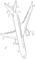
- Aircraft 100 has wing 102 and wing 104 attached to body 106. Aircraft 100 includes engine 108 attached to wing 102 and engine 110 attached to wing 104.
- Body 106 has tail section 112. Horizontal stabilizer 114, horizontal stabilizer 116, and vertical stabilizer 118 are attached to tail section 112 of body 106.
- Aircraft 100 is an example of an aircraft in which thermoplastic joining films can be used to form joints between composite parts.
- Aircraft 100 is an example of an aircraft in which carbon conductive layer can be used to heat a thermoplastic joining film to form a joint between composite parts.
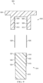
- Composite structure 200 can be joined together in manufacturing environment 202.
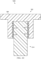
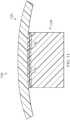
- Composite structure 200 comprises first composite component 204 joined to second composite component 206 by composite joint 208.
- First composite component 204 comprises first material 210.
- First material 210 can be either first thermoplastic material 212 or thermoset material 214. When first material 210 is first thermoplastic material 212, first thermoplastic material 212 has first melting temperature 216.
- Second composite component 206 comprises third material 218.
- Third material 218 can take the form of either third thermoplastic material 220 or thermoset material 222. When third material 218 is third thermoplastic material 220, third thermoplastic material 220 has third melting temperature 224.
- Composite joint 208 is formed between first composite component 204 and second composite component 206.
- Composite joint 208 includes a thermoplastic joining film that is melted at a lower temperature than that of both first melting temperature 216 and third melting temperature 224. By having a lower melting temperature than first melting temperature 216 and third melting temperature 224, consolidation is maintained in first material 210 and third material 218 while composite joint 208 is formed.
- thermoplastic joining film is consolidated to a respective composite component prior to being positioned for joining.
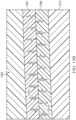
- thermoplastic joining film 226 is consolidated against plurality of layers 228 of first material 210.
- second thermoplastic joining film 242 is consolidated against plurality of layers 244 of third material 218.
- Thermoplastic joining film 226 can take any desirable form with second melting temperature 234 less than first melting temperature 216 and third melting temperature 224. Second melting temperature of second thermoplastic material 232 is configured such that first material 210 and third material 218 remain consolidated during joining of first composite component 204 and second composite component 206.
- Thermoplastic joining film 226 can have any desirable thickness. In some illustrative examples, the thickness of thermoplastic joining film 226 is in the range of about 25 ⁇ m (or 0.001") to about 508 ⁇ m (or 0.02").
- second thermoplastic material 232 is a polyaryletherketone 236. In some illustrative examples, second thermoplastic material 232 is a mixture 238 of two thermoplastic materials. In some illustrative examples, second thermoplastic material 232 is a mixture 238 of polyetherimide 240 and polyaryletherketone 236. In some illustrative examples, polyaryletherketone has second melting temperature 234 in a range of 260-350 degrees Celsius. Second melting temperature 234 can be used to co-consolidate thermoplastic joining film 226 with another thermoplastic material, such as first composite component 204. Second melting temperature 234 can be used to join thermoplastic joining film 226 to additional thermoplastic joining films, such as second thermoplastic joining film 242.
- mixture 238 of two thermoplastic materials has second melting temperature 234 in range of 260-350 degrees Celsius and a glass transition temperature in a range of 180-200 degrees Celsius.
- the glass transition temperature can be used to join thermoplastic joining film 226 to thermoset materials, such as when second composite component 206 is formed of thermoset material 222.
- thermoplastic joining film 226 is mixture 238 when at least one of first composite component 204 or second composite component 206 is formed of a thermoset material.
- thermoplastic joining film such as thermoplastic joining film 226, that will join a thermoset composite component and a thermoplastic composite component
- a thermoplastic joining film is a mixture of two thermoplastic materials.
- thermoplastic joining film such as thermoplastic joining film 226, that will join two thermoplastic composite components, is a single thermoplastic material with second melting temperature 234.
- composite joint 208 is formed by a single layer of thermoplastic joining film, such as thermoplastic joining film 226 or second thermoplastic joining film 242. In some illustrative examples, composite joint 208 is formed of multiple layers of thermoplastic joining film. In some illustrative examples, second thermoplastic joining film 242 is consolidated against plurality of layers 244 of third thermoplastic material 220 to form second surface 243 of second composite component 206. Second thermoplastic joining film 242 can take any desirable form with second melting temperature 234 less than first melting temperature 216 and third melting temperature 224. In some illustrative examples, second thermoplastic joining film 242 is mixture 238 when at least one of first composite component 204 or second composite component 206 is formed of a thermoset material.
- composite joint 208 comprises first composite component 204 formed of one of thermoset material 214 or first thermoplastic material 212; second composite component 206 formed of thermoset material 222 or third thermoplastic material 220; thermoplastic joining film 226 formed of second thermoplastic material 232 between first composite component 204 and second composite component 206; and carbon conductive layer 256 in thermoplastic joining film 226.
- Second thermoplastic material 232 is different from thermoset material 214, first thermoplastic material 212, and third thermoplastic material 220.
- second thermoplastic material 232 has second melting temperature 234 lower than first melting temperature 216 of first thermoplastic material 212 when first composite component 204 is formed of first thermoplastic material 212.
- Second melting temperature 234 is lower third melting temperature 224 of third thermoplastic material 220 when second composite component 206 is formed of third thermoplastic material 220.
- first composite component 204 is a stiffener and second composite component 206 is a skin.
- first composite component 204 is a bracket and second composite component 206 is a stiffener.
- thermoplastic joining film 226 has been consolidated into one of first composite component 204 or second composite component 206.
- second thermoplastic joining film 242 is in contact with the thermoplastic joining film.
- second thermoplastic joining film 242 is consolidated into the other of first composite component 204 or second composite component 206.
- composite joint 208 comprises first composite component 204, second composite component 206, and carbon conductive layer 256.
- First composite component 204 comprises plurality of layers 228 of first thermoplastic material 212 and first surface 230 comprising second thermoplastic material 232, second thermoplastic material 232 having second melting temperature 234 lower than first melting temperature 216 of first thermoplastic material 212.
- Second composite component 206 comprising plurality of layers 244 of third thermoplastic material 220 and second surface 243 formed of second thermoplastic material 232, second thermoplastic material 232 having second melting temperature 234 lower than third melting temperature 224 of third thermoplastic material 220.
- Carbon conductive layer 256 is positioned one of between first surface 230 and second surface 243, within first surface 230, or within second surface 243.
- first thermoplastic material 212 is one of polyetherketoneketone (PEKK), polyetheretherketone (PEEK), or a blend of polyetheretherketone (PEEK) and polyetherketoneketone (PEKK).
- third thermoplastic material 220 is one of polyetherketoneketone (PEKK), polyetheretherketone (PEEK), or a blend of polyetheretherketone (PEEK) and polyetherketoneketone (PEKK).
- Carbon conductive layer 256 is present in composite structure 200 to melt second thermoplastic material 232 to join first composite component 204 and second composite component 206.
- carbon conductive layer 256 is a one of mesh 262, coil 260, or unidirectional tape 264.
- carbon fiber 258 in carbon conductive layer 256 generates heat to melt second thermoplastic material 232.
- carbon conductive layer 256 has thickness 266 in a range of 127 ⁇ m (or 0.005") to 508 ⁇ m (0.02").
- Carbon conductive layer 256 produces heat when current 268 is applied to carbon conductive layer 256.
- heat 272 can also be applied by oven 270.
- carbon conductive layer 256 can be optional.
- Control system 269 is present to control application of current 268.
- current 268 is controlled based on a feedback control loop.
- Temperature sensor 271 is present to monitor temperature 273 of thermoplastic joining film 226.
- Control system 269 is configured to control current 268 applied to carbon conductive layer 256 based on temperature 273 of thermoplastic joining film 226.
- composite joint 208 comprises first composite component 204 comprising first thermoplastic material 212 having first melting temperature 216; second composite component 206 comprising thermoset material 214; and a thermoplastic joining film between the first composite component 204 and second composite component 206.
- the thermoplastic joining film at least one of thermoplastic joining film 226 or second thermoplastic material 232, comprises a mixture of two thermoplastic materials having second melting temperature 234 lower than first melting temperature 216.
- thermoplastic joining film 226 is in contact with first composite component 204, and composite joint 200 further comprises second thermoplastic joining film 242 and epoxy film adhesive 274. Second thermoplastic joining film 242 is in contact with second composite component 206. Second thermoplastic joining film 242 is formed of mixture 238 of the two thermoplastic materials. Epoxy film adhesive 274 is positioned between thermoplastic joining film 226 and second thermoplastic joining film 242.
- mixture 238 of the two thermoplastic materials has diffused into epoxy film adhesive 274.
- epoxy film adhesive 274 has diffused into thermoplastic joining film 226 and second thermoplastic joining film 242.
- second thermoplastic joining film 242 was consolidated to second composite component 206 to form second surface 243 of second composite component 206.
- thermoplastic joining film 226 is in contact with first composite component 204, and composite joint 200 further comprises epoxy film adhesive 274 positioned between thermoplastic joining film 226 and second composite component 206.
- thermoplastic joining film 226 comprises mixture 238 of the two thermoplastic materials.
- epoxy film adhesive 274 has diffused into thermoplastic joining film 226 and mixture 238 of the two thermoplastic materials has diffused into epoxy film adhesive 274.
- the two thermoplastic materials comprise polyetherimide 240 and a polyaryletherketone 236.
- mixture 238 of the two thermoplastic materials has diffused into second composite component 206.
- thermoplastic joining film was consolidated to first composite component 204 to form surface 230 of first composite component 204.
- a composite component can be joined to multiple other components.
- first composite component 204 can be joined to second composite component 206 and another composite component.
- Thermoplastic joining film 226 is positioned to join first composite component 204 to second composite component 206.
- Thermoplastic joining film 226 forms surface 230.
- first composite component 204 further comprises additional thermoplastic joining film 276.
- Additional thermoplastic joining film 276 forms additional surface 278 to join first composite component 204 to an additional composite component.
- Additional thermoplastic joining film 276 is formed of material 280.
- Additional thermoplastic joining film 276 has respective melting temperature 282 lower than first melting temperature 216.
- material 280 is mixture 284 of two thermoplastic materials.
- Additional thermoplastic joining film 276 can include at least one of polyetherimide 288 or polyaryletherketone 286.
- thermoplastic joining film 226 and additional thermoplastic joining film 276 are formed of different thermoplastic materials.
- one of thermoplastic joining film 226 and additional thermoplastic joining film 276 is configured to join first composite component 204 to a thermoset material while the other of thermoplastic joining film 226 and additional thermoplastic joining film 276 is configured to join first composite component 204 to a thermoplastic material.
- manufacturing environment 202 in Figure 2 is not meant to imply physical or architectural limitations to the manner in which an illustrative example may be implemented.
- Other components in addition to or in place of the ones illustrated may be used. Some components may be unnecessary.
- the blocks are presented to illustrate some functional components. One or more of these blocks may be combined, divided, or combined and divided into different blocks when implemented in an illustrative example.
- carbon conductive layer 256 can be formed of a carbon preform of any desirable construction.
- an additional composite component (not depicted) can be joined to first composite component by additional thermoplastic joining film 276.
- first composite component 302 and second composite component 304 are visible.
- First composite component 302 is a physical implementation of first composite component 204 of Figure 2 .
- Second composite component 304 is a physical implementation of second composite component 206 of Figure 2 .
- First composite component 302 takes the form of hat-shaped stiffener 301 while second composite component 304 takes the form of skin 303.
- First composite component 302 comprises a plurality of layers of first thermoplastic material 306 and portions of a second thermoplastic material.
- First thermoplastic material 306 has a first melting temperature.
- first thermoplastic material 306 is one of polyetherketoneketone (PEKK), polyetheretherketone (PEEK), or a blend of polyetheretherketone (PEEK) and polyetherketoneketone (PEKK).
- first thermoplastic material 306 is polyaryletherketone.
- the portions of second thermoplastic material include second thermoplastic material 308 and second thermoplastic material 310 forming legs of hat-shaped stiffener 301.
- Second thermoplastic material 308 and second thermoplastic material 310 have a second melting temperature. The second melting temperature is lower than the first melting temperature of first thermoplastic material 306.
- Thermoplastic joining film 309 is formed by second thermoplastic material 308.
- Thermoplastic joining film 311 is formed by second thermoplastic material 310.
- Thermoplastic joining film 309 and thermoplastic joining film 311 can be used to form a joint between first composite component 302 and second composite component 304.
- Second thermoplastic material 308 forms surface 312 of first composite component 302.
- Surface 312 is a surface of a first leg of hat-shaped stiffener 301.
- Second thermoplastic material 310 forms surface 314 of first composite component 302.
- Surface 314 is a surface of a second leg of hat-shaped stiffener 301.
- second thermoplastic material 308 was consolidated with first thermoplastic material 306.
- second thermoplastic material 310 was consolidated with first thermoplastic material 306.
- the consolidation step can be performed by any desirable tooling or method. In some illustrative examples, consolidation can be performed using at least one of continuous compression molding (CCM), stamp forming, or an autoclave. The consolidation is performed at a temperature higher than the second melting temperature of second thermoplastic material 308 and second thermoplastic material 310.
- CCM continuous compression molding
- Second composite component 304 comprises third thermoplastic material 316 and second thermoplastic material 318.
- Second thermoplastic material 318 has the second melting temperature. The second melting temperature is lower than the third melting temperature of third thermoplastic material 316.
- Thermoplastic joining film 319 is formed by second thermoplastic material 318.
- Surface 320 of second composite component 304 is formed by consolidating second thermoplastic material 318 and third thermoplastic material 316.
- the consolidation step can be performed by any desirable tooling or method. In some illustrative examples, consolidation can be performed using at least one of CCM, stamp forming, or an autoclave. The consolidation is performed at a temperature higher than the second melting temperature of second thermoplastic material 318.
- a respective carbon conductive layer is positioned between each thermoplastic joining film of first composite component 302 and thermoplastic joining film 319 of second composite component 304.
- a carbon conductive layer can be positioned between thermoplastic joining film 309 and thermoplastic joining film 319.
- a carbon conductive layer can be positioned between thermoplastic joining film 311 and thermoplastic joining film 319.
- a carbon conductive layer can be used to heat the second thermoplastic material to the second melting temperature to join first composite component 302 and second composite component 304 without melting first thermoplastic material 306 or third thermoplastic material 316.
- first composite component 402 and second composite component 404 are visible.
- First composite component 402 is a physical implementation of first composite component 204 of Figure 2 .
- Second composite component 404 is a physical implementation of second composite component 206 of Figure 2 .
- First composite component 402 takes the form of L-shaped stiffener 406 while second composite component 404 takes the form of skin 408.
- First composite component 402 comprises a plurality of layers of first thermoplastic material 410 and second thermoplastic material 412.
- First thermoplastic material 410 has a first melting temperature.
- first thermoplastic material 410 is one of polyetherketoneketone (PEKK), polyetheretherketone (PEEK), or a blend of polyetheretherketone (PEEK) and polyetherketoneketone (PEKK).
- first thermoplastic material 401 is one of polyaryletherketone (PEKK), polyetheretherketone (PEEK), or a blend of polyetheretherketone (PEEK) and polyetherketoneketone (PEKK).
- Second thermoplastic material 412 has a second melting temperature. The second melting temperature is lower than the first melting temperature of first thermoplastic material 410.
- Thermoplastic joining film 413 is formed by second thermoplastic material 412.
- Thermoplastic joining film 413 can be used to form a joint between first composite component 402 and second composite component 404.
- Second thermoplastic material 412 forms surface 414 of first composite component 402. To form surface 414, second thermoplastic material 412 was consolidated with first thermoplastic material 410. In some illustrative examples, second thermoplastic material 412 is a single thermoplastic material.
- Second composite component 404 comprises third thermoplastic material 416 and second thermoplastic material 418.
- Second thermoplastic material 418 has the second melting temperature. The second melting temperature is lower than the third melting temperature of third thermoplastic material 416.
- Thermoplastic joining film 419 is formed by second thermoplastic material 418.
- Surface 420 of second composite component 404 is formed by consolidating second thermoplastic material 418 and third thermoplastic material 416.
- carbon conductive layer 422 is positioned between thermoplastic joining film 413 of first composite component 402 and thermoplastic joining film 419 of second composite component 404.
- carbon conductive layer 422 is positioned between surface 414 and surface 420.
- Carbon conductive layer 422 can be used to heat second thermoplastic material 412 and second thermoplastic material 418 to the second melting temperature to join first composite component 402 and second composite component 404 without melting first thermoplastic material 410 or third thermoplastic material 416.
- Carbon conductive layer 422 takes any desirable form.
- carbon conductive layer 422 takes the form of at least one of a coil, a mesh, or a unidirectional tape.
- View 500 is a view of joint 502 connecting first composite component 402 and second composite component 404.
- carbon conductive layer 422 has heated second thermoplastic material 412 and second thermoplastic material 418 to the second melting temperature to form joint 502.
- consolidation is performed to form joint 502.
- the consolidation is performed at a temperature in the range of 260 degrees Celsius to 350 degrees Celsius.
- the heat is provided by carbon conductive layer 422.
- the heat is provided by a combination of carbon conductive layer 422 and an oven.
- FIG. 6 an illustration of an isometric view of composite stiffeners joined to a composite skin using conductive layers is depicted in accordance with an illustrative example.
- plurality of stiffeners 602 and skin 604 are present.
- Skin 604 is a physical implementation of second composite component 206 of Figure 2 .
- Skin 604 comprises surface 606 formed of thermoplastic joining film 607.
- Each of plurality of stiffeners 602 can be an implementation of first composite component 204 of Figure 2 .
- skin 604 and each of plurality of stiffeners 602 is formed of a respective thermoplastic materials.
- Plurality of stiffeners 602 comprises stiffener 608, stiffener 610, stiffener 612, stiffener 614, and stiffener 616.
- Each stiffener of plurality of stiffeners 602 comprises a second thermoplastic material.
- carbon conductive layer 618 is between thermoplastic joining film 607 and second thermoplastic material 619 of stiffener 616.
- Carbon conductive layer 618 is configured to heat thermoplastic joining film 607 and second thermoplastic material 619 to join stiffener 616 to skin 604.
- Carbon conductive layer 620 is between thermoplastic joining film 607 and second thermoplastic material 621 of stiffener 614.
- Carbon conductive layer 620 is configured to heat thermoplastic joining film 607 and second thermoplastic material 621 to join stiffener 614 to skin 604.
- Carbon conductive layer 622 is between thermoplastic joining film 607 and second thermoplastic material 623 of stiffener 612. Carbon conductive layer 622 is configured to heat thermoplastic joining film 607 and second thermoplastic material 623 to join stiffener 612 to skin 604.
- Carbon conductive layer 624 is between thermoplastic joining film 607 and second thermoplastic material 625 of stiffener 610. Carbon conductive layer 624 is configured to heat thermoplastic joining film 607 and second thermoplastic material 625 to join stiffener 610 to skin 604.
- Carbon conductive layer 626 is between thermoplastic joining film 607 and second thermoplastic material 627 of stiffener 608. Carbon conductive layer 626 is configured to heat thermoplastic joining film 607 and second thermoplastic material 627 to join stiffener 608 to skin 604.
- first composite component 702 and second composite component 710 are visible.
- First composite component 702 is a physical implementation of first composite component 204 of Figure 2 .
- Second composite component 710 is a physical implementation of second composite component 206 of
- First composite component 702 takes the form of a bracket having a tapered shape.
- First composite component 702 comprises a plurality of layers of first thermoplastic material 704 and portions of a second thermoplastic material.
- First thermoplastic material 704 has a first melting temperature.
- the portions of second thermoplastic material include second thermoplastic material 706 and second thermoplastic material 708.
- Second thermoplastic material 706 and second thermoplastic material 708 have a second melting temperature.
- the second melting temperature is lower than the first melting temperature of first thermoplastic material 704.
- first thermoplastic material 704 is one of polyetherketoneketone(PEKK), polyetheretherketone (PEEK), or a blend of polyetheretherketone (PEEK) and polyetherketoneketone (PEKK).
- first thermoplastic material 704 is polyaryletherketone.
- Thermoplastic joining film 707 is formed by second thermoplastic material 706.
- Thermoplastic joining film 709 is formed by second thermoplastic material 708.
- Thermoplastic joining film 707 and thermoplastic joining film 709 can be used to form a joint between first composite component 702 and second composite component 710.
- Second thermoplastic material 706 forms surface 705 of first composite component 702.
- Second thermoplastic material 708 forms surface 711 of first composite component 702.
- surface 705 and surface 711 are tapered.
- second thermoplastic material 706 was consolidated with first thermoplastic material 704.
- second thermoplastic material 708 was consolidated with first thermoplastic material 704.
- the consolidation step can be performed by any desirable tooling or method. In some illustrative examples, consolidation can be performed using at least one of CCM, stamp forming, or an autoclave. The consolidation is performed at a temperature higher than the second melting temperature of second thermoplastic material 706 and second thermoplastic material 708.
- Second composite component 710 comprises third thermoplastic material 712 and a second thermoplastic material.
- second composite component 710 comprises second thermoplastic material 714 and second thermoplastic material 716.
- Second thermoplastic material 714 and second thermoplastic material 716 have the second melting temperature. The second melting temperature is lower than the third melting temperature of third thermoplastic material 712.
- Thermoplastic joining film 713 is formed by second thermoplastic material 714.
- Surface 717 of second composite component 710 is formed by consolidating second thermoplastic material 714 and third thermoplastic material 712.
- surface 717 and surface 719 are tapered.
- Thermoplastic joining film 715 is formed by second thermoplastic material 716.
- Surface 719 of second composite component 710 is formed by consolidating second thermoplastic material 716 and third thermoplastic material 712.
- the consolidation step can be performed by any desirable tooling or method. In some illustrative examples, consolidation can be performed using at least one of CCM, stamp forming, or an autoclave. The consolidation is performed at a temperature higher than the second melting temperature of second thermoplastic material 714 and second thermoplastic material 716.
- a respective carbon conductive layer is positioned between each thermoplastic joining film of first composite component 702 and a respective thermoplastic joining film of second composite component 710.
- carbon conductive layer 718 can be positioned between thermoplastic joining film 707 and thermoplastic joining film 715.
- Carbon conductive layer 720 can be positioned between thermoplastic joining film 709 and thermoplastic joining film 713.
- Each of carbon conductive layer 718 and carbon conductive layer 720 can be used to heat respective portions of the second thermoplastic material to the second melting temperature to join first composite component 702 and second composite component 710 without melting first thermoplastic material 704 or third thermoplastic material 712.
- carbon conductive layer 718 can be used to heat second thermoplastic material 716 and second thermoplastic material 706.
- carbon conductive layer 720 can be used to heat second thermoplastic material 708 and second thermoplastic material 714.
- thermoplastic joining film 707, thermoplastic joining film 709, thermoplastic joining film 713, and thermoplastic joining film 715 are described as being formed of the same second thermoplastic material.
- at least one of thermoplastic joining film 707, thermoplastic joining film 709, thermoplastic joining film 713, or thermoplastic joining film 715 can be formed of a different type of thermoplastic material.
- thermoplastic joining film 707, thermoplastic joining film 709, thermoplastic joining film 713, or thermoplastic joining film 715 can be formed of any desirable type of thermoplastic material configured to be compatible with first thermoplastic material 704 and third thermoplastic material 712.
- thermoplastic joining film 707, thermoplastic joining film 709, thermoplastic joining film 713, or thermoplastic joining film 715 can be formed of any desirable type of thermoplastic material with a melting temperature lower than first melting temperature of first thermoplastic material 704 and third melting temperature of third thermoplastic material 712.
- thermoplastic bracket/clip first composite component 702, to the thermoplastic crossmember, second composite component 710.
- Figures 9-10 likewise depict joining of a thermoplastic bracket/clip, first composite component 902, to the thermoplastic crossmember, second composite component 914.
- both the bracket and crossmember will have the low melt PAEK film co-consolidated on the mating area of those two structures.
- the processing temperature for consolidating the thermoplastic joining film to the respective composite component will take place at 375 C +/- 10 C.
- the low melt PAEK film instead of having separate carbon conductive layers, the low melt PAEK film will be impregnated with a scrim to help maintain film layer thickness.
- the heating can follow a conductive heating approach. The heating can also result from having electrical elements at the bond line.
- Bracket to crossmember mating configurations Two types are depicted in these illustrative examples.
- One type is to have a tapering structure, as depicted in Figures 7-8 . This taper will ensure that there is no gap between the bracket, first composite component 702, and the crossmember, second composite component 710 as any excess joining film will be squeezed out from that cavity as pressure and temperature are applied.
- View 800 is a view of joint 802 and joint 804 connecting first composite component 702 and second composite component 710.
- Joint 802 and joint 804 are formed through consolidation of first composite component 702 and second composite component 710.
- the consolidation of first composite component 702 and second composite component 710 comprises elevated temperature and pressure.
- carbon conductive layer 718 has been used to heat second thermoplastic material 716 and second thermoplastic material 706 to the second melting temperature
- carbon conductive layer 720 has been used to heat second thermoplastic material 708 and second thermoplastic material 714 to the second melting temperature to form joint 802 and joint 804.
- heat is applied through carbon conductive layer 718 and carbon conductive layer 720 only.
- additional heat can be supplied by conductive heating.
- Pressure for the consolidation can be provided by pressing second composite component 710 into first composite component 702.
- first composite component 902 and second composite component 914 are visible.
- First composite component 902 is a physical implementation of first composite component 204 of Figure 2 .
- Second composite component 914 is a physical implementation of second composite component 206 of Figure 2 .
- First composite component 902 takes the form of a bracket.
- First composite component 902 comprises a plurality of layers of first thermoplastic material 904 and portions of a second thermoplastic material.
- First thermoplastic material 904 has a first melting temperature.
- first thermoplastic material 904 is one of polyetherketoneketone (PEKK), polyetheretherketone (PEEK), or a blend of polyetheretherketone (PEEK) and polyetherketoneketone (PEKK).
- first thermoplastic material 904 is polyaryletherketone.
- the portions of second thermoplastic material include second thermoplastic material 906 and second thermoplastic material 908.
- Second thermoplastic material 906 and second thermoplastic material 908 have a second melting temperature.
- the second melting temperature is lower than the first melting temperature of first thermoplastic material 904.
- Thermoplastic joining film 909 is formed by second thermoplastic material 908.
- Thermoplastic joining film 907 is formed by second thermoplastic material 906.
- Thermoplastic joining film 909 and thermoplastic joining film 907 can be used to form a joint between first composite component 902 and second composite component 914.
- Second thermoplastic material 906 forms surface 910 of first composite component 902.
- Second thermoplastic material 908 forms surface 912 of first composite component 902.
- surface 910 and surface 912 are planar instead of tapered.
- second thermoplastic material 906 was consolidated with first thermoplastic material 904.
- second thermoplastic material 908 was consolidated with first thermoplastic material 904.
- the consolidation step can be performed by any desirable tooling or method. In some illustrative examples, consolidation can be performed using at least one of CCM, stamp forming, or an autoclave. The consolidation is performed at a temperature higher than the second melting temperature of second thermoplastic material 906 and second thermoplastic material 908.
- Second composite component 914 comprises third thermoplastic material 916 and a second thermoplastic material.
- second composite component comprises second thermoplastic material 918 and second thermoplastic material 920 .
- Second thermoplastic material 918 and second thermoplastic material 920 have the second melting temperature. The second melting temperature is lower than the third melting temperature of third thermoplastic material 916 .
- Thermoplastic joining film 922 is formed by second thermoplastic material 918 .
- Surface 919 of second composite component 914 is formed by consolidating second thermoplastic material 918 and third thermoplastic material 916 .
- Surface 919 and surface 924 are parallel.
- Thermoplastic joining film 921 is formed by second thermoplastic material 920 .
- Surface 924 of second composite component 914 is formed by consolidating second thermoplastic material 920 and third thermoplastic material 916 .
- the consolidation step can be performed by any desirable tooling or method. In some illustrative examples, consolidation can be performed using at least one of CCM, stamp forming, or an autoclave. The consolidation is performed at a temperature higher than the second melting temperature of second thermoplastic material 918 and second thermoplastic material 920 .
- a respective carbon conductive layer is positioned between each thermoplastic joining film of first composite component 902 and a respective thermoplastic joining film of second composite component 914 .
- carbon conductive layer 926 can be positioned between thermoplastic joining film 922 and Thermoplastic joining film 909 .
- Carbon conductive layer 928 can be positioned between thermoplastic joining film 921 and thermoplastic joining film 907.
- Each of carbon conductive layer 928 and carbon conductive layer 926 can be used to heat respective portions of the second thermoplastic material to the second melting temperature to join first composite component 902 and second composite component 914 without melting first thermoplastic material 904 or third thermoplastic material 916.
- carbon conductive layer 928 can be used to heat second thermoplastic material 920 and second thermoplastic material 906.
- carbon conductive layer 926 can be used to heat second thermoplastic material 908 and second thermoplastic material 918.
- each of thermoplastic joining film 907, thermoplastic joining film 909, thermoplastic joining film 922, and Thermoplastic joining film 921 are described as being formed of the same second thermoplastic material.
- at least one of thermoplastic joining film 907, thermoplastic joining film 909, thermoplastic joining film 922, or thermoplastic joining film 921 can be formed of a different type of thermoplastic material.
- Each of thermoplastic joining film 909, thermoplastic joining film 909, thermoplastic joining film 922, or Thermoplastic joining film 921 can be formed of any desirable type of thermoplastic material configured to be compatible with first thermoplastic material 904 and third thermoplastic material 916.
- thermoplastic joining film 907, thermoplastic joining film 909, thermoplastic joining film 922, or thermoplastic joining film 921 can be formed of any desirable type of thermoplastic material with a melting temperature lower than first melting temperature of first thermoplastic material 904 and third melting temperature of third thermoplastic material 916.
- This configuration provides a non-tapered joint structure.
- This non-tapered joint achieves joining film squeeze out from excess film material to ensure the all the gaps are closed.
- View 1000 is a view of joint 1002 and joint 1004 connecting first composite component 902 and second composite component 914.
- Joint 1002 and joint 1004 are formed through consolidation of first composite component 902 and second composite component 914.
- the consolidation of first composite component 902 and second composite component 914 comprises elevated temperature and pressure.
- carbon conductive layer 926 has been used to heat second thermoplastic material 908 and second thermoplastic material 918 to the second melting temperature and carbon conductive layer 928 has been used to heat second thermoplastic material 920 and second thermoplastic material 906 to the second melting temperature to form joint 1002 and joint 1004.
- heat is applied through carbon conductive layer 926 and carbon conductive layer 928 only.
- additional heat can be supplied by conductive heating.
- Pressure for the consolidation can be provided by an interference fit between second composite component 914 into first composite component 902.
- first composite component 1102 is joined to second composite component 1104 by thermoplastic joining film 1106 having carbon conductive layer 1108.
- first composite component 1102 is formed of a thermoset material.
- second composite component 1104 is formed of a thermoplastic material.
- Thermoplastic joining film 1106 is formed of a material having a second melting temperature lower than a first melting temperature of second composite component 1104.
- thermoplastic joining film 1106 can be applied between first composite component 1102 and second composite component 1104 in any desirable fashion.
- thermoplastic joining film 1106 is consolidated onto first composite component 1102 before joining.
- thermoplastic joining film 1106 is consolidated onto second composite component 1104 before joining.
- the illustrative examples enable the efficient joining of epoxy thermoset skins (from either fuselage or wing structures) to PAEK thermoplastic substructure in the form of brackets and clips.
- This joint makes use a PAEK to epoxy joining mechanism utilizing a PAEK/PEI blend tie layer. Due to the softening mechanism involved with this tie layer, the proposed structure is configured to ensure proper mating between the constituent structures.
- thermoplastic joining film allows for polymer chain entanglement to occur between a thermoplastic and thermoset epoxy resins.
- An epoxy skin can be joined to a thermoplastic bracket or clip using a PAEK/PEI thermoplastic joining film.
- a thermoset skin can be either prepreg or resin infused, such as liquid molded or B-staged resin.
- the thermoset skin can be either co-bonded onto the thermoplastic bracket or it can be pre-cured and secondarily bonded onto the thermoplastic bracket by using an epoxy film adhesive. This joining can take place at the usual temperatures used to cure epoxy resins (350 F +/- 10 F).
- thermoplastic bracket can be stamp formed or compression molded with a layer of PAEK/PEI film on the surface.
- PAEK/PEI thermoplastic joining film for co-bonding or secondarily bonding to the epoxy skin with epoxy film adhesive, no aggressive surface prep procedure on the thermoplastic bracket part will be performed. Reducing or eliminating aggressive surface prep procedures will reduce the cost and time of joining thermoset and thermoplastic components.
- thermoplastic joining film 1206 is formed of a mixture of two different thermoplastic materials.
- thermoplastic joining film 1206 is formed of a mixture of polyetherimide and a polyaryletherketone.
- Thermoplastic joining film 1206 has a second melting temperature lower than a first melting temperature of first thermoplastic material 1212 forming second composite component 1204.
- thermoplastic joining film 1206 has a glass transition temperature in the range of 140-220 degrees Celsius.
- joining can be performed at a temperature in the range of 180-200 degrees Celsius to join first composite component 1202 and second composite component 1204.
- first thermoplastic material 1212 is one of polyetherketoneketone (PEKK), polyetheretherketone (PEEK), or a blend of polyetheretherketone (PEEK) and polyetherketoneketone (PEKK).
- first thermoplastic material 1212 is one of polyaryletherketone (PEKK), polyetheretherketone (PEEK), or a blend of polyetheretherketone (PEEK) and polyetherketoneketone (PEKK).
- PEKK polyaryletherketone
- PEEK polyetheretherketone
- PEKK polyetherketoneketone
- thermoplastic joining film 1206 has been consolidated onto second composite component 1204.
- thermoset material 1214 of first composite component 1202 has diffused into thermoplastic joining film 1206.
- thermoplastic material 1216 of thermoplastic joining film 1206 has diffused into first composite component 1202.
- first composite component 1202 is provided in an uncured epoxy composite material, such as a liquid molded or B-staged resin. The epoxy composite material of first composite component 1202 is cured to form the diffusions.
- Thermoplastic joining film 1206 joins first composite component 1202 and second composite component 1204 at joint 1207.
- first composite component 1202 is a thermoset material.
- a carbon conductive layer (not depicted) is present in joint 1207 to heat thermoplastic joining film 1206 for forming joint 1207.
- second composite component 1204 can be joined to another composite component.
- second thermoplastic material 1208 forms thermoplastic joining film 1209 and second thermoplastic material 1210 forms thermoplastic joining film 1211.
- second thermoplastic material 1208 and second thermoplastic material 1210 are the same as thermoplastic joining film 1206.
- second thermoplastic material 1208 and second thermoplastic material 1210 are different from thermoplastic joining film 1206.
- second thermoplastic material 1208 and second thermoplastic material 1210 comprises a polyaryletherketone.
- the polyaryletherketone has a melting temperature in the range of 260-350 degrees Celsius.
- second composite component 1204 can be joined to a third composite component at thermoplastic joining film 1211 and thermoplastic joining film 1209. In some illustrative examples, second composite component 1204 is joined to a third composite component similar to second composite component 710 of Figures 7 and 8 . In some illustrative examples, thermoplastic joining film 1211 and thermoplastic joining film 1209 can form joints like joint 802 and joint 804 of Figure 8 .
- first composite component 1302 is joined to second composite component 1304 by thermoplastic joining film 1306 and epoxy film adhesive 1307.
- first composite component 1302 is a thermoset material.
- Thermoplastic joining film 1306 and epoxy film adhesive 1307 form joint 1313 between first composite component 1302 and second composite component 1304.
- a carbon conductive layer (not depicted) is present in joint 1313 to heat thermoplastic joining film 1306 for forming joint 1313.
- Thermoplastic joining film 1306 has a second melting temperature lower than a first melting temperature of first thermoplastic material 1312 forming second composite component 1304.
- thermoplastic joining film 1306 has a glass transition temperature in the range of 140-200 degrees Celsius. In some of these illustrative examples, joining can be performed at a temperature in the range of 140-200 degrees Celsius to join first composite component 1302 and second composite component 1304.
- first thermoplastic material 1312 is one of polyetherketoneketone (PEKK), polyetheretherketone (PEEK), or a blend of polyetheretherketone (PEEK) and polyetherketoneketone (PEKK).
- first thermoplastic material 1312 is polyaryletherketone. In this illustrative example, thermoplastic joining film 1306 has been consolidated onto second composite component 1304.
- epoxy film adhesive 1307 has diffused 1314 into thermoplastic joining film 1306.
- thermoplastic material 1316 of thermoplastic joining film 1306 has diffused into epoxy film adhesive 1307.
- thermoplastic joining film 1306 is formed of a mixture of two different thermoplastic materials. In some illustrative examples, thermoplastic joining film 1306 is formed of a mixture of polyetherimide and a polyaryletherketone.
- second composite component 1304 can be joined to another composite component.
- second thermoplastic material 1308 forms thermoplastic joining film 1309 and second thermoplastic material 1310 forms thermoplastic joining film 1311.
- second thermoplastic material 1308 and second thermoplastic material 1310 are the same as thermoplastic joining film 1306.
- second thermoplastic material 1308 and second thermoplastic material 1310 are different from thermoplastic joining film 1306.
- second thermoplastic material 1308 and second thermoplastic material 1310 comprises a polyaryletherketone.
- the polyaryletherketone has a melting temperature in the range of 260-350 degrees Celsius.
- second composite component 1304 can be joined to a third composite component at thermoplastic joining film 1311 and thermoplastic joining film 1309. In some illustrative examples, second composite component 1304 is joined to a third composite component similar to second composite component 710 of Figures 7 and 8 . In some illustrative examples, thermoplastic joining film 1311 and thermoplastic joining film 1309 can form joints like joint 802 and joint 804 of Figure 8 .
- first composite component 1402 is joined to second composite component 1404 by thermoplastic joining film 1405, thermoplastic joining film 1406, and one of either epoxy film adhesive or thermoplastic joining film 1407.
- Layer 1407 can take the form of either epoxy film adhesive or a thermoplastic joining film of a different composition than thermoplastic joining film 1405, thermoplastic joining film 1406.
- thermoplastic joining film 1405 and thermoplastic joining film 1406 are a mixture of two different thermoplastic materials while thermoplastic joining film 1407 comprises a single thermoplastic material.
- first composite component 1402 is a thermoset material.
- Joining film 1406, thermoplastic joining film 1405, and one of either epoxy film adhesive or thermoplastic joining film 1407 form joint 1403 between first composite component 1402 and second composite component 1404.
- thermoplastic joining film 1406 forms surface 1422 of second composite component 1404.
- thermoplastic joining film 1405 forms surface 1420 of first composite component 1402.
- a carbon conductive layer (not depicted) is present in joint 1403 to heat thermoplastic joining film 1406 and thermoplastic joining film 1405 for forming joint 1403. When present in joint 1403, the carbon conductive layer can be present between thermoplastic joining film 1405 and thermoplastic joining film 1406, within thermoplastic joining film 1405, or within thermoplastic joining film 1406.
- thermoplastic joining film 1406 and thermoplastic joining film 1405 have a second melting temperature lower than a first melting temperature of first thermoplastic material 1412 forming second composite component 1404.
- thermoplastic joining film 1406 has a glass transition temperature in the range of 140-220 degrees Celsius.
- joining can be performed at a temperature in the range of 140-220 degrees Celsius to join first composite component 1402 and second composite component 1404.
- first thermoplastic material 1412 is one of polyetherketoneketone (PEKK), polyetheretherketone (PEEK), or a blend of polyetheretherketone (PEEK) and polyetherketoneketone (PEKK).
- first thermoplastic material 1412 is polyaryletherketone.
- thermoplastic joining film 1406 has been consolidated onto second composite component 1404.
- thermoplastic joining film 1405 has been consolidated onto first composite component 1402.
- thermoplastic joining film 1407 As can be seen in the callout, one of either epoxy film adhesive or thermoplastic joining film 1407 has diffused 1414 into thermoplastic joining film 1406. One of either epoxy film adhesive or thermoplastic joining film 1407 has diffused 1418 into thermoplastic joining film 1405. As can be seen in the callout, thermoplastic material 1416 of thermoplastic joining film 1406 and thermoplastic joining film 1405 has diffused into one of either epoxy film adhesive or thermoplastic joining film 1407. When 1407 is a thermoplastic joining film, thermoplastic joining film 1407 diffuses into both thermoplastic joining film 1406 and thermoplastic joining film 1405. When 1407 is an epoxy film adhesive, epoxy film adhesive 1407 diffuses into both thermoplastic joining film 1406 and thermoplastic joining film 1405..
- thermoplastic joining film 1406 and thermoplastic joining film 1405 is formed of a mixture of two different thermoplastic materials. In some illustrative examples, at least one of thermoplastic joining film 1406 and thermoplastic joining film 1405 is formed of a mixture of polyetherimide and a polyaryletherketone.
- second composite component 1404 can be joined to another composite component.
- second thermoplastic material 1408 forms thermoplastic joining film 1409 and second thermoplastic material 1410 forms thermoplastic joining film 1411.
- second thermoplastic material 1408 and second thermoplastic material 1410 are the same as thermoplastic joining film 1406.
- second thermoplastic material 1408 and second thermoplastic material 1410 are different from thermoplastic joining film 1406.
- second thermoplastic material 1408 and second thermoplastic material 1410 comprises a polyaryletherketone.
- the polyaryletherketone has a melting temperature in the range of 260-350 degrees Celsius.
- second composite component 1404 can be joined to a third composite component at thermoplastic joining film 1411 and thermoplastic joining film 1409. In some illustrative examples, second composite component 1404 is joined to a third composite component similar to second composite component 710 of Figures 7 and 8 . In some illustrative examples, thermoplastic joining film 1411 and thermoplastic joining film 1409 can form joints like joint 802 and joint 804 of Figure 8 .
- Method 1500 can be performed in manufacturing environment 202 to form composite joint 200.
- Method 1500 can be performed on first composite component 302 and second composite component 304 of Figure 3 .
- Method 1500 can be performed on first composite component 402 and second composite component 404 of Figures 4 and 5 .
- Method 1500 can be performed on plurality of stiffeners 602 and skin 604 of Figure 6 .
- Method 1500 can be performed on first composite component 702 and second composite component 710 of Figures 7 and 8 .
- Method 1500 can be performed on first composite component 902 and second composite component 914 of Figures 9 and 10 .
- Method 1500 can be performed on first composite component 1102 and second composite component 1104 of Figure 11 .
- Method 1500 can be performed on first composite component 1202 and second composite component 1204 of Figure 12 .
- Method 1500 can be performed on first composite component 1302 and second composite component 1304 of Figure 13 .
- Method 1500 can be performed on first composite component 1402 and second composite component 1404 of Figure 14 .
- Method 1500 positions a first composite component such that a carbon conductive layer and a thermoplastic material having a second melting temperature lower than a first melting temperature of the first composite component are between the first composite component and a second composite component (operation 1502).
- Method 1500 heats the thermoplastic material to a joining temperature using the carbon conductive layer (operation 1504). Afterwards, method 1500 terminates.
- the joining temperature is a glass transition temperature of the thermoplastic material, and wherein the joining temperature is in a range of 140-220 degrees Celsius (operation 1506).
- the second melting temperature is in a range of 260-350 degrees Celsius (operation 1508).
- method 1500 applies pressure to the first composite component and second composite component while applying the current (operation 1510).
- method 1500 consolidates at least one layer of the thermoplastic material and a plurality of layers of a first thermoplastic material to form the first composite component, the first thermoplastic material having the first melting temperature (operation 1512). In some illustrative examples, method 1500 consolidates at least one layer of the thermoplastic material and a plurality of layers of a third thermoplastic material to form the second composite component, the third thermoplastic material having a third melting temperature higher than the second melting temperature (operation 1514).
- the carbon conductive layer is positioned one of between the first composite component and the second composite component, within the thermoplastic material of the first composite component, or within the thermoplastic material of the second composite component (operation 1516).
- heating the thermoplastic material comprises applying a current to the carbon conductive layer (operation 1518).
- method 1500 controls the current applied based on a temperature of the thermoplastic joining film (operation 1520).
- the phrase "at least one of,” when used with a list of items, means different combinations of one or more of the listed items may be used and only one of each item in the list may be needed.
- “at least one of item A, item B, or item C” may include, without limitation, item A, item A and item B, or item B. This example also may include item A, item B, and item C or item B and item C. Of course, any combinations of these items may be present.
- "at least one of” may be, for example, without limitation, two of item A; one of item B; and ten of item C; four of item B and seven of item C; or other suitable combinations.
- the item may be a particular object, thing, or a category. In other words, at least one of means any combination items and number of items may be used from the list but not all of the items in the list are required.
- each block in the flowcharts or block diagrams may represent at least one of a module, a segment, a function, or a portion of an operation or step.
- the function or functions noted in the blocks may occur out of the order noted in the figures.
- two blocks shown in succession may be executed substantially concurrently, or the blocks may sometimes be performed in the reverse order, depending upon the functionality involved.
- other blocks may be added in addition to the illustrated blocks in a flowchart or block diagram. Some blocks may be optional.
- operation 1506 through operation 1520 may be optional.
- aircraft manufacturing and service method 1600 may be described in the context of aircraft manufacturing and service method 1600 as shown in Figure 16 and aircraft 1700 as shown in Figure 17 .
- Figure 16 an illustration of an aircraft manufacturing and service method in a form of a block diagram is depicted in accordance with an illustrative example.
- aircraft manufacturing and service method 1600 may include specification and design 1602 of aircraft 1700 in Figure 17 and material procurement 1604.
- aircraft 1700 During production, component and subassembly manufacturing 1606 and system integration 1608 of aircraft 1700 takes place. Thereafter, aircraft 1700 may go through certification and delivery 1610 in order to be placed in service 1612. While in service 1612 by a customer, aircraft 1700 is scheduled for routine maintenance and service 1614, which may include modification, reconfiguration, refurbishment, or other maintenance and service.
- Each of the processes of aircraft manufacturing and service method 1600 may be performed or carried out by a system integrator, a third party, and/or an operator.
- the operator may be a customer.
- a system integrator may include, without limitation, any number of aircraft manufacturers and major-system subcontractors
- a third party may include, without limitation, any number of vendors, subcontractors, and suppliers
- an operator may be an airline, a leasing company, a military entity, a service organization, and so on.
- aircraft 1700 is produced by aircraft manufacturing and service method 1600 of Figure 16 and may include airframe 1702 with plurality of systems 1704 and interior 1706.
- systems 1704 include one or more of propulsion system 1708, electrical system 1710, hydraulic system 1712, and environmental system 1714. Any number of other systems may be included.
- Apparatuses and methods embodied herein may be employed during at least one of the stages of aircraft manufacturing and service method 1600.
- One or more illustrative examples may be manufactured or used during at least one of component and subassembly manufacturing 1606, system integration 1608, in service 1612, or maintenance and service 1614 of Figure 16 .
- the illustrative examples provide joint designs and configurations utilizing solely thermoset and thermoplastic composite materials.
- the joints of the illustrative examples are possible through the use of low melt polyaryletherketone (PAEK) or low melt PAEK/ polyetherimide (PEI) blends as joining films used within the subassembly structure.
- the joining films are applied at the interlayer of either thermoplastic composites or a thermoplastic and a thermoset composite joining surface and enables joining of the material through polymer chain diffusion.
- thermoplastic to thermoset composite assemblies such as a thermoplastic stiffener to a thermoset skin.
- thermoplastic to thermoplastic composite assemblies such as a thermoplastic stiffener to a thermoplastic skin.
- the illustrative examples provide for the use of the low melt PAEK and the PAEK/PEI joining films to bond epoxy to PAEK composite structures.
- the physical interaction will involve thermoplastic polymer chain diffusion between thermoplastic to thermoplastic mediums and also between thermoplastic to thermoset mediums.
- thermoplastic polymer chain diffusion between thermoplastic to thermoplastic mediums and also between thermoplastic to thermoset mediums.
- the illustrative examples provide the option of using direct heating of the low melt PAEK or the PAEK/PEI joining film interface via heating elements which eliminate the need to heat the whole structure. Utilizing localized heating elements bring greater flexibility to the assembly method. Not requiring use of an oven or heating through the structure, thus maintains integrity.
- the illustrative examples provide the use of low melt PAEK and PAEK/PEI joining films. Both of these joining mechanisms are governed by thermoplastic polymer chain diffusion across different mediums. Another aspect provided by the illustrative examples is ensuring that the thermoplastic bracket and crossmember structures do not deconsolidate during joining. The selection of melting temperature of the joining films allows for joining without deconsolidation. This will be achieved through careful selection of the joining temperatures.
- a final element of the proposed joint structure is to ensure that there is enough resin squeeze out upon mating the bracket and crossmember to ensure that there will be no gaps between those two components.
- thermoplastic joining films enable a cost effective approach of bonding thermoplastic composites to thermoset composites without relying on the use of mechanical fasteners which add weight.
- the thermoplastic joining films enable joining without oven or autoclave.
- Carbon conductive layers can provide heating to the thermoplastic joining films.
- the carbon conductive layers can take the form of carbon mesh. Carbon mesh can provide joining of simple angles to shear panels, skins.
- the carbon conductive layers can be used for: Anti-buckle on shear panels; Skin-frame join (PI-join); Frame-frame join (single lap or double lap).
- the low melt thermoplastic film can be provided either with embedded or surface placed conductive carbon layer.
- the conductive carbon layer (fly away) directly heats the low melt film adhesive.
- the composite components are joined with local compression.
- the illustrative examples can join hat flange to skin.
- the illustrative examples can join base of "L" stiffener to skin.
- Various ways have been provided to join spar to spar cap. Due to the softening mechanism involved with this tie layer, the proposed structure is optimized to ensure proper mating between the constituent structures.
- the illustrative examples enable the efficient joining of epoxy thermoset skins (from either fuselage or wing structures) to PAEK thermoplastic substructure in the form of brackets and clips.
- This joint will make use of a PAEK to epoxy joining mechanism utilizing a PAEK/PEI blend tie layer.
- Lower-temp thermoplastic formulations provide for joining of high-temp thermoplastics without deconsolidation. Thermoplastic joining offers a physical bond of greater service and inspection integrity than chemical bonding with less surface preparation. New joint geometries can offer a self-tooled assembly step.
Landscapes
- Engineering & Computer Science (AREA)
- Mechanical Engineering (AREA)
- Aviation & Aerospace Engineering (AREA)
- Physics & Mathematics (AREA)
- Manufacturing & Machinery (AREA)
- Thermal Sciences (AREA)
- Transportation (AREA)
- Textile Engineering (AREA)
- Chemical & Material Sciences (AREA)
- Chemical Kinetics & Catalysis (AREA)
- General Chemical & Material Sciences (AREA)
- Lining Or Joining Of Plastics Or The Like (AREA)
- Laminated Bodies (AREA)
- Moulding By Coating Moulds (AREA)
Abstract
Description
- The present disclosure relates generally to composite manufacturing processes and more specifically to joining composite parts.
- Current methods of joining thermoplastic composite to thermoset composite parts are adhesive bonding and mechanical fastening. Fasteners in mechanical fastening add weight and process complexity due to drilling. The adhesive bonding approach utilizes aggressive surface preparation of thermoplastic composites such as plasma etching, which only yields an active surface for a limited time interval.
- Therefore, it would be desirable to have a method and apparatus that takes into account at least some of the issues discussed above, as well as other possible issues.
- An example of the present disclosure provides a composite joint. The composite joint comprises a first composite component formed of one of a thermoset material or a first thermoplastic material; a second composite component formed of a thermoset material or a third thermoplastic material; a thermoplastic joining film formed of a second thermoplastic material between the first composite component and the second composite component; and a carbon conductive layer in the thermoplastic joining film. The second thermoplastic material is different from the thermoset material, first thermoplastic material, and third thermoplastic material.
- Optionally, the second thermoplastic material has a second melting temperature lower than a first melting temperature of the first thermoplastic material when the first composite component is formed of the first thermoplastic material, and wherein the second melting temperature is lower than a third melting temperature of the third thermoplastic material when the second composite component is formed of the third thermoplastic material.
- Optionally, the thermoplastic joining film comprises a polyaryletherketone. Preferably, the polyaryletherketone has a melting temperature in a range of 260-350 degrees Celsius.
- Optionally, the first composite component is a stiffener and the second composite component is a skin.
- Optionally, the thermoplastic joining film has been consolidated into one of the first composite component or the second composite component. Preferably, the joint further comprises a second thermoplastic joining film in contact with the thermoplastic joining film, the second thermoplastic joining film consolidated into the other of the first composite component or the second composite component.
- Optionally, the joint further comprises a temperature sensor configured to monitor a temperature of the thermoplastic joining film; and a control system configured to control current applied to the carbon conductive layer based on the temperature of the thermoplastic joining film.
- Another example of the present disclosure provides a composite joint. The composite joint comprises a first composite component comprising a plurality of layers of a first thermoplastic material and a first surface comprising a second thermoplastic material, the second thermoplastic material having a second melting temperature lower than a first melting temperature of the first thermoplastic material; a second composite component comprising a plurality of layers of a third thermoplastic material and a second surface formed of the second thermoplastic material, the second thermoplastic material having a second melting temperature lower than a third melting temperature of the third thermoplastic material; and a carbon conductive layer positioned one of between the first surface and the second surface, within the first surface, or within the second surface.
- Optionally, the first thermoplastic material is one of polyetherketoneketone, polyetheretheryketone, or a mixture of polyetheretherketone and polyetherketoneketone.
- Optionally, the third thermoplastic material is one of polyetherketoneketone, polyetheretheryketone, or a mixture of polyetheretherketone and polyetherketoneketone.
- Optionally, the second thermoplastic material comprises a polyaryletherketone. Preferably, the polyaryletherketone (236) has a melting temperature in a range of 260-350 degrees Celsius.
- Optionally, the first composite component is a stiffener and the second composite component is a skin.
- Optionally, the carbon conductive layer is a one of a mesh, a coil, or a unidirectional tape.
- Optionally, the carbon conductive layer has a thickness in a range of 127 µm (or 0.005") to 508 µm (or 0.02") .
- Optionally, the joint further comprises a temperature sensor configured to monitor a temperature of the thermoplastic joining film; and a control system configured to control current applied to the carbon conductive layer based on the temperature of the thermoplastic joining film.
- Yet another example of the present disclosure provides a composite joint. The composite joint comprises a first composite component comprising a first thermoplastic material having a first melting temperature; a second composite component comprising a thermoset material; a thermoplastic joining film between the first composite component and the second composite component; and a carbon conductive layer between the first composite component and the second composite component to heat the thermoplastic joining film. The thermoplastic joining film comprises a mixture of two thermoplastic materials having a second melting temperature lower than the first melting temperature.
- Optionally, the thermoplastic joining film is in contact with the first composite component, and the composite joint further comprises a second thermoplastic joining film in contact with the second composite component, the second thermoplastic joining film formed of the mixture of the two thermoplastic materials; and an epoxy film adhesive between the thermoplastic joining film and the second thermoplastic joining film. Preferably, the mixture of the two thermoplastic materials has diffused into the epoxy film adhesive, and wherein the epoxy film adhesive has diffused into the thermoplastic joining film and the second thermoplastic joining film. Preferably, the second thermoplastic joining film was consolidated to the second composite component to form a surface of the second composite component.
- Optionally, the thermoplastic joining film is in contact with the first composite component, and the composite joint further comprises an epoxy film adhesive between the thermoplastic joining film and the second composite component. Preferably, the epoxy film adhesive has diffused into the thermoplastic joining film and the mixture of the two thermoplastic materials has diffused into the epoxy film adhesive.
- Optionally, the two thermoplastic materials comprise polyetherimide and a polyaryletherketone.
- Optionally, the mixture of the two thermoplastic materials has diffused into the second composite component.
- Optionally, the thermoplastic joining film was consolidated to the first composite component to form a surface of the first composite component.
- Optionally, the joint further comprises a temperature sensor configured to monitor a temperature of the thermoplastic joining film; and a control system configured to control current applied to the carbon conductive layer based on the temperature of the thermoplastic joining film.
- A further example of the present disclosure provides a method of forming a composite joint. A first composite component is positioned such that a carbon conductive layer and a thermoplastic material having a second melting temperature lower than a first melting temperature of the first composite component are between the first composite component and a second composite component. The thermoplastic material is heated to a joining temperature using the carbon conductive layer.
- Optionally, the joining temperature is a glass transition temperature of the thermoplastic material, and wherein the joining temperature is in a range of 140-220 degrees Celsius.
- Optionally, the second melting temperature is in a range of 260-350 degrees Celsius.
- Optionally, the method further comprises applying pressure to the first composite component and second composite component while applying the current. Preferably, the current is applied to the carbon conductive layer.
- Optionally, the method further comprises consolidating at least one layer of the thermoplastic material and a plurality of layers of a first thermoplastic material to form the first composite component, the first thermoplastic material having the first melting temperature. Preferably, the method further comprises consolidating at least one layer of the thermoplastic material and a plurality of layers of a third thermoplastic material to form the second composite component, the third thermoplastic material having a third melting temperature higher than the second melting temperature. Preferably, the carbon conductive layer is positioned one of between the first composite component and the second composite component, within the thermoplastic material of the first composite component, or within the thermoplastic material of the second composite component.
- Optionally, heating the thermoplastic material comprises applying a current to the carbon conductive layer. Preferably, the method further comprises controlling the current applied based on a temperature of the thermoplastic joining film.
- A yet further example of the present disclosure provides a composite component. The composite component comprises a plurality of layers of a first thermoplastic material; a first surface formed of a thermoplastic joining film comprising a second thermoplastic material consolidated onto the plurality of layers of the first thermoplastic material, the second thermoplastic material having a second melting temperature lower than a first melting temperature; and an additional surface formed of an additional thermoplastic joining film having a different composition than the thermoplastic joining film, the additional thermoplastic joining film consolidated onto the plurality of layers of the first thermoplastic material, the additional thermoplastic joining film having a respective melting temperature lower than the first melting temperature.
- Optionally, the additional thermoplastic joining film comprises a mixture of two thermoplastic materials. Preferably, the mixture of two thermoplastic materials is a mixture of polyethylenimine and a polyaryletherketone.
- Optionally, the first thermoplastic material is one of polyetherketoneketone or a polyaryletherketone.
- Optionally, the additional thermoplastic joining film is a polyaryletherketone.
- Optionally, the component further comprises a temperature sensor configured to monitor a temperature of the thermoplastic joining film; and a control system configured to control current applied to the carbon conductive layer based on the temperature of the thermoplastic joining film.
- The features and functions can be achieved independently in various examples of the present disclosure or may be combined in yet other examples in which further details can be seen with reference to the following description and drawings.
- The novel features believed characteristic of the illustrative examples are set forth in the appended claims. The illustrative examples, however, as well as a preferred mode of use, further objectives and features thereof, will best be understood by reference to the following detailed description of an illustrative example of the present disclosure when read in conjunction with the accompanying drawings, wherein:
-
Figure 1 is an illustration of an aircraft in accordance with an illustrative example; -
Figure 2 is an illustration of a block diagram of a manufacturing environment in accordance with an illustrative example; -
Figure 3 is an illustration of a cross-sectional view of two composite parts in accordance with an illustrative example; -
Figure 4 is an illustration of a cross-sectional view of two composite parts and a conductive layer in accordance with an illustrative example; -
Figure 5 is an illustration of a cross-sectional view of a joint formed between two composite parts using a conductive layer in accordance with an illustrative example; -
Figure 6 is an illustration of an isometric view of composite stiffeners joined to a composite skin using conductive layers in accordance with an illustrative example; -
Figure 7 is an illustration of a cross-sectional view of two composite parts and conductive layers in accordance with an illustrative example; -
Figure 8 is an illustration of a cross-sectional view of joints formed between two composite parts using conductive layers in accordance with an illustrative example; -
Figure 9 is an illustration of a cross-sectional view of two composite parts and conductive layers in accordance with an illustrative example; -
Figure 10 is an illustration of a cross-sectional view of joints formed between two composite parts using conductive layers in accordance with an illustrative example; -
Figure 11 is an illustration of a cross-sectional view of a joint formed between a thermoset composite part and a thermoplastic composite part using a conductive layer in accordance with an illustrative example; -
Figures 12A and12B are an illustration of a cross-sectional view of a joint formed between a thermoset composite part and a thermoplastic composite part using a conductive layer in accordance with an illustrative example; -
Figures 13A and13B are an illustration of a cross-sectional view of a joint formed between a thermoset composite part and a thermoplastic composite part using a conductive layer in accordance with an illustrative example; -
Figures 14A and14B are an illustration of a cross-sectional view of a joint formed between a thermoset composite part and a thermoplastic composite part using a conductive layer in accordance with an illustrative example; -
Figure 15 is a flowchart of a method of forming a composite joint in accordance with an illustrative example; -
Figure 16 is an illustration of an aircraft manufacturing and service method in a form of a block diagram in accordance with an illustrative example; and -
Figure 17 is an illustration of an aircraft in a form of a block diagram in which an illustrative example may be implemented. - The illustrative examples recognize and take into account one or more different considerations. For example, the illustrative examples recognize and take into account that it would be desirable to provide methods of joining composite materials with at least one of less weight or with less complicated surface preparation.
- Turning now to
Figure 1 , an illustration of an aircraft is depicted in accordance with an illustrative example.Aircraft 100 haswing 102 andwing 104 attached tobody 106.Aircraft 100 includesengine 108 attached towing 102 andengine 110 attached towing 104. -
Body 106 hastail section 112.Horizontal stabilizer 114,horizontal stabilizer 116, andvertical stabilizer 118 are attached totail section 112 ofbody 106. -
Aircraft 100 is an example of an aircraft in which thermoplastic joining films can be used to form joints between composite parts.Aircraft 100 is an example of an aircraft in which carbon conductive layer can be used to heat a thermoplastic joining film to form a joint between composite parts. - Turning now to
Figure 2 , an illustration of a block diagram of a manufacturing environment is depicted in accordance with an illustrative example.Composite structure 200 can be joined together inmanufacturing environment 202.Composite structure 200 comprises firstcomposite component 204 joined to secondcomposite component 206 by composite joint 208. Firstcomposite component 204 comprisesfirst material 210.First material 210 can be either firstthermoplastic material 212 orthermoset material 214. Whenfirst material 210 is firstthermoplastic material 212, firstthermoplastic material 212 hasfirst melting temperature 216. - Second
composite component 206 comprisesthird material 218.Third material 218 can take the form of either thirdthermoplastic material 220 orthermoset material 222. Whenthird material 218 is thirdthermoplastic material 220, thirdthermoplastic material 220 hasthird melting temperature 224. - Composite joint 208 is formed between first
composite component 204 and secondcomposite component 206. Composite joint 208 includes a thermoplastic joining film that is melted at a lower temperature than that of bothfirst melting temperature 216 andthird melting temperature 224. By having a lower melting temperature thanfirst melting temperature 216 andthird melting temperature 224, consolidation is maintained infirst material 210 andthird material 218 while composite joint 208 is formed. - In some illustrative examples, the thermoplastic joining film is consolidated to a respective composite component prior to being positioned for joining. In some illustrative examples, thermoplastic joining
film 226 is consolidated against plurality oflayers 228 offirst material 210. In some illustrative examples, secondthermoplastic joining film 242 is consolidated against plurality oflayers 244 ofthird material 218. - Thermoplastic joining
film 226 can take any desirable form withsecond melting temperature 234 less thanfirst melting temperature 216 andthird melting temperature 224. Second melting temperature of secondthermoplastic material 232 is configured such thatfirst material 210 andthird material 218 remain consolidated during joining of firstcomposite component 204 and secondcomposite component 206. Thermoplastic joiningfilm 226 can have any desirable thickness. In some illustrative examples, the thickness of thermoplastic joiningfilm 226 is in the range of about 25 µm (or 0.001") to about 508 µm (or 0.02"). - In some illustrative examples, second
thermoplastic material 232 is apolyaryletherketone 236. In some illustrative examples, secondthermoplastic material 232 is amixture 238 of two thermoplastic materials. In some illustrative examples, secondthermoplastic material 232 is amixture 238 ofpolyetherimide 240 andpolyaryletherketone 236. In some illustrative examples, polyaryletherketone hassecond melting temperature 234 in a range of 260-350 degrees Celsius.Second melting temperature 234 can be used to co-consolidatethermoplastic joining film 226 with another thermoplastic material, such as firstcomposite component 204.Second melting temperature 234 can be used to join thermoplastic joiningfilm 226 to additional thermoplastic joining films, such as secondthermoplastic joining film 242. - In some illustrative examples,
mixture 238 of two thermoplastic materials hassecond melting temperature 234 in range of 260-350 degrees Celsius and a glass transition temperature in a range of 180-200 degrees Celsius. The glass transition temperature can be used to join thermoplastic joiningfilm 226 to thermoset materials, such as when secondcomposite component 206 is formed ofthermoset material 222. In some illustrative examples, thermoplastic joiningfilm 226 ismixture 238 when at least one of firstcomposite component 204 or secondcomposite component 206 is formed of a thermoset material. - In some illustrative examples, a thermoplastic joining film, such as thermoplastic joining
film 226, that will join a thermoset composite component and a thermoplastic composite component, is a mixture of two thermoplastic materials. In some illustrative examples, a thermoplastic joining film, such as thermoplastic joiningfilm 226, that will join two thermoplastic composite components, is a single thermoplastic material withsecond melting temperature 234. - In some illustrative examples, composite joint 208 is formed by a single layer of thermoplastic joining film, such as thermoplastic joining
film 226 or secondthermoplastic joining film 242. In some illustrative examples, composite joint 208 is formed of multiple layers of thermoplastic joining film. In some illustrative examples, secondthermoplastic joining film 242 is consolidated against plurality oflayers 244 of thirdthermoplastic material 220 to formsecond surface 243 of secondcomposite component 206. Secondthermoplastic joining film 242 can take any desirable form withsecond melting temperature 234 less thanfirst melting temperature 216 andthird melting temperature 224. In some illustrative examples, secondthermoplastic joining film 242 ismixture 238 when at least one of firstcomposite component 204 or secondcomposite component 206 is formed of a thermoset material. - In some illustrative examples, composite joint 208 comprises first
composite component 204 formed of one ofthermoset material 214 or firstthermoplastic material 212; secondcomposite component 206 formed ofthermoset material 222 or thirdthermoplastic material 220; thermoplastic joiningfilm 226 formed of secondthermoplastic material 232 between firstcomposite component 204 and secondcomposite component 206; and carbonconductive layer 256 in thermoplastic joiningfilm 226. Secondthermoplastic material 232 is different fromthermoset material 214, firstthermoplastic material 212, and thirdthermoplastic material 220. - In these illustrative examples, second
thermoplastic material 232 hassecond melting temperature 234 lower thanfirst melting temperature 216 of firstthermoplastic material 212 when firstcomposite component 204 is formed of firstthermoplastic material 212.Second melting temperature 234 is lowerthird melting temperature 224 of thirdthermoplastic material 220 when secondcomposite component 206 is formed of thirdthermoplastic material 220. - In some illustrative examples, first
composite component 204 is a stiffener and secondcomposite component 206 is a skin. In some illustrative examples, firstcomposite component 204 is a bracket and secondcomposite component 206 is a stiffener. - In some illustrative examples, thermoplastic joining
film 226 has been consolidated into one of firstcomposite component 204 or secondcomposite component 206. In some illustrative examples, secondthermoplastic joining film 242, is in contact with the thermoplastic joining film. In these illustrative examples, secondthermoplastic joining film 242 is consolidated into the other of firstcomposite component 204 or secondcomposite component 206. - In some illustrative examples, composite joint 208 comprises first
composite component 204, secondcomposite component 206, and carbonconductive layer 256. Firstcomposite component 204 comprises plurality oflayers 228 of firstthermoplastic material 212 andfirst surface 230 comprising secondthermoplastic material 232, secondthermoplastic material 232 havingsecond melting temperature 234 lower thanfirst melting temperature 216 of firstthermoplastic material 212. Secondcomposite component 206 comprising plurality oflayers 244 of thirdthermoplastic material 220 andsecond surface 243 formed of secondthermoplastic material 232, secondthermoplastic material 232 havingsecond melting temperature 234 lower thanthird melting temperature 224 of thirdthermoplastic material 220. Carbonconductive layer 256 is positioned one of betweenfirst surface 230 andsecond surface 243, withinfirst surface 230, or withinsecond surface 243. - In some illustrative examples, first
thermoplastic material 212 is one of polyetherketoneketone (PEKK), polyetheretherketone (PEEK), or a blend of polyetheretherketone (PEEK) and polyetherketoneketone (PEKK). In some illustrative examples, thirdthermoplastic material 220 is one of polyetherketoneketone (PEKK), polyetheretherketone (PEEK), or a blend of polyetheretherketone (PEEK) and polyetherketoneketone (PEKK). - Carbon
conductive layer 256 is present incomposite structure 200 to melt secondthermoplastic material 232 to join firstcomposite component 204 and secondcomposite component 206. In some illustrative examples,carbon conductive layer 256 is a one ofmesh 262,coil 260, orunidirectional tape 264. In some illustrative examples,carbon fiber 258 incarbon conductive layer 256 generates heat to melt secondthermoplastic material 232. In some illustrative examples,carbon conductive layer 256 hasthickness 266 in a range of 127 µm (or 0.005") to 508 µm (0.02"). - Carbon
conductive layer 256 produces heat when current 268 is applied tocarbon conductive layer 256. In some illustrative examples, in addition to current 268 applied tocarbon conductive layer 256,heat 272 can also be applied byoven 270. In some illustrative examples,carbon conductive layer 256 can be optional. -
Control system 269 is present to control application of current 268. In some illustrative examples, current 268 is controlled based on a feedback control loop.Temperature sensor 271 is present to monitortemperature 273 of thermoplastic joiningfilm 226.Control system 269 is configured to control current 268 applied tocarbon conductive layer 256 based ontemperature 273 of thermoplastic joiningfilm 226. - In some illustrative examples, composite joint 208 comprises first
composite component 204 comprising firstthermoplastic material 212 havingfirst melting temperature 216; secondcomposite component 206 comprisingthermoset material 214; and a thermoplastic joining film between the firstcomposite component 204 and secondcomposite component 206. The thermoplastic joining film, at least one of thermoplastic joiningfilm 226 or secondthermoplastic material 232, comprises a mixture of two thermoplastic materials havingsecond melting temperature 234 lower thanfirst melting temperature 216. - In some illustrative examples, thermoplastic joining
film 226 is in contact with firstcomposite component 204, and composite joint 200 further comprises secondthermoplastic joining film 242 andepoxy film adhesive 274. Secondthermoplastic joining film 242 is in contact with secondcomposite component 206. Secondthermoplastic joining film 242 is formed ofmixture 238 of the two thermoplastic materials. Epoxy film adhesive 274 is positioned between thermoplastic joiningfilm 226 and secondthermoplastic joining film 242. - In some illustrative examples,
mixture 238 of the two thermoplastic materials has diffused intoepoxy film adhesive 274. In these illustrative examples,epoxy film adhesive 274 has diffused into thermoplastic joiningfilm 226 and secondthermoplastic joining film 242. - In some illustrative examples, second
thermoplastic joining film 242 was consolidated to secondcomposite component 206 to formsecond surface 243 of secondcomposite component 206. - In some illustrative examples, thermoplastic joining
film 226 is in contact with firstcomposite component 204, and composite joint 200 further comprises epoxy film adhesive 274 positioned between thermoplastic joiningfilm 226 and secondcomposite component 206. In some of these illustrative examples, thermoplastic joiningfilm 226 comprisesmixture 238 of the two thermoplastic materials. In some illustrative examples,epoxy film adhesive 274 has diffused into thermoplastic joiningfilm 226 andmixture 238 of the two thermoplastic materials has diffused intoepoxy film adhesive 274. In some illustrative examples, the two thermoplastic materials comprisepolyetherimide 240 and apolyaryletherketone 236. In some illustrative examples,mixture 238 of the two thermoplastic materials has diffused into secondcomposite component 206. In some illustrative example, thermoplastic joining film was consolidated to firstcomposite component 204 to formsurface 230 of firstcomposite component 204. - In some illustrative examples, a composite component can be joined to multiple other components. For example, first
composite component 204 can be joined to secondcomposite component 206 and another composite component. Thermoplastic joiningfilm 226 is positioned to join firstcomposite component 204 to secondcomposite component 206. Thermoplastic joiningfilm 226 forms surface 230. - In some illustrative examples, first
composite component 204 further comprises additionalthermoplastic joining film 276. Additionalthermoplastic joining film 276 formsadditional surface 278 to join firstcomposite component 204 to an additional composite component. Additionalthermoplastic joining film 276 is formed ofmaterial 280. Additionalthermoplastic joining film 276 hasrespective melting temperature 282 lower thanfirst melting temperature 216. In some illustrative examples,material 280 ismixture 284 of two thermoplastic materials. Additionalthermoplastic joining film 276 can include at least one ofpolyetherimide 288 orpolyaryletherketone 286. - In some illustrative examples, thermoplastic joining
film 226 and additionalthermoplastic joining film 276 are formed of different thermoplastic materials. In some illustrative examples, one of thermoplastic joiningfilm 226 and additionalthermoplastic joining film 276 is configured to join firstcomposite component 204 to a thermoset material while the other of thermoplastic joiningfilm 226 and additionalthermoplastic joining film 276 is configured to join firstcomposite component 204 to a thermoplastic material. - The illustration of
manufacturing environment 202 inFigure 2 is not meant to imply physical or architectural limitations to the manner in which an illustrative example may be implemented. Other components in addition to or in place of the ones illustrated may be used. Some components may be unnecessary. Also, the blocks are presented to illustrate some functional components. One or more of these blocks may be combined, divided, or combined and divided into different blocks when implemented in an illustrative example. - For example,
carbon conductive layer 256 can be formed of a carbon preform of any desirable construction. As another example, an additional composite component (not depicted) can be joined to first composite component by additionalthermoplastic joining film 276. - Turning now to
Figure 3 , an illustration of a cross-sectional view of two composite parts is depicted in accordance with an illustrative example. Inview 300, firstcomposite component 302 and secondcomposite component 304 are visible. Firstcomposite component 302 is a physical implementation of firstcomposite component 204 ofFigure 2 . Secondcomposite component 304 is a physical implementation of secondcomposite component 206 ofFigure 2 . - First
composite component 302 takes the form of hat-shapedstiffener 301 while secondcomposite component 304 takes the form ofskin 303. Firstcomposite component 302 comprises a plurality of layers of firstthermoplastic material 306 and portions of a second thermoplastic material. Firstthermoplastic material 306 has a first melting temperature. In some illustrative examples, firstthermoplastic material 306 is one of polyetherketoneketone (PEKK), polyetheretherketone (PEEK), or a blend of polyetheretherketone (PEEK) and polyetherketoneketone (PEKK). In some illustrative examples, firstthermoplastic material 306 is polyaryletherketone. In this illustrative example, the portions of second thermoplastic material include secondthermoplastic material 308 and secondthermoplastic material 310 forming legs of hat-shapedstiffener 301. Secondthermoplastic material 308 and secondthermoplastic material 310 have a second melting temperature. The second melting temperature is lower than the first melting temperature of firstthermoplastic material 306. - Thermoplastic joining
film 309 is formed by secondthermoplastic material 308. Thermoplastic joiningfilm 311 is formed by secondthermoplastic material 310. Thermoplastic joiningfilm 309 and thermoplastic joiningfilm 311 can be used to form a joint between firstcomposite component 302 and secondcomposite component 304. - Second
thermoplastic material 308 forms surface 312 of firstcomposite component 302.Surface 312 is a surface of a first leg of hat-shapedstiffener 301. Secondthermoplastic material 310 forms surface 314 of firstcomposite component 302.Surface 314 is a surface of a second leg of hat-shapedstiffener 301. - To
form surface 312, secondthermoplastic material 308 was consolidated with firstthermoplastic material 306. Toform surface 314, secondthermoplastic material 310 was consolidated with firstthermoplastic material 306. The consolidation step can be performed by any desirable tooling or method. In some illustrative examples, consolidation can be performed using at least one of continuous compression molding (CCM), stamp forming, or an autoclave. The consolidation is performed at a temperature higher than the second melting temperature of secondthermoplastic material 308 and secondthermoplastic material 310. - Second
composite component 304 comprises thirdthermoplastic material 316 and secondthermoplastic material 318. Secondthermoplastic material 318 has the second melting temperature. The second melting temperature is lower than the third melting temperature of thirdthermoplastic material 316. - Thermoplastic joining
film 319 is formed by secondthermoplastic material 318.Surface 320 of secondcomposite component 304 is formed by consolidating secondthermoplastic material 318 and thirdthermoplastic material 316. The consolidation step can be performed by any desirable tooling or method. In some illustrative examples, consolidation can be performed using at least one of CCM, stamp forming, or an autoclave. The consolidation is performed at a temperature higher than the second melting temperature of secondthermoplastic material 318. - To join first
composite component 302 and secondcomposite component 304, a respective carbon conductive layer (not depicted) is positioned between each thermoplastic joining film of firstcomposite component 302 and thermoplastic joiningfilm 319 of secondcomposite component 304. For example, a carbon conductive layer (not depicted) can be positioned between thermoplastic joiningfilm 309 and thermoplastic joiningfilm 319. A carbon conductive layer (not depicted) can be positioned between thermoplastic joiningfilm 311 and thermoplastic joiningfilm 319. A carbon conductive layer can be used to heat the second thermoplastic material to the second melting temperature to join firstcomposite component 302 and secondcomposite component 304 without melting firstthermoplastic material 306 or thirdthermoplastic material 316. - Turning now to
Figure 4 , an illustration of a cross-sectional view of two composite parts and a conductive layer is depicted in accordance with an illustrative example. Inview 400, firstcomposite component 402 and secondcomposite component 404 are visible. Firstcomposite component 402 is a physical implementation of firstcomposite component 204 ofFigure 2 . Secondcomposite component 404 is a physical implementation of secondcomposite component 206 ofFigure 2 . - First
composite component 402 takes the form of L-shapedstiffener 406 while secondcomposite component 404 takes the form ofskin 408. Firstcomposite component 402 comprises a plurality of layers of firstthermoplastic material 410 and secondthermoplastic material 412. Firstthermoplastic material 410 has a first melting temperature. In some illustrative examples, firstthermoplastic material 410 is one of polyetherketoneketone (PEKK), polyetheretherketone (PEEK), or a blend of polyetheretherketone (PEEK) and polyetherketoneketone (PEKK). In some illustrative examples, first thermoplastic material 401 is one of polyaryletherketone (PEKK), polyetheretherketone (PEEK), or a blend of polyetheretherketone (PEEK) and polyetherketoneketone (PEKK). Secondthermoplastic material 412 has a second melting temperature. The second melting temperature is lower than the first melting temperature of firstthermoplastic material 410. - Thermoplastic joining
film 413 is formed by secondthermoplastic material 412. Thermoplastic joiningfilm 413 can be used to form a joint between firstcomposite component 402 and secondcomposite component 404. - Second
thermoplastic material 412 forms surface 414 of firstcomposite component 402. Toform surface 414, secondthermoplastic material 412 was consolidated with firstthermoplastic material 410. In some illustrative examples, secondthermoplastic material 412 is a single thermoplastic material. - Second
composite component 404 comprises thirdthermoplastic material 416 and secondthermoplastic material 418. Secondthermoplastic material 418 has the second melting temperature. The second melting temperature is lower than the third melting temperature of thirdthermoplastic material 416. - Thermoplastic joining
film 419 is formed by secondthermoplastic material 418.Surface 420 of secondcomposite component 404 is formed by consolidating secondthermoplastic material 418 and thirdthermoplastic material 416. - To join first
composite component 402 and secondcomposite component 404,carbon conductive layer 422 is positioned between thermoplastic joiningfilm 413 of firstcomposite component 402 and thermoplastic joiningfilm 419 of secondcomposite component 404. In this illustrative example,carbon conductive layer 422 is positioned betweensurface 414 andsurface 420. Carbonconductive layer 422 can be used to heat secondthermoplastic material 412 and secondthermoplastic material 418 to the second melting temperature to join firstcomposite component 402 and secondcomposite component 404 without melting firstthermoplastic material 410 or thirdthermoplastic material 416. - Carbon
conductive layer 422 takes any desirable form. In some illustrative examples,carbon conductive layer 422 takes the form of at least one of a coil, a mesh, or a unidirectional tape. - Turning now to
Figure 5 , an illustration of a cross-sectional view of a joint formed between two composite parts using a conductive layer is depicted in accordance with an illustrative example. View 500 is a view of joint 502 connecting firstcomposite component 402 and secondcomposite component 404. In this illustrative example,carbon conductive layer 422 has heated secondthermoplastic material 412 and secondthermoplastic material 418 to the second melting temperature to form joint 502. - After forming joint 502,
carbon conductive layer 422 remains in joint 502. Carbonconductive layer 422 remains in the resulting structure. - In some illustrative examples, consolidation is performed to form joint 502. In some illustrative examples, the consolidation is performed at a temperature in the range of 260 degrees Celsius to 350 degrees Celsius. In some illustrative examples, the heat is provided by
carbon conductive layer 422. In some illustrative examples, the heat is provided by a combination of carbonconductive layer 422 and an oven. - Turning now to
Figure 6 , an illustration of an isometric view of composite stiffeners joined to a composite skin using conductive layers is depicted in accordance with an illustrative example. Inview 600, plurality ofstiffeners 602 andskin 604 are present.Skin 604 is a physical implementation of secondcomposite component 206 ofFigure 2 .Skin 604 comprisessurface 606 formed of thermoplastic joiningfilm 607. Each of plurality ofstiffeners 602 can be an implementation of firstcomposite component 204 ofFigure 2 . In some illustrative examples,skin 604 and each of plurality ofstiffeners 602 is formed of a respective thermoplastic materials. - Plurality of
stiffeners 602 comprisesstiffener 608,stiffener 610,stiffener 612,stiffener 614, andstiffener 616. Each stiffener of plurality ofstiffeners 602 comprises a second thermoplastic material. For example,carbon conductive layer 618 is between thermoplastic joiningfilm 607 and secondthermoplastic material 619 ofstiffener 616. Carbonconductive layer 618 is configured to heat thermoplastic joiningfilm 607 and secondthermoplastic material 619 to joinstiffener 616 toskin 604. Carbonconductive layer 620 is between thermoplastic joiningfilm 607 and secondthermoplastic material 621 ofstiffener 614. Carbonconductive layer 620 is configured to heat thermoplastic joiningfilm 607 and secondthermoplastic material 621 to joinstiffener 614 toskin 604. - Carbon
conductive layer 622 is between thermoplastic joiningfilm 607 and secondthermoplastic material 623 ofstiffener 612. Carbonconductive layer 622 is configured to heat thermoplastic joiningfilm 607 and secondthermoplastic material 623 to joinstiffener 612 toskin 604. - Carbon
conductive layer 624 is between thermoplastic joiningfilm 607 and secondthermoplastic material 625 ofstiffener 610. Carbonconductive layer 624 is configured to heat thermoplastic joiningfilm 607 and secondthermoplastic material 625 to joinstiffener 610 toskin 604. - Carbon
conductive layer 626 is between thermoplastic joiningfilm 607 and secondthermoplastic material 627 ofstiffener 608. Carbonconductive layer 626 is configured to heat thermoplastic joiningfilm 607 and secondthermoplastic material 627 to joinstiffener 608 toskin 604. - Turning now to
Figure 7 , an illustration of a cross-sectional view of two composite parts and conductive layers is depicted in accordance with an illustrative example. Inview 700, firstcomposite component 702 and secondcomposite component 710 are visible. Firstcomposite component 702 is a physical implementation of firstcomposite component 204 ofFigure 2 . Secondcomposite component 710 is a physical implementation of secondcomposite component 206 of - First
composite component 702 takes the form of a bracket having a tapered shape. Firstcomposite component 702 comprises a plurality of layers of firstthermoplastic material 704 and portions of a second thermoplastic material. Firstthermoplastic material 704 has a first melting temperature. In this illustrative example, the portions of second thermoplastic material include secondthermoplastic material 706 and secondthermoplastic material 708. - Second
thermoplastic material 706 and secondthermoplastic material 708 have a second melting temperature. The second melting temperature is lower than the first melting temperature of firstthermoplastic material 704. In some illustrative examples, firstthermoplastic material 704 is one of polyetherketoneketone(PEKK), polyetheretherketone (PEEK), or a blend of polyetheretherketone (PEEK) and polyetherketoneketone (PEKK). In some illustrative examples, firstthermoplastic material 704 is polyaryletherketone. - Thermoplastic joining
film 707 is formed by secondthermoplastic material 706. Thermoplastic joiningfilm 709 is formed by secondthermoplastic material 708. Thermoplastic joiningfilm 707 and thermoplastic joiningfilm 709 can be used to form a joint between firstcomposite component 702 and secondcomposite component 710. - Second
thermoplastic material 706 forms surface 705 of firstcomposite component 702. Secondthermoplastic material 708 forms surface 711 of firstcomposite component 702. In this illustrative example,surface 705 andsurface 711 are tapered. Toform surface 705, secondthermoplastic material 706 was consolidated with firstthermoplastic material 704. Toform surface 711, secondthermoplastic material 708 was consolidated with firstthermoplastic material 704. The consolidation step can be performed by any desirable tooling or method. In some illustrative examples, consolidation can be performed using at least one of CCM, stamp forming, or an autoclave. The consolidation is performed at a temperature higher than the second melting temperature of secondthermoplastic material 706 and secondthermoplastic material 708. - Second
composite component 710 comprises thirdthermoplastic material 712 and a second thermoplastic material. In this illustrative example, secondcomposite component 710 comprises secondthermoplastic material 714 and secondthermoplastic material 716. Secondthermoplastic material 714 and secondthermoplastic material 716 have the second melting temperature. The second melting temperature is lower than the third melting temperature of thirdthermoplastic material 712. - Thermoplastic joining
film 713 is formed by secondthermoplastic material 714.Surface 717 of secondcomposite component 710 is formed by consolidating secondthermoplastic material 714 and thirdthermoplastic material 712. In this illustrative example,surface 717 andsurface 719 are tapered. - Thermoplastic joining
film 715 is formed by secondthermoplastic material 716.Surface 719 of secondcomposite component 710 is formed by consolidating secondthermoplastic material 716 and thirdthermoplastic material 712. The consolidation step can be performed by any desirable tooling or method. In some illustrative examples, consolidation can be performed using at least one of CCM, stamp forming, or an autoclave. The consolidation is performed at a temperature higher than the second melting temperature of secondthermoplastic material 714 and secondthermoplastic material 716. - To join first
composite component 702 and secondcomposite component 710, a respective carbon conductive layer is positioned between each thermoplastic joining film of firstcomposite component 702 and a respective thermoplastic joining film of secondcomposite component 710. For example,carbon conductive layer 718 can be positioned between thermoplastic joiningfilm 707 and thermoplastic joiningfilm 715. Carbonconductive layer 720 can be positioned between thermoplastic joiningfilm 709 and thermoplastic joiningfilm 713. - Each of carbon
conductive layer 718 and carbonconductive layer 720 can be used to heat respective portions of the second thermoplastic material to the second melting temperature to join firstcomposite component 702 and secondcomposite component 710 without melting firstthermoplastic material 704 or thirdthermoplastic material 712. For example,carbon conductive layer 718 can be used to heat secondthermoplastic material 716 and secondthermoplastic material 706. As another example,carbon conductive layer 720 can be used to heat secondthermoplastic material 708 and secondthermoplastic material 714. - In these illustrative examples, each of thermoplastic joining
film 707, thermoplastic joiningfilm 709, thermoplastic joiningfilm 713, and thermoplastic joiningfilm 715 are described as being formed of the same second thermoplastic material. In some illustrative examples, at least one of thermoplastic joiningfilm 707, thermoplastic joiningfilm 709, thermoplastic joiningfilm 713, or thermoplastic joiningfilm 715 can be formed of a different type of thermoplastic material. Each of thermoplastic joiningfilm 707, thermoplastic joiningfilm 709, thermoplastic joiningfilm 713, or thermoplastic joiningfilm 715 can be formed of any desirable type of thermoplastic material configured to be compatible with firstthermoplastic material 704 and thirdthermoplastic material 712. Each of thermoplastic joiningfilm 707, thermoplastic joiningfilm 709, thermoplastic joiningfilm 713, or thermoplastic joiningfilm 715 can be formed of any desirable type of thermoplastic material with a melting temperature lower than first melting temperature of firstthermoplastic material 704 and third melting temperature of thirdthermoplastic material 712. - The illustrative examples provide joining of a thermoplastic bracket/clip, first
composite component 702, to the thermoplastic crossmember, secondcomposite component 710.Figures 9-10 likewise depict joining of a thermoplastic bracket/clip, firstcomposite component 902, to the thermoplastic crossmember, secondcomposite component 914. - These joints can utilize a low melt PAEK joining film mechanism in the thermoplastic joining films. In some illustrative examples, both the bracket and crossmember will have the low melt PAEK film co-consolidated on the mating area of those two structures. In some illustrative examples, the processing temperature for consolidating the thermoplastic joining film to the respective composite component will take place at 375C +/- 10C.
- In some illustrative examples, instead of having separate carbon conductive layers, To aid in keeping a tight thickness tolerance, the low melt PAEK film will be impregnated with a scrim to help maintain film layer thickness. The heating can follow a conductive heating approach. The heating can also result from having electrical elements at the bond line.
- Two types of bracket to crossmember mating configurations are depicted in these illustrative examples. One type is to have a tapering structure, as depicted in
Figures 7-8 . This taper will ensure that there is no gap between the bracket, firstcomposite component 702, and the crossmember, secondcomposite component 710 as any excess joining film will be squeezed out from that cavity as pressure and temperature are applied. - Turning now to
Figure 8 , an illustration of a cross-sectional view of joints formed between two composite parts using conductive layers is depicted in accordance with an illustrative example. View 800 is a view of joint 802 and joint 804 connecting firstcomposite component 702 and secondcomposite component 710.Joint 802 and joint 804 are formed through consolidation of firstcomposite component 702 and secondcomposite component 710. The consolidation of firstcomposite component 702 and secondcomposite component 710 comprises elevated temperature and pressure. - In this illustrative example,
carbon conductive layer 718 has been used to heat secondthermoplastic material 716 and secondthermoplastic material 706 to the second melting temperature, and carbonconductive layer 720 has been used to heat secondthermoplastic material 708 and secondthermoplastic material 714 to the second melting temperature to form joint 802 and joint 804. - In some illustrative examples, heat is applied through carbon
conductive layer 718 and carbonconductive layer 720 only. In some illustrative examples, additional heat can be supplied by conductive heating. Pressure for the consolidation can be provided by pressing secondcomposite component 710 into firstcomposite component 702. - Turning now to
Figure 9 , an illustration of a cross-sectional view of two composite parts and conductive layers is depicted in accordance with an illustrative example. Inview 900, firstcomposite component 902 and secondcomposite component 914 are visible. Firstcomposite component 902 is a physical implementation of firstcomposite component 204 ofFigure 2 . Secondcomposite component 914 is a physical implementation of secondcomposite component 206 ofFigure 2 . - First
composite component 902 takes the form of a bracket. Firstcomposite component 902 comprises a plurality of layers of firstthermoplastic material 904 and portions of a second thermoplastic material. Firstthermoplastic material 904 has a first melting temperature. In some illustrative examples, firstthermoplastic material 904 is one of polyetherketoneketone (PEKK), polyetheretherketone (PEEK), or a blend of polyetheretherketone (PEEK) and polyetherketoneketone (PEKK). In some illustrative examples, firstthermoplastic material 904 is polyaryletherketone. In this illustrative example, the portions of second thermoplastic material include secondthermoplastic material 906 and secondthermoplastic material 908. - Second
thermoplastic material 906 and secondthermoplastic material 908 have a second melting temperature. The second melting temperature is lower than the first melting temperature of firstthermoplastic material 904. - Thermoplastic joining
film 909 is formed by secondthermoplastic material 908. Thermoplastic joiningfilm 907 is formed by secondthermoplastic material 906. Thermoplastic joiningfilm 909 and thermoplastic joiningfilm 907 can be used to form a joint between firstcomposite component 902 and secondcomposite component 914. - Second
thermoplastic material 906 forms surface 910 of firstcomposite component 902. Secondthermoplastic material 908 forms surface 912 of firstcomposite component 902. In this illustrative example,surface 910 andsurface 912 are planar instead of tapered. Toform surface 910, secondthermoplastic material 906 was consolidated with firstthermoplastic material 904. Toform surface 912, secondthermoplastic material 908 was consolidated with firstthermoplastic material 904. The consolidation step can be performed by any desirable tooling or method. In some illustrative examples, consolidation can be performed using at least one of CCM, stamp forming, or an autoclave. The consolidation is performed at a temperature higher than the second melting temperature of secondthermoplastic material 906 and secondthermoplastic material 908. - Second
composite component 914 comprises thirdthermoplastic material 916 and a second thermoplastic material. In this illustrative example, second composite component comprises secondthermoplastic material 918 and secondthermoplastic material 920. Secondthermoplastic material 918 and secondthermoplastic material 920 have the second melting temperature. The second melting temperature is lower than the third melting temperature of thirdthermoplastic material 916. - Thermoplastic joining
film 922 is formed by secondthermoplastic material 918.Surface 919 of secondcomposite component 914 is formed by consolidating secondthermoplastic material 918 and thirdthermoplastic material 916. In this illustrative example,Surface 919 andsurface 924 are parallel. - Thermoplastic joining
film 921 is formed by secondthermoplastic material 920.Surface 924 of secondcomposite component 914 is formed by consolidating secondthermoplastic material 920 and thirdthermoplastic material 916. The consolidation step can be performed by any desirable tooling or method. In some illustrative examples, consolidation can be performed using at least one of CCM, stamp forming, or an autoclave. The consolidation is performed at a temperature higher than the second melting temperature of secondthermoplastic material 918 and secondthermoplastic material 920. - To join first
composite component 902 and secondcomposite component 914, a respective carbon conductive layer is positioned between each thermoplastic joining film of firstcomposite component 902 and a respective thermoplastic joining film of secondcomposite component 914. For example,carbon conductive layer 926 can be positioned between thermoplastic joiningfilm 922 andThermoplastic joining film 909. Carbonconductive layer 928 can be positioned between thermoplastic joiningfilm 921 and thermoplastic joiningfilm 907. - Each of carbon
conductive layer 928 and carbonconductive layer 926 can be used to heat respective portions of the second thermoplastic material to the second melting temperature to join firstcomposite component 902 and secondcomposite component 914 without melting firstthermoplastic material 904 or thirdthermoplastic material 916. For example,carbon conductive layer 928 can be used to heat secondthermoplastic material 920 and secondthermoplastic material 906. As another example,carbon conductive layer 926 can be used to heat secondthermoplastic material 908 and secondthermoplastic material 918. - In these illustrative examples, each of thermoplastic joining
film 907, thermoplastic joiningfilm 909, thermoplastic joiningfilm 922, andThermoplastic joining film 921 are described as being formed of the same second thermoplastic material. In some illustrative examples, at least one of thermoplastic joiningfilm 907, thermoplastic joiningfilm 909, thermoplastic joiningfilm 922, or thermoplastic joiningfilm 921 can be formed of a different type of thermoplastic material. Each of thermoplastic joiningfilm 909, thermoplastic joiningfilm 909, thermoplastic joiningfilm 922, orThermoplastic joining film 921 can be formed of any desirable type of thermoplastic material configured to be compatible with firstthermoplastic material 904 and thirdthermoplastic material 916. Each of thermoplastic joiningfilm 907, thermoplastic joiningfilm 909, thermoplastic joiningfilm 922, or thermoplastic joiningfilm 921 can be formed of any desirable type of thermoplastic material with a melting temperature lower than first melting temperature of firstthermoplastic material 904 and third melting temperature of thirdthermoplastic material 916. - This configuration provides a non-tapered joint structure. This non-tapered joint achieves joining film squeeze out from excess film material to ensure the all the gaps are closed.
- Turning now to
Figure 10 , an illustration of a cross-sectional view of joints formed between two composite parts using conductive layers is depicted in accordance with an illustrative example.View 1000 is a view of joint 1002 and joint 1004 connecting firstcomposite component 902 and secondcomposite component 914. Joint 1002 and joint 1004 are formed through consolidation of firstcomposite component 902 and secondcomposite component 914. The consolidation of firstcomposite component 902 and secondcomposite component 914 comprises elevated temperature and pressure. - In this illustrative example,
carbon conductive layer 926 has been used to heat secondthermoplastic material 908 and secondthermoplastic material 918 to the second melting temperature and carbonconductive layer 928 has been used to heat secondthermoplastic material 920 and secondthermoplastic material 906 to the second melting temperature to form joint 1002 and joint 1004. - In some illustrative examples, heat is applied through carbon
conductive layer 926 and carbonconductive layer 928 only. In some illustrative examples, additional heat can be supplied by conductive heating. Pressure for the consolidation can be provided by an interference fit between secondcomposite component 914 into firstcomposite component 902. - Turning now to
Figure 11 , an illustration of a cross-sectional view of a joint formed between a thermoset composite part and a thermoplastic composite part using a conductive layer is depicted in accordance with an illustrative example. Inview 1100, firstcomposite component 1102 is joined to secondcomposite component 1104 by thermoplastic joiningfilm 1106 havingcarbon conductive layer 1108. In some illustrative examples, firstcomposite component 1102 is formed of a thermoset material. In this illustrative example, secondcomposite component 1104 is formed of a thermoplastic material. Thermoplastic joiningfilm 1106 is formed of a material having a second melting temperature lower than a first melting temperature of secondcomposite component 1104. - Thermoplastic joining
film 1106 can be applied between firstcomposite component 1102 and secondcomposite component 1104 in any desirable fashion. In some illustrative examples, thermoplastic joiningfilm 1106 is consolidated onto firstcomposite component 1102 before joining. In some illustrative examples, thermoplastic joiningfilm 1106 is consolidated onto secondcomposite component 1104 before joining. In some illustrative examples, - The illustrative examples enable the efficient joining of epoxy thermoset skins (from either fuselage or wing structures) to PAEK thermoplastic substructure in the form of brackets and clips. This joint makes use a PAEK to epoxy joining mechanism utilizing a PAEK/PEI blend tie layer. Due to the softening mechanism involved with this tie layer, the proposed structure is configured to ensure proper mating between the constituent structures.
- In the illustrative examples, the use of a PAEK/PEI thermoplastic joining film allows for polymer chain entanglement to occur between a thermoplastic and thermoset epoxy resins. An epoxy skin can be joined to a thermoplastic bracket or clip using a PAEK/PEI thermoplastic joining film. A thermoset skin can be either prepreg or resin infused, such as liquid molded or B-staged resin. Furthermore, the thermoset skin can be either co-bonded onto the thermoplastic bracket or it can be pre-cured and secondarily bonded onto the thermoplastic bracket by using an epoxy film adhesive. This joining can take place at the usual temperatures used to cure epoxy resins (350F +/- 10F). The thermoplastic bracket can be stamp formed or compression molded with a layer of PAEK/PEI film on the surface. The use of PAEK/PEI thermoplastic joining film for co-bonding or secondarily bonding to the epoxy skin with epoxy film adhesive, no aggressive surface prep procedure on the thermoplastic bracket part will be performed. Reducing or eliminating aggressive surface prep procedures will reduce the cost and time of joining thermoset and thermoplastic components.
- Turning now to
Figures 12A and12B , an illustration of a cross-sectional view of a joint formed between a thermoset composite part and a thermoplastic composite part using a conductive layer is depicted in accordance with an illustrative example. Inview 1200, firstcomposite component 1202 is joined to secondcomposite component 1204 by thermoplastic joiningfilm 1206. In some illustrative examples, thermoplastic joiningfilm 1206 is formed of a mixture of two different thermoplastic materials. In some illustrative examples, thermoplastic joiningfilm 1206 is formed of a mixture of polyetherimide and a polyaryletherketone. - Thermoplastic joining
film 1206 has a second melting temperature lower than a first melting temperature of firstthermoplastic material 1212 forming secondcomposite component 1204. In some illustrative examples, thermoplastic joiningfilm 1206 has a glass transition temperature in the range of 140-220 degrees Celsius. In these illustrative examples, joining can be performed at a temperature in the range of 180-200 degrees Celsius to join firstcomposite component 1202 and secondcomposite component 1204. In some illustrative examples, firstthermoplastic material 1212 is one of polyetherketoneketone (PEKK), polyetheretherketone (PEEK), or a blend of polyetheretherketone (PEEK) and polyetherketoneketone (PEKK). In some illustrative examples, firstthermoplastic material 1212 is one of polyaryletherketone (PEKK), polyetheretherketone (PEEK), or a blend of polyetheretherketone (PEEK) and polyetherketoneketone (PEKK). In this illustrative example, thermoplastic joiningfilm 1206 has been consolidated onto secondcomposite component 1204. - As can be seen in the callout,
thermoset material 1214 of firstcomposite component 1202 has diffused into thermoplastic joiningfilm 1206. As can be seen in the callout,thermoplastic material 1216 of thermoplastic joiningfilm 1206 has diffused into firstcomposite component 1202. To create diffusions ofthermoset material 1214 of firstcomposite component 1202 into thermoplastic joiningfilm 1206, firstcomposite component 1202 is provided in an uncured epoxy composite material, such as a liquid molded or B-staged resin. The epoxy composite material of firstcomposite component 1202 is cured to form the diffusions. - Thermoplastic joining
film 1206 joins firstcomposite component 1202 and secondcomposite component 1204 at joint 1207. In this illustrative example, firstcomposite component 1202 is a thermoset material. In some illustrative examples, a carbon conductive layer (not depicted) is present in joint 1207 to heat thermoplastic joiningfilm 1206 for forming joint 1207. - In this illustrative example, second
composite component 1204 can be joined to another composite component. For example,second thermoplastic material 1208 forms thermoplastic joiningfilm 1209 and secondthermoplastic material 1210 forms thermoplastic joiningfilm 1211. In some illustrative examples,second thermoplastic material 1208 and secondthermoplastic material 1210 are the same as thermoplastic joiningfilm 1206. In other illustrative examples,second thermoplastic material 1208 and secondthermoplastic material 1210 are different from thermoplastic joiningfilm 1206. In some illustrative examples,second thermoplastic material 1208 and secondthermoplastic material 1210 comprises a polyaryletherketone. In some illustrative examples, the polyaryletherketone has a melting temperature in the range of 260-350 degrees Celsius. - In some illustrative examples, second
composite component 1204 can be joined to a third composite component at thermoplastic joiningfilm 1211 and thermoplastic joiningfilm 1209. In some illustrative examples, secondcomposite component 1204 is joined to a third composite component similar to secondcomposite component 710 ofFigures 7 and8 . In some illustrative examples, thermoplastic joiningfilm 1211 and thermoplastic joiningfilm 1209 can form joints like joint 802 and joint 804 ofFigure 8 . - Turning now to
Figures 13A and13B , an illustration of a cross-sectional view of a joint formed between a thermoset composite part and a thermoplastic composite part using a conductive layer is depicted in accordance with an illustrative example. Inview 1300, firstcomposite component 1302 is joined to secondcomposite component 1304 by thermoplastic joiningfilm 1306 andepoxy film adhesive 1307. In this illustrative example, firstcomposite component 1302 is a thermoset material. Thermoplastic joiningfilm 1306 and epoxy film adhesive 1307 form joint 1313 between firstcomposite component 1302 and secondcomposite component 1304. In some illustrative examples, a carbon conductive layer (not depicted) is present in joint 1313 to heat thermoplastic joiningfilm 1306 for forming joint 1313. - Thermoplastic joining
film 1306 has a second melting temperature lower than a first melting temperature of first thermoplastic material 1312 forming secondcomposite component 1304. In some illustrative examples, thermoplastic joiningfilm 1306 has a glass transition temperature in the range of 140-200 degrees Celsius. In some of these illustrative examples, joining can be performed at a temperature in the range of 140-200 degrees Celsius to join firstcomposite component 1302 and secondcomposite component 1304. In some illustrative examples, first thermoplastic material 1312 is one of polyetherketoneketone (PEKK), polyetheretherketone (PEEK), or a blend of polyetheretherketone (PEEK) and polyetherketoneketone (PEKK). In some illustrative examples, first thermoplastic material 1312 is polyaryletherketone. In this illustrative example, thermoplastic joiningfilm 1306 has been consolidated onto secondcomposite component 1304. - As can be seen in the callout, epoxy film adhesive 1307 has diffused 1314 into thermoplastic joining
film 1306. As can be seen in the callout,thermoplastic material 1316 of thermoplastic joiningfilm 1306 has diffused intoepoxy film adhesive 1307. - In some illustrative examples, thermoplastic joining
film 1306 is formed of a mixture of two different thermoplastic materials. In some illustrative examples, thermoplastic joiningfilm 1306 is formed of a mixture of polyetherimide and a polyaryletherketone. - In this illustrative example, second
composite component 1304 can be joined to another composite component. For example,second thermoplastic material 1308 forms thermoplastic joiningfilm 1309 and secondthermoplastic material 1310 forms thermoplastic joiningfilm 1311. In some illustrative examples,second thermoplastic material 1308 and secondthermoplastic material 1310 are the same as thermoplastic joiningfilm 1306. In other illustrative examples,second thermoplastic material 1308 and secondthermoplastic material 1310 are different from thermoplastic joiningfilm 1306. In some illustrative examples,second thermoplastic material 1308 and secondthermoplastic material 1310 comprises a polyaryletherketone. In some illustrative examples, the polyaryletherketone has a melting temperature in the range of 260-350 degrees Celsius. - In some illustrative examples, second
composite component 1304 can be joined to a third composite component at thermoplastic joiningfilm 1311 and thermoplastic joiningfilm 1309. In some illustrative examples, secondcomposite component 1304 is joined to a third composite component similar to secondcomposite component 710 ofFigures 7 and8 . In some illustrative examples, thermoplastic joiningfilm 1311 and thermoplastic joiningfilm 1309 can form joints like joint 802 and joint 804 ofFigure 8 . - Turning now to
Figures 14A and14B , an illustration of a cross-sectional view of a joint formed between a thermoset composite part and a thermoplastic composite part using a conductive layer is depicted in accordance with an illustrative example. Inview 1400, firstcomposite component 1402 is joined to secondcomposite component 1404 by thermoplastic joiningfilm 1405, thermoplastic joiningfilm 1406, and one of either epoxy film adhesive or thermoplastic joiningfilm 1407.Layer 1407 can take the form of either epoxy film adhesive or a thermoplastic joining film of a different composition than thermoplastic joiningfilm 1405, thermoplastic joiningfilm 1406. In some illustrative examples, thermoplastic joiningfilm 1405 and thermoplastic joiningfilm 1406 are a mixture of two different thermoplastic materials while thermoplastic joiningfilm 1407 comprises a single thermoplastic material. - In this illustrative example, first
composite component 1402 is a thermoset material. Joiningfilm 1406, thermoplastic joiningfilm 1405, and one of either epoxy film adhesive or thermoplastic joiningfilm 1407 form joint 1403 between firstcomposite component 1402 and secondcomposite component 1404. In this illustrative example, thermoplastic joiningfilm 1406 forms surface 1422 of secondcomposite component 1404. In this illustrative example, thermoplastic joiningfilm 1405 forms surface 1420 of firstcomposite component 1402. In some illustrative examples, a carbon conductive layer (not depicted) is present in joint 1403 to heat thermoplastic joiningfilm 1406 and thermoplastic joiningfilm 1405 for forming joint 1403. When present in joint 1403, the carbon conductive layer can be present between thermoplastic joiningfilm 1405 and thermoplastic joiningfilm 1406, within thermoplastic joiningfilm 1405, or within thermoplastic joiningfilm 1406. - Thermoplastic joining
film 1406 and thermoplastic joiningfilm 1405 have a second melting temperature lower than a first melting temperature of firstthermoplastic material 1412 forming secondcomposite component 1404. In some illustrative examples, thermoplastic joiningfilm 1406 has a glass transition temperature in the range of 140-220 degrees Celsius. In these illustrative examples, joining can be performed at a temperature in the range of 140-220 degrees Celsius to join firstcomposite component 1402 and secondcomposite component 1404. In some illustrative examples, firstthermoplastic material 1412 is one of polyetherketoneketone (PEKK), polyetheretherketone (PEEK), or a blend of polyetheretherketone (PEEK) and polyetherketoneketone (PEKK). In some illustrative examples, firstthermoplastic material 1412 is polyaryletherketone. In this illustrative example, thermoplastic joiningfilm 1406 has been consolidated onto secondcomposite component 1404. In this illustrative example, thermoplastic joiningfilm 1405 has been consolidated onto firstcomposite component 1402. - As can be seen in the callout, one of either epoxy film adhesive or thermoplastic joining
film 1407 has diffused 1414 into thermoplastic joiningfilm 1406. One of either epoxy film adhesive or thermoplastic joiningfilm 1407 has diffused 1418 into thermoplastic joiningfilm 1405. As can be seen in the callout,thermoplastic material 1416 of thermoplastic joiningfilm 1406 and thermoplastic joiningfilm 1405 has diffused into one of either epoxy film adhesive or thermoplastic joiningfilm 1407. When 1407 is a thermoplastic joining film, thermoplastic joiningfilm 1407 diffuses into both thermoplastic joiningfilm 1406 and thermoplastic joiningfilm 1405. When 1407 is an epoxy film adhesive, epoxy film adhesive 1407 diffuses into both thermoplastic joiningfilm 1406 and thermoplastic joiningfilm 1405.. - In some illustrative examples, at least one of thermoplastic joining
film 1406 and thermoplastic joiningfilm 1405 is formed of a mixture of two different thermoplastic materials. In some illustrative examples, at least one of thermoplastic joiningfilm 1406 and thermoplastic joiningfilm 1405 is formed of a mixture of polyetherimide and a polyaryletherketone. - In this illustrative example, second
composite component 1404 can be joined to another composite component. For example,second thermoplastic material 1408 forms thermoplastic joiningfilm 1409 and secondthermoplastic material 1410 forms thermoplastic joiningfilm 1411. In some illustrative examples,second thermoplastic material 1408 and secondthermoplastic material 1410 are the same as thermoplastic joiningfilm 1406. In other illustrative examples,second thermoplastic material 1408 and secondthermoplastic material 1410 are different from thermoplastic joiningfilm 1406. In some illustrative examples,second thermoplastic material 1408 and secondthermoplastic material 1410 comprises a polyaryletherketone. In some illustrative examples, the polyaryletherketone has a melting temperature in the range of 260-350 degrees Celsius. - In some illustrative examples, second
composite component 1404 can be joined to a third composite component at thermoplastic joiningfilm 1411 and thermoplastic joiningfilm 1409. In some illustrative examples, secondcomposite component 1404 is joined to a third composite component similar to secondcomposite component 710 ofFigures 7 and8 . In some illustrative examples, thermoplastic joiningfilm 1411 and thermoplastic joiningfilm 1409 can form joints like joint 802 and joint 804 ofFigure 8 . - Turning now to
Figure 15 , a flowchart of a method of forming a composite joint is depicted in accordance with an illustrative example. Method 1500 can be performed inmanufacturing environment 202 to form composite joint 200. Method 1500 can be performed on firstcomposite component 302 and secondcomposite component 304 ofFigure 3 . Method 1500 can be performed on firstcomposite component 402 and secondcomposite component 404 ofFigures 4 and5 . Method 1500 can be performed on plurality ofstiffeners 602 andskin 604 ofFigure 6 . Method 1500 can be performed on firstcomposite component 702 and secondcomposite component 710 ofFigures 7 and8 . Method 1500 can be performed on firstcomposite component 902 and secondcomposite component 914 ofFigures 9 and10 . Method 1500 can be performed on firstcomposite component 1102 and secondcomposite component 1104 ofFigure 11 . Method 1500 can be performed on firstcomposite component 1202 and secondcomposite component 1204 ofFigure 12 . Method 1500 can be performed on firstcomposite component 1302 and secondcomposite component 1304 ofFigure 13 . Method 1500 can be performed on firstcomposite component 1402 and secondcomposite component 1404 ofFigure 14 . - Method 1500 positions a first composite component such that a carbon conductive layer and a thermoplastic material having a second melting temperature lower than a first melting temperature of the first composite component are between the first composite component and a second composite component (operation 1502). Method 1500 heats the thermoplastic material to a joining temperature using the carbon conductive layer (operation 1504). Afterwards, method 1500 terminates.
- In some illustrative examples, wherein the joining temperature is a glass transition temperature of the thermoplastic material, and wherein the joining temperature is in a range of 140-220 degrees Celsius (operation 1506). In some illustrative examples, the second melting temperature is in a range of 260-350 degrees Celsius (operation 1508).
- In some illustrative examples, method 1500 applies pressure to the first composite component and second composite component while applying the current (operation 1510).
- In some illustrative examples, method 1500 consolidates at least one layer of the thermoplastic material and a plurality of layers of a first thermoplastic material to form the first composite component, the first thermoplastic material having the first melting temperature (operation 1512). In some illustrative examples, method 1500 consolidates at least one layer of the thermoplastic material and a plurality of layers of a third thermoplastic material to form the second composite component, the third thermoplastic material having a third melting temperature higher than the second melting temperature (operation 1514).
- In some illustrative examples, the carbon conductive layer is positioned one of between the first composite component and the second composite component, within the thermoplastic material of the first composite component, or within the thermoplastic material of the second composite component (operation 1516).
- In some illustrative examples, heating the thermoplastic material comprises applying a current to the carbon conductive layer (operation 1518). In some illustrative examples, method 1500 controls the current applied based on a temperature of the thermoplastic joining film (operation 1520).
- As used herein, the phrase "at least one of," when used with a list of items, means different combinations of one or more of the listed items may be used and only one of each item in the list may be needed. For example, "at least one of item A, item B, or item C" may include, without limitation, item A, item A and item B, or item B. This example also may include item A, item B, and item C or item B and item C. Of course, any combinations of these items may be present. In other examples, "at least one of" may be, for example, without limitation, two of item A; one of item B; and ten of item C; four of item B and seven of item C; or other suitable combinations. The item may be a particular object, thing, or a category. In other words, at least one of means any combination items and number of items may be used from the list but not all of the items in the list are required.
- As used herein, "a number of," when used with reference to items means one or more items.
- The flowcharts and block diagrams in the different depicted examples illustrate the architecture, functionality, and operation of some possible implementations of apparatuses and methods in an illustrative example. In this regard, each block in the flowcharts or block diagrams may represent at least one of a module, a segment, a function, or a portion of an operation or step.
- In some alternative implementations of an illustrative example, the function or functions noted in the blocks may occur out of the order noted in the figures. For example, in some cases, two blocks shown in succession may be executed substantially concurrently, or the blocks may sometimes be performed in the reverse order, depending upon the functionality involved. Also, other blocks may be added in addition to the illustrated blocks in a flowchart or block diagram. Some blocks may be optional. For example,
operation 1506 throughoperation 1520 may be optional. - Illustrative examples of the present disclosure may be described in the context of aircraft manufacturing and
service method 1600 as shown inFigure 16 andaircraft 1700 as shown inFigure 17 . Turning first toFigure 16 , an illustration of an aircraft manufacturing and service method in a form of a block diagram is depicted in accordance with an illustrative example. During pre-production, aircraft manufacturing andservice method 1600 may include specification anddesign 1602 ofaircraft 1700 inFigure 17 andmaterial procurement 1604. - During production, component and
subassembly manufacturing 1606 andsystem integration 1608 ofaircraft 1700 takes place. Thereafter,aircraft 1700 may go through certification anddelivery 1610 in order to be placed inservice 1612. While inservice 1612 by a customer,aircraft 1700 is scheduled for routine maintenance andservice 1614, which may include modification, reconfiguration, refurbishment, or other maintenance and service. - Each of the processes of aircraft manufacturing and
service method 1600 may be performed or carried out by a system integrator, a third party, and/or an operator. In these examples, the operator may be a customer. For the purposes of this description, a system integrator may include, without limitation, any number of aircraft manufacturers and major-system subcontractors; a third party may include, without limitation, any number of vendors, subcontractors, and suppliers; and an operator may be an airline, a leasing company, a military entity, a service organization, and so on. - With reference now to
Figure 17 , an illustration of an aircraft in a form of a block diagram is depicted in which an illustrative example may be implemented. In this example,aircraft 1700 is produced by aircraft manufacturing andservice method 1600 ofFigure 16 and may includeairframe 1702 with plurality ofsystems 1704 and interior 1706. Examples ofsystems 1704 include one or more ofpropulsion system 1708,electrical system 1710,hydraulic system 1712, andenvironmental system 1714. Any number of other systems may be included. - Apparatuses and methods embodied herein may be employed during at least one of the stages of aircraft manufacturing and
service method 1600. One or more illustrative examples may be manufactured or used during at least one of component andsubassembly manufacturing 1606,system integration 1608, inservice 1612, or maintenance andservice 1614 ofFigure 16 . - The illustrative examples provide joint designs and configurations utilizing solely thermoset and thermoplastic composite materials. The joints of the illustrative examples are possible through the use of low melt polyaryletherketone (PAEK) or low melt PAEK/ polyetherimide (PEI) blends as joining films used within the subassembly structure. The joining films are applied at the interlayer of either thermoplastic composites or a thermoplastic and a thermoset composite joining surface and enables joining of the material through polymer chain diffusion.
- The illustrative examples enable efficient design and manufacturing of thermoplastic to thermoset composite assemblies such as a thermoplastic stiffener to a thermoset skin. The illustrative examples enable efficient design and manufacturing of thermoplastic to thermoplastic composite assemblies such as a thermoplastic stiffener to a thermoplastic skin.
- The illustrative examples provide for the use of the low melt PAEK and the PAEK/PEI joining films to bond epoxy to PAEK composite structures. The physical interaction will involve thermoplastic polymer chain diffusion between thermoplastic to thermoplastic mediums and also between thermoplastic to thermoset mediums. A combination of these two thermoplastic joining mechanisms will enable joint structures which do not rely on time sensitive surface treatments or the use of fastener type assemblies.
- The illustrative examples provide the option of using direct heating of the low melt PAEK or the PAEK/PEI joining film interface via heating elements which eliminate the need to heat the whole structure. Utilizing localized heating elements bring greater flexibility to the assembly method. Not requiring use of an oven or heating through the structure, thus maintains integrity.
- The illustrative examples provide the use of low melt PAEK and PAEK/PEI joining films. Both of these joining mechanisms are governed by thermoplastic polymer chain diffusion across different mediums. Another aspect provided by the illustrative examples is ensuring that the thermoplastic bracket and crossmember structures do not deconsolidate during joining. The selection of melting temperature of the joining films allows for joining without deconsolidation. This will be achieved through careful selection of the joining temperatures.
- A final element of the proposed joint structure is to ensure that there is enough resin squeeze out upon mating the bracket and crossmember to ensure that there will be no gaps between those two components. These criteria also apply to joining scenarios involving epoxy, whether it may be the thermoplastic bracket and crossmember joining variant utilizing the PAEK/PEI joining film + epoxy film adhesive or for the joining of the epoxy skin to the thermoplastic bracket.
- The thermoplastic joining films enable a cost effective approach of bonding thermoplastic composites to thermoset composites without relying on the use of mechanical fasteners which add weight. The thermoplastic joining films enable joining without oven or autoclave.
- Carbon conductive layers can provide heating to the thermoplastic joining films. The carbon conductive layers can take the form of carbon mesh. Carbon mesh can provide joining of simple angles to shear panels, skins. The carbon conductive layers can be used for: Anti-buckle on shear panels; Skin-frame join (PI-join); Frame-frame join (single lap or double lap).
- The low melt thermoplastic film can be provided either with embedded or surface placed conductive carbon layer. The conductive carbon layer (fly away) directly heats the low melt film adhesive. These joints are possible through the combined use of low melt PAEK and low melt PAEK/PEI blends as joining films used within the subassembly structure.
- The composite components are joined with local compression. The illustrative examples can join hat flange to skin. The illustrative examples can join base of "L" stiffener to skin. Various ways have been provided to join spar to spar cap. Due to the softening mechanism involved with this tie layer, the proposed structure is optimized to ensure proper mating between the constituent structures.
- The illustrative examples enable the efficient joining of epoxy thermoset skins (from either fuselage or wing structures) to PAEK thermoplastic substructure in the form of brackets and clips. This joint will make use of a PAEK to epoxy joining mechanism utilizing a PAEK/PEI blend tie layer. Lower-temp thermoplastic formulations provide for joining of high-temp thermoplastics without deconsolidation. Thermoplastic joining offers a physical bond of greater service and inspection integrity than chemical bonding with less surface preparation. New joint geometries can offer a self-tooled assembly step.
- The description of the different illustrative examples has been presented for purposes of illustration and description, and is not intended to be exhaustive or limited to the examples in the form disclosed. Many modifications and variations will be apparent to those of ordinary skill in the art. Further, different illustrative examples may provide different features as compared to other illustrative examples. The example or examples selected are chosen and described in order to best explain the principles of the examples, the practical application, and to enable others of ordinary skill in the art to understand the disclosure for various examples with various modifications as are suited to the particular use contemplated.
Claims (15)
- A composite joint (200) comprising:a first composite component (204) formed of one of a thermoset material (214) or a first thermoplastic material (212);a second composite component (206) formed of a thermoset material (222) or a third thermoplastic material (220);a thermoplastic joining film (226) formed of a second thermoplastic material (232) between the first composite component (204) and the second composite component (206), the second thermoplastic material (232) different from the thermoset material, first thermoplastic material (212), and third thermoplastic material (220); anda carbon conductive layer (256) in the thermoplastic joining film (226).
- The composite joint (200) of claim 1, wherein:the second thermoplastic material (232) has a second melting temperature (234) lower than a first melting temperature (216) of the first thermoplastic material (212) when the first composite component (204) is formed of the first thermoplastic material (212), and wherein the second melting temperature (234) is lower than a third melting temperature (224) of the third thermoplastic material (220) when the second composite component (206) is formed of the third thermoplastic material (220); and/orthe thermoplastic joining film (226) comprises a polyaryletherketone (236), and preferably the polyaryletherketone (236) has a melting temperature in a range of 260-350 degrees Celsius.
- The composite joint (200) of claim 1 or 2, wherein:the first composite component (204) is a stiffener (402) and the second composite component (206) is a skin (404); and/orthe thermoplastic joining film (226) has been consolidated into one of the first composite component (204) or the second composite component (206), preferably further comprising:
a second thermoplastic joining film (242) in contact with the thermoplastic joining film (226), the second thermoplastic joining film (242) consolidated into the other of the first composite component (204) or the second composite component (206). - A composite joint (200) comprising:a first composite component (204) comprising a plurality of layers (228) of a first thermoplastic material (212) and a first surface (230) comprising a second thermoplastic material (232), the second thermoplastic material (232) having a second melting temperature (234) lower than a first melting temperature (216) of the first thermoplastic material (212);a second composite component (206) comprising a plurality of layers (244) of a third thermoplastic material (220) and a second surface (243) formed of the second thermoplastic material (232), the second thermoplastic material (232) having a second melting temperature (234) lower than a third melting temperature (224) of the third thermoplastic material (220); anda carbon conductive layer (256) positioned one of between the first surface (230) and the second surface (243), within the first surface (230), or within the second surface (243).
- The composite joint (200) of claim 4, wherein:the first thermoplastic material (212) is one of polyetherketoneketone, polyetheretheryketone, or a mixture of polyetheretherketone and polyetherketoneketone; and/orthe third thermoplastic material (220) is one of polyetherketoneketone, polyetheretheryketone, or a mixture of polyetheretherketone and polyetherketoneketone; and/orthe second thermoplastic material (232) comprises a polyaryletherketone (236), preferably wherein the polyaryletherketone (236) has a melting temperature in a range of 260-350 degrees Celsius.
- The composite joint (200) of claim 4 or 5, wherein:the first composite component (204) is a stiffener (402) and the second composite component (206) is a skin (404); and/orthe carbon conductive layer (256) is a one of a mesh (262), a coil (260), or a unidirectional tape (264); and/orthe carbon conductive layer (256) has a thickness (266) in a range of 127 µm (or 0.005") to 508 µm (or 0.02").
- A composite joint (200) comprising:a first composite component (204) comprising a first thermoplastic material (212) having a first melting temperature (216);a second composite component (206) comprising a thermoset material (222);a thermoplastic joining film (226) between the first composite component (204) and the second composite component (206), the thermoplastic joining film (226) comprising a mixture (238) of two thermoplastic materials having a second melting temperature (234) lower than the first melting temperature (216); anda carbon conductive layer (256) between the first composite component (204) and the second composite component (206) to heat the thermoplastic joining film (226) .
- The composite joint (200) of claim 7, wherein the thermoplastic joining film (226) is in contact with the first composite component (204), and the composite joint (200) further comprising:a second thermoplastic joining film (242) in contact with the second composite component (206), the second thermoplastic joining film (242) formed of the mixture (238) of the two thermoplastic materials; andan epoxy film adhesive (274) between the thermoplastic joining film (226) and the second thermoplastic joining film (242), preferably wherein:the mixture (238) of the two thermoplastic materials has diffused into the epoxy film adhesive (274), and wherein the epoxy film adhesive (274) has diffused into the thermoplastic joining film (226) and the second thermoplastic joining film (242), and/orthe second thermoplastic joining film (242) was consolidated to the second composite component (206) to form a surface (243) of the second composite component (206) .
- The composite joint (200) of claim 7 or 8, wherein the thermoplastic joining film (226) is in contact with the first composite component (204), and the composite joint (200) further comprising:an epoxy film adhesive (274) between the thermoplastic joining film (226) and the second composite component (206), preferably whereinthe epoxy film adhesive (274) has diffused into the thermoplastic joining film (226) and the mixture (238) of the two thermoplastic materials has diffused into the epoxy film adhesive (274).
- A method (1500) of forming a composite joint (200) comprising:positioning (1502) a first composite component (204) such that a carbon conductive layer (256) and a thermoplastic material (232) having a second melting temperature (234) lower than a first melting temperature (216) of the first composite component (204) are between the first composite component (204) and a second composite component (206); andheating (1504) the thermoplastic material (232) to a joining temperature using the carbon conductive layer (256) .
- The method (1500) of claim 10, wherein:(1506) the joining temperature is a glass transition temperature of the thermoplastic material, and wherein the joining temperature is in a range of 140-220 degrees Celsius; and/or(1508) the second melting temperature (234) is in a range of 260-350 degrees Celsius.
- The method (1500) of claim 10 or 11, further comprising:applying (1510) pressure to the first composite component (204) and second composite component (206) while applying the current (268); and/orconsolidating (1512) at least one layer of the thermoplastic material (232) and a plurality of layers (228) of a first thermoplastic material (212) to form the first composite component (204), the first thermoplastic material (212) having the first melting temperature (216), preferably further comprising:
consolidating (1514) at least one layer of the thermoplastic material (232) and a plurality of layers (244) of a third thermoplastic material (220) to form the second composite component (206), the third thermoplastic material (220) having a third melting temperature (224) higher than the second melting temperature (234), and further preferably wherein the carbon conductive layer (256) is positioned one of between the first composite component (204) and the second composite component (206), within the thermoplastic material of the first composite component (204), or within the thermoplastic material of the second composite component (206). - The method of any one of claims 10-12, wherein (1518) heating the thermoplastic material (232) comprises applying a current (268) to the carbon conductive layer (256), preferably further comprising:
controlling (1520) the current (268) applied based on a temperature (273) of the thermoplastic joining film (226) . - A composite component (204) comprising:a plurality of layers (228) of a first thermoplastic material (212);a first surface (230) formed of a thermoplastic joining film (226) comprising a second thermoplastic material (232) consolidated onto the plurality of layers (228) of the first thermoplastic material (212), the second thermoplastic material (232) having a second melting temperature (234) lower than a first melting temperature (216); andan additional surface (278) formed of an additional thermoplastic joining film (276) having a different composition than the thermoplastic joining film (226), the additional thermoplastic joining film (276) consolidated onto the plurality of layers (228) of the first thermoplastic material (212), the additional thermoplastic joining film (276) having a respective melting temperature (282) lower than the first melting temperature (216).
- The composite joint (200) of any one of claims 1-3, 4-6, or 7-9, or the composite component (204) of claim 14, further comprising:a temperature sensor (271) configured to monitor a temperature (273) of the thermoplastic joining film (226); anda control system (269) configured to control current (268) applied to the carbon conductive layer (256) based on the temperature (273) of the thermoplastic joining film (226).
Applications Claiming Priority (1)
| Application Number | Priority Date | Filing Date | Title |
|---|---|---|---|
| US18/177,699 US12600095B2 (en) | 2023-03-02 | 2023-03-02 | Forming joints between composite components |
Publications (1)
| Publication Number | Publication Date |
|---|---|
| EP4458561A1 true EP4458561A1 (en) | 2024-11-06 |
Family
ID=89843431
Family Applications (1)
| Application Number | Title | Priority Date | Filing Date |
|---|---|---|---|
| EP24155762.8A Pending EP4458561A1 (en) | 2023-03-02 | 2024-02-05 | Forming joints between composite components |
Country Status (4)
| Country | Link |
|---|---|
| US (1) | US12600095B2 (en) |
| EP (1) | EP4458561A1 (en) |
| JP (1) | JP2024128999A (en) |
| CN (1) | CN118579249A (en) |
Citations (4)
| Publication number | Priority date | Publication date | Assignee | Title |
|---|---|---|---|---|
| US5643390A (en) * | 1995-05-04 | 1997-07-01 | The University Of Delaware | Bonding techniques for high performance thermoplastic compositions |
| US20190061273A1 (en) * | 2017-08-25 | 2019-02-28 | Airbus Operations Gmbh | Method and apparatus for welding a thermoset object to a further object via thermoplastic outer layers |
| WO2022122881A1 (en) * | 2020-12-11 | 2022-06-16 | Stelia Aerospace | System and method for joining high-performance thermoplastic components |
| US20220250334A1 (en) * | 2021-02-10 | 2022-08-11 | Raytheon Company | Multi-functional interface/surface layer for thermoplastic components |
Family Cites Families (13)
| Publication number | Priority date | Publication date | Assignee | Title |
|---|---|---|---|---|
| JP4201965B2 (en) | 2000-08-10 | 2008-12-24 | 三菱樹脂株式会社 | Heat-resistant resin composition, heat-resistant film or sheet comprising the same, and laminated board based thereon |
| CA2392822A1 (en) | 2002-07-09 | 2004-01-09 | 9110-6724 Quebec Inc. | Process for over-moulding non-thermoplastic parts |
| JP2006044224A (en) | 2004-07-09 | 2006-02-16 | Mitsubishi Plastics Ind Ltd | Laminate |
| KR100549211B1 (en) | 2005-10-12 | 2006-02-03 | 주식회사 아이몰드텍 | Electronic case structure and manufacturing method thereof |
| EP2899231A1 (en) | 2014-01-22 | 2015-07-29 | Solvay Specialty Polymers USA, LLC. | Aerospace articles |
| WO2017072007A1 (en) | 2015-10-27 | 2017-05-04 | Tetra Laval Holdings & Finance S.A. | A liquid food package, a method for producing the same and a machine |
| EP3546172A4 (en) | 2017-01-31 | 2019-11-27 | Mitsubishi Heavy Industries, Ltd. | Method for determining thickness of resin layer of insert film, method for manufacturing resin molding provided with insert film, and insert film |
| DE102019106446A1 (en) * | 2019-03-13 | 2020-09-17 | Deutsches Zentrum für Luft- und Raumfahrt e.V. | Method for producing a thermoplastic joint, method for repairing a first component and joint |
| US11708491B2 (en) | 2019-10-02 | 2023-07-25 | Essex Furukawa Magnet Wire Usa Llc | Polymeric insulating films |
| EP3854834A1 (en) | 2020-01-21 | 2021-07-28 | Solvay Specialty Polymers USA, LLC. | Blend of polyarylether ketone copolymer |
| KR102951132B1 (en) * | 2019-11-29 | 2026-04-13 | 도레이 카부시키가이샤 | Sandwich structure and method of manufacturing the same |
| EP4049833B1 (en) | 2021-02-24 | 2025-10-29 | The Boeing Company | Methods for joining a first thermoplastic substrate with a second thermoplastic substrate |
| US11952099B2 (en) | 2021-07-07 | 2024-04-09 | The Boeing Company | Aircraft window assemblies and related methods |
-
2023
- 2023-03-02 US US18/177,699 patent/US12600095B2/en active Active
- 2023-11-21 CN CN202311557606.0A patent/CN118579249A/en active Pending
-
2024
- 2024-02-05 EP EP24155762.8A patent/EP4458561A1/en active Pending
- 2024-03-04 JP JP2024031925A patent/JP2024128999A/en active Pending
Patent Citations (4)
| Publication number | Priority date | Publication date | Assignee | Title |
|---|---|---|---|---|
| US5643390A (en) * | 1995-05-04 | 1997-07-01 | The University Of Delaware | Bonding techniques for high performance thermoplastic compositions |
| US20190061273A1 (en) * | 2017-08-25 | 2019-02-28 | Airbus Operations Gmbh | Method and apparatus for welding a thermoset object to a further object via thermoplastic outer layers |
| WO2022122881A1 (en) * | 2020-12-11 | 2022-06-16 | Stelia Aerospace | System and method for joining high-performance thermoplastic components |
| US20220250334A1 (en) * | 2021-02-10 | 2022-08-11 | Raytheon Company | Multi-functional interface/surface layer for thermoplastic components |
Also Published As
| Publication number | Publication date |
|---|---|
| JP2024128999A (en) | 2024-09-26 |
| US20240293978A1 (en) | 2024-09-05 |
| US12600095B2 (en) | 2026-04-14 |
| CN118579249A (en) | 2024-09-03 |
Similar Documents
| Publication | Publication Date | Title |
|---|---|---|
| EP2931497B1 (en) | Joining composite components using low temperature thermoplastic film fusion | |
| US7138028B2 (en) | Vacuum assisted resin transfer method for co-bonding composite laminate structures | |
| AU2020201610B2 (en) | Fabrication of composite laminates using temporarily stitched preforms | |
| US9463880B2 (en) | Method and system of making composite structures having gap fillers with chopped fiber material | |
| US20030019567A1 (en) | Vacuum assisted resin transfer method for co-bonding composite laminate structures | |
| US9056429B2 (en) | Exposing fibers in composite laminates | |
| US8790487B2 (en) | Method of fabricating a part out of reinforced composite material, and a method of repairing such a part | |
| CN112046037B (en) | Method for integrating a first part and a second part comprising a composite material | |
| EP4049833B1 (en) | Methods for joining a first thermoplastic substrate with a second thermoplastic substrate | |
| JP2021020453A (en) | Corner filler for wet composite lay-up | |
| US11458719B2 (en) | Method for joining by bonding of parts, in particular composite parts having fibrous reinforcement | |
| AU2005279775B2 (en) | High strength joining system for fiber reinforced composites | |
| US12600095B2 (en) | Forming joints between composite components | |
| JP2021037746A (en) | Methods and related equipment for forming reinforced panel components | |
| EP4603264A1 (en) | Composite repair |
Legal Events
| Date | Code | Title | Description |
|---|---|---|---|
| PUAI | Public reference made under article 153(3) epc to a published international application that has entered the european phase |
Free format text: ORIGINAL CODE: 0009012 |
|
| STAA | Information on the status of an ep patent application or granted ep patent |
Free format text: STATUS: THE APPLICATION HAS BEEN PUBLISHED |
|
| AK | Designated contracting states |
Kind code of ref document: A1 Designated state(s): AL AT BE BG CH CY CZ DE DK EE ES FI FR GB GR HR HU IE IS IT LI LT LU LV MC ME MK MT NL NO PL PT RO RS SE SI SK SM TR |
|
| STAA | Information on the status of an ep patent application or granted ep patent |
Free format text: STATUS: REQUEST FOR EXAMINATION WAS MADE |
|
| 17P | Request for examination filed |
Effective date: 20250425 |
|
| GRAP | Despatch of communication of intention to grant a patent |
Free format text: ORIGINAL CODE: EPIDOSNIGR1 |
|
| STAA | Information on the status of an ep patent application or granted ep patent |
Free format text: STATUS: GRANT OF PATENT IS INTENDED |
|
| RIC1 | Information provided on ipc code assigned before grant |
Ipc: B29C 65/34 20060101AFI20260224BHEP Ipc: B29C 65/48 20060101ALI20260224BHEP Ipc: B29C 65/50 20060101ALI20260224BHEP Ipc: B29C 65/00 20060101ALI20260224BHEP Ipc: B29C 65/36 20060101ALI20260224BHEP Ipc: B29L 31/30 20060101ALN20260224BHEP |
|
| RIC1 | Information provided on ipc code assigned before grant |
Ipc: B29C 65/34 20060101AFI20260227BHEP Ipc: B29C 65/48 20060101ALI20260227BHEP Ipc: B29C 65/50 20060101ALI20260227BHEP Ipc: B29C 65/36 20060101ALI20260227BHEP Ipc: B29L 31/30 20060101ALN20260227BHEP |
|
| INTG | Intention to grant announced |
Effective date: 20260319 |