EP4458559A1 - Three-dimensional mesh structures and method of assembly - Google Patents
Three-dimensional mesh structures and method of assembly Download PDFInfo
- Publication number
- EP4458559A1 EP4458559A1 EP24163832.9A EP24163832A EP4458559A1 EP 4458559 A1 EP4458559 A1 EP 4458559A1 EP 24163832 A EP24163832 A EP 24163832A EP 4458559 A1 EP4458559 A1 EP 4458559A1
- Authority
- EP
- European Patent Office
- Prior art keywords
- extruded polymer
- polymer filaments
- tool
- ultrasonic
- filaments
- Prior art date
- Legal status (The legal status is an assumption and is not a legal conclusion. Google has not performed a legal analysis and makes no representation as to the accuracy of the status listed.)
- Pending
Links
Images


Classifications
-
- B—PERFORMING OPERATIONS; TRANSPORTING
- B29—WORKING OF PLASTICS; WORKING OF SUBSTANCES IN A PLASTIC STATE IN GENERAL
- B29C—SHAPING OR JOINING OF PLASTICS; SHAPING OF MATERIAL IN A PLASTIC STATE, NOT OTHERWISE PROVIDED FOR; AFTER-TREATMENT OF THE SHAPED PRODUCTS, e.g. REPAIRING
- B29C70/00—Shaping composites, i.e. plastics material comprising reinforcements, fillers or preformed parts, e.g. inserts
- B29C70/04—Shaping composites, i.e. plastics material comprising reinforcements, fillers or preformed parts, e.g. inserts comprising reinforcements only, e.g. self-reinforcing plastics
- B29C70/06—Fibrous reinforcements only
- B29C70/10—Fibrous reinforcements only characterised by the structure of fibrous reinforcements, e.g. hollow fibres
- B29C70/16—Fibrous reinforcements only characterised by the structure of fibrous reinforcements, e.g. hollow fibres using fibres of substantial or continuous length
- B29C70/22—Fibrous reinforcements only characterised by the structure of fibrous reinforcements, e.g. hollow fibres using fibres of substantial or continuous length oriented in at least two directions forming a two-dimensional [2D] structure
- B29C70/224—Fibrous reinforcements only characterised by the structure of fibrous reinforcements, e.g. hollow fibres using fibres of substantial or continuous length oriented in at least two directions forming a two-dimensional [2D] structure the structure being a net
-
- B—PERFORMING OPERATIONS; TRANSPORTING
- B29—WORKING OF PLASTICS; WORKING OF SUBSTANCES IN A PLASTIC STATE IN GENERAL
- B29C—SHAPING OR JOINING OF PLASTICS; SHAPING OF MATERIAL IN A PLASTIC STATE, NOT OTHERWISE PROVIDED FOR; AFTER-TREATMENT OF THE SHAPED PRODUCTS, e.g. REPAIRING
- B29C48/00—Extrusion moulding, i.e. expressing the moulding material through a die or nozzle which imparts the desired form; Apparatus therefor
- B29C48/001—Combinations of extrusion moulding with other shaping operations
-
- B—PERFORMING OPERATIONS; TRANSPORTING
- B29—WORKING OF PLASTICS; WORKING OF SUBSTANCES IN A PLASTIC STATE IN GENERAL
- B29C—SHAPING OR JOINING OF PLASTICS; SHAPING OF MATERIAL IN A PLASTIC STATE, NOT OTHERWISE PROVIDED FOR; AFTER-TREATMENT OF THE SHAPED PRODUCTS, e.g. REPAIRING
- B29C48/00—Extrusion moulding, i.e. expressing the moulding material through a die or nozzle which imparts the desired form; Apparatus therefor
- B29C48/03—Extrusion moulding, i.e. expressing the moulding material through a die or nozzle which imparts the desired form; Apparatus therefor characterised by the shape of the extruded material at extrusion
- B29C48/05—Filamentary, e.g. strands
-
- B—PERFORMING OPERATIONS; TRANSPORTING
- B29—WORKING OF PLASTICS; WORKING OF SUBSTANCES IN A PLASTIC STATE IN GENERAL
- B29C—SHAPING OR JOINING OF PLASTICS; SHAPING OF MATERIAL IN A PLASTIC STATE, NOT OTHERWISE PROVIDED FOR; AFTER-TREATMENT OF THE SHAPED PRODUCTS, e.g. REPAIRING
- B29C48/00—Extrusion moulding, i.e. expressing the moulding material through a die or nozzle which imparts the desired form; Apparatus therefor
- B29C48/25—Component parts, details or accessories; Auxiliary operations
- B29C48/88—Thermal treatment of the stream of extruded material, e.g. cooling
-
- B—PERFORMING OPERATIONS; TRANSPORTING
- B29—WORKING OF PLASTICS; WORKING OF SUBSTANCES IN A PLASTIC STATE IN GENERAL
- B29C—SHAPING OR JOINING OF PLASTICS; SHAPING OF MATERIAL IN A PLASTIC STATE, NOT OTHERWISE PROVIDED FOR; AFTER-TREATMENT OF THE SHAPED PRODUCTS, e.g. REPAIRING
- B29C63/00—Lining or sheathing, i.e. applying preformed layers or sheathings of plastics; Apparatus therefor
- B29C63/02—Lining or sheathing, i.e. applying preformed layers or sheathings of plastics; Apparatus therefor using sheet or web-like material
-
- B—PERFORMING OPERATIONS; TRANSPORTING
- B29—WORKING OF PLASTICS; WORKING OF SUBSTANCES IN A PLASTIC STATE IN GENERAL
- B29C—SHAPING OR JOINING OF PLASTICS; SHAPING OF MATERIAL IN A PLASTIC STATE, NOT OTHERWISE PROVIDED FOR; AFTER-TREATMENT OF THE SHAPED PRODUCTS, e.g. REPAIRING
- B29C65/00—Joining or sealing of preformed parts, e.g. welding of plastics materials; Apparatus therefor
- B29C65/02—Joining or sealing of preformed parts, e.g. welding of plastics materials; Apparatus therefor by heating, with or without pressure
- B29C65/08—Joining or sealing of preformed parts, e.g. welding of plastics materials; Apparatus therefor by heating, with or without pressure using ultrasonic vibrations
-
- B—PERFORMING OPERATIONS; TRANSPORTING
- B29—WORKING OF PLASTICS; WORKING OF SUBSTANCES IN A PLASTIC STATE IN GENERAL
- B29C—SHAPING OR JOINING OF PLASTICS; SHAPING OF MATERIAL IN A PLASTIC STATE, NOT OTHERWISE PROVIDED FOR; AFTER-TREATMENT OF THE SHAPED PRODUCTS, e.g. REPAIRING
- B29C66/00—General aspects of processes or apparatus for joining preformed parts
- B29C66/01—General aspects dealing with the joint area or with the area to be joined
- B29C66/05—Particular design of joint configurations
- B29C66/10—Particular design of joint configurations particular design of the joint cross-sections
- B29C66/11—Joint cross-sections comprising a single joint-segment, i.e. one of the parts to be joined comprising a single joint-segment in the joint cross-section
- B29C66/112—Single lapped joints
- B29C66/1122—Single lap to lap joints, i.e. overlap joints
-
- B—PERFORMING OPERATIONS; TRANSPORTING
- B29—WORKING OF PLASTICS; WORKING OF SUBSTANCES IN A PLASTIC STATE IN GENERAL
- B29C—SHAPING OR JOINING OF PLASTICS; SHAPING OF MATERIAL IN A PLASTIC STATE, NOT OTHERWISE PROVIDED FOR; AFTER-TREATMENT OF THE SHAPED PRODUCTS, e.g. REPAIRING
- B29C66/00—General aspects of processes or apparatus for joining preformed parts
- B29C66/01—General aspects dealing with the joint area or with the area to be joined
- B29C66/05—Particular design of joint configurations
- B29C66/301—Three-dimensional joints, i.e. the joined area being substantially non-flat
-
- B—PERFORMING OPERATIONS; TRANSPORTING
- B29—WORKING OF PLASTICS; WORKING OF SUBSTANCES IN A PLASTIC STATE IN GENERAL
- B29C—SHAPING OR JOINING OF PLASTICS; SHAPING OF MATERIAL IN A PLASTIC STATE, NOT OTHERWISE PROVIDED FOR; AFTER-TREATMENT OF THE SHAPED PRODUCTS, e.g. REPAIRING
- B29C66/00—General aspects of processes or apparatus for joining preformed parts
- B29C66/01—General aspects dealing with the joint area or with the area to be joined
- B29C66/05—Particular design of joint configurations
- B29C66/305—Decorative or coloured joints
-
- B—PERFORMING OPERATIONS; TRANSPORTING
- B29—WORKING OF PLASTICS; WORKING OF SUBSTANCES IN A PLASTIC STATE IN GENERAL
- B29C—SHAPING OR JOINING OF PLASTICS; SHAPING OF MATERIAL IN A PLASTIC STATE, NOT OTHERWISE PROVIDED FOR; AFTER-TREATMENT OF THE SHAPED PRODUCTS, e.g. REPAIRING
- B29C66/00—General aspects of processes or apparatus for joining preformed parts
- B29C66/40—General aspects of joining substantially flat articles, e.g. plates, sheets or web-like materials; Making flat seams in tubular or hollow articles; Joining single elements to substantially flat surfaces
- B29C66/41—Joining substantially flat articles ; Making flat seams in tubular or hollow articles
- B29C66/43—Joining a relatively small portion of the surface of said articles
- B29C66/436—Joining sheets for making articles comprising cushioning or padding materials, the weld being performed through the cushioning material, e.g. car seats
-
- B—PERFORMING OPERATIONS; TRANSPORTING
- B29—WORKING OF PLASTICS; WORKING OF SUBSTANCES IN A PLASTIC STATE IN GENERAL
- B29C—SHAPING OR JOINING OF PLASTICS; SHAPING OF MATERIAL IN A PLASTIC STATE, NOT OTHERWISE PROVIDED FOR; AFTER-TREATMENT OF THE SHAPED PRODUCTS, e.g. REPAIRING
- B29C66/00—General aspects of processes or apparatus for joining preformed parts
- B29C66/70—General aspects of processes or apparatus for joining preformed parts characterised by the composition, physical properties or the structure of the material of the parts to be joined; Joining with non-plastics material
- B29C66/72—General aspects of processes or apparatus for joining preformed parts characterised by the composition, physical properties or the structure of the material of the parts to be joined; Joining with non-plastics material characterised by the structure of the material of the parts to be joined
- B29C66/729—Textile or other fibrous material made from plastics
- B29C66/7294—Non woven mats, e.g. felt
-
- B—PERFORMING OPERATIONS; TRANSPORTING
- B29—WORKING OF PLASTICS; WORKING OF SUBSTANCES IN A PLASTIC STATE IN GENERAL
- B29C—SHAPING OR JOINING OF PLASTICS; SHAPING OF MATERIAL IN A PLASTIC STATE, NOT OTHERWISE PROVIDED FOR; AFTER-TREATMENT OF THE SHAPED PRODUCTS, e.g. REPAIRING
- B29C66/00—General aspects of processes or apparatus for joining preformed parts
- B29C66/80—General aspects of machine operations or constructions and parts thereof
- B29C66/81—General aspects of the pressing elements, i.e. the elements applying pressure on the parts to be joined in the area to be joined, e.g. the welding jaws or clamps
- B29C66/814—General aspects of the pressing elements, i.e. the elements applying pressure on the parts to be joined in the area to be joined, e.g. the welding jaws or clamps characterised by the design of the pressing elements, e.g. of the welding jaws or clamps
- B29C66/8141—General aspects of the pressing elements, i.e. the elements applying pressure on the parts to be joined in the area to be joined, e.g. the welding jaws or clamps characterised by the design of the pressing elements, e.g. of the welding jaws or clamps characterised by the surface geometry of the part of the pressing elements, e.g. welding jaws or clamps, coming into contact with the parts to be joined
- B29C66/81431—General aspects of the pressing elements, i.e. the elements applying pressure on the parts to be joined in the area to be joined, e.g. the welding jaws or clamps characterised by the design of the pressing elements, e.g. of the welding jaws or clamps characterised by the surface geometry of the part of the pressing elements, e.g. welding jaws or clamps, coming into contact with the parts to be joined comprising a single cavity, e.g. a groove
-
- B—PERFORMING OPERATIONS; TRANSPORTING
- B29—WORKING OF PLASTICS; WORKING OF SUBSTANCES IN A PLASTIC STATE IN GENERAL
- B29C—SHAPING OR JOINING OF PLASTICS; SHAPING OF MATERIAL IN A PLASTIC STATE, NOT OTHERWISE PROVIDED FOR; AFTER-TREATMENT OF THE SHAPED PRODUCTS, e.g. REPAIRING
- B29C66/00—General aspects of processes or apparatus for joining preformed parts
- B29C66/80—General aspects of machine operations or constructions and parts thereof
- B29C66/84—Specific machine types or machines suitable for specific applications
- B29C66/863—Robotised, e.g. mounted on a robot arm
-
- B—PERFORMING OPERATIONS; TRANSPORTING
- B29—WORKING OF PLASTICS; WORKING OF SUBSTANCES IN A PLASTIC STATE IN GENERAL
- B29C—SHAPING OR JOINING OF PLASTICS; SHAPING OF MATERIAL IN A PLASTIC STATE, NOT OTHERWISE PROVIDED FOR; AFTER-TREATMENT OF THE SHAPED PRODUCTS, e.g. REPAIRING
- B29C67/00—Shaping techniques not covered by groups B29C39/00 - B29C65/00, B29C70/00 or B29C73/00
- B29C67/0011—Shaping techniques not covered by groups B29C39/00 - B29C65/00, B29C70/00 or B29C73/00 for shaping plates or sheets
-
- B—PERFORMING OPERATIONS; TRANSPORTING
- B29—WORKING OF PLASTICS; WORKING OF SUBSTANCES IN A PLASTIC STATE IN GENERAL
- B29C—SHAPING OR JOINING OF PLASTICS; SHAPING OF MATERIAL IN A PLASTIC STATE, NOT OTHERWISE PROVIDED FOR; AFTER-TREATMENT OF THE SHAPED PRODUCTS, e.g. REPAIRING
- B29C70/00—Shaping composites, i.e. plastics material comprising reinforcements, fillers or preformed parts, e.g. inserts
- B29C70/04—Shaping composites, i.e. plastics material comprising reinforcements, fillers or preformed parts, e.g. inserts comprising reinforcements only, e.g. self-reinforcing plastics
- B29C70/06—Fibrous reinforcements only
- B29C70/10—Fibrous reinforcements only characterised by the structure of fibrous reinforcements, e.g. hollow fibres
- B29C70/16—Fibrous reinforcements only characterised by the structure of fibrous reinforcements, e.g. hollow fibres using fibres of substantial or continuous length
- B29C70/22—Fibrous reinforcements only characterised by the structure of fibrous reinforcements, e.g. hollow fibres using fibres of substantial or continuous length oriented in at least two directions forming a two-dimensional [2D] structure
- B29C70/222—Fibrous reinforcements only characterised by the structure of fibrous reinforcements, e.g. hollow fibres using fibres of substantial or continuous length oriented in at least two directions forming a two-dimensional [2D] structure the structure being shaped to form a three dimensional configuration
-
- B—PERFORMING OPERATIONS; TRANSPORTING
- B29—WORKING OF PLASTICS; WORKING OF SUBSTANCES IN A PLASTIC STATE IN GENERAL
- B29D—PRODUCING PARTICULAR ARTICLES FROM PLASTICS OR FROM SUBSTANCES IN A PLASTIC STATE
- B29D99/00—Subject matter not provided for in other groups of this subclass
- B29D99/0092—Producing upholstery articles, e.g. cushions, seats
-
- B—PERFORMING OPERATIONS; TRANSPORTING
- B60—VEHICLES IN GENERAL
- B60N—SEATS SPECIALLY ADAPTED FOR VEHICLES; VEHICLE PASSENGER ACCOMMODATION NOT OTHERWISE PROVIDED FOR
- B60N2/00—Seats specially adapted for vehicles; Arrangement or mounting of seats in vehicles
-
- B—PERFORMING OPERATIONS; TRANSPORTING
- B29—WORKING OF PLASTICS; WORKING OF SUBSTANCES IN A PLASTIC STATE IN GENERAL
- B29C—SHAPING OR JOINING OF PLASTICS; SHAPING OF MATERIAL IN A PLASTIC STATE, NOT OTHERWISE PROVIDED FOR; AFTER-TREATMENT OF THE SHAPED PRODUCTS, e.g. REPAIRING
- B29C2793/00—Shaping techniques involving a cutting or machining operation
- B29C2793/0027—Cutting off
-
- B—PERFORMING OPERATIONS; TRANSPORTING
- B29—WORKING OF PLASTICS; WORKING OF SUBSTANCES IN A PLASTIC STATE IN GENERAL
- B29C—SHAPING OR JOINING OF PLASTICS; SHAPING OF MATERIAL IN A PLASTIC STATE, NOT OTHERWISE PROVIDED FOR; AFTER-TREATMENT OF THE SHAPED PRODUCTS, e.g. REPAIRING
- B29C66/00—General aspects of processes or apparatus for joining preformed parts
- B29C66/01—General aspects dealing with the joint area or with the area to be joined
- B29C66/05—Particular design of joint configurations
- B29C66/20—Particular design of joint configurations particular design of the joint lines, e.g. of the weld lines
- B29C66/21—Particular design of joint configurations particular design of the joint lines, e.g. of the weld lines said joint lines being formed by a single dot or dash or by several dots or dashes, i.e. spot joining or spot welding
-
- B—PERFORMING OPERATIONS; TRANSPORTING
- B29—WORKING OF PLASTICS; WORKING OF SUBSTANCES IN A PLASTIC STATE IN GENERAL
- B29C—SHAPING OR JOINING OF PLASTICS; SHAPING OF MATERIAL IN A PLASTIC STATE, NOT OTHERWISE PROVIDED FOR; AFTER-TREATMENT OF THE SHAPED PRODUCTS, e.g. REPAIRING
- B29C66/00—General aspects of processes or apparatus for joining preformed parts
- B29C66/70—General aspects of processes or apparatus for joining preformed parts characterised by the composition, physical properties or the structure of the material of the parts to be joined; Joining with non-plastics material
- B29C66/71—General aspects of processes or apparatus for joining preformed parts characterised by the composition, physical properties or the structure of the material of the parts to be joined; Joining with non-plastics material characterised by the composition of the plastics material of the parts to be joined
-
- B—PERFORMING OPERATIONS; TRANSPORTING
- B29—WORKING OF PLASTICS; WORKING OF SUBSTANCES IN A PLASTIC STATE IN GENERAL
- B29K—INDEXING SCHEME ASSOCIATED WITH SUBCLASSES B29B, B29C OR B29D, RELATING TO MOULDING MATERIALS OR TO MATERIALS FOR MOULDS, REINFORCEMENTS, FILLERS OR PREFORMED PARTS, e.g. INSERTS
- B29K2023/00—Use of polyalkenes or derivatives thereof as moulding material
- B29K2023/04—Polymers of ethylene
- B29K2023/06—PE, i.e. polyethylene
- B29K2023/0608—PE, i.e. polyethylene characterised by its density
- B29K2023/0625—LLDPE, i.e. linear low density polyethylene
-
- B—PERFORMING OPERATIONS; TRANSPORTING
- B29—WORKING OF PLASTICS; WORKING OF SUBSTANCES IN A PLASTIC STATE IN GENERAL
- B29K—INDEXING SCHEME ASSOCIATED WITH SUBCLASSES B29B, B29C OR B29D, RELATING TO MOULDING MATERIALS OR TO MATERIALS FOR MOULDS, REINFORCEMENTS, FILLERS OR PREFORMED PARTS, e.g. INSERTS
- B29K2023/00—Use of polyalkenes or derivatives thereof as moulding material
- B29K2023/04—Polymers of ethylene
- B29K2023/06—PE, i.e. polyethylene
- B29K2023/0608—PE, i.e. polyethylene characterised by its density
- B29K2023/065—HDPE, i.e. high density polyethylene
-
- B—PERFORMING OPERATIONS; TRANSPORTING
- B29—WORKING OF PLASTICS; WORKING OF SUBSTANCES IN A PLASTIC STATE IN GENERAL
- B29L—INDEXING SCHEME ASSOCIATED WITH SUBCLASS B29C, RELATING TO PARTICULAR ARTICLES
- B29L2031/00—Other particular articles
- B29L2031/30—Vehicles, e.g. ships or aircraft, or body parts thereof
- B29L2031/3055—Cars
-
- B—PERFORMING OPERATIONS; TRANSPORTING
- B29—WORKING OF PLASTICS; WORKING OF SUBSTANCES IN A PLASTIC STATE IN GENERAL
- B29L—INDEXING SCHEME ASSOCIATED WITH SUBCLASS B29C, RELATING TO PARTICULAR ARTICLES
- B29L2031/00—Other particular articles
- B29L2031/771—Seats
Definitions
- This relates to a three-dimensional mesh structure and a method of assembly.
- One or more includes a function being performed by one element, a function being performed by more than one element, e.g. , in a distributed fashion, several functions being performed by one element, several functions being performed by several elements, or any combination of the above.
- first, second, etc. are, in some instances, used herein to describe various elements, these elements should not be limited by these terms. These terms are only used to distinguish one element from another
- a first contact could be termed a second contact, and, similarly, a second contact could be termed a first contact, without departing from the scope of the various described embodiments.
- the first contact and the second contact are both contacts, but they are not the same contact.
- the term “if' is, optionally, construed to mean “when” or “upon” or “in response to determining” or “in response to detecting,” depending on the context.
- the phrase “if it is determined” or “if [a stated condition or event] is detected” is, optionally, construed to mean “upon determining” or “in response to determining” or “upon detecting [the stated condition or event]” or “in response to detecting [the stated condition or event],” depending on the context.
- the seat assembly 10 is a vehicle seat assembly, such as for a land vehicle like a car, truck, bus, or the like, or for a non-land vehicle like aircraft or watercraft.
- a seat assembly 10 for a land vehicle may be shaped and sized as a front row driver or passenger seat, a second, third, or other rear row seat, and may include bucket-style seats as shown, bench-style seats, or other seat styles.
- the seat assembly 10 may be a non-stowable seat or a stowable seat that may be foldable and stowable in a cavity in the vehicle floor.
- the seat assembly 10 may be configured for non-vehicle applications such as furniture.
- the seat assembly 10 includes a seat bottom 20 and a seat back 22. It is contemplated that the seat back 22 may be omitted in some configurations, such as when the seat assembly 10 is configured as a motorcycle seat or stool.
- the seat bottom 20 is configured to receive a seated occupant and support the pelvis and thighs of the seat occupant.
- the seat bottom 20 includes a seat bottom frame 30, a cushion 32, and a trim cover 34.
- the seat bottom frame 30 is a structure that supports the cushion 32.
- the seat bottom frame 30 includes one or more structural members and may be made of any suitable material, such as a metal alloy, polymeric material, fiber reinforced polymeric material, or combinations thereof.
- the seat bottom frame 30 includes a panel, seat pan, suspension mat, or suspension wires upon which the cushion 32 is disposed.
- the cushion 32 is disposed on the seat bottom frame 30.
- the cushion 32 is made of a compliant material that supports the seat occupant and distributes load forces from the seat occupant to the seat bottom frame 30.
- the cushion 32 and associated methods of manufacture will be discussed in more detail below.
- the trim cover 34 covers at least a portion of the cushion 32.
- the trim cover 34 provides one or more visible exterior surfaces of the seat back 22.
- the seat occupant may be disposed on the trim cover 34 when seated upon the seat assembly 10.
- the trim cover 34 is made of any suitable material or materials, such as fabric, leather, leatherette, vinyl, or combinations thereof.
- the trim cover 34 may include a plurality of trim panels that are assembled in any suitable manner, such as by fusing or stitching.
- the trim cover 34 is attached to the seat bottom frame 30, the cushion 32, or both.
- the trim cover 34 may include trim attachment features that are attached to the seat bottom frame 30, the cushion 32, or both, to inhibit removal of the trim cover 34 and help conform the trim cover 34 to the contour of the seat bottom frame 30, the cushion 32, or both.
- the trim cover 34 may also be attached to an attachment pad as will be discussed in more detail below.
- the seat back 22 is configured to support the back of a seated occupant.
- the seat back 22 is disposed adjacent to the seat bottom 20.
- the seat back 22 may be disposed above the seat bottom 20 and near the rear side of the seat bottom 20.
- the seat back 22 extends in a generally upward direction away from the seat bottom 20.
- the seat back 22 is mounted to the seat bottom 20 and may be pivotable with respect to the seat bottom 20.
- the seat back 22 is not mounted to the seat bottom 20.
- a vehicle seat back may be mounted to the vehicle body structure, such as in some second-row seat assemblies.
- the seat back 22 includes a seat back frame 40, a cushion 42, a trim cover 44, and optionally a head restraint 46.
- the seat back frame 40 is a structure that supports the cushion 42.
- the seat back frame 40 includes one or more structural members and may be made of any suitable material, such as a metal alloy, polymeric material, fiber reinforced polymeric material, or combinations thereof.
- the seat back frame 40 includes a panel, pan, suspension mat, or suspension wires upon which the cushion 42 is disposed. It is also contemplated that the seat back frame 40 may be integrally formed with the seat bottom frame 30 in some configurations.
- the cushion 42 is disposed on the seat back frame 40.
- the cushion 42 is made of a compliant material that supports the seat occupant and distributes load forces from the seat occupant to the seat back frame 40. It is contemplated that the cushion 42 may be integrally formed with the cushion 32 of the seat bottom 20 or may be separate from the cushion 32 of the seat bottom 20. The cushion 42 and associated methods of manufacture will be discussed in more detail below.
- the trim cover 44 covers at least a portion of the cushion 42.
- the trim cover 44 provides one or more visible exterior surfaces of the seat back 22.
- the seat occupant may be disposed on the trim cover 44 when seated upon the seat assembly 10.
- the trim cover 44 is made of any suitable material or materials, such as fabric, leather, leatherette, vinyl, or combinations thereof.
- the trim cover 44 may include one trim panel or a plurality of trim panels that are assembled in any suitable manner, such as by fusing or stitching.
- the trim cover 44 is attached to the seat back frame 40, the cushion 42, or both.
- the trim cover 44 may include trim attachment features that are attached to the seat back frame 40, the cushion 42, or both, to inhibit removal of the trim cover 44 and help conform the trim cover 44 to the contour of the seat back frame 40, the cushion 42, or both.
- the trim cover 44 may also be attached to an attachment pad as will be discussed in more detail below.
- the head restraint 46 is configured to support the head of a seat occupant.
- the head restraint 46 is disposed at the top of the seat back 22 or at an end of the seat back 22 that is disposed opposite the seat bottom 20.
- the head restraint 46 may be moveable in one or more directions with respect to the seat back 22 or may be integrally formed with the seat back 22.
- FIG. 2 An example of a manufacturing system 60 of making a cushion or filament mesh structure is shown in Figure 2 .
- the manufacturing system 60 includes a material supply 70, an extruder 72, and a funnel 74.
- the manufacturing system 60 also includes a cooling tank 76, and a material handling subsystem 78.
- the material supply 70 holds material stock that is to be extruded, such as solid beads, flakes, granules, pellets, or powder made of the material.
- the material supply 70 is configured as a container or hopper. The material supply 70 provides material stock to the extruder 72.
- the extruder 72 melts the material stock and extrudes the material stock into a plurality of filaments 112.
- the extruder 72 may have any suitable configuration.
- the extruder 72 includes a barrel that receives a rotatable screw and heating elements. Rotation of the screw forces the material to move through the barrel and helps heat the material due to the friction generated as the screw rotates.
- the material exits the barrel under pressure and in a molten state and is transported under pressure to a die 80 of the extruder 72.
- the die 80 which may also be referred to as a die plate or extrusion die, has multiple through holes or filament forming openings through which the molten material passes. A single filament 112 is extruded from each through hole. The filaments 112 fall downward from the die 80 under the force of gravity into the funnel 74.
- the funnel 74 consolidates or groups the filaments 112 into a more compact arrangement in which the filaments bend, curl, or loop and a filament 112 contacts and bonds to at least one other filament 112.
- the funnel 74 has an inlet opening or funnel inlet and an outlet opening or funnel outlet that is smaller than the funnel inlet. Individual separated filaments 112 enter the funnel inlet. The filaments 112 bend, curl, or loop and move into contact as they accumulate. The filaments 112 move through the funnel 74 toward the funnel outlet. Some filaments may slide along the funnel 74 or an intervening sheet that is disposed on the funnel 74 as the filaments move toward the funnel outlet.
- Bonds are formed between filaments 112 at the points of contact while openings or voids between filaments 112 are present at other locations where one filament 112 does not contact or bond to another filament 112.
- the entangled and bonded filaments 112 pass through the funnel outlet of the funnel 74 and enter the cooling tank 76.
- the bonded filaments 112 are referred to as a mesh member or filament mesh structure 110.
- the cooling tank 76 holds a liquid, such as water or a mixture of water and another fluid.
- the liquid in the cooling tank 76 helps support the entangled and bonded filaments 112 to limit further compacting or consolidation of the filaments 112 into a less open or less porous arrangement and maintains a desired porosity and density of the filament mesh structure 110.
- the liquid provides some buoyancy or resistance that can result in additional bending, curling, or looping of the filaments 112 adjacent to the surface of the liquid or within the funnel 74 to further build the filament mesh structure 110.
- the liquid also cools the filaments 112 when the filaments 112 are in the liquid.
- the liquid cools the filaments 112 from the outside to solidify the filaments 112 and prevent the filaments 112 from bonding at additional locations.
- the filaments 112 are relatively stiff and no longer in a plastic state and thus generally maintain a shape and are not moldable or reformable without being reheated.
- the material handling subsystem 78 transports the filament mesh structure 110 through the cooling tank 76.
- the material handling subsystem 78 includes various rollers and conveyors that help move the filament mesh structure 110 through the liquid and out of the liquid.
- a tractor conveyor 92 is provided in the cooling tank 76 to help pull the filament mesh structure 110 away from the funnel 74 and to counter buoyancy of the filaments 112.
- One or more other rollers such as roller 94, keep the filament mesh structure 110 submerged in the liquid and guide the filament mesh structure 110 through the cooling tank 76.
- the roller 94 may guide the filament mesh structure 110 toward a conveyor belt 96 and shaker table 98 that are disposed outside of the cooling tank 76.
- the shaker table 98 shakes the filament mesh structure 110 while it is on the conveyor belt 96 to remove liquid.
- the filament mesh structure 110 may be squeezed to remove liquid, air may be blown toward the filament mesh structure 110 to help remove liquid from the filament mesh structure 110, or both. It is also contemplated that the filament mesh structure 110 may also be allowed to drip dry, or dry in ambient air.
- the manufacturing system 60 described above is a continuous flow process in which the filament mesh structure 110 is formed as a continuous structure when filament extrusion is not interrupted. Further processing of the filament mesh structure 110 is provided after exiting the cooling tank 76 to cut the filament mesh structure 110 into individual pieces or blanks for individual cushions. Such processing is conducted by a cutting subsystem of the manufacturing system 60.
- the cutting system may be of any suitable type. For instance, the cutting system may employ a blade, knife, hot knife, saw, fluid jet, or the like to cut the filaments 112 of the filament mesh structure 110 into a blank.
- the cutting system may be used to shape or contour the blank. It is also contemplated that a blank may be further shaped or contoured with other manufacturing processes, such as molding of the entire blank or a portion thereof.
- the three-dimensional mesh structure 110 may be a cushion, such as a cushion for a vehicle seat.
- a three-dimensional mesh structure 110 for a vehicle seat may be provided with a seat back 22, a seat bottom 20, or combinations thereof.
- the three-dimensional mesh structure 110 may be at least partially concealed by the trim cover 34 and may be directly or indirectly supported by a support structure of a seat assembly, such as a seat bottom frame 30, a seatback frame 40, a panel, support wires, or the like.
- the three-dimensional mesh structure 110 can be used as padding for other interior trim parts.
- the three-dimensional mesh structure 110 is a three-dimensional mesh structure 110 formed of randomly looped and bonded filaments 112.
- filaments 112 of the three-dimensional mesh structure 110 are pictorially represented by randomly drawn lines to represent a section view of the three-dimensional mesh structure 110.
- the filaments 112 may be extruded filaments that are made of a thermoplastic material, such as a thermoplastic resin that is polyamide-based, polyester-based, polyimide-based, polyolefin-based, polypropylene-based, polystyrene-based, or combinations thereof.
- the filaments 112 may be made of linear low-density polyethylene (LLDPE) or high-density polyethylene (HDPE).
- the three-dimensional mesh structure 110 and its filaments 112 are not made of foam, such as urethane or polyurethane foam, and the three-dimensional mesh structure 110 may partially or completely replace a conventional foam seat cushion. It is also contemplated that if a filament 112 includes reinforcement fibers, the reinforcement fibers need not be made of a thermoplastic polymer but may be organic material, inorganic material, or a thermoset polymer.
- the extruded filaments 112 may be randomly looped, curled, or entangled and may be bonded together where one filament 112 contacts another, thereby resulting in a lightweight, air permeable cushion defining openings or voids between the filaments 112.
- a method of making an extruded filament mesh cushion is disclosed in United States patent application number 17/555,875 , which is hereby incorporated by reference in its entirety.
- FIG. 1 and 3 an example of a three-dimensional mesh structure 110 comprising the cushion 32 is shown.
- the cushion 32 is generically designated with reference number 32 for convenience in reference. It is to be understood that the structure and description of the cushion 32 is applicable to the cushion 32 of the seat bottom 20, the cushion 42 of the seat back 22, or both.
- the cushion 32 is a non-foam component or includes at least one non-foam component.
- the non-foam component is primarily referred to as a mesh member but may also be referred to as a stranded member, looped member, entangled member, filament mesh structure, mesh structure, stranded mesh, looped mesh, entangled mesh, or mesh cushion.
- the cushion 32 is depicted as a non-foam component that does not include a foam component or foam material, such as urethane or polyurethane foam; however, it is contemplated that the cushion 32 may also include a foam component or foam material in addition to a non-foam component to provide additional cushioning or localized cushioning for a seat occupant.
- foam material may be provided between the cushion 32 and a trim cover (e.g., trim cover 34, 44) that is disposed on the cushion 32, within the cushion 32, or combinations thereof. Reducing the amount of foam material that is provided with the cushion 32 or eliminating foam material from the cushion 32 reduces weight and may improve support and comfort of a seat occupant. In addition, eliminating foam material may facilitate recycling of the cushion 32.
- a trim cover e.g., trim cover 34, 44
- the cushion 32 is described below in the context of a cushion 32 that does not include foam material.
- the three-dimensional mesh structure 110 is made of filaments 112 of polymeric material that are randomly looped, bent, curled, or entangled and are bonded together as will be discussed in more detail below.
- An example of filaments 112 is shown in Figures 3-4 .
- a filament 112 is directed bonded to another filament 112 rather than being indirectly bonded with a resin or other intermediate material.
- the filaments 112 which may also be referred to as strands or threads, are made of any suitable material or materials.
- the filaments 112 are made of a polymeric material or thermoplastic material, such as a thermoplastic resin that is polyamide-based, polyester-based, polyimide-based, polyolefin-based (e.g., polypropylene-based, polyethylene-based, etc.), polystyrene-based, or combinations thereof.
- a polyethylene-based filament may be made of linear low-density polyethylene (LLPDE).
- the filament material may be recyclable unlike foam material or more easily recycled than foam material. It is also contemplated that a filament 112 may comprise reinforcement fibers and that the reinforcement fibers may not be made of a thermoplastic material.
- a filament 112 may be a monofilament that is made of a single material. In some configurations, a filament 112 is made of multiple materials. As an example, a filament 112 made of multiple materials may include a core that is made of a first thermoplastic material and a sheath that encircles the core and is made of a second thermoplastic material that differs from the first thermoplastic material. It is contemplated that the cushion 32 may include a combination of monofilaments and filaments that are made of multiple materials and are not monofilaments.
- Filaments 112 that are randomly looped, bent, looped, curled, or entangled are bonded together where one filament 112 contacts another filament 112, thereby resulting in a lightweight, air permeable cushion (e.g., cushion 32 and/or 42) or mesh structure defining openings or voids between the filaments 112.
- a lightweight, air permeable cushion e.g., cushion 32 and/or 42
- mesh structure defining openings or voids between the filaments 112.
- the process used to make a three-dimensional mesh structure 10 may result in a three-dimensional mesh structure 110 that has a generally uniform cross-section, such as a rectangular cross-section.
- the filaments 112 of the three-dimensional mesh structure 110 may be cooled and hardened such that the filaments 112 are relatively stiff and no longer in a plastic state and thus not moldable or formable.
- a generally uniform cross-section may not provide a desired seat profile or other part profile.
- the cross section of the three-dimensional mesh structure 110 is altered from its original generally uniform cross-sectional profile to provide one or more indentations, protruding regions, curved regions, and the like.
- the three-dimensional mesh structure 110 is shown with a layer of film 114 attached to the outer surface of the three-dimensional mesh structure 110.
- the film 114 and the filaments 112 in one embodiment are both formed of a thermoplastic material such as linear low-density polyethylene (LLDPE) or high-density polyethylene (HDPE).
- LLDPE linear low-density polyethylene
- HDPE high-density polyethylene
- an ultrasonic tool 116 operated as an end effector of a robot 119.
- the ultrasonic tool 116 is shown to be inserted between two three-dimensional mesh structures 110' and 110."
- the ultrasonic tool 116 ultrasonically heats the two three-dimensional mesh structures 110' and 110" at a location where they are to be welded together.
- the tool 116 is one that comprises a resistance heating system, or a laser heating system can be used to heat the two three-dimensional mesh structures 110' and 110" and weld them together.
- an internal trenching system wherein an ultrasonic trenching tool 118 is shown to be forming a trench 120 in the three-dimensional mesh structure 110.
- the ultrasonic trenching tool 118 forms a trench 120 comprising two walls 122A and 122B formed by welding a portion of the extruded polymer filaments 112 together to form the first wall 122A on one side of the trenching tool 118 and by welding a second portion of the extruded polymer filaments 112 together to form the second wall 122B on another side of the trenching tool 118.
- the trenching tool 118 is shown to penetrate fully through a three-dimensional mesh structure 110 that is backed by a support member 124 that defines a relief opening 226.
- a slot 120 defined by the mesh structures 110' and 110" extends completely through two three-dimensional mesh structures 110' and 110.”
- a slot 120 defined by the mesh structures 110' and 110" extends completely through a first three-dimensional mesh structure 110' and a partially through a second three-dimensional mesh structure 110".
- a slot 120 defined by the mesh structures 110' and 110" extends partially through a single three-dimensional mesh structure 110.
- a slot 120 defined by the mesh structures 110' and 110" extends completely through two three-dimensional mesh structures 110 as in Figure 8A .
- the trenching tool 118 (shown in Figure 7 ) also forms a relief area 128 at the same time as the trenching tool 118 plunge cuts the trench 120.
- the relief area 128 is formed by an upper portion of the trenching tool 118
- an ultrasonic molding tool 132 is illustrated that has a symmetrical shape that tunes and balances the ultrasonic output of the molding tool 132.
- the tool 132 is moved into engagement with the three-dimensional mesh structure 110 shown in Figure 10 .
- the three-dimensional mesh structure 110 is initially provided as a rectangular block as shown in solid lines in Figure 10 .
- the three-dimensional mesh structure 110 is formed to have a rounded perimeter as shown in dashed lines in Figure 10 after being molded by the molding tool 132.
- Heating the filaments 112 (shown in Figures 3 and 4 ) with the ultrasonic energy melts the filaments 112 to approach the melting point of the filaments 112 while pressure is applied by the molding tool 132.
- the molding tool 132 is retracted, the filaments 112 are cooled to hold the shape pressed by the molding tool 132.
- the molding tool 132 can also be used to form surface features of a shallow depth.
- FIG. 11 an alternative embodiment of a molding tool 134 is illustrated that is provided as two halves that are inversely symmetrical to tune and balance the ultrasonic output of the molding tool 134.
- the tool 134 is used in a manner similar to the tool of Figure 9 .
- the receptacle 136 comprises a clip, a bar, or a portion of the plate 138 that various fasteners are secured to for attaching a seat cover, trim part, or other accessories to the three-dimensional mesh structure 110.
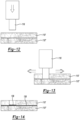
- the ultrasonic tool 116 such as a welding horn or a sonitrode, is disposed above two three-dimensional mesh structures 110' and 110."
- the ultrasonic tool 116 is shown to have penetrated the top (as illustrated) three-dimensional mesh structure 110.'
- the reference to the "top" mesh structure 110' refers to the orientation illustrated in Figure 12 and does not limit this disclosure to any particular orientation.
- the ultrasonic tool 116 is then moved back and forth as shown by the arrows in Figure 13 relative to the lower three-dimensional mesh structure 110" creating ultrasonic vibrations and friction between the two mesh structures 110' and 110" to form the plate 138 as shown in Figure 14 of melted polymer between the two three-dimensional mesh structures 110' and 110.”
- a method comprising the steps of providing a body 110 comprising a plurality of extruded polymer filaments 112 randomly connected to form a three-dimensional structure in a first shape, heating portions of the extruded polymer filaments 112 with an ultrasonic tool 116, and welding at least some of the portions of the extruded polymer filaments 112 together with the ultrasonic tool 116 to form the portions of the extruded polymer filaments 112 into a second shape.
- Another aspect of this method comprises the added steps of assembling a film 114 to the body 110 in the second shape, and heating at least a portion of the extruded polymer filaments 112 and the film 114 to weld the film 114 to the extruded polymer filaments 112 and form a skin on the body 110.
- the plurality of extruded polymer filaments 112 define a plurality of spaces on the body 110 that are spanned by the film 114.
- Another aspect of this method comprises the added steps of providing a second body 110" comprising a second plurality of extruded polymer filaments 112 randomly connected to form a second three-dimensional structure comprising a second exterior surface formed by the extruded polymer filaments 112, assembling the first exterior surface of the first body 110' into contact with the second exterior surface of the second body, heating a first area of the first exterior surface of the first body 110' and a second area of the second exterior surface of the second body 110", and welding the first area of the first exterior surface of the first body 110' to the second area of the second exterior surface of the second body 110" to join the first body 110' to the second body 110".
- portions of the body of extruded polymer filaments 112 are cut-off with an ultrasonic cutting tool 116 to form the body 110.
- Another aspect of this method comprises the added step of inserting the ultrasonic tool 116 into at least a portion of the body 110 to form a trench 120 comprising a first wall 122A and a second wall 122B formed by welding a first portion of the extruded polymer filaments 112 together to form the first wall 122A and by welding and a second portion of the extruded polymer filaments together to form the second wall 122B.
- Another aspect of this method comprises the added steps of contacting a local area of the body 110 with the ultrasonic tool 116, wherein the ultrasonic tool 116 is an ultrasonic welding tool, and welding the extruded polymer filaments 112 in the local area contacted by the ultrasonic welding tool 116 that bonds the extruded polymer filaments 112 in the local area together to form the three-dimensional structure in the first shape into a second shape that is different than the first shape.
- Another aspect of this method comprises the added steps of penetrating the body 110 in a local area of an outer surface of the body 110 with the ultrasonic tool 116, wherein the ultrasonic tool 116 is an ultrasonic welding tool, and compressing the extruded polymer filaments 112 together at a location inside the body 110 with the ultrasonic welding tool 116, and welding the extruded polymer filaments 112 that are compressed by the ultrasonic welding tool 116 to bond the extruded polymer filaments 112 together in the location inside the body 110.
- the extruded polymer filaments 112 are formed of linear low-density polyethylene or high-density polyethylene.
- Another aspect of this method comprises the added steps of assembling a film 114 to the body 110, and heating at least a portion of the extruded polymer filaments 112 and the film 114, welding the film 114 to the extruded polymer filaments 112 to form a skin on the body 110, wherein the film 114 is formed of linear low-density polyethylene or high-density polyethylene.
- Another aspect of this method comprises the added step of inserting the ultrasonic tool 116 into at least a portion of the body 110 to form a trench 120 comprising a first wall 122A and a second wall 122B formed by welding a first portion of the extruded polymer filaments together to form the first wall 122A and by welding and a second portion of the extruded polymer filaments together to form the second wall 122B, wherein the step of inserting the ultrasonic tool 116 into the body 110 is performed by partially or fully inserting the ultrasonic tool 116 through the body 110.
- the ultrasonic tool 116 is manipulated with a robot 119.
- an apparatus comprising a body 110 comprising a plurality of extruded polymer filaments 112 randomly connected to form a first three-dimensional structure comprising a first shape formed by the extruded polymer filaments 112, and forming the body 110 by heating an area of the body 110 with an ultrasonic tool 116 that modifies a portion of the extruded polymer filaments 112 to form a second three-dimensional structure comprising a second shape that is different than the first shape.
- a skin of extruded polymer film 114 is welded to the extruded polymer filaments 112 on the second three-dimensional structure comprising a second shape.
- the body 110 is a first body 110' comprising a second shape and further comprises a second body 110" comprising a plurality of extruded polymer filaments 112 randomly connected to form a second three-dimensional structure formed by the extruded polymer filaments 112, and at least one weld formed between the first body and the second body.
- the body defines at least one internal trench 120 comprising at least a first wall 122A and a second wall 122B facing each other, wherein the first wall 122A and the second wall 122B are formed by welding a first portion of the extruded polymer filaments in the first wall 122A together and by welding a second portion of the extruded polymer filaments in the second wall 122B together.
- the body 110 defines an opening 120 extending from a first exterior periphery of the body 110 to a location within the body 110, and wherein at the location within the body 110 at least some of the extruded polymer filaments 112 are welded together to form an attachment anchor 136.
- the attachment anchor 136 formed at the location inside the body 110 is selected from a group comprising a fastener receptacle, a clip, a planar member 138, or a loop.
- a skin of extruded polymer film 114 welded to the extruded polymer filaments 112 of the three-dimensional structure comprising the second shape, wherein the skin of the extruded polymer film 114 is formed of linear low-density polyethylene or high-density polyethylene.
Landscapes
- Engineering & Computer Science (AREA)
- Mechanical Engineering (AREA)
- Textile Engineering (AREA)
- Composite Materials (AREA)
- Chemical & Material Sciences (AREA)
- Manufacturing & Machinery (AREA)
- Physics & Mathematics (AREA)
- Thermal Sciences (AREA)
- Transportation (AREA)
- Aviation & Aerospace Engineering (AREA)
- Robotics (AREA)
- Lining Or Joining Of Plastics Or The Like (AREA)
- Extrusion Moulding Of Plastics Or The Like (AREA)
Abstract
Description
- This application claims the benefit of
U.S. provisional application Serial No. 63/452,914 filed March 17, 2023 - This relates to a three-dimensional mesh structure and a method of assembly.
-
-
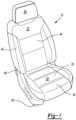
FIGURE 1 is a perspective view of an example of a seat assembly comprising, in part, a three-dimensional filament mesh structure; -
FIGURE 2 is schematic view of an example of a manufacturing system for making the filament mesh structure; -
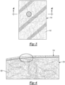
FIGURE 3 is a diagrammatic view of a three-dimensional mesh structure formed of randomly looped and bonded filaments with a film applied to the exterior surface of the three-dimensional mesh structure. -
FIGURE 4 is a cross section view of the three-dimensional mesh structure from the circled portion inFigure 3 with a polymer film skin bonded to the randomly looped and bonded filaments. -
FIGURE 5 is a diagrammatic elevation view of an ultrasonic tool and two three-dimensional mesh structures assembled together with the ultrasonic tool heating an adjoining surface of each three-dimensional mesh structure to weld them together. -
FIGURE 6 is a diagrammatic perspective view of a three-dimensional mesh structure with an ultrasonic tool forming a trench in the three-dimensional mesh structure. -
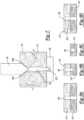
FIGURE 7 is a diagrammatic cross section view of an ultrasonic tool forming a trench in a three-dimensional mesh structure. -
FIGURE 8A - 8D are diagrammatic cross section views of four alternative embodiments of the tool forming four different types of trenches in the three-dimensional mesh structure. -
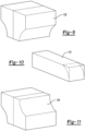
FIGURE 9 is a diagrammatic perspective view of an ultrasonic forming tool for molding the perimeter and for shallow depth enhancement of surface features. -
FIGURE 10 is a diagrammatic perspective view of a three-dimensional mesh structure showing the initial shape thereof in solid lines with the shape shown in dashed lines formed by the ultrasonic forming tool shown inFigure 9 . -
FIGURE 11 is a diagrammatic perspective view of an alternative embodiment of an ultrasonic forming tool for molding the perimeter and for shallow depth enhancement of surface features. -
FIGURE 12 is a diagrammatic perspective view of an ultrasonic forming tool disposed above two three-dimensional mesh structures. -
FIGURE 13 is a diagrammatic perspective view of an ultrasonic forming tool penetrating one of the two three-dimensional mesh structures to form an opening therein. -
FIGURE 14 is a diagrammatic perspective view of an ultrasonic forming tool removed after penetrating one of the two three-dimensional mesh structures to form an opening therein. - Reference will now be made in detail to embodiments, examples of which are illustrated in the accompanying drawings. In the following detailed description, numerous specific details are set forth to provide a thorough understanding of the various described embodiments. However, it will be apparent to one of ordinary skill in the art that the various described embodiments is practiced without these specific details. In other instances, well-known methods, procedures, components, circuits, and networks have not been described in detail so as not to unnecessarily obscure aspects of the embodiments.
- It is to be understood that the disclosed embodiments are merely exemplary and that various and alternative forms are possible. The figures are not necessarily to scale. Some features may be exaggerated or minimized to show details of particular components. Therefore, specific structural and functional details disclosed herein are not to be interpreted as limiting, but merely as a representative basis for teaching one skilled in the art to variously employ embodiments according to the disclosure.
- "One or more" includes a function being performed by one element, a function being performed by more than one element, e.g., in a distributed fashion, several functions being performed by one element, several functions being performed by several elements, or any combination of the above.
- It will also be understood that, although the terms first, second, etc. are, in some instances, used herein to describe various elements, these elements should not be limited by these terms. These terms are only used to distinguish one element from another For example, a first contact could be termed a second contact, and, similarly, a second contact could be termed a first contact, without departing from the scope of the various described embodiments. The first contact and the second contact are both contacts, but they are not the same contact.
- The terminology used in the description of the various described embodiments herein is for the purpose of describing particular embodiments only and is not intended to be limiting. As used in the description of the various described embodiments and the appended claims, the singular forms "a", "an" and "the" are intended to include the plural forms as well, unless the context clearly indicates otherwise. It will also be understood that the term "and/or" as used herein refers to and encompasses any and all possible combinations of one or more of the associated listed items. It will be further understood that the terms "includes," "including," "comprises," and/or "comprising," when used in this specification, specify the presence of stated features, integers, steps, operations, elements, and/or components, but do not preclude the presence or addition of one or more other features, integers, steps, operations, elements, components, and/or groups thereof.
- As used herein, the term "if' is, optionally, construed to mean "when" or "upon" or "in response to determining" or "in response to detecting," depending on the context. Similarly, the phrase "if it is determined" or "if [a stated condition or event] is detected" is, optionally, construed to mean "upon determining" or "in response to determining" or "upon detecting [the stated condition or event]" or "in response to detecting [the stated condition or event]," depending on the context.
- Referring to
Figures 1 and3 , an example of a three-dimensional mesh structure 110 for aseat assembly 10 is shown. In some embodiments, theseat assembly 10 is a vehicle seat assembly, such as for a land vehicle like a car, truck, bus, or the like, or for a non-land vehicle like aircraft or watercraft. For example, aseat assembly 10 for a land vehicle may be shaped and sized as a front row driver or passenger seat, a second, third, or other rear row seat, and may include bucket-style seats as shown, bench-style seats, or other seat styles. Furthermore, theseat assembly 10 may be a non-stowable seat or a stowable seat that may be foldable and stowable in a cavity in the vehicle floor. Additionally, theseat assembly 10 may be configured for non-vehicle applications such as furniture. - In the configuration shown in
Figure 1 , theseat assembly 10 includes aseat bottom 20 and aseat back 22. It is contemplated that theseat back 22 may be omitted in some configurations, such as when theseat assembly 10 is configured as a motorcycle seat or stool. - The
seat bottom 20 is configured to receive a seated occupant and support the pelvis and thighs of the seat occupant. Theseat bottom 20 includes aseat bottom frame 30, acushion 32, and atrim cover 34. - The
seat bottom frame 30 is a structure that supports thecushion 32. Theseat bottom frame 30 includes one or more structural members and may be made of any suitable material, such as a metal alloy, polymeric material, fiber reinforced polymeric material, or combinations thereof. In some configurations, theseat bottom frame 30 includes a panel, seat pan, suspension mat, or suspension wires upon which thecushion 32 is disposed. - The
cushion 32 is disposed on theseat bottom frame 30. Thecushion 32 is made of a compliant material that supports the seat occupant and distributes load forces from the seat occupant to theseat bottom frame 30. Thecushion 32 and associated methods of manufacture will be discussed in more detail below. - The
trim cover 34 covers at least a portion of thecushion 32. In addition, thetrim cover 34 provides one or more visible exterior surfaces of theseat back 22. The seat occupant may be disposed on thetrim cover 34 when seated upon theseat assembly 10. Thetrim cover 34 is made of any suitable material or materials, such as fabric, leather, leatherette, vinyl, or combinations thereof. Thetrim cover 34 may include a plurality of trim panels that are assembled in any suitable manner, such as by fusing or stitching. Thetrim cover 34 is attached to theseat bottom frame 30, thecushion 32, or both. For example, thetrim cover 34 may include trim attachment features that are attached to theseat bottom frame 30, thecushion 32, or both, to inhibit removal of thetrim cover 34 and help conform thetrim cover 34 to the contour of theseat bottom frame 30, thecushion 32, or both. Thetrim cover 34 may also be attached to an attachment pad as will be discussed in more detail below. - The
seat back 22 is configured to support the back of a seated occupant. Theseat back 22 is disposed adjacent to theseat bottom 20. For example, theseat back 22 may be disposed above theseat bottom 20 and near the rear side of theseat bottom 20. Theseat back 22 extends in a generally upward direction away from theseat bottom 20. In some configurations, the seat back 22 is mounted to the seat bottom 20 and may be pivotable with respect to theseat bottom 20. In other configurations, the seat back 22 is not mounted to theseat bottom 20. For instance, a vehicle seat back may be mounted to the vehicle body structure, such as in some second-row seat assemblies. The seat back 22 includes a seat backframe 40, acushion 42, atrim cover 44, and optionally ahead restraint 46. - The seat back
frame 40 is a structure that supports thecushion 42. The seat backframe 40 includes one or more structural members and may be made of any suitable material, such as a metal alloy, polymeric material, fiber reinforced polymeric material, or combinations thereof. In some configurations, the seat backframe 40 includes a panel, pan, suspension mat, or suspension wires upon which thecushion 42 is disposed. It is also contemplated that the seat backframe 40 may be integrally formed with theseat bottom frame 30 in some configurations. - The
cushion 42 is disposed on the seat backframe 40. Thecushion 42 is made of a compliant material that supports the seat occupant and distributes load forces from the seat occupant to the seat backframe 40. It is contemplated that thecushion 42 may be integrally formed with thecushion 32 of the seat bottom 20 or may be separate from thecushion 32 of theseat bottom 20. Thecushion 42 and associated methods of manufacture will be discussed in more detail below. - The
trim cover 44 covers at least a portion of thecushion 42. In addition, thetrim cover 44 provides one or more visible exterior surfaces of the seat back 22. The seat occupant may be disposed on thetrim cover 44 when seated upon theseat assembly 10. Thetrim cover 44 is made of any suitable material or materials, such as fabric, leather, leatherette, vinyl, or combinations thereof. Thetrim cover 44 may include one trim panel or a plurality of trim panels that are assembled in any suitable manner, such as by fusing or stitching. Thetrim cover 44 is attached to the seat backframe 40, thecushion 42, or both. For example, thetrim cover 44 may include trim attachment features that are attached to the seat backframe 40, thecushion 42, or both, to inhibit removal of thetrim cover 44 and help conform thetrim cover 44 to the contour of the seat backframe 40, thecushion 42, or both. Thetrim cover 44 may also be attached to an attachment pad as will be discussed in more detail below. - The
head restraint 46, if provided, is configured to support the head of a seat occupant. Thehead restraint 46 is disposed at the top of the seat back 22 or at an end of the seat back 22 that is disposed opposite theseat bottom 20. Thehead restraint 46 may be moveable in one or more directions with respect to the seat back 22 or may be integrally formed with the seat back 22. - An example of a
manufacturing system 60 of making a cushion or filament mesh structure is shown inFigure 2 . In this example, themanufacturing system 60 includes amaterial supply 70, anextruder 72, and afunnel 74. Themanufacturing system 60 also includes acooling tank 76, and amaterial handling subsystem 78. - Referring to
Figures 2 and3 , thematerial supply 70 holds material stock that is to be extruded, such as solid beads, flakes, granules, pellets, or powder made of the material. In some configurations, thematerial supply 70 is configured as a container or hopper. Thematerial supply 70 provides material stock to theextruder 72. - The
extruder 72 melts the material stock and extrudes the material stock into a plurality offilaments 112. Theextruder 72 may have any suitable configuration. In some configurations, theextruder 72 includes a barrel that receives a rotatable screw and heating elements. Rotation of the screw forces the material to move through the barrel and helps heat the material due to the friction generated as the screw rotates. The material exits the barrel under pressure and in a molten state and is transported under pressure to a die 80 of theextruder 72. - The
die 80, which may also be referred to as a die plate or extrusion die, has multiple through holes or filament forming openings through which the molten material passes. Asingle filament 112 is extruded from each through hole. Thefilaments 112 fall downward from thedie 80 under the force of gravity into thefunnel 74. - The
funnel 74 consolidates or groups thefilaments 112 into a more compact arrangement in which the filaments bend, curl, or loop and afilament 112 contacts and bonds to at least oneother filament 112. Thefunnel 74 has an inlet opening or funnel inlet and an outlet opening or funnel outlet that is smaller than the funnel inlet. Individual separatedfilaments 112 enter the funnel inlet. Thefilaments 112 bend, curl, or loop and move into contact as they accumulate. Thefilaments 112 move through thefunnel 74 toward the funnel outlet. Some filaments may slide along thefunnel 74 or an intervening sheet that is disposed on thefunnel 74 as the filaments move toward the funnel outlet. Bonds are formed betweenfilaments 112 at the points of contact while openings or voids betweenfilaments 112 are present at other locations where onefilament 112 does not contact or bond to anotherfilament 112. The entangled and bondedfilaments 112 pass through the funnel outlet of thefunnel 74 and enter thecooling tank 76. For convenience in reference, the bondedfilaments 112 are referred to as a mesh member orfilament mesh structure 110. - The
cooling tank 76 holds a liquid, such as water or a mixture of water and another fluid. The liquid in thecooling tank 76 helps support the entangled and bondedfilaments 112 to limit further compacting or consolidation of thefilaments 112 into a less open or less porous arrangement and maintains a desired porosity and density of thefilament mesh structure 110. Thus, the liquid provides some buoyancy or resistance that can result in additional bending, curling, or looping of thefilaments 112 adjacent to the surface of the liquid or within thefunnel 74 to further build thefilament mesh structure 110. The liquid also cools thefilaments 112 when thefilaments 112 are in the liquid. For instance, the liquid cools thefilaments 112 from the outside to solidify thefilaments 112 and prevent thefilaments 112 from bonding at additional locations. At this point, thefilaments 112 are relatively stiff and no longer in a plastic state and thus generally maintain a shape and are not moldable or reformable without being reheated. - The
material handling subsystem 78 transports thefilament mesh structure 110 through thecooling tank 76. Thematerial handling subsystem 78 includes various rollers and conveyors that help move thefilament mesh structure 110 through the liquid and out of the liquid. In some configurations, atractor conveyor 92 is provided in thecooling tank 76 to help pull thefilament mesh structure 110 away from thefunnel 74 and to counter buoyancy of thefilaments 112. - One or more other rollers, such as
roller 94, keep thefilament mesh structure 110 submerged in the liquid and guide thefilament mesh structure 110 through thecooling tank 76. For example, theroller 94 may guide thefilament mesh structure 110 toward aconveyor belt 96 and shaker table 98 that are disposed outside of thecooling tank 76. The shaker table 98 shakes thefilament mesh structure 110 while it is on theconveyor belt 96 to remove liquid. Alternatively, or in addition, thefilament mesh structure 110 may be squeezed to remove liquid, air may be blown toward thefilament mesh structure 110 to help remove liquid from thefilament mesh structure 110, or both. It is also contemplated that thefilament mesh structure 110 may also be allowed to drip dry, or dry in ambient air. - The
manufacturing system 60 described above is a continuous flow process in which thefilament mesh structure 110 is formed as a continuous structure when filament extrusion is not interrupted. Further processing of thefilament mesh structure 110 is provided after exiting thecooling tank 76 to cut thefilament mesh structure 110 into individual pieces or blanks for individual cushions. Such processing is conducted by a cutting subsystem of themanufacturing system 60. The cutting system may be of any suitable type. For instance, the cutting system may employ a blade, knife, hot knife, saw, fluid jet, or the like to cut thefilaments 112 of thefilament mesh structure 110 into a blank. The cutting system may be used to shape or contour the blank. It is also contemplated that a blank may be further shaped or contoured with other manufacturing processes, such as molding of the entire blank or a portion thereof. - Referring to
Figures 1 and3 , an example of a three-dimensional mesh structure 110 is shown. The three-dimensional mesh structure 110 may be a cushion, such as a cushion for a vehicle seat. A three-dimensional mesh structure 110 for a vehicle seat may be provided with a seat back 22, a seat bottom 20, or combinations thereof. The three-dimensional mesh structure 110 may be at least partially concealed by thetrim cover 34 and may be directly or indirectly supported by a support structure of a seat assembly, such as aseat bottom frame 30, aseatback frame 40, a panel, support wires, or the like. Alternatively, the three-dimensional mesh structure 110 can be used as padding for other interior trim parts. - The three-
dimensional mesh structure 110 is a three-dimensional mesh structure 110 formed of randomly looped and bondedfilaments 112. In the drawing figures,filaments 112 of the three-dimensional mesh structure 110 are pictorially represented by randomly drawn lines to represent a section view of the three-dimensional mesh structure 110. Thefilaments 112 may be extruded filaments that are made of a thermoplastic material, such as a thermoplastic resin that is polyamide-based, polyester-based, polyimide-based, polyolefin-based, polypropylene-based, polystyrene-based, or combinations thereof. Thefilaments 112 may be made of linear low-density polyethylene (LLDPE) or high-density polyethylene (HDPE). As such, the three-dimensional mesh structure 110 and itsfilaments 112 are not made of foam, such as urethane or polyurethane foam, and the three-dimensional mesh structure 110 may partially or completely replace a conventional foam seat cushion. It is also contemplated that if afilament 112 includes reinforcement fibers, the reinforcement fibers need not be made of a thermoplastic polymer but may be organic material, inorganic material, or a thermoset polymer. - The
extruded filaments 112 may be randomly looped, curled, or entangled and may be bonded together where onefilament 112 contacts another, thereby resulting in a lightweight, air permeable cushion defining openings or voids between thefilaments 112. A method of making an extruded filament mesh cushion is disclosed inUnited States patent application number 17/555,875 , which is hereby incorporated by reference in its entirety. - Referring to
Figures 1 and3 , an example of a three-dimensional mesh structure 110 comprising thecushion 32 is shown. Thecushion 32 is generically designated withreference number 32 for convenience in reference. It is to be understood that the structure and description of thecushion 32 is applicable to thecushion 32 of the seat bottom 20, thecushion 42 of the seat back 22, or both. - The
cushion 32 is a non-foam component or includes at least one non-foam component. The non-foam component is primarily referred to as a mesh member but may also be referred to as a stranded member, looped member, entangled member, filament mesh structure, mesh structure, stranded mesh, looped mesh, entangled mesh, or mesh cushion. Thecushion 32 is depicted as a non-foam component that does not include a foam component or foam material, such as urethane or polyurethane foam; however, it is contemplated that thecushion 32 may also include a foam component or foam material in addition to a non-foam component to provide additional cushioning or localized cushioning for a seat occupant. For example, foam material may be provided between thecushion 32 and a trim cover (e.g.,trim cover 34, 44) that is disposed on thecushion 32, within thecushion 32, or combinations thereof. Reducing the amount of foam material that is provided with thecushion 32 or eliminating foam material from thecushion 32 reduces weight and may improve support and comfort of a seat occupant. In addition, eliminating foam material may facilitate recycling of thecushion 32. - The
cushion 32 is described below in the context of acushion 32 that does not include foam material. In this context, the three-dimensional mesh structure 110 is made offilaments 112 of polymeric material that are randomly looped, bent, curled, or entangled and are bonded together as will be discussed in more detail below. An example offilaments 112 is shown inFigures 3-4 . Afilament 112 is directed bonded to anotherfilament 112 rather than being indirectly bonded with a resin or other intermediate material. - The
filaments 112, which may also be referred to as strands or threads, are made of any suitable material or materials. In some configurations, thefilaments 112 are made of a polymeric material or thermoplastic material, such as a thermoplastic resin that is polyamide-based, polyester-based, polyimide-based, polyolefin-based (e.g., polypropylene-based, polyethylene-based, etc.), polystyrene-based, or combinations thereof. As one example, a polyethylene-based filament may be made of linear low-density polyethylene (LLPDE). The filament material may be recyclable unlike foam material or more easily recycled than foam material. It is also contemplated that afilament 112 may comprise reinforcement fibers and that the reinforcement fibers may not be made of a thermoplastic material. - In some configurations, a
filament 112 may be a monofilament that is made of a single material. In some configurations, afilament 112 is made of multiple materials. As an example, afilament 112 made of multiple materials may include a core that is made of a first thermoplastic material and a sheath that encircles the core and is made of a second thermoplastic material that differs from the first thermoplastic material. It is contemplated that thecushion 32 may include a combination of monofilaments and filaments that are made of multiple materials and are not monofilaments. -
Filaments 112 that are randomly looped, bent, looped, curled, or entangled are bonded together where onefilament 112 contacts anotherfilament 112, thereby resulting in a lightweight, air permeable cushion (e.g.,cushion 32 and/or 42) or mesh structure defining openings or voids between thefilaments 112. - The process used to make a three-
dimensional mesh structure 10 may result in a three-dimensional mesh structure 110 that has a generally uniform cross-section, such as a rectangular cross-section. Moreover, thefilaments 112 of the three-dimensional mesh structure 110 may be cooled and hardened such that thefilaments 112 are relatively stiff and no longer in a plastic state and thus not moldable or formable. A generally uniform cross-section may not provide a desired seat profile or other part profile. The cross section of the three-dimensional mesh structure 110 is altered from its original generally uniform cross-sectional profile to provide one or more indentations, protruding regions, curved regions, and the like. - Referring to
Figures 3 and 4 , the three-dimensional mesh structure 110 is shown with a layer offilm 114 attached to the outer surface of the three-dimensional mesh structure 110. Thefilm 114 and thefilaments 112 in one embodiment are both formed of a thermoplastic material such as linear low-density polyethylene (LLDPE) or high-density polyethylene (HDPE). Thefilm 114 is wrapped about the exterior surface of the three-dimensional mesh structure 110 and heat is applied to thefilm 114 and three-dimensional mesh structure 110 to melt thefilm 114 and weld thefilm 114 to thefilaments 112. - Referring to
Figure 5 , anultrasonic tool 116 operated as an end effector of arobot 119. Theultrasonic tool 116 is shown to be inserted between two three-dimensional mesh structures 110' and 110." Theultrasonic tool 116 ultrasonically heats the two three-dimensional mesh structures 110' and 110" at a location where they are to be welded together. As an alternative, thetool 116 is one that comprises a resistance heating system, or a laser heating system can be used to heat the two three-dimensional mesh structures 110' and 110" and weld them together. - Referring to
Figures 6 and7 , an internal trenching system is disclosed wherein anultrasonic trenching tool 118 is shown to be forming atrench 120 in the three-dimensional mesh structure 110. Theultrasonic trenching tool 118 forms atrench 120 comprising twowalls polymer filaments 112 together to form thefirst wall 122A on one side of thetrenching tool 118 and by welding a second portion of the extrudedpolymer filaments 112 together to form thesecond wall 122B on another side of thetrenching tool 118. Referring toFigure 7 , thetrenching tool 118 is shown to penetrate fully through a three-dimensional mesh structure 110 that is backed by asupport member 124 that defines a relief opening 226. - Referring to
Figures 8A - 8D , examples of four different applications for the use of thetrenching tool 118 described above are illustrated. InFigure 8A , aslot 120 defined by themesh structures 110' and 110" extends completely through two three-dimensional mesh structures 110' and 110." InFigure 8B , aslot 120 defined by themesh structures 110' and 110" extends completely through a first three-dimensional mesh structure 110' and a partially through a second three-dimensional mesh structure 110". InFigure 8C , aslot 120 defined by themesh structures 110' and 110" extends partially through a single three-dimensional mesh structure 110. InFigure 8D , aslot 120 defined by themesh structures 110' and 110" extends completely through two three-dimensional mesh structures 110 as inFigure 8A . The trenching tool 118 (shown inFigure 7 ) also forms arelief area 128 at the same time as thetrenching tool 118 plunge cuts thetrench 120. Therelief area 128 is formed by an upper portion of thetrenching tool 118 - Referring to
Figures 9 and 10 , anultrasonic molding tool 132 is illustrated that has a symmetrical shape that tunes and balances the ultrasonic output of themolding tool 132. Thetool 132 is moved into engagement with the three-dimensional mesh structure 110 shown inFigure 10 . The three-dimensional mesh structure 110 is initially provided as a rectangular block as shown in solid lines inFigure 10 . The three-dimensional mesh structure 110 is formed to have a rounded perimeter as shown in dashed lines inFigure 10 after being molded by themolding tool 132. Heating the filaments 112 (shown inFigures 3 and 4 ) with the ultrasonic energy melts thefilaments 112 to approach the melting point of thefilaments 112 while pressure is applied by themolding tool 132. When themolding tool 132 is retracted, thefilaments 112 are cooled to hold the shape pressed by themolding tool 132. Themolding tool 132 can also be used to form surface features of a shallow depth. - Referring to
Figure 11 , an alternative embodiment of amolding tool 134 is illustrated that is provided as two halves that are inversely symmetrical to tune and balance the ultrasonic output of themolding tool 134. Thetool 134 is used in a manner similar to the tool ofFigure 9 . - Referring to
Figures 12-14 , a process for forming aplate 138 orreceptacle 136 in the three-dimensional mesh structures 110' and 110" is disclosed. Thereceptacle 136 comprises a clip, a bar, or a portion of theplate 138 that various fasteners are secured to for attaching a seat cover, trim part, or other accessories to the three-dimensional mesh structure 110. InFigure 12 , theultrasonic tool 116, such as a welding horn or a sonitrode, is disposed above two three-dimensional mesh structures 110' and 110." InFigure 13 , theultrasonic tool 116 is shown to have penetrated the top (as illustrated) three-dimensional mesh structure 110.' The reference to the "top" mesh structure 110' refers to the orientation illustrated inFigure 12 and does not limit this disclosure to any particular orientation. Theultrasonic tool 116 is then moved back and forth as shown by the arrows inFigure 13 relative to the lower three-dimensional mesh structure 110" creating ultrasonic vibrations and friction between the twomesh structures 110' and 110" to form theplate 138 as shown inFigure 14 of melted polymer between the two three-dimensional mesh structures 110' and 110." - According to one aspect of this disclosure, a method is disclosed comprising the steps of providing a
body 110 comprising a plurality of extrudedpolymer filaments 112 randomly connected to form a three-dimensional structure in a first shape, heating portions of the extrudedpolymer filaments 112 with anultrasonic tool 116, and welding at least some of the portions of the extrudedpolymer filaments 112 together with theultrasonic tool 116 to form the portions of the extrudedpolymer filaments 112 into a second shape. - Another aspect of this method comprises the added steps of assembling a
film 114 to thebody 110 in the second shape, and heating at least a portion of the extrudedpolymer filaments 112 and thefilm 114 to weld thefilm 114 to the extrudedpolymer filaments 112 and form a skin on thebody 110. - According to another aspect of the method, the plurality of extruded
polymer filaments 112 define a plurality of spaces on thebody 110 that are spanned by thefilm 114. - Another aspect of this method comprises the added steps of providing a
second body 110" comprising a second plurality of extrudedpolymer filaments 112 randomly connected to form a second three-dimensional structure comprising a second exterior surface formed by the extrudedpolymer filaments 112, assembling the first exterior surface of the first body 110' into contact with the second exterior surface of the second body, heating a first area of the first exterior surface of the first body 110' and a second area of the second exterior surface of thesecond body 110", and welding the first area of the first exterior surface of the first body 110' to the second area of the second exterior surface of thesecond body 110" to join the first body 110' to thesecond body 110". - According to one aspect of this disclosure, portions of the body of extruded
polymer filaments 112 are cut-off with anultrasonic cutting tool 116 to form thebody 110. - Another aspect of this method comprises the added step of inserting the
ultrasonic tool 116 into at least a portion of thebody 110 to form atrench 120 comprising afirst wall 122A and asecond wall 122B formed by welding a first portion of the extrudedpolymer filaments 112 together to form thefirst wall 122A and by welding and a second portion of the extruded polymer filaments together to form thesecond wall 122B. - Another aspect of this method comprises the added steps of contacting a local area of the
body 110 with theultrasonic tool 116, wherein theultrasonic tool 116 is an ultrasonic welding tool, and welding the extrudedpolymer filaments 112 in the local area contacted by theultrasonic welding tool 116 that bonds the extrudedpolymer filaments 112 in the local area together to form the three-dimensional structure in the first shape into a second shape that is different than the first shape. - Another aspect of this method comprises the added steps of penetrating the
body 110 in a local area of an outer surface of thebody 110 with theultrasonic tool 116, wherein theultrasonic tool 116 is an ultrasonic welding tool, and compressing the extrudedpolymer filaments 112 together at a location inside thebody 110 with theultrasonic welding tool 116, and welding the extrudedpolymer filaments 112 that are compressed by theultrasonic welding tool 116 to bond the extrudedpolymer filaments 112 together in the location inside thebody 110. - According to another aspect of the method, the extruded
polymer filaments 112 are formed of linear low-density polyethylene or high-density polyethylene. - Another aspect of this method comprises the added steps of assembling a
film 114 to thebody 110, and heating at least a portion of the extrudedpolymer filaments 112 and thefilm 114, welding thefilm 114 to the extrudedpolymer filaments 112 to form a skin on thebody 110, wherein thefilm 114 is formed of linear low-density polyethylene or high-density polyethylene. - Another aspect of this method comprises the added step of inserting the
ultrasonic tool 116 into at least a portion of thebody 110 to form atrench 120 comprising afirst wall 122A and asecond wall 122B formed by welding a first portion of the extruded polymer filaments together to form thefirst wall 122A and by welding and a second portion of the extruded polymer filaments together to form thesecond wall 122B, wherein the step of inserting theultrasonic tool 116 into thebody 110 is performed by partially or fully inserting theultrasonic tool 116 through thebody 110. - According to another aspect of the method, the
ultrasonic tool 116 is manipulated with arobot 119. - According to one aspect of this disclosure, an apparatus is disclosed comprising a
body 110 comprising a plurality of extrudedpolymer filaments 112 randomly connected to form a first three-dimensional structure comprising a first shape formed by the extrudedpolymer filaments 112, and forming thebody 110 by heating an area of thebody 110 with anultrasonic tool 116 that modifies a portion of the extrudedpolymer filaments 112 to form a second three-dimensional structure comprising a second shape that is different than the first shape. - According to another aspect of the apparatus, a skin of extruded
polymer film 114 is welded to the extrudedpolymer filaments 112 on the second three-dimensional structure comprising a second shape. - According to another aspect of the apparatus, the
body 110 is a first body 110' comprising a second shape and further comprises asecond body 110" comprising a plurality of extrudedpolymer filaments 112 randomly connected to form a second three-dimensional structure formed by the extrudedpolymer filaments 112, and at least one weld formed between the first body and the second body. - According to another aspect of the apparatus, the body defines at least one
internal trench 120 comprising at least afirst wall 122A and asecond wall 122B facing each other, wherein thefirst wall 122A and thesecond wall 122B are formed by welding a first portion of the extruded polymer filaments in thefirst wall 122A together and by welding a second portion of the extruded polymer filaments in thesecond wall 122B together. - According to another aspect of the apparatus, the
body 110 defines anopening 120 extending from a first exterior periphery of thebody 110 to a location within thebody 110, and wherein at the location within thebody 110 at least some of the extrudedpolymer filaments 112 are welded together to form anattachment anchor 136. - According to another aspect of the apparatus, the
attachment anchor 136 formed at the location inside thebody 110 is selected from a group comprising a fastener receptacle, a clip, aplanar member 138, or a loop. - According to another aspect of the apparatus, a skin of extruded
polymer film 114 welded to the extrudedpolymer filaments 112 of the three-dimensional structure comprising the second shape, wherein the skin of the extrudedpolymer film 114 is formed of linear low-density polyethylene or high-density polyethylene. - While exemplary embodiments are described above, it is not intended that these embodiments describe all possible forms according to the disclosure. In that regard, the words used in the specification are words of description rather than limitation, and it is understood that various changes may be made without departing from the spirit and scope of the disclosure. Additionally, the features of various implementing embodiments may be combined to form further embodiments according to the disclosure.
Claims (15)
- A method, comprising:providing a body comprising a plurality of extruded polymer filaments randomly connected to form a three-dimensional structure in a first shape;heating portions of the extruded polymer filaments with an ultrasonic tool; andwelding at least some of the portions of the extruded polymer filaments together with the ultrasonic tool to form the portions of the extruded polymer filaments into a second shape.
- The method of claim 1, further comprising:assembling a film to the body in the second shape; andheating at least a portion of the extruded polymer filaments and the film to weld the film to the extruded polymer filaments to form a skin on the body.
- The method of claim 1 or 2 wherein the plurality of extruded polymer filaments define a plurality of spaces on the body that are spanned by the film.
- The method of any of the preceding claims, wherein the body is a first body comprising a first exterior surface further comprising:providing a second body comprising a second plurality of extruded polymer filaments randomly connected to form a second three-dimensional structure comprising a second exterior surface formed by the extruded polymer filaments;assembling the first exterior surface of the first body into contact with the second exterior surface of the second body;heating a first area of the first exterior surface of the first body and a second area of the second exterior surface of the second body; andwelding the first area of the first exterior surface of the first body to the second area of the second exterior surface of the second body to join the first body to the second body.
- The method of any of the preceding claims, further comprising:
cutting off portions of the body of extruded polymer filaments to form the body with an ultrasonic cutting tool. - The method of any of the preceding claims, further comprising:
inserting the ultrasonic tool into at least a portion of the body to form a trench comprising a first wall and a second wall formed by welding a first portion of the extruded polymer filaments together to form the first wall and by welding a second portion of the extruded polymer filaments together to form the second wall, wherein preferably the step of inserting the ultrasonic tool into the body is performed by partially or fully inserting the ultrasonic tool through the body, and wherein further preferably the ultrasonic tool is manipulated with a robot. - The method of any of the preceding claims, further comprising:contacting a local area of the body with the ultrasonic tool, wherein the ultrasonic tool is an ultrasonic welding tool; andwelding the extruded polymer filaments in the local area contacted by the ultrasonic welding tool that bonds the extruded polymer filaments in the local area together to form the three-dimensional structure in the first shape into a second shape that is different than the first shape.
- The method of any of the preceding claims further comprising:penetrating the body in a local area of an outer surface of the body with the ultrasonic tool, wherein the ultrasonic tool is an ultrasonic welding tool, and compressing the extruded polymer filaments together at a location inside the body with the ultrasonic welding tool; andwelding the extruded polymer filaments that are compressed by the ultrasonic welding tool to bond the extruded polymer filaments together in the location inside the body to form an attachment anchor at the location inside the body.
- The method of any of the preceding claims wherein the extruded polymer filaments are formed of Linear Low-Density Polyethylene or High-Density Polyethylene.
- The method of claim 1 further comprising:assembling a film to the body; andheating at least a portion of the extruded polymer filaments and the film welding the film to the extruded polymer filaments to form a skin on the body, wherein the film is formed of Linear Low-Density Polyethylene or High-Density Polyethylene.
- An apparatus, comprising:a body comprising a plurality of extruded polymer filaments randomly connected to form a first three-dimensional structure comprising a first shape formed by the extruded polymer filaments; andthe body being formed by heating an area of the body with an ultrasonic tool that modifies a portion of the extruded polymer filaments to form a second three-dimensional structure comprising a second shape that is different than the first shape.
- The apparatus of claim 11, further comprising:
a skin of extruded polymer film welded to the extruded polymer filaments on the second three-dimensional structure comprising a second shape, wherein preferably the skin of the extruded polymer film is formed of linear low-density polyethylene or high-density polyethylene. - The apparatus of claim 11 or 12 wherein the body is a first body comprising a second shape, further comprising:a second body comprising a plurality of extruded polymer filaments randomly connected to form a second three-dimensional structure formed by the extruded polymer filaments; andat least one weld formed between the first body and the second body.
- The apparatus of any of claims 11 to 13, wherein the body defines at least one internal trench comprising at least a first wall and a second wall facing each other, wherein the first wall and the second wall are formed by welding a first portion of the extruded polymer filaments in the first wall together and by welding a second portion of the extruded polymer filaments in the second wall together.
- The apparatus of any of claims 11 to 14, wherein the body defines an opening extending from a first exterior periphery of the body to a location within the body, and wherein at the location within the body at least some of the extruded polymer filaments are welded together to form an attachment anchor, wherein preferably the attachment anchor formed at the location inside the body is selected from a group comprising:a fastener receptacle;a clip;a planar member; anda loop.
Applications Claiming Priority (2)
| Application Number | Priority Date | Filing Date | Title |
|---|---|---|---|
| US202363452914P | 2023-03-17 | 2023-03-17 | |
| US18/587,726 US20240308165A1 (en) | 2023-03-17 | 2024-02-26 | Three-dimensional mesh structures and method of assembly |
Publications (1)
| Publication Number | Publication Date |
|---|---|
| EP4458559A1 true EP4458559A1 (en) | 2024-11-06 |
Family
ID=90366316
Family Applications (1)
| Application Number | Title | Priority Date | Filing Date |
|---|---|---|---|
| EP24163832.9A Pending EP4458559A1 (en) | 2023-03-17 | 2024-03-15 | Three-dimensional mesh structures and method of assembly |
Country Status (5)
| Country | Link |
|---|---|
| US (1) | US20240308165A1 (en) |
| EP (1) | EP4458559A1 (en) |
| JP (2) | JP2024133019A (en) |
| KR (1) | KR20240140855A (en) |
| GB (1) | GB2629896A (en) |
Citations (4)
| Publication number | Priority date | Publication date | Assignee | Title |
|---|---|---|---|---|
| US6010766A (en) * | 1992-08-04 | 2000-01-04 | 3M Innovative Properties Company | Corrugated nonwoven webs of polymeric microfiber |
| US20090191779A1 (en) * | 2008-01-30 | 2009-07-30 | Cree James W | Elastic laminate and method of making |
| US20090311495A1 (en) * | 2005-10-24 | 2009-12-17 | Hunt Technology Limited | Chemical barrier fabric |
| EP3392024A1 (en) * | 2017-04-11 | 2018-10-24 | The Boeing Company | Multifunction end effector apparatus and methods for assembling thermoplastic composite articles |
Family Cites Families (4)
| Publication number | Priority date | Publication date | Assignee | Title |
|---|---|---|---|---|
| JP5030393B2 (en) * | 2004-05-28 | 2012-09-19 | 株式会社シーエンジ | Cushion for bed and manufacturing method thereof |
| KR20130099810A (en) * | 2010-09-01 | 2013-09-06 | 씨엔 컴퍼니 리미티드 | Method for forming cushions |
| EP2532502B1 (en) * | 2011-06-10 | 2019-05-22 | Schukra Gerätebau GmbH | Method of treating a fiber cushion body |
| JP6121953B2 (en) * | 2014-08-07 | 2017-04-26 | 株式会社シーエンジ | Three-dimensional network product, three-dimensional network product manufacturing apparatus, and three-dimensional network product manufacturing method |
-
2024
- 2024-02-26 US US18/587,726 patent/US20240308165A1/en active Pending
- 2024-03-11 GB GB2403493.6A patent/GB2629896A/en active Pending
- 2024-03-14 JP JP2024040402A patent/JP2024133019A/en active Pending
- 2024-03-15 KR KR1020240036165A patent/KR20240140855A/en active Pending
- 2024-03-15 EP EP24163832.9A patent/EP4458559A1/en active Pending
-
2025
- 2025-05-20 JP JP2025083713A patent/JP2025113347A/en active Pending
Patent Citations (4)
| Publication number | Priority date | Publication date | Assignee | Title |
|---|---|---|---|---|
| US6010766A (en) * | 1992-08-04 | 2000-01-04 | 3M Innovative Properties Company | Corrugated nonwoven webs of polymeric microfiber |
| US20090311495A1 (en) * | 2005-10-24 | 2009-12-17 | Hunt Technology Limited | Chemical barrier fabric |
| US20090191779A1 (en) * | 2008-01-30 | 2009-07-30 | Cree James W | Elastic laminate and method of making |
| EP3392024A1 (en) * | 2017-04-11 | 2018-10-24 | The Boeing Company | Multifunction end effector apparatus and methods for assembling thermoplastic composite articles |
Also Published As
| Publication number | Publication date |
|---|---|
| GB202403493D0 (en) | 2024-04-24 |
| JP2024133019A (en) | 2024-10-01 |
| GB2629896A (en) | 2024-11-13 |
| JP2025113347A (en) | 2025-08-01 |
| US20240308165A1 (en) | 2024-09-19 |
| KR20240140855A (en) | 2024-09-24 |
Similar Documents
| Publication | Publication Date | Title |
|---|---|---|
| EP4653252A1 (en) | Seat assembly and method of assembly | |
| US20250338964A1 (en) | Seat cushion and method of assembly | |
| EP4431267A1 (en) | Receptacle assembly for a fastener in filament mesh structure | |
| US20250346165A1 (en) | Cushion and a method of manufacture | |
| US20250368109A1 (en) | Seat assembly and method of manufacture | |
| US20250170935A1 (en) | Seat assembly and method of assembly | |
| EP4477467A1 (en) | Seat assembly, clip, and method of manufacture | |
| US20250388152A1 (en) | Fastener for non-foam cushion | |
| EP4458559A1 (en) | Three-dimensional mesh structures and method of assembly | |
| CN118664913A (en) | Three-dimensional mesh structure and assembly method | |
| US20260000205A1 (en) | Cushion assembly | |
| EP4656455A2 (en) | Seat assembly and method of manufacture | |
| EP4631715A1 (en) | Mesh member assembly and method of manufacture | |
| EP4566787A2 (en) | Cushion, manufacturing tool, and a method of manufacture | |
| BR102024004920A2 (en) | METHOD AND APPARATUS | |
| US20260061907A1 (en) | Cushion assembly and method of assembly | |
| US20250121755A1 (en) | Cushion, manufacturing apparatus, and a method of manufacture | |
| US20250001655A1 (en) | System and method of forming a mesh structure | |
| CN118665294A (en) | Receiver assembly for fasteners in filament networks | |
| DK202470214A1 (en) | Cushion and a method of manufacture | |
| DK202470210A1 (en) | Mesh member assembly and method of manufacture | |
| CN121200892A (en) | Pad assembly |
Legal Events
| Date | Code | Title | Description |
|---|---|---|---|
| PUAI | Public reference made under article 153(3) epc to a published international application that has entered the european phase |
Free format text: ORIGINAL CODE: 0009012 |
|
| STAA | Information on the status of an ep patent application or granted ep patent |
Free format text: STATUS: THE APPLICATION HAS BEEN PUBLISHED |
|
| AK | Designated contracting states |
Kind code of ref document: A1 Designated state(s): AL AT BE BG CH CY CZ DE DK EE ES FI FR GB GR HR HU IE IS IT LI LT LU LV MC ME MK MT NL NO PL PT RO RS SE SI SK SM TR |
|
| P01 | Opt-out of the competence of the unified patent court (upc) registered |
Free format text: CASE NUMBER: APP_5321/2025 Effective date: 20250131 |
|
| STAA | Information on the status of an ep patent application or granted ep patent |
Free format text: STATUS: REQUEST FOR EXAMINATION WAS MADE |
|
| 17P | Request for examination filed |
Effective date: 20250506 |
|
| STAA | Information on the status of an ep patent application or granted ep patent |
Free format text: STATUS: EXAMINATION IS IN PROGRESS |
|
| 17Q | First examination report despatched |
Effective date: 20260312 |